JP5721906B2 - Free-standing marine riser fairing - Google Patents
Free-standing marine riser fairingDownload PDFInfo
- Publication number
- JP5721906B2 JP5721906B2JP2014515902AJP2014515902AJP5721906B2JP 5721906 B2JP5721906 B2JP 5721906B2JP 2014515902 AJP2014515902 AJP 2014515902AJP 2014515902 AJP2014515902 AJP 2014515902AJP 5721906 B2JP5721906 B2JP 5721906B2
- Authority
- JP
- Japan
- Prior art keywords
- fairing
- riser
- folding
- foldable
- deployed
- Prior art date
- Legal status (The legal status is an assumption and is not a legal conclusion. Google has not performed a legal analysis and makes no representation as to the accuracy of the status listed.)
- Active
Links
Images


Classifications
- E—FIXED CONSTRUCTIONS
- E21—EARTH OR ROCK DRILLING; MINING
- E21B—EARTH OR ROCK DRILLING; OBTAINING OIL, GAS, WATER, SOLUBLE OR MELTABLE MATERIALS OR A SLURRY OF MINERALS FROM WELLS
- E21B17/00—Drilling rods or pipes; Flexible drill strings; Kellies; Drill collars; Sucker rods; Cables; Casings; Tubings
- E21B17/01—Risers
- E21B17/012—Risers with buoyancy elements
Landscapes
- Engineering & Computer Science (AREA)
- Geology (AREA)
- Life Sciences & Earth Sciences (AREA)
- Mining & Mineral Resources (AREA)
- Physics & Mathematics (AREA)
- Environmental & Geological Engineering (AREA)
- Fluid Mechanics (AREA)
- Mechanical Engineering (AREA)
- General Life Sciences & Earth Sciences (AREA)
- Geochemistry & Mineralogy (AREA)
- Earth Drilling (AREA)
- Details Of Aerials (AREA)
- Catching Or Destruction (AREA)
- Professional, Industrial, Or Sporting Protective Garments (AREA)
Description
Translated fromJapanese (関連出願への相互参照)
本願は、米国仮特許出願第61/496,631号(2011年6月14日出願)に基づく優先権を主張する。(Cross-reference to related applications)
This application claims priority based on US Provisional Patent Application No. 61 / 496,631 (filed Jun. 14, 2011).
(技術分野)
ライザを水から引き上げて、それをライザ用格納部内に収容するとき、フェアリングを除去する必要性を排除するであろう様式において、スリックジョイントに半恒久的に取り付けられるか、あるいは浮揚性または封入式モジュールのある区画内に埋め込まれる、海洋ライザフェアリングのための保管システム。(Technical field)
When the riser is lifted out of the water and housed in the riser containment, it is semi-permanently attached to the slick joint, or floatable or enclosed, in a manner that would eliminate the need to remove the fairing A storage system for marine riser fairings that is embedded in a compartment with a formula module.
(発明の背景)
本発明は、海洋ライザフェアリングの使用に関する3つの主要な問題に取り組むことを目的としており、第1に、フェアリングを設置/除去するためにかかる時間、掘削船の船内のライザフェアリングのための別個の保管場所を計画する必要性、およびフェアリングを保管場所から設置ステーションに移動させる必要性である。(Background of the Invention)
The present invention aims to address three major issues related to the use of marine riser fairings, firstly, for the time it takes to install / remove the fairings, for the riser fairing in the drilling vessel's ship. There is a need to plan a separate storage location and to move the fairing from the storage location to the installation station.
本問題は、ライザフェアリングを設置するための時間削減の試みによって、過去に取り組まれている。これが達成されたいくつかの方法は、接続部/取付部を浮揚性ジョイントに固着させるために必要とされるステップを単純化し、取扱を容易にするために、フェアリングの長さ/サイズを縮小することによるものである。 This problem has been addressed in the past by attempts to reduce the time to install riser fairings. Several ways in which this has been achieved reduce the length / size of the fairing to simplify the steps required to secure the connection / mounting to the buoyant joint and to facilitate handling It is by doing.
本発明は、ライザのスリックまたは浮揚性あるいは封入式ジョイントにストラップで留められた保管システムから拡張し、かつ、保管システム内に折り畳まれるであろう、自立型折畳式/拡張式海洋ライザフェアリングを対象とする。 The present invention is a self-supporting foldable / expandable marine riser fairing that will expand from and fold into a slick or buoyant or encased joint of the riser and strapped into the storage system Is targeted.
折畳式海洋ライザフェアリングは、必要に応じて、保管空間内に後退し、かつ、保管空間から展開されるように構成される部材を備え、折畳式フェアリングは、ライザに半恒久的に取り付けられる。保管空間は、ボックスをライザに取り付けるための低摩擦取付用ストラップをさらに備える保管ボックスである。折畳式ライザフェアリングは、ライザの浮揚性ジョイントまたは封入式ジョイント内に収容されることができる。 The foldable marine riser fairing comprises a member configured to retract into the storage space and be deployed from the storage space as needed, the foldable fairing is semi-permanent to the riser Attached to. The storage space is a storage box further comprising a low friction attachment strap for attaching the box to the riser. The foldable riser fairing can be housed within the riser's buoyant joint or enclosed joint.
折畳式フェアリングの部材は、保管空間内に折曲され、展開されるとピラミッド形状を形成するように適合される、相互係止パネルを備える。相互係止パネルは、係止スタッドを含む。部材が展開されると平滑薄片を生成するために、付加的材料が、部材の外側に取り付けられる。 The members of the folding fairing comprise interlocking panels that are folded into the storage space and adapted to form a pyramid shape when deployed. The interlocking panel includes a locking stud. Additional material is attached to the outside of the member to produce a smooth flake when the member is deployed.
折畳式フェアリングの部材は、折曲式区画を備え、折曲式区画は、地図折りに折り畳まれるように適合される。折曲式区画は、蛇腹折りに折り畳まれるように適合される。 The foldable fairing member comprises a foldable section, the foldable section being adapted to be folded into a map fold. The folding section is adapted to be folded into a bellows fold.
フェアリングはさらに、展開機構を備える。展開機構は、シザージャッキである。 The fairing further comprises a deployment mechanism. The deployment mechanism is a scissor jack.
折畳式フェアリングの部材は、翼区画を備える。部材は、離間され、かつ、ライザに取り付けられる、2つの翼区画を備える。可鍛性材料が、2つの翼区画およびその間に取り付けられ、可鍛性材料は、折畳式フェアリングが展開されると平滑薄片を形成するように適合される。 The member of the foldable fairing comprises a wing section. The member comprises two wing sections that are spaced apart and attached to the riser. A malleable material is attached to and between the two wing sections, and the malleable material is adapted to form a smooth flake when the foldable fairing is deployed.
前述は、以下の発明を実施するための形態が、より理解され得るために、本発明の特徴および技術的利点をむしろ広義に概略している。本発明の付加的特徴および利点は、本明細書に説明され、本発明の請求項の主題を形成する。開示される概念および具体的実施形態が、本発明の同一の目的を実施するために、修正または他の構造を設計するための基礎として容易に利用され得ることは、当業者によって理解されるはずである。また、そのような同等構造が、添付の請求項に記載されるような本発明の精神および範囲から逸脱しないことは、当業者によって認識されるはずである。その編成および動作方法の両方に関して、本発明の特性であると考えられる新規特徴は、さらなる目的および利点とともに、付随の図と併せて検討されることによって、以下の説明からより理解されるであろう。しかしながら、図はそれぞれ、例証および説明の目的のためだけに提供され、本発明の限定の定義として意図されないものではないことを明示的に理解されたい。
本発明はさらに、たとえば、以下を提供する。
(項目1)折畳式海洋ライザフェアリングであって、必要に応じて、保管空間内に後退し、かつ、前記保管空間から展開されるように構成されている部材を備え、前記折畳式フェアリングは、前記ライザに半恒久的に取り付けられている、折畳式海洋ライザフェアリング。
(項目2)前記保管空間は、保管ボックスである、項目1に記載の装置。
(項目3)前記保管ボックスは、前記ボックスを前記ライザに取り付けるための低摩擦取付用ストラップをさらに備える、項目2に記載の装置。
(項目4)前記折畳式ライザフェアリングは、前記ライザの浮揚性ジョイントまたは封入式ジョイント内に収容される、項目1に記載の装置。
(項目5)前記折畳式フェアリングの部材は、相互係止パネルを備え、前記相互係止パネルは、前記保管空間内に折曲され、展開されるとピラミッド形状を形成するように適合されている、項目1に記載の装置。
(項目6)前記相互係止パネルは、係止スタッドを含む、項目5に記載の装置。
(項目7)前記部材が展開されると平滑薄片を生成するために、付加的材料が、前記部材の外側に取り付けられている、項目5に記載の装置。
(項目8)前記折畳式フェアリングの部材は、折曲式区画を備える、項目1に記載の装置。
(項目9)前記折曲式区画は、地図折りに折り畳まれるように適合されている、項目8に記載の装置。
(項目10)前記折曲式区画は、蛇腹折りに折り畳まれるように適合されている、項目8に記載の装置。
(項目11)前記フェアリングはさらに、展開機構を備える、項目1に記載の装置。
(項目12)前記展開機構は、シザージャッキである、項目11に記載の装置。
(項目13)前記折畳式フェアリングの部材は、翼区画を備える、項目1に記載の装置。
(項目14)前記部材は、離間され、かつ、前記ライザに取り付けられている、2つの翼区画を備える、項目13に記載の装置。
(項目15)可鍛性材料が、前記2つの翼区画およびその間に取り付けられ、前記可鍛性材料は、前記折畳式フェアリングが展開されると平滑薄片を形成するように適合されている、項目14に記載の装置。The foregoing has outlined rather broadly the features and technical advantages of the present invention in order that the detailed description of the invention that follows may be better understood. Additional features and advantages of the invention will be described herein and form the subject of the claims of the invention. It should be understood by those skilled in the art that the disclosed concepts and specific embodiments can be readily utilized as a basis for designing modifications or other structures to carry out the same purposes of the present invention. It is. It should also be recognized by those skilled in the art that such equivalent constructions do not depart from the spirit and scope of the invention as set forth in the appended claims. The novel features believed to be characteristic of the invention, both as to its organization and method of operation, together with further objects and advantages, will be better understood from the following description when considered in conjunction with the accompanying figures. Let's go. It should be expressly understood, however, that each drawing is provided for purposes of illustration and description only and is not intended as a definition of the limitations of the invention.
The present invention further provides, for example:
(Item 1) A foldable marine riser fairing, comprising a member configured to retract into the storage space and to be deployed from the storage space, if necessary, the foldable The fairing is a folding marine riser fairing that is semi-permanently attached to the riser.
(Item 2) The apparatus according to item 1, wherein the storage space is a storage box.
(Item 3) The device according to item 2, wherein the storage box further includes a low-friction attachment strap for attaching the box to the riser.
(Item 4) The apparatus according to item 1, wherein the foldable riser fairing is housed in a buoyant joint or an enclosed joint of the riser.
(Item 5) The folding fairing member comprises an interlocking panel, the interlocking panel being adapted to form a pyramid shape when folded into the storage space and deployed. The apparatus according to item 1.
6. The apparatus of claim 5, wherein the interlocking panel includes a locking stud.
7. The apparatus of claim 5, wherein additional material is attached to the outside of the member to produce a smooth flake when the member is deployed.
(Item 8) The apparatus according to item 1, wherein the member of the folding fairing includes a folding section.
(Item 9) The apparatus according to item 8, wherein the folding section is adapted to be folded into a map fold.
(Item 10) The apparatus according to item 8, wherein the folding section is adapted to be folded into a bellows fold.
(Item 11) The apparatus according to item 1, wherein the fairing further includes a deployment mechanism.
(Item 12) The apparatus according to item 11, wherein the deployment mechanism is a scissor jack.
(Item 13) The apparatus according to item 1, wherein the member of the folding fairing comprises a wing section.
14. The apparatus of claim 13, wherein the member comprises two wing sections that are spaced apart and attached to the riser.
(Item 15) A malleable material is mounted between and between the two wing sections, and the malleable material is adapted to form a smooth flake when the folding fairing is deployed. The apparatus according to item 14.
次に、本発明のより完全な理解のために、付随の図面と関連して検討される以下の説明への参照がなされる。
本発明は、ライザのスリック、封入式、または浮揚性ジョイントにストラップで留められた保管システムから拡張し、かつ、保管システム内にに折り畳まれるであろう、自立型折畳式/拡張式海洋ライザフェアリングを対象とする。これは、機械的システム(例えば、シザージャッキを作動させ、次いで、フェアリングの区画を上昇させるであろう回転機構、あるいは係止スタッドまたは他の固着方法の使用を介して、区画を定位置に係止するであろう押動/引動運動)を用いて達成されるであろう。フェアリングが展開または後退させられると、ライザは、フェアリング保管システムが依然として取り付けられたまま、水中に降下されるか、または掘削床からライザ格納部に持ち上げられるかのいずれかであろう。自立型フェアリングおよび折畳式フェアリングは、本明細書では、互換可能に使用される。 The present invention extends from a storage system strapped to a slick, encapsulated, or buoyant joint of a riser and will fold into the storage system, a free-standing foldable / expandable marine riser For fairing. This can be achieved by placing the compartment in place through the use of a mechanical system (e.g., actuating a scissor jack and then lifting the fairing compartment, or using a locking stud or other fastening method). This will be achieved using a push / pull movement that will lock. When the fairing is deployed or retracted, the riser will either be lowered into the water or lifted from the drilling floor to the riser enclosure with the fairing storage system still attached. Free-standing fairing and folding fairing are used interchangeably herein.
フェアリング保管システムは、浮揚性またはスリックジョイントのいずれかのための低摩擦ストラップおよび特殊フレームを用いて、ライザに半恒久的に取り付けられるであろう。本フレームは、フェアリングが、ライザジョイントの周囲を回転し、その端部が、常時、流れの下流に向くように維持することを可能にするであろう。 The fairing storage system will be semi-permanently attached to the riser using low friction straps and special frames for either buoyancy or slick joints. The frame will allow the fairing to rotate around the riser joint and keep its ends always facing downstream in the flow.
ライザの形状は、格納領域のために使用される形状を決定する。ボックス形状またはより効率的な構成であってもよい。形状は、ライザスリック/浮揚性ジョイント設計、およびジョイントの最大外径に対する閉塞線および抑圧線の場所に依存する。 The shape of the riser determines the shape used for the storage area. It may be a box shape or a more efficient configuration. The shape depends on the riser slick / buoyancy joint design and the location of the occlusion and suppression lines for the maximum outer diameter of the joint.
浮揚性または封入式ジョイントの場合、フェアリング保管ユニットは、一連の可撤性区画を格納する特殊な浮揚性または封入式モジュール内に嵌合され、、一連の可撤性区画は、モジュールのある程度の浮揚性特性を維持しながら、フェアリング格納システムがライザジョイントの垂直軸を中心として自由に回転するであろうように、フェアリング格納システムの設置を可能にするであろう。可撤性区画は、フェアリングおよび流れに伴って、可撤性区画が方向を変更することも可能にするであろう様式において、格納ボックスに固着されてもよい。 In the case of a buoyant or enclosed joint, the fairing storage unit is fitted into a special buoyant or enclosed module that houses a series of removable compartments, the series of removable compartments being part of the module The fairing containment system will be allowed to be installed so that the fairing containment system will rotate freely about the vertical axis of the riser joint while maintaining its buoyancy characteristics. The removable compartment may be secured to the storage box in a manner that, with fairing and flow, will also allow the removable compartment to change direction.
スリックジョイントバージョンの保管ユニットは、その配置が、閉塞線および抑圧線の上方に位置し、垂直軸を中心とした回転移動を可能にするであろう様式で設計されるであろう。特殊フレームは、格納システムをスリックジョイントにスナップで留めるために使用され、ストラップは、フェアリングが、その配向を流れから下流に維持することを可能にするために、低摩擦材料から作製されるであろう。フレームは、閉塞線/抑圧線の場所、およびライザ格納部内に保管される間のジョイント間の最大隙間によって決定される寸法を有するであろう。ストラップおよびフレームに切り込まれた孔を誘導することにより、閉塞線/抑圧線を通過可能にするために、フレームは、本質的に、円形であり、外側表面に切り込まれたチャネルを有してもよい。フェアリングは、掘削または任意の他のより適切な機構の使用を要求する、機械的システムを使用して、展開および回収されるであろう。 The storage unit of the slick joint version will be designed in such a way that its arrangement will lie above the occlusion and suppression lines and allow rotational movement about the vertical axis. Special frames are used to snap the storage system to the slick joint, and the straps are made from a low friction material to allow the fairing to maintain its orientation downstream from the flow. I will. The frame will have dimensions determined by the location of the occlusion / suppression line and the maximum clearance between the joints while stored in the riser enclosure. In order to allow passage of occlusion / suppression lines by guiding holes cut into the strap and frame, the frame is essentially circular and has channels cut into the outer surface. May be. The fairing will be deployed and retrieved using a mechanical system that requires drilling or use of any other more appropriate mechanism.
展開システムは、機構を作動させるために、単純旋回運動を可能にするシザージャッキフレームのような、クロスバーを拡張する、または折り畳む、システムに類似し得るが、それに限定されない。そのようなシステムが非実践的である場合、フェアリングは、その格納状態から押動または引動されるであろう。フェアリング区画のための係止区画が、次いで、利用されることにより、フェアリング区画を定位置に維持するであろう。システムは、区画が格納システム内外を移動することを可能にするピンを回転させるであろう、ワイヤに接続された滑車を使用し得る。 The deployment system can be similar to, but not limited to, a system that expands or folds the crossbar, such as a scissor-jack frame that allows a simple pivoting motion to operate the mechanism. If such a system is impractical, the fairing will be pushed or pulled from its retracted state. The locking compartment for the fairing compartment will then be utilized to maintain the fairing compartment in place. The system may use a pulley connected to the wire that will rotate a pin that allows the compartment to move in and out of the storage system.
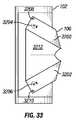
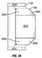
フェアリングは、任意の数の方法において、コンテナ内に収容され得る。例えば、ピラミッド/蛇腹式システムが使用され得、その場合、異なる区画の内部誘導部が各区画の正確な高さにおけるストッパに到達するまで、異なる区画がコンパートメントから持ち上げられるであろう。垂直に沿ったピラミッドの長さは、全区画内で等しいままとなる。横方向幅のみが、高さに伴って変動する(図6、7、および26−29参照)。代替として、地図式システムが使用され得、その場合、フェアリング側面は、展開機構が後退させられるにつれて、フェアリング側面自身の上に折曲されるであろう(図9−11および23−25参照)。代替として、ライザ曲率の一部を形成するであろう、折曲された翼式構成が使用され、定位置に引き延ばされ、スナップ機構を用いて固着され得る(図14、15、および32−34参照)。フェアリングの寸法は、ライザ保管部に嵌合し、渦誘発振動を低減させるように最適化される。ライザに応じて、他の展開解決策も、本概念に適用され得る。 The fairing can be housed in the container in any number of ways. For example, a pyramid / bellows system may be used, in which case the different compartments will be lifted from the compartment until the internal guidance of the different compartments reaches a stop at the exact height of each compartment. The length of the pyramid along the vertical remains the same in all compartments. Only the lateral width varies with height (see FIGS. 6, 7 and 26-29). Alternatively, a cartographic system may be used, in which case the fairing side will be folded over the fairing side itself as the deployment mechanism is retracted (FIGS. 9-11 and 23-25). reference). Alternatively, a folded airfoil configuration that will form part of the riser curvature may be used, stretched in place, and secured using a snap mechanism (FIGS. 14, 15, and 32). -34). The dimensions of the fairing are optimized to fit the riser storage and reduce vortex-induced vibration. Depending on the riser, other deployment solutions may also be applied to the concept.
本発明は、ライザフェアリングを、別個にデッキ上にではなく、ライザに取り付けられたコンテナ内に収容された状態に維持する。一実施形態では、展開に関与する人物は、フェアリングを展開させるために、1つのツールまたは1つの動作のみを使用する必要がある。 The present invention maintains the riser fairing housed in a container attached to the riser rather than separately on the deck. In one embodiment, the person involved in the deployment need only use one tool or one action to deploy the fairing.
本発明の一実施形態は、フェアリング保管ボックスが依然としてライザに取り付けられたまま、ライザが保管されることを可能にするように、保管システム内にはまり、かつ、ライザに取り付けられる折畳式フェアリングである。これは、ライザが展開または後退させられる度に、フェアリングを除去する必要性を排除するであろう。 One embodiment of the present invention is a foldable fair that fits within the storage system and is attached to the riser so as to allow the riser to be stored while the fairing storage box is still attached to the riser. It is a ring. This will eliminate the need to remove the fairing each time the riser is deployed or retracted.
本発明はまた、フェアリングをその格納封入体から展開するために、1つのツールまたは簡略化された動作のみ必要とするため、ライザの展開をより単純かつより安全にする。したがって、ライザを水中へまたは水から外へ稼働させている間、フェアリング区画を定位置に持ち上げる必要性を排除する。 The present invention also makes deployment of the riser simpler and safer since only one tool or simplified operation is required to deploy the fairing from its containment enclosure. Thus, it eliminates the need to lift the fairing section into place while the riser is operating into or out of the water.
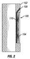
図1−5は、シザージャッキ104を使用して展開される、ライザ102内の折畳式フェアリング100の実施例を図示する。これらの図における折畳式フェアリング100は、ライザ102の境界内に完全に格納される。クロスバー106を備えるシザージャッキ104は、図2および4に実証されるような長ネジ110に接続され得る電力ツールアクセス点108を通して、フェアリング100を展開させるように使用されてもよい。ネジ110が旋回されると、クロスバーが、鋏様の運動で移動して、上部区画の高さを増加させ、それによって、折畳式フェアリング100を展開させる。図5は、展開された折畳式フェアリング100を図示する。 FIGS. 1-5 illustrate an example of a folding fairing 100 in the
図6−15は、折畳式フェアリング100の構造の例示的実施形態を図示する。図6−8は、相互係止フェアリング区画600を使用する、折畳式フェアリング100構造の一実施形態を示す。図6および7では、折畳式フェアリング100の構造は、個々に、601、602、603、604、605、606、607、608と標識されたフェアリング区画600と、ライザ104から引き出され得る端部区画609とから成る。例えば、上部区画609が、ライザ102から引き出されると、上部区画609は、ライザから延在し、フェアリング区画607および608内の定位置に係止するであろう。さらに引き出すと、区画607および608は、区画605および606と定位置に係止する等となるであろう。図6は、保管された折畳式フェアリング100を図示する一方、図7は、展開された折畳式フェアリング100を図示する。フェアリング100は、図8に実証されるような係止スタッド800または他の固着方法の使用によって、定位置に係止してもよい。 6-15 illustrate an exemplary embodiment of the structure of the
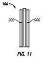
図9−11は、折畳式フェアリング100構造の別の例示的実施形態を図示する。本実施形態では、折畳式フェアリング100は、折曲式区画900から成る。図9は、部分的に展開されたフェアリング100を図示する一方、図10および11は、折畳式フェアリング100の本実施形態の2つの展開された図を図示する。 9-11 illustrate another exemplary embodiment of a folding fairing 100 structure. In the present embodiment, the
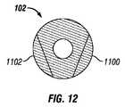
図12および13は、折畳式フェアリング100構造のさらなる実施形態を図示する。本実施形態では、フェアリング100は、ライザ102の2つの切り込み区画1100および1102を備える。2つの切り込み区画1100および1102は、切り込み区画1100および1102が相互に向かって回転可能であるとき、切り込み区画1100および1102の先端が、図13に図示されるように、フェアリングを形成するように当接するように、摺動の終了まで、ライザ102に対して摺動する。区画は、レール滑動部または摺動部(図示せず)を用いて、保管位置において、ライザに取り付けられる。切り込み区画1100および1102の2つの端部区画は、ともに取り付けられ、対向端区画は、展開された位置にあるとき、ライザ102の定位置に係止され、それによって、切り込み区画1100および1102を展開された位置に係止する。この場合、浮揚性モジュールは、2つの区画から成るであろう。内側区画は、その中に切り込まれたいくつかの誘導チャネルとともに、浮揚性材料を格納するであろう。外側区画は、低摩擦材料から作製されるか、または水で潤滑されるかのいずれかであろう、レールを格納するであろう。外側区画はまた、どのように浮力が回転に影響を及ぼすかに応じて、中立性または浮揚性となり得る。これは、下側区画の上部にともにボルトで締められるであろう、2つの半区画から構築されることができる(一方の区画は、フェアリングを格納し、他方は、剥き出しとなる)。 12 and 13 illustrate further embodiments of the folding fairing 100 structure. In this embodiment, the fairing 100 comprises two cut
図14および15は、折畳式フェアリング100の別の実施形態を図示する。本実施形態では、隅角部1404において相互に取り付けられた2つの翼状区画1401および1402は、図15に示されるように、保管位置において、ライザ102に密着させて置かれる。翼状区画1401および1402は、翼状区画1401および1402が枢動することを可能にする手段によって、端部1406において、ライザ102に取り付けられる。折畳式フェアリング100は、翼をライザ102から回転させて、隅角部1408をともに固着することによって展開される。本実施形態はまた、図12および13に関して前述のように、ライザに取り付けられてもよい。 14 and 15 illustrate another embodiment of the
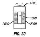
図16−21は、折畳式フェアリング100が、ライザの浮揚性ジョイント1600内に格納される、本発明の実施形態を図示する。図16は、浮揚性ジョイント1600の可撤性区画1602を示す。図17はまた、可撤性区画1602を伴わない、修正された浮揚性ジョイント1600を示す。可撤性区画1602の代わりに、フェアリング保管ボックス1800が、図18に示されるように、浮揚性ジョイント1600に取り付けられる。フェアリング保管ボックスは、フェアリング保管ボックスの上部に位置する1つのドアまたは複数のドアを含む、6つの側面を備えてもよい。フェアリング保管ボックスはまた、折畳式フェアリングの側面が取り付けられるベースプレートのみを備えてもよい。収容形態では、折畳式フェアリングは、フェアリング保管ボックスの側面および上部を形成してもよい。フェアリング保管ボックスは、浮揚性ジョイント1600の周囲においてフェアリングの移動を可能にするために、低摩擦ストラップ1802を用いて、浮揚性ジョイントに取り付けられる。図19は、フェアリング保管ボックス1800から展開された後の折畳式フェアリング100を図示する。図19における流れCは、矢印の方向に流動している。浮揚性ジョイント1600の周縁が、図20に示されるように、フェアリング保管ボックス1800を組み込む区画を通じて維持されるように、付加的浮揚材または浮力中立材2000が、フェアリング保管ボックス1800の周囲に組み込まれてもよい。図21は、付加的材料2000を伴い、折畳式フェアリング100が展開された、浮揚性ジョイントを図示する。図22はまた、可撤性区画1602を有しない、展開された折畳式フェアリング100を示す。図23は、取付用ストラップ1802を有する、閉鎖されたフェアリング保管ボックス1800の実施例を示す。図24は、フェアリング保管ボックス1800から部分的に展開された折畳式フェアリング100の実施例を示す。図25は、フェアリング保管ボックス1800から完全に展開された折畳式フェアリング100の実施例を示す。 FIGS. 16-21 illustrate an embodiment of the present invention in which the
図26−28は、折畳式フェアリング100およびフェアリング保管ボックス1800の別の実施形態を図示する。図26は、フェアリング保管ボックス1800内に収容される、完全に折り畳まれたフェアリングを示す。折畳式フェアリングは、本実施形態では、パネル105から構成される。各パネル105は、フェアリング保管ボックス1800のほぼ同じ高さであり、収容されると密着してはまることを保証する。図27は、部分的に展開された折畳式フェアリング100を図示する。図28は、完全に展開された折畳式フェアリング100を図示する。図29は、本実施形態の完全に展開された折畳式フェアリングの断面を示す。折畳式フェアリング100は、平滑薄片を可能にする、フェアリングパネルの上部間の空間に張架する可鍛性材料パネル2900をさらに含んでもよい。 FIGS. 26-28 illustrate another embodiment of a
図30は、折畳式フェアリング取付部の実施例を図示する。本実施形態では、図1−11および16−29に示されるフェアリング構造のいずれも、固着ストラップチャネル3000によって、ライザ102に取り付けられてもよい。本固着ストラップチャネル3000は、剥き出しのジョイント3002の周囲にしっかりと取り付けられる。閉塞線および抑圧線3004は、図31に示されるように、チャネル内の固着ストラップチャネル貫通孔3100を通して延在する。取付用ストラップ1802は、固着ストラップパネル3000の周囲におけるフェアリングの自由な移動を可能にするように、固着ストラップパネル3000に固着されるであろう。このように、フェアリングは、流れの方向の変化に伴って、ライザ102の周囲を回転するであろう。 FIG. 30 illustrates an example of a folding fairing attachment. In this embodiment, any of the fairing structures shown in FIGS. 1-11 and 16-29 may be attached to the
図32−34は、折畳式フェアリング100構造の別の実施形態を図示する。本実施形態では、折畳式フェアリング100は、図32に示されるように、離間された2つの翼状構造3200および3202から成る。図32は、収容位置における翼状構造3200および3202を示す。翼状構造3200および3202は、翼が、要素3208および3210に示されるように、ライザ102から離れる方へ回転することを可能にする手段によって、ライザに取り付けられる。翼状構造3200および3202は、ラッチノブ3204および3206をさらに備えてもよく、ラッチノブ3204および3206は、翼状パネルの回転を促進し、完全に展開または完全に収容されると、翼状構造を定位置に係止する。図33は、部分的に展開された状態における折畳式フェアリング100を示す。折畳式フェアリングは、展開された折畳式フェアリングの本体を生成するように広がる、折曲されたシートの材料3212をさらに備えてもよい。図34は、完全に展開された状態における折畳式フェアリング100を示す。本実施形態では、折畳式フェアリング100は、フェアリングを付加的格納ボックス内に保管する必要なく、ライザ102を抱持する。 32-34 illustrate another embodiment of the folding fairing 100 structure. In this embodiment, the
図35−38は、2つの層から作製される浮揚性モジュールから成るライザに折畳式ライザフェアリングを取り付けるための別の実施形態を図示する。図12−15および32−34の折畳式ライザフェアリング実施形態は、以下の取付実施形態によって、ライザに取り付けられてもよい。図35は、2つの層、内側層3500および外側層3502から成る浮揚性モジュールを示す。層は、機械的取付部3504によって、ライザ102の周囲にしっかりと取り付けられる、2つの別個の側面から成る。浮揚性ジョイントの内側3500および外側3502層は、浮揚材または浮力中立材から成ってもよい。外側層3502は、折畳式フェアリング100を収納する。 Figures 35-38 illustrate another embodiment for attaching a foldable riser fairing to a riser consisting of a buoyant module made from two layers. The foldable riser fairing embodiments of FIGS. 12-15 and 32-34 may be attached to the riser by the following attachment embodiments. FIG. 35 shows a buoyant module that consists of two layers, an
本発明およびその利点が、詳細に説明されたが、種々の変更、代用、および改変が、添付の請求項によって定義されるような本発明の精神および範囲から逸脱することなく、本明細書において行われ得ることを理解されたい。さらに、本願の範囲は、本明細書に説明されるプロセス、機械、製造、組成物、手段、方法、およびステップの特定の実施形態に限定されることを意図しない。当業者が、本発明の開示から容易に理解するであろうように、本明細書に説明される対応する実施形態と実質的に同一の機能を果たす、または実質的に同一の結果を達成する、現在既存のまたは後に開発されるプロセス、機械、製造、組成物、手段、方法、またはステップが、本発明に従って利用されてもよい。故に、添付の請求項は、そのようなプロセス、機械、製造、組成物、手段、方法、またはステップをその範囲内に含むことが意図される。 Although the invention and its advantages have been described in detail, various changes, substitutions, and modifications can be made herein without departing from the spirit and scope of the invention as defined by the appended claims. It should be understood that this can be done. Furthermore, the scope of the present application is not intended to be limited to the specific embodiments of the processes, machines, manufacture, compositions, means, methods, and steps described herein. As one of ordinary skill in the art will readily appreciate from the disclosure of the present invention, performs substantially the same function or achieves substantially the same result as the corresponding embodiments described herein. Any currently existing or later developed process, machine, manufacture, composition, means, method, or step may be utilized in accordance with the present invention. Accordingly, the appended claims are intended to include within their scope such processes, machines, manufacture, compositions of matter, means, methods, or steps.
Claims (15)
Translated fromJapaneseApplications Claiming Priority (3)
| Application Number | Priority Date | Filing Date | Title |
|---|---|---|---|
| US201161496631P | 2011-06-14 | 2011-06-14 | |
| US61/496,631 | 2011-06-14 | ||
| PCT/US2012/041915WO2012173932A1 (en) | 2011-06-14 | 2012-06-11 | Self contained marine riser fairing |
Related Child Applications (1)
| Application Number | Title | Priority Date | Filing Date |
|---|---|---|---|
| JP2015033630ADivisionJP2015121094A (en) | 2011-06-14 | 2015-02-24 | Self-supporting offshore riser fairing |
Publications (2)
| Publication Number | Publication Date |
|---|---|
| JP2014518341A JP2014518341A (en) | 2014-07-28 |
| JP5721906B2true JP5721906B2 (en) | 2015-05-20 |
Family
ID=47353801
Family Applications (2)
| Application Number | Title | Priority Date | Filing Date |
|---|---|---|---|
| JP2014515902AActiveJP5721906B2 (en) | 2011-06-14 | 2012-06-11 | Free-standing marine riser fairing |
| JP2015033630APendingJP2015121094A (en) | 2011-06-14 | 2015-02-24 | Self-supporting offshore riser fairing |
Family Applications After (1)
| Application Number | Title | Priority Date | Filing Date |
|---|---|---|---|
| JP2015033630APendingJP2015121094A (en) | 2011-06-14 | 2015-02-24 | Self-supporting offshore riser fairing |
Country Status (14)
| Country | Link |
|---|---|
| US (1) | US9011045B2 (en) |
| EP (1) | EP2721245A4 (en) |
| JP (2) | JP5721906B2 (en) |
| KR (1) | KR101530872B1 (en) |
| CN (1) | CN103748311B (en) |
| AP (1) | AP2014007365A0 (en) |
| AU (1) | AU2012271899B2 (en) |
| BR (1) | BR112013031362A2 (en) |
| CA (1) | CA2839243C (en) |
| EA (1) | EA201490017A1 (en) |
| MX (1) | MX343426B (en) |
| MY (1) | MY167099A (en) |
| WO (1) | WO2012173932A1 (en) |
| ZA (1) | ZA201309360B (en) |
Families Citing this family (4)
| Publication number | Priority date | Publication date | Assignee | Title |
|---|---|---|---|---|
| EP3280869A4 (en)* | 2015-04-07 | 2019-01-02 | Ensco International Incorporated | Riser deflection mitigation |
| US10427759B2 (en)* | 2015-08-26 | 2019-10-01 | Pgs Geophysical As | Collapsible fairing |
| WO2019007975A2 (en)* | 2017-07-03 | 2019-01-10 | Subsea 7 Norway As | Offloading hydrocarbons from subsea fields |
| US20200131857A1 (en)* | 2018-10-24 | 2020-04-30 | Ensco International Incorporated | Expandable fairing of weathervaning riser joint |
Family Cites Families (14)
| Publication number | Priority date | Publication date | Assignee | Title |
|---|---|---|---|---|
| US3194204A (en) | 1963-02-01 | 1965-07-13 | Donald A Nichols | Towing cable with fairings |
| DE2149592A1 (en)* | 1971-10-05 | 1973-04-12 | Ver Flugtechnische Werke | FLOW-EFFICIENT COVERING, IN PARTICULAR FOR UNDERWATER CABLES |
| JPS59156996U (en)* | 1983-04-07 | 1984-10-22 | 三菱重工業株式会社 | riser pipe |
| JPS61108698U (en)* | 1984-12-24 | 1986-07-10 | ||
| JPH0452304Y2 (en)* | 1986-02-04 | 1992-12-09 | ||
| CH685989A5 (en)* | 1992-05-12 | 1995-11-30 | Erfis Ag | Foldable structure, in particular Beholtnis. |
| US5984584A (en)* | 1996-05-10 | 1999-11-16 | Shell Oil Company | Fairings for drilling riser control pod hoses |
| US5738034A (en)* | 1996-10-23 | 1998-04-14 | Reading & Bates Development Co. | Fairing system for subsea drilling rigs and method for installation and removal |
| US5722340A (en)* | 1996-12-11 | 1998-03-03 | Mobil Oil Corporation | Fairing for marine risers |
| US6517289B1 (en)* | 2000-09-28 | 2003-02-11 | The United States Of America As Represented By The Secretary Of The Navy | Inflatable vibration reducing fairing |
| US8523492B2 (en)* | 2007-01-05 | 2013-09-03 | Benton Frederick Baugh | Method of installing fairings around vertical pipes |
| JP2010280264A (en)* | 2009-06-03 | 2010-12-16 | Mitsubishi Heavy Ind Ltd | Fluid force reducing structure and cylindrical structure |
| WO2011022332A1 (en)* | 2009-08-17 | 2011-02-24 | Shell Oil Company | Vortex induced vibration suppression systems and methods |
| CN102071883A (en)* | 2010-12-03 | 2011-05-25 | 上海交通大学 | Underwater stand pipe vortex induced vibration inhibiter adopting rotatable cowling |
- 2012
- 2012-06-11JPJP2014515902Apatent/JP5721906B2/enactiveActive
- 2012-06-11CACA2839243Apatent/CA2839243C/ennot_activeExpired - Fee Related
- 2012-06-11KRKR1020147000849Apatent/KR101530872B1/ennot_activeExpired - Fee Related
- 2012-06-11MYMYPI2013702345Apatent/MY167099A/enunknown
- 2012-06-11BRBR112013031362Apatent/BR112013031362A2/ennot_activeIP Right Cessation
- 2012-06-11EAEA201490017Apatent/EA201490017A1/enunknown
- 2012-06-11WOPCT/US2012/041915patent/WO2012173932A1/enactiveApplication Filing
- 2012-06-11MXMX2013014803Apatent/MX343426B/enactiveIP Right Grant
- 2012-06-11CNCN201280028939.8Apatent/CN103748311B/ennot_activeExpired - Fee Related
- 2012-06-11USUS13/493,821patent/US9011045B2/ennot_activeExpired - Fee Related
- 2012-06-11APAP2014007365Apatent/AP2014007365A0/enunknown
- 2012-06-11EPEP12801268.9Apatent/EP2721245A4/ennot_activeWithdrawn
- 2012-06-11AUAU2012271899Apatent/AU2012271899B2/ennot_activeCeased
- 2013
- 2013-12-11ZAZA2013/09360Apatent/ZA201309360B/enunknown
- 2015
- 2015-02-24JPJP2015033630Apatent/JP2015121094A/enactivePending
Also Published As
| Publication number | Publication date |
|---|---|
| KR20140039289A (en) | 2014-04-01 |
| BR112013031362A2 (en) | 2016-11-29 |
| CA2839243A1 (en) | 2012-12-20 |
| AU2012271899A1 (en) | 2013-05-02 |
| ZA201309360B (en) | 2016-07-27 |
| WO2012173932A1 (en) | 2012-12-20 |
| MY167099A (en) | 2018-08-10 |
| AU2012271899B2 (en) | 2015-01-22 |
| CA2839243C (en) | 2016-01-12 |
| US20120321394A1 (en) | 2012-12-20 |
| EP2721245A4 (en) | 2016-01-20 |
| CN103748311B (en) | 2016-06-29 |
| JP2015121094A (en) | 2015-07-02 |
| JP2014518341A (en) | 2014-07-28 |
| EA201490017A1 (en) | 2016-01-29 |
| CN103748311A (en) | 2014-04-23 |
| MX343426B (en) | 2016-11-04 |
| MX2013014803A (en) | 2014-06-04 |
| KR101530872B1 (en) | 2015-06-23 |
| EP2721245A1 (en) | 2014-04-23 |
| AP2014007365A0 (en) | 2014-01-31 |
| NZ618118A (en) | 2014-11-28 |
| US9011045B2 (en) | 2015-04-21 |
Similar Documents
| Publication | Publication Date | Title |
|---|---|---|
| JP6333997B2 (en) | Underwater noise reduction device and deployment system | |
| JP5721906B2 (en) | Free-standing marine riser fairing | |
| CN105143568B (en) | Structure for storage and transport in compact mode | |
| KR101064803B1 (en) | Folding container | |
| JP2008223464A (en) | Collapsible storage system coping with flood | |
| US9394663B2 (en) | Ground anchor | |
| KR20140008580A (en) | Leg protection apparatus of floating structure | |
| CN108263589A (en) | Discharge the method for aerostatics | |
| NZ618118B2 (en) | Self contained marine riser fairing | |
| CN207191371U (en) | One kind anchoring car | |
| EP3092636B1 (en) | Underwater noise abatement apparatus and deployment system | |
| OA16687A (en) | Self contained marine riser fairing. | |
| WO2020075617A1 (en) | Vertical shaft wind power generation device and hydropower generation device accommodated in container | |
| WO2024170906A1 (en) | Noise reduction apparatus and method of its use | |
| KR20140043966A (en) | Heli deck apparatus | |
| US20160159451A1 (en) | Balloon descent decelerator | |
| Lee et al. | Underwater noise abatement apparatus and deployment system | |
| CN105484562B (en) | A kind of application method for the On-vehicle tent for being easy to folding and unfolding | |
| JP2016016827A (en) | Vessel and structure | |
| CN105421877B (en) | A kind of method of work of stabilizing vehicle mounted formula tent | |
| KR101377709B1 (en) | Wind power generator | |
| KR101422235B1 (en) | Leg protection housing apparatus of floating structure | |
| CN107472500A (en) | One kind anchoring car | |
| JP2007070910A (en) | Simple folding type frame structure | |
| KR20140002957A (en) | Floating structure |
Legal Events
| Date | Code | Title | Description |
|---|---|---|---|
| A977 | Report on retrieval | Free format text:JAPANESE INTERMEDIATE CODE: A971007 Effective date:20141217 | |
| A131 | Notification of reasons for refusal | Free format text:JAPANESE INTERMEDIATE CODE: A131 Effective date:20150128 | |
| A521 | Request for written amendment filed | Free format text:JAPANESE INTERMEDIATE CODE: A523 Effective date:20150224 | |
| TRDD | Decision of grant or rejection written | ||
| A01 | Written decision to grant a patent or to grant a registration (utility model) | Free format text:JAPANESE INTERMEDIATE CODE: A01 Effective date:20150323 | |
| A61 | First payment of annual fees (during grant procedure) | Free format text:JAPANESE INTERMEDIATE CODE: A61 Effective date:20150324 | |
| R150 | Certificate of patent or registration of utility model | Ref document number:5721906 Country of ref document:JP Free format text:JAPANESE INTERMEDIATE CODE: R150 | |
| R250 | Receipt of annual fees | Free format text:JAPANESE INTERMEDIATE CODE: R250 | |
| R250 | Receipt of annual fees | Free format text:JAPANESE INTERMEDIATE CODE: R250 |