JP5717898B2 - Fan assembly - Google Patents
Fan assemblyDownload PDFInfo
- Publication number
- JP5717898B2 JP5717898B2JP2014078888AJP2014078888AJP5717898B2JP 5717898 B2JP5717898 B2JP 5717898B2JP 2014078888 AJP2014078888 AJP 2014078888AJP 2014078888 AJP2014078888 AJP 2014078888AJP 5717898 B2JP5717898 B2JP 5717898B2
- Authority
- JP
- Japan
- Prior art keywords
- air
- nozzle
- fan assembly
- passage
- water tank
- Prior art date
- Legal status (The legal status is an assumption and is not a legal conclusion. Google has not performed a legal analysis and makes no representation as to the accuracy of the status listed.)
- Active
Links
- XLYOFNOQVPJJNP-UHFFFAOYSA-NwaterSubstancesOXLYOFNOQVPJJNP-UHFFFAOYSA-N0.000claimsdescription113
- 239000000203mixtureSubstances0.000description7
- 230000005484gravityEffects0.000description3
- 238000007789sealingMethods0.000description3
- 125000006850spacer groupChemical group0.000description3
- 239000003595mistSubstances0.000description2
- 239000007921spraySubstances0.000description2
- 230000004913activationEffects0.000description1
- 239000000853adhesiveSubstances0.000description1
- 230000001070adhesive effectEffects0.000description1
- 238000007599dischargingMethods0.000description1
- 238000003754machiningMethods0.000description1
- 238000004519manufacturing processMethods0.000description1
- 239000002184metalSubstances0.000description1
- 238000000465mouldingMethods0.000description1
- 238000005192partitionMethods0.000description1
- 230000000717retained effectEffects0.000description1
- 230000000007visual effectEffects0.000description1
Images


Classifications
- F—MECHANICAL ENGINEERING; LIGHTING; HEATING; WEAPONS; BLASTING
- F24—HEATING; RANGES; VENTILATING
- F24F—AIR-CONDITIONING; AIR-HUMIDIFICATION; VENTILATION; USE OF AIR CURRENTS FOR SCREENING
- F24F6/00—Air-humidification, e.g. cooling by humidification
- F24F6/12—Air-humidification, e.g. cooling by humidification by forming water dispersions in the air
- F24F6/14—Air-humidification, e.g. cooling by humidification by forming water dispersions in the air using nozzles
- B—PERFORMING OPERATIONS; TRANSPORTING
- B01—PHYSICAL OR CHEMICAL PROCESSES OR APPARATUS IN GENERAL
- B01J—CHEMICAL OR PHYSICAL PROCESSES, e.g. CATALYSIS OR COLLOID CHEMISTRY; THEIR RELEVANT APPARATUS
- B01J19/00—Chemical, physical or physico-chemical processes in general; Their relevant apparatus
- B01J19/08—Processes employing the direct application of electric or wave energy, or particle radiation; Apparatus therefor
- B01J19/10—Processes employing the direct application of electric or wave energy, or particle radiation; Apparatus therefor employing sonic or ultrasonic vibrations
- F—MECHANICAL ENGINEERING; LIGHTING; HEATING; WEAPONS; BLASTING
- F04—POSITIVE - DISPLACEMENT MACHINES FOR LIQUIDS; PUMPS FOR LIQUIDS OR ELASTIC FLUIDS
- F04D—NON-POSITIVE-DISPLACEMENT PUMPS
- F04D25/00—Pumping installations or systems
- F04D25/02—Units comprising pumps and their driving means
- F04D25/08—Units comprising pumps and their driving means the working fluid being air, e.g. for ventilation
- F—MECHANICAL ENGINEERING; LIGHTING; HEATING; WEAPONS; BLASTING
- F04—POSITIVE - DISPLACEMENT MACHINES FOR LIQUIDS; PUMPS FOR LIQUIDS OR ELASTIC FLUIDS
- F04D—NON-POSITIVE-DISPLACEMENT PUMPS
- F04D29/00—Details, component parts, or accessories
- F04D29/40—Casings; Connections of working fluid
- F04D29/42—Casings; Connections of working fluid for radial or helico-centrifugal pumps
- F04D29/44—Fluid-guiding means, e.g. diffusers
- F04D29/441—Fluid-guiding means, e.g. diffusers especially adapted for elastic fluid pumps
- F—MECHANICAL ENGINEERING; LIGHTING; HEATING; WEAPONS; BLASTING
- F04—POSITIVE - DISPLACEMENT MACHINES FOR LIQUIDS; PUMPS FOR LIQUIDS OR ELASTIC FLUIDS
- F04D—NON-POSITIVE-DISPLACEMENT PUMPS
- F04D29/00—Details, component parts, or accessories
- F04D29/40—Casings; Connections of working fluid
- F04D29/52—Casings; Connections of working fluid for axial pumps
- F04D29/54—Fluid-guiding means, e.g. diffusers
- F04D29/541—Specially adapted for elastic fluid pumps
- F04D29/545—Ducts
- F—MECHANICAL ENGINEERING; LIGHTING; HEATING; WEAPONS; BLASTING
- F04—POSITIVE - DISPLACEMENT MACHINES FOR LIQUIDS; PUMPS FOR LIQUIDS OR ELASTIC FLUIDS
- F04D—NON-POSITIVE-DISPLACEMENT PUMPS
- F04D29/00—Details, component parts, or accessories
- F04D29/70—Suction grids; Strainers; Dust separation; Cleaning
- F04D29/701—Suction grids; Strainers; Dust separation; Cleaning especially adapted for elastic fluid pumps
- F04D29/705—Adding liquids
- F—MECHANICAL ENGINEERING; LIGHTING; HEATING; WEAPONS; BLASTING
- F04—POSITIVE - DISPLACEMENT MACHINES FOR LIQUIDS; PUMPS FOR LIQUIDS OR ELASTIC FLUIDS
- F04F—PUMPING OF FLUID BY DIRECT CONTACT OF ANOTHER FLUID OR BY USING INERTIA OF FLUID TO BE PUMPED; SIPHONS
- F04F5/00—Jet pumps, i.e. devices in which flow is induced by pressure drop caused by velocity of another fluid flow
- F04F5/14—Jet pumps, i.e. devices in which flow is induced by pressure drop caused by velocity of another fluid flow the inducing fluid being elastic fluid
- F04F5/16—Jet pumps, i.e. devices in which flow is induced by pressure drop caused by velocity of another fluid flow the inducing fluid being elastic fluid displacing elastic fluids
- F04F5/20—Jet pumps, i.e. devices in which flow is induced by pressure drop caused by velocity of another fluid flow the inducing fluid being elastic fluid displacing elastic fluids for evacuating
- F—MECHANICAL ENGINEERING; LIGHTING; HEATING; WEAPONS; BLASTING
- F24—HEATING; RANGES; VENTILATING
- F24F—AIR-CONDITIONING; AIR-HUMIDIFICATION; VENTILATION; USE OF AIR CURRENTS FOR SCREENING
- F24F1/00—Room units for air-conditioning, e.g. separate or self-contained units or units receiving primary air from a central station
- F24F1/01—Room units for air-conditioning, e.g. separate or self-contained units or units receiving primary air from a central station in which secondary air is induced by injector action of the primary air
- F—MECHANICAL ENGINEERING; LIGHTING; HEATING; WEAPONS; BLASTING
- F24—HEATING; RANGES; VENTILATING
- F24F—AIR-CONDITIONING; AIR-HUMIDIFICATION; VENTILATION; USE OF AIR CURRENTS FOR SCREENING
- F24F13/00—Details common to, or for air-conditioning, air-humidification, ventilation or use of air currents for screening
- F24F13/26—Arrangements for air-circulation by means of induction, e.g. by fluid coupling or thermal effect
- F—MECHANICAL ENGINEERING; LIGHTING; HEATING; WEAPONS; BLASTING
- F24—HEATING; RANGES; VENTILATING
- F24F—AIR-CONDITIONING; AIR-HUMIDIFICATION; VENTILATION; USE OF AIR CURRENTS FOR SCREENING
- F24F3/00—Air-conditioning systems in which conditioned primary air is supplied from one or more central stations to distributing units in the rooms or spaces where it may receive secondary treatment; Apparatus specially designed for such systems
- F24F3/12—Air-conditioning systems in which conditioned primary air is supplied from one or more central stations to distributing units in the rooms or spaces where it may receive secondary treatment; Apparatus specially designed for such systems characterised by the treatment of the air otherwise than by heating and cooling
- F24F3/14—Air-conditioning systems in which conditioned primary air is supplied from one or more central stations to distributing units in the rooms or spaces where it may receive secondary treatment; Apparatus specially designed for such systems characterised by the treatment of the air otherwise than by heating and cooling by humidification; by dehumidification
- F—MECHANICAL ENGINEERING; LIGHTING; HEATING; WEAPONS; BLASTING
- F24—HEATING; RANGES; VENTILATING
- F24F—AIR-CONDITIONING; AIR-HUMIDIFICATION; VENTILATION; USE OF AIR CURRENTS FOR SCREENING
- F24F6/00—Air-humidification, e.g. cooling by humidification
- F24F6/12—Air-humidification, e.g. cooling by humidification by forming water dispersions in the air
- F—MECHANICAL ENGINEERING; LIGHTING; HEATING; WEAPONS; BLASTING
- F24—HEATING; RANGES; VENTILATING
- F24H—FLUID HEATERS, e.g. WATER OR AIR HEATERS, HAVING HEAT-GENERATING MEANS, e.g. HEAT PUMPS, IN GENERAL
- F24H3/00—Air heaters
- F24H3/02—Air heaters with forced circulation
- F24H3/04—Air heaters with forced circulation the air being in direct contact with the heating medium, e.g. electric heating element
- F24H3/0405—Air heaters with forced circulation the air being in direct contact with the heating medium, e.g. electric heating element using electric energy supply, e.g. the heating medium being a resistive element; Heating by direct contact, i.e. with resistive elements, electrodes and fins being bonded together without additional element in-between
- F24H3/0411—Air heaters with forced circulation the air being in direct contact with the heating medium, e.g. electric heating element using electric energy supply, e.g. the heating medium being a resistive element; Heating by direct contact, i.e. with resistive elements, electrodes and fins being bonded together without additional element in-between for domestic or space-heating systems
- F24H3/0417—Air heaters with forced circulation the air being in direct contact with the heating medium, e.g. electric heating element using electric energy supply, e.g. the heating medium being a resistive element; Heating by direct contact, i.e. with resistive elements, electrodes and fins being bonded together without additional element in-between for domestic or space-heating systems portable or mobile
- F—MECHANICAL ENGINEERING; LIGHTING; HEATING; WEAPONS; BLASTING
- F24—HEATING; RANGES; VENTILATING
- F24F—AIR-CONDITIONING; AIR-HUMIDIFICATION; VENTILATION; USE OF AIR CURRENTS FOR SCREENING
- F24F6/00—Air-humidification, e.g. cooling by humidification
- F24F2006/008—Air-humidifier with water reservoir
- F—MECHANICAL ENGINEERING; LIGHTING; HEATING; WEAPONS; BLASTING
- F24—HEATING; RANGES; VENTILATING
- F24F—AIR-CONDITIONING; AIR-HUMIDIFICATION; VENTILATION; USE OF AIR CURRENTS FOR SCREENING
- F24F6/00—Air-humidification, e.g. cooling by humidification
- F24F6/12—Air-humidification, e.g. cooling by humidification by forming water dispersions in the air
- F24F6/14—Air-humidification, e.g. cooling by humidification by forming water dispersions in the air using nozzles
- F24F2006/143—Air-humidification, e.g. cooling by humidification by forming water dispersions in the air using nozzles using pressurised air for spraying
- F—MECHANICAL ENGINEERING; LIGHTING; HEATING; WEAPONS; BLASTING
- F24—HEATING; RANGES; VENTILATING
- F24F—AIR-CONDITIONING; AIR-HUMIDIFICATION; VENTILATION; USE OF AIR CURRENTS FOR SCREENING
- F24F2221/00—Details or features not otherwise provided for
- F24F2221/28—Details or features not otherwise provided for using the Coanda effect
- Y—GENERAL TAGGING OF NEW TECHNOLOGICAL DEVELOPMENTS; GENERAL TAGGING OF CROSS-SECTIONAL TECHNOLOGIES SPANNING OVER SEVERAL SECTIONS OF THE IPC; TECHNICAL SUBJECTS COVERED BY FORMER USPC CROSS-REFERENCE ART COLLECTIONS [XRACs] AND DIGESTS
- Y02—TECHNOLOGIES OR APPLICATIONS FOR MITIGATION OR ADAPTATION AGAINST CLIMATE CHANGE
- Y02B—CLIMATE CHANGE MITIGATION TECHNOLOGIES RELATED TO BUILDINGS, e.g. HOUSING, HOUSE APPLIANCES OR RELATED END-USER APPLICATIONS
- Y02B30/00—Energy efficient heating, ventilation or air conditioning [HVAC]
- Y02B30/54—Free-cooling systems
- Y—GENERAL TAGGING OF NEW TECHNOLOGICAL DEVELOPMENTS; GENERAL TAGGING OF CROSS-SECTIONAL TECHNOLOGIES SPANNING OVER SEVERAL SECTIONS OF THE IPC; TECHNICAL SUBJECTS COVERED BY FORMER USPC CROSS-REFERENCE ART COLLECTIONS [XRACs] AND DIGESTS
- Y02—TECHNOLOGIES OR APPLICATIONS FOR MITIGATION OR ADAPTATION AGAINST CLIMATE CHANGE
- Y02B—CLIMATE CHANGE MITIGATION TECHNOLOGIES RELATED TO BUILDINGS, e.g. HOUSING, HOUSE APPLIANCES OR RELATED END-USER APPLICATIONS
- Y02B30/00—Energy efficient heating, ventilation or air conditioning [HVAC]
- Y02B30/70—Efficient control or regulation technologies, e.g. for control of refrigerant flow, motor or heating
Landscapes
- Engineering & Computer Science (AREA)
- Mechanical Engineering (AREA)
- General Engineering & Computer Science (AREA)
- Chemical & Material Sciences (AREA)
- Combustion & Propulsion (AREA)
- Dispersion Chemistry (AREA)
- Physics & Mathematics (AREA)
- Fluid Mechanics (AREA)
- Health & Medical Sciences (AREA)
- General Health & Medical Sciences (AREA)
- Toxicology (AREA)
- Organic Chemistry (AREA)
- Chemical Kinetics & Catalysis (AREA)
- Thermal Sciences (AREA)
- Jet Pumps And Other Pumps (AREA)
- Structures Of Non-Positive Displacement Pumps (AREA)
- Air Humidification (AREA)
- Nozzles (AREA)
- Electrostatic Spraying Apparatus (AREA)
Description
Translated fromJapanese本発明は、ファン組立体に関する。好ましい実施形態では、本発明は、部屋又はオフィスなどの家庭環境内において、湿り空気流、及び湿り空気を分散させる空気流を発生させるための加湿装置を提供する。本発明は、環境内で温かい、冷たい、香りを付けた、又はイオン化した空気流を分散させるために使用することもできる。 The present invention relates to a fan assembly. In a preferred embodiment, the present invention provides a humidifier for generating a humid air flow and an air flow that disperses the humid air in a home environment such as a room or office. The present invention can also be used to disperse warm, cold, scented or ionized air streams in the environment.
家庭用加湿装置は、一般に、所定量の水を蓄えるための水タンクを含むケーシングと、ケーシングの空気ダクトを通る空気流を生み出すためのファンとを有する携帯型電気器具の形をしている。蓄えられた水は、通常は重力により、受け取った水から水滴を発生させるための噴霧装置へ運ばれる。この噴霧装置は、変換器などの高周波振動装置の形をとることができる。水滴は、空気ダクトを通過する空気流に入り込み、これにより環境内にミストが放出される。この電気器具は、環境内の空気の相対湿度を検出するためのセンサを含むことができる。このセンサは、検出した相対湿度を示す信号を駆動回路に出力し、この駆動回路は、環境内の空気の相対湿度を所望のレベル付近に維持するように変換器を制御する。通常は、検出した相対湿度が所望のレベルよりも約5%高くなると変換器の作動が停止し、検出した相対湿度が所望のレベルよりも約5%低くなると再始動する。 A home humidifier is generally in the form of a portable appliance having a casing containing a water tank for storing a predetermined amount of water and a fan for creating an air flow through the air duct of the casing. The stored water is carried by gravity, usually by gravity, to a spray device for generating water droplets from the received water. The spray device can take the form of a high frequency vibration device such as a transducer. The water droplets enter the air stream that passes through the air duct, thereby releasing mist into the environment. The appliance can include a sensor for detecting the relative humidity of the air in the environment. The sensor outputs a signal indicating the detected relative humidity to the drive circuit, which controls the converter to maintain the relative humidity of the air in the environment near a desired level. Normally, the converter stops operating when the detected relative humidity is about 5% higher than the desired level and restarts when the detected relative humidity is about 5% lower than the desired level.
このような加湿器から放出される空気の流量は、例えば、毎秒1〜2リットルという比較的低い傾向にあるので、湿り空気が室内に分散される速度は非常に遅いものとなり得る。さらに、加湿器の局所環境内における空気の相対湿度は、ユーザの局所環境内における空気の相対湿度と比較して比較的急速に上昇するので、センサにより検出される相対湿度は、少なくとも最初は、ユーザの近くの空気の相対湿度を示しているわけではない。この結果、ユーザの局所環境内における空気の相対湿度が所望のレベルを著しく下回ったときに変換器の作動が停止することがある。湿り空気が室内に分散する速度が比較的遅いので、検出される相対湿度が変換器の作動を再開させるレベルまで下がるには、ある程度の時間がかかることがある。この結果、ユーザの局所環境内における空気の相対湿度が所望のレベルに達するのに長時間を要することがある。 Since the flow rate of air discharged from such a humidifier tends to be relatively low, for example, 1 to 2 liters per second, the speed at which the humid air is dispersed in the room can be very slow. Furthermore, since the relative humidity of the air in the humidifier's local environment rises relatively quickly compared to the relative humidity of the air in the user's local environment, the relative humidity detected by the sensor is at least initially It does not indicate the relative humidity of the air near the user. As a result, the transducer may stop operating when the relative humidity of the air in the user's local environment is significantly below a desired level. Because the rate at which the humid air is dispersed in the room is relatively slow, it may take some time for the detected relative humidity to drop to a level at which to resume operation of the transducer. As a result, it may take a long time for the relative humidity of the air in the user's local environment to reach a desired level.
国際公開第2010/100462号には、湿り空気を大気中に放出するための加湿器と、この加湿器の前に位置するファン組立体とを含み、ファン組立体が、空気流を生み出すためのモータ駆動式羽根車を収容する本体と、この本体に装着され、空気流を受け入れる内部通路及び空気流を放出するための空気出口を含む環状ノズルとを有する加湿装置が記載されている。ノズルはボアを定め、このボアを通じて、ノズル外部からの空気と加湿器から放出された湿り空気の両方が、口部から放出された空気流によって引き込まれる。
加湿器の出口は、ノズルのボアの最下部と同じレベルに位置する。加湿器から放出された湿り空気を、ファン組立体によって生じた空気流内に同伴させることにより、湿り空気を、加湿器から最大数メートルの距離まで急速に運ぶことができる。これにより、加湿器からこの距離に位置するユーザが、その局所環境内における空気の相対湿度の急速な上昇を体感できるようにすることができる。WO 2010/100462 includes a humidifier for releasing humid air into the atmosphere and a fan assembly located in front of the humidifier, the fan assembly for generating an air flow A humidification device is described having a main body that houses a motor driven impeller, and an annular nozzle that is attached to the main body and includes an internal passage for receiving an air flow and an air outlet for discharging the air flow. The nozzle defines a bore through which both the air from outside the nozzle and the humid air released from the humidifier are drawn by the air flow emitted from the mouth.
The outlet of the humidifier is located at the same level as the bottom of the nozzle bore. By entraining the humid air released from the humidifier within the air flow generated by the fan assembly, the humid air can be rapidly carried up to a distance of up to several meters from the humidifier. Thereby, the user who is located at this distance from the humidifier can experience a rapid increase in the relative humidity of the air in the local environment.
第1の態様では、本発明は、
ノズルと、
前記ノズルが装着された本体と、
を備えたファン組立体であって、
前記ノズルが、少なくとも1つの第1の空気入口と、少なくとも1つの第1の空気出口と、前記少なくとも1つの第1の空気入口から前記少なくとも1つの第1の空気出口へ空気を運ぶための第1の内部通路と、少なくとも1つの第2の空気入口と、少なくとも1つの第2の空気出口と、前記少なくとも1つの第2の空気入口から前記少なくとも1つの第2の空気出口へ空気を運ぶための第2の内部通路と有し、前記ノズルがボアを定め、該ボアの周囲を前記2つの内部通路が延び、前記ボアを通じて、前記2つの空気出口から放出された空気によってファン組立体の外部からの空気が引き込まれ、
前記本体が、前記第1の内部通路を通る第1の空気流及び前記第2の内部通路を通る第2の空気流を発生させるための流れ発生手段と、前記第1の空気流を前記少なくとも1つの第1の空気入口へ運ぶための第1の空気通路と、前記第2の空気流を前記少なくとも1つの第2の空気入口へ運ぶための、前記流れ発生手段から下流に前記第1の空気通路からの空気を受け入れるように配置された第2の空気通路を含み、
前記第2の空気流の温度、湿度、組成及び電荷のうちの1つを変化させるための手段をさらに備える、
ことを特徴とするファン組立体を提供する。In a first aspect, the present invention provides:
A nozzle,
A main body to which the nozzle is mounted;
A fan assembly comprising:
The nozzle has at least one first air inlet, at least one first air outlet, and a first for carrying air from the at least one first air inlet to the at least one first air outlet. One internal passage, at least one second air inlet, at least one second air outlet, and for carrying air from the at least one second air inlet to the at least one second air outlet. A second internal passage, wherein the nozzle defines a bore, the two internal passages extend around the bore, and air is discharged from the two air outlets through the bore to the outside of the fan assembly. The air from
The body includes flow generating means for generating a first air flow through the first internal passage and a second air flow through the second internal passage; and A first air passage for carrying one first air inlet, and the first air passage downstream from the flow generating means for carrying the second air flow to the at least one second air inlet. A second air passage arranged to receive air from the air passage;
Means for changing one of temperature, humidity, composition and charge of the second air stream;
A fan assembly is provided.
図示の実施形態では、ファン組立体が、第2の空気流を加湿するための加湿器を含むが、このファン組立体は、第2の空気流の別のパラメータを変化させるための加熱器、冷却器、空気清浄器及びイオン化装置をうちの1つを代わりに含むこともできる。 In the illustrated embodiment, the fan assembly includes a humidifier for humidifying the second air flow, the fan assembly comprising a heater for changing another parameter of the second air flow; A cooler, air purifier, and ionizer may be included instead.
本発明のファン組立体を、加湿した空気流を放出するために使用した場合と、国際公開第2010/100462号に記載される加湿装置との違いは、本発明では、ファン組立体のノズルが、湿った第2の空気流と、この湿り空気流を環境内へ運ぶ第1の空気流の両方を放出するように配置されている点にある。対照的に、国際公開第2010/100462号では、ファン組立体の後方に位置する加湿装置の出口から湿り空気流が放出され、ファン組立体によって生じる空気流の下方部分に同伴される。従って、本発明では、ノズルの1又はそれ以上の異なる空気出口から湿り空気流が放出されるようにすることができる。これらの空気出口を、例えばノズルのボアの周囲に配置して、湿り空気流が第1の空気流内で比較的均一に分散されるようにすることができる。上述の第2の空気流のパラメータの1つを変化させるための手段は、ファン組立体の本体内に位置することが好ましい。第2の空気流の湿度を変化させる構成要素を本体内に配置することにより、ファン組立体の外観がコンパクトになり、構成要素の数が減少し、従って製造コストを削減することができる。 The difference between the case where the fan assembly of the present invention is used to release a humidified air flow and the humidification device described in WO2010 / 100462 is that the nozzle of the fan assembly is , Being arranged to emit both a moist second air stream and a first air stream that carries the moist air stream into the environment. In contrast, in WO 2010/100462, a humid air flow is released from the outlet of a humidifier located behind the fan assembly and is entrained in the lower part of the air flow generated by the fan assembly. Thus, the present invention allows a humid air stream to be emitted from one or more different air outlets of the nozzle. These air outlets can be arranged, for example, around the bore of the nozzle so that the moist air stream is distributed relatively uniformly within the first air stream. The means for changing one of the second airflow parameters described above is preferably located within the body of the fan assembly. By placing components in the body that change the humidity of the second air flow, the appearance of the fan assembly is compact, the number of components is reduced, and thus manufacturing costs can be reduced.
ファン組立体の本体は、第1の空気流をノズルの(単複の)第1の空気入口へ運ぶための第1の空気通路と、第2の空気流をノズルの(単複の)第2の空気入口へ運ぶための第2の空気通路とを含むことができる。従って、上述した第2の空気流のパラメータを変化させるための手段は、少なくとも部分的に第2の空気通路内に位置することもできる。 The body of the fan assembly includes a first air passage for carrying a first air stream to the first air inlet (s) of the nozzle and a second air stream (s) of the nozzle. A second air passage for carrying to the air inlet. Thus, the means for changing the parameters of the second air flow described above can also be located at least partly in the second air passage.
本体は、第1の空気流をファン組立体内に流入できるようにするための空気流入口を含むことができる。空気流入口は、単一の開口を含むこともできるが、複数の開口を含むことが好ましい。これらの開口は、本体の外面の一部を形成するメッシュ、グリル又はその他の成形した構成要素によって設けることができる。 The body can include an air inlet for allowing a first air stream to flow into the fan assembly. The air inlet can include a single opening, but preferably includes a plurality of openings. These openings can be provided by a mesh, grill or other molded component that forms part of the outer surface of the body.
第1の空気通路は、空気流入口からノズルの(単複の)第1の空気入口へ延びることが好ましい。第2の空気通路は、第1の空気通路からの空気を受け入れるように配置される。接合部を流れ発生手段から下流に配置する利点は、流れ発生手段が、単一の羽根車と、この羽根車から下流に第1及び第2の空気流に分割された空気流を発生させるためのモータとを含むことができる点である。この羽根車は、混成流羽根車であっても、又は軸方向羽根車であってもよい。 The first air passage preferably extends from the air inlet to the first air inlet (s) of the nozzle. The second air passage is arranged to receive air from the first air passage. The advantage of arranging the joint downstream from the flow generating means is that the flow generating means generates a single impeller and an air flow that is divided into first and second air flows downstream from the impeller. The motor can be included. This impeller may be a mixed flow impeller or an axial impeller.
第1の空気流は、第1の空気流量で放出され、第2の空気流は、第1の空気流量よりも低い第2の空気流量で放出されることが好ましい。第1の空気流量は、可変空気流量であってもよく、従って第2の空気流量は、第1の空気流量によって変化してもよい。 Preferably, the first air flow is released at a first air flow rate and the second air flow is released at a second air flow rate that is lower than the first air flow rate. The first air flow rate may be a variable air flow rate, and thus the second air flow rate may vary with the first air flow rate.
空気通路は、とりわけ、空気流入口の場所及び第2の空気流の湿度又は温度を変化させるための選択手段の性質に応じて、本体内にあらゆる所望の構成で配置することができる。本体のサイズを縮小させるために、第1の空気通路を第2の空気通路に隣接させて配置してもよい。各空気通路は本体内を垂直に延び、第2の空気通路は第1の空気通路の前で垂直に延びることができる。 The air passage can be arranged in any desired configuration within the body, depending on, inter alia, the location of the air inlet and the nature of the selection means for changing the humidity or temperature of the second air flow. In order to reduce the size of the main body, the first air passage may be disposed adjacent to the second air passage. Each air passage can extend vertically through the body and the second air passage can extend vertically in front of the first air passage.
第1の(単複の)空気出口は、第2の空気流が第1の空気流内でノズルから離れて運ばれるように、第2の(単複の)空気出口の後方に位置することが好ましい。各内部通路は環状であることが好ましい。ノズルのこれら2つの内部通路をノズルのそれぞれの構成要素によって定め、これらを組み立て中に互いに接続することができる。或いは、ノズルの共通の内壁と外壁の間に位置する隔壁又はその他の分割部材によって、ノズルの内部通路を分離することもできる。上述したように、第1の内部通路は第2の内部通路から分離されることが好ましいが、第1の内部通路から第2の内部通路に比較的少量の空気を抽気して、第2の空気流がノズルの(単複の)第2の空気出口を通るように促すこともできる。 The first (s) air outlet is preferably located behind the second (s) air outlet so that the second air stream is carried away from the nozzle in the first air stream. . Each internal passage is preferably annular. These two internal passages of the nozzle can be defined by respective components of the nozzle and can be connected to each other during assembly. Alternatively, the internal passage of the nozzle can be separated by a partition wall or other dividing member located between the common inner wall and outer wall of the nozzle. As described above, the first internal passage is preferably separated from the second internal passage, but a relatively small amount of air is extracted from the first internal passage to the second internal passage, It is also possible to encourage the air flow to pass through the second air outlet (s) of the nozzle.
第1の空気流の流量は、第2の空気流の流量よりも大きいことが好ましいので、ノズルの第1の内部通路の容量は、ノズルの第2の内部通路の容量よりも大きいことが好ましい。 Since the flow rate of the first air flow is preferably larger than the flow rate of the second air flow, the capacity of the first internal passage of the nozzle is preferably larger than the capacity of the second internal passage of the nozzle. .
ノズルは、単一の連続する第1の空気出口を含むことができ、この空気出口はノズルのボアの周囲に延びることが好ましく、またボアの軸を中心とすることが好ましい。或いは、ノズルは、ノズルのボアの周囲に配置された複数の第1の空気出口を含むこともできる。例えば、この第1の空気出口をボアの両側に配置することができる。(単複の)第1の空気出口は、ボアの少なくとも前部を通じて空気を放出するように配置されることが好ましい。(単複の)第1の空気出口は、ボアの一部を定める面上に空気を放出し、ボアを通じて引き込まれる空気容量を、第1の空気出口から放出される空気によって最大にするように配置することができる。或いは、(単複の)第1の空気出口を、ノズルの端面から空気流を放出するように配置してもよい。 The nozzle may include a single continuous first air outlet, which preferably extends around the nozzle bore and is centered about the axis of the bore. Alternatively, the nozzle may include a plurality of first air outlets disposed around the nozzle bore. For example, this first air outlet can be located on both sides of the bore. The first air outlet (s) are preferably arranged to release air through at least the front of the bore. The first air outlet (s) is arranged to release air onto a surface defining a part of the bore and maximize the air volume drawn through the bore by the air discharged from the first air outlet. can do. Alternatively, the first air outlet (s) may be arranged to release an air flow from the end face of the nozzle.
ノズルの(単複の)第2の空気出口は、このノズルの面上に第2の空気流を放出するように配置することができる。或いは、(単複の)第2の空気出口をノズルの前端に配置し、ノズルの面から離れて空気を放出するように配置することもできる。従って、(単複の)第1の空気出口を、(単複の)第2の空気出口に隣接させて配置することができる。ノズルは、ノズルの軸の周囲に延びることができる単一の連続する第2の空気出口を含むことができる。或いは、ノズルが、ノズルの前端の周囲に配置できる複数の第2の空気出口を含むこともできる。例えば、第2の空気出口を、ノズル前端の両側に配置することができる。複数の空気出口の各々は、例えば、スロット、複数の線形に配列されたスロット、又は複数の開口などの、1又はそれ以上の開口を含むことができる。第1の空気出口は、第2の空気出口に対して平行に延びることができる。 The second air outlet (s) of the nozzle can be arranged to emit a second air stream over the surface of the nozzle. Alternatively, the second air outlet (s) can be arranged at the front end of the nozzle and can be arranged to release air away from the nozzle face. Thus, the first air outlet (s) can be positioned adjacent to the second air outlet (s). The nozzle can include a single continuous second air outlet that can extend around the axis of the nozzle. Alternatively, the nozzle can include a plurality of second air outlets that can be disposed around the front end of the nozzle. For example, the second air outlet can be arranged on both sides of the nozzle front end. Each of the plurality of air outlets can include one or more openings, such as, for example, a slot, a plurality of linearly arranged slots, or a plurality of openings. The first air outlet can extend parallel to the second air outlet.
好ましい実施形態では、ファン組立体が、ノズルから第2の空気流が放出される前に、この第2の空気流の湿度を増加させるように構成された加湿システムを含む。外観がコンパクトで構成要素の数が少ないファン組立体を提供するために、加湿システムの少なくとも一部をノズルの下方に配置することができる。加湿システムの少なくとも一部を、羽根車及びモータの下方に配置することもできる。例えば、水を霧化するための変換器をノズルの下方に配置することができる。この変換器は、モータを制御するコントローラによって制御することができる。第2の空気通路は、水タンクからの水を受け入れるための容器上に、及び容器内に存在する水を霧化するための変換器上に第2の空気流を運ぶように配置することができる。 In a preferred embodiment, the fan assembly includes a humidification system configured to increase the humidity of the second air stream before the second air stream is discharged from the nozzle. In order to provide a fan assembly that is compact in appearance and has a small number of components, at least a portion of the humidification system can be positioned below the nozzle. At least a part of the humidification system can also be arranged below the impeller and the motor. For example, a transducer for atomizing water can be placed below the nozzle. This converter can be controlled by a controller that controls the motor. The second air passage may be arranged to carry a second air stream on the container for receiving water from the water tank and on the transducer for atomizing the water present in the container. it can.
本体は、加湿手段に水を供給するための取り外し可能な水タンクを含むことができる。外観がコンパクトな本体を提供するために、水タンクは、流れ発生手段の周囲に延びることが好ましい。好ましい実施形態では、水タンクが流れ発生手段を取り囲む。水タンクは、第1の空気通路の少なくとも一部及び第2の空気通路の少なくとも一部を取り囲むことができる。本体は、ファン組立体に入る空気が通過する空気入口を含む基部を含むことができ、この基部上に水タンクを装着することができる。基部及び水タンクは、円筒形の外面を各々が有し、この基部及び水タンクの外面は、実質的に同じ半径であることが好ましい。このことは、ファン組立体のコンパクトな外観にさらに寄与することができる。 The body can include a removable water tank for supplying water to the humidifying means. In order to provide a body that is compact in appearance, the water tank preferably extends around the flow generating means. In a preferred embodiment, a water tank surrounds the flow generating means. The water tank can surround at least a portion of the first air passage and at least a portion of the second air passage. The body can include a base that includes an air inlet through which air entering the fan assembly passes, and a water tank can be mounted on the base. The base and water tank each have a cylindrical outer surface, preferably the outer surface of the base and water tank are substantially the same radius. This can further contribute to the compact appearance of the fan assembly.
第2の態様では、本発明は、
ノズルと、
前記ノズルが装着された本体と、
を備え、
前記ノズルが、少なくとも1つの第1の空気入口と、少なくとも1つの第1の空気出口と、前記少なくとも1つの第1の空気入口から前記少なくとも1つの第1の空気出口へ空気を運ぶための第1の内部通路と、少なくとも1つの第2の空気入口と、少なくとも1つの第2の空気出口と、前記少なくとも1つの第2の空気入口から前記少なくとも1つの第2の空気出口へ空気を運ぶための第2の内部通路と有し、前記ノズルがボアを定め、このボアを通じて、前記2つの空気出口から放出された空気によってファン組立体の外部からの空気が引き込まれ、
前記本体が、基部と、この基部に装着された水タンクとを含み、前記基部が、前記第1の内部通路を通る第1の空気流及び前記第2の内部通路を通る第2の空気流を発生させるための流れ発生手段と、前記水タンクから水を受け取るための容器と、この容器内に存在する水を霧化するための変換器と、前記第1の空気流を前記少なくとも1つの第1の空気入口へ運ぶための第1の空気通路と、前記第2の空気流を前記少なくとも1つの第2の空気入口へ運ぶための第2の空気通路とを含み、前記水タンクが、好ましくは前記流れ発生手段の周囲に延びる、
ことを特徴とする加湿装置を提供する。第2の空気通路は、流れ発生手段から下流で第1の空気通路に接続されることが好ましい。流れ発生手段は、羽根車と、この羽根車を駆動するためのモータとを含むことが好ましい。In a second aspect, the present invention provides:
A nozzle,
A main body to which the nozzle is mounted;
With
The nozzle has at least one first air inlet, at least one first air outlet, and a first for carrying air from the at least one first air inlet to the at least one first air outlet. One internal passage, at least one second air inlet, at least one second air outlet, and for carrying air from the at least one second air inlet to the at least one second air outlet. And the nozzle defines a bore through which air from the outside of the fan assembly is drawn by the air released from the two air outlets,
The main body includes a base and a water tank attached to the base, and the base has a first air flow passing through the first internal passage and a second air flow passing through the second internal passage. A flow generating means for generating water, a container for receiving water from the water tank, a transducer for atomizing water present in the container, and the first air flow into the at least one A first air passage for carrying to the first air inlet; and a second air passage for carrying the second air flow to the at least one second air inlet, the water tank comprising: Preferably extending around the flow generating means,
A humidifying device is provided. The second air passage is preferably connected to the first air passage downstream from the flow generating means. The flow generating means preferably includes an impeller and a motor for driving the impeller.
羽根車は、混成流羽根車の形であることが好ましい。第1及び第2の空気流を発生させるために混成流羽根車を使用する利点は、回転する混成流羽根車から放出される空気流の圧力が、例えば、基部を通る空気流が第1の空気流と第2の空気流に分かれるとき、及び第2の空気流が、第2の空気通路に沿ってノズルの少なくとも1つの第2の空気入口へ移動するときに遭遇するあらゆる流れ障害に第2の空気流が打ち勝てるほど十分に高い点である。 The impeller is preferably in the form of a mixed flow impeller. The advantage of using a mixed flow impeller to generate the first and second airflows is that the pressure of the airflow discharged from the rotating mixed flow impeller is such that the airflow through the base is the first. Any flow obstruction encountered when splitting into an air flow and a second air flow, and when the second air flow moves along the second air passage to at least one second air inlet of the nozzle. The point is high enough that the airflow of 2 can be overcome.
第3の態様では、本発明は、
本体と、
この本体上に装着されたノズルと、
を備えた加湿装置であって、
前記本体が、混成流羽根車と、この羽根車を駆動させて空気流を発生させるためのモータと、前記空気流を加湿するための加湿手段へ前記空気流を運ぶための第1のダクトと、湿り空気流を前記ノズルへ運ぶための第2のダクトとを含み、
前記ノズルが、前記湿り空気流を受け入れるための少なくとも1つの空気入口と、前記湿り空気流を放出するための少なくとも1つの空気出口とを含み、前記ノズルが、このノズルから放出された空気によって前記装置の外側からの空気を引き込む開口部の周囲に延びる、
ことを特徴とする加湿装置を提供する。In a third aspect, the present invention provides:
The body,
A nozzle mounted on this body,
A humidifying device comprising:
The body includes a mixed flow impeller, a motor for driving the impeller to generate an air flow, and a first duct for carrying the air flow to a humidifying means for humidifying the air flow; A second duct for carrying a stream of moist air to the nozzle,
The nozzle includes at least one air inlet for receiving the moist air stream and at least one air outlet for releasing the moist air stream, the nozzle being driven by the air discharged from the nozzle. Extending around an opening that draws in air from outside the device,
A humidifying device is provided.
本体は、羽根車を収容する羽根車ハウジングを備えることができる。この羽根車ハウジングは、空気入口と空気出口とを備え、第1のダクトは、羽根車ハウジングの空気出口からすぐ下流に位置する入口ポートを備えることができる。 The body can include an impeller housing that houses the impeller. The impeller housing may include an air inlet and an air outlet, and the first duct may include an inlet port located immediately downstream from the air outlet of the impeller housing.
本発明の第1の態様に関連して上述した特徴は、本発明の第2及び第3の態様の各々にも等しく適用可能であり、逆もまた同様である。 Features described above in connection with the first aspect of the invention are equally applicable to each of the second and third aspects of the invention, and vice versa.
以下、添付図面を参照しながら、本発明の実施形態をほんの一例として説明する。 Embodiments of the present invention will now be described by way of example only with reference to the accompanying drawings.
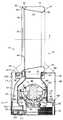
図1〜図3は、ファン組立体10の外観図である。大まかに言えば、このファン組立体10は、ファン組立体10に入る空気が通過する空気入口を含む本体12、及び本体12上に装着された環状ケーシングの形のノズル14を含み、このノズル14は、ファン組立体10から空気を放出するための複数の空気出口を含む。 1 to 3 are external views of the
ノズル14は、2つの異なる空気流を放出するように配置される。ノズル14は、後側部分16、及びこの後側部分16に接続された前側部分18を含む。各部分16、18は環状の形であり、これらはノズル14のボア20の周囲に延びる。ボア20は、各部分16、18の中心がボア20の軸X上に位置するように、ノズル14の中心を貫いて延びる。 The
この例では、各部分16、18が、ボア20の両側に位置する2つのほぼ直線部分と、この直線部分の上端を接合する湾曲した上部と、直線部分の下端を接合する湾曲した下部とを含むという点で「レーストラック」形状を有する。しかしながら、部分16、18は、あらゆる所望の形状を有することができ、例えば、円形又は長円形であってもよい。この実施形態では、ノズル14の高さの方がノズルの幅よりも大きいが、ノズル14の幅の方がノズルの高さよりも大きくなるようにノズル14を構成することもできる。 In this example, each
ノズル14の各部分16、18は、空気流のそれぞれ一方が通る流路を定める。この実施形態では、ノズル14の後側部分16が、ノズル14を通過する第1の空気流が通る第1の空気流路を定め、ノズル14の前側部分18が、ノズル14を通過する第2の空気流が通る第2の空気流路を定める。 Each
図4も参照すると分かるように、ノズル14の後側部分16は、環状内側ケーシング部分24に接続されてこの周囲に延びる環状外側ケーシング部分22を含む。各ケーシング部分22、24は、ボア軸Xの周囲に延びる。各ケーシング部分は、複数の接続部品から形成することができるが、この実施形態では、各ケーシング部分22、24がそれぞれの単一の成形部品から形成される。図7及び図8も参照すると分かるように、第1の外側ケーシング部分22の後部26は、ボア軸Xの方向に内向きに湾曲して、ノズル14の後端及びボア20の後部を定める。組み立て中、第1の外側ケーシング部分22の後部26の端部は、例えば接着剤を使用して内側ケーシング部分24の後端に接続される。第1の外側ケーシング部分22は、ノズル14の第1の空気入口30を定める管状基部28を含む。 As can also be seen with reference to FIG. 4, the
ノズル14の前側部分18は、環状前側ケーシング部分34に接続されてこの周囲に延びる環状第2の外側ケーシング部分32を含む。この場合も、各ケーシング部分32、34はボア軸Xの周囲に延び、複数の接続部品から形成することができるが、この実施形態では、各ケーシング部分32、34がそれぞれ単一の成形部品から形成される。この例では、前側ケーシング部分34が、外側ケーシング部分22の前端に接続された後部36と、形状がほぼ裁頭円錐形の、ボア軸Xから離れて後部36から外向きに広がる前部38とを含む。前側ケーシング部分34は、内側ケーシング部分24と一体化することができる。第2の外側ケーシング部分32は、形状がほぼ円筒形であり、第1の外側ケーシング部分22と前側ケーシング部分34の前端との間に延びる。第2の外側ケーシング部分32は、ノズル14の第2の空気入口42を定める管状基部40を含む。 The
ケーシング部分24、34は、ノズル14の第1の空気出口44を一体に定める。第1の空気出口44は、内側ケーシング部分24の表面と前側ケーシング部分34の後部36の表面を、第1の空気出口44が、ノズル14の前端から空気を放出するよう配置されるように重ね合わせ又は向かい合わせることによって定められる。この第1の空気出口44は、環状スロットの形をしており、ボア軸Xの周囲に0.5mm〜5mmの比較的一定の幅を有する。この例では、第1の空気出口44が約1mmの幅を有する。内側ケーシング部分24、34が、それぞれの構成要素から形成される場合、ケーシング部分24、34の重なり合った部分を離して付勢するためのスペーサ46を第1の空気出口44の周囲に離間させて、第1の空気出口44の幅を制御することができる。これらのスペーサは、ケーシング部分24、34のいずれかと一体化することができる。ケーシング部分24、34が単一の構成要素から形成される場合、スペーサ46を、内側ケーシング部分24と前側ケーシング部分34を互いに接続するためのフィンに置き換えて、これを第1の空気出口44の周囲に離間させる。 The
ノズル14は、第1の空気流を第1の空気入口30から第1の空気出口44へ運ぶための環状の第1の内部通路48を定める。第1の内部通路48は、第1の外側ケーシング部分22の内面と内側ケーシング部分24の内面によって定められる。先細になった環状口部50が、第1の空気流を第1の空気出口44へ導く。従って、ノズル14を通る第1の空気流路は、第1の空気入口30、第1の内部通路48、口部50及び第1の空気出口44から形成されると考えることができる。 The
前側ケーシング部分34は、ノズル14の複数の第2の空気出口52を定める。第2の空気出口52も、例えば、成形又は機械加工によって、ノズル14の前端のボア20のそれぞれの側に各々が形成される。第2の空気出口の各々は、第1の空気出口44から下流に位置する。この例では、各第2の空気出口52が、0.5mm〜5mmの比較的一定の幅のスロットの形をしている。この例では、各第2の空気出口52が約1mmの幅を有する。或いは、各第2の空気出口52は、ノズル14の前側ケーシング部分34に形成された1列に並んだ円形の開口又はスロットの形であってもよい。 The
ノズル14は、第2の空気流を第2の空気入口42から第2の空気出口52へ運ぶための環状の第2の内部通路54を定める。第2の内部通路54は、ケーシング部分32、34の内面、及び第1の外側ケーシング部分22の外面の前部によって定められる。第2の内部通路54は、ノズル14内で第1の内部通路48から分離される。従って、ノズル14を通る第2の空気流路は、第2の空気入口42、第2の内部通路54及び第2の空気出口52によって形成されると考えることができる。 The
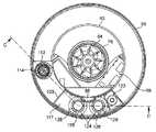
本体12は、ほぼ円筒形である。本体12は、ノズル14が装着される基部56を含む。基部56は、円筒形の外部外壁57を有し、この外壁は空気入口58を含む。この例では、空気入口58が、基部56の外壁57に形成された複数の開口を含む。基部56は、第1の空気流をノズル14を通じて第1の空気流路へ運ぶための第1の空気通路60と、第2の空気流をノズル14を通じて第2の空気流路へ運ぶための第2の空気通路62とを含む。 The
基部56の前部は、ファン組立体10のユーザインターフェイスを含むことができる。このユーザインターフェイスについては図9に概略的に示しており、以下でより詳細に説明する。基部56に形成された開口を通じて、ファン組立体10に電力を供給するための主電力ケーブル(図示せず)が延びる。 The front portion of the base 56 can include the user interface of the
第1の空気通路60は、基部56を通じて空気入口58からノズル14の第1の空気入口30へ延びる。一般に、第1の空気通路60は、基部56の管状上壁63によって定められる。ノズル14の管状基部28は、上壁63の開放上端に挿入される。上壁63は、第1の空気通路60を通じて、第1の空気流を発生させるための羽根車64の周囲に延びる。この実施形態では、羽根車64が混成流羽根車の形をしている。羽根車64は、この羽根車64を駆動するためのモータ66から外向きに延びる回転シャフトに接続される。この実施形態では、モータ66がDCブラシレスモータであり、このモータの速度は、ユーザによる速度の選択に応答して駆動回路68によって可変である。モータ66の最大速度は、5,000〜10,000rpmであることが好ましい。モータ66は、下部72に接続された上部70を含むモータバケット内に収容される。モータバケットの上部70は、湾曲した羽根を有する静止円盤の形のディフューザ74を含む。ディフューザ74は、ノズル14の第1の空気入口30の下方に位置する。 The
モータバケットは、ほぼ裁頭円錐形の羽根車ハウジング76内に位置してこれに装着される。さらに、羽根車ハウジング76は、上壁63から内向きに延びる環状支持体78上に装着される。羽根車ハウジング76の底部には、空気流を羽根車ハウジング76内へ導くための環状入口部材80が接続される。羽根車ハウジング76と環状支持体78の間には環状密封部材82が位置して、羽根車ハウジング76の外面の周囲を入口部材80に空気が通過するのを防ぐ。環状支持体78は、駆動回路68からモータ66へ電気ケーブルを導くためのガイド部分84を含むことが好ましい。 The motor bucket is located within and attached to a generally
第2の空気通路62は、第1の空気通路60からの空気を受け入れるように配置される。第2の空気通路62は、第1の空気通路60に隣接して位置する。第2の空気通路62は、ディフューザ74から放出された空気流の一部を受け入れるための、ディフューザ74から下流に位置する入口ポート86を含む。第2の空気通路62は、入口ポート86からの第2の空気流を受け入れるように配置された入口ダクト88によって定められる。図5及び図6を参照して分かるように、入口ダクト88は上壁63によって定められ、第1の空気通路60の一部に隣接して、この例では第1の空気通路60の前に位置する。第2の空気通路62は、入口ダクト88からの第2の空気流を受け入れ、この空気流をノズル14の第2の空気入口42へ運ぶように配置された出口ダクト90によってさらに定められる。第2の空気流は、入口ダクト88及び出口ダクト90を通じてほぼ逆方向に運ばれる。ノズル14の第2の外側ケーシング部分32の基部40は、出口ダクト90の開放上端に挿入される。 The
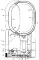
この例では、ファン組立体10が、第2の空気流がノズル14に入る前にこの第2の空気流の湿度を増加させるための加湿手段を含み、この手段は、ファン組立体10の本体12内に収容される。図4〜図6を参照して分かるように、この加湿手段は、本体12の基部56上に取り外し可能に装着できる水タンク100を含む。水タンク100は、基部56上に水タンク100が装着されたときに基部12の外観が円筒形になるように、本体12の基部56の外部外壁57と同じ半径の円筒形の外壁102を有する。水タンク100は、基部56の上壁63と同じ形状を有してこれを取り囲む環状内壁104を有する。外壁102及び内壁104は、水タンク100の上壁106及び下壁108とともに、水を蓄えるための環状容量を定める。従って、水タンク100は、羽根車64及びモータ66、すなわち第1の空気通路60の少なくとも一部及び第2の空気通路62の少なくとも一部を取り囲む。 In this example, the
水タンク100は、2〜4リットルの容量を有することが好ましい。水タンク100の上壁106は、ハンドル110を定めるように成形されて、ユーザが水タンク100を基部56から片手で持ち上げることができるようにされる。水タンク100の外壁102には窓111を設けて、基部ステーション56上に水タンク100が配置されたときに、ユーザが水タンク100内の水のレベルを確認できるようにする。 The
水タンク100の下壁108には、例えば、協働するネジ接続を通じて、放出口112が取り外し可能に接続される。この例では、基部56から水タンク110を取り外し、放出口112が上方へ突出するように水タンク110を反転させることにより、水タンク110が充填される。次に、水タンク100から放出口112をねじって外し、水タンク100から放出口112を外したときに露出される開口を通じて水タンク100内に水を導入する。水タンク100が充填されると、ユーザは、放出口112を水タンク100に再接続し、水タンク100を再び反転させて、水タンク100を基部56上に置き直す。放出口112内には、水タンク110を再反転させたときに、放出口112の水出口116を通る水の漏出を防ぐためのバネ仕掛け弁114が位置する。この弁114は、弁114のスカート部が放出口112の上面と係合する位置の方へ付勢されて、水タンク110から放出口112に水が入るのを防ぐ。 A
基部56は、水タンク100からの水を受け入れるための水容器118を定める内壁117を含む。この例では、水容器118が200mlの容量を有する。水タンク100が基部56上に位置するときには、上方へ延びる基部56のピン120が、放出口112内に突出する。このピン120は、弁114を上方に押して放出口112を開き、これにより水が重力によって水タンク100から水容器118内に流入できるようにする。この結果、ピン120の上面と実質的に同一平面上にあるレベルまで水容器118に水が満たされるようになる。水容器118内には、水容器118内の水のレベルを検出するための磁気レベルセンサ122が配置される。
基部56の内壁117は、水容器118に蓄えられた水を霧化するためのそれぞれの圧電変換器126の表面を各々が露出させるための開口124を含む。下壁117と変換器126の間には、変換器126から離れて熱を運ぶための金属ヒートシンク128が位置する。ヒートシンク128の一部は、このヒートシンク128から本体12の基部56の外面に形成された第2の開口の組を通じて熱が伝わるように、この開口に隣接して位置することができる。変換器126とヒートシンク128の間には、環状密封部材が不透水性シールを形成する。駆動回路68は、変換器126の超音波振動を作動させて、水容器118内の水を霧化させる。 The
水容器118内の水の最高レベルよりも上方には、入口ダクト88と出口ダクト90の開放底端部が各々位置し、これらのダクト88、89の間において、水容器118内に存在する水の水面上を第2の空気流が通過するようにする。出口ダクト90は、水タンク100によって定められる。 Above the highest level of water in the
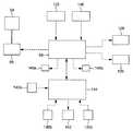
本体12のケーシング部分の側壁には、ファン組立体の動作を制御するためのユーザインターフェイスが位置する。図9に、このユーザインターフェイス及びファン組立体10のその他の電気構成要素を含む、ファン組立体10の制御システムを概略的に示す。この例では、ユーザインターフェイスが、複数のユーザ操作可能ボタン140a、140b及び140c、並びにディスプレイ142を含む。第1のボタン140aは、モータ66を作動及び停止させるために使用され、第2のボタン140bは、モータ66の速度、従って羽根車64の回転速度を設定するために使用される。第3のボタン140cは、部屋、オフィス又はその他の家庭内環境などの、ファン組立体10が存在する環境の所望の相対湿度レベルを設定するために使用される。例えば、第3のボタン140cを繰り返し作動させることにより、この所望の相対湿度レベルを20℃において30%〜80%の範囲内で選択することができる。ディスプレイ142は、現在選択されている相対湿度レベルを示す。 A user interface for controlling the operation of the fan assembly is located on the side wall of the casing portion of the
ユーザインターフェイスは、ボタンの1つが作動されたときに駆動回路68に制御信号を出力し、駆動回路68により出力された制御信号を受け取るユーザインターフェイス回路144をさらに含む。このユーザインターフェイスは、加湿装置の状態に応じて視覚的警告を与えるための1又はそれ以上のLEDを含むこともできる。例えば、駆動回路68がレベルセンサ122から受け取った信号によって水タンク100が空になったことが示された場合、このことを示す第1のLED146aを駆動回路68によって点灯させることができる。 The user interface further includes a
外部環境内の空気の相対湿度を検出し、この検出した相対湿度を示す信号を駆動回路68に供給するための湿度センサ148も設けられる。この例では、ファン組立体10内に引き込まれた空気流の相対湿度を検出するために、湿度センサ148を空気入口58のすぐ後方に配置することができる。ユーザインターフェイスは、湿度センサ148からの出力が、ファン組立体10に入る空気流の相対湿度がユーザにより設定された所望の相対湿度レベル以上であることを示す場合に駆動回路68によって点灯される第2のLED146bを含むことができる。 A
ファン組立体10を動作させるには、ユーザが第1のボタン140aを作動させ、これに応答して駆動回路68がモータ66を作動させて羽根車64を回転させる。羽根車64が回転すると、空気入口58を通じて本体12内に空気が引き込まれるようになる。空気流が、羽根車ハウジング76及びディフューザ74を通過する。ディフューザ74の下流において、ディフューザ74から放出された空気の一部が入口ポート86を通じて入口ダクト88に入り込むのに対し、ディフューザ74から放出された空気の残りは、上壁63によってノズル14の第1の空気入口30へ運ばれる。従って、羽根車64及びモータ66は、第1の空気通路60によってノズル14へ運ばれ第1の空気入口30を通じてノズル14に入り込む第1の空気流を発生させると考えることができる。 In order to operate the
この第1の空気流は、ノズル14の後側部分16の基部において第1の内部通路48に入る。この第1の内部通路48の基部において、空気流は、ノズル14のボア20の周囲を反対方向に通過する2つの空気ストリームに分かれる。この空気ストリームが第1の内部通路48を通過すると、空気がノズル14の口部50に入る。口部50内への空気流は、ノズル14のボア20の周囲で実質的に均一であることが好ましい。口部50は、この空気流をノズル14の第1の空気出口44の方へ導き、ここを通じて空気流がファン組立体10から放出される。 This first air stream enters the first
第1の空気出口44から放出された空気流は、外部環境からの、特に第1の空気出口44の周囲領域及びノズル14の後部周囲からの空気を同伴することにより第2の空気流を生じるようになる。この二次空気流の一部は、ノズル14のボア20を通過するのに対し、二次空気流の残りは、ノズル14の前方の第1の空気出口から放出された空気流に同伴される。 The air flow emitted from the
上述したように、羽根車64の回転とともに、入口ダクト88の入口ポート86を通じて第2の空気通路62に空気が入り込む。モータ66が作動すると同時に、駆動回路68が、好ましくは1〜2MHzの周波数f1で変換器126の振動を作動させて、水容器118内に存在する水を霧化する。これにより、水容器118内に存在する水の上に水飛沫が生じる。水容器118内の水が霧化されるにつれ、水容器118には水タンク100から水が絶えず補給され、水容器118内の水のレベルは実質的に一定を保つ一方で、水タンク100内の水のレベルは徐々に低下するようになる。 As described above, air enters the
羽根車66の回転とともに、第2の空気流が入口ダクト88を通過し、水容器118内に存在する水の上に直接放出されて、第2の空気流内に水飛沫が同伴するようになる。今や湿気を帯びたこの第2の空気流は、第2の空気通路62の出口ダクト90を通ってノズル14の第2の空気入口42まで上方に移動し、ノズル14の前側部分18内の第2の内部通路54に入る。 As the
第2の内部通路54の基部において、この第2の空気流は、ノズル14のボア20の周囲を反対方向に通過する2つの空気ストリームに分かれる。この空気ストリームが第2の内部通路54を通過すると、各空気ストリームは、ノズル14の前端の第1の空気出口44の前に位置する第2の空気出口52のそれぞれの一方から放出される。放出された第2の空気流は、ノズル14から第1の空気流が放出されることによって生じた空気流内でファン組立体10から離れて運ばれ、これによりファン組立体10から数メートルの距離で湿度の高い空気流が急速に体感できるようになる。 At the base of the second
湿度センサ148によって検出したファン組立体に入る空気流の相対湿度が、第3のボタン140cを使用してユーザにより選択された相対湿度レベルよりも20℃において1%高くなるまで、この湿り空気流がノズル14から放出される。その後、ノズル14からの湿り空気流の放出は、好ましくは変換器126の振動の周波数を周波数f2に低下させることにより(f1>f2≧0)、駆動回路68によって終了することができる。任意に、ノズル14から空気流が放出されないようにモータ66を停止することもできる。しかしながら、湿度センサ148がモータ66のすぐ近くに位置する場合は、モータ66を継続的に動作させて、湿度センサ148の局所環境における不適切な温度変化を避けることが好ましい。This humid airflow is detected until the relative humidity of the airflow entering the fan assembly detected by the
ファン組立体10からの湿り空気流の放出が終了したことを受けて、湿度センサ148により検出される相対湿度は低下し始める。湿度センサ148に近い環境の空気の相対湿度が、ユーザにより選択された相対湿度レベルを20℃において1%下回るまで低下すると、駆動回路68は、変換器126の振動を周波数f1で再始動する。モータ66が停止している場合、駆動回路68は、同時にモータ66を再始動する。上述したように、湿度センサ170によって検出される相対湿度が、ユーザにより選択された相対湿度レベルよりも20℃において1%高くなるまでノズル14から湿り空気流が放出される。The relative humidity detected by the
この変換器126(及び任意にモータ66)の、検出される湿度レベルをユーザにより選択されたレベル付近に維持するための作動シーケンスは、ボタン140aが再び作動されるまで、又は水容器118内の水のレベルが最低レベルまで低下したことを示す信号をレベルセンサ122から受け取るまで続く。ボタン140aが作動された場合、駆動回路68は、モータ66及び変換器126を停止してファン組立体10のスイッチを切る。 The activation sequence for this transducer 126 (and optionally the motor 66) to maintain the detected humidity level near the level selected by the user is either until the
本発明は、以下のような態様であっても良い。
[1]
ノズルと、
前記ノズルが装着された本体と、
を備えたファン組立体であって、
前記ノズルが、少なくとも1つの第1の空気入口と、少なくとも1つの第1の空気出口と、前記少なくとも1つの第1の空気入口から前記少なくとも1つの第1の空気出口へ空気を運ぶための第1の内部通路と、少なくとも1つの第2の空気入口と、少なくとも1つの第2の空気出口と、前記少なくとも1つの第2の空気入口から前記少なくとも1つの第2の空気出口へ空気を運ぶための第2の内部通路と有し、前記ノズルがボアを定め、該ボアの周囲を前記2つの内部通路が延び、前記ボアを通じて、前記2つの空気出口から放出された空気によってファン組立体の外部からの空気が引き込まれ、
前記本体が、前記第1の内部通路を通る第1の空気流及び前記第2の内部通路を通る第2の空気流を発生させるための流れ発生手段と、前記第1の空気流を前記少なくとも1つの第1の空気入口へ運ぶための第1の空気通路と、前記第2の空気流を前記少なくとも1つの第2の空気入口へ運ぶための、前記流れ発生手段から下流に前記第1の空気通路からの空気を受け入れるように配置された第2の空気通路とを含み、
前記第2の空気流の温度、湿度、組成及び電荷のうちの1つを変化させるための手段をさらに備える、
ことを特徴とするファン組立体。The following aspects may be sufficient as this invention.
[1]
A nozzle,
A main body to which the nozzle is mounted;
A fan assembly comprising:
The nozzle has at least one first air inlet, at least one first air outlet, and a first for carrying air from the at least one first air inlet to the at least one first air outlet. One internal passage, at least one second air inlet, at least one second air outlet, and for carrying air from the at least one second air inlet to the at least one second air outlet. A second internal passage, wherein the nozzle defines a bore, the two internal passages extend around the bore, and air is discharged from the two air outlets through the bore to the outside of the fan assembly. The air from
The body includes flow generating means for generating a first air flow through the first internal passage and a second air flow through the second internal passage; and A first air passage for carrying one first air inlet, and the first air passage downstream from the flow generating means for carrying the second air flow to the at least one second air inlet. A second air passage arranged to receive air from the air passage;
Means for changing one of temperature, humidity, composition and charge of the second air stream;
A fan assembly characterized by that.
[2]
前記第1の内部通路が、前記第2の内部通路から分離される、
ことを特徴とする上記[1]に記載のファン組立体。[2]
The first internal passage is separated from the second internal passage;
The fan assembly according to [1] above, wherein
[3]
前記第1の内部通路が、前記ノズルの前記ボアを取り囲む、
ことを特徴とする上記[1]又は上記[2]に記載のファン組立体。[3]
The first internal passage surrounds the bore of the nozzle;
The fan assembly according to [1] or [2] above, wherein
[4]
前記第2の内部通路が、前記ノズルの前記ボアを取り囲む、
ことを特徴とする上記[1]から上記[3]のいずれかに記載のファン組立体。[4]
The second internal passage surrounds the bore of the nozzle;
The fan assembly according to any one of [1] to [3] above, wherein
[5]
前記少なくとも1つの第1の空気出口が、前記ボアの少なくとも前部を通じて前記第1の空気流を放出するように配置される、
ことを特徴とする上記[1]から上記[4]のいずれかに記載のファン組立体。[5]
The at least one first air outlet is arranged to discharge the first air flow through at least the front of the bore;
The fan assembly according to any one of [1] to [4] above, wherein
[6]
前記少なくとも1つの第1の空気出口が、前記ボアの周囲に位置する複数の第1の空気出口を含む、
ことを特徴とする上記[1]から上記[5]のいずれかに記載のファン組立体。[6]
The at least one first air outlet comprises a plurality of first air outlets located around the bore;
The fan assembly according to any one of [1] to [5] above, wherein
[7]
前記少なくとも1つの第2の空気出口が、前記ノズルの前端に位置する、
ことを特徴とする上記[1]から上記[6]のいずれかに記載のファン組立体。[7]
The at least one second air outlet is located at a front end of the nozzle;
The fan assembly according to any one of [1] to [6] above, wherein
[8]
前記少なくとも1つの第2の空気出口が、前記ボアの周囲に位置する複数の空気出口を含む、
ことを特徴とする上記[7]に記載のファン組立体。[8]
The at least one second air outlet includes a plurality of air outlets located around the bore;
The fan assembly as set forth in [7] above, wherein
[9]
前記複数の空気出口の各々が、1又はそれ以上の開口を含む、
ことを特徴とする上記[1]から上記[8]のいずれかに記載のファン組立体。[9]
Each of the plurality of air outlets includes one or more openings;
The fan assembly according to any one of [1] to [8] above, wherein:
[10]
前記第2の空気流の温度、湿度、組成及び電荷のうちの1つを変化させるための前記手段が、前記本体内に位置する、
ことを特徴とする上記[1]から上記[9]のいずれかに記載のファン組立体。[10]
The means for changing one of temperature, humidity, composition and charge of the second air stream is located in the body;
The fan assembly according to any one of [1] to [9] above, wherein:
[11]
前記第2の空気流の温度、湿度、組成及び電荷のうちの1つを変化させるための前記手段が、少なくとも部分的に前記第2の空気通路内に位置する、
ことを特徴とする上記[1]から上記[10]のいずれかに記載のファン組立体。[11]
The means for changing one of temperature, humidity, composition and charge of the second air stream is located at least partially within the second air passage;
The fan assembly according to any one of [1] to [10] above, wherein
[12]
前記第2の空気流の温度、湿度、組成及び電荷のうちの1つを変化させるための前記手段が、前記第2の空気流を加湿するように構成される、
ことを特徴とする上記[1]から上記[11]のいずれかに記載のファン組立体。[12]
The means for changing one of temperature, humidity, composition and charge of the second air stream is configured to humidify the second air stream;
The fan assembly according to any one of [1] to [11] above, wherein
[13]
前記第2の空気流の温度、湿度、組成及び電荷のうちの1つを変化させるための前記手段が、水タンクを含む、
ことを特徴とする上記[1]から上記[12]のいずれかに記載のファン組立体。[13]
The means for changing one of temperature, humidity, composition and charge of the second air stream comprises a water tank;
The fan assembly according to any one of [1] to [12] above, wherein
[14]
前記本体が、前記本体に入る空気が通過する空気入口を有する基部を含み、前記水タンクが前記基部上に装着される、
ことを特徴とする上記[13]に記載のファン組立体。[14]
The body includes a base having an air inlet through which air entering the body passes, and the water tank is mounted on the base;
The fan assembly as set forth in [13] above, wherein
[15]
前記基部及び前記水タンクの各々が円筒形の外面を有し、前記基部及び前記水タンクの前記外面が、実質的に同じ半径を有する、
ことを特徴とする上記[14]に記載のファン組立体。[15]
Each of the base and the water tank has a cylindrical outer surface, and the outer surface of the base and the water tank have substantially the same radius,
The fan assembly as set forth in [14] above, wherein
[16]
前記第2の空気流の温度、湿度、組成及び電荷のうちの1つを変化させるための前記手段が、前記水タンクからの水を受け入れるための容器と、該容器に蓄えられた水を霧化するための変換器とを含み、前記第2の空気通路が、前記容器の少なくとも一部の上に前記第2の空気流を運ぶように配置される、
ことを特徴とする上記[13]から上記[15]のいずれかに記載のファン組立体。[16]
The means for changing one of the temperature, humidity, composition and charge of the second air stream comprises a container for receiving water from the water tank and mist of water stored in the container; The second air passage is arranged to carry the second air stream over at least a portion of the container,
The fan assembly according to any one of [13] to [15] above, wherein
10 ファン組立体
12 本体
14 ノズル
16 後側部分
18 前側部分
22 外側ケーシング部分
24 内側ケーシング部分
32 前側ケーシング部分
34 後側ケーシング部分
26 後部
28 管状基部
30 第1の空気入口
40 管状基部
42 第2の空気入口
44 第1の空気出口
48 第1の内部通路
52 第2の空気出口
54 第2の内部通路
56 基部
57 外壁
58 空気入口
60 第1の空気通路
62 第2の空気通路
63 上壁
64 羽根車
66 モータ
70 上部
72 下部
74 ディフューザ
76 羽根車ハウジング
78 環状支持体
80 環状入口部材
82 環状密封部材
84 ガイド部分
86 入口ポート
88 入口ダクト
90 出口ダクト
100 水タンク
102 外壁
104 内壁
106 上壁
108 下壁
110 ハンドル
111 窓
117 内壁
118 水容器
128 ヒートシンク
X 軸10
Claims (7)
Translated fromJapanese前記ノズルが装着された本体と、
を備えた加湿装置であって、
前記ノズルが、少なくとも1つの第1の空気入口と、少なくとも1つの第1の空気出口と、前記少なくとも1つの第1の空気入口から前記少なくとも1つの第1の空気出口へ空気を運ぶための第1の内部通路と、少なくとも1つの第2の空気入口と、少なくとも1つの第2の空気出口と、前記少なくとも1つの第2の空気入口から前記少なくとも1つの第2の空気出口へ空気を運ぶための第2の内部通路と有し、前記ノズルがボアを定め、該ボアを通じて、前記2つの空気出口から放出された空気によって加湿装置の外部からの空気が引き込まれ、
前記本体が、基部と、該基部上に装着される水タンクとを有し、前記基部が、前記第1の内部通路を通る第1の空気流及び前記第2の内部通路を通る第2の空気流を発生させるための流れ発生手段と、前記水タンクからの水を受け入れるための容器と、該容器に蓄えられた水を霧化するための変換器と、前記第1の空気流を前記少なくとも1つの第1の空気入口へ運ぶための第1の空気通路と、前記第2の空気流を前記容器の上に且つ前記少なくとも1つの第2の空気入口へ運ぶための第2の空気通路とを含む、
ことを特徴とする加湿装置。A nozzle,
A main body to which the nozzle is mounted;
A humidifying device comprising:
The nozzle has at least one first air inlet, at least one first air outlet, and a first for carrying air from the at least one first air inlet to the at least one first air outlet. One internal passage, at least one second air inlet, at least one second air outlet, and for carrying air from the at least one second air inlet to the at least one second air outlet. And the nozzle defines a bore through which air from the outside of the humidifier is drawn by the air discharged from the two air outlets,
The main body has a base and a water tank mounted on the base, and the base has a first air flow through the first internal passage and a second through the second internal passage. A flow generating means for generating an air flow, a container for receiving water from the water tank, a converter for atomizing the water stored in the container, and the first air flow A first air passage for carrying to at least one first air inlet and a second air passage for carrying said second air stream over said container and to said at least one second air inlet Including
A humidifier characterized by that.
ことを特徴とする請求項1に記載の加湿装置。The first internal passage is separated from the second internal passage;
The humidifying device according to claim 1.
ことを特徴とする請求項1又は請求項2に記載の加湿装置。The first internal passage surrounds the bore of the nozzle;
The humidifying device according to claim 1 or 2, characterized by the above.
ことを特徴とする請求項1から請求項3のいずれかに記載の加湿装置。The second internal passage surrounds the bore of the nozzle;
The humidifying device according to any one of claims 1 to 3, wherein the humidifying device is provided.
ことを特徴とする請求項1から請求項4のいずれかに記載の加湿装置。The at least one first air outlet comprises a plurality of first air outlets located around the bore;
The humidifying device according to any one of claims 1 to 4, wherein the humidifying device is provided.
ことを特徴とする請求項1から請求項5のいずれかに記載の加湿装置。The at least one second air outlet includes a plurality of air outlets located around the bore;
The humidifying device according to any one of claims 1 to 5, wherein
ことを特徴とする請求項1から請求項6のいずれかに記載の加湿装置。Each of the base and the water tank has a cylindrical outer surface, and the outer surface of the base and the water tank have substantially the same radius,
The humidifying device according to any one of claims 1 to 6, wherein:
Applications Claiming Priority (6)
| Application Number | Priority Date | Filing Date | Title |
|---|---|---|---|
| GB1112911.1 | 2011-07-27 | ||
| GB201112911AGB2493506B (en) | 2011-07-27 | 2011-07-27 | A fan assembly |
| GB1203888.1 | 2012-03-06 | ||
| GB201203887AGB2493231B (en) | 2011-07-27 | 2012-03-06 | A fan assembly |
| GB1203887.3 | 2012-03-06 | ||
| GB201203888AGB2493232B (en) | 2011-07-27 | 2012-03-06 | Humidifying apparatus |
Related Parent Applications (1)
| Application Number | Title | Priority Date | Filing Date |
|---|---|---|---|
| JP2012167517ADivisionJP5546592B2 (en) | 2011-07-27 | 2012-07-27 | Fan assembly |
Publications (2)
| Publication Number | Publication Date |
|---|---|
| JP2014156862A JP2014156862A (en) | 2014-08-28 |
| JP5717898B2true JP5717898B2 (en) | 2015-05-13 |
Family
ID=44676250
Family Applications (5)
| Application Number | Title | Priority Date | Filing Date |
|---|---|---|---|
| JP2012167517AExpired - Fee RelatedJP5546592B2 (en) | 2011-07-27 | 2012-07-27 | Fan assembly |
| JP2012167516AExpired - Fee RelatedJP5564080B2 (en) | 2011-07-27 | 2012-07-27 | Fan assembly |
| JP2014078888AActiveJP5717898B2 (en) | 2011-07-27 | 2014-04-07 | Fan assembly |
| JP2014122190AExpired - Fee RelatedJP6084949B2 (en) | 2011-07-27 | 2014-06-13 | Fan assembly |
| JP2016077486AAbandonedJP2016153721A (en) | 2011-07-27 | 2016-04-07 | Fan assembly |
Family Applications Before (2)
| Application Number | Title | Priority Date | Filing Date |
|---|---|---|---|
| JP2012167517AExpired - Fee RelatedJP5546592B2 (en) | 2011-07-27 | 2012-07-27 | Fan assembly |
| JP2012167516AExpired - Fee RelatedJP5564080B2 (en) | 2011-07-27 | 2012-07-27 | Fan assembly |
Family Applications After (2)
| Application Number | Title | Priority Date | Filing Date |
|---|---|---|---|
| JP2014122190AExpired - Fee RelatedJP6084949B2 (en) | 2011-07-27 | 2014-06-13 | Fan assembly |
| JP2016077486AAbandonedJP2016153721A (en) | 2011-07-27 | 2016-04-07 | Fan assembly |
Country Status (13)
| Country | Link |
|---|---|
| US (4) | US9291361B2 (en) |
| EP (3) | EP2737258B1 (en) |
| JP (5) | JP5546592B2 (en) |
| KR (3) | KR101570184B1 (en) |
| CN (8) | CN202833049U (en) |
| AU (3) | AU2012288596B2 (en) |
| BR (2) | BR112014001290A2 (en) |
| CA (2) | CA2842867C (en) |
| GB (5) | GB2493506B (en) |
| MY (4) | MY184973A (en) |
| RU (4) | RU2580781C2 (en) |
| SG (1) | SG10201406842QA (en) |
| WO (2) | WO2013014418A1 (en) |
Families Citing this family (113)
| Publication number | Priority date | Publication date | Assignee | Title |
|---|---|---|---|---|
| GB0814835D0 (en)* | 2007-09-04 | 2008-09-17 | Dyson Technology Ltd | A Fan |
| CN202056982U (en) | 2009-03-04 | 2011-11-30 | 戴森技术有限公司 | Humidifying device |
| GB2468325A (en)* | 2009-03-04 | 2010-09-08 | Dyson Technology Ltd | Height adjustable fan with nozzle |
| GB2468312A (en) | 2009-03-04 | 2010-09-08 | Dyson Technology Ltd | Fan assembly |
| PL2276933T3 (en) | 2009-03-04 | 2011-10-31 | Dyson Technology Ltd | A fan |
| GB2468323A (en)* | 2009-03-04 | 2010-09-08 | Dyson Technology Ltd | Fan assembly |
| JP5336890B2 (en)* | 2009-03-10 | 2013-11-06 | キヤノン株式会社 | Measuring apparatus, exposure apparatus, and device manufacturing method |
| GB0919473D0 (en) | 2009-11-06 | 2009-12-23 | Dyson Technology Ltd | A fan |
| SG186071A1 (en) | 2010-05-27 | 2013-01-30 | Dyson Technology Ltd | Device for blowing air by means of narrow slit nozzle assembly |
| GB2482547A (en) | 2010-08-06 | 2012-02-08 | Dyson Technology Ltd | A fan assembly with a heater |
| GB2482548A (en) | 2010-08-06 | 2012-02-08 | Dyson Technology Ltd | A fan assembly with a heater |
| JP5588565B2 (en) | 2010-10-13 | 2014-09-10 | ダイソン テクノロジー リミテッド | Blower assembly |
| EP2630373B1 (en) | 2010-10-18 | 2016-12-28 | Dyson Technology Limited | A fan assembly |
| GB2484670B (en) | 2010-10-18 | 2018-04-25 | Dyson Technology Ltd | A fan assembly |
| JP5778293B2 (en) | 2010-11-02 | 2015-09-16 | ダイソン テクノロジー リミテッド | Blower assembly |
| BR112014001474A2 (en) | 2011-07-27 | 2017-02-21 | Dyson Technology Ltd | fan assembly |
| GB2493506B (en) | 2011-07-27 | 2013-09-11 | Dyson Technology Ltd | A fan assembly |
| GB201119500D0 (en) | 2011-11-11 | 2011-12-21 | Dyson Technology Ltd | A fan assembly |
| GB2496877B (en) | 2011-11-24 | 2014-05-07 | Dyson Technology Ltd | A fan assembly |
| GB2499044B (en) | 2012-02-06 | 2014-03-19 | Dyson Technology Ltd | A fan |
| GB2499042A (en) | 2012-02-06 | 2013-08-07 | Dyson Technology Ltd | A nozzle for a fan assembly |
| GB2499041A (en) | 2012-02-06 | 2013-08-07 | Dyson Technology Ltd | Bladeless fan including an ionizer |
| GB2500017B (en) | 2012-03-06 | 2015-07-29 | Dyson Technology Ltd | A Humidifying Apparatus |
| GB2500012B (en) | 2012-03-06 | 2016-07-06 | Dyson Technology Ltd | A Humidifying Apparatus |
| GB2500011B (en) | 2012-03-06 | 2016-07-06 | Dyson Technology Ltd | A Humidifying Apparatus |
| RU2606194C2 (en) | 2012-03-06 | 2017-01-10 | Дайсон Текнолоджи Лимитед | Fan unit |
| GB2512192B (en) | 2012-03-06 | 2015-08-05 | Dyson Technology Ltd | A Humidifying Apparatus |
| GB2500010B (en)* | 2012-03-06 | 2016-08-24 | Dyson Technology Ltd | A humidifying apparatus |
| GB2500903B (en) | 2012-04-04 | 2015-06-24 | Dyson Technology Ltd | Heating apparatus |
| WO2013154000A1 (en)* | 2012-04-09 | 2013-10-17 | シャープ株式会社 | Air blowing device |
| GB2501301B (en) | 2012-04-19 | 2016-02-03 | Dyson Technology Ltd | A fan assembly |
| US20130320574A1 (en)* | 2012-05-18 | 2013-12-05 | The Yankee Candle Company, Inc. | Aerodynamic formula dispersing apparatus |
| AU350181S (en) | 2013-01-18 | 2013-08-15 | Dyson Technology Ltd | Humidifier or fan |
| AU350140S (en) | 2013-01-18 | 2013-08-13 | Dyson Technology Ltd | Humidifier or fan |
| BR302013003358S1 (en) | 2013-01-18 | 2014-11-25 | Dyson Technology Ltd | CONFIGURATION APPLIED ON HUMIDIFIER |
| AU350179S (en) | 2013-01-18 | 2013-08-15 | Dyson Technology Ltd | Humidifier or fan |
| GB2510196B (en)* | 2013-01-29 | 2016-07-27 | Dyson Technology Ltd | A fan assembly |
| SG11201505665RA (en) | 2013-01-29 | 2015-08-28 | Dyson Technology Ltd | A fan assembly |
| GB2510195B (en) | 2013-01-29 | 2016-04-27 | Dyson Technology Ltd | A fan assembly |
| CN103982404A (en)* | 2013-02-07 | 2014-08-13 | 任文华 | Fan |
| CA152655S (en) | 2013-03-07 | 2014-05-20 | Dyson Technology Ltd | Fan |
| CA152657S (en) | 2013-03-07 | 2014-05-20 | Dyson Technology Ltd | Fan |
| BR302013004394S1 (en) | 2013-03-07 | 2014-12-02 | Dyson Technology Ltd | CONFIGURATION APPLIED TO FAN |
| CA152658S (en) | 2013-03-07 | 2014-05-20 | Dyson Technology Ltd | Fan |
| USD729372S1 (en) | 2013-03-07 | 2015-05-12 | Dyson Technology Limited | Fan |
| CA152656S (en) | 2013-03-07 | 2014-05-20 | Dyson Technology Ltd | Fan |
| GB2536767B (en)* | 2013-03-11 | 2017-11-15 | Dyson Technology Ltd | A fan assembly nozzle with control port |
| CA154722S (en) | 2013-08-01 | 2015-02-16 | Dyson Technology Ltd | Fan |
| CA154723S (en) | 2013-08-01 | 2015-02-16 | Dyson Technology Ltd | Fan |
| TWD172707S (en) | 2013-08-01 | 2015-12-21 | 戴森科技有限公司 | A fan |
| GB2518638B (en) | 2013-09-26 | 2016-10-12 | Dyson Technology Ltd | Humidifying apparatus |
| GB2518656B (en)* | 2013-09-27 | 2016-04-13 | Dyson Technology Ltd | Hand held appliance |
| KR101614099B1 (en)* | 2014-01-02 | 2016-04-21 | 송재하 | Electric fan having cold wind function |
| KR101423288B1 (en)* | 2014-05-27 | 2014-07-24 | 주식회사 이담테크 | Apparatus for humid air injection |
| CN104747508A (en)* | 2014-07-21 | 2015-07-01 | 周鸿钧 | Humidifying bladeless fan |
| GB2528709B (en) | 2014-07-29 | 2017-02-08 | Dyson Technology Ltd | Humidifying apparatus |
| GB2528708B (en) | 2014-07-29 | 2016-06-29 | Dyson Technology Ltd | A fan assembly |
| GB2528704A (en) | 2014-07-29 | 2016-02-03 | Dyson Technology Ltd | Humidifying apparatus |
| TWD173929S (en)* | 2015-01-30 | 2016-02-21 | 戴森科技有限公司 | A fan |
| TWD173928S (en)* | 2015-01-30 | 2016-02-21 | 戴森科技有限公司 | A fan |
| TWD173931S (en)* | 2015-01-30 | 2016-02-21 | 戴森科技有限公司 | A fan |
| TWD179707S (en)* | 2015-01-30 | 2016-11-21 | 戴森科技有限公司 | A fan |
| TWD173930S (en)* | 2015-01-30 | 2016-02-21 | 戴森科技有限公司 | A fan |
| TWD173932S (en)* | 2015-01-30 | 2016-02-21 | 戴森科技有限公司 | A fan |
| CN104696293B (en)* | 2015-03-02 | 2016-08-24 | 周午贤 | Focus on variable bladeless fan |
| USD790052S1 (en)* | 2015-04-20 | 2017-06-20 | Sung Woo Ha | Electric fan |
| CN104819132B (en)* | 2015-05-27 | 2017-08-01 | 广东美的环境电器制造有限公司 | Base for bladeless fan and bladeless fan |
| GB2540165B (en)* | 2015-07-07 | 2019-09-11 | Dyson Technology Ltd | Humidifying apparatus |
| GB2540166B (en)* | 2015-07-07 | 2019-06-12 | Dyson Technology Ltd | Humidifying apparatus |
| US9726389B2 (en)* | 2015-07-24 | 2017-08-08 | Ledatron Company Limited | Personal evaporative cooling apparatus |
| KR101592150B1 (en) | 2015-10-07 | 2016-02-04 | 이영희 | Air amplifying fan |
| USD804007S1 (en)* | 2015-11-25 | 2017-11-28 | Vornado Air Llc | Air circulator |
| US10837659B2 (en) | 2015-12-02 | 2020-11-17 | Coway Co., Ltd. | Air purifier |
| CN105509173A (en)* | 2016-01-13 | 2016-04-20 | 成都佳美嘉科技有限公司 | Novel intelligent air purifier |
| USD789506S1 (en) | 2016-02-24 | 2017-06-13 | Georgia-Pacific Consumer Products Lp | Air freshener |
| USD788285S1 (en)* | 2016-02-25 | 2017-05-30 | Georgia-Pacific Consumer Products Lp | Air freshener |
| CN105715520A (en)* | 2016-04-16 | 2016-06-29 | 任文华 | Fan |
| US12000621B2 (en)* | 2016-12-07 | 2024-06-04 | Coway Co., Ltd. | Wind-direction adjustable air purifier |
| CN108397273B (en)* | 2017-02-06 | 2022-04-29 | 福特环球技术公司 | Cooling fan for engine cooling system |
| DE102017102436A1 (en)* | 2017-02-08 | 2018-08-09 | Abb Schweiz Ag | Drying transformer with air cooling |
| US10729293B2 (en) | 2017-02-15 | 2020-08-04 | The Toro Company | Debris blower incorporating flow ejector |
| US10807726B2 (en)* | 2017-03-20 | 2020-10-20 | Goodrich Corporation | Evacuation assembly aspirator |
| CN106813346A (en)* | 2017-04-10 | 2017-06-09 | 中山市大毅电器科技有限公司 | On add water humidifier |
| US11384956B2 (en) | 2017-05-22 | 2022-07-12 | Sharkninja Operating Llc | Modular fan assembly with articulating nozzle |
| US10612984B2 (en)* | 2017-09-28 | 2020-04-07 | Rosemount Aerospace Inc. | Sensor aspiration utilizing hoop airflow induction |
| CN107687439B (en)* | 2017-09-30 | 2018-08-07 | 程凌军 | A kind of electric fan with safety basement |
| USD888219S1 (en)* | 2017-12-11 | 2020-06-23 | Dyson Technology Limited | Fan |
| USD895781S1 (en)* | 2017-12-11 | 2020-09-08 | Dyson Technology Limited | Fan |
| USD888928S1 (en)* | 2017-12-11 | 2020-06-30 | Dyson Technology Limited | Fan |
| USD888220S1 (en)* | 2017-12-11 | 2020-06-23 | Dyson Technology Limited | Fan |
| USD888927S1 (en)* | 2017-12-11 | 2020-06-30 | Dyson Technology Limited | Fan |
| USD888929S1 (en)* | 2017-12-11 | 2020-06-30 | Dyson Technology Limited | Fan |
| CN208011975U (en)* | 2018-03-05 | 2018-10-26 | 深圳前海帕拓逊网络技术有限公司 | A kind of atomizing humidifier |
| WO2019191237A1 (en)* | 2018-03-29 | 2019-10-03 | Walmart Apollo, Llc | Aerial vehicle turbine system |
| US10926210B2 (en) | 2018-04-04 | 2021-02-23 | ACCO Brands Corporation | Air purifier with dual exit paths |
| CN108758936A (en)* | 2018-04-16 | 2018-11-06 | 丁燕华 | A kind of multi-functional humidification device |
| USD913467S1 (en) | 2018-06-12 | 2021-03-16 | ACCO Brands Corporation | Air purifier |
| CN110594886B (en)* | 2018-06-12 | 2021-06-29 | 成都星图时代科技有限公司 | Air purification and humidification equipment and air humidification device thereof |
| CN109114801A (en)* | 2018-08-03 | 2019-01-01 | 四川万豪电子科技有限公司 | Entertaining electricity fireplace with humidification function |
| CN109057666B (en)* | 2018-08-14 | 2021-05-11 | 广东工业大学 | Exhaust fan |
| GB201900016D0 (en)* | 2019-01-02 | 2019-02-13 | Dyson Technology Ltd | Air treatment apparatus |
| GB201900022D0 (en)* | 2019-01-02 | 2019-02-13 | Dyson Technology Ltd | Air treatment apparatus |
| GB201900025D0 (en)* | 2019-01-02 | 2019-02-13 | Dyson Technology Ltd | A fan assembly |
| CN110778535B (en)* | 2019-10-31 | 2023-08-25 | 应辉 | Bladeless fan for purifying air and filter screen replacement method thereof |
| WO2021226749A1 (en)* | 2020-05-09 | 2021-11-18 | Sz Zuvi Technology Co., Ltd. | Apparatuses and methods for drying an object |
| USD965129S1 (en)* | 2020-12-17 | 2022-09-27 | Shenzhen OriginX Technology Co., LTD. | Leafless air purifier |
| JP1695844S (en)* | 2021-02-03 | 2021-09-27 | Rack for automatic guided vehicle | |
| JP1697628S (en)* | 2021-02-03 | 2021-10-18 | Automated guided vehicle | |
| JP1695782S (en)* | 2021-02-03 | 2021-09-27 | Rack for automatic guided vehicle | |
| USD1057918S1 (en) | 2021-06-23 | 2025-01-14 | Sharkninja Operating Llc | Air purifier |
| USD1079922S1 (en) | 2022-11-30 | 2025-06-17 | Vornado Air, Llc | Tower fan |
| US20250213029A1 (en) | 2023-01-19 | 2025-07-03 | Sharkninja Operating Llc | Hair care appliance with powered attachment |
| US20240245190A1 (en) | 2023-01-19 | 2024-07-25 | Sharkninja Operating Llc | Identification of hair care appliance attachments |
Family Cites Families (489)
| Publication number | Priority date | Publication date | Assignee | Title |
|---|---|---|---|---|
| GB593828A (en) | 1945-06-14 | 1947-10-27 | Dorothy Barker | Improvements in or relating to propeller fans |
| US284962A (en) | 1883-09-11 | William huston | ||
| GB601222A (en) | 1944-10-04 | 1948-04-30 | Berkeley & Young Ltd | Improvements in, or relating to, electric fans |
| US3185448A (en) | 1963-06-03 | 1965-05-25 | Urquhart S 1926 Ltd | Apparatus for mixing fluids |
| US1357261A (en) | 1918-10-02 | 1920-11-02 | Ladimir H Svoboda | Fan |
| US1767060A (en) | 1928-10-04 | 1930-06-24 | W H Addington | Electric motor-driven desk fan |
| US2014185A (en) | 1930-06-25 | 1935-09-10 | Martin Brothers Electric Compa | Drier |
| GB383498A (en) | 1931-03-03 | 1932-11-17 | Spontan Ab | Improvements in or relating to fans, ventilators, or the like |
| US1896869A (en) | 1931-07-18 | 1933-02-07 | Master Electric Co | Electric fan |
| US2035733A (en) | 1935-06-10 | 1936-03-31 | Marathon Electric Mfg | Fan motor mounting |
| US2071266A (en) | 1935-10-31 | 1937-02-16 | Continental Can Co | Lock top metal container |
| US2210458A (en) | 1936-11-16 | 1940-08-06 | Lester S Keilholtz | Method of and apparatus for air conditioning |
| US2115883A (en) | 1937-04-21 | 1938-05-03 | Sher Samuel | Lamp |
| US2258961A (en) | 1939-07-26 | 1941-10-14 | Prat Daniel Corp | Ejector draft control |
| US2336295A (en) | 1940-09-25 | 1943-12-07 | Reimuller Caryl | Air diverter |
| US2363839A (en) | 1941-02-05 | 1944-11-28 | Demuth Charles | Unit type air conditioning register |
| US2295502A (en) | 1941-05-20 | 1942-09-08 | Lamb Edward | Heater |
| GB641622A (en) | 1942-05-06 | 1950-08-16 | Fernan Oscar Conill | Improvements in or relating to hair drying |
| US2433795A (en) | 1945-08-18 | 1947-12-30 | Westinghouse Electric Corp | Fan |
| US2476002A (en) | 1946-01-12 | 1949-07-12 | Edward A Stalker | Rotating wing |
| US2547448A (en) | 1946-02-20 | 1951-04-03 | Demuth Charles | Hot-air space heater |
| US2473325A (en) | 1946-09-19 | 1949-06-14 | E A Lab Inc | Combined electric fan and air heating means |
| US2544379A (en) | 1946-11-15 | 1951-03-06 | Oscar J Davenport | Ventilating apparatus |
| US2488467A (en)* | 1947-09-12 | 1949-11-15 | Lisio Salvatore De | Motor-driven fan |
| GB633273A (en) | 1948-02-12 | 1949-12-12 | Albert Richard Ponting | Improvements in or relating to air circulating apparatus |
| US2510132A (en) | 1948-05-27 | 1950-06-06 | Morrison Hackley | Oscillating fan |
| GB661747A (en) | 1948-12-18 | 1951-11-28 | British Thomson Houston Co Ltd | Improvements in and relating to oscillating fans |
| US2620127A (en) | 1950-02-28 | 1952-12-02 | Westinghouse Electric Corp | Air translating apparatus |
| US2583374A (en) | 1950-10-18 | 1952-01-22 | Hydraulic Supply Mfg Company | Exhaust fan |
| FR1033034A (en) | 1951-02-23 | 1953-07-07 | Articulated stabilizer support for fan with flexible propellers and variable speeds | |
| US2711682A (en)* | 1951-08-04 | 1955-06-28 | Ilg Electric Ventilating Co | Power roof ventilator |
| US2813673A (en) | 1953-07-09 | 1957-11-19 | Gilbert Co A C | Tiltable oscillating fan |
| US2838229A (en) | 1953-10-30 | 1958-06-10 | Roland J Belanger | Electric fan |
| US2765977A (en) | 1954-10-13 | 1956-10-09 | Morrison Hackley | Electric ventilating fans |
| FR1119439A (en) | 1955-02-18 | 1956-06-20 | Enhancements to portable and wall fans | |
| US2830779A (en) | 1955-02-21 | 1958-04-15 | Lau Blower Co | Fan stand |
| NL110393C (en) | 1955-11-29 | 1965-01-15 | Bertin & Cie | |
| CH346643A (en) | 1955-12-06 | 1960-05-31 | K Tateishi Arthur | Electric fan |
| US2808198A (en) | 1956-04-30 | 1957-10-01 | Morrison Hackley | Oscillating fans |
| GB863124A (en) | 1956-09-13 | 1961-03-15 | Sebac Nouvelle Sa | New arrangement for putting gases into movement |
| BE560119A (en) | 1956-09-13 | |||
| US2922570A (en) | 1957-12-04 | 1960-01-26 | Burris R Allen | Automatic booster fan and ventilating shield |
| US3004403A (en) | 1960-07-21 | 1961-10-17 | Francis L Laporte | Refrigerated space humidification |
| DE1291090B (en) | 1963-01-23 | 1969-03-20 | Schmidt Geb Halm Anneliese | Device for generating an air flow |
| DE1457461A1 (en) | 1963-10-01 | 1969-02-20 | Siemens Elektrogeraete Gmbh | Suitcase-shaped hair dryer |
| FR1387334A (en) | 1963-12-21 | 1965-01-29 | Hair dryer capable of blowing hot and cold air separately | |
| US3270655A (en) | 1964-03-25 | 1966-09-06 | Howard P Guirl | Air curtain door seal |
| US3518776A (en) | 1967-06-03 | 1970-07-07 | Bremshey & Co | Blower,particularly for hair-drying,laundry-drying or the like |
| US3487555A (en) | 1968-01-15 | 1970-01-06 | Hoover Co | Portable hair dryer |
| US3495343A (en) | 1968-02-20 | 1970-02-17 | Rayette Faberge | Apparatus for applying air and vapor to the face and hair |
| JPS467230Y1 (en) | 1968-06-28 | 1971-03-15 | ||
| US3503138A (en) | 1969-05-19 | 1970-03-31 | Oster Mfg Co John | Hair dryer |
| GB1278606A (en) | 1969-09-02 | 1972-06-21 | Oberlind Veb Elektroinstall | Improvements in or relating to transverse flow fans |
| US3645007A (en) | 1970-01-14 | 1972-02-29 | Sunbeam Corp | Hair dryer and facial sauna |
| JPS4721718Y1 (en) | 1970-04-20 | 1972-07-17 | ||
| DE2944027A1 (en) | 1970-07-22 | 1981-05-07 | Erevanskyj politechničeskyj institut imeni Karla Marksa, Erewan | EJECTOR ROOM AIR CONDITIONER OF THE CENTRAL AIR CONDITIONING |
| GB1319793A (en) | 1970-11-19 | 1973-06-06 | ||
| US3724092A (en) | 1971-07-12 | 1973-04-03 | Westinghouse Electric Corp | Portable hair dryer |
| GB1403188A (en) | 1971-10-22 | 1975-08-28 | Olin Energy Systems Ltd | Fluid flow inducing apparatus |
| JPS517258Y2 (en) | 1971-11-15 | 1976-02-27 | ||
| US3743186A (en) | 1972-03-14 | 1973-07-03 | Src Lab | Air gun |
| JPS5515226Y2 (en) | 1972-07-20 | 1980-04-08 | ||
| JPS5134785B2 (en)* | 1972-08-31 | 1976-09-28 | ||
| US3885891A (en) | 1972-11-30 | 1975-05-27 | Rockwell International Corp | Compound ejector |
| US3795367A (en) | 1973-04-05 | 1974-03-05 | Src Lab | Fluid device using coanda effect |
| US3872916A (en) | 1973-04-05 | 1975-03-25 | Int Harvester Co | Fan shroud exit structure |
| JPS49150403U (en) | 1973-04-23 | 1974-12-26 | ||
| US4037991A (en) | 1973-07-26 | 1977-07-26 | The Plessey Company Limited | Fluid-flow assisting devices |
| US3875745A (en) | 1973-09-10 | 1975-04-08 | Wagner Minning Equipment Inc | Venturi exhaust cooler |
| GB1434226A (en) | 1973-11-02 | 1976-05-05 | Roberts S A | Pumps |
| US3943329A (en) | 1974-05-17 | 1976-03-09 | Clairol Incorporated | Hair dryer with safety guard air outlet nozzle |
| CA1055344A (en) | 1974-05-17 | 1979-05-29 | International Harvester Company | Heat transfer system employing a coanda effect producing fan shroud exit |
| US4180130A (en) | 1974-05-22 | 1979-12-25 | International Harvester Company | Heat exchange apparatus including a toroidal-type radiator |
| US4184541A (en) | 1974-05-22 | 1980-01-22 | International Harvester Company | Heat exchange apparatus including a toroidal-type radiator |
| GB1501473A (en) | 1974-06-11 | 1978-02-15 | Charbonnages De France | Fans |
| GB1593391A (en) | 1977-01-28 | 1981-07-15 | British Petroleum Co | Flare |
| GB1495013A (en) | 1974-06-25 | 1977-12-14 | British Petroleum Co | Coanda unit |
| JPS517258A (en) | 1974-07-11 | 1976-01-21 | Tsudakoma Ind Co Ltd | YOKOITO CHORYUSOCHI |
| DE2451557C2 (en)* | 1974-10-30 | 1984-09-06 | Arnold Dipl.-Ing. 8904 Friedberg Scheel | Device for ventilating a occupied zone in a room |
| US4061188A (en) | 1975-01-24 | 1977-12-06 | International Harvester Company | Fan shroud structure |
| US4136735A (en) | 1975-01-24 | 1979-01-30 | International Harvester Company | Heat exchange apparatus including a toroidal-type radiator |
| RO62593A (en) | 1975-02-12 | 1977-12-15 | Inst Pentru Creatie Stintific | GASLIFT DEVICE |
| US4173995A (en) | 1975-02-24 | 1979-11-13 | International Harvester Company | Recirculation barrier for a heat transfer system |
| US4332529A (en) | 1975-08-11 | 1982-06-01 | Morton Alperin | Jet diffuser ejector |
| US4046492A (en) | 1976-01-21 | 1977-09-06 | Vortec Corporation | Air flow amplifier |
| JPS52121045U (en) | 1976-03-10 | 1977-09-14 | ||
| JPS5531911Y2 (en) | 1976-10-25 | 1980-07-30 | ||
| DK140426B (en) | 1976-11-01 | 1979-08-27 | Arborg O J M | Propulsion nozzle for means of transport in air or water. |
| FR2375471A1 (en) | 1976-12-23 | 1978-07-21 | Zenou Bihi Bernard | Self regulating jet pump or ejector - has flexible diaphragm to control relative positions of venturi ducts |
| US4113416A (en) | 1977-02-24 | 1978-09-12 | Ishikawajima-Harima Jukogyo Kabushiki Kaisha | Rotary burner |
| US4184417A (en)* | 1977-12-02 | 1980-01-22 | Ford Motor Company | Plume elimination mechanism |
| US4221331A (en) | 1979-02-26 | 1980-09-09 | Goran Jr Leo | Atomizing apparatus |
| JPS5719995Y2 (en) | 1980-05-13 | 1982-04-27 | ||
| JPS56167897A (en)* | 1980-05-28 | 1981-12-23 | Toshiba Corp | Fan |
| AU7279281A (en) | 1980-07-17 | 1982-01-21 | General Conveyors Ltd. | Variable nozzle for jet pump |
| JPS6336794Y2 (en) | 1980-08-11 | 1988-09-29 | ||
| US4657178A (en)* | 1980-09-05 | 1987-04-14 | Camp Dresser & Mckee | Mixing box |
| JPS5771000U (en) | 1980-10-20 | 1982-04-30 | ||
| MX147915A (en) | 1981-01-30 | 1983-01-31 | Philips Mexicana S A De C V | ELECTRIC FAN |
| JPS57157097A (en) | 1981-03-20 | 1982-09-28 | Sanyo Electric Co Ltd | Fan |
| JPS57157097U (en) | 1981-03-30 | 1982-10-02 | ||
| CH662623A5 (en) | 1981-10-08 | 1987-10-15 | Wright Barry Corp | INSTALLATION FRAME FOR A FAN. |
| US4568243A (en) | 1981-10-08 | 1986-02-04 | Barry Wright Corporation | Vibration isolating seal for mounting fans and blowers |
| GB2111125A (en) | 1981-10-13 | 1983-06-29 | Beavair Limited | Apparatus for inducing fluid flow by Coanda effect |
| US4448354A (en) | 1982-07-23 | 1984-05-15 | The United States Of America As Represented By The Secretary Of The Air Force | Axisymmetric thrust augmenting ejector with discrete primary air slot nozzles |
| FR2534983A1 (en) | 1982-10-20 | 1984-04-27 | Chacoux Claude | Jet supersonic compressor |
| US4718870A (en) | 1983-02-15 | 1988-01-12 | Techmet Corporation | Marine propulsion system |
| JPH0686898B2 (en) | 1983-05-31 | 1994-11-02 | ヤマハ発動機株式会社 | V-belt type automatic continuously variable transmission for vehicles |
| JPS59193689U (en) | 1983-06-09 | 1984-12-22 | 村田機械株式会社 | Robotic hand for transferring circular or cylindrical objects |
| KR900001873B1 (en) | 1984-06-14 | 1990-03-26 | 산요덴끼 가부시끼가이샤 | Ultrasonic humidifier |
| JP2594029B2 (en) | 1984-07-25 | 1997-03-26 | 三洋電機株式会社 | Ultrasonic humidifier |
| JPS61116093A (en) | 1984-11-12 | 1986-06-03 | Matsushita Electric Ind Co Ltd | Fan |
| FR2574854B1 (en) | 1984-12-17 | 1988-10-28 | Peugeot Aciers Et Outillage | MOTOR FAN, PARTICULARLY FOR MOTOR VEHICLE, FIXED ON SOLID BODY SUPPORT ARMS |
| JPH0351913Y2 (en) | 1984-12-31 | 1991-11-08 | ||
| US4630475A (en) | 1985-03-20 | 1986-12-23 | Sharp Kabushiki Kaisha | Fiber optic level sensor for humidifier |
| US4832576A (en) | 1985-05-30 | 1989-05-23 | Sanyo Electric Co., Ltd. | Electric fan |
| JPS61280787A (en) | 1985-05-30 | 1986-12-11 | Sanyo Electric Co Ltd | Fan |
| JPH0443895Y2 (en) | 1985-07-22 | 1992-10-16 | ||
| FR2588939B1 (en) | 1985-10-18 | 1988-07-08 | Air Liquide | DEVICE FOR TRANSFERRING A CRYOGENIC FLUID |
| US4703152A (en) | 1985-12-11 | 1987-10-27 | Holmes Products Corp. | Tiltable and adjustably oscillatable portable electric heater/fan |
| JPS6298099U (en) | 1985-12-12 | 1987-06-22 | ||
| US4634050A (en) | 1986-01-03 | 1987-01-06 | Shippee James H | Fanless air aspiration snowmaking apparatus |
| GB2185533A (en) | 1986-01-08 | 1987-07-22 | Rolls Royce | Ejector pumps |
| GB2185531B (en) | 1986-01-20 | 1989-11-22 | Mitsubishi Electric Corp | Electric fans |
| US4732539A (en) | 1986-02-14 | 1988-03-22 | Holmes Products Corp. | Oscillating fan |
| JPH0352515Y2 (en) | 1986-02-20 | 1991-11-14 | ||
| JPH0674190B2 (en) | 1986-02-27 | 1994-09-21 | 住友電気工業株式会社 | Aluminum nitride sintered body having metallized surface |
| SU1368504A1 (en)* | 1986-03-04 | 1988-01-23 | Харьковский авиационный институт им.Н.Е.Жуковского | Ejector |
| JPS62223494A (en) | 1986-03-21 | 1987-10-01 | Uingu:Kk | Cold air fan |
| US4850804A (en) | 1986-07-07 | 1989-07-25 | Tatung Company Of America, Inc. | Portable electric fan having a universally adjustable mounting |
| US4734017A (en) | 1986-08-07 | 1988-03-29 | Levin Mark R | Air blower |
| JPH0545918Y2 (en) | 1986-08-26 | 1993-11-29 | ||
| US4790133A (en) | 1986-08-29 | 1988-12-13 | General Electric Company | High bypass ratio counterrotating turbofan engine |
| DE3644567C2 (en) | 1986-12-27 | 1993-11-18 | Ltg Lufttechnische Gmbh | Process for blowing supply air into a room |
| JPH0781559B2 (en) | 1987-01-20 | 1995-08-30 | 三洋電機株式会社 | Blower |
| JPH0821400B2 (en) | 1987-03-04 | 1996-03-04 | 関西電力株式会社 | Electrolyte circulation type secondary battery |
| JPS63179198U (en) | 1987-05-11 | 1988-11-21 | ||
| JPS63306340A (en) | 1987-06-06 | 1988-12-14 | Koichi Hidaka | Bacteria preventive ultrasonic humidifier incorporating sterilizing lamp lighting circuit |
| JPS63198933U (en) | 1987-06-12 | 1988-12-21 | ||
| JPS6421300U (en) | 1987-07-27 | 1989-02-02 | ||
| JPS6458955A (en) | 1987-08-31 | 1989-03-06 | Matsushita Seiko Kk | Wind direction controller |
| JPS6483884A (en) | 1987-09-28 | 1989-03-29 | Matsushita Seiko Kk | Chargeable electric fan |
| JPH0660638B2 (en) | 1987-10-07 | 1994-08-10 | 松下電器産業株式会社 | Mixed flow impeller |
| JPH01138399A (en) | 1987-11-24 | 1989-05-31 | Sanyo Electric Co Ltd | Blowing fan |
| JPH0633850B2 (en) | 1988-03-02 | 1994-05-02 | 三洋電機株式会社 | Device elevation angle adjustment device |
| JPH01138399U (en) | 1988-03-15 | 1989-09-21 | ||
| JPH0636437Y2 (en) | 1988-04-08 | 1994-09-21 | 耕三 福田 | Air circulation device |
| US4878620A (en) | 1988-05-27 | 1989-11-07 | Tarleton E Russell | Rotary vane nozzle |
| US4978281A (en) | 1988-08-19 | 1990-12-18 | Conger William W Iv | Vibration dampened blower |
| US6293121B1 (en) | 1988-10-13 | 2001-09-25 | Gaudencio A. Labrador | Water-mist blower cooling system and its new applications |
| JPH02146294A (en) | 1988-11-24 | 1990-06-05 | Japan Air Curtain Corp | Air blower |
| FR2640857A1 (en) | 1988-12-27 | 1990-06-29 | Seb Sa | Hairdryer with an air exit flow of modifiable form |
| JPH02218890A (en) | 1989-02-20 | 1990-08-31 | Matsushita Seiko Co Ltd | Oscillating device for fan |
| JPH0765597B2 (en) | 1989-03-01 | 1995-07-19 | 株式会社日立製作所 | Electric blower |
| JPH02248690A (en) | 1989-03-22 | 1990-10-04 | Hitachi Ltd | Fan |
| US5203521A (en) | 1989-05-12 | 1993-04-20 | Day Terence R | Annular body aircraft |
| JPH0695808B2 (en) | 1989-07-14 | 1994-11-24 | 三星電子株式会社 | Induction motor control circuit and control method |
| GB2236804A (en) | 1989-07-26 | 1991-04-17 | Anthony Reginald Robins | Compound nozzle |
| GB2240268A (en) | 1990-01-29 | 1991-07-31 | Wik Far East Limited | Hair dryer |
| US5061405A (en) | 1990-02-12 | 1991-10-29 | Emerson Electric Co. | Constant humidity evaporative wicking filter humidifier |
| FR2658593B1 (en) | 1990-02-20 | 1992-05-07 | Electricite De France | AIR INLET. |
| GB9005709D0 (en) | 1990-03-14 | 1990-05-09 | S & C Thermofluids Ltd | Coanda flue gas ejectors |
| JP2619548B2 (en) | 1990-03-19 | 1997-06-11 | 株式会社日立製作所 | Blower |
| JP2534928B2 (en) | 1990-04-02 | 1996-09-18 | テルモ株式会社 | Centrifugal pump |
| US5123677A (en) | 1990-05-31 | 1992-06-23 | Swagelok-Quick Connect Co. | All plastic quick-connect coupling |
| JPH0443895A (en) | 1990-06-08 | 1992-02-13 | Matsushita Seiko Co Ltd | Controller of electric fan |
| USD325435S (en) | 1990-09-24 | 1992-04-14 | Vornado Air Circulation Systems, Inc. | Fan support base |
| AU625655B2 (en) | 1990-10-05 | 1992-07-16 | John Stanley Melbourne | Method and apparatus for making snow |
| JPH0499258U (en) | 1991-01-14 | 1992-08-27 | ||
| CN2085866U (en) | 1991-03-16 | 1991-10-02 | 郭维涛 | Portable electric fan |
| US5188508A (en) | 1991-05-09 | 1993-02-23 | Comair Rotron, Inc. | Compact fan and impeller |
| JPH04366330A (en)* | 1991-06-12 | 1992-12-18 | Taikisha Ltd | Induction type blowing device |
| US5168722A (en) | 1991-08-16 | 1992-12-08 | Walton Enterprises Ii, L.P. | Off-road evaporative air cooler |
| JPH05263786A (en) | 1992-07-23 | 1993-10-12 | Sanyo Electric Co Ltd | Electric fan |
| JPH05157093A (en) | 1991-12-03 | 1993-06-22 | Sanyo Electric Co Ltd | Electric fan |
| JPH05164089A (en) | 1991-12-10 | 1993-06-29 | Matsushita Electric Ind Co Ltd | Axial fan motor |
| US5296769A (en) | 1992-01-24 | 1994-03-22 | Electrolux Corporation | Air guide assembly for an electric motor and methods of making |
| US5762661A (en) | 1992-01-31 | 1998-06-09 | Kleinberger; Itamar C. | Mist-refining humidification system having a multi-direction, mist migration path |
| CN2111392U (en) | 1992-02-26 | 1992-07-29 | 张正光 | Switch device for electric fan |
| JP3109277B2 (en) | 1992-09-09 | 2000-11-13 | 松下電器産業株式会社 | Clothes dryer |
| JPH06147188A (en) | 1992-11-10 | 1994-05-27 | Hitachi Ltd | Electric fan |
| US5310313A (en) | 1992-11-23 | 1994-05-10 | Chen C H | Swinging type of electric fan |
| US5411371A (en) | 1992-11-23 | 1995-05-02 | Chen; Cheng-Ho | Swiveling electric fan |
| JPH06257591A (en) | 1993-03-08 | 1994-09-13 | Hitachi Ltd | Fan |
| JP3144127B2 (en) | 1993-03-15 | 2001-03-12 | 株式会社デンソー | Vehicle air conditioner |
| JP3127331B2 (en) | 1993-03-25 | 2001-01-22 | キヤノン株式会社 | Electrophotographic carrier |
| JPH06280800A (en) | 1993-03-29 | 1994-10-04 | Matsushita Seiko Co Ltd | Induced blast device |
| JPH0674190U (en) | 1993-03-30 | 1994-10-21 | 株式会社セガ・エンタープライゼス | Amusement device |
| JP3129024B2 (en) | 1993-04-21 | 2001-01-29 | 松下電器産業株式会社 | Mold for glass mold |
| JPH06336113A (en) | 1993-05-28 | 1994-12-06 | Sawafuji Electric Co Ltd | Automotive humidifier |
| US5317815A (en) | 1993-06-15 | 1994-06-07 | Hwang Shyh Jye | Grille assembly for hair driers |
| JPH0674190A (en) | 1993-07-30 | 1994-03-15 | Sanyo Electric Co Ltd | Fan |
| EP0746689B1 (en) | 1993-08-30 | 2002-04-24 | Robert Bosch Corporation | Housing with recirculation control for use with banded axial-flow fans |
| US5402938A (en) | 1993-09-17 | 1995-04-04 | Exair Corporation | Fluid amplifier with improved operating range using tapered shim |
| US5338495A (en) | 1993-10-18 | 1994-08-16 | Innovative Design Enterprises | Portable misting fan |
| US5425902A (en) | 1993-11-04 | 1995-06-20 | Tom Miller, Inc. | Method for humidifying air |
| GB2285504A (en) | 1993-12-09 | 1995-07-12 | Alfred Slack | Hot air distribution |
| JPH07190443A (en) | 1993-12-24 | 1995-07-28 | Matsushita Seiko Co Ltd | Blower equipment |
| US5407324A (en) | 1993-12-30 | 1995-04-18 | Compaq Computer Corporation | Side-vented axial fan and associated fabrication methods |
| US5435489A (en) | 1994-01-13 | 1995-07-25 | Bell Helicopter Textron Inc. | Engine exhaust gas deflection system |
| RU2087808C1 (en)* | 1994-03-17 | 1997-08-20 | Московское предприятие "Аэровент" | Plenum recirculating air distributor-humidifier |
| DE4418014A1 (en) | 1994-05-24 | 1995-11-30 | E E T Umwelt Und Gastechnik Gm | Method of conveying and mixing a first fluid with a second fluid under pressure |
| US5645769A (en) | 1994-06-17 | 1997-07-08 | Nippondenso Co., Ltd. | Humidified cool wind system for vehicles |
| JP3614467B2 (en) | 1994-07-06 | 2005-01-26 | 鎌田バイオ・エンジニアリング株式会社 | Jet pump |
| JP3575495B2 (en) | 1994-09-02 | 2004-10-13 | 株式会社デンソー | Vehicle air conditioner |
| US5483616A (en) | 1994-12-21 | 1996-01-09 | Duracraft Corporation | Humidifier tank with improved handle |
| DE19510397A1 (en) | 1995-03-22 | 1996-09-26 | Piller Gmbh | Blower unit for car=wash |
| CA2155482A1 (en) | 1995-03-27 | 1996-09-28 | Honeywell Consumer Products, Inc. | Portable electric fan heater |
| US5518370A (en) | 1995-04-03 | 1996-05-21 | Duracraft Corporation | Portable electric fan with swivel mount |
| JPH08313019A (en)* | 1995-05-24 | 1996-11-29 | Nippondenso Co Ltd | Humidifier |
| FR2735854B1 (en) | 1995-06-22 | 1997-08-01 | Valeo Thermique Moteur Sa | DEVICE FOR ELECTRICALLY CONNECTING A MOTOR-FAN FOR A MOTOR VEHICLE HEAT EXCHANGER |
| US5620633A (en) | 1995-08-17 | 1997-04-15 | Circulair, Inc. | Spray misting device for use with a portable-sized fan |
| US6126393A (en) | 1995-09-08 | 2000-10-03 | Augustine Medical, Inc. | Low noise air blower unit for inflating blankets |
| JPH0986154A (en) | 1995-09-25 | 1997-03-31 | Denso Corp | Humidifying cold air blower for vehicle |
| JP3843472B2 (en) | 1995-10-04 | 2006-11-08 | 株式会社日立製作所 | Ventilator for vehicles |
| JP3402899B2 (en) | 1995-10-24 | 2003-05-06 | 三洋電機株式会社 | Fan |
| US5859952A (en) | 1995-11-03 | 1999-01-12 | Slant/Fin Corporation | Humidifier with UV anti-contamination provision |
| US5677982A (en) | 1995-11-03 | 1997-10-14 | Slant/Fin Corporation | Humidifier with UV anti-contamination provision |
| US5762034A (en) | 1996-01-16 | 1998-06-09 | Board Of Trustees Operating Michigan State University | Cooling fan shroud |
| BE1009913A7 (en) | 1996-01-19 | 1997-11-04 | Faco Sa | Diffuser function retrofit for similar and hair dryer. |
| US5609473A (en) | 1996-03-13 | 1997-03-11 | Litvin; Charles | Pivot fan |
| US5649370A (en) | 1996-03-22 | 1997-07-22 | Russo; Paul | Delivery system diffuser attachment for a hair dryer |
| JP3883604B2 (en) | 1996-04-24 | 2007-02-21 | 株式会社共立 | Blower pipe with silencer |
| US5671321A (en) | 1996-04-24 | 1997-09-23 | Bagnuolo; Donald J. | Air heater gun for joint compound with fan-shaped attachment |
| US5794306A (en) | 1996-06-03 | 1998-08-18 | Mid Products, Inc. | Yard care machine vacuum head |
| US5783117A (en) | 1997-01-09 | 1998-07-21 | Hunter Fan Company | Evaporative humidifier |
| US5862037A (en) | 1997-03-03 | 1999-01-19 | Inclose Design, Inc. | PC card for cooling a portable computer |
| DE19712228B4 (en) | 1997-03-24 | 2006-04-13 | Behr Gmbh & Co. Kg | Fastening device for a blower motor |
| US6123618A (en) | 1997-07-31 | 2000-09-26 | Jetfan Australia Pty. Ltd. | Air movement apparatus |
| USD398983S (en) | 1997-08-08 | 1998-09-29 | Vornado Air Circulation Systems, Inc. | Fan |
| US6015274A (en) | 1997-10-24 | 2000-01-18 | Hunter Fan Company | Low profile ceiling fan having a remote control receiver |
| JPH11227866A (en) | 1998-02-17 | 1999-08-24 | Matsushita Seiko Co Ltd | Fan packing equipment |
| JP2948582B1 (en) | 1998-07-31 | 1999-09-13 | 株式会社アライヘルメット | Helmet |
| JP2000055419A (en) | 1998-08-11 | 2000-02-25 | Aiwa Co Ltd | Water supply mechanism and humidifier using the same |
| US6073881A (en) | 1998-08-18 | 2000-06-13 | Chen; Chung-Ching | Aerodynamic lift apparatus |
| JP4173587B2 (en) | 1998-10-06 | 2008-10-29 | カルソニックカンセイ株式会社 | Air conditioning control device for brushless motor |
| DE19849639C1 (en) | 1998-10-28 | 2000-02-10 | Intensiv Filter Gmbh | Airfoil ejector for backwashed filter dust |
| USD415271S (en) | 1998-12-11 | 1999-10-12 | Holmes Products, Corp. | Fan housing |
| US6269549B1 (en) | 1999-01-08 | 2001-08-07 | Conair Corporation | Device for drying hair |
| JP2000201723A (en) | 1999-01-11 | 2000-07-25 | Hirokatsu Nakano | Hair dryer with improved hair setting effect |
| JP3501022B2 (en) | 1999-07-06 | 2004-02-23 | 株式会社日立製作所 | Electric vacuum cleaner |
| US6155782A (en) | 1999-02-01 | 2000-12-05 | Hsu; Chin-Tien | Portable fan |
| FR2794195B1 (en) | 1999-05-26 | 2002-10-25 | Moulinex Sa | FAN EQUIPPED WITH AN AIR HANDLE |
| US6281466B1 (en) | 1999-06-28 | 2001-08-28 | Newcor, Inc. | Projection welding of an aluminum sheet |
| US6386845B1 (en) | 1999-08-24 | 2002-05-14 | Paul Bedard | Air blower apparatus |
| JP2001128432A (en) | 1999-09-10 | 2001-05-11 | Jianzhun Electric Mach Ind Co Ltd | Ac power supply drive type dc brushless electric motor |
| DE19950245C1 (en) | 1999-10-19 | 2001-05-10 | Ebm Werke Gmbh & Co Kg | Radial fan |
| USD435899S1 (en) | 1999-11-15 | 2001-01-02 | B.K. Rehkatex (H.K.) Ltd. | Electric fan with clamp |
| US6321034B2 (en) | 1999-12-06 | 2001-11-20 | The Holmes Group, Inc. | Pivotable heater |
| US6282746B1 (en) | 1999-12-22 | 2001-09-04 | Auto Butler, Inc. | Blower assembly |
| FR2807117B1 (en) | 2000-03-30 | 2002-12-13 | Technofan | CENTRIFUGAL FAN AND BREATHING ASSISTANCE DEVICE COMPRISING SAME |
| JP2002021797A (en) | 2000-07-10 | 2002-01-23 | Denso Corp | Blower |
| US6427984B1 (en) | 2000-08-11 | 2002-08-06 | Hamilton Beach/Proctor-Silex, Inc. | Evaporative humidifier |
| DE10041805B4 (en) | 2000-08-25 | 2008-06-26 | Conti Temic Microelectronic Gmbh | Cooling device with an air-flowed cooler |
| JP4526688B2 (en) | 2000-11-06 | 2010-08-18 | ハスクバーナ・ゼノア株式会社 | Wind tube with sound absorbing material and method of manufacturing the same |
| ES2266106T3 (en) | 2000-12-28 | 2007-03-01 | Daikin Industries, Ltd. | A FAN DEVICE AND AN OUTDOOR UNIT FOR AIR CONDITIONER. |
| JP3503822B2 (en) | 2001-01-16 | 2004-03-08 | ミネベア株式会社 | Axial fan motor and cooling device |
| JP2002213388A (en) | 2001-01-18 | 2002-07-31 | Mitsubishi Electric Corp | Fan |
| US6630678B2 (en) | 2001-01-23 | 2003-10-07 | Field Controls, L.L.C. | Ultraviolet air purifying apparatus |
| JP2002227799A (en)* | 2001-02-02 | 2002-08-14 | Honda Motor Co Ltd | Variable flow rate ejector and fuel cell system provided with the variable flow rate ejector |
| US20030164367A1 (en) | 2001-02-23 | 2003-09-04 | Bucher Charles E. | Dual source heater with radiant and convection heaters |
| US6480672B1 (en) | 2001-03-07 | 2002-11-12 | Holmes Group, Inc. | Flat panel heater |
| FR2821922B1 (en) | 2001-03-09 | 2003-12-19 | Yann Birot | MOBILE MULTIFUNCTION VENTILATION DEVICE |
| US6845971B2 (en) | 2001-06-18 | 2005-01-25 | Slant/Fin Corporation | Sterile humidifier and method of operating same |
| US20030059307A1 (en) | 2001-09-27 | 2003-03-27 | Eleobardo Moreno | Fan assembly with desk organizer |
| US6599088B2 (en) | 2001-09-27 | 2003-07-29 | Borgwarner, Inc. | Dynamically sealing ring fan shroud assembly |
| US6629825B2 (en) | 2001-11-05 | 2003-10-07 | Ingersoll-Rand Company | Integrated air compressor |
| US6789787B2 (en) | 2001-12-13 | 2004-09-14 | Tommy Stutts | Portable, evaporative cooling unit having a self-contained water supply |
| DE10200913A1 (en) | 2002-01-12 | 2003-07-24 | Vorwerk Co Interholding | High-speed electric motor |
| GB0202835D0 (en) | 2002-02-07 | 2002-03-27 | Johnson Electric Sa | Blower motor |
| AUPS049202A0 (en) | 2002-02-13 | 2002-03-07 | Silverbrook Research Pty. Ltd. | Methods and systems (ap52) |
| ES2198204B1 (en) | 2002-03-11 | 2005-03-16 | Pablo Gumucio Del Pozo | VERTICAL FAN FOR OUTDOORS AND / OR INTERIOR. |
| US7014423B2 (en) | 2002-03-30 | 2006-03-21 | University Of Central Florida Research Foundation, Inc. | High efficiency air conditioner condenser fan |
| US20030190183A1 (en) | 2002-04-03 | 2003-10-09 | Hsing Cheng Ming | Apparatus for connecting fan motor assembly to downrod and method of making same |
| BR0201397B1 (en) | 2002-04-19 | 2011-10-18 | Mounting arrangement for a cooler fan. | |
| JP2003329273A (en) | 2002-05-08 | 2003-11-19 | Mind Bank:Kk | Mist cold air blower also serving as humidifier |
| CN2549372Y (en) | 2002-05-24 | 2003-05-07 | 王习之 | Ultrasonic moisturizer |
| JP4160786B2 (en) | 2002-06-04 | 2008-10-08 | 日立アプライアンス株式会社 | Washing and drying machine |
| DE10231058A1 (en) | 2002-07-10 | 2004-01-22 | Wella Ag | Device for a hot air shower |
| US6830433B2 (en) | 2002-08-05 | 2004-12-14 | Kaz, Inc. | Tower fan |
| US20040049842A1 (en) | 2002-09-13 | 2004-03-18 | Conair Cip, Inc. | Remote control bath mat blower unit |
| JP3971991B2 (en) | 2002-12-03 | 2007-09-05 | 株式会社日立産機システム | Air shower device |
| US7699580B2 (en) | 2002-12-18 | 2010-04-20 | Lasko Holdings, Inc. | Portable air moving device |
| US20060199515A1 (en) | 2002-12-18 | 2006-09-07 | Lasko Holdings, Inc. | Concealed portable fan |
| US7158716B2 (en) | 2002-12-18 | 2007-01-02 | Lasko Holdings, Inc. | Portable pedestal electric heater |
| JP4131169B2 (en) | 2002-12-27 | 2008-08-13 | 松下電工株式会社 | Hair dryer |
| JP2004216221A (en) | 2003-01-10 | 2004-08-05 | Omc:Kk | Atomizing device |
| US20040149881A1 (en) | 2003-01-31 | 2004-08-05 | Allen David S | Adjustable support structure for air conditioner and the like |
| USD485895S1 (en) | 2003-04-24 | 2004-01-27 | B.K. Rekhatex (H.K.) Ltd. | Electric fan |
| US7731050B2 (en) | 2003-06-10 | 2010-06-08 | Efficient Container Company | Container and closure combination including spreading and lifting cams |
| ATE468491T1 (en) | 2003-07-15 | 2010-06-15 | Ebm Papst St Georgen Gmbh & Co | FAN ARRANGEMENT AND METHOD FOR PRODUCING SAME |
| US7059826B2 (en) | 2003-07-25 | 2006-06-13 | Lasko Holdings, Inc. | Multi-directional air circulating fan |
| US20050053465A1 (en) | 2003-09-04 | 2005-03-10 | Atico International Usa, Inc. | Tower fan assembly with telescopic support column |
| TW589932B (en) | 2003-10-22 | 2004-06-01 | Ind Tech Res Inst | Axial flow ventilation fan with enclosed blades |
| CN2650005Y (en) | 2003-10-23 | 2004-10-20 | 上海复旦申花净化技术股份有限公司 | Humidity-retaining spray machine with softening function |
| WO2005050026A1 (en) | 2003-11-18 | 2005-06-02 | Distributed Thermal Systems Ltd. | Heater fan with integrated flow control element |
| US20050128698A1 (en) | 2003-12-10 | 2005-06-16 | Huang Cheng Y. | Cooling fan |
| US20050163670A1 (en) | 2004-01-08 | 2005-07-28 | Stephnie Alleyne | Heat activated air freshener system utilizing auto cigarette lighter |
| JP4478464B2 (en) | 2004-01-15 | 2010-06-09 | 三菱電機株式会社 | Humidifier |
| CN1680727A (en) | 2004-04-05 | 2005-10-12 | 奇鋐科技股份有限公司 | DC fan motor high voltage activates the control circuit for low voltage and high speed operation |
| KR100634300B1 (en) | 2004-04-21 | 2006-10-16 | 서울반도체 주식회사 | Humidifier with germicidal light emitting diode |
| US7088913B1 (en) | 2004-06-28 | 2006-08-08 | Jcs/Thg, Llc | Baseboard/upright heater assembly |
| DE102004034733A1 (en) | 2004-07-17 | 2006-02-16 | Siemens Ag | Radiator frame with at least one electrically driven fan |
| US8485875B1 (en) | 2004-07-21 | 2013-07-16 | Candyrific, LLC | Novelty hand-held fan and object holder |
| US20060018807A1 (en) | 2004-07-23 | 2006-01-26 | Sharper Image Corporation | Air conditioner device with enhanced germicidal lamp |
| CN2713643Y (en) | 2004-08-05 | 2005-07-27 | 大众电脑股份有限公司 | heat sink |
| FR2874409B1 (en) | 2004-08-19 | 2006-10-13 | Max Sardou | TUNNEL FAN |
| JP2006089096A (en) | 2004-09-24 | 2006-04-06 | Toshiba Home Technology Corp | Package apparatus |
| ITBO20040743A1 (en) | 2004-11-30 | 2005-02-28 | Spal Srl | VENTILATION PLANT, IN PARTICULAR FOR MOTOR VEHICLES |
| CN2888138Y (en) | 2005-01-06 | 2007-04-11 | 拉斯科控股公司 | Space saving vertically oriented fan |
| JP4515268B2 (en) | 2005-01-07 | 2010-07-28 | 三菱電機株式会社 | humidifier |
| US20060163754A1 (en)* | 2005-01-26 | 2006-07-27 | Stephen Barthelson | Humidifier |
| JP4366330B2 (en)* | 2005-03-29 | 2009-11-18 | パナソニック株式会社 | Phosphor layer forming method and forming apparatus, and plasma display panel manufacturing method |
| US20060263073A1 (en) | 2005-05-23 | 2006-11-23 | Jcs/Thg,Llp. | Multi-power multi-stage electric heater |
| US20100171465A1 (en) | 2005-06-08 | 2010-07-08 | Belkin International, Inc. | Charging Station Configured To Provide Electrical Power to Electronic Devices And Method Therefor |
| DE502006004633D1 (en) | 2005-06-10 | 2009-10-08 | Ebm Papst St Georgen Gmbh & Co | device fan |
| JP2005307985A (en) | 2005-06-17 | 2005-11-04 | Matsushita Electric Ind Co Ltd | Electric blower for electric vacuum cleaner and electric vacuum cleaner using the same |
| KR100748525B1 (en) | 2005-07-12 | 2007-08-13 | 엘지전자 주식회사 | Air conditioner simultaneous air conditioner and indoor fan control method |
| US7147336B1 (en) | 2005-07-28 | 2006-12-12 | Ming Shi Chou | Light and fan device combination |
| GB2428569B (en) | 2005-07-30 | 2009-04-29 | Dyson Technology Ltd | Dryer |
| DE502006005443D1 (en) | 2005-08-19 | 2010-01-07 | Ebm Papst St Georgen Gmbh & Co | Fan |
| US7617823B2 (en) | 2005-08-24 | 2009-11-17 | Ric Investments, Llc | Blower mounting assembly |
| CN2835669Y (en) | 2005-09-16 | 2006-11-08 | 霍树添 | Air blowing mechanism of post type electric fan |
| US7443063B2 (en) | 2005-10-11 | 2008-10-28 | Hewlett-Packard Development Company, L.P. | Cooling fan with motor cooler |
| CN2833197Y (en) | 2005-10-11 | 2006-11-01 | 美的集团有限公司 | Foldable fan |
| FR2892278B1 (en) | 2005-10-25 | 2007-11-30 | Seb Sa | HAIR DRYER COMPRISING A DEVICE FOR MODIFYING THE GEOMETRY OF THE AIR FLOW |
| EP3045196B1 (en) | 2005-10-28 | 2018-12-12 | ResMed Motor Technologies Inc | Single or multiple stage blower and nested volute(s) and/or impeller(s) therefor |
| JP4867302B2 (en) | 2005-11-16 | 2012-02-01 | パナソニック株式会社 | Fan |
| JP2007138789A (en) | 2005-11-17 | 2007-06-07 | Matsushita Electric Ind Co Ltd | Fan |
| JP2008100204A (en) | 2005-12-06 | 2008-05-01 | Akira Tomono | Mist generating apparatus |
| JP2007163109A (en)* | 2005-12-16 | 2007-06-28 | Matsushita Electric Works Ltd | Air conditioner provided with electrostatic atomization device |
| JP4823694B2 (en) | 2006-01-13 | 2011-11-24 | 日本電産コパル株式会社 | Small fan motor |
| US7316540B2 (en) | 2006-01-18 | 2008-01-08 | Kaz, Incorporated | Rotatable pivot mount for fans and other appliances |
| US7478993B2 (en) | 2006-03-27 | 2009-01-20 | Valeo, Inc. | Cooling fan using Coanda effect to reduce recirculation |
| USD539414S1 (en) | 2006-03-31 | 2007-03-27 | Kaz, Incorporated | Multi-fan frame |
| US7362964B2 (en) | 2006-04-07 | 2008-04-22 | Chi-Hsiang Wang | Humidifier with ultraviolet lamp |
| US20090163131A1 (en) | 2006-05-18 | 2009-06-25 | Douglas Stuart Walkinshaw | Personal environment airflow controller |
| US7942646B2 (en) | 2006-05-22 | 2011-05-17 | University of Central Florida Foundation, Inc | Miniature high speed compressor having embedded permanent magnet motor |
| CN201027677Y (en) | 2006-07-25 | 2008-02-27 | 王宝珠 | New multifunctional electric fan |
| JP4396672B2 (en) | 2006-08-04 | 2010-01-13 | パナソニック電工株式会社 | Electrostatic atomizer for vehicles |
| JP2008039316A (en) | 2006-08-08 | 2008-02-21 | Sharp Corp | Humidifier |
| US8438867B2 (en) | 2006-08-25 | 2013-05-14 | David Colwell | Personal or spot area environmental management systems and apparatuses |
| FR2906980B1 (en) | 2006-10-17 | 2010-02-26 | Seb Sa | HAIR DRYER COMPRISING A FLEXIBLE NOZZLE |
| CN201011346Y (en) | 2006-10-20 | 2008-01-23 | 何华科技股份有限公司 | Programmable Information Display Fan |
| JP3129024U (en) | 2006-11-16 | 2007-02-01 | 宏柏實業股▲ふん▼有限公司 | Water fog fan |
| US20080124060A1 (en) | 2006-11-29 | 2008-05-29 | Tianyu Gao | PTC airflow heater |
| US7866958B2 (en) | 2006-12-25 | 2011-01-11 | Amish Patel | Solar powered fan |
| EP1939456B1 (en) | 2006-12-27 | 2014-03-12 | Pfannenberg GmbH | Air passage device |
| US20080166224A1 (en) | 2007-01-09 | 2008-07-10 | Steve Craig Giffin | Blower housing for climate controlled systems |
| US8002520B2 (en) | 2007-01-17 | 2011-08-23 | United Technologies Corporation | Core reflex nozzle for turbofan engine |
| US7806388B2 (en) | 2007-03-28 | 2010-10-05 | Eric Junkel | Handheld water misting fan with improved air flow |
| US8235649B2 (en) | 2007-04-12 | 2012-08-07 | Halla Climate Control Corporation | Blower for vehicles |
| CN201034086Y (en)* | 2007-04-27 | 2008-03-12 | 广州市越秀区骏宝实业有限公司 | Humidifying fan |
| WO2008139491A2 (en)* | 2007-05-09 | 2008-11-20 | Thirumalai Anandampillai Aparna | Ceiling fan for cleaning polluted air |
| US7762778B2 (en) | 2007-05-17 | 2010-07-27 | Kurz-Kasch, Inc. | Fan impeller |
| JP2008294243A (en) | 2007-05-25 | 2008-12-04 | Mitsubishi Electric Corp | Cooling fan mounting structure |
| AU2008202487B2 (en) | 2007-06-05 | 2013-07-04 | Resmed Motor Technologies Inc. | Blower with Bearing Tube |
| US7621984B2 (en) | 2007-06-20 | 2009-11-24 | Head waters R&D, Inc. | Electrostatic filter cartridge for a tower air cleaner |
| CN101350549A (en) | 2007-07-19 | 2009-01-21 | 瑞格电子股份有限公司 | Operation device for ceiling fan |
| US20090026850A1 (en) | 2007-07-25 | 2009-01-29 | King Jih Enterprise Corp. | Cylindrical oscillating fan |
| US8029244B2 (en) | 2007-08-02 | 2011-10-04 | Elijah Dumas | Fluid flow amplifier |
| US7841045B2 (en) | 2007-08-06 | 2010-11-30 | Wd-40 Company | Hand-held high velocity air blower |
| US7652439B2 (en) | 2007-08-07 | 2010-01-26 | Air Cool Industrial Co., Ltd. | Changeover device of pull cord control and wireless remote control for a DC brushless-motor ceiling fan |
| JP2009041835A (en) | 2007-08-08 | 2009-02-26 | Panasonic Corp | Air purifier with humidification function |
| JP2009044568A (en) | 2007-08-09 | 2009-02-26 | Sharp Corp | Storage stand and storage structure |
| GB0814835D0 (en) | 2007-09-04 | 2008-09-17 | Dyson Technology Ltd | A Fan |
| GB2452490A (en) | 2007-09-04 | 2009-03-11 | Dyson Technology Ltd | Bladeless fan |
| US7892306B2 (en) | 2007-09-26 | 2011-02-22 | Propulsive Wing, LLC | Multi-use personal ventilation/filtration system |
| US8212187B2 (en) | 2007-11-09 | 2012-07-03 | Lasko Holdings, Inc. | Heater with 360° rotation of heated air stream |
| CN101451754B (en) | 2007-12-06 | 2011-11-09 | 黄仲盘 | Ultraviolet sterilization humidifier |
| US7540474B1 (en) | 2008-01-15 | 2009-06-02 | Chuan-Pan Huang | UV sterilizing humidifier |
| CN201180678Y (en) | 2008-01-25 | 2009-01-14 | 台达电子工业股份有限公司 | Fan structure adjusted by dynamic balance |
| DE202008001613U1 (en) | 2008-01-25 | 2009-06-10 | Ebm-Papst St. Georgen Gmbh & Co. Kg | Fan unit with an axial fan |
| CN201147215Y (en) | 2008-01-31 | 2008-11-12 | 姜秀元 | Humidifying water dispenser |
| US20090214341A1 (en) | 2008-02-25 | 2009-08-27 | Trevor Craig | Rotatable axial fan |
| FR2928706B1 (en)* | 2008-03-13 | 2012-03-23 | Seb Sa | COLUMN FAN |
| WO2009114782A2 (en) | 2008-03-13 | 2009-09-17 | Vornado Air Llc | Ultrasonic humidifier |
| CN201221477Y (en) | 2008-05-06 | 2009-04-15 | 王衡 | Charging type fan |
| JP2009275925A (en) | 2008-05-12 | 2009-11-26 | Tiger Vacuum Bottle Co Ltd | Humidifier |
| AU325225S (en) | 2008-06-06 | 2009-03-24 | Dyson Technology Ltd | A fan |
| JP3144127U (en) | 2008-06-06 | 2008-08-14 | 株式会社ドウシシャ | humidifier |
| AU325226S (en) | 2008-06-06 | 2009-03-24 | Dyson Technology Ltd | Fan head |
| AU325552S (en) | 2008-07-19 | 2009-04-03 | Dyson Technology Ltd | Fan |
| AU325551S (en) | 2008-07-19 | 2009-04-03 | Dyson Technology Ltd | Fan head |
| JP2010046411A (en) | 2008-08-25 | 2010-03-04 | Panasonic Electric Works Co Ltd | Mist generator |
| JP3146538U (en) | 2008-09-09 | 2008-11-20 | 宸維 范 | Atomizing fan |
| GB2463698B (en) | 2008-09-23 | 2010-12-01 | Dyson Technology Ltd | A fan |
| CN201281416Y (en) | 2008-09-26 | 2009-07-29 | 黄志力 | Ultrasonic vibration humidifier |
| US8152495B2 (en) | 2008-10-01 | 2012-04-10 | Ametek, Inc. | Peripheral discharge tube axial fan |
| GB2464736A (en) | 2008-10-25 | 2010-04-28 | Dyson Technology Ltd | Fan with a filter |
| CA130551S (en) | 2008-11-07 | 2009-12-31 | Dyson Ltd | Fan |
| KR101265794B1 (en) | 2008-11-18 | 2013-05-23 | 오휘진 | A hair drier nozzle |
| US20100133707A1 (en) | 2008-12-01 | 2010-06-03 | Chih-Li Huang | Ultrasonic Humidifier with an Ultraviolet Light Unit |
| JP5112270B2 (en) | 2008-12-05 | 2013-01-09 | パナソニック株式会社 | Scalp care equipment |
| GB2466058B (en) | 2008-12-11 | 2010-12-22 | Dyson Technology Ltd | Fan nozzle with spacers |
| KR20100072857A (en) | 2008-12-22 | 2010-07-01 | 삼성전자주식회사 | Controlling method of interrupt and potable device using the same |
| CN201349269Y (en) | 2008-12-22 | 2009-11-18 | 康佳集团股份有限公司 | Couple remote controller |
| DE102009007037A1 (en) | 2009-02-02 | 2010-08-05 | GM Global Technology Operations, Inc., Detroit | Discharge nozzle for ventilation device or air-conditioning system for vehicle, has horizontal flow lamellas pivoted around upper horizontal axis and/or lower horizontal axis and comprising curved profile |
| WO2010090045A1 (en) | 2009-02-09 | 2010-08-12 | パナソニック株式会社 | Electric heater |
| GB2468326A (en) | 2009-03-04 | 2010-09-08 | Dyson Technology Ltd | Telescopic pedestal fan |
| PL2276933T3 (en) | 2009-03-04 | 2011-10-31 | Dyson Technology Ltd | A fan |
| GB2468329A (en) | 2009-03-04 | 2010-09-08 | Dyson Technology Ltd | Fan assembly |
| GB2468312A (en) | 2009-03-04 | 2010-09-08 | Dyson Technology Ltd | Fan assembly |
| NZ593318A (en) | 2009-03-04 | 2012-11-30 | Dyson Technology Ltd | An annular fan assembly with a silencing member |
| CN202056982U (en)* | 2009-03-04 | 2011-11-30 | 戴森技术有限公司 | Humidifying device |
| KR101395177B1 (en) | 2009-03-04 | 2014-05-15 | 다이슨 테크놀러지 리미티드 | A fan |
| GB2468325A (en) | 2009-03-04 | 2010-09-08 | Dyson Technology Ltd | Height adjustable fan with nozzle |
| GB2468322B (en) | 2009-03-04 | 2011-03-16 | Dyson Technology Ltd | Tilting fan stand |
| GB2468317A (en) | 2009-03-04 | 2010-09-08 | Dyson Technology Ltd | Height adjustable and oscillating fan |
| GB0903682D0 (en)* | 2009-03-04 | 2009-04-15 | Dyson Technology Ltd | A fan |
| GB2468320C (en) | 2009-03-04 | 2011-06-01 | Dyson Technology Ltd | Tilting fan |
| GB2468313B (en) | 2009-03-04 | 2012-12-26 | Dyson Technology Ltd | A fan |
| GB2473037A (en)* | 2009-08-28 | 2011-03-02 | Dyson Technology Ltd | Humidifying apparatus comprising a fan and a humidifier with a plurality of transducers |
| GB2468323A (en) | 2009-03-04 | 2010-09-08 | Dyson Technology Ltd | Fan assembly |
| GB2468315A (en) | 2009-03-04 | 2010-09-08 | Dyson Technology Ltd | Tilting fan |
| GB2468331B (en)* | 2009-03-04 | 2011-02-16 | Dyson Technology Ltd | A fan |
| GB2468319B (en) | 2009-03-04 | 2013-04-10 | Dyson Technology Ltd | A fan |
| GB2468328A (en)* | 2009-03-04 | 2010-09-08 | Dyson Technology Ltd | Fan assembly with humidifier |
| GB2468498A (en) | 2009-03-11 | 2010-09-15 | Duncan Charles Thomson | Floor mounted mobile air circulator |
| CN201486901U (en) | 2009-08-18 | 2010-05-26 | 黄浦 | Portable solar fan |
| CN201502549U (en) | 2009-08-19 | 2010-06-09 | 张钜标 | Fan with external storage battery |
| US8113490B2 (en) | 2009-09-27 | 2012-02-14 | Hui-Chin Chen | Wind-water ultrasonic humidifier |
| CN201507461U (en) | 2009-09-28 | 2010-06-16 | 黄露艳 | Floor fan provided with DC motor |
| KR200448319Y1 (en) | 2009-10-08 | 2010-03-31 | 홍도화 | Jetted Hair Dryer |
| WO2011050041A1 (en) | 2009-10-20 | 2011-04-28 | Kaz Europe Sa | Uv sterilization chamber for a humidifier |
| GB0919473D0 (en) | 2009-11-06 | 2009-12-23 | Dyson Technology Ltd | A fan |
| CN201568337U (en) | 2009-12-15 | 2010-09-01 | 叶建阳 | Electric fan without blade |
| CN101749288B (en)* | 2009-12-23 | 2013-08-21 | 杭州玄冰科技有限公司 | Airflow generating method and device |
| CN201865992U (en)* | 2009-12-23 | 2011-06-15 | 李增珍 | Airflow generating device |
| TWM394383U (en) | 2010-02-03 | 2010-12-11 | sheng-zhi Yang | Bladeless fan structure |
| JP5659404B2 (en) | 2010-08-02 | 2015-01-28 | パナソニックIpマネジメント株式会社 | Blower |
| GB2479760B (en) | 2010-04-21 | 2015-05-13 | Dyson Technology Ltd | An air treating appliance |
| KR100985378B1 (en) | 2010-04-23 | 2010-10-04 | 윤정훈 | A bladeless fan for air circulation |
| CN201696365U (en) | 2010-05-20 | 2011-01-05 | 张钜标 | A flat jet fan |
| CN201779080U (en) | 2010-05-21 | 2011-03-30 | 海尔集团公司 | Bladeless fan |
| CN102251973A (en) | 2010-05-21 | 2011-11-23 | 海尔集团公司 | Bladeless fan |
| CN201786778U (en) | 2010-09-20 | 2011-04-06 | 李德正 | Non-bladed fan |
| SG186071A1 (en) | 2010-05-27 | 2013-01-30 | Dyson Technology Ltd | Device for blowing air by means of narrow slit nozzle assembly |
| CN201771875U (en) | 2010-09-07 | 2011-03-23 | 李德正 | No-blade fan |
| CN201739199U (en) | 2010-06-12 | 2011-02-09 | 李德正 | Blade-less electric fin based on USB power supply |
| CN201696366U (en) | 2010-06-13 | 2011-01-05 | 周云飞 | Fan |
| CN101865149B (en) | 2010-07-12 | 2011-04-06 | 魏建峰 | Multifunctional super-silent fan |
| CN201770513U (en) | 2010-08-04 | 2011-03-23 | 美的集团有限公司 | Sterilizing device for ultrasonic humidifier |
| GB2482547A (en) | 2010-08-06 | 2012-02-08 | Dyson Technology Ltd | A fan assembly with a heater |
| GB2482549A (en) | 2010-08-06 | 2012-02-08 | Dyson Technology Ltd | A fan assembly with a heater |
| GB2482548A (en) | 2010-08-06 | 2012-02-08 | Dyson Technology Ltd | A fan assembly with a heater |
| TWM399207U (en) | 2010-08-19 | 2011-03-01 | Ying Hung Entpr Co Ltd | Electric fan with multiple power-supplying modes |
| CN201802648U (en)* | 2010-08-27 | 2011-04-20 | 海尔集团公司 | Fan without fan blades |
| US20120051884A1 (en) | 2010-08-28 | 2012-03-01 | Zhongshan Longde Electric Industries Co., Ltd. | Air blowing device |
| GB2483448B (en) | 2010-09-07 | 2015-12-02 | Dyson Technology Ltd | A fan |
| CN101984299A (en)* | 2010-09-07 | 2011-03-09 | 林美利 | Electronic ice fan |
| CN201786777U (en) | 2010-09-15 | 2011-04-06 | 林美利 | Whirlwind fan |
| CN201763706U (en) | 2010-09-18 | 2011-03-16 | 任文华 | Non-bladed fan |
| CN201763705U (en) | 2010-09-22 | 2011-03-16 | 任文华 | Fan |
| CN101936310A (en) | 2010-10-04 | 2011-01-05 | 任文华 | Fan without fan blades |
| JP5588565B2 (en) | 2010-10-13 | 2014-09-10 | ダイソン テクノロジー リミテッド | Blower assembly |
| GB2484671A (en) | 2010-10-18 | 2012-04-25 | Dyson Technology Ltd | A fan assembly comprising an adjustable surface for control of air flow |
| EP2630373B1 (en) | 2010-10-18 | 2016-12-28 | Dyson Technology Limited | A fan assembly |
| GB2484670B (en) | 2010-10-18 | 2018-04-25 | Dyson Technology Ltd | A fan assembly |
| GB2484669A (en) | 2010-10-18 | 2012-04-25 | Dyson Technology Ltd | A fan assembly comprising an adjustable nozzle for control of air flow |
| GB2484695A (en) | 2010-10-20 | 2012-04-25 | Dyson Technology Ltd | A fan assembly comprising a nozzle and inserts for directing air flow |
| WO2012052737A1 (en) | 2010-10-20 | 2012-04-26 | Dyson Technology Limited | A fan |
| CN201874898U (en) | 2010-10-29 | 2011-06-22 | 李德正 | Fan without blades |
| JP5778293B2 (en) | 2010-11-02 | 2015-09-16 | ダイソン テクノロジー リミテッド | Blower assembly |
| CN201858204U (en) | 2010-11-19 | 2011-06-08 | 方扬景 | Bladeless fan |
| CN101985948A (en) | 2010-11-27 | 2011-03-16 | 任文华 | Bladeless fan |
| CN201874901U (en) | 2010-12-08 | 2011-06-22 | 任文华 | Bladeless fan device |
| TWM407299U (en) | 2011-01-28 | 2011-07-11 | Zhong Qin Technology Co Ltd | Structural improvement for blade free fan |
| CN102095236B (en)* | 2011-02-17 | 2013-04-10 | 曾小颖 | Ventilation device |
| TWM419831U (en) | 2011-06-16 | 2012-01-01 | Kable Entpr Co Ltd | Bladeless fan |
| GB2493506B (en) | 2011-07-27 | 2013-09-11 | Dyson Technology Ltd | A fan assembly |
| GB2493507B (en) | 2011-07-27 | 2013-09-11 | Dyson Technology Ltd | A fan assembly |
| BR112014001474A2 (en) | 2011-07-27 | 2017-02-21 | Dyson Technology Ltd | fan assembly |
| GB2493505A (en) | 2011-07-27 | 2013-02-13 | Dyson Technology Ltd | Fan assembly with two nozzle sections |
| CN102287357A (en) | 2011-09-02 | 2011-12-21 | 应辉 | Fan assembly |
| CN102367813A (en) | 2011-09-30 | 2012-03-07 | 王宁雷 | Nozzle of bladeless fan |
| GB201119500D0 (en) | 2011-11-11 | 2011-12-21 | Dyson Technology Ltd | A fan assembly |
| GB2496877B (en) | 2011-11-24 | 2014-05-07 | Dyson Technology Ltd | A fan assembly |
| GB2499042A (en) | 2012-02-06 | 2013-08-07 | Dyson Technology Ltd | A nozzle for a fan assembly |
| GB2500012B (en) | 2012-03-06 | 2016-07-06 | Dyson Technology Ltd | A Humidifying Apparatus |
| RU2606194C2 (en) | 2012-03-06 | 2017-01-10 | Дайсон Текнолоджи Лимитед | Fan unit |
| GB2500009B (en) | 2012-03-06 | 2015-08-05 | Dyson Technology Ltd | A Humidifying Apparatus |
| GB2500011B (en) | 2012-03-06 | 2016-07-06 | Dyson Technology Ltd | A Humidifying Apparatus |
| GB2500017B (en) | 2012-03-06 | 2015-07-29 | Dyson Technology Ltd | A Humidifying Apparatus |
| GB2512192B (en) | 2012-03-06 | 2015-08-05 | Dyson Technology Ltd | A Humidifying Apparatus |
| GB2500010B (en) | 2012-03-06 | 2016-08-24 | Dyson Technology Ltd | A humidifying apparatus |
| GB2510195B (en) | 2013-01-29 | 2016-04-27 | Dyson Technology Ltd | A fan assembly |
| SG11201505665RA (en) | 2013-01-29 | 2015-08-28 | Dyson Technology Ltd | A fan assembly |
| GB2536767B (en) | 2013-03-11 | 2017-11-15 | Dyson Technology Ltd | A fan assembly nozzle with control port |
- 2011
- 2011-07-27GBGB201112911Apatent/GB2493506B/enactiveActive
- 2012
- 2012-03-06GBGB201203888Apatent/GB2493232B/ennot_activeExpired - Fee Related
- 2012-03-06GBGB201203887Apatent/GB2493231B/ennot_activeExpired - Fee Related
- 2012-03-06GBGB1311812.0Apatent/GB2505754B/ennot_activeExpired - Fee Related
- 2012-06-26CACA2842867Apatent/CA2842867C/ennot_activeExpired - Fee Related
- 2012-06-26MYMYPI2017000402Apatent/MY184973A/enunknown
- 2012-06-26RURU2014107461/12Apatent/RU2580781C2/ennot_activeIP Right Cessation
- 2012-06-26MYMYPI2017000118Apatent/MY179650A/enunknown
- 2012-06-26KRKR1020147003146Apatent/KR101570184B1/ennot_activeExpired - Fee Related
- 2012-06-26EPEP12733192.4Apatent/EP2737258B1/ennot_activeNot-in-force
- 2012-06-26KRKR1020157032327Apatent/KR101677477B1/ennot_activeExpired - Fee Related
- 2012-06-26WOPCT/GB2012/051489patent/WO2013014418A1/enunknown
- 2012-06-26CACA2842863Apatent/CA2842863C/ennot_activeExpired - Fee Related
- 2012-06-26RURU2014107465/12Apatent/RU2580503C2/ennot_activeIP Right Cessation
- 2012-06-26AUAU2012288596Apatent/AU2012288596B2/ennot_activeCeased
- 2012-06-26EPEP18155174.8Apatent/EP3339758A1/ennot_activeWithdrawn
- 2012-06-26BRBR112014001290Apatent/BR112014001290A2/ennot_activeIP Right Cessation
- 2012-06-26SGSG10201406842QApatent/SG10201406842QA/enunknown
- 2012-06-26AUAU2012288692Apatent/AU2012288692B2/ennot_activeCeased
- 2012-06-26RURU2016108021Apatent/RU2626213C1/ennot_activeIP Right Cessation
- 2012-06-26EPEP12733191.6Apatent/EP2737257B1/ennot_activeNot-in-force
- 2012-06-26BRBR112014001833Apatent/BR112014001833A2/enunknown
- 2012-06-26MYMYPI2014700140Apatent/MY167256A/enunknown
- 2012-06-26KRKR1020147003136Apatent/KR101555934B1/ennot_activeExpired - Fee Related
- 2012-06-26MYMYPI2014700141Apatent/MY168711A/enunknown
- 2012-06-26WOPCT/GB2012/051488patent/WO2013014417A1/enunknown
- 2012-07-26USUS13/559,142patent/US9291361B2/ennot_activeExpired - Fee Related
- 2012-07-26USUS13/559,145patent/US9127855B2/ennot_activeExpired - Fee Related
- 2012-07-27CNCN2012203704703Upatent/CN202833049U/ennot_activeExpired - Lifetime
- 2012-07-27JPJP2012167517Apatent/JP5546592B2/ennot_activeExpired - Fee Related
- 2012-07-27CNCN2013200890165Upatent/CN203175808U/ennot_activeExpired - Lifetime
- 2012-07-27CNCN201210265140.2Apatent/CN102900653B/ennot_activeExpired - Fee Related
- 2012-07-27CNCN201320091247XUpatent/CN203175809U/ennot_activeExpired - Fee Related
- 2012-07-27CNCN201210265183.0Apatent/CN102900654B/enactiveActive
- 2012-07-27CNCN201510468961.XApatent/CN105065342B/ennot_activeExpired - Fee Related
- 2012-07-27JPJP2012167516Apatent/JP5564080B2/ennot_activeExpired - Fee Related
- 2012-07-27CNCN201510259484.6Apatent/CN104895769B/enactiveActive
- 2012-07-27CNCN2012203706802Upatent/CN202833050U/ennot_activeExpired - Lifetime
- 2013
- 2013-06-19GBGB201310956Apatent/GB201310956D0/ennot_activeCeased
- 2014
- 2014-04-07JPJP2014078888Apatent/JP5717898B2/enactiveActive
- 2014-06-13JPJP2014122190Apatent/JP6084949B2/ennot_activeExpired - Fee Related
- 2015
- 2015-08-03USUS14/817,122patent/US9335064B2/ennot_activeExpired - Fee Related
- 2015-10-16AUAU2015243100Apatent/AU2015243100B2/ennot_activeCeased
- 2016
- 2016-02-08USUS15/018,750patent/US10094581B2/ennot_activeExpired - Fee Related
- 2016-03-04RURU2016108017Apatent/RU2614378C1/ennot_activeIP Right Cessation
- 2016-04-07JPJP2016077486Apatent/JP2016153721A/ennot_activeAbandoned
Also Published As
Similar Documents
| Publication | Publication Date | Title |
|---|---|---|
| JP5717898B2 (en) | Fan assembly | |
| JP5433743B2 (en) | Fan assembly |
Legal Events
| Date | Code | Title | Description |
|---|---|---|---|
| A977 | Report on retrieval | Free format text:JAPANESE INTERMEDIATE CODE: A971007 Effective date:20150213 | |
| TRDD | Decision of grant or rejection written | ||
| A01 | Written decision to grant a patent or to grant a registration (utility model) | Free format text:JAPANESE INTERMEDIATE CODE: A01 Effective date:20150218 | |
| A61 | First payment of annual fees (during grant procedure) | Free format text:JAPANESE INTERMEDIATE CODE: A61 Effective date:20150317 | |
| R150 | Certificate of patent or registration of utility model | Ref document number:5717898 Country of ref document:JP Free format text:JAPANESE INTERMEDIATE CODE: R150 | |
| R250 | Receipt of annual fees | Free format text:JAPANESE INTERMEDIATE CODE: R250 | |
| R250 | Receipt of annual fees | Free format text:JAPANESE INTERMEDIATE CODE: R250 |