Movatterモバイル変換


[0]ホーム

URL:


JP5717463B2 - Banknote handling equipment - Google Patents

Banknote handling equipment
Download PDF

Info

Publication number
JP5717463B2
JP5717463B2JP2011036345AJP2011036345AJP5717463B2JP 5717463 B2JP5717463 B2JP 5717463B2JP 2011036345 AJP2011036345 AJP 2011036345AJP 2011036345 AJP2011036345 AJP 2011036345AJP 5717463 B2JP5717463 B2JP 5717463B2
Authority
JP
Japan
Prior art keywords
banknote
unit
banknotes
cassette
depositing
Prior art date
Legal status (The legal status is an assumption and is not a legal conclusion. Google has not performed a legal analysis and makes no representation as to the accuracy of the status listed.)
Active
Application number
JP2011036345A
Other languages
Japanese (ja)
Other versions
JP2012174063A (en
Inventor
本 慎 吾 橋
本 慎 吾 橋
橋 和 彦 高
橋 和 彦 高
Current Assignee (The listed assignees may be inaccurate. Google has not performed a legal analysis and makes no representation or warranty as to the accuracy of the list.)
Glory Ltd
Original Assignee
Glory Ltd
Priority date (The priority date is an assumption and is not a legal conclusion. Google has not performed a legal analysis and makes no representation as to the accuracy of the date listed.)
Filing date
Publication date
Application filed by Glory LtdfiledCriticalGlory Ltd
Priority to JP2011036345ApriorityCriticalpatent/JP5717463B2/en
Priority to US14/000,687prioritypatent/US9978197B2/en
Priority to EP12748875.7Aprioritypatent/EP2680235B1/en
Priority to PCT/JP2012/054010prioritypatent/WO2012115055A1/en
Publication of JP2012174063ApublicationCriticalpatent/JP2012174063A/en
Application grantedgrantedCritical
Publication of JP5717463B2publicationCriticalpatent/JP5717463B2/en
Priority to US15/984,453prioritypatent/US11030842B2/en
Activelegal-statusCriticalCurrent
Anticipated expirationlegal-statusCritical

Links

Images

Description

Translated fromJapanese

本発明は、紙幣処理装置に係わり、例えば、店舗のチェックアウトカウンター側に設置された現金精算装置に紙幣を補充し、あるいは現金精算装置から紙幣を回収するための紙幣処理装置に関する。  The present invention relates to a banknote processing apparatus, for example, a banknote processing apparatus for replenishing banknotes in a cash settlement apparatus installed on a checkout counter side of a store or collecting banknotes from a cash settlement apparatus.

従来から店舗のチェックアウトカウンター側において店員が客との現金(紙幣、硬貨)の受け渡し業務を行うために現金精算装置が使用されている。現金精算装置は、投入された現金を計数して収納し、収納されている現金を釣銭として払い出す機能を有している。一般に、チェックアウトカウンターは、紙幣精算装置(紙幣釣銭機)と、硬貨精算装置(硬貨釣銭機)と、POS(Point Of Sales)レジスタ等の金銭登録機とを通信可能に接続したものとして構成される。  2. Description of the Related Art Conventionally, a cash settlement apparatus has been used for a store clerk to deliver cash (banknotes, coins) with customers at a checkout counter side of a store. The cash settlement apparatus has a function of counting and storing the inserted cash and paying out the stored cash as change. In general, a checkout counter is configured as a communicable connection between a bill settlement apparatus (banknote change machine), a coin settlement apparatus (coin change machine), and a cash register such as a POS (Point Of Sales) register. The

一方、店舗のバックオフィス側においては、その店舗内に設置された現金精算装置に釣銭準備金等の現金を装填(補充)し、あるいは、現金精算装置の売上金等を回収するために現金出納装置が使用されている。現金出納装置は、現金精算装置から回収された現金を収納(入金)し、現金精算装置へ装填する現金を投出(出金)する機能を有している。現金出納装置には、紙幣出納装置と硬貨出納装置とがある。  On the other hand, on the back office side of a store, the cash settlement device installed in the store is loaded (supplemented) with cash such as change reserves, or the cash balance is collected to collect the cash settlement device sales etc. The device is in use. The cash accounting apparatus has a function of storing (withdrawing) the cash collected from the cash settlement apparatus and dispensing (withdrawing) the cash to be loaded into the cash settlement apparatus. The cash accounting apparatus includes a banknote accounting apparatus and a coin accounting apparatus.

近年、現金精算装置と現金出納装置との間で現金を搬送する際のセキュリティを確保するため、現金を搬送するためのカセット(以下、「現金搬送カセット」という。)を使用することが提案されている。  In recent years, it has been proposed to use a cassette for transporting cash (hereinafter referred to as “cash transport cassette”) in order to ensure security when transporting cash between a cash settlement apparatus and a cash accounting apparatus. ing.

特許文献1には、現金金庫(12)を有するキャッシュステーション(10)と、ドッキングステーション(28)を有するテラーセーフ(26)との間で、紙幣を収納可能な紙幣コンテナ(14)を用いて紙幣を搬送するシステムが開示されている。また、特許文献2には、紙幣を回収して収納するための補充回収カセット(8)が開示されている。  Patent Document 1 discloses a bill using a bill container (14) capable of storing bills between a cash station (10) having a cash safe (12) and a teller safe (26) having a docking station (28). A system is disclosed for conveying. Patent Document 2 discloses a replenishment collection cassette (8) for collecting and storing banknotes.

欧州特許第2031567号明細書European Patent No. 20315567特開2007−034522号公報JP 2007-034522 A

実際には、紙幣精算装置が、紙幣を収納する現金搬送カセット(以下、「紙幣カセット」という。)による入出金に対応しておらず、店員が手動で紙幣を入出金する場合がある。このような場合にも対応するため、紙幣出納装置は、紙幣カセットによる入出金だけでなく、従来の手動による紙幣の入出金にも対応可能であることが望ましい。さらに、紙幣出納装置の大型化を回避しつつ、店員等のユーザにとって操作しやすい高さに紙幣カセットを装着できるとともに、そのような高さで手動により紙幣を入金できることが望ましい。  Actually, the bill settlement apparatus does not support deposit / withdrawal using a cash transport cassette (hereinafter referred to as “banknote cassette”) for storing bills, and a store clerk may manually deposit / withdraw bills. In order to cope with such a case, it is desirable that the banknote depositing / dispensing apparatus can cope not only with depositing / withdrawing by banknote cassette but also with conventional manual banknote depositing / withdrawing. Furthermore, it is desirable that the banknote cassette can be mounted at a height that is easy to operate for a user such as a store clerk while avoiding an increase in the size of the banknote depositing / dispensing apparatus, and that banknotes can be deposited manually at such a height.

そこで、本発明は、紙幣カセットによる入出金および手動による入出金の両方に対応するとともに、省スペースでありながら、紙幣カセットによる入出金および手動による入出金をほぼ高さで行うことができる紙幣出納装置(紙幣処理装置)を提供することを目的とする。  Therefore, the present invention is compatible with both deposit and withdrawal by banknote cassette and manual deposit and withdrawal, and is capable of performing deposit and withdrawal by banknote cassette and manual deposit and withdrawal at almost a height while saving space. It aims at providing a device (banknote processing device).

本発明の一態様による紙幣処理装置は、紙幣処理装置であって、端部から紙幣を受け入れて、その紙幣を前記紙幣処理装置内に搬送する搬送部と、少なくとも2種類の紙幣繰出ユニットが装着可能なように構成されており、前記紙幣操出ユニットから繰出された紙幣が前記搬送部の前記端部から搬送されるように、前記紙幣操出ユニットと前記搬送部とを接続する紙幣操出ユニット接続部と、を備えることを特徴とする。  The banknote processing apparatus according to one aspect of the present invention is a banknote processing apparatus, and is equipped with a transport unit that receives banknotes from an end and transports the banknotes into the banknote processing apparatus, and at least two types of banknote feeding units. It is comprised as possible, The banknote operation which connects the said banknote operation unit and the said conveyance part so that the banknote drawn | fed out from the said banknote operation unit may be conveyed from the said edge part of the said conveyance part. A unit connecting portion.

本発明の一態様による紙幣処理装置においては、前記紙幣操出ユニットは、外部から紙幣を受け入れて1枚ずつ繰出す紙幣受入ユニットと、紙幣を内部に収納し、収納した紙幣を繰出す紙幣カセットとであることが好ましい。  In the banknote handling apparatus according to one aspect of the present invention, the banknote handling unit accepts banknotes from the outside and feeds them one by one, and a banknote cassette that stores banknotes inside and feeds out the stored banknotes. It is preferable that

本発明の一態様による紙幣処理装置においては、前記紙幣受入ユニットは、前記紙幣処理装置と一体に構成されており、かつ、前記搬送部と接続される第1の位置と、前記搬送部と切り離される第2の位置との間を移動可能に構成されており、前記紙幣受入ユニットが前記第2の位置にあるとき、前記紙幣カセットを前記第1の位置に装着可能であることが好ましい。  In the banknote handling apparatus according to one aspect of the present invention, the banknote receiving unit is configured integrally with the banknote handling apparatus, and is separated from the transport unit and a first position connected to the transport unit. It is preferable that the banknote cassette can be mounted at the first position when the banknote receiving unit is at the second position.

本発明の一態様による紙幣処理装置においては、前記紙幣受入ユニットは、前記紙幣処理装置に対して着脱可能であることが好ましい。  In the banknote handling apparatus according to one aspect of the present invention, it is preferable that the banknote receiving unit is detachable from the banknote handling apparatus.

本発明によれば、紙幣カセットによる入出金および手動による入出金の両方に対応するとともに、省スペースでありながら、紙幣カセットによる入出金および手動による入出金をほぼ高さで行うことができる紙幣処理装置を提供することができる。  According to the present invention, it is possible to perform both bank deposit / withdrawal and manual deposit / withdrawal using a banknote cassette, and it is possible to perform banknote deposit / withdrawal by banknote cassette and manual deposit / withdrawal at almost a height while saving space. An apparatus can be provided.

本発明に係る実施形態に従った現金管理システム1の構成例を示すブロック図であるIt is a block diagram which shows the structural example of thecash management system 1 according to embodiment which concerns on this invention.現金出納装置21の一例の外観を示す図である。It is a figure which shows the external appearance of an example of the cash accounting apparatus.紙幣出納装置22の構成例を示すブロック図である。It is a block diagram which shows the structural example of the banknote depositing / dispensing apparatus.紙幣出納装置22の内部構成の一例を示す断面図である。(A)は、入金部210aに紙幣受入ユニット201aを装着した状態を示し、(B)は、入金部210aに紙幣カセット30aを装着した状態を示す。It is sectional drawing which shows an example of an internal structure of the banknote depositing / dispensing apparatus. (A) shows the state where thebanknote receiving unit 201a is mounted on thedepositing unit 210a, and (B) shows the state where thebanknote cassette 30a is mounted on the depositingunit 210a.紙幣出納装置22の入金動作を説明するための図である。(A)は、紙幣受入ユニット201aが装着されている場合における紙幣の搬送経路を示し、(B)は、紙幣カセット30aが装着されている場合における紙幣の搬送経路を示す。It is a figure for demonstrating the payment operation | movement of the banknote depositing / dispensing apparatus. (A) shows the conveyance path | route of the banknote in case thebanknote acceptance unit 201a is mounted | worn, (B) shows the conveyance path | route of a banknote in case thebanknote cassette 30a is mounted | worn.紙幣出納装置22の出金動作を説明するための図である。(A)は、紙幣受入ユニット201aが装着されている場合における紙幣の搬送経路を示し、(B)は、紙幣カセット30aが装着されている場合における紙幣の搬送経路を示す。It is a figure for demonstrating the payment operation | movement of the banknote depositing / dispensing apparatus. (A) shows the conveyance path | route of the banknote in case thebanknote acceptance unit 201a is mounted | worn, (B) shows the conveyance path | route of a banknote in case thebanknote cassette 30a is mounted | worn.(A)は紙幣出納装置22の補充動作における紙幣の搬送経路を示す図であり、(B)は紙幣出納装置22の回収動作における紙幣の搬送経路を示す図である。(A) is a figure which shows the conveyance path | route of the banknote in the replenishment operation | movement of the banknote depositing / dispensingapparatus 22, (B) is a figure which shows the conveyance path | route of the banknote in the collection | recovery operation | movement of the banknote depositing / dispensingapparatus 22.変形例に係る紙幣出納装置22Xの内部構成を示す断面図である。It is sectional drawing which shows the internal structure of the banknote depositing / dispensingapparatus 22X which concerns on a modification.第1の実施形態に係る紙幣出納装置22の斜視図である。It is a perspective view of the banknote depositing / dispensingapparatus 22 which concerns on 1st Embodiment.第2の実施形態に係る紙幣出納装置22の斜視図である。It is a perspective view of the banknote depositing / dispensingapparatus 22 which concerns on 2nd Embodiment.第3の実施形態に係る紙幣出納装置22の斜視図である。It is a perspective view of the banknote depositing / dispensingapparatus 22 which concerns on 3rd Embodiment.

本実施形態に係る紙幣出納装置が使用されるシステムの一例として、図1に示す現金管理システム1を説明する。  Acash management system 1 shown in FIG. 1 will be described as an example of a system in which the banknote depositing / dispensing apparatus according to the present embodiment is used.

図1は、現金管理システム1の構成例を示すブロック図である。現金管理システム1は、店員が顧客から受け取った現金、および、店員が顧客へ支払う現金を処理および管理するシステムである。  FIG. 1 is a block diagram illustrating a configuration example of thecash management system 1. Thecash management system 1 is a system that processes and manages the cash received from the customer by the store clerk and the cash paid by the store clerk to the customer.

現金管理システム1は、店舗内のチェックアウトエリアに設けられており、店員が顧客との間でやりとりした現金を入出金するチェックアウトカウンター10と、チェックアウトカウンター10の現金および商品を管理するバックオフィス20と、チェックアウトカウンター10とバックオフィス20との間において現金を搬送する現金搬送カセット30とから構成されている。  Thecash management system 1 is provided in a checkout area in a store, and acheckout counter 10 for depositing and withdrawing cash exchanged between a store clerk and a customer, and a bag for managing cash and goods of thecheckout counter 10. The office 20 includes a cash transport cassette 30 that transports cash between thecheckout counter 10 and the back office 20.

チェックアウトカウンター10は、現金を入金および出金することにより顧客との精算処理を行う現金精算装置11と、レジスタ14とを含む。レジスタ14は、例えば、店員によって操作されるPOSレジスタ、または顧客によって操作されるセルフチェックアウト用レジスタである。図1では、チェックアウトエリアは、3つのチェックアウトカウンター10を含む。  Thecheckout counter 10 includes a cash settlement apparatus 11 that performs a settlement process with a customer by depositing and withdrawing cash, and a register 14. The register 14 is, for example, a POS register operated by a store clerk or a self-checkout register operated by a customer. In FIG. 1, the checkout area includes threecheckout counters 10.

現金精算装置11は、レジスタ14を介して店員によって操作され、店員と顧客との間の精算処理に用いられる。例えば、現金精算装置11は、顧客が支払った代金を入金し、あるいは、顧客へ支払う釣銭を出金する。現金精算装置11は、レジスタ14と通信可能に接続されており、対応付けられたレジスタ14と連携して精算処理を行う。なお、現金精算装置11は、レジスタ14と一体に構成されていてもよい。  The cash settlement apparatus 11 is operated by a store clerk through the register 14 and is used for a settlement process between the store clerk and the customer. For example, the cash settlement apparatus 11 deposits the money paid by the customer or withdraws the change to be paid to the customer. The cash settlement apparatus 11 is communicably connected to the register 14 and performs a settlement process in cooperation with the associated register 14. The cash settlement apparatus 11 may be configured integrally with the register 14.

バックオフィス20は、現金出納装置21と、現金管理装置25と、POS管理装置26とを含む。現金出納装置21は、現金精算装置11と通信可能に接続されており、例えば、現金精算装置11へ装填するための釣銭準備金を出金し、あるいは、現金精算装置11から回収した売上金を入金する。現金管理装置25は、LAN(Local Area Network)等の通信回線を介して現金精算装置11および現金出納装置21と通信可能に接続されている。現金管理装置25は、現金精算装置11および現金出納装置21に収納されている現金を管理する。例えば、現金管理装置25は、現金精算装置11のそれぞれにおいて精算処理された現金、並びに、現金精算装置11と現金出納装置21との間で授受された現金を管理する。また、現金管理装置25は、現金精算装置11または現金出納装置21に現金搬送カセット30が装着されているか否かを監視してもよい。POS管理装置26は商品の流れを管理する。尚、商品の流れについては本発明と直接関連しないので、ここではPOS管理装置26に関する詳細な説明を省略する。  The back office 20 includes acash accounting apparatus 21, acash management apparatus 25, and aPOS management apparatus 26. Thecash accounting apparatus 21 is connected to the cash settlement apparatus 11 so as to be communicable. For example, thecash accounting apparatus 21 withdraws change reserves for loading into the cash settlement apparatus 11 or collects the sales collected from the cash settlement apparatus 11. Deposit money. Thecash management device 25 is communicably connected to the cash settlement apparatus 11 and thecash accounting apparatus 21 via a communication line such as a LAN (Local Area Network). Thecash management device 25 manages the cash stored in the cash settlement apparatus 11 and thecash accounting apparatus 21. For example, thecash management apparatus 25 manages the cash that has been settled in each of the cash settlement apparatuses 11 and the cash that is exchanged between the cash settlement apparatus 11 and thecash accounting apparatus 21. Moreover, thecash management apparatus 25 may monitor whether or not the cash transport cassette 30 is attached to the cash settlement apparatus 11 or thecash accounting apparatus 21. ThePOS management device 26 manages the flow of goods. Since the flow of merchandise is not directly related to the present invention, a detailed description of thePOS management device 26 is omitted here.

現金搬送カセット30は、現金精算装置11および現金出納装置21に着脱可能に構成されている。この現金搬送カセット30は、現金精算装置11または現金出納装置21に装着されているときには現金精算装置11または現金出納装置21との間で現金を授受することができる。一方、現金搬送カセット30は、現金精算装置11および現金出納装置21から離脱しているときには内部の現金を取出せないように収納している。  The cash transport cassette 30 is configured to be detachable from the cash settlement apparatus 11 and thecash accounting apparatus 21. The cash transport cassette 30 can exchange cash with the cash settlement apparatus 11 or thecash accounting apparatus 21 when it is mounted on the cash settlement apparatus 11 or thecash accounting apparatus 21. On the other hand, the cash transport cassette 30 stores the cash so that the internal cash cannot be taken out when it is detached from the cash settlement apparatus 11 and thecash accounting apparatus 21.

店員は、現金搬送カセット30を用いて現金精算装置11と現金出納装置21との間における現金の搬送を行う。例えば、釣銭準備金の装填時、店員は、現金出納装置21から出金して現金精算装置11に装填する現金を、現金搬送カセット30を用いて現金出納装置21から現金精算装置11に搬送する。また、売上金の回収時、店員は、現金精算装置11から回収して現金出納装置21に入金する現金を、現金搬送カセット30を用いて現金精算装置11から現金出納装置21に搬送する。店員は、現金の搬送時に現金搬送カセット30内の現金に触れることができないので、セキュリティ上安全な状態で現金を搬送することができる。  The store clerk carries the cash between the cash settlement apparatus 11 and thecash accounting apparatus 21 using the cash transport cassette 30. For example, when the change reserve is loaded, the store clerk carries the cash withdrawn from thecash accounting apparatus 21 and loaded into the cash settlement apparatus 11 from thecash accounting apparatus 21 to the cash settlement apparatus 11 using the cash transport cassette 30. . Further, at the time of collecting the sales proceeds, the clerk carries the cash collected from the cash settlement apparatus 11 and deposited into thecash accounting apparatus 21 from the cash settlement apparatus 11 to thecash accounting apparatus 21 using the cash transport cassette 30. Since the store clerk cannot touch the cash in the cash transport cassette 30 during the transport of cash, the store clerk can transport the cash in a safe state.

なお、現金搬送カセット30は、紙幣および硬貨のいずれか一方を収納および繰り出しできるように構成されていてもよく、両方を収納および繰り出しできるように構成されていてもよい。  Note that the cash transport cassette 30 may be configured to store and feed out either one of banknotes and coins, or may be configured to store and feed out both.

紙幣用の現金搬送カセット30(紙幣カセット30a)は、紙幣を積み重ねて収納するスタック式カセットであってもよく、あるいは、紙幣を一枚ずつ1本あるいは複数本のテープ間に挟み込んだ状態で該テープを紙幣とともに巻き取るテープリール式カセットであってもよい。硬貨用の現金搬送カセット30は、金種混合の状態で硬貨を収納するカセットでよい。  The banknote cash transport cassette 30 (banknote cassette 30a) may be a stack-type cassette that stacks and stores banknotes, or the banknotes are sandwiched between one or a plurality of tapes. It may be a tape reel type cassette that winds the tape together with banknotes. The coin cash cassette 30 for coins may be a cassette for storing coins in a denomination mixed state.

現金搬送カセット30は、該現金搬送カセット30を特定するための識別情報(カセットID)や、収納する現金に関する情報(金種別の数など)を記憶する記憶部を備える。現金搬送カセット30がテープリール式の場合、記憶部は、現金搬送カセット30が収納する現金の収納順と、各現金の金種・正損等に関する情報とを記憶する。  The cash transport cassette 30 includes a storage unit that stores identification information (cassette ID) for specifying the cash transport cassette 30 and information (such as the number of denominations) regarding the cash to be stored. When the cash transport cassette 30 is a tape reel type, the storage unit stores the storage order of the cash stored in the cash transport cassette 30 and information on the denomination / incorrectness of each cash.

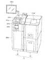
図2は、現金出納装置21の一例の外観を示す図である。現金出納装置21は、紙幣出納装置22および硬貨出納装置23を含む。紙幣出納装置22は、紙幣精算装置12へ装填する紙幣を出金し、紙幣精算装置12から回収した紙幣を入金する。硬貨出納装置23は、硬貨精算装置13へ装填する硬貨を出金し、硬貨精算装置13から回収した硬貨を入金する。  FIG. 2 is a diagram illustrating an appearance of an example of thecash accounting apparatus 21. Thecash accounting apparatus 21 includes abanknote accounting apparatus 22 and acoin accounting apparatus 23. The banknote depositing /dispensing device 22 dispenses banknotes to be loaded into the banknote settlement apparatus 12 and deposits banknotes collected from the banknote settlement apparatus 12. The coin depositing / dispensingapparatus 23 dispenses coins to be loaded into the coin settlement apparatus 13 and deposits coins collected from the coin settlement apparatus 13.

次に、紙幣処理装置としての紙幣出納装置22の構成について説明する。紙幣出納装置22は、筐体200aと、入金部210aと、出金部220aと、操作表示部295aとを備え、あとで詳しく説明するように紙幣操出ユニットから紙幣を受け入れ可能なように構成されている。ここで、紙幣操出ユニットとは、紙幣を繰出可能なユニットをいい、紙幣出納装置22の外部から紙幣を受け入れて1枚ずつ繰出す紙幣受入ユニット201aと、紙幣を内部に収容し、収納した紙幣を繰出す紙幣カセット30aとを含む。  Next, the structure of the banknote depositing / dispensingapparatus 22 as a banknote processing apparatus is demonstrated. The banknote depositing /dispensing device 22 includes ahousing 200a, adepositing unit 210a, adispensing unit 220a, and anoperation display unit 295a, and is configured to accept banknotes from the banknote handling unit as will be described in detail later. Has been. Here, the banknote handling unit refers to a unit capable of feeding out banknotes. Thebanknote receiving unit 201a that accepts banknotes from the outside of the banknote depositing / dispensingapparatus 22 and feeds them one by one; And abill cassette 30a for feeding bills.

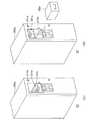
図4(A)および(B)に示すように、入金部210aは、搬送部230aの端部231aに設けられており、紙幣操出ユニットが装着(接続)可能なように構成されている。紙幣操出ユニットが入金部210aに装着された状態において、紙幣操出ユニットから繰出された紙幣は搬送部230aの端部231aを介して紙幣出納装置22内に搬送されることができる。このように、入金部210aは、紙幣操出ユニットから繰出された紙幣が搬送部230aの端部231aから機内に搬送されるように、紙幣操出ユニットと搬送部230aとを接続する。このため、入金部210aを紙幣操出ユニット接続部と呼ぶこともできる。例えば、店員が紙幣出納装置22へ紙幣を手動で入金する場合には、紙幣受入ユニット201aが入金部210aに装着される。一方、店員が紙幣出納装置22へ紙幣カセット30aを用いて紙幣を入金(以下、「カセット入金」ともいう。)する場合には、紙幣受入ユニット201aに代えて、紙幣カセット30aが入金部210aに装着される(図4(B)参照)。このように、紙幣出納装置22は、紙幣受入ユニット201aに代えて、入金部210aに紙幣カセット30aを着脱することができるように構成されている。  As shown in FIGS. 4A and 4B, thedepositing unit 210a is provided at theend 231a of thetransport unit 230a, and is configured such that the bill handling unit can be mounted (connected). In a state where the banknote handling unit is mounted on thedepositing unit 210a, the banknotes fed out from the banknote handling unit can be transported into the banknote depositing /dispensing device 22 via theend 231a of the transportingunit 230a. In this way, thedepositing unit 210a connects the banknote handling unit and thetransport unit 230a so that the banknotes fed out from the banknote handling unit are transported from theend 231a of thetransport unit 230a into the machine. For this reason, the money_receiving |payment part 210a can also be called a banknote handling unit connection part. For example, when a clerk manually deposits banknotes into the banknote depositing /dispensing device 22, thebanknote receiving unit 201a is mounted on thedepositing unit 210a. On the other hand, when a clerk deposits banknotes into the banknote depositing /dispensing device 22 using thebanknote cassette 30a (hereinafter also referred to as “cassette depositing”), thebanknote cassette 30a is replaced with thedepositing unit 210a instead of thebanknote receiving unit 201a. It is mounted (see FIG. 4B). Thus, the banknote depositing /dispensing device 22 is configured to be able to attach / detach thebanknote cassette 30a to / from thedepositing unit 210a instead of thebanknote receiving unit 201a.

なお、入金部210aは、紙幣受入ユニット201a及び紙幣カセット30aに限らず、他の形態の紙幣操出ユニットが接続可能なように構成されてもよい。  In addition, the money_receiving |payment part 210a may be comprised so that not only thebanknote acceptance unit 201a and thebanknote cassette 30a but the banknote handling unit of another form can be connected.

出金部220aは、紙幣を紙幣出納装置22の外部に投出するために設けられている。  Thedispensing unit 220a is provided for throwing out banknotes outside the banknote depositing /dispensing device 22.

操作表示部295aは、現金管理装置21、現金精算装置11および現金搬送カセット30の状態等を表示し、かつ、店員等の操作者が命令やデータを入力することができるように構成されている。操作表示部295aは、例えば、タッチパネル式ディスプレイ等でよい。なお、操作表示部295aは、紙幣出納装置22または硬貨出納装置23のいずれか一方に設けられ、それらの両方の情報を表示するために共通に用いられる。また、現金出納装置21の操作手段として、カードリーダ(図示せず)を紙幣出納装置22に設けてもよい。  Theoperation display unit 295a displays the state of thecash management device 21, the cash settlement apparatus 11, and the cash transport cassette 30, and is configured so that an operator such as a store clerk can input commands and data. . Theoperation display unit 295a may be a touch panel display, for example. In addition, theoperation display part 295a is provided in any one of the banknote depositing / dispensingapparatus 22 or the coin depositing / dispensingapparatus 23, and is used in common for displaying both information. Further, a card reader (not shown) may be provided in the banknote depositing / dispensingapparatus 22 as an operating means of thecash accounting apparatus 21.

図3は、紙幣出納装置22の構成例を示すブロック図である。紙幣出納装置22は、前述の入金部210a、出金部220aおよび操作表示部295aのほか、搬送部230aと、識別部240aと、収納部250aと、回収部255aと、リード・ライト部257aと、ユニット決定部260aと、機外リジェクト部222aと、機内リジェクト部224aと、メモリ270aと、通信部280aと、制御部290aとをさらに備えている。  FIG. 3 is a block diagram illustrating a configuration example of the banknote depositing /dispensing device 22. The banknote depositing /dispensing device 22 includes atransfer unit 230a, anidentification unit 240a, astorage unit 250a, arecovery unit 255a, a read /write unit 257a, in addition to thedeposit unit 210a, thewithdrawal unit 220a, and theoperation display unit 295a. ,Unit determination unit 260a, out-of-flight rejection unit 222a, in-flight rejection unit 224a,memory 270a,communication unit 280a, and control unit 290a.

搬送部230aは、紙幣操出ユニットが接続され、機内に受け入れた紙幣を搬送する。より詳しくは、搬送部230aは、入金部210aに装着された紙幣受入ユニット201aに投入された紙幣を収納部250aへ搬送し、あるいは、出金部220aから投出する紙幣を収納部250aから搬送する。また、搬送部230aは、収納部250aから紙幣カセット30aへ紙幣を搬送し、あるいは、紙幣カセット30aから収納部250aへ紙幣を搬送できるように構成されている。図4に示すように、搬送部230aおよび所定の部分にはフォトセンサ等のセンサ242aが設けられており、センサ242aは紙幣の有無や紙幣の通過を検知する。  Thetransport unit 230a is connected to a banknote handling unit and transports banknotes received in the machine. More specifically, thetransport unit 230a transports banknotes inserted into thebanknote receiving unit 201a attached to thedepositing unit 210a to thestorage unit 250a, or transports banknotes thrown out from thewithdrawal unit 220a from thestorage unit 250a. To do. Moreover, theconveyance part 230a is comprised so that a banknote can be conveyed from theaccommodating part 250a to thebanknote cassette 30a, or a banknote can be conveyed from thebanknote cassette 30a to theaccommodating part 250a. As shown in FIG. 4, asensor 242 a such as a photosensor is provided in thetransport unit 230 a and a predetermined portion, and thesensor 242 a detects the presence or absence of banknotes and the passage of banknotes.

識別部240aは、例えば、磁気センサ、蛍光センサ、金属スレッドセンサ、厚みセンサ、イメージセンサ等のセンサを備え、記憶している各紙幣の特徴とセンサの出力とを比較して、搬送部230aによって搬送される紙幣が受付可能な紙幣か受付できないリジェクト紙幣であるかを識別する。ここで、リジェクト紙幣は、例えば、紙幣以外の紙葉類、受付対象外の外国紙幣、破れや汚れのために識別できない紙幣である。また、搬送の際に、重なって搬送される紙幣や、紙幣同士の間隔が所定の間隔よりも狭い紙幣もリジェクト紙幣として扱われる。  Theidentification unit 240a includes, for example, sensors such as a magnetic sensor, a fluorescence sensor, a metal thread sensor, a thickness sensor, and an image sensor. Theidentification unit 240a compares the characteristics of each stored banknote with the output of the sensor, and theconveyance unit 230a It is identified whether the bill to be conveyed is a bill that can be accepted or a reject bill that cannot be accepted. Here, reject banknotes are, for example, paper sheets other than banknotes, foreign banknotes that are not accepted, and banknotes that cannot be identified due to tearing or dirt. Also, banknotes that are transported in an overlapping manner and banknotes in which the interval between the banknotes is narrower than a predetermined interval are handled as reject banknotes.

さらに、識別部240aは、リジェクト紙幣ではない紙幣について、その金種、真偽、正損(正券/損券)、新旧等を識別するように構成されている。ここで、正券および損券はいずれも金種の識別が可能な紙幣であるが、正券は流通に適した状態の紙幣をいい、損券は破れや汚れにより流通に適さない紙幣をいう。  Furthermore, theidentification unit 240a is configured to identify the denomination, authenticity, correctness (correct / lossy), old and new, etc., of a banknote that is not a reject banknote. Here, both the correct bill and the non-performing bill are banknotes whose denomination can be identified, but the correct bill refers to a banknote in a state suitable for distribution, and a non-slip sheet refers to a banknote that is not suitable for distribution due to tearing or dirt. .

収納部250aは、識別部240aにおいて識別された紙幣を金種ごとに収納するとともに、収納した紙幣を1枚ずつ繰出す。この収納部250aは、スタック式収納部でもよく、あるいは、テープリール式収納部であってもよい。回収部255aは、紙幣出納装置22の収納部250aに収納された紙幣を回収する際に用いられる。回収部255aはボックス、袋などで構成される。  Thestorage unit 250a stores the banknotes identified by theidentification unit 240a for each denomination and feeds the stored banknotes one by one. Thestorage unit 250a may be a stack type storage unit or a tape reel type storage unit. Thecollection unit 255a is used when collecting banknotes stored in thestorage unit 250a of the banknote depositing /dispensing device 22. Thecollection unit 255a is configured with a box, a bag, and the like.

リード・ライト部257aは、紙幣カセット30aに設けられた記憶部と有線または無線で通信可能に接続され、この記憶部に格納された情報を読み取り、あるいは、記憶部へ情報を書き込むことができるように構成されている。なお、この紙幣カセット30aの有する記憶部は、該紙幣カセット30aを特定するためのカセットID情報を少なくとも記憶し、必要に応じて、紙幣カセット30aに収容されている紙幣の金種や数量等の収納紙幣に関する情報を格納してもよい。また、リード・ライト部257aに代って通信部280aが、LAN等の通信回線を介して、紙幣カセット30aに紙幣を収納した紙幣精算装置12等から、カセットID以外の情報(収容紙幣の金種や数量等)を受信してもよい。  The read /write unit 257a is connected to a storage unit provided in thebanknote cassette 30a so as to be able to communicate with a wire or wirelessly, so that information stored in the storage unit can be read or information can be written to the storage unit. It is configured. In addition, the memory | storage part which thisbanknote cassette 30a has memorize | stores at least cassette ID information for specifying thisbanknote cassette 30a, and if necessary, denomination, quantity, etc. of the banknote accommodated in thebanknote cassette 30a are stored. Information about stored banknotes may be stored. In addition, thecommunication unit 280a replaces the read /write unit 257a with the information other than the cassette ID (the money of the stored banknote) from the banknote settlement apparatus 12 that stores banknotes in thebanknote cassette 30a via a communication line such as a LAN. Seed, quantity, etc.) may be received.

ユニット決定部260aは、紙幣を繰出す紙幣操出ユニットを決定する。より詳しくは、ユニット決定部260aは、紙幣操出ユニットの搬送部230aへの接続状況に基づいて、紙幣を繰出す紙幣操出ユニットを決定する。ユニット決定部260aは、セット検知センサおよびユニット接続用コネクタからの情報によって紙幣操出ユニットの搬送部230aへの接続状況を把握し、紙幣を繰出す紙幣操出ユニットを決定する。ここで、セット検知センサは、紙幣受入ユニット201aが入金部210aに装着されたことを検知するためのセンサであり、例えばフォトインタラプタで構成され、紙幣受入ユニット201aに設けられた遮光板がフォトインタラプタを遮光することにより検知する。ユニット接続用コネクタは、紙幣受入ユニット201aや紙幣カセット30aの端子(コネクタ)と接続され、駆動用の電源線や信号線を接続する。  Theunit determining unit 260a determines a banknote handling unit that pays out banknotes. In more detail, theunit determination part 260a determines the banknote handling unit which pays out a banknote based on the connection condition to theconveyance part 230a of a banknote handling unit. Theunit determination unit 260a grasps the connection status of the banknote handling unit to thetransport unit 230a based on information from the set detection sensor and the unit connection connector, and determines a banknote handling unit for feeding out banknotes. Here, the set detection sensor is a sensor for detecting that thebanknote receiving unit 201a is attached to thedepositing unit 210a. For example, the set detecting sensor is configured by a photo interrupter, and a light blocking plate provided in thebanknote receiving unit 201a is a photo interrupter. Is detected by shading. The unit connection connector is connected to a terminal (connector) of thebanknote receiving unit 201a or thebanknote cassette 30a, and connects a driving power line or signal line.

ユニット決定部260aは、ユニット接続用コネクタの通電状態から、紙幣操出ユニットが入金部210aに装着されているか否かを検知するとともに、セット検知センサにより、入金部210aに装着された紙幣操出ユニットの種類を検知する。  Theunit determination unit 260a detects whether or not the banknote handling unit is mounted on thedepositing unit 210a from the energized state of the unit connection connector, and the banknote handling mounted on thedepositing unit 210a by the set detection sensor. Detect unit type.

なお、紙幣出納装置22は、ユニット接続用コネクタを介して紙幣カセット30a内の記憶部にアクセス(リード、ライト)することができる。この場合、ユニット決定部260aは、記憶部に格納された識別情報により、紙幣操出ユニットの種類を知ることができる。また、紙幣受入ユニット201aが識別情報等を記憶する記憶部を有してもよい。この場合、ユニット決定部260aは、紙幣受入ユニット201aの記憶部に格納された識別情報により、紙幣操出ユニットの種類を知ることができる。  Note that the banknote depositing /dispensing device 22 can access (read, write) the storage unit in thebanknote cassette 30a via the unit connection connector. In this case, theunit determination part 260a can know the kind of banknote handling unit from the identification information stored in the storage part. Moreover, you may have a memory | storage part in which thebanknote acceptance unit 201a memorize | stores identification information etc. In this case, theunit determination part 260a can know the kind of banknote handling unit by the identification information stored in the memory | storage part of thebanknote acceptance unit 201a.

上記のセット検知センサおよびユニット接続用コネクタを用いる場合、ユニット決定部260aは、ユニット接続用コネクタにより紙幣操出ユニットの装着を検知し、かつ、セット検知センサにより紙幣受入ユニット201aの装着を検知したとき、紙幣受入ユニット201aから紙幣を繰出す決定をする。一方、ユニット接続用コネクタにより紙幣操出ユニットの装着を検知し、かつ、セット検知センサにより紙幣受入ユニット201aの装着を検知しないとき、ユニット決定部260aは紙幣カセット30aから紙幣を繰出す決定をする。  When the set detection sensor and the unit connection connector are used, theunit determination unit 260a detects the mounting of the banknote handling unit using the unit connection connector, and detects the mounting of thebanknote receiving unit 201a using the set detection sensor. Then, it decides to pay out banknotes from thebanknote receiving unit 201a. On the other hand, when the attachment of the banknote handling unit is detected by the unit connection connector and the installation of thebanknote receiving unit 201a is not detected by the set detection sensor, theunit determination unit 260a determines to feed the banknote from thebanknote cassette 30a. .

なお、ユニット決定部260aは、操作表示部295aや現金管理装置25等(以下、「処理受付部」という。)が受け付けた処理内容に基づいて、紙幣を繰出す紙幣操出ユニットを決定してもよい。これにより、例えば、後述の紙幣処理装置22Xのように、紙幣受入ユニット201a及び紙幣カセット30aの両方を同時に装着可能な場合に、どちらから紙幣を繰出すのかをユーザが処理受付部を介して指示できるようになる。  Theunit determination unit 260a determines a banknote handling unit that feeds out banknotes based on the processing content received by theoperation display unit 295a, thecash management device 25, or the like (hereinafter referred to as “processing reception unit”). Also good. Thereby, for example, when both thebanknote receiving unit 201a and thebanknote cassette 30a can be simultaneously mounted as in thebanknote processing apparatus 22X described later, the user instructs the banknote from which the banknote is fed out via the process receiving unit. become able to.

機外リジェクト部222a及び機内リジェクト部224aはともに、リジェクト紙幣を集積するために設けられている。機外リジェクト部222aは、識別部240aによりリジェクト紙幣であると識別された紙幣を紙幣出納装置22の外部から取り出し可能にする。一方、機内リジェクト部224aは、識別部240aによりリジェクト紙幣であると識別された紙幣を紙幣出納装置22内にセキュリティが確保された状態で収容する。この機内リジェクト部224aは、筐体200aの内部に設けられており、装置内にリジェクト紙幣を収納する。このため、店員等の管理権限のないユーザが機内リジェクト部224a内の紙幣を取り出すことはできない。  Both the out-of-machine reject unit 222a and the in-flight reject unit 224a are provided for accumulating reject banknotes. The out-of-machine rejection unit 222a enables the banknote identified as a reject banknote by theidentification unit 240a to be taken out from the banknote depositing /dispensing device 22. On the other hand, the in-flight reject unit 224a accommodates the banknote identified as a reject banknote by theidentification unit 240a in the banknote depositing /dispensing device 22 in a state where security is ensured. This in-machine reject unit 224a is provided inside thehousing 200a and stores reject banknotes in the apparatus. For this reason, a user without management authority such as a store clerk cannot take out the banknote in the in-flight reject unit 224a.

メモリ270aは、紙幣出納装置22を制御する各種プログラムおよびデータを格納するROMまたはHDD、および、プログラムのロード領域やプログラム実行時における作業領域となるRAM等を含む。さらに、メモリ270aは、収納部250aおよび回収部255aに収納されている紙幣の情報(金種や正損別の数量等)も記憶している。さらに、メモリ270aは、紙幣出納装置22が行った処理内容(日時、処理種別、紙幣の搬送先、処理した紙幣の金種や正損別枚数、および操作者IDなど)を記憶する。また、収納部250aがテープリール式収納部である場合、メモリ270aは、収納部250aが収納している紙幣の収納順と、各紙幣の金種・正損等の情報とを記憶する。  Thememory 270a includes a ROM or HDD that stores various programs and data for controlling the banknote depositing /dispensing device 22, and a RAM that serves as a work load area and a work area during program execution. Furthermore, thememory 270a also stores information on banknotes stored in thestorage unit 250a and therecovery unit 255a (denominations, quantities by correct / loss, etc.). Furthermore, thememory 270a stores the details of processing performed by the banknote depositing / dispensing device 22 (date and time, processing type, banknote transport destination, number of processed banknote denominations and correct / incorrect numbers, operator ID, and the like). Further, when thestorage unit 250a is a tape reel storage unit, thememory 270a stores the storage order of banknotes stored in thestorage unit 250a and information such as denominations and correctness of each banknote.

通信部280aは、現金処理システム1を構成する他の装置(現金精算装置11、現金管理装置25、POS管理装置26等)と通信するために設けられている。  Thecommunication part 280a is provided in order to communicate with other apparatuses (cash settlement apparatus 11,cash management apparatus 25,POS management apparatus 26, etc.) which comprise thecash processing system 1. FIG.

制御部290aは、メモリ270a内のプログラムを実行して紙幣出納装置22の全体を制御するように構成されている。識別部240aが紙幣操出ユニットから受け入れられた紙幣をリジェクト紙幣と識別したとき、制御部290aは、その紙幣を繰出した紙幣操出ユニットに基づいて、リジェクト紙幣の搬送先を機内リジェクト部224aと機外リジェクト部222aとのいずれかに決定する。例えば、制御部290aは、紙幣受入ユニット201aから受け入れたリジェクト紙幣については搬送先を機外リジェクト部222aに決定し、紙幣カセット30aから受け入れたリジェクト紙幣については搬送先を機内リジェクト部224aに決定する。そして、制御部290aはリジェクト紙幣が決定された搬送先に搬送されるように搬送部230aを制御する。  The control unit 290a is configured to execute the program in thememory 270a to control the entire banknote depositing /dispensing device 22. When theidentification unit 240a identifies the banknote received from the banknote handling unit as the reject banknote, the control unit 290a determines the transport destination of the reject banknote as the in-machine reject unit 224a based on the banknote handling unit that has fed out the banknote. It is determined as any one of theexternal rejection unit 222a. For example, the control unit 290a determines that the reject banknote received from thebanknote receiving unit 201a is theoutside reject unit 222a, and the reject banknote received from thebanknote cassette 30a is the in-machine reject unit 224a. . Then, the control unit 290a controls thetransport unit 230a so that the reject banknote is transported to the determined transport destination.

なお、紙幣カセット30a内の紙幣は、紙幣カセット30aに収納されるときに一度識別されているため、全てリジェクト紙幣ではないとも思われる。しかしながら、実際には装置ごとの識別部の特性やレベル設定の相違によって、カセット入金の際、正券と判断された紙幣でも損券やリジェクト紙幣と判定されることがある。また、リジェクト紙幣を含めた回収処理が行われた場合、紙幣カセット30aにリジェクト紙幣が収納される可能性がある。  In addition, since the banknote in thebanknote cassette 30a is identified once when accommodated in thebanknote cassette 30a, it is thought that it is not all reject banknotes. However, in reality, depending on the characteristics of the identification unit and the level setting for each device, a banknote that is determined to be a correct one may be determined as a damaged or rejected banknote when depositing a cassette. Moreover, when the collection | recovery process including a reject banknote is performed, a reject banknote may be accommodated in thebanknote cassette 30a.

次に、図4を参照して、紙幣出納装置22の内部構成の一例を説明する。  Next, an example of the internal configuration of the banknote depositing /dispensing device 22 will be described with reference to FIG.

図4(A)および図4(B)は、紙幣出納装置22の内部構成の一例を示す断面図である。図4(A)は、入金部210aに紙幣受入ユニット201aを装着した状態を示し、図4(B)は、入金部210aに紙幣カセット30aを装着した状態を示す。なお、操作表示部295aについては、図4においてその図示を省略している。  4A and 4B are cross-sectional views showing an example of the internal configuration of the banknote depositing /dispensing device 22. FIG. 4A shows a state where thebanknote receiving unit 201a is mounted on thedepositing unit 210a, and FIG. 4B shows a state where thebanknote cassette 30a is mounted on thedepositing unit 210a. Theoperation display unit 295a is not shown in FIG.

店員は、紙幣受入ユニット201aを用いて紙幣を紙幣出納装置22に入金する場合、図4(A)に示すように、入金部210aに紙幣受入ユニット201aを装着する。これにより、ユニット決定部260aは紙幣受入ユニット201aを紙幣操出ユニットと決定し、紙幣受入ユニット201aに投入された紙幣は搬送部230aに繰出される。  When the clerk deposits a banknote into the banknote depositing /dispensing device 22 using thebanknote receiving unit 201a, the bank clerk attaches thebanknote receiving unit 201a to thedepositing unit 210a as shown in FIG. Thereby, theunit determination part 260a determines thebanknote acceptance unit 201a as a banknote handling unit, and the banknote thrown into thebanknote acceptance unit 201a is drawn | fed out to theconveyance part 230a.

一方、店員は、紙幣カセット30a内の紙幣を紙幣出納装置22に入金する場合、図4(B)に示すように、入金部210aに紙幣カセット30aを装着する。これにより、ユニット決定部260aは紙幣カセット30aを紙幣操出ユニットと決定し、紙幣カセット30aに収容された紙幣は搬送部230aに繰出される。  On the other hand, when the clerk deposits the banknote in thebanknote cassette 30a into the banknote depositing / dispensingapparatus 22, thebanknote cassette 30a is mounted on thedepositing unit 210a as shown in FIG. Thereby, theunit determination part 260a determines thebanknote cassette 30a as a banknote handling unit, and the banknote accommodated in thebanknote cassette 30a is drawn | fed out to theconveyance part 230a.

紙幣出納装置22から紙幣を出金する場合には、収納部250aは、紙幣を一枚ずつ搬送部230aへ繰り出す。搬送部230aは、繰り出された紙幣を出金部220aへ搬送し、その紙幣を投出する。  When the banknotes are withdrawn from the banknote depositing /dispensing device 22, thestorage unit 250a feeds the banknotes one by one to thetransport unit 230a. Thetransport unit 230a transports the fed banknotes to thewithdrawal unit 220a and throws out the banknotes.

このように、紙幣出納装置22は、紙幣受入ユニット201aに投入された紙幣を収納部250aへ収納し、逆に、収納部250aに収納された紙幣を出金部220aへ投出することができる。即ち、紙幣出納装置22は、入金された紙幣を出金に再利用することができるように構成されている。  Thus, the banknote depositing /dispensing device 22 stores the banknotes inserted into thebanknote receiving unit 201a in thestorage unit 250a, and conversely, can throw out banknotes stored in thestorage unit 250a to thewithdrawal unit 220a. . That is, the banknote depositing /dispensing device 22 is configured so that the deposited banknote can be reused for dispensing.

紙幣を紙幣精算装置12へ装填する場合、紙幣を紙幣カセット30aへ搬送するために、収納部250aが紙幣を一枚ずつ搬送部230aへ繰り出す。搬送部230aは、繰り出された紙幣を紙幣現金搬送カセット30aへ出金する。これにより、紙幣出納装置22は、紙幣精算装置12へ装填する紙幣を紙幣カセット30aへ出金することができる。紙幣精算装置12から紙幣を回収する場合、紙幣カセット30aがその中にある紙幣を一枚ずつ搬送部230aへ繰り出す。搬送部230aは、繰り出された紙幣を収納部250aへ収納する。  When loading banknotes into the banknote settlement apparatus 12, thestorage unit 250a feeds banknotes one by one to thetransport unit 230a in order to transport the banknotes to thebanknote cassette 30a. Thetransport unit 230a withdraws the fed banknotes to the banknotecash transport cassette 30a. Thereby, the banknote depositing / dispensingapparatus 22 can withdraw the banknote loaded into the banknote settlement apparatus 12 to thebanknote cassette 30a. When collecting banknotes from the banknote settlement apparatus 12, thebanknote cassette 30a feeds banknotes therein one by one to thetransport unit 230a. Thetransport unit 230a stores the fed banknote in thestorage unit 250a.

このように、紙幣出納装置22は、紙幣精算装置12へ装填される紙幣を紙幣カセット30aへ出金し、あるいは、紙幣精算装置12から回収された紙幣を紙幣カセット30aから入金することができるように構成されている。  Thus, the banknote depositing /dispensing device 22 can withdraw banknotes loaded into the banknote settlement apparatus 12 to thebanknote cassette 30a, or deposit banknotes collected from the banknote settlement apparatus 12 from thebanknote cassette 30a. It is configured.

次に、紙幣出納装置22の入出金処理について図面を用いてより詳しく説明する。紙幣出納装置22の入出金処理は、入金、出金、補充および回収の4つに大別される。それぞれの処理について、図5〜図7を用いて説明する。  Next, the deposit / withdrawal process of the banknote depositing /dispensing device 22 will be described in more detail with reference to the drawings. The deposit / withdrawal process of the banknote depositing /dispensing device 22 is roughly classified into four types, that is, deposit, withdrawal, replenishment, and collection. Each process will be described with reference to FIGS.

(入金処理)
入金処理は、紙幣を紙幣出納装置22に入金する処理であり、例えば、紙幣精算装置12から回収された紙幣を紙幣出納装置22に入金する際に行われる。紙幣の入金は、紙幣受入ユニット201a及び紙幣カセット30aのいずれを用いても可能である。
(Deposit processing)
The depositing process is a process of depositing banknotes into the banknote depositing / dispensingapparatus 22, and is performed when depositing banknotes collected from the banknote settlement apparatus 12 into the banknote depositing / dispensingapparatus 22, for example. Banknotes can be deposited using either thebanknote receiving unit 201a or thebanknote cassette 30a.

図5(A)は、入金部210aに紙幣受入ユニット201aが装着されている場合における、入金される紙幣の搬送経路を示している(経路a、経路bおよび経路c)。  FIG. 5 (A) shows a transport path of banknotes to be deposited when thebanknote receiving unit 201a is attached to thedepositing unit 210a (path a, path b and path c).

店員が紙幣受入ユニット201aへ紙幣を投入し、処理受付部が入金指示を受け付けると、紙幣受入ユニット201aは投入された紙幣を一枚ずつ搬送部230aへ繰り出す。搬送部230aは、繰り出された紙幣を識別部240aに通過させ、リジェクト紙幣であるか否かを識別する。その結果、(リジェクト紙幣ではない)正常な紙幣の場合、搬送部230aはその紙幣を金種に対応する収納部250aに搬送する(図5(A)の経路a)。なお、搬送部230aは、正常な紙幣であっても、収納部250aがフルの場合、その紙幣を回収集積部254aに搬送する(図5(A)の経路c)。回収集積部254aは搬送されてきた紙幣を集積するとともに、回収集積部254aの底面を開放して集積した紙幣を落下させる。これにより、回収集積部254aに集積された紙幣は回収部255aに収納される。回収集積部254aに集積された紙幣がフル枚数(集積可能な最大枚数)を超えたときは、回収集積部254aへの紙幣の搬送を停止し、集積された紙幣を回収部255aに収納した後、搬送を再開する。  When the store clerk inserts banknotes into thebanknote receiving unit 201a and the processing reception unit receives a deposit instruction, thebanknote receiving unit 201a feeds the inserted banknotes one by one to thetransport unit 230a. Thetransport unit 230a passes the fed banknote through theidentification unit 240a and identifies whether the banknote is a reject banknote. As a result, in the case of a normal banknote (not a reject banknote), thetransport unit 230a transports the banknote to thestorage unit 250a corresponding to the denomination (path a in FIG. 5A). In addition, even if it is a normal banknote, if theaccommodating part 250a is full, theconveyance part 230a will convey the banknote to the collection |recovery stacking part 254a (path | route c of FIG. 5 (A)). The collection andaccumulation unit 254a accumulates the banknotes that have been conveyed, and drops the accumulated banknotes by opening the bottom surface of the collection andaccumulation unit 254a. As a result, the banknotes accumulated in the collection / stackingunit 254a are stored in thecollection unit 255a. After the banknotes accumulated in the collection / stackingunit 254a exceed the full number (maximum number of sheets that can be stacked), the conveyance of the banknotes to the collection / stackingunit 254a is stopped and the collected banknotes are stored in thecollection unit 255a. , Resume transport.

一方、識別部240aによりリジェクト紙幣と識別された場合、搬送部230aは、そのリジェクト紙幣を機外リジェクト部222aへ搬送する(図5(A)の経路b)。  On the other hand, when therecognition unit 240a identifies the reject banknote, thetransport unit 230a transports the reject banknote to theexternal rejection unit 222a (path b in FIG. 5A).

図5(B)は、入金部210aに紙幣カセット30aが装着されている場合における、入金される紙幣の搬送経路(経路a、経路bおよび経路c)を示している。  FIG. 5B shows a transport path (path a, path b, and path c) of banknotes to be deposited when thebanknote cassette 30a is attached to thedepositing unit 210a.

処理受付部が入金指示を受け付けると、紙幣カセット30aはその内部に収容された紙幣を一枚ずつ搬送部230aに繰出す。搬送部230aは繰り出された紙幣を識別部240aに通過させ、識別部240aはリジェクト紙幣であるか否かを識別する。その結果、正常な紙幣の場合、搬送部230aは、その紙幣を金種に対応する収納部250aに搬送する(図5(B)の経路a)。なお、搬送部230aは、正常な紙幣であっても、収納部250aがフルの場合、その紙幣を回収集積部254aに搬送し、回収部255aに収納する(図5(B)の経路c)。  When the processing accepting unit accepts the deposit instruction, thebill cassette 30a feeds the bills stored therein one by one to thetransport unit 230a. Thetransport unit 230a passes the fed banknote through theidentification unit 240a, and theidentification unit 240a identifies whether the banknote is a reject banknote. As a result, in the case of a normal banknote, thetransport unit 230a transports the banknote to thestorage unit 250a corresponding to the denomination (path a in FIG. 5B). Even if thetransport unit 230a is a normal banknote, when thestorage unit 250a is full, thetransport unit 230a transports the banknote to the collection / stackingunit 254a and stores it in therecovery unit 255a (path c in FIG. 5B). .

一方、識別部240aによりリジェクト紙幣と識別された場合、搬送部230aは、そのリジェクト紙幣を機内リジェクト部224aに搬送する(図5(B)の経路b)。  On the other hand, when it is identified as a reject banknote by theidentification unit 240a, thetransport unit 230a transports the reject banknote to the in-flight reject unit 224a (path b in FIG. 5B).

上記のように、紙幣出納装置22は、紙幣受入ユニット201aから繰出された紙幣か紙幣カセット30aから繰出された紙幣かによって、機内に受け入れられたリジェクト紙幣の搬送先を変える。より具体的には、紙幣受入ユニット201aから繰出された紙幣の場合には、制御部290aは、リジェクト紙幣を機外リジェクト部222aに搬送するように搬送部230aを制御する。一方、紙幣カセット30aから繰出された紙幣の場合には、制御部290aはリジェクト紙幣を機内リジェクト部224aに搬送するように搬送部230aを制御する。なお、入金処理の内容はメモリ270aに記憶される。  As described above, the banknote depositing /dispensing device 22 changes the transport destination of the reject banknote received in the machine depending on whether the banknote is fed from thebanknote receiving unit 201a or the banknote fed from thebanknote cassette 30a. More specifically, in the case of a banknote fed out from thebanknote receiving unit 201a, the control unit 290a controls thetransport unit 230a so as to transport the reject banknote to theexternal reject unit 222a. On the other hand, in the case of a banknote fed out from thebanknote cassette 30a, the control unit 290a controls thetransport unit 230a so as to transport the reject banknote to the in-machine reject unit 224a. The contents of the deposit process are stored in thememory 270a.

このように、紙幣カセット30a内のリジェクト紙幣については、筐体200aの内部に設けられた機内リジェクト部224aに搬送・収容することにより、店員等の管理権限のないユーザが紙幣カセット30a内に収容された紙幣に触れることはできず、紙幣カセット30a内の紙幣に対するセキュリティを維持することができる。また、カセット入金する際、紙幣出納装置22が紙幣カセット30a内の紙幣の収納順序および金種や正損等の各紙幣の情報を、例えば紙幣カセット30aの記憶部から把握可能な場合には、この情報に基づき、紙幣出納装置22で識別を行わずに入金処理を行うこともできる。  Thus, about the reject banknote in thebanknote cassette 30a, a user without management authority, such as a salesclerk, accommodates in thebanknote cassette 30a by conveying and accommodating to the in-machine rejection part 224a provided in the inside of the housing | casing 200a. The bill cannot be touched, and security for the bill in thebill cassette 30a can be maintained. In addition, when depositing a cassette, when the banknote depositing /dispensing device 22 can grasp the storage order of banknotes in thebanknote cassette 30a and information of each banknote such as denomination and correctness from the storage unit of thebanknote cassette 30a, for example, Based on this information, the banknote depositing /dispensing device 22 can perform the depositing process without performing identification.

(出金処理)
出金処理は、紙幣出納装置22から紙幣を出金する処理であり、例えば、紙幣精算装置12に紙幣を補充する際に行われる。紙幣の出金は、紙幣受入ユニット201a及び紙幣カセット30aのいずれを用いても可能である。図6(A)および図6(B)はそれぞれ、入金部210aに紙幣受入ユニット201aおよび紙幣カセット30aが装着されている場合における、出金される紙幣の搬送経路を示している(経路aおよび経路b)。
(Withdrawal processing)
The withdrawal process is a process of withdrawing banknotes from the banknote depositing /dispensing device 22 and is performed, for example, when the banknote settlement apparatus 12 is replenished with banknotes. Banknotes can be withdrawn using either thebanknote receiving unit 201a or the banknote cassette 30a. 6 (A) and 6 (B) respectively show the transport paths of the banknotes to be dispensed when thebanknote receiving unit 201a and thebanknote cassette 30a are attached to thedepositing section 210a (path a and Path b).

処理受付部が出金指示を受け付けると、収納部250aは収納された紙幣を一枚ずつ搬送部230aへ繰り出す。搬送部230aは繰り出された紙幣をセンサ242aに通過させ、センサ242aはリジェクト紙幣であるか否かを識別する。その結果、正常な紙幣の場合、搬送部230aはその紙幣を、紙幣受入ユニット201aが装着されているときには出金部220aに搬送し、紙幣カセット30aが装着されているときには紙幣カセット30aに搬送する(図6(A)及び(B)の経路a)。  When the processing acceptance unit accepts the withdrawal instruction, thestorage unit 250a feeds the stored banknotes one by one to thetransport unit 230a. Thetransport unit 230a passes the fed banknote through thesensor 242a, and thesensor 242a identifies whether the banknote is a reject banknote. As a result, in the case of a normal banknote, thetransport unit 230a transports the banknote to thewithdrawal unit 220a when thebanknote receiving unit 201a is mounted, and transports the banknote to thebanknote cassette 30a when thebanknote cassette 30a is mounted. (Route a in FIGS. 6A and 6B).

紙幣カセット30aに搬送された紙幣は紙幣カセット30aに収納され、紙幣カセット30aの記憶部は収納する紙幣の金種別枚数を記憶する。紙幣カセット30aがテープリール式の場合には、記憶部は紙幣の収納順と、各紙幣の金種・正損等の情報を記憶する。  The banknotes conveyed to thebanknote cassette 30a are stored in thebanknote cassette 30a, and the storage unit of thebanknote cassette 30a stores the number of denominations of banknotes stored. When thebill cassette 30a is a tape reel type, the storage unit stores information such as the storing order of bills and the denomination and correctness of each bill.

一方、センサ242aによりリジェクト紙幣と識別された場合、入金部210aに装着された紙幣操出ユニットによらず、搬送部230aはそのリジェクト紙幣を機内リジェクト部224aに搬送する(図6(A)及び(B)の経路b)。なお、出金処理の内容はメモリ270aに記憶される。  On the other hand, when thesensor 242a identifies the banknote as a reject banknote, thetransport section 230a transports the reject banknote to the in-machine reject section 224a regardless of the banknote handling unit attached to thedepositing section 210a (FIG. 6A and FIG. 6). (B) path b). The contents of the withdrawal process are stored in thememory 270a.

(補充処理)
補充処理は、紙幣出納装置22に紙幣を補充する処理であり、例えば、金庫にある紙幣を紙幣出納装置22に入金する際に行われる。処理受付部が補充指示を受け付けると、入金処理と同様に補充処理が行われる。
(Replenishment process)
The replenishment process is a process of replenishing banknotes in the banknote depositing /dispensing device 22 and is performed, for example, when depositing banknotes in a safe into the banknote depositing / dispensingapparatus 22. When the process accepting unit accepts the replenishment instruction, the replenishment process is performed in the same manner as the deposit process.

図7(A)は、紙幣受入ユニット201aから補充された紙幣の搬送経路を示している。即ち、図7(A)の経路aは識別部240aにより正常と識別された紙幣の搬送経路を示し、経路bは識別部240aによりリジェクト紙幣と識別された紙幣の搬送経路を示している。図7(A)からわかるように、補充処理における紙幣の搬送経路は、入金処理における紙幣の搬送経路(図5(A)の経路a及び経路b)と同様である。なお、補充処理の内容はメモリ270aに記憶される。  FIG. 7A shows a conveyance path of banknotes replenished from thebanknote receiving unit 201a. That is, a path a in FIG. 7A indicates a conveyance path of a banknote identified as normal by theidentification unit 240a, and a path b indicates a conveyance path of a banknote identified as a reject banknote by theidentification unit 240a. As can be seen from FIG. 7A, the banknote transport path in the replenishment process is the same as the banknote transport path in the deposit process (path a and path b in FIG. 5A). The contents of the replenishment process are stored in thememory 270a.

(回収処理)
回収処理は、紙幣出納装置22内の紙幣を回収する処理であり、例えば、紙幣出納装置22内の紙幣を金庫に出金する際に行われる。図7(B)は、回収処理時における、収納部250aに収納された紙幣の搬送経路を示している。即ち、図7(B)の経路aはセンサ242aにより正常と識別された紙幣の搬送経路を示し、経路bはセンサ242aによりリジェクト紙幣と識別された紙幣の搬送経路を示している。
(Recovery processing)
The collection process is a process of collecting banknotes in the banknote depositing / dispensingapparatus 22 and is performed, for example, when the banknotes in the banknote depositing / dispensingapparatus 22 are withdrawn to a safe. FIG. 7B shows a conveyance path of banknotes stored in thestorage unit 250a during the collection process. That is, the path a in FIG. 7B indicates a banknote transport path identified as normal by thesensor 242a, and the path b indicates a banknote transport path identified as a reject banknote by thesensor 242a.

図7(B)に示すように、回収処理では、処理受付部が回収指示を受け付けると、収納部250a内の正常紙幣は回収部255aに搬送され、リジェクト紙幣は機内リジェクト部224aに搬送される。回収部255aに搬送された紙幣は、管理権限を有するユーザによって紙幣出納装置22の外部に取り出される。回収処理の途中で回収部255aがフルになった場合には、回収部255aを空のものと交換することにより、回収処理を継続することができる。なお、回収処理の内容はメモリ270aに記憶される。  As shown in FIG. 7B, in the collection process, when the processing reception unit receives the collection instruction, the normal banknote in thestorage unit 250a is transported to therecovery unit 255a, and the reject banknote is transported to the in-machine reject unit 224a. . The banknotes conveyed to thecollection unit 255a are taken out of the banknote depositing /dispensing device 22 by a user having management authority. When therecovery unit 255a becomes full during the recovery process, the recovery process can be continued by replacing therecovery unit 255a with an empty one. The contents of the collection process are stored in thememory 270a.

なお、入金処理および補充処理において、識別部240aにより特定種別の紙幣であると識別された紙幣については、紙幣受入ユニット201aから入金された場合であっても、搬送部230aはその紙幣を機内リジェクト部224aに搬送するようにしてもよい。例えば、EC協議会規定1338の第6項に定められたカテゴリー2の紙幣(偽造紙幣)やカテゴリー3の紙幣(真偽不確定)と識別された紙幣については、その流通を阻止するため、紙幣操出ユニットの種別にかかわらず機内リジェクト部224aに搬送することが好ましい。  Note that, in the deposit process and the replenishment process, for the banknote identified by the identifyingunit 240a as a specific type of banknote, thetransport unit 230a rejects the banknote even if it is deposited from thebanknote receiving unit 201a. You may make it convey to thepart 224a. For example, for banknotes identified as category 2 banknotes (counterfeit banknotes) or category 3 banknotes (authenticity uncertain) as defined in paragraph 6 of EC Council Regulations 1338, It is preferable to carry to the in-flight rejection unit 224a regardless of the type of operation unit.

また、紙幣カセット30aから受け入れられたリジェクト紙幣の搬送先の変更は、処理受付部からの指示に限らず、紙幣カセット30aの有する記憶部に格納された、収納紙幣に関する情報に基づいて行ってもよい。例えば、紙幣カセット30aからN番目に紙幣以外の紙葉類(小切手等)が繰出されることを示す情報が紙幣カセット30aの記憶部に格納されている場合、制御部290aは、紙幣カセットからN番目に繰出された紙葉類については機外リジェクト部222aに搬送する制御を行うようにしてもよい。  Moreover, even if it changes based on the information regarding the stored banknote stored in the memory | storage part which not only the instruction | indication from a process reception part but thebanknote cassette 30a has received the change of the conveyance destination of the reject banknote received from thebanknote cassette 30a. Good. For example, when information indicating that paper sheets other than banknotes (checks, etc.) are fed out from thebanknote cassette 30a to the Nth is stored in the storage unit of thebanknote cassette 30a, the control unit 290a Control may be performed so that the second fed paper sheet is conveyed to the out-of-machine rejection unit 222a.

上記の紙幣出納装置22は紙幣操出ユニットとして紙幣受入ユニット201aおよび紙幣カセット30aのいずれかを入金部210aに装着するものであったが、本発明はこれに限らない。即ち、本発明は、紙幣受入ユニット201a及び紙幣カセット30aの両方を同時に装着可能な紙幣出納装置を含む。  Although the banknote depositing /dispensing device 22 is one for mounting either thebanknote receiving unit 201a or thebanknote cassette 30a as a banknote handling unit to thedepositing unit 210a, the present invention is not limited to this. That is, this invention includes the banknote depositing / dispensing apparatus which can mount | wear with both thebanknote acceptance unit 201a and thebanknote cassette 30a simultaneously.

図8は、そのような紙幣出納装置22Xの内部構成を示す断面図である。紙幣出納装置22Xには、紙幣受入ユニット201aおよび紙幣カセット30aの両方が装着されている。  FIG. 8 is a cross-sectional view showing the internal configuration of such a banknote depositing /dispensing apparatus 22X. Both thebanknote acceptance unit 201a and thebanknote cassette 30a are attached to the banknote depositing /dispensing apparatus 22X.

図8に示すように、搬送部230aは、紙幣受入ユニット201aおよび紙幣カセット30aのいずれかからであっても紙幣を機内の所定の部分(収納部250a、機内リジェクト部224a、機外リジェクト部222aおよび回収集積部254a)に搬送可能なように構成されている。また、図8に示すように、紙幣受入ユニット201aから繰出された紙幣と紙幣カセット30aから繰出された紙幣とに対して共通の搬送部230aに識別部240aが設けられている。  As shown in FIG. 8, thetransport unit 230a can transfer the banknotes to predetermined portions (astorage unit 250a, an in-machine reject unit 224a, an out-of-machine reject unit 222a) even from either thebanknote receiving unit 201a or thebanknote cassette 30a. And can be transported to the collecting and accumulatingunit 254a). Moreover, as shown in FIG. 8, theidentification part 240a is provided in thecommon conveyance part 230a with respect to the banknote paid out from thebanknote acceptance unit 201a, and the banknote extended from thebanknote cassette 30a.

制御部290aは、紙幣受入ユニット201aから受け入れられたリジェクト紙幣については機外リジェクト部222aへ搬送する制御を行い、紙幣カセット30aから受け入れられたリジェクト紙幣については機内リジェクト部224aへ搬送する制御を行う。  The control unit 290a performs control for conveying the reject banknote received from thebanknote receiving unit 201a to theexternal rejection unit 222a, and performs control for transporting the reject banknote received from thebanknote cassette 30a to the in-machine rejection unit 224a. .

なお、紙幣出納装置22Xにおいて、ユーザは処理受付部に指示を与えることで紙幣操出ユニットを任意に選択することができる。ユニット決定部260aは、処理受付部が受け付けた処理内容に基づいて、紙幣を繰出す紙幣繰出ユニットを決定する。  In the banknote depositing /dispensing apparatus 22X, the user can arbitrarily select a banknote handling unit by giving an instruction to the processing reception unit. Theunit determination unit 260a determines a banknote feeding unit that feeds banknotes based on the processing content received by the processing reception unit.

上記の説明では、紙幣出納装置22,22Xには2種類の紙幣操出ユニット(紙幣受入ユニット201a及び紙幣カセット30a)が装着可能であったが、本発明はこれに限らず、3種類以上の紙幣操出ユニットから紙幣を受入可能な紙幣出納装置に適用することができる。  In the above description, two types of banknote handling units (thebanknote receiving unit 201a and thebanknote cassette 30a) can be mounted on the banknote depositing /dispensing devices 22 and 22X. However, the present invention is not limited to this, and there are three or more types. The present invention can be applied to a banknote depositing / dispensing apparatus that can receive banknotes from a banknote handling unit.

上述のように、本実施形態に係る紙幣処理装置22は、少なくとも2種類の紙幣繰出ユニット(例えば、紙幣受入ユニット201a及び紙幣カセット30a)から紙幣を受け入れ可能であり、紙幣処理装置22内にリジェクト紙幣を収納する機内リジェクト部224aと、紙幣処理装置22外にリジェクト紙幣を投出する機外リジェクト部222aとを備えるとともに、紙幣を繰出す紙幣繰出ユニットを決定するユニット決定部260aと、識別部240aが紙幣操出ユニットから受け入れられた紙幣をリジェクト紙幣と識別したとき、その紙幣を繰出した紙幣繰出ユニットに基づいて、リジェクト紙幣の搬送先を機内リジェクト部224aと機外リジェクト部222aとのいずれかに決定する制御部290aとを備える。  As described above, thebanknote handling apparatus 22 according to the present embodiment can accept banknotes from at least two types of banknote feeding units (for example, thebanknote receiving unit 201a and thebanknote cassette 30a), and is rejected in thebanknote handling apparatus 22. Aunit determination unit 260a for determining a banknote feeding unit for feeding out banknotes, and an in-machine rejection unit 224a for storing banknotes and an externalmachine rejection unit 222a for throwing out rejected banknotes out of thebanknote processing device 22 When the banknote accepted by thebanknote handling unit 240a is identified as a reject banknote, the destination of the reject banknote is either the in-machine reject unit 224a or the out-of-machine reject unit 222a based on the banknote feeding unit that has fed out the banknote. And a control unit 290a for determining the above.

このような紙幣処理装置22によれば、紙幣を繰出した紙幣操出ユニットに応じて、リジェクト紙幣の搬送先は機内リジェクト部224aまたは機外リジェクト部222aに自動的に決定される。その結果、紙幣処理装置22のユーザからリジェクト紙幣の搬送先を指示することが不要となり、紙幣出納装置22の使いやすさを向上させることができる。  According to such abanknote processing apparatus 22, according to the banknote handling unit which picked up the banknote, the conveyance destination of a reject banknote is automatically determined to the in-machine rejection part 224a or theexternal rejection part 222a. As a result, it becomes unnecessary to instruct the transport destination of the rejected banknote from the user of thebanknote handling apparatus 22, and the usability of the banknote depositing / dispensingapparatus 22 can be improved.

また、本実施形態に係る紙幣処理装置22においては、前述のように、ユニット決定部260aは、紙幣繰出ユニットの搬送部230aへの接続状況に基づいて、紙幣を繰出す紙幣繰出ユニットを決定する。これにより、ユニット決定部260aはユーザからの指示がなくとも、紙幣を繰出す紙幣繰出ユニットを決定することができる。  Moreover, in thebanknote processing apparatus 22 which concerns on this embodiment, as above-mentioned, theunit determination part 260a determines the banknote delivery unit which pays out a banknote based on the connection condition to theconveyance part 230a of a banknote delivery unit. . Thereby, theunit determination part 260a can determine the banknote delivery unit which pays out a banknote, even if there is no instruction | indication from a user.

また、本実施形態に係る紙幣処理装置22は、前述のように、処理を受け付ける処理受付部(操作表示部295aや現金管理装置25等)をさらに備えるとともに、ユニット決定部260aは、処理受付部によって受け付けた処理内容に基づいて、紙幣を繰出す紙幣繰出ユニットを決定する。これにより、例えば紙幣処理装置22Xのように、紙幣受入ユニット201a及び紙幣カセット30aの両方を同時に装着可能な場合に、どちらから紙幣を繰出すのかをユーザが処理受付部を介して指示できるようになる。  In addition, as described above, thebanknote handling apparatus 22 according to the present embodiment further includes a process receiving unit (such as theoperation display unit 295a and the cash management apparatus 25) that receives a process, and theunit determining unit 260a includes a process receiving unit. Based on the processing content received by the step, the bill feeding unit for feeding out the bill is determined. Thereby, when both thebanknote acceptance unit 201a and thebanknote cassette 30a can be simultaneously mounted like thebanknote processing apparatus 22X, for example, a user can instruct | indicate via which a banknote is drawn out via a process reception part. Become.

また、本実施形態に係る紙幣処理装置22においては、前述のように、紙幣繰出ユニットは、外部から紙幣を受け入れて1枚ずつ繰出す紙幣受入ユニット201aと、紙幣を内部に収納し、収納した紙幣を繰出す紙幣カセット30aとである。  Moreover, in thebanknote processing apparatus 22 which concerns on this embodiment, as above-mentioned, the banknote delivery unit accommodated and accommodated thebanknote acceptance unit 201a which accepts a banknote from the outside, and pays out one sheet at a time. Abill cassette 30a for feeding bills.

また、本実施形態に係る紙幣処理装置22においては、前述のように、制御部290aは、紙幣受入ユニット201aから受け入れたリジェクト紙幣を機外リジェクト部222aへ搬送し、紙幣カセット30aから受け入れたリジェクト紙幣を機内リジェクト部224aへ搬送する制御を行う。これにより、紙幣カセット30a内の紙幣についてはリジェクト紙幣であっても、管理権限を有するユーザ以外は触れることができず、セキュリティの一貫性を確保することができる。  Moreover, in thebanknote processing apparatus 22 which concerns on this embodiment, as above-mentioned, the control part 290a conveys the reject banknote received from thebanknote acceptance unit 201a to theexternal rejection part 222a, and rejects from thebanknote cassette 30a. Control which conveys a banknote to the in-machine rejection part 224a is performed. Thereby, even if it is a reject banknote about the banknote in thebanknote cassette 30a, it cannot touch except a user who has management authority, and can ensure the consistency of security.

また、本実施形態に係る紙幣処理装置22においては、前述のように、処理を受け付ける処理受付部(操作表示部295aや現金管理装置25等)をさらに備えるとともに、制御部290aは、処理受付部によって受け付けた指示に応じて、紙幣カセット30aから受け入れたリジェクト紙幣を機外リジェクト部222aへ搬送する制御を行う。これにより、通常処理とは異なるイレギュラーな処理を行う必要が生じた場合にも対応することができる。例えば、管理権限を有するユーザが、紙幣カセット30a内のリジェクト紙幣を目視確認したい場合にも対応することができる。  Moreover, in thebanknote processing apparatus 22 which concerns on this embodiment, while further providing the process reception part (operation display part 295a,cash management apparatus 25, etc.) which receives a process as mentioned above, the control part 290a is a process reception part. In accordance with the instruction received by the control, the reject banknote received from thebanknote cassette 30a is controlled to be conveyed to theexternal rejection unit 222a. As a result, it is possible to cope with the necessity of performing irregular processing different from the normal processing. For example, it is possible to cope with a case where a user having management authority wants to visually confirm rejected banknotes in thebanknote cassette 30a.

次に、紙幣受入ユニット201aを移動させることにより紙幣カセット30aを装着可能な紙幣処理装置22について、3つの実施形態(第1ないし第3の実施形態)を説明する。  Next, three embodiment (1st thru | or 3rd embodiment) is described about thebanknote processing apparatus 22 which can mount | wear with thebanknote cassette 30a by moving thebanknote acceptance unit 201a.

第1の実施形態において、紙幣受入ユニット201aは、紙幣出納装置22と一体に構成され、所定の軸を中心に回転可能なように構成されている。  In 1st Embodiment, thebanknote acceptance unit 201a is comprised integrally with the banknote depositing / dispensingapparatus 22, and it is comprised so that it can rotate centering on a predetermined | prescribed axis | shaft.

図9は、本実施形態に係る紙幣出納装置22の斜視図である。図9(A)は紙幣受入ユニット201aが入金部210aに装着された状態を示し、図9(B)は紙幣カセット30aを入金部210aに装着する際の状態を示している。  FIG. 9 is a perspective view of the banknote depositing / dispensingapparatus 22 according to the present embodiment. FIG. 9A shows a state where thebanknote receiving unit 201a is mounted on thedepositing unit 210a, and FIG. 9B shows a state when thebanknote cassette 30a is mounted on thedepositing unit 210a.

図9(B)に示すように、ユニット接続用コネクタ310aが入金部210aに設けられている。このユニット接続用コネクタ310aは、紙幣受入ユニット201aのコネクタ320a、または紙幣カセット30aのコネクタ330aと接続される。  As shown in FIG. 9B, aunit connection connector 310a is provided in the depositingportion 210a. Thisunit connection connector 310a is connected to theconnector 320a of thebanknote receiving unit 201a or theconnector 330a of thebanknote cassette 30a.

また、図9(B)に示すように、フォトインタラプタ410aが入金部210aに設けられ、このフォトインタラプタ410aを遮光する遮光板420aが紙幣受入ユニット201aに設けられている。紙幣受入ユニット201aが入金部210aに装着されたとき(図9(A)参照)、遮光板420aはフォトインタラプタ410aを遮光する。  Further, as shown in FIG. 9B, aphoto interrupter 410a is provided in thedepositing unit 210a, and alight blocking plate 420a that shields thephoto interrupter 410a is provided in thebill receiving unit 201a. When thebanknote receiving unit 201a is attached to thedepositing unit 210a (see FIG. 9A), thelight shielding plate 420a shields thephoto interrupter 410a.

図9(A)及び(B)に示すように、紙幣受入ユニット201aに代えて紙幣カセット30aを装着するときは、紙幣受入ユニット201aのセットロックを解除した後、紙幣受入ユニット201aを持ち上げ、軸Aを中心に回転移動させて筐体200aの上面に退避させる。このとき、ユニット接続用コネクタ310aとコネクタ320aの接続が解除されるとともに、遮光板420aがフォトインタラプタ410aから外れることにより、フォトインタラプタ410aは発光部からの光が受光部により受信される投光状態となる。  As shown in FIGS. 9A and 9B, when thebanknote cassette 30a is mounted instead of thebanknote receiving unit 201a, thebanknote receiving unit 201a is lifted after releasing the set lock of thebanknote receiving unit 201a. Rotate around A and retreat to the upper surface of thehousing 200a. At this time, the connection between theunit connection connector 310a and theconnector 320a is released, and thelight blocking plate 420a is detached from thephoto interrupter 410a, so that thephoto interrupter 410a is in a light projection state in which light from the light emitting unit is received by the light receiving unit. It becomes.

このように、第1の実施形態では、紙幣受入ユニット201aが回転移動することにより、紙幣カセット30aを装着するスペースを設ける。  Thus, in 1st Embodiment, the space which mounts thebanknote cassette 30a is provided because thebanknote acceptance unit 201a rotates.

紙幣受入ユニット201aを退避させた後、図9(B)に示すように、紙幣カセット30aを入金部210aに装着する。この際、紙幣カセット30aの幅と、入金部210aの側面の間隔とはほぼ同じであるため、入金部210aの底面および側面からなる凹部が紙幣カセット30aのガイドとして機能する。  After retracting thebanknote receiving unit 201a, as shown in FIG. 9B, thebanknote cassette 30a is attached to thedepositing unit 210a. At this time, since the width of thebanknote cassette 30a and the interval between the side surfaces of thedepositing unit 210a are substantially the same, the recess formed by the bottom surface and the side surface of thedepositing unit 210a functions as a guide for thebanknote cassette 30a.

カセット30aが入金部210aに装着されると、ユニット接続用コネクタ310aとコネクタ330aが接続される。紙幣カセット30aには遮光板420aのような遮光板は設けられていないため、紙幣カセット30aが入金部210aに装着されてもフォトインタラプタ410aは投光状態のままである。  When thecassette 30a is attached to thedepositing unit 210a, theunit connecting connector 310a and theconnector 330a are connected. Since thebill cassette 30a is not provided with a light shielding plate such as thelight shielding plate 420a, thephoto interrupter 410a remains in the light projection state even when thebill cassette 30a is attached to thedepositing unit 210a.

また、紙幣カセット30aおよび紙幣受入ユニット201aの紙幣操出口の位置は、これらが入金部210aに装着された状態において、端部231aの位置と一致する。これにより、入金部210aに装着された紙幣カセット30aは搬送部230aと接続され、紙幣カセット30aから繰出された紙幣を搬送部230aにより機内に搬送することができる。  Moreover, the position of the banknote outlet of thebanknote cassette 30a and thebanknote acceptance unit 201a corresponds with the position of theedge part 231a in the state with which these were mounted | worn to the money_receiving |payment part 210a. Thereby, thebanknote cassette 30a with which the money_receiving |payment part 210a was mounted | worn is connected with theconveyance part 230a, and the banknote drawn | fed out from thebanknote cassette 30a can be conveyed in a machine by theconveyance part 230a.

紙幣受入ユニット201aの退避方法以外の上記の構成は、第2および第3の実施形態でも同様である。  The above-described configuration other than the method of retracting thebanknote receiving unit 201a is the same in the second and third embodiments.

第1の実施形態では、紙幣受入ユニット201aを回転移動により退避し、紙幣受入ユニット201aが装着されていた場所に紙幣カセット30aを装着する。このため、紙幣カセット30aを装着するための新たなスペースを設ける必要がなく、また、紙幣カセットによる入出金および手動による入出金をほぼ高さで行うことができる。  In the first embodiment, thebanknote receiving unit 201a is retracted by rotational movement, and thebanknote cassette 30a is mounted at the place where thebanknote receiving unit 201a was mounted. For this reason, it is not necessary to provide a new space for mounting thebanknote cassette 30a, and deposit / withdrawal by banknote cassette and manual deposit / withdrawal can be performed at substantially the same height.

さらに、紙幣カセット30aから繰出された紙幣は、紙幣受入ユニット201aの場合と同じく搬送部230aの端部231aから機内に搬送される。このため、紙幣カセット30aから繰出された紙幣を機内に搬送するための搬送路を新たに設ける必要がない。  Further, the banknotes fed out from thebanknote cassette 30a are transported into the machine from theend 231a of thetransport section 230a as in the case of thebanknote receiving unit 201a. For this reason, it is not necessary to newly provide the conveyance path for conveying the banknote drawn | fed out from thebanknote cassette 30a in a machine.

このように、第1の実施形態による紙幣出納装置は、紙幣カセットによる入出金および手動による入出金の両方に対応するとともに、省スペースでありながら、紙幣カセットによる入出金および手動による入出金をほぼ高さで行うことができる。
次に説明する第2の実施形態においては、紙幣受入ユニット201aは、紙幣出納装置22と一体に構成され、移動機構により上下に平行移動可能なように構成されている。
As described above, the banknote depositing / dispensing device according to the first embodiment can handle both depositing / withdrawing by banknote cassette and manual depositing / withdrawing, and can perform deposit / withdrawal by banknote cassette and manual deposit / withdrawal while saving space. Can be done at height.
In the second embodiment to be described next, thebanknote receiving unit 201a is configured integrally with the banknote depositing /dispensing device 22 and configured to be movable in parallel up and down by a moving mechanism.

図10は、第2の実施形態に係る紙幣出納装置22の斜視図である。図10(A)は入金部210aに紙幣受入ユニット201aが装着された状態を示し、図10(B)は紙幣カセット30aを入金部210aに装着する際の状態を示している。  FIG. 10 is a perspective view of the banknote depositing / dispensingapparatus 22 according to the second embodiment. FIG. 10A shows a state where thebanknote receiving unit 201a is mounted on thedepositing unit 210a, and FIG. 10B shows a state when thebanknote cassette 30a is mounted on thedepositing unit 210a.

図10(A)及び(B)に示すように、紙幣受入ユニット201aに代えて紙幣カセット30aを装着するときは、紙幣受入ユニット201aを上方向に平行移動させ、筐体200aの上側に退避させる。例えば、紙幣受入ユニット201aを上下に平行移動させる移動機構(図示せず)を動作させるためのボタン211aを押下することによって、紙幣受入ユニット201aを筐体200aの上側に退避させる。このように、第2の実施形態では、紙幣受入ユニット201aが平行移動することにより、紙幣カセット30aを装着するスペースを設ける。  As shown in FIGS. 10A and 10B, when thebanknote cassette 30a is mounted instead of thebanknote receiving unit 201a, thebanknote receiving unit 201a is translated upward and retracted to the upper side of thehousing 200a. . For example, thebanknote receiving unit 201a is retracted to the upper side of thehousing 200a by pressing abutton 211a for operating a moving mechanism (not shown) for moving thebanknote receiving unit 201a up and down. Thus, in 2nd Embodiment, the space which mounts thebanknote cassette 30a is provided by the parallel movement of thebanknote acceptance unit 201a.

紙幣受入ユニット201aを退避した後、図10(B)からわかるように、紙幣カセット30aを入金部210aに装着する。これにより、紙幣カセット30aは搬送部230aと接続され、紙幣カセット30aから繰出された紙幣を搬送部230aにより機内に搬送することができる。  After thebanknote receiving unit 201a is retracted, thebanknote cassette 30a is attached to thedepositing unit 210a, as can be seen from FIG. Thereby, thebanknote cassette 30a is connected with theconveyance part 230a, and the banknote drawn | fed out from thebanknote cassette 30a can be conveyed in a machine by theconveyance part 230a.

上記からわかるように、第2の実施形態の場合にも、第1の実施形態と同様の効果を得ることができる。さらに、第2の実施形態によれば、筐体200aの上面を紙幣受入ユニット201aの退避用スペースとして空けておく必要がないため、筐体200aの上面にプリンターやカードリーダ等の機器を設置する余裕を大きくすることができる。  As can be seen from the above, also in the case of the second embodiment, the same effect as in the first embodiment can be obtained. Furthermore, according to the second embodiment, since it is not necessary to leave the upper surface of thehousing 200a as a space for retracting thebanknote receiving unit 201a, devices such as a printer and a card reader are installed on the upper surface of thehousing 200a. The margin can be increased.

次に説明する第3の実施形態においては、紙幣受入ユニット201aは、紙幣出納装置22に対して着脱可能なように構成されている。  In the third embodiment to be described next, thebanknote receiving unit 201 a is configured to be detachable from the banknote depositing / dispensingapparatus 22.

図11は、第3の実施形態に係る紙幣出納装置22の斜視図である。図11(A)は入金部210aに紙幣受入ユニット201aが装着された状態を示し、図11(B)は紙幣カセット30aを入金部210aに装着する際の状態を示している。  FIG. 11 is a perspective view of the banknote depositing / dispensingapparatus 22 according to the third embodiment. FIG. 11A shows a state where thebanknote receiving unit 201a is mounted on thedepositing unit 210a, and FIG. 11B shows a state when thebanknote cassette 30a is mounted on thedepositing unit 210a.

図11(A)及び(B)に示すように、紙幣受入ユニット201aに代えて紙幣カセット30aを装着するときは、紙幣受入ユニット201aを紙幣出納装置22から取り外して退避させる。このように、第3の実施形態では、紙幣受入ユニット201aを紙幣出納装置22から取り外すことにより、紙幣カセット30aを装着するスペースを設ける。  As shown in FIGS. 11A and 11B, when thebanknote cassette 30a is mounted instead of thebanknote receiving unit 201a, thebanknote receiving unit 201a is removed from the banknote depositing /dispensing device 22 and retracted. Thus, in 3rd Embodiment, the space which mounts | wears with thebanknote cassette 30a is provided by removing thebanknote acceptance unit 201a from the banknote depositing / dispensingapparatus 22. FIG.

紙幣受入ユニット201aを退避した後、図11(B)からわかるように、紙幣カセット30aを入金部210aに装着する。これにより、紙幣カセット30aは搬送部230aと接続され、紙幣カセット30aから繰出された紙幣を搬送部230aにより機内に搬送することができる。  After thebanknote receiving unit 201a is retracted, thebanknote cassette 30a is attached to thedepositing unit 210a as can be seen from FIG. Thereby, thebanknote cassette 30a is connected with theconveyance part 230a, and the banknote drawn | fed out from thebanknote cassette 30a can be conveyed in a machine by theconveyance part 230a.

上記からわかるように、第3の実施形態の場合にも、第2の実施形態と同様の効果を得ることができる。  As can be seen from the above, also in the case of the third embodiment, the same effect as in the second embodiment can be obtained.

上述のように、本実施形態に係る紙幣処理装置22は、端部231aから紙幣を受け入れて、その紙幣を紙幣処理装置22内に搬送する搬送部230aと、少なくとも2種類の紙幣繰出ユニット(例えば、紙幣受入ユニット201a及び紙幣カセット30a)が装着可能なように構成されており、紙幣操出ユニットから繰出された紙幣が搬送部230aの端部231aから搬送されるように、紙幣操出ユニットと搬送部230aとを接続する紙幣操出ユニット接続部(入金部)210aと、を備える。  As described above, thebanknote handling apparatus 22 according to the present embodiment receives a banknote from theend 231a and transports the banknote into thebanknote handling apparatus 22, and at least two types of banknote feeding units (for example, Thebanknote receiving unit 201a and thebanknote cassette 30a) are configured to be attachable, and the banknote handling unit and the banknote handling unit are transported from theend 231a of the transportingsection 230a. A bill handling unit connection part (payment part) 210a for connecting thetransport part 230a.

このような構成により、本実施形態に係る紙幣処理装置22によれば、入金部210aに装着される紙幣操出ユニットの種類によらず、紙幣操出ユニットから繰出された紙幣は、搬送部230aの端部231aから機内に搬送される。このため、紙幣カセット30aから繰出された紙幣を機内に搬送するための搬送路を新たに設ける必要がない。その結果、紙幣処理装置22を低コスト化することができる。  With such a configuration, according to thebanknote handling apparatus 22 according to the present embodiment, regardless of the type of banknote handling unit attached to thedepositing unit 210a, the banknotes fed out from the banknote handling unit are transported 230a. From theend 231a of the machine. For this reason, it is not necessary to newly provide the conveyance path for conveying the banknote drawn | fed out from thebanknote cassette 30a in a machine. As a result, thebill processing device 22 can be reduced in cost.

また、本実施形態に係る紙幣処理装置22においては、前述のように、紙幣操出ユニットは、外部から紙幣を受け入れて1枚ずつ繰出す紙幣受入ユニット201aと、紙幣を内部に収納し、収納した紙幣を繰出す紙幣カセット30aとである。  Moreover, in thebanknote processing apparatus 22 which concerns on this embodiment, as mentioned above, a banknote handling unit accommodates abanknote receiving unit 201a which accepts a banknote from the outside, and pays out one sheet at a time, and stores a banknote inside. And abanknote cassette 30a for feeding out the banknotes.

また、本実施形態に係る紙幣処理装置22においては、前述のように、紙幣受入ユニット201aは、紙幣処理装置22と一体に構成されており、かつ、搬送部230aと接続される第1の位置と、搬送部230aと切り離される第2の位置との間を移動可能に構成されているとともに、紙幣受入ユニット201aが第2の位置にあるとき、紙幣カセット30aを第1の位置に装着可能である。  Moreover, in thebanknote processing apparatus 22 which concerns on this embodiment, as mentioned above, thebanknote acceptance unit 201a is comprised integrally with thebanknote processing apparatus 22, and is the 1st position connected with theconveyance part 230a. And the second position to be separated from thetransport unit 230a, and when thebanknote receiving unit 201a is at the second position, thebanknote cassette 30a can be mounted at the first position. is there.

このような構成により、本実施形態に係る紙幣処理装置22によれば、紙幣カセット30aを装着するための新たなスペースを設ける必要がない。また、入金部210aに装着された紙幣カセット30aから繰出された紙幣は、紙幣受入ユニット201aの場合と同じく搬送部230aの端部231aから機内に搬送される。このため、紙幣カセット30aから繰出された紙幣を機内に搬送するための搬送路を新たに設ける必要がない。さらに、ユーザは紙幣受入ユニット201aによる入金と紙幣カセット30aによる入金とを同じ高さで行うことができるため、紙幣処理装置22の使いやすさを向上させることができる。  With such a configuration, according to thebanknote processing apparatus 22 according to the present embodiment, it is not necessary to provide a new space for mounting thebanknote cassette 30a. Moreover, the banknote paid out from thebanknote cassette 30a with which the money_receiving |payment part 210a was mounted | worn is conveyed in the apparatus from theedge part 231a of theconveyance part 230a similarly to the case of thebanknote acceptance unit 201a. For this reason, it is not necessary to newly provide the conveyance path for conveying the banknote drawn | fed out from thebanknote cassette 30a in a machine. Furthermore, since the user can perform depositing by thebanknote receiving unit 201a and depositing by thebanknote cassette 30a at the same height, the usability of thebanknote handling apparatus 22 can be improved.

また、本実施形態に係る紙幣処理装置22においては、図11用いて説明したように、紙幣受入ユニット201aは、紙幣処理装置22に対して着脱可能に構成してもよい。上記の記載に基づいて、当業者であれば、本発明の追加の効果や種々の変形を想到できるかもしれないが、本発明の態様は、上述した実施形態に限定されるものではない。特許請求の範囲に規定された内容及びその均等物から導き出される本発明の概念的な思想と趣旨を逸脱しない範囲で種々の追加、変更及び部分的削除が可能である。  Moreover, in thebanknote processing apparatus 22 which concerns on this embodiment, as demonstrated using FIG. 11, you may comprise thebanknote acceptance unit 201a so that attachment or detachment with respect to thebanknote processing apparatus 22 is possible. Based on the above description, those skilled in the art may be able to conceive additional effects and various modifications of the present invention, but the aspects of the present invention are not limited to the above-described embodiments. Various additions, modifications, and partial deletions can be made without departing from the concept and spirit of the present invention derived from the contents defined in the claims and equivalents thereof.

1 現金管理システム
10 チェックアウトカウンター
11 現金精算装置
12 紙幣精算装置
13 硬貨精算装置
14 レジスタ
20 バックオフィス
21 現金出納装置
22 紙幣出納装置
23 硬貨出納装置
25 現金管理装置
26 POS管理装置
30 現金搬送カセット
30a 紙幣カセット
200a 筐体
201a 紙幣受入ユニット
210a 入金部
220a 出金部
222a 機外リジェクト部
224a 機内リジェクト部
230a 搬送部
231a 端部
240a 識別部
242a センサ
250a 収納部
254a 回収集積部
255a 回収部
260a ユニット決定部
270a メモリ
280a 通信部
290a 制御部
295a 操作表示部
310a ユニット接続用コネクタ
320a,330a コネクタ
410a フォトインタラプタ
420a 遮光板
DESCRIPTION OFSYMBOLS 1Cash management system 10 Checkout counter 11 Cash settlement apparatus 12 Banknote settlement apparatus 13 Coin settlement apparatus 14 Register 20Back office 21Cash accounting apparatus 22Banknote accounting apparatus 23Coin accounting apparatus 25Cash management apparatus 26 POS management apparatus 30Cash transport cassette30a Billcassette 200a Housing 201aBill receiving unit210a Depositing unit 220a Withdrawingunit 222a Out-of-machine rejection unit 224a In-machine rejection unit 230aTransport unit 231aEnd240a Identification unit 242aSensor 250aStorage unit 254aRecovery stacking unit 255aRecovery unit 260aUnit determinationunit 270a Memory 280a Communication unit 290aControl unit 295aOperation display unit 310a Connector forunit connection 320a,330a Connector 410a Photo interrupter 420a Light shielding plate

Claims (3)

Translated fromJapanese
紙幣処理装置であって、
端部から紙幣を受け入れて、その紙幣を前記紙幣処理装置内に搬送する搬送部と、
前記紙幣処理装置と一体に構成されており、かつ、前記搬送部と接続される第1の位置と、前記搬送部と切り離される第2の位置との間を移動可能に構成された第1の紙幣繰出ユニットと、
前記第1の位置にある前記第1の紙幣繰出ユニットから繰出された紙幣が前記搬送部の前記端部から搬送されるように、前記第1の紙幣繰出ユニットと前記搬送部とを接続する紙幣繰出ユニット接続部と、
を備え、
前記紙幣繰出ユニット接続部は、前記第1の紙幣繰出ユニットが前記第2の位置にあるとき、第2の紙幣繰出ユニットを前記第1の位置に装着可能であり、前記第2の紙幣繰出ユニットから繰出された紙幣が前記搬送部の前記端部から搬送されるように、前記第2の紙幣繰出ユニットと前記搬送部とを接続し、
前記第1の紙幣繰出ユニットは、外部から紙幣を受け入れて1枚ずつ繰出す紙幣受入ユニットであり、前記第2の紙幣繰出ユニットは、紙幣を内部に収納し、収納した紙幣を繰出す紙幣カセットであることを特徴とする紙幣処理装置。
A banknote handling apparatus,
A transport unit that receives banknotes from the end and transports the banknotes into the banknote handling apparatus;
1st which was comprised integrally with the said banknote processing apparatus, and was comprised between the 1st position connected with the said conveyance part, and the 2nd position cut away from the said conveyance part. A bill feeding unit;
A banknote connecting the first banknote feeding unit and the transport section so that banknotes fed from the first banknote feeding unit at the first position are transported from the end of the transport section. A feeding unit connection;
With
The banknote feeding unit connection portion can attach a second banknote feeding unit to the first position when the first banknote feeding unit is in the second position, and the second banknote feeding unit. Connecting the second banknote feeding unit and the transporting unit so that the banknotes fed out from the transporting unit are transported from the end of the transporting unit,
The first banknote feeding unit is a banknote receiving unit that accepts banknotes from the outside and feeds them one by one, and the second banknote feeding unit stores banknotes therein and feeds out the stored banknotes. The banknote processing apparatus characterized by being.
前記紙幣受入ユニットは、所定の軸を中心に回転移動することにより前記第2の位置に退避することを特徴とする請求項1に記載の紙幣処理装置。2. The banknote handling apparatus according to claim 1, wherein thebanknote receiving unit is retracted to the second position by rotating around a predetermined axis. 前記紙幣受入ユニットは、平行移動することにより前記第2の位置に退避することを特徴とする請求項1に記載の紙幣処理装置。The banknote handling apparatus according to claim 1, wherein thebanknote receiving unit retreats to the second position by moving in parallel.
JP2011036345A2011-02-222011-02-22 Banknote handling equipmentActiveJP5717463B2 (en)

Priority Applications (5)

Application NumberPriority DateFiling DateTitle
JP2011036345AJP5717463B2 (en)2011-02-222011-02-22 Banknote handling equipment
US14/000,687US9978197B2 (en)2011-02-222012-02-20Banknote handling apparatus
EP12748875.7AEP2680235B1 (en)2011-02-222012-02-20Paper currency processing device
PCT/JP2012/054010WO2012115055A1 (en)2011-02-222012-02-20Paper currency processing device
US15/984,453US11030842B2 (en)2011-02-222018-05-21Banknote handling apparatus

Applications Claiming Priority (1)

Application NumberPriority DateFiling DateTitle
JP2011036345AJP5717463B2 (en)2011-02-222011-02-22 Banknote handling equipment

Related Child Applications (1)

Application NumberTitlePriority DateFiling Date
JP2015011606ADivisionJP2015109102A (en)2015-01-232015-01-23Bill processing apparatus

Publications (2)

Publication NumberPublication Date
JP2012174063A JP2012174063A (en)2012-09-10
JP5717463B2true JP5717463B2 (en)2015-05-13

Family

ID=46976910

Family Applications (1)

Application NumberTitlePriority DateFiling Date
JP2011036345AActiveJP5717463B2 (en)2011-02-222011-02-22 Banknote handling equipment

Country Status (1)

CountryLink
JP (1)JP5717463B2 (en)

Families Citing this family (12)

* Cited by examiner, † Cited by third party
Publication numberPriority datePublication dateAssigneeTitle
WO2012115055A1 (en)2011-02-222012-08-30グローリー株式会社Paper currency processing device
JP2015125474A (en)*2013-12-252015-07-06富士電機株式会社 Cash management device, cash management system, and cash management method
JP2015109102A (en)*2015-01-232015-06-11グローリー株式会社Bill processing apparatus
JP2016224759A (en)*2015-06-012016-12-28沖電気工業株式会社Media arrangement device
JP6447570B2 (en)*2016-05-112019-01-09富士電機株式会社 Banknote handling equipment
JP6447571B2 (en)*2016-05-112019-01-09富士電機株式会社 Banknote handling equipment
JP6481590B2 (en)*2015-11-132019-03-13富士電機株式会社 Paper sheet processing equipment
JP6923290B2 (en)*2015-11-182021-08-18グローリー株式会社 Money processing equipment and money processing method
JP6681234B2 (en)*2016-03-182020-04-15グローリー株式会社 Money handling equipment
JP2018045606A (en)*2016-09-162018-03-22富士電機株式会社 Banknote handling equipment
JP6687094B2 (en)*2018-12-042020-04-22富士電機株式会社 Banknote processor
JP2022072878A (en)2020-10-302022-05-17グローリー株式会社Medium processing device

Family Cites Families (4)

* Cited by examiner, † Cited by third party
Publication numberPriority datePublication dateAssigneeTitle
JPS62204397A (en)*1986-03-051987-09-09沖電気工業株式会社Paper money handler for window service
JP3360646B2 (en)*1999-04-162002-12-24日本電気株式会社 Cash processing device system and cash processing method thereof
JP3751519B2 (en)*2000-11-132006-03-01日本金銭機械株式会社 Banknote handling equipment
WO2003032263A1 (en)*2001-09-282003-04-17Japan Cash Machine Co., Ltd.Paper sheet handling apparatus

Also Published As

Publication numberPublication date
JP2012174063A (en)2012-09-10

Similar Documents

PublicationPublication DateTitle
JP5717463B2 (en) Banknote handling equipment
WO2012115055A1 (en)Paper currency processing device
JP5902667B2 (en) Cash processing system, cash settlement apparatus, cash accounting apparatus, and cash processing method
JP5815301B2 (en) Cash processing system, cash processing method, management department and cash accounting apparatus
WO2012115040A1 (en)Money processing device, money processing system, money-conveying cassette, paper-currency-processing device, and paper-currency-processing method
WO2011016104A1 (en)Currency processing apparatus
WO2013145600A1 (en)Currency management device
JP6282087B2 (en) Money handling apparatus and money handling method
WO2017046839A1 (en)Money processing system
JP2001006018A (en) Bill handling equipment
WO2010070754A1 (en)Coin handler, and coin handling system
JP5606957B2 (en) Banknote handling equipment
JP6363644B2 (en) Cash processing system and cash processing method
JP7238349B2 (en) Cash management device and cash management method
JP2013073558A (en)Coin processing system, coin conveyance cassette and coin processor
JP5900251B2 (en) Banknote handling equipment
JP2013205908A (en)Currency processing device
JP2013167936A (en)Currency processing method, currency processing device, and currency processing system
JP5951392B2 (en) Money handling system and money handling method
JP5296191B2 (en) Money handling machine and money handling method
JP2016040696A (en)Currency processing system
JP2015109102A (en)Bill processing apparatus
JP2018147520A (en)Cash processing system
JP5968709B2 (en) Money handling system and money handling method
JP2018036995A (en)Currency processing machine, currency processing system, and currency processing method

Legal Events

DateCodeTitleDescription
A621Written request for application examination

Free format text:JAPANESE INTERMEDIATE CODE: A621

Effective date:20131217

A131Notification of reasons for refusal

Free format text:JAPANESE INTERMEDIATE CODE: A131

Effective date:20140729

A521Written amendment

Free format text:JAPANESE INTERMEDIATE CODE: A523

Effective date:20140926

A02Decision of refusal

Free format text:JAPANESE INTERMEDIATE CODE: A02

Effective date:20141024

A521Written amendment

Free format text:JAPANESE INTERMEDIATE CODE: A523

Effective date:20150123

A911Transfer to examiner for re-examination before appeal (zenchi)

Free format text:JAPANESE INTERMEDIATE CODE: A911

Effective date:20150202

TRDDDecision of grant or rejection written
A01Written decision to grant a patent or to grant a registration (utility model)

Free format text:JAPANESE INTERMEDIATE CODE: A01

Effective date:20150220

A61First payment of annual fees (during grant procedure)

Free format text:JAPANESE INTERMEDIATE CODE: A61

Effective date:20150317

R150Certificate of patent or registration of utility model

Ref document number:5717463

Country of ref document:JP

Free format text:JAPANESE INTERMEDIATE CODE: R150


[8]ページ先頭

©2009-2025 Movatter.jp