JP5716390B2 - Network communication method, network communication system, network communication device, and program thereof - Google Patents
Network communication method, network communication system, network communication device, and program thereofDownload PDFInfo
- Publication number
- JP5716390B2 JP5716390B2JP2010289338AJP2010289338AJP5716390B2JP 5716390 B2JP5716390 B2JP 5716390B2JP 2010289338 AJP2010289338 AJP 2010289338AJP 2010289338 AJP2010289338 AJP 2010289338AJP 5716390 B2JP5716390 B2JP 5716390B2
- Authority
- JP
- Japan
- Prior art keywords
- information
- message
- identification information
- network communication
- value
- Prior art date
- Legal status (The legal status is an assumption and is not a legal conclusion. Google has not performed a legal analysis and makes no representation as to the accuracy of the status listed.)
- Active
Links
- 230000006854communicationEffects0.000titleclaimsdescription59
- 238000004891communicationMethods0.000titleclaimsdescription58
- 238000000034methodMethods0.000titleclaimsdescription56
- 238000012545processingMethods0.000claimsdescription40
- 230000005540biological transmissionEffects0.000claimsdescription24
- 238000010586diagramMethods0.000description4
- 238000012790confirmationMethods0.000description3
- 230000002411adverseEffects0.000description1
- 238000007796conventional methodMethods0.000description1
- 230000000694effectsEffects0.000description1
- 238000005538encapsulationMethods0.000description1
- 230000009931harmful effectEffects0.000description1
Images


Classifications
- H—ELECTRICITY
- H04—ELECTRIC COMMUNICATION TECHNIQUE
- H04L—TRANSMISSION OF DIGITAL INFORMATION, e.g. TELEGRAPHIC COMMUNICATION
- H04L41/00—Arrangements for maintenance, administration or management of data switching networks, e.g. of packet switching networks
- H04L41/28—Restricting access to network management systems or functions, e.g. using authorisation function to access network configuration
- H—ELECTRICITY
- H04—ELECTRIC COMMUNICATION TECHNIQUE
- H04L—TRANSMISSION OF DIGITAL INFORMATION, e.g. TELEGRAPHIC COMMUNICATION
- H04L63/00—Network architectures or network communication protocols for network security
- H04L63/10—Network architectures or network communication protocols for network security for controlling access to devices or network resources
- H04L63/101—Access control lists [ACL]
- H—ELECTRICITY
- H04—ELECTRIC COMMUNICATION TECHNIQUE
- H04L—TRANSMISSION OF DIGITAL INFORMATION, e.g. TELEGRAPHIC COMMUNICATION
- H04L63/00—Network architectures or network communication protocols for network security
- H04L63/14—Network architectures or network communication protocols for network security for detecting or protecting against malicious traffic
- H04L63/1441—Countermeasures against malicious traffic
- H04L63/1466—Active attacks involving interception, injection, modification, spoofing of data unit addresses, e.g. hijacking, packet injection or TCP sequence number attacks
- H—ELECTRICITY
- H04—ELECTRIC COMMUNICATION TECHNIQUE
- H04L—TRANSMISSION OF DIGITAL INFORMATION, e.g. TELEGRAPHIC COMMUNICATION
- H04L69/00—Network arrangements, protocols or services independent of the application payload and not provided for in the other groups of this subclass
- H04L69/22—Parsing or analysis of headers
- H—ELECTRICITY
- H04—ELECTRIC COMMUNICATION TECHNIQUE
- H04L—TRANSMISSION OF DIGITAL INFORMATION, e.g. TELEGRAPHIC COMMUNICATION
- H04L41/00—Arrangements for maintenance, administration or management of data switching networks, e.g. of packet switching networks
- H04L41/02—Standardisation; Integration
- H04L41/0213—Standardised network management protocols, e.g. simple network management protocol [SNMP]
Landscapes
- Engineering & Computer Science (AREA)
- Computer Security & Cryptography (AREA)
- Computer Networks & Wireless Communication (AREA)
- Signal Processing (AREA)
- Computer Hardware Design (AREA)
- Computing Systems (AREA)
- General Engineering & Computer Science (AREA)
- Computer And Data Communications (AREA)
- Small-Scale Networks (AREA)
- Data Exchanges In Wide-Area Networks (AREA)
Description
Translated fromJapanese本発明は、SNMP(Simple Network Management Protocol)を用いたネットワーク通信方法等に関し、特に、排他的なアクセスを可能にし、さらに、比較的容易な処理で通信セキュリティを向上させることができるネットワーク通信方法等に関する。 The present invention relates to a network communication method using SNMP (Simple Network Management Protocol), and more particularly to a network communication method that enables exclusive access and further improves communication security with relatively easy processing. About.
従来より、ネットワーク管理用プロトコルとしてSNMP(簡易ネットワーク管理プロトコル)が使用されており、ネットワーク上の管理装置(SNMPマネージャ)と被管理装置(SNMPエージェント)の間で、当該プロトコルを用いた管理情報の通信が行われている。SNMPマネージャは、SNMPを用いて、SNMPエージェントが備える管理情報データベースMIB(Management Information Base)にアクセスし、管理情報の取得、設定が可能である。例えば、SNMPエージェントとしてのプリンターに、SNMPマネージャとしてのホストコンピューターからアクセスし、プリント条件の設定を行ったり、エラー状態などステータス情報を取得したりすることが行われている。 Conventionally, SNMP (Simple Network Management Protocol) has been used as a network management protocol, and management information using the protocol is managed between a management device (SNMP manager) and a managed device (SNMP agent) on the network. Communication is taking place. The SNMP manager uses SNMP to access a management information database MIB (Management Information Base) provided in the SNMP agent, and can acquire and set management information. For example, a printer as an SNMP agent is accessed from a host computer as an SNMP manager to set print conditions and obtain status information such as an error state.
このように、プリンター等のネットワーク機器が持つ管理情報(ステータス、設定値等)にリモートからアクセスする手段としてSNMPが用いられるが、そのVersion 1(SNMPv1)及びVersion 2c(SNMPv2c)が普及している。 As described above, SNMP is used as a means for remotely accessing management information (status, setting value, etc.) possessed by a network device such as a printer. Version 1 (SNMPv1) and Version 2c (SNMPv2c) are widely used. .
SNMPv1及びSNMPv2cは、管理情報へのアクセスを制限するためにコミュニティ名による簡易な認証機能を備えているが、このコミュニティ名はネットワーク上を平文で流れるため容易に読み取り可能であり、悪意ある第三者による管理情報への不正アクセスを完全に防げるものではない、という課題がある。 SNMPv1 and SNMPv2c have a simple authentication function based on a community name to restrict access to management information, but this community name can be easily read because it flows in plain text on the network. There is a problem that unauthorized access to management information by a user cannot be completely prevented.
また、SNMPv1及びSNMPv2cでは、通信される管理情報自体も平文でネットワーク上を流れるため、ネットワークの盗聴による情報の漏洩に対して無防備である。 Further, in SNMPv1 and SNMPv2c, the management information itself to be communicated flows over the network in plain text, and thus is unprotected against information leakage due to eavesdropping on the network.
さらに、SNMPv1及びSNMPv2cには、管理情報に対して排他的にアクセスを行う機能が備えられておらず、複数のユーザー(SNMPマネージャ)からの同時アクセスにより、管理情報の不整合が発生するなど、意図した情報の取得、設定ができない虞もある。 Furthermore, SNMPv1 and SNMPv2c do not have a function to access management information exclusively, and management information mismatch occurs due to simultaneous access from a plurality of users (SNMP managers). There is a possibility that the intended information cannot be acquired or set.
このようなSNMPv1及びSNMPv2cの課題に対して、下記特許文献1では、認証に関し、コミュニティ名だけで侵入者が管理データにアクセスできないようにするための提案がなされている。 In order to deal with such problems of SNMPv1 and SNMPv2c, Japanese Patent Application Laid-Open No. 2004-228561 has proposed a technique for preventing an intruder from accessing management data using only a community name for authentication.
また、SNMPの上位バージョンであるSNMP version 3(SNMPv3)では、高度な認証機能及び暗号化機能が提供されている。 In addition, SNMP version 3 (SNMPv3), which is a higher version of SNMP, provides an advanced authentication function and encryption function.
しかしながら、上記特許文献1に提案の方法では、ネットワーク上の盗聴や上述した同時アクセスの問題が解決され得ない。 However, the method proposed in
また、SNMPv3は、幅広いセキュリティ上の脅威に対応する仕様となっているため、機器によっては過度な処理が要求されるという課題があり、また、上述した同時アクセスの問題については対応していない。 In addition, SNMPv3 has a specification corresponding to a wide range of security threats, so there is a problem that excessive processing is required depending on the device, and the above-described simultaneous access problem is not dealt with.
従って、SNMPv1及びSNMPv2cにおいて、排他的にアクセスを行う機能と比較的軽い処理による認証、暗号化機能を実現することが望まれるところである。 Therefore, in SNMPv1 and SNMPv2c, it is desired to realize an exclusive access function and an authentication / encryption function by relatively light processing.
そこで、本発明の目的は、SNMPを用いたネットワーク通信方法であって、排他的なアクセスを可能にし、さらに、比較的容易な処理で通信セキュリティを向上させることができるネットワーク通信方法、等を提供することである。 Accordingly, an object of the present invention is to provide a network communication method using SNMP, which enables exclusive access and further improves communication security with relatively easy processing, etc. It is to be.
上記の目的を達成するために、本発明の一つの側面は、ネットワークを介して接続される機器間の簡易ネットワーク管理プロトコルを用いたネットワーク通信方法が、第一機器が第二機器の備える管理情報にアクセスする場合に、前記第一機器が、アクセス対象の識別情報を格納するための識別子領域と当該アクセス対象の値を格納するための値領域から成るデータ領域の、前記値領域に、少なくとも、当該第一機器の機器識別情報又は当該第一機器のユーザーの識別情報を含む付加情報を加えた、アクセス要求メッセージを生成し、当該生成したメッセージを前記第二機器へ送信する工程と、前記第二機器が、前記送信されたメッセージに含まれる前記機器識別情報又は前記ユーザーの識別情報と、その時点で前記管理情報にアクセス中の機器又はユーザーの情報に基づいて、アクセス中の機器又はユーザーの数が所定数を超えないように、前記送信されたメッセージによって要求されるアクセスの許可/不許可を決定する工程と、を有する、ことである。 In order to achieve the above object, according to one aspect of the present invention, there is provided a network communication method using a simple network management protocol between devices connected via a network. The first device has at least the value area of the data area consisting of an identifier area for storing identification information of an access target and a value area for storing the value of the access target, A step of generating an access request message including additional information including device identification information of the first device or user identification information of the first device, and transmitting the generated message to the second device; Two devices are accessing the device identification information or the user identification information included in the transmitted message and the management information at that time Determining permission / denial of access required by the transmitted message so that the number of accessing devices or users does not exceed a predetermined number based on information of devices or users. That is.
更に、上記の発明において、その好ましい態様は、前記第一機器が送信するアクセス要求メッセージの、前記識別子領域には、当該メッセージに前記付加情報が含まれることを示す情報が格納され、前記値領域には、前記アクセス対象の識別情報とその値が格納される、ことを特徴とする。 Furthermore, in the above invention, a preferable aspect thereof is that the identifier area of the access request message transmitted by the first device stores information indicating that the additional information is included in the message, and the value area. Is characterized in that the identification information of the access target and its value are stored.
更にまた、上記の発明において、好ましい態様は、前記アクセスの許可/不許可を決定する際の前記所定数が1である、ことを特徴とする。 Furthermore, in the above-mentioned invention, a preferred aspect is characterized in that the predetermined number when determining permission / denial of the access is one.
更に、上記の発明において、その好ましい態様は、前記第二機器は、前記アクセスの許可を決定した場合に、前記送信されたメッセージに含まれる前記機器識別情報又は前記ユーザーの識別情報を、前記アクセス中の機器又はユーザーの情報として記憶する、ことを特徴とする。 Further, in the above invention, a preferable aspect thereof is that, when the second device determines permission of the access, the device identification information or the user identification information included in the transmitted message is used as the access. It is memorized as information on the inside device or user.
更にまた、上記の発明において、好ましい態様は、前記第一機器が送信するアクセス要求メッセージの前記付加情報には、送信元を認証するための情報が含まれ、前記第二機器は、当該認証をするための情報に基づいて認証処理を実行する、ことを特徴とする。 Furthermore, in the above invention, a preferable aspect is that the additional information of the access request message transmitted by the first device includes information for authenticating a transmission source, and the second device performs the authentication. An authentication process is executed based on the information for performing the process.
更に、上記の発明において、その好ましい態様は、前記認証をするための情報には、前記送信されたメッセージに基づいて生成されたコードが含まれる、ことを特徴とする。 Furthermore, in the above invention, a preferable aspect thereof is characterized in that the information for authentication includes a code generated based on the transmitted message.
更にまた、上記の発明において、その好ましい態様は、前記第一機器が送信するアクセス要求メッセージにおける、前記アクセス対象の識別情報とその値についてのデータが暗号化され、当該暗号化に関する情報が当該メッセージの前記付加情報に含まれ、前記第二機器は、当該暗号化に関する情報に基づいて、前記暗号化されたデータを復号する、ことを特徴とする。 Furthermore, in the above-mentioned invention, the preferable aspect is that the access target message transmitted by the first device is encrypted with the identification information of the access target and the data about the value, and the information related to the encryption is the message. And the second device decrypts the encrypted data based on the information related to the encryption.
上記の目的を達成するために、本発明の別の側面は、1以上の第一機器と、当該第一機器とネットワークを介して簡易ネットワーク管理プロトコルを用いた通信を行う第二機器とを備えるネットワーク通信システムにおいて、前記第一機器が前記第二機器の備える管理情報にアクセスする場合に、前記第一機器は、アクセス対象の識別情報を格納するための識別子領域と当該アクセス対象の値を格納するための値領域から成るデータ領域の、前記値領域に、少なくとも、当該第一機器の機器識別情報又は当該第一機器のユーザーの識別情報を含む付加情報を加えた、アクセス要求メッセージを生成し、当該生成したメッセージを前記第二機器へ送信し、前記第二機器は、前記送信されたメッセージに含まれる前記機器識別情報又は前記ユーザーの識別情報と、その時点で前記管理情報にアクセス中の機器又はユーザーの情報に基づいて、アクセス中の機器又はユーザーの数が所定数を超えないように、前記送信されたメッセージによって要求されるアクセスの許可/不許可を決定する、ことである。 In order to achieve the above object, another aspect of the present invention includes one or more first devices and a second device that communicates with the first devices using a simple network management protocol via a network. In the network communication system, when the first device accesses management information included in the second device, the first device stores an identifier area for storing identification information to be accessed and a value of the access target. An access request message is generated by adding at least additional information including the device identification information of the first device or the user identification information of the first device to the value region of the data region consisting of the value region for The generated message is transmitted to the second device, and the second device is configured to transmit the device identification information or the user included in the transmitted message. Based on the identification information of the device and the information of the device or user currently accessing the management information at that time, it is requested by the transmitted message so that the number of devices or users being accessed does not exceed a predetermined number Determining whether to permit or deny access.
上記の目的を達成するために、本発明の更に別の側面は、ネットワークを介して接続される他の機器と簡易ネットワーク管理プロトコルを用いて通信を行うネットワーク通信装置が、前記他の機器が備える管理情報にアクセスする場合に、アクセス対象の識別情報を格納するための識別子領域と当該アクセス対象の値を格納するための値領域から成るデータ領域の、前記値領域に、少なくとも、当該ネットワーク通信装置の機器識別情報又は当該装置のユーザーの識別情報を含む付加情報を加えた、アクセス要求メッセージを生成し、当該生成したメッセージを前記他の機器へ送信し、前記他の機器から前記アクセス要求メッセージと同様のメッセージを受信した場合に、前記受信したメッセージに含まれる前記他の機器の前記機器識別情報又は前記他の機器の前記ユーザーの識別情報と、その時点で当該ネットワーク通信装置が備える管理情報にアクセス中の機器又はユーザーの情報に基づいて、アクセス中の機器又はユーザーの数が所定数を超えないように、前記受信したメッセージによって要求されるアクセスの許可/不許可を決定する、ことである。 In order to achieve the above object, according to still another aspect of the present invention, there is provided a network communication apparatus that communicates with another device connected via a network using a simple network management protocol. When accessing the management information, at least the network communication device in the value area of the data area comprising an identifier area for storing identification information to be accessed and a value area for storing the value to be accessed Generating an access request message to which additional information including the device identification information of the device or the identification information of the user of the device is added, transmitting the generated message to the other device, and the access request message from the other device. When a similar message is received, the device identification information of the other device included in the received message Is based on the identification information of the user of the other device and the information of the device or user accessing the management information included in the network communication device at that time, the number of devices or users being accessed exceeds a predetermined number Determining whether to permit / deny access required by the received message.
上記の目的を達成するために、本発明の別の側面は、ネットワークを介して接続される他の機器と簡易ネットワーク管理プロトコルを用いて通信を行うネットワーク通信装置に、通信処理を実行させるプログラムが、前記他の機器が備える管理情報にアクセスする場合に、アクセス対象の識別情報を格納するための識別子領域と当該アクセス対象の値を格納するための値領域から成るデータ領域の、前記値領域に、少なくとも、当該ネットワーク通信装置の機器識別情報又は当該装置のユーザーの識別情報を含む付加情報を加えた、アクセス要求メッセージを生成し、当該生成したメッセージを前記他の機器へ送信する工程を、前記ネットワーク通信装置に実行させ、前記他の機器から前記アクセス要求メッセージと同様のメッセージを受信した場合に、前記受信したメッセージに含まれる前記他の機器の前記機器識別情報又は前記他の機器の前記ユーザーの識別情報と、その時点で当該ネットワーク通信装置が備える管理情報にアクセス中の機器又はユーザーの情報に基づいて、アクセス中の機器又はユーザーの数が所定数を超えないように、前記受信したメッセージによって要求されるアクセスの許可/不許可を決定する工程を、前記ネットワーク通信装置に実行させる、ことである。 In order to achieve the above object, another aspect of the present invention provides a program for causing a network communication apparatus that communicates with another device connected via a network using a simple network management protocol to execute communication processing. When accessing the management information provided in the other device, the value area of the data area consisting of an identifier area for storing identification information to be accessed and a value area for storing the value to be accessed is stored in the value area. Adding at least additional information including device identification information of the network communication device or user identification information of the device, generating an access request message, and transmitting the generated message to the other device, Have the network communication device execute and receive a message similar to the access request message from the other device The device identification information of the other device or the user identification information of the other device included in the received message, and the device that is accessing the management information included in the network communication device at that time, or Based on user information, the network communication device executes a step of determining permission / denial of access required by the received message so that the number of devices or users being accessed does not exceed a predetermined number Let it be.
本発明の更なる目的及び、特徴は、以下に説明する発明の実施の形態から明らかになる。 Further objects and features of the present invention will become apparent from the embodiments of the invention described below.
以下、図面にしたがって本発明の実施の形態について説明する。ただし、本発明の技術的範囲はこれらの実施の形態に限定されず、特許請求の範囲に記載された事項とその均等物まで及ぶものである。 Hereinafter, embodiments of the present invention will be described with reference to the drawings. However, the technical scope of the present invention is not limited to these embodiments, but extends to the matters described in the claims and equivalents thereof.
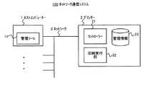
図1は、本発明を適用したネットワーク通信システムの実施の形態例に係る構成図である。図1に示すネットワーク通信システム100が本実施の形態例に係るシステムであり、ネットワーク3で接続される、SNMPマネージャとしての1以上のホストコンピューター1とSNMPエージェントとしてのプリンター2から構成される。当該システムでは、ホストコンピューター1とプリンター2間の通信において、SNMPv1に則った独自の拡張メッセージが用いられ、当該メッセージの拡張部分に含まれるホストコンピューター1の機器識別情報(機器ID)に基づいて、プリンター2の管理情報23に対する排他的なアクセス、すなわち、複数ユーザーの同時アクセスを許さない制御が実行される。また、当該拡張メッセージにおいては、実際のデータ部分は暗号化されるが、上記拡張部分に、認証のための情報及び暗号化の情報が含まれるので、受信側機器は、これらの情報に基づいて送信元の認証及び暗号化されたデータの復号が可能となり、SNMPv1において通信セキュリティの向上を図ることができる。 FIG. 1 is a configuration diagram according to an embodiment of a network communication system to which the present invention is applied. A
なお、図1では、複数のホストコンピューター1と1台のプリンター2が示されるが、ネットワーク3を介して接続されるプリンターは複数存在しても構わない。また、本実施の形態例では、SNMPv1を用いるが、SNMPv2cを用いてもよい。 In FIG. 1, a plurality of
ホストコンピューター1は、一般的なパーソナルコンピューター等で構成され、図示していないが、CPU、RAM、HDD、通信インターフェース、表示装置、操作装置等を備える。当該ホストコンピューター1は、プリンター2に印刷指示を行うプリンター2のホスト装置として機能するが、上述したように、SNMPマネージャとしてプリンター2の管理情報23にアクセスし、当該情報の取得及び設定を行う機能を有する。 The
当該機能を司るのが、図1に示す管理ツール11であり、プリンター2の管理者は当該ツールを使用して、プリンター2の設定値を変更したり、プリンター2のステータス情報を取得したりする。当該管理ツール11は、プリンター2に関する上記管理情報の取得、設定に係る処理を実行するためのプログラム、当該プログラムに従って処理を実行する上記CPU、処理中のデータを保持する上記RAM、当該プログラムが格納される上記HDD等で構成される。また、当該プログラムは、プリンター2のユーティリティソフトウェアとして、CDからインストールされる、あるいは、インターネット等を介して所定のサイトからダウンロードされる、ことにより備えられる。 The management tool 11 shown in FIG. 1 controls the function, and the administrator of the
また、ホストコンピューター1の上記HDDには、当該機器の識別情報である機器IDと、前述した認証及び暗号化のための認証/暗号化キーが記憶されている。機器IDは、SNMPの拡張メッセージを用いる場合の識別情報であり、予め決定されて記憶されている。また、認証/暗号化キーは、プリンター2側にも保持される共有キーであり、これも予め決定されて記憶されている。 The HDD of the
次に、プリンター2は、上記ホストコンピューター1からの印刷指示に従って印刷を実行する機器であり、図1に示すように、コントローラー21、印刷実行部22、管理情報23などを備える。また、上述の通り、SNMPエージェントとしてホストコンピューター1からのアクセスを受ける。 Next, the
コントローラー21は、機器全体を制御する部分であり、特に、上記印刷指示を受けた場合には、印刷データの処理、印刷実行部22への印刷指示等を実行する。また、管理情報23に対するホストコンピューター1からのアクセスに応答する処理も実行する。なお、コントローラー21は、CPU、RAM、ROM、NVRAM、ASIC、HDD等で構成され、上記アクセスに対する応答処理は、上記ROMに記憶されたプログラムと当該プログラムに従った上記CPUの動作によって実行される。 The
印刷実行部22は、コントローラー21の指示に従って印刷媒体に対して印刷処理を実行する部分である。 The print execution unit 22 is a part that executes print processing on a print medium in accordance with an instruction from the
次に、管理情報23は、プリンター2の各種管理情報であり、MIBとして上記HDDに格納される。管理情報23には、プリンター2の各種動作のための設定値(例えば、デフォルトの各印刷条件)やプリンター2の状態を示すステータス情報(例えば、各エラー情報)などが含まれ、上述したホストコンピューター1からのSNMPによるアクセスを受ける。 Next, the management information 23 is various management information of the
以上説明したような構成を有する本ネットワーク通信システム100では、上述のとおり、SNMPv1に則った拡張メッセージを用いて通信を行うことに特徴があり、以下、この拡張メッセージについて説明する。図2は、拡張メッセージの構造を説明するための図である。 As described above, the
図2の(a)は、SNMPv1によるメッセージ(図中のA)のデータ構造を示している。図示されるように、SNMPv1メッセージには、データユニット(PDU)の領域(図中のB)があり、その中にデータを格納するためのデータリストの領域(図中のC)がある。データリストの領域には、複数のデータが格納できる構造となっており、一つのデータを格納する領域(図中のD)は、識別子(OID)を格納する領域(図中のE)と値(Value)を格納する領域(図中のF)から構成されている。 FIG. 2A shows the data structure of a message (A in the figure) by SNMPv1. As shown in the figure, the SNMPv1 message has a data unit (PDU) area (B in the figure), and a data list area (C in the figure) for storing data therein. The data list area has a structure capable of storing a plurality of data, and an area for storing one data (D in the figure) is an area for storing an identifier (OID) (E in the figure) and a value. It is composed of an area (F in the figure) for storing (Value).
識別子(OID)は、アクセスするMIBオブジェクトの識別子であり、換言すれば、アクセス対象の管理情報を識別する情報である。また、値(Value)は、当該識別子で特定される管理情報の値である。これら識別子と値が対となって1つのデータを構成している。 The identifier (OID) is an identifier of the MIB object to be accessed, in other words, information for identifying the management information to be accessed. The value (Value) is a value of management information specified by the identifier. These identifiers and values are paired to constitute one data.
本実施の形態例における拡張メッセージは、このようなSNMPv1の標準構造に則った上で、上記値(Value)の領域に各種の情報を格納し、新たな機能を実現させるものである。図2の(b)は、拡張メッセージとしてSNMPv1メッセージを用いる場合の、上記値(Value)の領域におけるデータ構造を示している。 The extended message in the present embodiment is based on the standard structure of SNMPv1, and stores various information in the value (Value) area to realize a new function. FIG. 2B shows a data structure in the value (Value) area when an SNMPv1 message is used as the extended message.
図に示すように、拡張メッセージでは、上記値(Value)の領域(図中のF)が、付加情報の領域(図中のG)とデータリストの領域(図中のFC)から構成される。付加情報は、拡張メッセージで新たに実現する各機能のための情報であり、具体的には、排他的アクセスのための上述した機器ID、暗号化機能のための暗号化アルゴリズム種別及び暗号化パラメータ、認証機能のための認証コードなどの情報が含まれる。 As shown in the figure, in the extended message, the value (Value) area (F in the figure) is composed of an additional information area (G in the figure) and a data list area (FC in the figure). . The additional information is information for each function newly realized by the extended message, specifically, the above-described device ID for exclusive access, the encryption algorithm type for the encryption function, and the encryption parameter Information such as an authentication code for the authentication function is included.
暗号化アルゴリズム種別は、暗号化の手法を特定する情報であり、暗号化パラメータは、暗号化手法によっては必要となるパラメータの情報である。また、認証コードは、アクセス先で認証を得るために送信側で生成するコードであり、付加情報の領域内に収められる(図中のH)。 The encryption algorithm type is information that specifies an encryption method, and the encryption parameter is parameter information that is necessary depending on the encryption method. The authentication code is a code generated on the transmission side to obtain authentication at the access destination, and is stored in the additional information area (H in the figure).
これらの付加情報は、受信側の機器で解釈され、各機能を実現するために用いられる。 These additional information is interpreted by the receiving device and used to implement each function.
次に、データリストの領域(図中のFC)には、上述したSNMPv1の標準構造におけるデータリストの領域(図中のC)の情報が格納され、従って、図に示すように、識別子領域(図中のFE)及び値領域(図中のFF)からなるデータ領域(図中のFD)が1以上格納される。これらデータ領域には、上述した標準構造の場合と同様の情報が格納される。 Next, in the data list area (FC in the figure), information on the data list area (C in the figure) in the SNMPv1 standard structure described above is stored. Therefore, as shown in the figure, the identifier area ( One or more data areas (FD in the figure) consisting of FE in the figure and value areas (FF in the figure) are stored. In these data areas, the same information as in the case of the standard structure described above is stored.
このように、拡張メッセージでは、SNMPv1メッセージの値(Value)領域に、データユニット(PDU)に収められる情報がカプセル化された構造となっている。また、この拡張メッセージを使用する場合には、カプセル化された情報を収める値(Value)領域と対をなす識別子(OID)領域(図中のE)に、当該拡張メッセージであることを示す情報(拡張メッセージ用の識別子)が格納される。当該拡張メッセージ用の識別子は、そのメッセージに付加情報が含まれることを示す情報でもある。 Thus, the extended message has a structure in which the information stored in the data unit (PDU) is encapsulated in the value (Value) area of the SNMPv1 message. When this extended message is used, information indicating that the message is the extended message in an identifier (OID) area (E in the figure) that is paired with a value (Value) area for storing the encapsulated information. (Identifier for extended message) is stored. The identifier for the extended message is information indicating that additional information is included in the message.
以上説明したような構造を有する拡張メッセージが、本実施の形態例におけるネットワーク通信システム100では用いられ、ホストコンピューター1の管理ツール11及びプリンター2のコントローラー21の双方で拡張メッセージの生成及び解釈がなされる。 The extended message having the structure as described above is used in the
次に、当該拡張メッセージを用いた通信処理の具体的な処理手順について説明する。まず、ホストコンピューター1からプリンター2の管理情報23へログインする際の処理について説明する。図3は、ログイン時の処理手順を例示したフローチャートである。図3の(a)は、ホストコンピューター1側の処理を示している。まず、プリンター2の管理情報23にアクセスをしたいプリンター2の管理者等が管理ツール11に対してログインを要求する操作を行うと、管理ツール11は、ログイン用拡張メッセージの生成を実行する(ステップS10)。 Next, a specific processing procedure of communication processing using the extended message will be described. First, processing when logging in to the management information 23 of the
当該処理の具体的な処理手順は図3の(b)に示され、まず、ログイン要求データを生成する(ステップS11)。具体的には、図2に示したFEとFFの領域に格納する、ログインを要求する情報を生成する。識別子領域FEに対しては、ログイン又はログアウトの要求であることを示す識別情報が生成され、値領域FFに対しては、ログインである旨を示す情報が生成される。 A specific processing procedure of the processing is shown in FIG. 3B. First, login request data is generated (step S11). Specifically, information for requesting login stored in the FE and FF areas shown in FIG. 2 is generated. Identification information indicating a login or logout request is generated for the identifier area FE, and information indicating login is generated for the value area FF.
図4は、送受信される拡張メッセージの生成過程及び受信後の処理過程を示す図である。図4の(a)は、拡張メッセージの生成過程を示しており、上記生成したログイン要求データは、当該図においては送信データ(a−1)に相当する。 FIG. 4 is a diagram illustrating a process of generating an extended message to be transmitted and received and a process after reception. FIG. 4A shows an extended message generation process, and the generated login request data corresponds to transmission data (a-1) in the figure.
図3に戻って、次に、管理ツール11は、生成したログイン要求データ(送信データ)の暗号化処理を行う(ステップS12)。当該暗号化処理では、所定の暗号化手法に従って、前述した認証/暗号化キーを用いてログイン要求データを暗号化し、使用した暗号化アルゴリズムの種別の情報を付加情報とする。また、暗号化パラメータを必要とする手法を用いた場合には、その暗号化パラメータも付加情報として付加する(ステップS13)。 Returning to FIG. 3, next, the management tool 11 performs encryption processing of the generated login request data (transmission data) (step S12). In the encryption process, the login request data is encrypted using the authentication / encryption key described above according to a predetermined encryption method, and information on the type of encryption algorithm used is used as additional information. If a method that requires an encryption parameter is used, the encryption parameter is also added as additional information (step S13).
図4では、ホストコンピューター1が保持する前述した認証/暗号化キー(a−2)が暗号化に使用され、送信データ(a−1)が暗号化された送信データ(a−3)になる。また、付加情報(a−4)に暗号化アルゴリズム種別及び必要に応じて暗号化パラメータが付与される。 In FIG. 4, the above-described authentication / encryption key (a-2) held by the
なお、暗号化手法としては、従前の各種方法を用いることができ、予め定められた幾つかの手法の中から、管理ツールの操作者の指示あるいは所定のルールに従って、使用する手法を決定する。 Various conventional methods can be used as an encryption method, and a method to be used is determined from among predetermined methods according to an instruction of an operator of the management tool or a predetermined rule.
次に、管理ツール11は、機器IDを付加情報として付与する(ステップS14)。前述のように、ホストコンピューター1には当該機器の機器IDが保持されているのでその情報を読み出して付与する。図4では、付加情報(a−4)に付与される。また、認証アルゴリズム種別も付加情報として付与される。 Next, the management tool 11 gives the device ID as additional information (step S14). As described above, since the device ID of the device is held in the
その後、管理ツール11は、認証コードを生成して付加情報とする(ステップS15)。認証コードは、図4に示されるように、生成された付加情報(a−4)及び暗号化された送信データ(a−3)と、上記認証/暗号化キー(a−2)を用いて上記認証アルゴリズム種別に示される方法で生成する。なお、認証コードが生成される前の時点においては、認証コードが格納される領域には全て0の値が入れられる。 Thereafter, the management tool 11 generates an authentication code as additional information (step S15). As shown in FIG. 4, the authentication code uses the generated additional information (a-4) and encrypted transmission data (a-3) and the authentication / encryption key (a-2). It is generated by the method shown in the authentication algorithm type. Note that, at the time before the authentication code is generated, a value of 0 is entered in the area where the authentication code is stored.
認証コードを生成する手法には各種の方法を用いることができるが、例えば、上記生成に使用するデータのハッシュ値を用いる方法を取ることができる。そして、この生成手法は、予め定められた幾つかの手法の中から、管理ツールの操作者の指示あるいは所定のルールに従って、使用する手法を決定し、その認証アルゴリズム種別が上述のとおり付加情報とされる。 Various methods can be used for generating the authentication code. For example, a method using a hash value of data used for the generation can be used. This generation method determines a method to be used in accordance with an instruction from an operator of the management tool or a predetermined rule from among a plurality of predetermined methods, and the authentication algorithm type is the additional information as described above. Is done.
このようにして生成された認証コード(a−5)は、図4に示すように、認証コードの領域(図2のH)の情報として、これまで生成した付加情報に付与される(a−6)。換言すれば、上記全て0の値が生成した認証コードに置き換わる。 As shown in FIG. 4, the authentication code (a-5) generated in this way is added to the additional information generated so far as information of the authentication code area (H in FIG. 2) (a−). 6). In other words, the value of all 0 is replaced with the generated authentication code.
以上の処理で、ログイン用拡張メッセージの拡張部分が生成されるので、管理ツール11は、生成した付加情報と暗号化された送信データを、SNMPv1メッセージの値(Value)領域(図2のF)に格納すると共に、上述した拡張メッセージ用識別子を識別子(OID)領域(図2のE)に格納し、SNMPv1メッセージを完成させる。すなわち、上記生成した拡張部分をSNMPメッセージにカプセル化する(ステップS16)。 With the above processing, an extended portion of the login extended message is generated. Therefore, the management tool 11 uses the generated additional information and the encrypted transmission data as the SNMPv1 message value (Value) area (F in FIG. 2). And the above-mentioned extended message identifier is stored in the identifier (OID) area (E in FIG. 2) to complete the SNMPv1 message. That is, the generated extension part is encapsulated in an SNMP message (step S16).
図4では、これまでに生成した情報が値(Value)領域(a−7)に格納され、拡張メッセージ用識別子が識別子(OID)領域(a−8)に格納される。 In FIG. 4, the information generated so far is stored in the value (Value) area (a-7), and the identifier for the extended message is stored in the identifier (OID) area (a-8).
このようにして、ログイン用拡張メッセージがSNMPv1メッセージとして生成されると、管理ツール11は、当該メッセージをプリンター2へ送信する(ステップS20)。 When the login extended message is generated as the SNMPv1 message in this way, the management tool 11 transmits the message to the printer 2 (step S20).
図3の(c)は、当該メッセージを受信するプリンター2側の処理手順を示しており、また、図4の(b)は、その受信したメッセージに対する処理過程を示している。プリンター2のコントローラー21は、上記送信されたログイン用拡張メッセージを受信し(ステップS30)、その識別子(OID)領域に格納されている拡張メッセージ用識別子から当該メッセージが拡張メッセージであると判断し、まず、この時点で、管理情報23に他の機器がログイン中であるか否かを確認する(ステップS40)。 FIG. 3C shows a processing procedure on the
プリンター2では、前述した管理情報23への同時アクセスによる問題を防ぐために、管理情報23へ同時にアクセスすることのできる機器数(ユーザー数)を、一例として1に制限する仕様としている。すなわち、他の機器が管理情報23にログイン中(アクセス中)である場合には、ログイン、アクセスを許さない仕様としている。 In the
後述するように、プリンター2では、ログインを許可した際に、ログインしたホストコンピューター1の機器IDを上記RAMに保持するようにしているため、上記確認(S40)では、その保持した機器IDと今回受信したメッセージの付加情報に含まれる機器IDを比較し(図4では(b−1))、双方が異なっていれば、他の機器がログイン中であると判断する。一方、双方が同じである、又は、RAMに機器IDを保持していない場合には、他の機器がログイン中ではないと判断する。 As will be described later, in the
当該確認の結果、他の機器がログイン中であると判断した場合には(ステップS40のYes)、コントローラー21は、当該受信したメッセージによる要求を受け付けず、すなわち、アクセスを許可せず、その旨のエラー応答を送信元のホストコンピューター1に行って(ステップS100)、当該ログイン処理を終了する。なお、当該応答メッセージも拡張メッセージによって行われる。 As a result of the confirmation, if it is determined that another device is logged in (Yes in step S40), the
一方、他の機器がログイン中ではないと判断した場合には(ステップS40のNo)、コントローラー21は、認証の処理を行う(ステップS50)。当該認証の処理では、図4に示されるように、まず、受信したメッセージの付加情報に含まれる認証コードを取り出して保持する(b−2)。その後、認証コードが格納されていた領域の値を全て0にした拡張部分、すなわち、付加情報と暗号化された送信データ(b−6)と、プリンター2が保持していた認証/暗号化キー(b−4)を用いて、当該付加情報に含まれる認証アルゴリズム種別が示す方法で、認証コードを生成する(b−5)。そして、生成した認証コード(b−5)と上記保持した認証コード(b−2)を比較し、一致すれば認証成功と判断し、一致しなければ認証失敗と判断する。 On the other hand, if it is determined that no other device is logged in (No in step S40), the
認証が失敗した場合には(ステップS50の失敗)、送信先が保持する認証/暗号化キーが正しくないものである、又は、送信されたデータが通信途中で改竄された、虞があるため、コントローラー21は、当該メッセージを受け付けず、エラー応答を送信元のホストコンピューター1に行って(ステップS100)、当該ログイン処理を終了する。 If the authentication fails (failure in step S50), the authentication / encryption key held by the transmission destination may be incorrect, or the transmitted data may be altered during communication. The
一方、認証が成功した場合には(ステップS50の成功)、当該メッセージが正しい送信先から送られ、通信途中でデータの改竄もされていないと判断して、コントローラー21は、当該メッセージを受け付けて応答処理をすべく、暗号化された部分の復号処理を行う(ステップS60)。当該復号処理では、図4に示すように、暗号化された送信データ(b−6)を、プリンター2が保持していた認証/暗号化キー(b−4)を用いて、付加情報に含まれる暗号化アルゴリズム種別が示す方法で、必要に応じて付加情報に含まれる暗号化パラメータを用いて、復号し、元の送信データ(b−7)を生成する。 On the other hand, if the authentication is successful (success in step S50), the
その後、コントローラー21は、復号された送信データを解釈し、この場合には、上記ホストコンピューター1により生成されたログイン要求データを解釈し、ログインが要求されていると判断する。ここでは、上記S40の判断で、他の機器がログインしていないので、当該ログイン要求を受け付け、管理情報23へのログインを許可し、当該メッセージの付加情報に含まれる機器IDをログイン中の機器を特定する情報として上記RAMに記憶する(ステップS70)。当該記憶された機器IDが上述したS40の判断に用いられる。 Thereafter, the
次に、コントローラー21は、当該許可したログインのログインセッションを開始し(ステップS80)、ログインが成功した旨の応答を送信元のホストコンピューター1に行って(ステップS90)、当該ログイン処理を終了する。なお、当該応答メッセージも拡張メッセージによって行われる。 Next, the
次に、ログインセッション中における通信処理について説明する。図5は、ログインセッション中における通信処理の手順を例示したフローチャートである。ここでは、ホストコンピューター1がプリンター2の管理情報23にアクセスしその情報を取得したり設定したりするためのメッセージが、拡張メッセージとしてホストコンピューター1からプリンター2へ送信され、プリンター2ではその拡張メッセージを受信し、受信したメッセージに対する処理が実行される。 Next, communication processing during a login session will be described. FIG. 5 is a flowchart illustrating a communication processing procedure during a login session. Here, a message for the
図5の(a)及び(b)は、ホストコンピューター1側の処理を示しており、まず、管理ツール11は、送信するデータを拡張メッセージとして生成する(ステップ110)。具体的には、前述したログイン用拡張メッセージの生成の場合と同様に(図3のS11−S16)、送信データの生成、暗号化、暗号化パラメータの付与、機器IDの付与、認証コードの生成、付与、及びSNMPメッセージへのカプセル化(ステップS111−S116)を実行する。なお、送信データは、ここでは、ログイン要求データではないので、アクセスする内容に応じた、アクセス対象の識別子とその値が格納される。 5A and 5B show processing on the
図5の(c)は、プリンター2側の処理を示しており、コントローラー21は、上記拡張メッセージを受信して(ステップS130)、その識別子(OID)領域に格納されている拡張メッセージ用識別子から当該メッセージが拡張メッセージであると判断する。その後、コントローラー21は、機器IDの確認を行う(ステップS140)。当該確認は、ログイン用拡張メッセージの場合のステップS40と同様の処理であり、送信された機器IDとプリンター2に保持されている機器IDが不一致の場合には(ステップS140の不一致)、複数機器の同時アクセスを認めないので、コントローラー21は、当該メッセージを受け付けず、エラー処理を実行して(ステップS180)当該通信処理を終了する。具体的には、図3のステップS100の場合と同様のエラー応答が行われる。 FIG. 5C shows processing on the
一方、送信された機器IDとプリンター2に保持されている機器IDが一致した場合には(ステップS140の一致)、ログイン用拡張メッセージの場合と同様に(図3のS50及びS60)、コントローラー21は、認証及び復号の処理を実行する(ステップS150及びS160)。認証に失敗した場合には(ステップS150の失敗)、当該メッセージを受け付けず、エラー処理を実行して(ステップS180)当該通信処理を終了する。具体的には、図3のステップS100の場合と同様のエラー応答が行われる。 On the other hand, if the transmitted device ID matches the device ID held in the printer 2 (match in step S140), as in the case of the login extended message (S50 and S60 in FIG. 3), the
復号処理の後は、コントローラー21は、復号した送信データの内容を解釈し、その要求に応じたデータ処理を実行する(ステップS170)。例えば、送信データの内容が、所定の管理情報の値を取得することを要求するものであれば、その値を返答する拡張メッセージを生成して、送信元のホストコンピューター1に返信する。 After the decryption process, the
このようにして、データ処理が実行されると当該通信処理が終了する。 In this way, when the data processing is executed, the communication processing ends.
なお、ログアウトは、ログイン中のホストコンピューター1から、ログイン用拡張メッセージの場合と同様に、ログアウトを要求する拡張メッセージをプリンター2に送信することによって実行される。また、当該ログアウトの要求メッセージが受信されなくても、プリンター2側で、時間によりログアウトを実行するようにしても良い。そして、ログアウトが実行された場合には、上述のRAMに記憶する機器IDを削除する。 Logout is executed by transmitting an extended message requesting logout from the logged-in
なお、以上説明した例では、ログイン可能な機器数(可能なログインセッション数、同時アクセス可能な機器数)を1としたが、同時アクセスによる弊害が抑えられる範囲で、2以上としてもよい。この場合には、プリンター2側で、ログイン中(アクセス中)の全ての機器IDを保持し、新たな拡張メッセージを受信する度に、ログインセッション数が定められた数を超えないように、アクセスの許可/不許可を判断する。 In the example described above, the number of devices that can be logged in (the number of possible login sessions and the number of devices that can be accessed simultaneously) is 1. However, it may be 2 or more as long as adverse effects due to simultaneous access are suppressed. In this case, on the
また、以上の例では、排他的アクセスに機器IDを用いたが、上述した管理者等のユーザーIDを用いることもできる。これにより、ログイン可能なユーザー数を制限することができる。この場合には、拡張メッセージの付加情報に、機器IDに換わってユーザーIDが付与される。 In the above example, the device ID is used for exclusive access, but the above-described user ID such as an administrator can also be used. Thereby, the number of users who can log in can be limited. In this case, a user ID is assigned to the additional information of the extended message instead of the device ID.
また、以上の例では、ホストコンピューター1がSNMPマネージャであり、プリンター2がSNMPエージェントであったが、1つの機器、例えば、自らの管理情報(MIB)を有するコンピューターが、SNMPマネージャとして他の機器の管理情報にアクセスすると共に、SNMPエージェントとして他の機器から管理情報に対するアクセスを受ける、という場合も想定され、このような場合にも、拡張メッセージを用いることができる。この場合、上記の説明で、ホストコンピューター1が実行する処理とプリンター2が実行する処理の両方を、一つの機器で実行することが可能になる。 In the above example, the
以上説明したように、本実施の形態例におけるネットワーク通信システム100では、SNMPv1に則った拡張メッセージを使用し、その拡張部分にアクセス元の識別情報を含めることで、比較的簡便な処理で、管理情報に対する排他的なアクセスが可能になり、同時アクセスによる問題を解消することができる。 As described above, in the
また、上記拡張部分に認証のための情報が付与されて、認証機能が実現されるため、SNMPv1において、もなりすましなどのセキュリティ上の問題を解決することができる。 In addition, since authentication information is provided by providing authentication information to the extended portion, a security problem such as spoofing can be solved in SNMPv1.
さらに、上記認証のために生成される認証コードには、送信するデータ自体が用いられ、通信途中のデータの改竄による問題も解消することができる。 Furthermore, the data itself to be transmitted is used for the authentication code generated for the authentication, and the problem caused by falsification of data during communication can be solved.
また、上記拡張部分に暗号化情報を付与し、送信データを暗号化するので、暗号化機能が実現され、SNMPv1において、盗聴などの弊害を抑えることができる。 In addition, since the encrypted information is added to the extended portion and the transmission data is encrypted, an encryption function is realized, and it is possible to suppress harmful effects such as eavesdropping in SNMPv1.
なお、上記実施の形態例では、SNMPエージェントがプリンターであったが、管理情報(MIB)を備える通信可能な機器であれば本発明を適用することができる。 In the above embodiment, the SNMP agent is a printer, but the present invention can be applied to any communicable device having management information (MIB).
本発明の保護範囲は、上記の実施の形態に限定されず、特許請求の範囲に記載された発明とその均等物に及ぶものである。 The protection scope of the present invention is not limited to the above-described embodiment, but covers the invention described in the claims and equivalents thereof.
1 ホストコンピューター、 2 プリンター、 3 ネットワーク、 11 管理ツール、 21 コントローラー、 22 印刷実行部、 23 管理情報 1 host computer, 2 printer, 3 network, 11 management tool, 21 controller, 22 print execution unit, 23 management information
Claims (10)
Translated fromJapanese第一機器が第二機器の備える管理情報にアクセスする場合に、
前記第一機器が、アクセス対象の識別情報を格納するための識別子領域と当該アクセス対象の値を格納するための値領域から成るデータ領域の、前記値領域に、前記アクセス対象の値とは別に、少なくとも、当該第一機器の機器識別情報又は当該第一機器のユーザーの識別情報を含む付加情報を加えた、アクセス要求メッセージを生成し、当該生成したメッセージを前記第二機器へ送信する工程と、
前記第二機器が、前記送信されたメッセージに含まれる前記機器識別情報又は前記ユーザーの識別情報と、その時点で前記管理情報にアクセス中の機器又はユーザーの情報に基づいて、アクセス中の機器又はユーザーの数が所定数を超えないように、前記送信されたメッセージによって要求されるアクセスの許可/不許可を決定する工程と、を有する
ことを特徴とするネットワーク通信方法。A network communication method using a simple network management protocol between devices connected via a network,
When the first device accesses the management information of the second device,
The first device has a data area consisting of an identifier area for storing identification information to be accessed and a value area for storing the value to be accessed, in the value areaseparately from the value to be accessed. atleast the and the additional information added containing device identification information or user identification information of the first device of the first device, generating an access request message, and transmitting the message thus generated to the second device ,
Based on the device identification information or the user identification information included in the transmitted message, and the device or user information accessing the management information at that time, the second device is accessing the device or Determining whether to permit / deny access requested by the transmitted message so that the number of users does not exceed a predetermined number.
前記第一機器が送信するアクセス要求メッセージの、前記識別子領域には、当該メッセージに前記付加情報が含まれることを示す情報が格納され、前記値領域には、前記アクセス対象の識別情報とその値が格納される
ことを特徴とするネットワーク通信方法。In claim 1,
Information indicating that the additional information is included in the message is stored in the identifier area of the access request message transmitted by the first device, and the identification information of the access target and its value are stored in the value area. A network communication method characterized in that is stored.
前記アクセスの許可/不許可を決定する際の前記所定数が1である
ことを特徴とするネットワーク通信方法。In claim 1 or claim 2,
The network communication method, wherein the predetermined number when determining whether to permit or not permit the access is 1.
前記第二機器は、前記アクセスの許可を決定した場合に、前記送信されたメッセージに含まれる前記機器識別情報又は前記ユーザーの識別情報を、前記アクセス中の機器又はユーザーの情報として記憶する
ことを特徴とするネットワーク通信方法。In any one of Claim 1 thru | or 3,
When the second device determines permission to access, the second device stores the device identification information or the user identification information included in the transmitted message as the information on the device or user being accessed. A network communication method.
前記第一機器が送信するアクセス要求メッセージの前記付加情報には、送信元を認証するための情報が含まれ、
前記第二機器は、当該認証をするための情報に基づいて認証処理を実行する
ことを特徴とするネットワーク通信方法。In any one of Claims 1 thru | or 4,
The additional information of the access request message transmitted by the first device includes information for authenticating the transmission source,
The network communication method, wherein the second device executes an authentication process based on information for performing the authentication.
前記認証をするための情報には、前記送信されたメッセージに基づいて生成されたコードが含まれる
ことを特徴とするネットワーク通信方法。In claim 5,
The information for performing authentication includes a code generated based on the transmitted message. A network communication method, wherein:
前記第一機器が送信するアクセス要求メッセージにおける、前記アクセス対象の識別情報とその値についてのデータが暗号化され、当該暗号化に関する情報が当該メッセージの前記付加情報に含まれ、
前記第二機器は、当該暗号化に関する情報に基づいて、前記暗号化されたデータを復号する
ことを特徴とするネットワーク通信方法。In any one of Claims 2 thru | or 6,
In the access request message transmitted by the first device, the access target identification information and its value data are encrypted, and information related to the encryption is included in the additional information of the message,
The network communication method, wherein the second device decrypts the encrypted data based on information related to the encryption.
前記第一機器が前記第二機器の備える管理情報にアクセスする場合に、
前記第一機器は、アクセス対象の識別情報を格納するための識別子領域と当該アクセス対象の値を格納するための値領域から成るデータ領域の、前記値領域に、前記アクセス対象の値とは別に、少なくとも、当該第一機器の機器識別情報又は当該第一機器のユーザーの識別情報を含む付加情報を加えた、アクセス要求メッセージを生成し、当該生成したメッセージを前記第二機器へ送信し、
前記第二機器は、前記送信されたメッセージに含まれる前記機器識別情報又は前記ユーザーの識別情報と、その時点で前記管理情報にアクセス中の機器又はユーザーの情報に基づいて、アクセス中の機器又はユーザーの数が所定数を超えないように、前記送信されたメッセージによって要求されるアクセスの許可/不許可を決定する
ことを特徴とするネットワーク通信システム。A network communication system comprising one or more first devices and a second device that communicates with the first device using a simple network management protocol via a network,
When the first device accesses management information of the second device,
The first device has a data area consisting of an identifier area for storing identification information to be accessed and a value area for storing the value to be accessed, in the value areaseparately from the value to be accessed. , At least add the additional information including the device identification information of the first device or the user identification information of the first device, generate an access request message, and transmit the generated message to the second device,
Based on the device identification information or the user identification information included in the transmitted message and the device or user information accessing the management information at that time, the second device A network communication system, wherein access permission / denial requested by the transmitted message is determined so that the number of users does not exceed a predetermined number.
前記他の機器が備える管理情報にアクセスする場合に、
アクセス対象の識別情報を格納するための識別子領域と当該アクセス対象の値を格納するための値領域から成るデータ領域の、前記値領域に、前記アクセス対象の値とは別に、少なくとも、当該ネットワーク通信装置の機器識別情報又は当該装置のユーザーの識別情報を含む付加情報を加えた、アクセス要求メッセージを生成し、当該生成したメッセージを前記他の機器へ送信し、
前記他の機器から前記アクセス要求メッセージと同様のメッセージを受信した場合に、
前記受信したメッセージに含まれる前記他の機器の前記機器識別情報又は前記他の機器の前記ユーザーの識別情報と、その時点で当該ネットワーク通信装置が備える管理情報にアクセス中の機器又はユーザーの情報に基づいて、アクセス中の機器又はユーザーの数が所定数を超えないように、前記受信したメッセージによって要求されるアクセスの許可/不許可を決定する
ことを特徴とするネットワーク通信装置。A network communication device that communicates with other devices connected via a network using a simple network management protocol,
When accessing the management information provided in the other device,
In the data area consisting of an identifier area for storing identification information of an access target and a value area for storing the value of theaccess target, at least the network communication in the value areaapart from the value of the access target Generating an access request message including additional information including device identification information of the device or user identification information of the device, and transmitting the generated message to the other device;
When a message similar to the access request message is received from the other device,
The device identification information of the other device or the user identification information of the other device included in the received message and the information of the device or user currently accessing the management information included in the network communication device at that time Based on the above, the network communication apparatus determines permission / non-permission of access requested by the received message so that the number of accessing devices or users does not exceed a predetermined number.
前記他の機器が備える管理情報にアクセスする場合に、
アクセス対象の識別情報を格納するための識別子領域と当該アクセス対象の値を格納するための値領域から成るデータ領域の、前記値領域に、前記アクセス対象の値とは別に、少なくとも、当該ネットワーク通信装置の機器識別情報又は当該装置のユーザーの識別情報を含む付加情報を加えた、アクセス要求メッセージを生成し、当該生成したメッセージを前記他の機器へ送信する工程を、前記ネットワーク通信装置に実行させ、
前記他の機器から前記アクセス要求メッセージと同様のメッセージを受信した場合に、
前記受信したメッセージに含まれる前記他の機器の前記機器識別情報又は前記他の機器の前記ユーザーの識別情報と、その時点で当該ネットワーク通信装置が備える管理情報にアクセス中の機器又はユーザーの情報に基づいて、アクセス中の機器又はユーザーの数が所定数を超えないように、前記受信したメッセージによって要求されるアクセスの許可/不許可を決定する工程を、前記ネットワーク通信装置に実行させる
ことを特徴とするプログラム。A program that causes a network communication device that communicates with other devices connected via a network using a simple network management protocol to execute communication processing,
When accessing the management information provided in the other device,
In the data area consisting of an identifier area for storing identification information of an access target and a value area for storing the value of theaccess target, at least the network communication in the value areaapart from the value of the access target Causing the network communication device to execute a step of generating an access request message including additional information including device identification information of the device or user identification information of the device, and transmitting the generated message to the other device. ,
When a message similar to the access request message is received from the other device,
The device identification information of the other device or the user identification information of the other device included in the received message and the information of the device or user currently accessing the management information included in the network communication device at that time Based on the above, the network communication apparatus is caused to execute the step of determining permission / denial of access required by the received message so that the number of devices or users being accessed does not exceed a predetermined number. Program.
Priority Applications (3)
| Application Number | Priority Date | Filing Date | Title |
|---|---|---|---|
| JP2010289338AJP5716390B2 (en) | 2010-12-27 | 2010-12-27 | Network communication method, network communication system, network communication device, and program thereof |
| US13/330,777US9300546B2 (en) | 2010-12-27 | 2011-12-20 | Network communication method, network communication system, network communication apparatus and program using SNMP with improved security |
| CN201110439546.3ACN102546240B (en) | 2010-12-27 | 2011-12-23 | Network communication method, network communicating system and network communication device |
Applications Claiming Priority (1)
| Application Number | Priority Date | Filing Date | Title |
|---|---|---|---|
| JP2010289338AJP5716390B2 (en) | 2010-12-27 | 2010-12-27 | Network communication method, network communication system, network communication device, and program thereof |
Publications (2)
| Publication Number | Publication Date |
|---|---|
| JP2012137911A JP2012137911A (en) | 2012-07-19 |
| JP5716390B2true JP5716390B2 (en) | 2015-05-13 |
Family
ID=46318394
Family Applications (1)
| Application Number | Title | Priority Date | Filing Date |
|---|---|---|---|
| JP2010289338AActiveJP5716390B2 (en) | 2010-12-27 | 2010-12-27 | Network communication method, network communication system, network communication device, and program thereof |
Country Status (3)
| Country | Link |
|---|---|
| US (1) | US9300546B2 (en) |
| JP (1) | JP5716390B2 (en) |
| CN (1) | CN102546240B (en) |
Families Citing this family (7)
| Publication number | Priority date | Publication date | Assignee | Title |
|---|---|---|---|---|
| US10389601B2 (en)* | 2015-03-03 | 2019-08-20 | Comcast Cable Communications, Llc | Dynamic adaptive network |
| CN105071993B (en)* | 2015-08-26 | 2019-03-26 | 广州视睿电子科技有限公司 | Encryption state detection method and system |
| CN107222326B (en) | 2016-03-22 | 2021-02-02 | 斑马智行网络(香港)有限公司 | Access method, configuration method and apparatus for inter-device service |
| US20180089044A1 (en)* | 2016-09-27 | 2018-03-29 | Francesc Guim Bernat | Technologies for providing network interface support for remote memory and storage failover protection |
| US10969846B2 (en) | 2017-05-25 | 2021-04-06 | Virtual Power Systems, Inc. | Secure communication initiation and execution for datacenter power control |
| CN111191297B (en)* | 2019-12-31 | 2023-03-10 | 珠海奔图电子有限公司 | Security management information acquisition method, image forming apparatus, and storage medium |
| JP2024018410A (en)* | 2022-07-29 | 2024-02-08 | ブラザー工業株式会社 | Computer programs for communication devices and terminal devices |
Family Cites Families (21)
| Publication number | Priority date | Publication date | Assignee | Title |
|---|---|---|---|---|
| JP3492184B2 (en)* | 1997-02-03 | 2004-02-03 | キヤノン株式会社 | Network device control method and apparatus, and storage medium storing program for executing the control method |
| US7274474B2 (en)* | 1997-10-27 | 2007-09-25 | Canon Kabushiki Kaisha | Printing data held on a WWW server |
| US6788315B1 (en)* | 1997-11-17 | 2004-09-07 | Fujitsu Limited | Platform independent computer network manager |
| JP2000181829A (en)* | 1998-12-18 | 2000-06-30 | Canon Inc | Network device management system and method |
| US7698396B2 (en)* | 2000-01-31 | 2010-04-13 | Hitachi Software Engineering Co., Ltd. | Method of automatically recognizing network configuration including intelligent packet relay equipment, method of displaying network configuration chart, and system thereof |
| US7526480B2 (en)* | 2001-06-08 | 2009-04-28 | Cisco Technology, Inc. | Method and apparatus for controlled access of requests from virtual private network devices to managed information objects using simple network management protocol and multi-topology routing |
| JP2003271476A (en)* | 2002-03-15 | 2003-09-26 | Matsushita Electric Ind Co Ltd | SNMP network management system |
| US20030210699A1 (en)* | 2002-05-08 | 2003-11-13 | Adc Dsl Systems, Inc. | Extending a network management protocol to network nodes without IP address allocations |
| US7752301B1 (en)* | 2003-01-23 | 2010-07-06 | Gomez Acquisition Corporation | System and interface for monitoring information technology assets |
| EP1627493A1 (en)* | 2003-05-29 | 2006-02-22 | Telecom Italia S.p.A. | Method, system and computer program for the secured management of network devices |
| JP4527434B2 (en)* | 2004-04-16 | 2010-08-18 | 大日本印刷株式会社 | Portable information storage medium and program thereof |
| KR100714681B1 (en)* | 2004-11-05 | 2007-05-07 | 삼성전자주식회사 | Network management device and method |
| JP4405933B2 (en)* | 2005-03-18 | 2010-01-27 | キヤノン株式会社 | Control device, communication control method, communication control program, and storage medium |
| JP4550704B2 (en)* | 2005-09-20 | 2010-09-22 | 株式会社日立製作所 | Communication system and communication management method |
| JP2007188298A (en)* | 2006-01-13 | 2007-07-26 | Murata Mach Ltd | Snmp agent apparatus |
| US7877469B2 (en) | 2006-02-01 | 2011-01-25 | Samsung Electronics Co., Ltd. | Authentication and authorization for simple network management protocol (SNMP) |
| WO2008085203A2 (en)* | 2006-12-29 | 2008-07-17 | Prodea Systems, Inc. | Presence status notification from digital endpoint devices through a multi-services gateway device at the user premises |
| US7702803B2 (en)* | 2007-02-24 | 2010-04-20 | Wipro Limited | Security enhancement for SNMPv2c protocol |
| CN100484039C (en)* | 2007-03-22 | 2009-04-29 | 华为技术有限公司 | Network management apparatus and network management method |
| JP2009245075A (en) | 2008-03-31 | 2009-10-22 | Brother Ind Ltd | Data-providing system and communication device |
| US9298834B2 (en)* | 2009-05-26 | 2016-03-29 | Adobe Systems Incorporated | User presence data for web-based document collaboration |
- 2010
- 2010-12-27JPJP2010289338Apatent/JP5716390B2/enactiveActive
- 2011
- 2011-12-20USUS13/330,777patent/US9300546B2/enactiveActive
- 2011-12-23CNCN201110439546.3Apatent/CN102546240B/enactiveActive
Also Published As
| Publication number | Publication date |
|---|---|
| US9300546B2 (en) | 2016-03-29 |
| CN102546240B (en) | 2016-04-27 |
| US20120166608A1 (en) | 2012-06-28 |
| JP2012137911A (en) | 2012-07-19 |
| CN102546240A (en) | 2012-07-04 |
Similar Documents
| Publication | Publication Date | Title |
|---|---|---|
| US12309262B2 (en) | System and method for pre-shared key (PSK) based document security | |
| JP5716390B2 (en) | Network communication method, network communication system, network communication device, and program thereof | |
| US7533407B2 (en) | System and methods for providing network quarantine | |
| US11233790B2 (en) | Network-based NT LAN manager (NTLM) relay attack detection and prevention | |
| US7321971B2 (en) | System and method for secure remote access | |
| CN107122674B (en) | Access method of oracle database applied to operation and maintenance auditing system | |
| US20090031399A1 (en) | Method and Apparatus for Content Based Authentication for Network Access | |
| IL158309A (en) | Centralized network control | |
| JP2010526507A (en) | Secure communication method and system | |
| JP2009538478A5 (en) | ||
| JP2004288169A (en) | Network connection system | |
| JP2024507751A (en) | METHODS AND DEVICES FOR PROVIDING SECURITY LEVELS FOR COMMUNICATIONS | |
| US20150281211A1 (en) | Network security | |
| US20050097314A1 (en) | Communication apparatus, communication system, communication apparatus control method and implementation program thereof | |
| JP4455965B2 (en) | Authority information generating method, communication apparatus, program, and recording medium | |
| CN104753886A (en) | Locking method for remote user, unlocking method and device | |
| CN119227051A (en) | Device access method, product, device and medium | |
| JP4775154B2 (en) | COMMUNICATION SYSTEM, TERMINAL DEVICE, PROGRAM, AND COMMUNICATION METHOD | |
| JP6035864B2 (en) | Image forming system, image forming apparatus, authentication server, client PC, image forming apparatus control method, and program | |
| JP2006260027A (en) | Quarantine system and quarantine method using VPN and firewall | |
| KR20060044494A (en) | Network management system and network management server linked with authentication server | |
| CN112398789A (en) | Remote login control method and device, system, storage medium, and electronic device | |
| Carthern et al. | Management Plane | |
| KR100555745B1 (en) | Security system and method between client system and specific domain server | |
| JP5293070B2 (en) | Network-compatible image forming apparatus and program |
Legal Events
| Date | Code | Title | Description |
|---|---|---|---|
| A621 | Written request for application examination | Free format text:JAPANESE INTERMEDIATE CODE: A621 Effective date:20131127 | |
| A977 | Report on retrieval | Free format text:JAPANESE INTERMEDIATE CODE: A971007 Effective date:20140618 | |
| A131 | Notification of reasons for refusal | Free format text:JAPANESE INTERMEDIATE CODE: A131 Effective date:20140715 | |
| A521 | Written amendment | Free format text:JAPANESE INTERMEDIATE CODE: A523 Effective date:20140911 | |
| TRDD | Decision of grant or rejection written | ||
| A01 | Written decision to grant a patent or to grant a registration (utility model) | Free format text:JAPANESE INTERMEDIATE CODE: A01 Effective date:20150217 | |
| A61 | First payment of annual fees (during grant procedure) | Free format text:JAPANESE INTERMEDIATE CODE: A61 Effective date:20150302 | |
| R150 | Certificate of patent or registration of utility model | Ref document number:5716390 Country of ref document:JP Free format text:JAPANESE INTERMEDIATE CODE: R150 | |
| S531 | Written request for registration of change of domicile | Free format text:JAPANESE INTERMEDIATE CODE: R313531 | |
| R350 | Written notification of registration of transfer | Free format text:JAPANESE INTERMEDIATE CODE: R350 |