JP5716316B2 - Job execution apparatus and image forming apparatus - Google Patents
Job execution apparatus and image forming apparatusDownload PDFInfo
- Publication number
- JP5716316B2 JP5716316B2JP2010180081AJP2010180081AJP5716316B2JP 5716316 B2JP5716316 B2JP 5716316B2JP 2010180081 AJP2010180081 AJP 2010180081AJP 2010180081 AJP2010180081 AJP 2010180081AJP 5716316 B2JP5716316 B2JP 5716316B2
- Authority
- JP
- Japan
- Prior art keywords
- job
- processing
- execution
- image processing
- queue
- Prior art date
- Legal status (The legal status is an assumption and is not a legal conclusion. Google has not performed a legal analysis and makes no representation as to the accuracy of the status listed.)
- Expired - Fee Related
Links
Images


Classifications
- G—PHYSICS
- G06—COMPUTING OR CALCULATING; COUNTING
- G06F—ELECTRIC DIGITAL DATA PROCESSING
- G06F3/00—Input arrangements for transferring data to be processed into a form capable of being handled by the computer; Output arrangements for transferring data from processing unit to output unit, e.g. interface arrangements
- G06F3/12—Digital output to print unit, e.g. line printer, chain printer
- G06F3/1201—Dedicated interfaces to print systems
- G06F3/1202—Dedicated interfaces to print systems specifically adapted to achieve a particular effect
- G06F3/1211—Improving printing performance
- G—PHYSICS
- G06—COMPUTING OR CALCULATING; COUNTING
- G06F—ELECTRIC DIGITAL DATA PROCESSING
- G06F3/00—Input arrangements for transferring data to be processed into a form capable of being handled by the computer; Output arrangements for transferring data from processing unit to output unit, e.g. interface arrangements
- G06F3/12—Digital output to print unit, e.g. line printer, chain printer
- G06F3/1201—Dedicated interfaces to print systems
- G06F3/1223—Dedicated interfaces to print systems specifically adapted to use a particular technique
- G06F3/1237—Print job management
- G06F3/1244—Job translation or job parsing, e.g. page banding
- G—PHYSICS
- G06—COMPUTING OR CALCULATING; COUNTING
- G06F—ELECTRIC DIGITAL DATA PROCESSING
- G06F3/00—Input arrangements for transferring data to be processed into a form capable of being handled by the computer; Output arrangements for transferring data from processing unit to output unit, e.g. interface arrangements
- G06F3/12—Digital output to print unit, e.g. line printer, chain printer
- G06F3/1201—Dedicated interfaces to print systems
- G06F3/1278—Dedicated interfaces to print systems specifically adapted to adopt a particular infrastructure
- G06F3/1285—Remote printer device, e.g. being remote from client or server
- G06F3/1288—Remote printer device, e.g. being remote from client or server in client-server-printer device configuration
- G—PHYSICS
- G06—COMPUTING OR CALCULATING; COUNTING
- G06F—ELECTRIC DIGITAL DATA PROCESSING
- G06F9/00—Arrangements for program control, e.g. control units
- G06F9/06—Arrangements for program control, e.g. control units using stored programs, i.e. using an internal store of processing equipment to receive or retain programs
- G06F9/46—Multiprogramming arrangements
- G06F9/50—Allocation of resources, e.g. of the central processing unit [CPU]
- G06F9/5061—Partitioning or combining of resources
- G06F9/5072—Grid computing
- G—PHYSICS
- G06—COMPUTING OR CALCULATING; COUNTING
- G06F—ELECTRIC DIGITAL DATA PROCESSING
- G06F2206/00—Indexing scheme related to dedicated interfaces for computers
- G06F2206/15—Indexing scheme related to printer interfaces for computers, indexing schema related to group G06F3/12
- G06F2206/1514—Sub-job
Landscapes
- Engineering & Computer Science (AREA)
- Theoretical Computer Science (AREA)
- Physics & Mathematics (AREA)
- General Engineering & Computer Science (AREA)
- General Physics & Mathematics (AREA)
- Human Computer Interaction (AREA)
- Software Systems (AREA)
- Mathematical Physics (AREA)
- Accessory Devices And Overall Control Thereof (AREA)
- Facsimiles In General (AREA)
- Record Information Processing For Printing (AREA)
Description
Translated fromJapanese本発明は、ジョブ実行装置、画像形成装置、プログラム及びジョブ実行システムに関する。 The present invention relates to a job execution apparatus, an image forming apparatus, a program, and a job execution system.
特許文献1には、複数のジョブを最適な順で実行するために、ジョブを受け取った順ではなく中間コードの蓄積完了時期又は蓄積開始時期の早い順に従ってジョブの優先度を変えることによってジョブを最適な順番で処理する技術が開示されている。 In
特許文献2には、画像処理を迅速かつ効率的に実行するために、優先度が予め指定されたジョブが入力された際に、その入力されたジョブより処理中のジョブの優先度が低ければ、処理中のジョブを中断し、その入力されたジョブを実行することが開示されている。 In
本発明は、情報を生成する前処理と、前処理により生成された情報を出力手段に出力させる後処理とを含むジョブを実行する際に出力手段の稼働率を従来に比して向上させることを目的とする。 The present invention improves the operating rate of an output unit as compared with the prior art when executing a job including pre-processing for generating information and post-processing for outputting information generated by the pre-processing to the output unit. With the goal.
本発明に係るジョブ実行装置は、ジョブを受け付ける受付手段と、受け付けたn(nは2以上の自然数)個のジョブのそれぞれについて、前記ジョブのうち情報を生成する前処理の実行に要する時間である前処理時間と、前記前処理により生成された情報を出力手段に出力させる後処理の実行に要する時間である後処理時間と、を算出する算出手段と、前記受付手段により受け付けられたジョブであって、前処理用ジョブキューに登録されたジョブの前記前処理を順番に実行する前処理実行手段と、前記前処理の実行終了後に後処理用ジョブキューに登録されたジョブの前記後処理を順番に実行する後処理実行手段と、前記算出手段により算出されたi(1≦i<n)番目のジョブの前記後処理時間と、i+1番目以降の各ジョブの前記前処理時間との差の絶対値を求め、前記絶対値の小さい順に、前記前処理用ジョブキューに登録されているi+1番目以降のジョブを並び替える並替手段と、を有する。Job execution apparatus according to the present invention includes: a reception means for receiving a jobfor eachof the received n (n is a natural number of 2 or more) number ofjobs,the time required to execute the pre-processing for generating informationof the job andthere preprocessing time,and the post-processing timetheis the time it takes to perform post-processing to be output to the output means the generated information by thepreprocessing, a calculation means for calculating, at a job accepted by the accepting means thereare, before and preprocessing execution means for executingsaid job registered in the processing job queue before processing in order,the post-processing of the job registered inthe pre-treatment post-treatment job queue after execution of an and a post-processing execution means for executingsequentially, i (1 ≦ i <n ) th ofthe rear processing time for the jobandthat is calculated by the calculationmeans, i + 1-th or later the pretreatment of each job Arearrangement unit thatobtains an absolute value of a difference from the physical time andrearranges the i+ 1th and subsequent jobs registered in the preprocessing job queue in ascending order of the absolute value;
また、前記制御手段は、前記絶対値が予め決められた閾値を超える場合には、その閾値を超えたジョブを前記前処理用ジョブキューから削除すると共に、その閾値を超えたジョブの前処理の実行を外部のジョブ実行装置に指示し、その閾値を超えたジョブの実行終了通知を前記外部のジョブ実行装置から受信すると、その閾値を超えたジョブの後処理を前記後処理用ジョブキューに登録する、ことを特徴とする。 In addition, when the absolute value exceeds a predetermined threshold, the control unit deletes a job that exceeds the threshold from the preprocessing job queue and performs preprocessing of a job that exceeds the threshold. When an external job execution device is instructed to execute execution and a job execution end notification exceeding the threshold is received from the external job execution device, post-processing of the job exceeding the threshold is registered in the post-processing job queue. It is characterized by.
本発明に係る画像形成装置は、上記いずれかの発明のジョブ実行装置を搭載し、前記出力手段は、搭載された画像出力装置であり、前記前処理は、搭載された画像処理装置又は外部の画像処理装置の少なくとも一方を用いて実行される画像処理であり、前記後処理は、前記画像出力装置を用いて実行される印刷処理である、ことを特徴とする。 An image forming apparatus according to the present invention is equipped with the job execution apparatus according to any one of the above inventions, the output means is an installed image output apparatus, and the preprocessing is performed by an installed image processing apparatus or an external device. The image processing is performed using at least one of the image processing apparatuses, and the post-processing is printing processing performed using the image output apparatus.
請求項1記載の発明によれば、情報を生成する前処理と、前処理により生成された情報を出力手段に出力させる後処理とを含むジョブを実行する際に出力手段の稼働率を従来に比して向上させることができる。 According to the first aspect of the present invention, when the job including the pre-processing for generating the information and the post-processing for outputting the information generated by the pre-processing to the output unit is executed, the operation rate of the output unit is conventionally set. Can be improved.
請求項1記載の発明によれば、情報を生成する前処理と、前処理により生成された情報を出力手段に出力させる後処理とを含むジョブを実行する際に出力手段の稼働率を従来に比して向上させることができる。According to thefirst aspect of the present invention, when the job including the pre-processing for generating the information and the post-processing for outputting the information generated by the pre-processing to the output unit is executed, the operation rate of the output unit is conventionally set. Can be improved.
請求項2記載の発明によれば、出力手段の稼働率の低下を招く原因となりうるジョブの前処理を外部のジョブ実行装置に依頼することができる。According to thesecond aspect of the present invention, it is possible to request an external job execution device for job pre-processing that may cause a reduction in the operating rate of the output means.
請求項3記載の発明によれば、情報を生成する前処理と、前処理により生成された情報を出力手段に出力させる後処理とを含むジョブを実行する際に出力手段の稼働率を従来に比して向上させることができる。According to thethird aspect of the present invention, when the job including the preprocessing for generating information and the post-processing for outputting the information generated by the preprocessing to the output unit is executed, the operation rate of the output unit is conventionally set. Can be improved.
以下、図面に基づいて、本発明の好適な実施の形態について説明する。 Hereinafter, preferred embodiments of the present invention will be described with reference to the drawings.
実施の形態1.
図1は、本発明に係る画像形成装置を有するジョブ実行システムの一実施の形態を示した全体構成図である。図1には、PC(パーソナルコンピュータ)2と画像形成装置10とクラウド6とがネットワーク4を介して接続された構成が示されている。PC2と画像形成装置10は、本発明のジョブ実行装置の一例として示されている。本実施の形態においては、画像形成装置10をジョブ実行装置の一例として説明する。本実施の形態における画像形成装置10は、スキャナ機能、印刷機能等複数の機能を有する装置であり、PC2から送られてきたジョブ又は画像形成装置10のユーザインタフェースから入力された指示に基づくジョブを受け付け、画像処理や印刷処理等を実行する。クラウド6は、クラウド・コンピューティングを省略した呼称であり、本発明のジョブ実行装置からのジョブの実行依頼に従ってジョブを実行し、その実行結果を返す。なお、クラウド6は、外部のジョブ実行装置に相当する。クラウド6は、本発明のジョブ実行装置と同等の機能を有する必要はない。
FIG. 1 is an overall configuration diagram showing an embodiment of a job execution system having an image forming apparatus according to the present invention. FIG. 1 shows a configuration in which a PC (personal computer) 2, an
なお、図1には、2台のPC2と1台の画像形成装置10を示したが、本発明は、ネットワーク4に直接又は間接的に接続される装置の種類、台数あるいは接続形態等はこれに限定されるものではない。また、ネットワーク4も便宜的に1つで構成しているが、画像形成装置10がクラウド6にアクセス可能であれば、ネットワーク4の接続形態も図1に示した例に限定されるものではない。 In FIG. 1, two
図2は、本実施の形態における画像形成装置10のハードウェア構成の一例を示した図である。画像形成装置10は、上記の通り各種機能を搭載した装置であり、コンピュータを内蔵した装置である。図2において、CPU11は、ROM16に格納されたプログラムにしたがってIIT(Image Input Terminal)13やIOT(Image Output Terminal)14等本装置に搭載された各種機構の動作制御を行う。IIT13は、画像入力装置のことをいい、ユーザがセットした原稿を読み取り、電子データとしてHDD(Hard Disk Drive)18等に蓄積する。IIT13は、例えばスキャナにより実現してもよい。IOT14は、画像出力装置のことをいい、CPU11で実行される制御プログラムからの指示に従い出力用紙上に画像を印字する。IOT14は、例えばプリンタにより実現してもよい。アドレスデータバス20は、CPU11の制御対象となる各種機構と接続してデータの通信を行う。操作パネル12は、ユーザからの指示の受け付け、情報の表示を行う。本実施の形態では、操作パネル12からの入力に応じてジョブが生成される。IPS(Image Processing System)15は、画像処理装置のことをいい、受け付けられたジョブに含まれる画像処理を実行する。ROM(Read Only Memory)16は、本装置の制御や電子データの暗号、電子データの送受信に関する各種プログラムが格納されている。各種プログラムが実行されることで後述する各構成要素が所定の処理機能を発揮する。RAM(Random Access Memory)17は、プログラム実行時のワークメモリや電子データ送受信時の通信バッファとして利用される。本実施の形態では、ジョブキューとして利用してもよい。HDD18は、IIT13を使用して読み取った電子文書などを格納する。ネットワークインタフェース(I/F)19は、ネットワーク4を接続し、本装置が生成した電子データの送信、本装置宛に送信されてきた電子メールの受信、またブラウザ経由による本装置へのアクセスなどに利用される。本実施の形態では、PC2やクラウド6との間で情報交換を行う際に用いられる。 FIG. 2 is a diagram illustrating an example of a hardware configuration of the
本実施の形態におけるPC2は、CPU、ROM、RAM、HDD、マウスやキーボードなどの入力手段、ディスプレイ、ネットワークコントローラ等を搭載した汎用的なコンピュータにより実現されるため、本実施の形態では特に図示しない。 The
図3は、本実施の形態における画像形成装置10及びクラウド6の機能ブロック構成の一例を示した図である。 FIG. 3 is a diagram illustrating an example of functional block configurations of the
本実施の形態における画像形成装置10は、ジョブ受付部21、ジョブ管理部22、予測処理時間算出部23、ジョブ実行部24、ジョブ実行要求送信部25、終了通知受信部26、印刷部27、制御部28、IPSジョブキュー31、IOTジョブキュー32及びクラウドジョブキュー33を有している。 The
ジョブ受付部21は、操作パネル12からのユーザ指示に従い生成されたジョブを受け付ける。あるいは、PC2から送信されてくるジョブを受け付けるようにしてもよい。制御部28は、プログラムにより実現されうる各構成要素21〜27の全体制御を行う。 The job receiving unit 21 receives a job generated according to a user instruction from the
ところで、本実施の形態においては、情報を生成する前処理と、当該前処理により生成された情報を出力手段に出力させる後処理とが含まれているジョブを取り扱うものとする。この前処理と後処理との双方が含まれていない場合には、従前と同様に処理すればよい。本実施の形態の場合、画像処理が前処理に相当し、印刷処理が後処理に相当する。後処理は、出力手段として設けられたIOT14を用いて実行されることを前提としている。前処理は、基本的にはIPS15を用いて実行されるが、クラウド6などの外部の装置やシステムを用いて実行されてもよい。 By the way, in the present embodiment, it is assumed that a job including pre-processing for generating information and post-processing for causing the output unit to output information generated by the pre-processing is handled. If both the pre-processing and post-processing are not included, the same processing as before may be performed. In the present embodiment, image processing corresponds to preprocessing, and printing processing corresponds to postprocessing. The post-processing is premised on being executed using the
ジョブ実行部24は、ジョブキュー31,32に登録されているジョブを順番に実行する。本実施の形態の場合、ジョブ実行部24に含まれる画像処理実行部35は、IPSジョブキュー31に登録されているジョブの画像処理を順番に実行し、ジョブ実行部24に含まれる印刷処理実行部36は、IOTジョブキュー32に登録されているジョブの印刷処理を順番に実行する。印刷部27は、印刷処理が実行されることにより画像処理にて生成された画像を印刷する。ジョブ管理部22は、ジョブ受付部21により受け付けられ、いずれかのジョブキュー31〜33に登録されたジョブの管理を行う。具体的な処理としては、ジョブ受付部21により受け付けられたジョブに含まれる画像処理を実行させるためにジョブをIPSジョブキュー31に登録し、画像処理の実行終了後に当該ジョブに含まれる印刷処理を実行させるために当該ジョブをIOTジョブキュー32に登録する。更に、制御部28からの指示に従い、クラウド6にて画像処理が実行されたジョブに含まれる印刷処理を実行させるために当該ジョブをIOTジョブキュー32に登録する。本発明の制御手段は、ジョブ管理部22と制御部28との連携により実現される。 The
予測処理時間算出部23は、制御部28からの指示に従い、ジョブ受付部21により受け付けられたn(nは2以上の自然数)個のジョブについてそれぞれ、各ジョブにおいて実行されるべき処理を、IPS15を用いて実行される画像処理と、IOT14を用いて実行される印刷処理とに分解したときに、画像処理及び印刷処理それぞれの実行に要する予測処理時間を算出する。このように画像処理及び印刷処理それぞれの実行に要する負荷を表す指標値の一例として、本実施の形態においては、予測処理時間算出部23に各処理の実行に要する(予測の)処理時間を算出させる。 In accordance with an instruction from the
制御部28は、前述したように各構成要素21〜27の全体制御を行うが、更に予測処理時間算出部23により算出された画像処理及び印刷処理の各予測処理時間を参照することにより、現時点において画像処理が実行されているi(1≦i<n)番目のジョブの印刷処理の予測印刷処理時間と、i番目以降のジョブの画像処理の予測画像処理時間との比較結果に応じてIPSジョブキュー31の登録内容を変更することで画像処理実行部35におけるジョブの実行順序を制御する。なお、IPSジョブキュー31の登録内容は、ジョブ管理部22に指示することで変更される。IPSジョブキュー31の登録内容の変更の一例として、i番目のジョブの印刷処理より、i+1番目のジョブの画像処理の予測画像処理時間が長い場合に、i+1番目のジョブの画像処理の負荷が大きいものとして、i+1番目のジョブをIPSジョブキュー31から削除すると共に、i+1番目のジョブの画像処理の実行をクラウドジョブキュー33に登録する。なお、i+1番目のジョブの画像処理の負荷が大きいというのは、i番目のジョブの印刷処理により、i+1番目のジョブの画像処理の予測処理時間が長い場合という相対的なことであり、予測処理時間の絶対量の大小で判断されるものではない。 As described above, the
ジョブ実行要求送信部25は、制御部28からの指示に従い、クラウドジョブキュー33に登録された画像処理の実行要求を送信することで、当該画像処理の実行を外部のジョブ実行装置の一例として設けられたクラウド6に指示する。終了通知受信部26は、ジョブ実行要求送信部25による実行要求に応じて実行した画像処理が終了したことを知らせるために、クラウド6が送信した終了通知を受信する。 The job execution
IPSジョブキュー31には、ジョブに含まれる処理のうち画像処理を実行するためのジョブが蓄積される。IOTジョブキュー32には、ジョブに含まれる処理のうち印刷処理を実行するためのジョブが蓄積される。クラウドジョブキュー33には、IPSジョブキュー31と同様にジョブの画像処理部分が蓄積される。ジョブの画像処理は、IPSジョブキュー31又はクラウドジョブキュー33のいずれか一方に蓄積され、画像処理実行部35又はクラウド6のいずれかにより処理が実行される。 The
画像形成装置10における各構成要素21〜28は、画像形成装置10内蔵のコンピュータに搭載されたCPU11で動作するプログラム、画像形成装置10に搭載された装置、あるいはプログラムと画像形成装置10に搭載された各装置との協調動作により実現される。例えば、ジョブ受付部21は、ジョブを受け付けるためのプログラムと操作パネル12又はネットワークIF19などとの協調動作により実現してもよい。画像処理実行部35は、IIT13に組み込まれた回路又は画像処理プログラムとIIT13との協調動作により実現してもよい。印刷処理実行部36は、IOT14に組み込まれた回路又は印刷処理プログラムとIOT14との協調動作により実現してもよい。ジョブ実行要求送信部25は、ネットワークIF19に組み込まれた回路又は送信処理プログラムとネットワークIF19との協調動作により実現してもよい。終了通知受信部26は、ネットワークIF19に組み込まれた回路又は受信処理プログラムとネットワークIF19との協調動作により実現してもよい。 The components 21 to 28 in the
また、IPSジョブキュー31、IOTジョブキュー32及びクラウドジョブキュー33は、RAM17又はHDD18の記憶手段にて実現してもよい。 Further, the
また、本実施の形態で用いるプログラムは、通信手段により提供することはもちろん、CD−ROMやDVD−ROM等のコンピュータ読み取り可能な記録媒体に格納して提供することも可能である。通信手段や記録媒体から提供されたプログラムはコンピュータにインストールされ、コンピュータのCPUがインストールプログラムを順次実行することで各種処理が実現される。 Further, the program used in this embodiment can be provided not only by communication means but also by storing it in a computer-readable recording medium such as a CD-ROM or DVD-ROM. The program provided from the communication means or the recording medium is installed in the computer, and various processes are realized by the CPU of the computer sequentially executing the installation program.
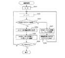
次に、本実施の形態におけるジョブ実行処理について図4〜図6に示したフローチャートを用いて説明する。 Next, job execution processing according to the present embodiment will be described with reference to the flowcharts shown in FIGS.
ジョブ受付部21がn個のジョブをまとめて受け付けると(ステップ101)、ジョブ管理部22は、これらのジョブを受け付けた順にIPSジョブキュー31に登録する(ステップ102)。受け付けたジョブがIPSジョブキュー31に登録されると、予測処理時間算出部23は、制御部28からの指示に従い、各ジョブを画像処理と印刷処理とに分解し、画像処理及び印刷処理それぞれの実行に要する予測処理時間を算出する(ステップ103)。本実施の形態では、画像処理の実行に要する予測画像処理時間と印刷処理の実行に要する予測印刷処理時間とを予測処理時間と総称する。なお、本実施の形態では、処理時間の長短は、処理の実行に要する負荷の大小に依存することを前提にしている。 When the job reception unit 21 receives n jobs at once (step 101), the
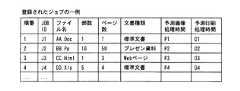
図7には、本実施の形態において受け付けたジョブのリストの一例が示されている。ジョブ受付部21が受け付けたジョブJ1〜J4は、図7に示した順番1〜4でIPSジョブキュー31に登録される。図7には、各ジョブにおいて処理対象となる電子文書のファイル名、当該文書の印刷部数、各文書のページ数、文書の種類が示されている。これらの文書の情報に加えて、図7には、予測処理時間算出部23により算出された各ジョブにおける画像処理に要する予測画像処理時間P1〜P4と印刷処理に要する予測印刷処理時間O1〜O4とが示されている。つまり、ジョブJ1の予測画像処理時間はP1、ジョブJ1の予測印刷処理時間はO1ということになる。なお、各予測処理時間は、図7に示した部数やページ数などの他に、出力用紙サイズ、解像度、原稿サイズ、画像処理種別等のジョブに関する属性値を参照して算出してもよい。 FIG. 7 shows an example of a list of jobs accepted in the present embodiment. The jobs J1 to J4 received by the job receiving unit 21 are registered in the
ところで、本実施の形態においては、IPS15を用いて画像処理を実行するためのジョブキューとしてIPSジョブキュー31と、IOT14を用いて印刷処理を実行するためのジョブキューとしてIOTジョブキュー32と、を別個に設けている。更に、外部のクラウド6を用いて画像処理を実行するためのジョブキューとしてクラウドジョブキュー33を設けている。本実施の形態においては、IPSジョブキュー31のジョブリストをJL_Pと、IOTジョブキュー32のジョブリストをJL_Oと、クラウドジョブキュー33のジョブリストをJL_Cと、それぞれ表すことにする。そして、いずれかのジョブキュー31〜33に登録されるジョブJi(1≦i≦n)の画像処理部分をJPi、印刷処理部分をJOiと表すことにする。但し、説明を簡略するために、Jiの画像処理部分を「ジョブJPi」と、ジョブJiの印刷処理部分を「ジョブJOi」と称する場合もありうる。 By the way, in the present embodiment, an
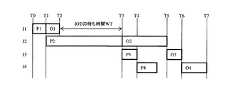
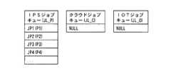
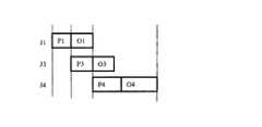
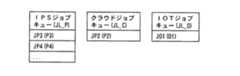
図8Aは、図7に示した各ジョブの予測画像処理時間P1〜P4及び予測印刷処理時間O1〜O4の長さの関係を時系列に並べて示した概念図である。また、図8Bは、図8Aに示した各ジョブの各ジョブキューへの登録状況を示した図である。図8Bを参照すると、IPSジョブキュー31には、ジョブの画像処理JP1〜JP4がこの順番に登録され、この時点では、先頭のジョブJP1に対する処理は終了していないことがわかる。ジョブの印刷処理JOiは、当該ジョブの画像処理JPiの実行結果を印刷する処理であるから、いずれのジョブの画像処理も終了していないこの時点(T0〜T1の間のいずれかの時点)では、IOTジョブキュー32にはジョブが何ら蓄積されていない。また、以降の処理で画像処理の実行先を決定するまでは、ジョブの画像処理JPiはIPSジョブキュー31に蓄積されるので、この時点では、クラウドジョブキュー33にはジョブが何ら蓄積されていない。このジョブが蓄積されていない状態を図8Bでは“NULL”と図示している。以降の図においても同様に図示する。なお、図8Bにおいて、ジョブリストには、ジョブに加えて予測処理時間を括弧内に示すことにする。 FIG. 8A is a conceptual diagram showing the relationship between the lengths of the predicted image processing times P1 to P4 and the predicted print processing times O1 to O4 of each job shown in FIG. 7 in time series. FIG. 8B is a diagram showing the registration status of each job shown in FIG. 8A in each job queue. Referring to FIG. 8B, it can be seen that job image processing JP1 to JP4 are registered in this order in the
図8Aには次のことが示されている。すなわち、画像処理の実行に用いられるIPS15は、IPSジョブキュー31に登録されている1番目のジョブJ1の画像処理JP1(予測画像処理時間P1)の実行後、続けて2番目のジョブJ2の画像処理JP2(予測画像処理時間P2)を実行する。そして、続けて3番目のジョブJ3の画像処理JP3(予測画像処理時間P3)及び4番目のジョブJ4の画像処理JP4(予測画像処理時間P4)を実行する。この画像処理の実行の際、IPS15の待ち時間はない。 The following is shown in FIG. 8A. In other words, the
一方、処理の実行に用いられるIOT14も同様に、1番目のジョブJ1の印刷処理JO1(予測印刷処理時間O1)から4番目のジョブJ4の印刷処理JO4(予測印刷処理時間O4)まで順番にジョブを実行する。しかしながら、この例の印刷処理の場合、2番目のジョブJO2の予測印刷処理時間O2が直前の1番目のジョブの予測画像処理時間O1より長いため、1番目のジョブの印刷処理JO1を実行してから2番目のジョブの印刷処理JO2を実行するまでの間にIOT14に待ち時間WT(=T3−T1+O1)が発生してしまう。すなわち、ジョブの受付順にジョブを処理していくと、各ジョブの画像処理及び印刷処理の各時間長によってIOT14に待ち時間が発生してしまい、IOT14の稼働率の低下につながりかねない。特に、IOT14の稼働率は、i(1≦i<n)番目のジョブの印刷処理の予測印刷処理時間と、直後のi+1番目のジョブの画像処理の予測画像処理時間との長さの関係に影響を受けやすい。そこで、本実施の形態においては、ステップ103において算出した予測処理時間を参照して、IOT14における待ち時間の発生の有無を事前に検証し、その検証結果に基づいてIPSジョブキュー31にいったん登録されたジョブについて画像処理の実行先を改めて決定するようにした(ステップ104)。この処理について、更に詳述する。 On the other hand, the
すなわち、制御部28は、IPSジョブキュー31の先頭に登録されているi(1≦i<n)番目のジョブの予測画像処理時間と、i+1番目のジョブの画像処理の予測画像処理時間とを比較する。なお、IPSジョブキュー31の先頭に登録されているジョブJiは、現時点において画像処理の実行がすでに開始されているとも言える。図8に示した例だと、ジョブJ1の予測印刷処理時間O1と、ジョブJ2の予測画像処理時間P2とを比較する。その比較の結果、O1≧P2であれば、IOT14の待ち時間は発生しないので、ジョブJP2をIPSジョブキュー31に登録したままとし、IPS15に実行させる。すなわち、画像処理の実行先をIPS15と決定する。 That is, the
一方、予測処理時間の比較の結果、O1<P2であれば、IOT14の待ち時間は、図8Aに例示したように発生することになる。つまり、ジョブJP2をIPS15に実行させると、IOT14の待ち時間が発生するので、この場合、ジョブJP2をクラウド6に実行させる。すなわち、画像処理の実行先をクラウド6と決定する。この場合、ジョブJP2は、後述するようにIPSジョブキュー31からクラウドジョブキュー33へ移動される。より詳細には、IPSジョブキュー31から削除され、クラウドジョブキュー33に登録されることになる。なお、このジョブの移動は、制御部28からの指示に従いジョブ管理部22により行われる。 On the other hand, as a result of the comparison of the predicted processing times, if O1 <P2, the waiting time of the
本実施の形態では、以上のようにi番目の印刷処理の予測印刷処理時間と、i+1番目のジョブの画像処理の予測画像処理時間との比較結果に応じて画像処理の実行先を決定する。この決定内容は、追って説明する画像処理の実行時に使用するので、RAM17等に一時保存しておく。なお、以降の説明では、受け付けたジョブJ1〜J4のうちジョブJ2の画像処理JP2のみが直前のジョブJ1の印刷処理JO1の処理時間より長いために画像処理の実行先がクラウド6と決定されたものとして説明する。IPSジョブキュー31の登録内容は、ジョブJP2が削除されたことで変更され、画像処理実行部35は、IPSジョブキュー31において変更された並び順でジョブJPiを実行することになる。このときの状態を図9Aに示す。 In the present embodiment, as described above, the execution destination of the image processing is determined according to the comparison result between the predicted print processing time of the i-th print processing and the predicted image processing time of the image processing of the i + 1th job. Since this determination content is used when image processing to be described later is executed, it is temporarily stored in the
以上のようにして、受け付けたジョブJ1〜J4に対し、画像処理の実行先が決定されると、ジョブ実行部24は、制御部28からの指示に従い、画像処理及び印刷処理の実行を開始する(ステップ105,106)。ただ、画像処理の実行結果を印刷する印刷処理は、実行が開始されても、IOTジョブキュー32にジョブが登録されるまでは待機状態である。なお、各処理の実行開始は、どちらが先でもよい。 As described above, when the execution destination of the image processing is determined for the received jobs J1 to J4, the
次に、本実施の形態における画像処理について図5に示したフローチャートを用いて説明する。 Next, image processing in the present embodiment will be described with reference to the flowchart shown in FIG.
まず、制御部28は、ジョブを識別するための変数iを0に初期化する(ステップ201)。続いて、変数iに1を加算して、処理対象とするジョブを特定する(ステップ202)。次に、前述したステップ104において決定した画像処理の実行先を参照し、当該ジョブJPiの実行先がIPS15の場合(ステップ203でN)、画像処理実行部35は、IPSジョブキュー31のジョブリストの先頭に登録されているジョブJiの画像処理JPiを実行する(ステップ204)。そして、画像処理JPiが終了すると、ジョブ管理部22は、ジョブJiの画像処理JPiをIPSジョブキュー31のジョブリストから削除すると共に、ジョブJiの印刷処理JOiをIOTジョブキュー32のリストに登録する(ステップ205)。図9Aの設定例に従うと、ジョブJP1は、IPS15を用いて実行される。 First, the
続いて、IPSジョブキュー31は空“NULL”ではないので(ステップ206でN)、ステップ202に戻り、変数iに1を加算して、処理対象とするジョブJ2を特定する(ステップ202)。次に、前述したステップ104において決定した画像処理の実行先を参照する。本実施の形態の設定例では、ジョブJP2の実行先はクラウド6と決定されている。よって、ジョブJP2の実行先がクラウド6の場合(ステップ203でY)、制御部28は、画像処理JP2の実行をクラウド6に指示することになるが、そのために、ジョブ管理部22は、制御部28からの指示に従い、ジョブJP2をIPSジョブキュー31のジョブリストから削除し、クラウドジョブキュー33のジョブリストに登録する(ステップ207)。続いて、ジョブ実行要求送信部25は、制御部28からの指示に従い、ジョブ実行要求をクラウド6へ向けて送信することでジョブJP2の実行を指示する(ステップ208)。ジョブ実行要求には、ジョブJP2の実行内容を特定する情報、画像形成装置10のIPアドレスやメールアドレスなどジョブ実行の依頼元を特定する情報、ジョブの実行結果の返信方法等、ジョブJP2の実行及び実行結果の返信に必要な情報が含まれている。 Subsequently, since the
クラウド6において、要求受付部61が画像形成装置10からのジョブ実行要求を受信すると、ジョブ実行部62がその要求に応じてジョブJP2を実行する。そして、終了通知送信部63は、ジョブJP2の実行の終了をジョブ実行依頼元の画像形成装置10へ通知する。この通知に関しては、ジョブの実行結果を返すことで、これを終了通知としてもよい。あるいは、終了通知のみを返し、実行結果は、画像形成装置10からの送信要求に応じて別途返すようにしてもよい。この終了通知と実行結果とのやり取りは、画像形成装置10とクラウド6との間で予め決めておいてもよいし、画像形成装置10がクラウド6にジョブ実行要求時に指定してもよい。 In the
続いて、IPSジョブキュー31は空“NULL”ではないので(ステップ206でN)、ステップ202に戻り、変数iに1を加算して、処理対象とするジョブJ3を特定する(ステップ202)。本実施の形態では、ジョブJP3、更にはジョブJP4もIPS15を用いて実行されるものとしている。つまり、ジョブJP3,ジョブJP4に関しては、ジョブJP1と同じ処理内容となるので、説明を省略する。 Subsequently, since the
このようにして、IPSジョブキュー31が空“NULL”になると(ステップ206でY)、画像処理は終了する。 In this way, when the
図9Aは、図8Aに対し、ジョブJP2がクラウド6を利用して実行することが決定された場合について各ジョブを時系列に並べて示した概念図である。図8Aと比較すると理解できるように、ジョブJP2の実行にクラウド6を利用するようにしたためIOT待ち時間WTが消失する。図9Bは、ジョブJP2の実行にクラウド6を利用する場合のIPSジョブキュー31とクラウドジョブキュー33の各ジョブリストを示した。図9Bに示したように、ジョブJP2は、IPSジョブキュー31からクラウドジョブキュー33に移されたようになる。 FIG. 9A is a conceptual diagram in which each job is arranged in chronological order when it is determined that the job JP2 is executed using the
図10Aは、図9Aにおいて、ジョブJ1の画像処理JP1の実行が終了したときの各ジョブを時系列に並べて示した概念図である。図10Aにおいては、ジョブJP1(予測画像処理時間P1)が終了したことを示すために破線で図示している。そして、図10Bは、ジョブJ1の画像処理JP1がIPSジョブキュー31から削除され、当該ジョブJ1の印刷処理JO1がIOTジョブキュー32のジョブリストに登録された状態を示した図である。これは、i=1のときのステップ205が終了し、更にi=2のときのステップ207が終了した時点の各ジョブキュー31〜33の登録状態を示している。 FIG. 10A is a conceptual diagram in which the jobs when the execution of the image processing JP1 of the job J1 is finished in FIG. 9A are arranged in time series. In FIG. 10A, a broken line is shown to indicate that the job JP1 (predicted image processing time P1) has ended. FIG. 10B is a diagram illustrating a state in which the image processing JP1 of the job J1 is deleted from the
次に、本実施の形態における印刷処理について図6に示したフローチャートを用いて説明する。 Next, the printing process in this embodiment will be described with reference to the flowchart shown in FIG.
まず、制御部28は、ジョブを識別するための変数iを0に初期化する(ステップ301)。続いて、変数iに1を加算して、処理対象とするジョブを特定する(ステップ302)。次に、印刷処理JOiがIOTジョブキュー32に存在しているかを確認し、存在していれば(ステップ303でY)、印刷処理実行部36は、IOTジョブキュー32のジョブリストの先頭に登録されているジョブJiの印刷処理JOiを実行する(ステップ304)。そして、印刷処理JOiが終了すると、ジョブ管理部22は、ジョブJiの印刷処理JOiをIOTジョブキュー32のジョブリストから削除する(ステップ305)。i=1の場合、すなわちジョブJO1は、以上のようにして印刷処理が実行される。 First, the
ステップ302に戻り、変数iに1を加算して、処理対象とするジョブを特定する(ステップ302)。i=2の場合、JO2がIOTジョブキュー32に存在されているかを確認する。なお、この時点では、まだジョブJP2の終了通知を確認できていないためにジョブJO2がIOTジョブキュー32に登録されていないことにする(ステップ303でN)。続いて、ジョブJP2がクラウドジョブキュー33に存在しているかを確認する。これは、前述したように、印刷処理JP2の実行をクラウド6に依頼し、また前述したジョブJP2が終了していないという条件のもとでは、ジョブJP2はクラウドジョブキュー33に存在しているはずである。この場合(ステップ306でY)、制御部28は、続いてジョブJP2の実行が終了しているのか確認する。これは、終了通知受信部26が終了通知送信部63から送信された終了通知をすでに受信していれば、終了していたことになる。なお、終了通知受信部26がこの時点で、ジョブJP2の実行が終了しているのかをクラウド6に問い合わせるようにしてもよい。 Returning to Step 302, 1 is added to the variable i to specify the job to be processed (Step 302). When i = 2, it is confirmed whether JO2 exists in the
終了通知受信部26からの終了通知を受けていないことで、ジョブJP2の実行が終了していない場合(ステップ307でN)、ステップ302に戻る。 If the execution of the job JP2 has not ended due to not receiving the end notification from the end notification receiving unit 26 (N in Step 307), the process returns to Step 302.
一方、終了通知受信部26からの終了通知を受けたことで、ジョブJP2の実行が終了していたことを確認した場合(ステップ307でY)、ジョブ管理部22は、ジョブJ2の画像処理JP2をクラウドジョブキュー33から削除すると共に、ジョブJ2の印刷処理JO2をIOTジョブキュー32に登録する(ステップ308)。その後は、JO1の場合と同様に、印刷処理実行部36は、IOTジョブキュー32のジョブリストの先頭に登録されているジョブJ2の印刷処理JO2を実行し(ステップ304)、その印刷処理JO2が終了すると、ジョブ管理部22は、ジョブJ2の印刷処理JO2をIOTジョブキュー32のジョブリストから削除する(ステップ305)。 On the other hand, when it is confirmed that the execution of the job JP2 has ended by receiving the end notification from the end notification receiving unit 26 (Y in step 307), the
ステップ302に戻り、変数iに1を加算して、処理対象とするジョブを特定する(ステップ302)。i=3の場合、ジョブJ3の画像処理JP3が終了し、ジョブJ3の印刷処理JO3がIOTジョブキュー32の先頭に登録されていれば、前述したジョブJO1と同様に処理される(ステップ303でY,304,305)。あるいは、ジョブJ3の画像処理JP3がまだ終了していなければ、ジョブJ3の印刷処理JO3は、IOTジョブキュー32に登録されていないし(ステップ303でN)、クラウドジョブキュー33にも登録されていない(ステップ306でN)。更に、受け付けたジョブの数(n=4)にも達していないので(ステップ309でN)、ジョブJ3に関しては、IOT14による印刷処理はまだ実行できる状態にない。よって、処理はステップ302に戻る。 Returning to Step 302, 1 is added to the variable i to specify the job to be processed (Step 302). When i = 3, if the image processing JP3 of the job J3 is completed and the print processing JO3 of the job J3 is registered at the head of the
続いて、変数iに1を加算して、処理対象とするジョブを特定する(ステップ302)。i=4の場合、ジョブJP3が終了していないので、ジョブJP4も終了しておらず、よって印刷処理はまだ実行できる状態にない。ここで、iとNは、共に4で等しい値である(ステップ309でY)。JL_Oが空“NULL”でない場合には(ステップ310でN)、ステップ301に戻り、前述した処理を繰り返し実行する。 Subsequently, 1 is added to the variable i to specify a job to be processed (step 302). If i = 4, the job JP3 has not ended, so the job JP4 has not ended, and the printing process is not yet ready for execution. Here, i and N are both equal to 4 (Y in step 309). If JL_O is not empty “NULL” (N in step 310), the process returns to step 301 to repeat the above-described processing.
図11Aは、図10Aにおいて、ジョブJ1の画像処理JP1及び印刷処理JO1、ジョブJ3の画像処理JP3が終了したときの各ジョブを時系列に並べて示した概念図である。なお、図11Aにおいても、図10Aと同様、終了した画像処理又は印刷処理は破線で図示している。まず、図11Aによると、画像処理JP1,JP3が終了しているので、図11Bに示したように、IPSジョブキュー31には、ジョブJP4だけが存在している。そして、印刷処理JO1が終了しているので、図11Bに示したように、IOTジョブキュー32にはJO1が登録されていない。一方、ジョブJO3は終了していないので、IOTジョブキュー32にはジョブJO3が存在する。なお、図11Bには、ジョブJP3の後にジョブJP2が終了したので、IOTジョブキュー32には、ジョブJO3がジョブJO2より前に登録されているが、本来の並び順になるように、ジョブJP3の後にジョブJP2が終了した場合でも、ジョブJO2をジョブJO3の前に登録するようにしてもよい。 FIG. 11A is a conceptual diagram in which the jobs when the image processing JP1 and the printing processing JO1 of the job J1 and the image processing JP3 of the job J3 are completed in FIG. 10A are arranged in time series. Also in FIG. 11A, similar to FIG. 10A, the completed image processing or printing processing is indicated by a broken line. First, according to FIG. 11A, since the image processing JP1 and JP3 have been completed, only the job JP4 exists in the
更に、図11Aでは、図10Aと異なり、まだ処理が終了していないジョブJO2(予測印刷処理時間O2)が示されていることから、現時点では、クラウド6によるジョブJP2の実行が終了していることも把握できる。また、ジョブJO2はまだ終了していないので、ジョブJO3と同様、IOTジョブキュー32に存在している。なお、図11A,図11Bに示されているように、クラウド6によるジョブJP2は、IPS15によるジョブJP3の実行終了後に終了したことが把握できる。 Further, in FIG. 11A, unlike FIG. 10A, job JO2 (predicted print processing time O2) that has not yet been processed is shown. Therefore, execution of job JP2 by
実施の形態2.
上記実施の形態1においては、ジョブがIPSジョブキュー31に登録された順番に実行されることを前提としつつ、ジョブJi(iは自然数)の印刷処理JOiよりジョブJk(k=i+1)の画像処理JPkの方が直前の予測処理時間が長い場合には、ジョブJkの画像処理JPkの実行をクラウド6に依頼するようにした。
In the first embodiment, the image of the job Jk (k = i + 1) from the print processing JOi of the job Ji (i is a natural number), assuming that the jobs are executed in the order registered in the
本実施の形態では、上記前提を前提とはせずに、受け付けたジョブを画像処理の実行先を決定する前に並び替えるようにしたことを特徴としている。具体的には、図4におけるステップ103とステップ104の間に次の処理を行う。 The present embodiment is characterized in that the received job is rearranged before determining the execution destination of the image processing without assuming the above premise. Specifically, the following processing is performed between step 103 and step 104 in FIG.
まず、受け付けたジョブJ1〜J4のうち先頭のジョブJ1の画像処理JP1に関しては、実行が開始されているなどによって最初にIPS15において実行されることにすると、制御部28は、このJ1の印刷処理JO1と、まだ実行されていない残りのジョブ2,3,4の画像処理JP2,JP3,JP4との差分を求め、更に各差分の絶対値を求める。そして、絶対値が最小値となるジョブを、ジョブJ1に続いて実行するジョブとして決定する。つまり、印刷処理JO1の予測印刷処理時間と最も近い予測画像処理時間となるジョブが次に実行するジョブとして選択される。なお、この選択されたジョブを例えばJ3とする。 First, regarding the image processing JP1 of the first job J1 among the received jobs J1 to J4, if the execution is started first in the
次に、制御部28は、上記と同様に、このJ3の印刷処理JO3と、ジョブJ1とJ3を除くまだ実行されていない残りのジョブJ2,J4の各画像処理との差分を求め、更に各差分の絶対値を求める。そして、絶対値が最小値となるジョブを、J3に続いて実行するジョブとして決定する。つまり、印刷処理JO3の予測印刷処理時間と最も近い予測画像処理時間となるジョブが選択される。 Next, similarly to the above, the
以上の処理を残りが1つになるまで繰り返し行う。そして、残った1つのジョブは最後に実行されるジョブとして決定される。 The above processing is repeated until there is only one remaining. The remaining job is determined as the job to be executed last.
以上のようにして、実行されるジョブの順番が決定されると、続いて、画像処理の実行先を決定する。本実施の形態では、実施の形態1と異なり、上記処理にて算出した絶対値が予め決められた閾値より大きい値となったときには後段のジョブの画像処理の実行先をクラウド6と決定する。つまり、|JOj−JPk|>thとなる場合に、Jkの画像処理JPkの実行先をクラウド6とする。但し、jとkは自然数であり、thは閾値である。画像処理及び印刷処理に関しては、実施の形態1と同じなので説明を省略する。 When the order of jobs to be executed is determined as described above, the execution destination of image processing is subsequently determined. In the present embodiment, unlike the first embodiment, when the absolute value calculated in the above processing is larger than a predetermined threshold, the execution destination of the image processing of the subsequent job is determined as the
前述したように、本実施の形態において、画像処理の結果を印刷する印刷処理は、ジョブを受け付けた画像形成装置10のIOT14を用いて実行することを前提としている。従って、画像処理をクラウド6に依頼したジョブJ2の印刷処理JO2を含めて全ての印刷処理JO1〜JO4は、IOTジョブキュー32に登録され、IOT14によって処理される。ただ、本実施の形態は、ジョブの印刷処理(後処理)を実行する出力手段としてのIOT14の稼働率の向上を図るためのものである。本実施の形態では、出力手段を複数設けることは前提としていないが、出力手段が画像形成装置10に内蔵されていることは必須ではない。 As described above, in the present embodiment, it is assumed that the print processing for printing the image processing result is executed using the
また、本実施の形態では、ジョブ実行装置として画像形成装置10を例にして説明した。従って、ジョブに含まれる処理は、画像データの生成、加工、変換等画像データを取り扱う画像処理と、生成した画像データを印刷する印刷処理とが基本的には含まれている。従って、本実施の形態においては、画像形成装置10において取り扱うジョブに含まれる処理を、画像処理と印刷処理に大別し、画像処理を前処理として、印刷処理を後処理として取り扱うようにした。但し、本実施の形態においては、後処理において用いる出力手段の稼働率の向上を図るものなので、出力手段を用いない前処理は、更に複数に分解されていてもよい。 In this embodiment, the
また、前処理及び後処理それぞれの実行に要する負荷を表す指標値として時間という指標を用いたが、これに限定するものではなく負荷の度合いを表現しうる指標であれば、他のデータを用いてもよい。 In addition, although the index of time is used as an index value representing the load required to execute each of the pre-processing and post-processing, the present invention is not limited to this, and other data can be used as long as the index can express the degree of load. May be.
また、本実施の形態では、実行中の処理はそのまま継続して実行されることにしたが、予測処理時間を比較した結果、画像処理の実行途中でも、中断してでもクラウド6に当該画像処理の実行を依頼した方がよいと判断したときには、クラウド6に当該画像処理の実行を指示する。この際、処理効率を判断材料として、途中まで行った画像処理の途中結果をクラウド6に送ってもよいし、クラウド6側において最初からやり直してもよい。 Further, in the present embodiment, the process being executed is continuously executed as it is. However, as a result of comparing the prediction processing times, the image processing is performed in the
また、上記説明では、ジョブ受付部21がまとめて受け付けたジョブを対象に説明をしたが、ジョブの実行中に他のジョブを追加して受け付けた場合には、それらのジョブも前述しジョブ実行処理の対象に付け加えてもよい。 In the above description, the jobs received by the job receiving unit 21 are described as targets. However, when other jobs are additionally received during job execution, these jobs are also described above. You may add to the object of processing.
また、出力手段の出力形態としては、印刷部27による印刷物を例にしたが、例えば電子ファイルなどの電子データを後処理の結果得られるものとしてもよい。 Further, as an output form of the output means, a printed matter by the
2 PC(パーソナルコンピュータ)、4 ネットワーク、6 クラウド、10 画像形成装置、11 CPU、12 操作パネル、13 IIT、14 IOT、15 IPS、16 ROM、17 RAM、18 HDD、19 ネットワークインタフェース(I/F)、20 アドレスデータバス、21 ジョブ受付部、22 ジョブ管理部、23 予測処理時間算出部、24 ジョブ実行部、25 ジョブ実行要求送信部、26 終了通知受信部、27 印刷部、28 制御部、31 IPSジョブキュー、32 IOTジョブキュー、33 クラウドジョブキュー、35 画像処理実行部、36 印刷処理実行部、61 要求受付部、62 ジョブ実行部、63 終了通知送信部。 2 PC (personal computer), 4 network, 6 cloud, 10 image forming apparatus, 11 CPU, 12 operation panel, 13 IIT, 14 IOT, 15 IPS, 16 ROM, 17 RAM, 18 HDD, 19 network interface (I / F) ), 20 address data bus, 21 job reception unit, 22 job management unit, 23 predicted processing time calculation unit, 24 job execution unit, 25 job execution request transmission unit, 26 end notification reception unit, 27 printing unit, 28 control unit, 31 IPS job queue, 32 IOT job queue, 33 cloud job queue, 35 image processing execution unit, 36 print processing execution unit, 61 request reception unit, 62 job execution unit, 63 end notification transmission unit.
Claims (3)
Translated fromJapanese受け付けたn(nは2以上の自然数)個のジョブのそれぞれについて、前記ジョブのうち情報を生成する前処理の実行に要する時間である前処理時間と、前記前処理により生成された情報を出力手段に出力させる後処理の実行に要する時間である後処理時間と、を算出する算出手段と、
前記受付手段により受け付けられたジョブであって、前処理用ジョブキューに登録されたジョブの前記前処理を順番に実行する前処理実行手段と、
前記前処理の実行終了後に後処理用ジョブキューに登録されたジョブの前記後処理を順番に実行する後処理実行手段と、
前記算出手段により算出されたi(1≦i<n)番目のジョブの前記後処理時間と、i+1番目以降の各ジョブの前記前処理時間との差の絶対値を求め、前記絶対値の小さい順に、前記前処理用ジョブキューに登録されているi+1番目以降のジョブを並び替える並替手段と、
を有するジョブ実行装置。A reception means for receiving a job;
For each of the received n (n is a natural number of 2 or more) jobs, the preprocessing time that is the time required to execute the preprocessing for generating information among the jobs and the information generated by the preprocessing are output. A calculation means for calculating a post-processing time which is a time required for execution of the post-processing to be output to the means;
Preprocessing execution means for sequentially executing the preprocessing of the jobs received by the receiving means and registered in the preprocessing job queue;
Post-processing execution means for sequentially executing the post-processing of jobs registered in a post-processing job queue after completion of execution of the pre-processing;
An absolute value of a difference between the post-processing time of the i (1 ≦ i <n) -th job calculated by the calculation means and the pre-processing time of each of the i + 1th and subsequent jobs is obtained, and the absolute value is small. Reordering means for reordering the i + 1th and subsequent jobs registered in the preprocessing job queue in order;
A job execution apparatus.
その閾値を超えたジョブの実行終了通知を前記外部のジョブ実行装置から受信すると、その閾値を超えたジョブの後処理を前記後処理用ジョブキューに登録する、
ことを特徴とする請求項1に記載のジョブ実行装置。When the absolute value exceeds a predetermined threshold, the control means deletes a job exceeding the threshold from the preprocessing job queue and executes preprocessing of the job exceeding the threshold. Instruct the external job execution device,
When an execution end notification of a job exceeding the threshold is received from the external job execution device, post-processing of the job exceeding the threshold is registered in the post-processing job queue.
The job execution apparatus according to claim1 , wherein:
前記出力手段は、搭載された画像出力装置であり、
前記前処理は、搭載された画像処理装置又は外部の画像処理装置の少なくとも一方を用いて実行される画像処理であり、
前記後処理は、前記画像出力装置を用いて実行される印刷処理である、
ことを特徴とする画像形成装置。The job execution device according to claim 1or 2 is installed,
The output means is a mounted image output device;
The preprocessing is image processing executed using at least one of an installed image processing apparatus or an external image processing apparatus,
The post-processing is printing processing executed using the image output device.
An image forming apparatus.
Priority Applications (3)
| Application Number | Priority Date | Filing Date | Title |
|---|---|---|---|
| JP2010180081AJP5716316B2 (en) | 2010-08-11 | 2010-08-11 | Job execution apparatus and image forming apparatus |
| US13/041,515US8726291B2 (en) | 2010-08-11 | 2011-03-07 | Job execution apparatus, image forming apparatus, computer readable medium and job execution system |
| US14/220,870US9298403B2 (en) | 2010-08-11 | 2014-03-20 | Job execution apparatus, image forming apparatus, computer readable medium and job execution system |
Applications Claiming Priority (1)
| Application Number | Priority Date | Filing Date | Title |
|---|---|---|---|
| JP2010180081AJP5716316B2 (en) | 2010-08-11 | 2010-08-11 | Job execution apparatus and image forming apparatus |
Publications (2)
| Publication Number | Publication Date |
|---|---|
| JP2012035587A JP2012035587A (en) | 2012-02-23 |
| JP5716316B2true JP5716316B2 (en) | 2015-05-13 |
Family
ID=45565730
Family Applications (1)
| Application Number | Title | Priority Date | Filing Date |
|---|---|---|---|
| JP2010180081AExpired - Fee RelatedJP5716316B2 (en) | 2010-08-11 | 2010-08-11 | Job execution apparatus and image forming apparatus |
Country Status (2)
| Country | Link |
|---|---|
| US (2) | US8726291B2 (en) |
| JP (1) | JP5716316B2 (en) |
Families Citing this family (12)
| Publication number | Priority date | Publication date | Assignee | Title |
|---|---|---|---|---|
| JP2011218793A (en)* | 2010-03-25 | 2011-11-04 | Fuji Xerox Co Ltd | Image processing apparatus and image processing program |
| US20120297066A1 (en)* | 2011-05-19 | 2012-11-22 | Siemens Aktiengesellschaft | Method and system for apparatus means for providing a service requested by a client in a public cloud infrastructure |
| CN103945269A (en)* | 2013-01-21 | 2014-07-23 | 珠海扬智电子科技有限公司 | Retrieval method and digital stream system |
| JP6299101B2 (en)* | 2013-07-26 | 2018-03-28 | 株式会社リコー | Service providing system, service providing method and program |
| JP6303312B2 (en)* | 2013-07-26 | 2018-04-04 | 株式会社リコー | Service providing system and image providing method |
| JP2015028740A (en)* | 2013-07-31 | 2015-02-12 | 株式会社リコー | Service provision system, service provision method, and program |
| CN104545849B (en)* | 2015-02-04 | 2017-02-22 | 成都信息工程大学 | Special Internet of Things information control terminal for hospital sickroom |
| US9465994B1 (en)* | 2015-02-23 | 2016-10-11 | Amazon Technologies, Inc. | Predicting performance and success of large-scale vision algorithms |
| US9507546B2 (en)* | 2015-02-26 | 2016-11-29 | Konica Minolta Laboratory U.S.A., Inc. | Method for producing packages of printed materials by generating and executing a job set containing multiple linked sub-jobs |
| JP2018124605A (en)* | 2017-01-30 | 2018-08-09 | オムロン株式会社 | Image processing system, information processing apparatus, information processing method, and information processing program |
| CN112256214A (en)* | 2020-11-02 | 2021-01-22 | 珠海奔图电子有限公司 | Job cancel printing method, image forming apparatus, image forming system, and computer storage medium |
| US11914906B2 (en) | 2022-05-17 | 2024-02-27 | Kyocera Document Solutions Inc. | Pre-processing print jobs |
Family Cites Families (12)
| Publication number | Priority date | Publication date | Assignee | Title |
|---|---|---|---|---|
| JPH02200126A (en) | 1989-01-26 | 1990-08-08 | Chuzo Tsuruta | Fruit body retaining tool |
| JPH02220126A (en)* | 1989-02-22 | 1990-09-03 | Toshiba Corp | Printer controller |
| JP3175620B2 (en) | 1996-06-21 | 2001-06-11 | セイコーエプソン株式会社 | Printing equipment |
| JPH10240467A (en) | 1997-02-27 | 1998-09-11 | Canon Inc | Image processing apparatus and control method thereof |
| US6762857B1 (en)* | 1999-11-29 | 2004-07-13 | Xerox Corporation | Method and apparatus to enable processing multiple capabilities for a sub-job when using a set of commonly shared resources |
| JP2002182875A (en)* | 2000-12-19 | 2002-06-28 | Dainippon Screen Mfg Co Ltd | Printing controller, printing control method and recording medium |
| JP2003167703A (en)* | 2001-11-30 | 2003-06-13 | Fujitsu Ltd | Printer, printer system, printer job processing method, and program therefor |
| JP2003241913A (en)* | 2002-02-15 | 2003-08-29 | Canon Inc | Output device, information processing device, information processing system, information processing method, recording medium, and program |
| US7495791B2 (en)* | 2004-10-06 | 2009-02-24 | Xerox Corporation | Load sharing among networked image processing devices |
| JP2007237554A (en)* | 2006-03-08 | 2007-09-20 | Sharp Corp | Image forming apparatus, job scheduling method, program, and recording medium |
| JP4771074B2 (en)* | 2006-04-03 | 2011-09-14 | 富士ゼロックス株式会社 | Print control apparatus, print control method, and program |
| JP2008044122A (en)* | 2006-08-11 | 2008-02-28 | Fuji Xerox Co Ltd | Printer |
- 2010
- 2010-08-11JPJP2010180081Apatent/JP5716316B2/ennot_activeExpired - Fee Related
- 2011
- 2011-03-07USUS13/041,515patent/US8726291B2/ennot_activeExpired - Fee Related
- 2014
- 2014-03-20USUS14/220,870patent/US9298403B2/ennot_activeExpired - Fee Related
Also Published As
| Publication number | Publication date |
|---|---|
| US20120042323A1 (en) | 2012-02-16 |
| US20140204420A1 (en) | 2014-07-24 |
| US8726291B2 (en) | 2014-05-13 |
| US9298403B2 (en) | 2016-03-29 |
| JP2012035587A (en) | 2012-02-23 |
Similar Documents
| Publication | Publication Date | Title |
|---|---|---|
| JP5716316B2 (en) | Job execution apparatus and image forming apparatus | |
| US8505011B2 (en) | Method of optimizing job distribution process by analysis of transmission time and processing time | |
| JP5605746B2 (en) | Print control apparatus, image forming system, and program | |
| US8863142B2 (en) | Image forming apparatus | |
| JP6555892B2 (en) | Image forming apparatus and printing control method using image forming apparatus | |
| US9928013B2 (en) | Print control system, method of controlling printing, and recording medium | |
| WO2008063622A1 (en) | Methods and systems rendering a print job | |
| JP2012059093A (en) | Printer controller, printing system and program | |
| CN111610939A (en) | Image forming apparatus, control method thereof, and computer-readable storage medium | |
| US20120243022A1 (en) | Image processing system and image processing control apparatus | |
| US8730498B2 (en) | Information processing apparatus, control method, and computer-readable storage medium | |
| US9785871B2 (en) | Print control device and non-transitory computer readable medium | |
| US20120250053A1 (en) | Method and system for handling sub-jobs | |
| JP6127716B2 (en) | Printing device | |
| US8665460B2 (en) | Print system, printing apparatus, printing method and printing program | |
| JP6067039B2 (en) | Image processing apparatus, image processing method and program for obtaining predicted value of time required for printing | |
| JP6996189B2 (en) | Print controller, image forming system and image forming device | |
| JP2021056756A (en) | Support program, information processor and printing method | |
| JP5441009B2 (en) | Print control apparatus, image forming system, and program | |
| JP6185745B2 (en) | Print control apparatus, print control method, and program | |
| JP5672721B2 (en) | Image forming apparatus, image forming program, and image forming method | |
| US8914591B2 (en) | Information processing apparatus, method for controlling same | |
| JP3897083B2 (en) | Print processing apparatus and print processing method | |
| JP6044394B2 (en) | Job processing apparatus, job control method, and computer program | |
| JP2009020752A (en) | Print job generation device and program |
Legal Events
| Date | Code | Title | Description |
|---|---|---|---|
| A621 | Written request for application examination | Free format text:JAPANESE INTERMEDIATE CODE: A621 Effective date:20130724 | |
| A131 | Notification of reasons for refusal | Free format text:JAPANESE INTERMEDIATE CODE: A131 Effective date:20140624 | |
| A521 | Request for written amendment filed | Free format text:JAPANESE INTERMEDIATE CODE: A523 Effective date:20140820 | |
| A131 | Notification of reasons for refusal | Free format text:JAPANESE INTERMEDIATE CODE: A131 Effective date:20140930 | |
| A521 | Request for written amendment filed | Free format text:JAPANESE INTERMEDIATE CODE: A523 Effective date:20141126 | |
| TRDD | Decision of grant or rejection written | ||
| A01 | Written decision to grant a patent or to grant a registration (utility model) | Free format text:JAPANESE INTERMEDIATE CODE: A01 Effective date:20150217 | |
| A61 | First payment of annual fees (during grant procedure) | Free format text:JAPANESE INTERMEDIATE CODE: A61 Effective date:20150302 | |
| R150 | Certificate of patent or registration of utility model | Ref document number:5716316 Country of ref document:JP Free format text:JAPANESE INTERMEDIATE CODE: R150 | |
| S533 | Written request for registration of change of name | Free format text:JAPANESE INTERMEDIATE CODE: R313533 | |
| R350 | Written notification of registration of transfer | Free format text:JAPANESE INTERMEDIATE CODE: R350 | |
| LAPS | Cancellation because of no payment of annual fees |