JP5714794B2 - Spray gun having display and control member - Google Patents
Spray gun having display and control memberDownload PDFInfo
- Publication number
- JP5714794B2 JP5714794B2JP2008280652AJP2008280652AJP5714794B2JP 5714794 B2JP5714794 B2JP 5714794B2JP 2008280652 AJP2008280652 AJP 2008280652AJP 2008280652 AJP2008280652 AJP 2008280652AJP 5714794 B2JP5714794 B2JP 5714794B2
- Authority
- JP
- Japan
- Prior art keywords
- display
- coating material
- displayed
- manual
- coating
- Prior art date
- Legal status (The legal status is an assumption and is not a legal conclusion. Google has not performed a legal analysis and makes no representation as to the accuracy of the status listed.)
- Active
Links
Images


Classifications
- B—PERFORMING OPERATIONS; TRANSPORTING
- B05—SPRAYING OR ATOMISING IN GENERAL; APPLYING FLUENT MATERIALS TO SURFACES, IN GENERAL
- B05B—SPRAYING APPARATUS; ATOMISING APPARATUS; NOZZLES
- B05B12/00—Arrangements for controlling delivery; Arrangements for controlling the spray area
- B05B12/004—Arrangements for controlling delivery; Arrangements for controlling the spray area comprising sensors for monitoring the delivery, e.g. by displaying the sensed value or generating an alarm
- B05B12/006—Pressure or flow rate sensors
- B05B12/008—Pressure or flow rate sensors integrated in or attached to a discharge apparatus, e.g. a spray gun
- B—PERFORMING OPERATIONS; TRANSPORTING
- B05—SPRAYING OR ATOMISING IN GENERAL; APPLYING FLUENT MATERIALS TO SURFACES, IN GENERAL
- B05B—SPRAYING APPARATUS; ATOMISING APPARATUS; NOZZLES
- B05B12/00—Arrangements for controlling delivery; Arrangements for controlling the spray area
- B05B12/002—Manually-actuated controlling means, e.g. push buttons, levers or triggers
- B—PERFORMING OPERATIONS; TRANSPORTING
- B05—SPRAYING OR ATOMISING IN GENERAL; APPLYING FLUENT MATERIALS TO SURFACES, IN GENERAL
- B05B—SPRAYING APPARATUS; ATOMISING APPARATUS; NOZZLES
- B05B15/00—Details of spraying plant or spraying apparatus not otherwise provided for; Accessories
- B05B15/50—Arrangements for cleaning; Arrangements for preventing deposits, drying-out or blockage; Arrangements for detecting improper discharge caused by the presence of foreign matter
- B05B15/55—Arrangements for cleaning; Arrangements for preventing deposits, drying-out or blockage; Arrangements for detecting improper discharge caused by the presence of foreign matter using cleaning fluids
- B—PERFORMING OPERATIONS; TRANSPORTING
- B05—SPRAYING OR ATOMISING IN GENERAL; APPLYING FLUENT MATERIALS TO SURFACES, IN GENERAL
- B05B—SPRAYING APPARATUS; ATOMISING APPARATUS; NOZZLES
- B05B5/00—Electrostatic spraying apparatus; Spraying apparatus with means for charging the spray electrically; Apparatus for spraying liquids or other fluent materials by other electric means
- B05B5/025—Discharge apparatus, e.g. electrostatic spray guns
- B05B5/03—Discharge apparatus, e.g. electrostatic spray guns characterised by the use of gas, e.g. electrostatically assisted pneumatic spraying
- B05B5/032—Discharge apparatus, e.g. electrostatic spray guns characterised by the use of gas, e.g. electrostatically assisted pneumatic spraying for spraying particulate materials
- B—PERFORMING OPERATIONS; TRANSPORTING
- B05—SPRAYING OR ATOMISING IN GENERAL; APPLYING FLUENT MATERIALS TO SURFACES, IN GENERAL
- B05B—SPRAYING APPARATUS; ATOMISING APPARATUS; NOZZLES
- B05B5/00—Electrostatic spraying apparatus; Spraying apparatus with means for charging the spray electrically; Apparatus for spraying liquids or other fluent materials by other electric means
- B05B5/025—Discharge apparatus, e.g. electrostatic spray guns
- B05B5/047—Discharge apparatus, e.g. electrostatic spray guns using tribo-charging
- B—PERFORMING OPERATIONS; TRANSPORTING
- B05—SPRAYING OR ATOMISING IN GENERAL; APPLYING FLUENT MATERIALS TO SURFACES, IN GENERAL
- B05B—SPRAYING APPARATUS; ATOMISING APPARATUS; NOZZLES
- B05B5/00—Electrostatic spraying apparatus; Spraying apparatus with means for charging the spray electrically; Apparatus for spraying liquids or other fluent materials by other electric means
- B05B5/025—Discharge apparatus, e.g. electrostatic spray guns
- B05B5/053—Arrangements for supplying power, e.g. charging power
- B—PERFORMING OPERATIONS; TRANSPORTING
- B05—SPRAYING OR ATOMISING IN GENERAL; APPLYING FLUENT MATERIALS TO SURFACES, IN GENERAL
- B05B—SPRAYING APPARATUS; ATOMISING APPARATUS; NOZZLES
- B05B9/00—Spraying apparatus for discharge of liquids or other fluent material, without essentially mixing with gas or vapour
- B05B9/01—Spray pistols, discharge devices
- B—PERFORMING OPERATIONS; TRANSPORTING
- B05—SPRAYING OR ATOMISING IN GENERAL; APPLYING FLUENT MATERIALS TO SURFACES, IN GENERAL
- B05D—PROCESSES FOR APPLYING FLUENT MATERIALS TO SURFACES, IN GENERAL
- B05D1/00—Processes for applying liquids or other fluent materials
- B05D1/02—Processes for applying liquids or other fluent materials performed by spraying
- B05D1/04—Processes for applying liquids or other fluent materials performed by spraying involving the use of an electrostatic field
- B05D1/06—Applying particulate materials
- G—PHYSICS
- G05—CONTROLLING; REGULATING
- G05G—CONTROL DEVICES OR SYSTEMS INSOFAR AS CHARACTERISED BY MECHANICAL FEATURES ONLY
- G05G1/00—Controlling members, e.g. knobs or handles; Assemblies or arrangements thereof; Indicating position of controlling members
- G05G1/01—Arrangements of two or more controlling members with respect to one another
- G—PHYSICS
- G05—CONTROLLING; REGULATING
- G05G—CONTROL DEVICES OR SYSTEMS INSOFAR AS CHARACTERISED BY MECHANICAL FEATURES ONLY
- G05G1/00—Controlling members, e.g. knobs or handles; Assemblies or arrangements thereof; Indicating position of controlling members
- G05G1/04—Controlling members for hand actuation by pivoting movement, e.g. levers
- G—PHYSICS
- G06—COMPUTING OR CALCULATING; COUNTING
- G06F—ELECTRIC DIGITAL DATA PROCESSING
- G06F3/00—Input arrangements for transferring data to be processed into a form capable of being handled by the computer; Output arrangements for transferring data from processing unit to output unit, e.g. interface arrangements
- G06F3/01—Input arrangements or combined input and output arrangements for interaction between user and computer
- G06F3/048—Interaction techniques based on graphical user interfaces [GUI]
- G06F3/0484—Interaction techniques based on graphical user interfaces [GUI] for the control of specific functions or operations, e.g. selecting or manipulating an object, an image or a displayed text element, setting a parameter value or selecting a range
- G06F3/04847—Interaction techniques to control parameter settings, e.g. interaction with sliders or dials
- G—PHYSICS
- G06—COMPUTING OR CALCULATING; COUNTING
- G06F—ELECTRIC DIGITAL DATA PROCESSING
- G06F3/00—Input arrangements for transferring data to be processed into a form capable of being handled by the computer; Output arrangements for transferring data from processing unit to output unit, e.g. interface arrangements
- G06F3/01—Input arrangements or combined input and output arrangements for interaction between user and computer
- G06F3/048—Interaction techniques based on graphical user interfaces [GUI]
- G06F3/0484—Interaction techniques based on graphical user interfaces [GUI] for the control of specific functions or operations, e.g. selecting or manipulating an object, an image or a displayed text element, setting a parameter value or selecting a range
- G06F3/0485—Scrolling or panning
- B—PERFORMING OPERATIONS; TRANSPORTING
- B05—SPRAYING OR ATOMISING IN GENERAL; APPLYING FLUENT MATERIALS TO SURFACES, IN GENERAL
- B05B—SPRAYING APPARATUS; ATOMISING APPARATUS; NOZZLES
- B05B5/00—Electrostatic spraying apparatus; Spraying apparatus with means for charging the spray electrically; Apparatus for spraying liquids or other fluent materials by other electric means
- B05B5/16—Arrangements for supplying liquids or other fluent material
- B05B5/1683—Arrangements for supplying liquids or other fluent material specially adapted for particulate materials
- B—PERFORMING OPERATIONS; TRANSPORTING
- B05—SPRAYING OR ATOMISING IN GENERAL; APPLYING FLUENT MATERIALS TO SURFACES, IN GENERAL
- B05B—SPRAYING APPARATUS; ATOMISING APPARATUS; NOZZLES
- B05B7/00—Spraying apparatus for discharge of liquids or other fluent materials from two or more sources, e.g. of liquid and air, of powder and gas
- B05B7/14—Spraying apparatus for discharge of liquids or other fluent materials from two or more sources, e.g. of liquid and air, of powder and gas designed for spraying particulate materials
- B05B7/1481—Spray pistols or apparatus for discharging particulate material
- B05B7/1486—Spray pistols or apparatus for discharging particulate material for spraying particulate material in dry state
Landscapes
- Engineering & Computer Science (AREA)
- Physics & Mathematics (AREA)
- General Physics & Mathematics (AREA)
- Analytical Chemistry (AREA)
- Chemical & Material Sciences (AREA)
- Automation & Control Theory (AREA)
- Theoretical Computer Science (AREA)
- General Engineering & Computer Science (AREA)
- Fluid Mechanics (AREA)
- Human Computer Interaction (AREA)
- Electrostatic Spraying Apparatus (AREA)
- Nozzles (AREA)
- Spray Control Apparatus (AREA)
- Application Of Or Painting With Fluid Materials (AREA)
Description
Translated fromJapanese本開示は、例えば表面をコーティング材料で噴霧又はコーティングする等、表面に材料を塗布する技術分野に関する。より詳細には、本開示及び本発明は、スプレーガン等の材料塗布装置(device)を制御する装置(arrangement:システム)及び方法に関する。 The present disclosure relates to the technical field of applying a material to a surface, for example, spraying or coating a surface with a coating material. More particularly, the present disclosure and the present invention relate to arrangements and methods for controlling a material applicator device such as a spray gun.
粉体塗料等の粉体コーティング材料は一般的に、粉体コーティング材料を噴霧することによって物体に塗布される。通常、スプレーガン又は材料塗布装置が用いられ、スプレーガンは手で保持及び操作することができるか、又は電子制御される自動スプレーガンを用いることができる。スプレー技術は例えば静電式、非静電式、及び摩擦帯電式(tribo-electric)を含む。スプレーガンを通る粉体流路は、所望でない汚染を防止するために、粉体コーティング材料、すなわちその色又は他の特性等が変更されるときは常にパージされなければならない。さらに、スプレーパラメータは一般的に、コーティングされる部分が異なる場合に又は異なるコーティング材料を使用する場合に変更される。このような変更によって、製造時間が損なわれる。 Powder coating materials such as powder paints are generally applied to objects by spraying the powder coating material. Typically, a spray gun or material application device is used, which can be held and operated by hand, or an electronically controlled automatic spray gun. Spray techniques include, for example, electrostatic, non-electrostatic, and tribo-electric. The powder flow path through the spray gun must be purged whenever the powder coating material, i.e. its color or other properties, etc. is changed to prevent unwanted contamination. Further, the spray parameters are typically changed when the parts to be coated are different or when using different coating materials. Such a change impairs manufacturing time.
本開示は、材料塗布装置を制御することに関する装置及び方法であって、いくつかの実施形態では、材料塗布装置に配置されるディスプレイ装置を含む、装置及び方法についての本発明の(inventive)複数の態様を提示する。本開示の発明の一態様によれば、材料塗布装置のディスプレイは、操作者がコーティング材料動作を制御するのに利用可能な選択肢についての情報を操作者に提示する。一実施の形態では、ディスプレイは、材料塗布装置を使用しているときに操作者に見えるように材料塗布装置に設けることができる。ディスプレイの機能性は特定の装置及びコーティング材料塗布システムに対して選択することができる。本開示の発明の別の態様によれば、ディスプレイは、例えばコーティング材料流量、プリセットレシピ選択等が挙げられるがこれらに限定されない、コーティング動作に関する情報を提示し得る。 The present disclosure relates to an apparatus and method for controlling a material application apparatus, and in some embodiments, an inventive plurality of the apparatus and method, including a display device disposed on the material application apparatus. The aspect of is presented. According to one aspect of the presently disclosed invention, the display of the material applicator presents the operator with information about options available to the operator to control the coating material operation. In one embodiment, the display can be provided on the material applicator so that it is visible to the operator when using the material applicator. The functionality of the display can be selected for a particular device and coating material application system. According to another aspect of the disclosed invention, the display may present information regarding coating operations, including but not limited to, coating material flow rates, preset recipe selections, and the like.
本開示の発明の別の態様によれば、操作者がディスプレイのディスプレイモードを手動で選択することができる入力部を含むことで、操作者の操作(action)に応答して、選択されたディスプレイモードの機能となる情報を操作者に提示するディスプレイが提供され得る。一実施の形態では、入力部はディスプレイ上にある手動式スイッチ又は制御機能の形態で実現され得る。 According to another aspect of the invention of the present disclosure, a display that is selected in response to an action of the operator by including an input that allows the operator to manually select a display mode of the display. A display can be provided that presents the operator with information that is a function of the mode. In one embodiment, the input can be implemented in the form of a manual switch or control function on the display.
本開示の発明の別の態様によれば、ディスプレイ及び制御機能が材料塗布装置に対して設けられることで、操作者の操作によって、材料塗布装置の動作中、また任意選択的にコーティング材料塗布動作中にコーティング動作パラメータを選択することが可能となる。一実施の形態では、手動式機構を材料塗布装置と連動させることで、操作者が選択を行い、選択肢及び行われた選択をディスプレイ上で見て確認することができる。別の実施形態では、手動式機構は例えば手動制御式材料塗布装置又はスプレーガンのハンドグリップに配置される指作動式(finger actuated)トリガの形態で実現することができる。一実施の形態では、スプレーガン上のディスプレイと選択機能との組み合わせられた機能性によって、操作者がスプレーガン又はコーティング動作から注意を逸らされることなく又は目を離すことなく、1つ又は複数のコーティング動作パラメータの選択を行うことが可能となる。さらに別の実施の形態では、ディスプレイと選択機能との組み合わせられた機能性によって、操作者が手動式材料塗布装置を支持又は保持するのに使用している手を含めた片手で、1つ又は複数のコーティング動作パラメータの選択を行うことが可能となる。 According to another aspect of the invention of the present disclosure, a display and control function is provided for the material applicator so that the operator can operate the material applicator during operation and optionally, a coating material application operation. It is possible to select coating operating parameters. In one embodiment, the manual mechanism is linked to the material applicator so that the operator can make a selection and see the choice and the selection made on the display. In another embodiment, the manual mechanism can be implemented in the form of a finger actuated trigger, for example located on a hand-controlled material applicator or spray gun hand grip. In one embodiment, the combined functionality of the display on the spray gun and the selection function allows one or more without the operator to be distracted or unattended from the spray gun or coating operation. It is possible to select coating operating parameters. In yet another embodiment, the combined functionality of the display and selection function allows one or more hands to be used, including the hand that the operator is using to support or hold the manual material applicator. A plurality of coating operation parameters can be selected.
本開示は、このような装置の使用に具現される方法も意図する。本開示は、コーティング材料コーティング動作を制御する方法であって、コーティング動作パラメータを選択するために選択肢が操作者に表示され、操作者が表示された情報を見ることによって選択を行い、選択を確認する、コーティング材料コーティング動作を制御する方法を含む本発明の方法をさらに提供する。別の実施形態では、選択及び確認を材料塗布装置の動作中及び/又はコーティング材料塗布動作中に行ってもよい。さらに別の実施の形態では、操作者は材料塗布装置上に表示される情報を見る。 The present disclosure also contemplates methods embodied in the use of such devices. The present disclosure is a method for controlling a coating operation of a coating material, where choices are displayed to an operator to select coating operation parameters, and the operator makes a selection by viewing the displayed information and confirms the selection. Further provided is a method of the present invention comprising a method of controlling a coating material coating operation. In another embodiment, the selection and confirmation may be performed during operation of the material application device and / or during a coating material application operation. In yet another embodiment, the operator views the information displayed on the material applicator.
さらなる本発明の態様、利点、及び利益は、添付の図面と共に以下の説明を検討すれば当業者には明らかになるであろう。 Further aspects, advantages and benefits of the present invention will become apparent to those of ordinary skill in the art upon review of the following description in conjunction with the accompanying drawings.
本明細書に記載の本発明は、例えば静電粉体スプレーガン等の粉体コーティング材料塗布装置の文脈において説明及び図示される。しかしながら、例示的な実施形態は本開示中に提示される本発明の種々の態様の用途又は使用に限定されることを意図しない。例えば、本発明は、非静電式材料塗布装置と共に、若しくは電極を利用しない摩擦帯電ガンと共に、又はそれらの組合せと共に使用することができる。本発明はまた、いかなる特定のタイプのコーティング材料又はコーティング材料の使用にも限定されない。さらに、「スプレー」及び「スプレーパターン」という用語は、「スプレー」又は「噴霧」と一般的に呼ばれるこれらのプロセスだけでなく、付加的に、或る空間にわたり、概ね乾燥した粒状コーティング材料を標的へ向けることを含む任意の塗布技法を含むように、最も広範な意味で理解されることを意図する。しかしながら、スプレーパターンは霧化する必要がないであろう。使用の際、霧化は圧力、空気、若しくはこの両方又は他の霧化技法及びそれらの組合せに基づき得る。さらになお、「スプレー」及び「スプレーパターン」という用語は、材料を標的へ向けているいかなる特定の時間期間にも限定されない。換言すれば、材料の非常に短い噴射又は細いジェット流もさらに本明細書中の「スプレー」及び「スプレーパターン」という単語の理解内にあるものとして解釈されるべきである。本発明はまた、例示的なスプレーガンの構成、形状、及び配置を参照しながら本明細書中に説明し示されているが、本明細書中には、このような実施形態に本発明を限定するものとして解釈されるべきものではない。多くの異なる構成及び設計を用いることができるが、非常に多くあるため、本明細書中には明記又は記載することはできない。 The invention described herein is described and illustrated in the context of a powder coating material applicator, such as an electrostatic powder spray gun. However, the exemplary embodiments are not intended to be limited to the application or use of the various aspects of the invention presented in this disclosure. For example, the present invention can be used with non-electrostatic material applicators, with triboelectric guns that do not utilize electrodes, or with combinations thereof. The present invention is also not limited to the use of any particular type of coating material or coating material. Furthermore, the terms “spray” and “spray pattern” target not only these processes, commonly referred to as “spray” or “spraying”, but additionally target a generally dry particulate coating material over a certain space. It is intended to be understood in the broadest sense to include any application technique including directing to. However, the spray pattern will not need to be atomized. In use, atomization can be based on pressure, air, or both, or other atomization techniques and combinations thereof. Still further, the terms “spray” and “spray pattern” are not limited to any particular time period in which the material is directed to the target. In other words, a very short jet or thin jet of material should also be interpreted as being within the understanding of the words “spray” and “spray pattern” herein. The present invention has also been described and illustrated herein with reference to exemplary spray gun configurations, shapes, and arrangements, where the present invention is described in such embodiments. It should not be construed as limiting. Many different configurations and designs can be used, but there are so many that they cannot be specified or described herein.
本明細書において用いられる場合、パージ動作は、材料供給部から材料塗布装置へのコーティング材料の流れを停止すること、及び、コーティング材料流路の一部又は全てを通る加圧パージ空気を印加して、所与のパージシステム設計の場合に達成することができる量と同じ量のコーティング材料を流路から除去することを指す。本明細書において用いられる場合、コーティング動作は、コーティング材料を1つ又は複数の物体に塗布するために行われる一連の事象及び/又は種々のステップ並びに動作を指す。したがって、コーティング動作という用語は概して、物体への材料塗布を確定する1つ又は複数の、典型的には多くの動作、機能、設定、及び条件を含む。例えば、コーティング動作は供給ポンプ動作、スプレーブース、及びオーバースプレー回収動作、コンベヤシステム制御、静電制御機能、材料流量制御、霧化及びフローエア制御、コーティング材料特性変更等を含み得るが、これらに限定されない。次いで、任意の特定のコーティング動作の場合、1つほどであってもよいが、典型的には多くの、制御若しくは設定されるか、又は多くの場合ではコーティング動作を変更するときに調整されるパラメータがあってもよい。これらのコーティング動作パラメータは、例えば、静電式動作用の電圧及び電流、コーティング材料流量、空気流量、パージタイミング及びフロー、並びにコーティング動作に関連する多くの他の動作、機能、設定、及び状態を含み得るが、これらに限定されない。したがって、コーティング動作パラメータという用語は、コーティング動作に悪影響を及ぼすか又は影響を与える、コーティング動作に関連するあらゆる情報、制御、機能、入力、出力、動作、設定、状態、又は特徴を指すものとして広く解釈されるべきである。特有のコーティング動作に関係付けられる、種々のパラメータ又はそのサブセットは概して、本明細書ではレシピ又はコーティング動作レシピと呼ばれ、このようなレシピは必須ではないが、典型的には、選択されたレシピに従ってコーティング動作を実行するように種々のシステムコンポーネントを制御する主制御システムによってアクセスするためにメモリに予め確定及び記憶されている。通常、レシピはライン動作者に関する限り固定されているが、システムによっては、このような変更を行う適正な権限を有する任意の者によるレシピの変更及び他の変更が可能となるように設計され得るものもある。したがって、本明細書において用いられる場合、レシピは、変更されることのできない一組のパラメータに限定されることを意図していないが、1つ又は複数のパラメータ、指示、制御、及び機能を変更することができるレシピを含み得る。したがって、レシピという用語は、予め確定又はプリセットされているレシピ、及び、コーティング動作前に、よりリアルタイムで合わさるか又はコーティング動作前に修正されるレシピも含み得る。 As used herein, the purge operation stops the flow of coating material from the material supply to the material applicator and applies pressurized purge air through part or all of the coating material flow path. Thus, removing the same amount of coating material from the flow path as can be achieved for a given purge system design. As used herein, a coating operation refers to a sequence of events and / or various steps and operations that are performed to apply a coating material to one or more objects. Thus, the term coating operation generally includes one or more, typically many, operations, functions, settings, and conditions that determine the application of material to an object. For example, coating operations may include, but are not limited to, feed pump operations, spray booth and overspray recovery operations, conveyor system control, electrostatic control functions, material flow control, atomization and flow air control, coating material property changes, etc. Not. Then, for any particular coating operation, there may be as many as one, but typically many are controlled or set, or often adjusted when changing the coating operation. There may be parameters. These coating operating parameters include, for example, voltage and current for electrostatic operation, coating material flow rate, air flow rate, purge timing and flow, and many other operations, functions, settings, and conditions associated with coating operation. Can include, but is not limited to. Accordingly, the term coating operating parameter is broadly referred to as any information, control, function, input, output, operation, setting, state, or characteristic associated with a coating operation that adversely affects or affects the coating operation. Should be interpreted. The various parameters or subsets associated with a particular coating operation are generally referred to herein as recipes or coating operation recipes, and such recipes are not required, but are typically selected recipes. Are pre-determined and stored in memory for access by a main control system that controls the various system components to perform coating operations in accordance with. Typically, the recipe is fixed as far as the line operator is concerned, but some systems may be designed to allow recipe changes and other changes by anyone with the proper authority to make such changes. There are also things. Thus, as used herein, a recipe is not intended to be limited to a set of parameters that cannot be changed, but changes one or more parameters, instructions, controls, and functions. Can contain recipes that can be made. Thus, the term recipe may also include recipes that are pre-determined or preset and recipes that are combined in real time or modified before the coating operation before the coating operation.
例示的な実施形態での組合せを具現するものとして、本発明の種々の発明的態様、概念、及び特徴が本明細書において説明及び図示され得るが、これらの種々の態様、概念、及び特徴は、多くの代替的な実施形態において使用されてもよいか、個々に使用されてもよいか、又はその種々の組合せ及び部分的な組合せで使用されてもよい。本明細書において明白に除外されない限り、このような全ての組合せ及び部分的な組合せは本発明の範囲内にあるとが意図される。さらになお、代替的な材料、構造、構成、方法、回路、装置、及びコンポーネント、ソフトウェア、ハードウェア、制御論理、形成、適合、及び機能に関する代替形態等のような、本発明の種々の態様、概念、及び特徴に関する種々の代替的な実施形態が本明細書に記載され得るが、このような記載は、現時点で既知であるか又は後に開発されるかにかかわらず、利用可能な代替的な実施形態の完全又は網羅的なリストであることは意図されない。当業者は、そのような実施形態が本明細書において別段に開示されていない場合であっても、本発明の範囲内の付加的な実施形態及び使用に、本発明の態様、概念、又は特徴のうち1つ又は複数を容易に採用することができる。さらに、本発明のいくつかの特徴、概念、又は態様が好ましい構成又は方法であるものとして本明細書中に記載され得るとしても、そのような記載は、そのように明記されていない限り、このような特徴が要求されるか又は必要であることを示唆することは意図されない。さらになお、例示的若しくは代表的な値及び範囲が、本開示を理解する際に役立つように挙げられ得るが、このような値及び範囲は、限定的な意味に解釈されるべきではなく、そのように明記される場合にのみ、重要な値又は範囲であることが意図される。さらに、種々の態様、特徴、及び概念は、本明細書中に発明的であるとして又は本発明の一部であるとして明記されることができ、このような明記は、排他的であることを意図せず、むしろ、このような発明として又は特定の発明の一部として明記されることなく、本明細書中に十分に記載されている本発明の態様、概念、及び特徴であってもよく、その代わりに、本発明の範囲は、添付の特許請求の範囲又は関連出願若しくは継続出願の特許請求の範囲に記載される。例示的な方法又はプロセスの記載は、全ての場合において要求されるものとして全てのステップを含むことに限定されず、また、それらのステップが提示される順序は、そのように明記されない限り、要求されるものとして又は必要であるものとして解釈されるべきではない。 Although various inventive aspects, concepts, and features of the present invention may be described and illustrated herein as implementing a combination in exemplary embodiments, these various aspects, concepts, and features may May be used in many alternative embodiments, may be used individually, or may be used in various combinations and subcombinations thereof. All such combinations and subcombinations are intended to be within the scope of the invention, unless expressly excluded herein. Still further, various aspects of the invention, such as alternative materials, structures, configurations, methods, circuits, devices, and components, software, hardware, control logic, formation, adaptation, and functional alternatives, While various alternative embodiments regarding concepts and features may be described herein, such descriptions are alternatives available whether currently known or later developed. It is not intended to be a complete or exhaustive list of embodiments. Those skilled in the art will recognize that additional embodiments and uses within the scope of the present invention may include aspects, concepts, or features of the present invention, even if such embodiments are not otherwise disclosed herein. One or more of them can be easily adopted. Further, although certain features, concepts or aspects of the invention may be described herein as being a preferred configuration or method, such a description is not limited to this unless stated otherwise. It is not intended to suggest that such a feature is required or necessary. Furthermore, although exemplary or representative values and ranges may be cited to aid in understanding the present disclosure, such values and ranges should not be construed in a limiting sense. Are only intended to be significant values or ranges. Further, various aspects, features, and concepts may be specified herein as inventive or as part of the present invention, and such designations are exclusive. Rather, it may be the aspects, concepts, and features of the present invention that are fully described herein, such as those inventions or without being specified as part of a particular invention. Instead, the scope of the invention is set forth in the appended claims or the claims of a related or continuing application. The description of an exemplary method or process is not limited to including all steps as required in all cases, and the order in which those steps are presented is required unless otherwise specified. Should not be construed as being necessary or necessary.
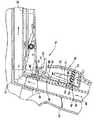
図1を参照すると、手動式材料塗布装置10がノズル部12と、バレル部14と、ハンドグリップ部16とを含み得る。本明細書中のいくつかの例では、装置10は例えば任意の適した材料塗布装置又はスプレーガンであってもよい。スプレーガン及び材料塗布装置という用語は本明細書中で交換可能に使用されるが、材料塗布装置はスプレーガンだけでなく、それ以外の多くの形態で実現されることができ、その術語に限定されないことを理解されたい。典型的には、ノズル部12、バレル部14、及びハンドグリップ部16はそれぞれ、多部品アセンブリであり、互いから分離可能でもある。しかしながら、本明細書中の本開示及び本発明は、材料塗布装置10又はその構成部品のいかなる特定の設計、形状、又は構成(ハンドグリップ部16の設計、形状、若しくは構成を含む)に限定されず、加工部品、成形部品、それらの組合せ、一体部分等を含み得る。本明細書中の一部の記載では、材料塗布装置の本体又は装置の本体を全体的に参照することができ、これは、例えばハンドグリップ部16、バレル部14、及びノズル部12等、塗布装置の構造のいくつかの部分又は全てを形成する任意の部品又は部品の組合せを参照することを意味する。種々の発明及び本開示の発明の態様は、本明細書において明記及び開示するために、非常に多数の方法、並びにハンドグリップ部16、バレル部14及びノズル部12の構成で、実現することができる。 Referring to FIG. 1, the manual
ハンドグリップ部16は、例えば、スプレーガン10の動作中に手で保持するか又は把持されるハンドル18の形態で実施することができる。静電装置10の場合、ハンドル18は操作者の手と接触すると共にアースする部分を含み得る。この記載の目的のため、ハンドグリップという用語は全体的に、塗布装置10の動作中に操作者が手で保持するか又は把持して当該装置10を支持及び制御する任意の構造又はアセンブリ又は部材を指すのに用いられ、ハンドル、グリップ、又は他の構造体は、このようなハンドグリップの例示的な実施形態である。 The
図1に示すように、コーティング材料供給部20をスプレーガン10へのコーティング材料源として用いることができる。給送又は供給ホース22を一般的に使用してスプレーガン10を供給部20と接続する。ホースコネクタ24を設けて供給ホース22をスプレーガンに固定取付けしてもよい。図1に示すような静電スプレーガンの場合では、静電制御ケーブル又は接続部26をスプレーガンの制御システム28と電気入力部30との間に設けてもよい。制御システム28はまた、例えば、操作者が第1の手動式装置32を作動させたことを示すトリガ起動信号等の1つ又は複数の信号をスプレーガン10から受信してもよい。例示的な実施形態では、第1の手動式装置を、例えば主トリガ又はスイッチ32の形態で実現してコーティング動作を開始させてもよい。主トリガ32は、操作者がハンドグリップ部16によってスプレーガン10を保持するのに使用しているのと同じ手の指を用いてトリガ32を作動させることができるように設計されてもよい。「主」トリガとは単に、第1のトリガ32に関係付けられるが必ずしも唯一の機能である必要はない主機能(primary function:一次機能)がコーティング動作のためにスプレーガンの動作をオン/オフに制御するものであることを意味する。主トリガ32が作動すると、電気信号又は電気状態(例えば閉接点)が制御システム28に送られるか又は制御システム28によって検出されて、スプレーガン10にコーティング材料流を流し始め、他の信号が生成されて、スプレーガン用の電力を起こしてもよい(例えば静電動作の場合)。例示的な実施形態では、主トリガ32の作動に関係付けられる電気信号又は電気状態がディスプレイコントローラ110(ここでは図4を参照)と接続し、ディスプレイコントローラ110によって最初に検出される。このことは本明細書においてより詳細に以下に説明する。ディスプレイコントローラ110は、ネットワークを介して制御システム28と通信し、それによって、制御システム28がディスプレイコントローラ及びネットワークを介して主トリガ32の作動を検出する。代替的に、主トリガ32の作動を、ネットワークを介さない場合は、例えば、主トリガ32と制御システム28とを直接、有線又は無線接続することによって、制御システム28に結合することができる。 As shown in FIG. 1, the coating
スプレーガン10と制御システム28又は他のシステムコンポーネントとの間の電気信号又は電気状態は全て、電気ケーブル26を介して電線に沿って送信することができる。代替的に、信号をRF、IR光学等を含む無線技法を用いて送信してもよい。材料塗布装置10を制御システム28につなぐのにネットワークを使用することを含む、本明細書における実施形態では、ネットワーク配線(単線又は多線)を電気ケーブル26に通すこともできる。 Any electrical signal or electrical condition between the
制御システム28は、当該技術分野において既知のように、スプレーガンの電力要件の入力電力及び動作を制御すると共に、コーティング材料供給部20、パージ供給部34、及び他のシステム関連特徴部(スプレーブース、部品コンベヤ等(図示せず))の動作を制御するのに適した任意の構成とすることができる。材料供給部20は、本明細書に記載されている装置と方法とを組み合わせて用いるときを除き、本発明の一部を形成しない。コーティング材料供給部20は典型的に、制御システム28の制御下のポンプ(複数可)を含み、それによって、制御システム28は操作者によるトリガ32の作動に応答してポンプを始動させる。これによって、コーティング材料がハンドグリップ部18、バレル部14を流れ、ノズル部12から流出して、典型的には例えば粉体コーティング材料用に雲様パターンの形態の所望のスプレーパターンSを形成する。 The
制御システム28の制御下のパージ供給部34を用いて、加圧したパージ空気又は他のガスをパージホース36を介してスプレーガン10に供給してもよい。パージホース36はハンドグリップ16に配置されている適したホースコネクタ入力部(input:入口部)38、この例ではハンドル18のベース40に接続可能とすることができる。そのため、ハンドグリップ16へのパージ空気入口は、ホースコネクタ24のコーティング材料入力部とは別個とすることで、パージ空気が、まずハンドグリップ16内のパージ空気流路を通過することによって、最初にコーティング材料流路(図1には図示せず)に入るようにすることができる。しかしながら、本発明はいかなる特定のパージ構成又はコーティング材料流路構成にも限定されない。例えば、パージ空気はいくつか例を挙げると、代替的に、供給部20付近若しくは供給部20における、又はさらにはバレル部の近く若しくはノズル部12の近くのコーティング材料流路に導入されてもよい。本発明はまた、ハンドルのベース40から延びるコーティング材料流路に限定されない。多くのガン設計では、材料流路はまず、例えばガンのバレル部まで入る。 The
図2は、塗布装置10を長手方向断面図で示す。図示のように、ハンドル18は、長引く動作又は方向転換(shifts)の際に操作者の手にかかる負担を軽くするために人間工学的に形を変えることができる。コーティング材料ホースコネクタ24は、供給ホース22(図示せず)の一端を受け取るようになっている第1の端42と、入口管48の第1の端46に伸縮自在に(telescopically:入れ子式に)摺動する対向する端44とを有する。 FIG. 2 shows the
入口管48は、ハンドル18内を延び、例えば伸縮自在な接続部等、エルボアダプタ50の一端と嵌合する。エルボアダプタ50は、例えば伸縮自在な接続部等、出口管52の第1の端と嵌合する別の端を有する。出口管52はバレル部14に沿ってノズル部12に延びており、そのため、コーティング材料が出口管の遠位端を通って流出してノズル部12に入り、ノズル部12からスプレーパターンSを形成する。ノズル部12の詳細は本開示の発明を理解して実施するのに必要とされない。代替的な設計では、例えば、出口管52自体が出口オリフィスを形成するか又は提供し、その出口オリフィスを通ってコーティング材料がノズルから出る。本明細書中の例示的な実施形態では、ノズル部12は電極アセンブリ54を含んでいてもよく、この電極アセンブリ54はバレル14の後部の内部電源部56によって帯電される。電源56は典型的に、既知のような高電圧乗算器及び関連回路の形態で実現される。ノズル部12の外側に位置付けられる電極チップを含む、多くの異なるタイプの電極アセンブリ、及び外部電源と、スプレーガン10の外部の電源の部分とスプレーガン10の内部の他の部分のハイブリッド設計とを含む、多くの異なるタイプの電源設計、構成、及び配置を用いることができる。加圧空気源に接続可能な電極空気洗浄入口(electrode air wash inlet)58に空気路(図示せず)を設けてもよく、この空気路はハンドル18を通ってバレル部14に沿ってノズル部12に延びているため、ノズルの先端にわたって空気流を供給してノズルの先端にコーティング材料が蓄積しないようにするのに役立つ。 The
したがって、入口管48、エルボ50、及び出口管52は組み合わさってコーティング材料流路を形成又は画定し、例示的な実施形態では、コーティング材料流路は入口管48、エルボ50、及び出口管52の内部容積によって形成され(且つ、符号60を付されている矢印で表されるように)、ハンドル18からバレル部14に沿ってノズル部12に延びる。 Thus, the
本開示の発明の態様によれば、第2の手動式機構70が提供され得る。この第2の手動式機構70は、例えば第2のトリガ若しくはスイッチ、又は補助トリガ若しくはスイッチの形態で実施され得る。好ましくは、補助トリガ70は指で作動させることができ、特に、スプレーガンのハンドル18も保持している操作者の手の指で作動させることができるが、必ずしもそうである必要はない。必須ではないが、別の数本の指を用いて第1のトリガ32及び第2のトリガ70を作動させることができる。 According to inventive aspects of the present disclosure, a second
図3、図9A、及び図9Bを参照すると、主トリガ32及び補助トリガ70がメンブレンスイッチ又は他の適したスイッチ設計部を作動させるように動作可能に連結されることができる。この例での主トリガ32は、一対の可撓性アーム74が延びている主トリガ本体72を有する。各可撓性アーム74の遠位端76が、メンブレンスイッチ80の対向する両側の位置76a及び76b等、主トリガ32に関連付けられるメンブレンスイッチ80付近で、メンブレンスイッチアセンブリ78の一方の側と係合する。遠位端76は代替的に、主トリガ本体72をハンドル18側へ引いて主トリガ32を作動させると、脚部74が内方に押されることができるように十分に支持を行う好都合に利用可能な任意の他の表面と係合してもよい。 Referring to FIGS. 3, 9A, and 9B, the
この例では、メンブレンスイッチアセンブリ78は3つのメンブレンスイッチ80、96、及び98を有する。下部のスイッチ80を用いて主トリガ32の作動を検出することができ、上部の2つのスイッチ96及び98を用いて補助トリガ70の作動を検出することができる(本明細書において以下にさらに説明する)。種々のメンブレンスイッチはボード78aに配置することができるが、所望に応じて、任意の他の好都合な方法でスプレーガン内に設けてもよい。 In this example, the
主トリガ本体72は、より軟らかな作動支柱75を受け入れて保持する内向き中空ボス73をさらに含み得る。作動支柱75は、ボス73の内側に十分に挿入されると端部75aがボス73の端からわずかにはみ出るようなサイズである。端部75aは、主トリガ本体72を操作者が引くと、関係付けられているメンブレンスイッチ80と係合してスイッチ80を作動させる。主トリガ本体72は、ハンドル18のピボット支柱(pivot posts)77a(図9Aには1つしか図示せず)及び主トリガ本体72の協働する穴77b等、任意の好都合な手段によって、ハンドル18に取り付けることができる。支柱77aを用いて補助トリガ70をハンドル18上に支持することもできる。主トリガ本体72は窓79をさらに含んでもよく、組み立て後、補助トリガ70がこの窓79から延びる。このようにして、操作者は所望であれば1本の指でトリガ32及び70の双方に容易にアクセスすることができる。 The
トリガ32を内方に(図3及び図9Aで見ると左方に)引くと、作動支柱75の遠位端75aがメンブレンスイッチ80の可撓性接触部80aに押し当たり、これによって固定接触部82(図3)と電気接触する。この電気接触又は電気接続は制御システム28にコーティング動作を開始する指示を与える。トリガ32を操作者が解放すると、可撓性アーム74のばね様付勢によってトリガ本体72が図3に示すその非作動位置に押し戻り、支柱75がスイッチ80から十分遠くに後退することで、可撓性接触部80aが跳ね返るか又は固定接触部82から離れて接触しなくなり、それによって、制御システム28にコーティング動作を停止するように信号を送る。主トリガ32が解放されると、支柱75は、必須ではないが、可撓性接触部80aと事実上接触状態のままとなり得る。 When the
支柱75の使用は多くの利点を有する。好ましくは、支柱は、例えばゴム等のより軟らかい材料から作製することができるため、操作者はより快適さにかなった軟らかな触覚反応を受ける。支柱の相対的な硬さ又は軟らかさを単に変えることによって感触を変えることができる。ゴム材料等の軟らかい支柱75の使用によって、トリガ32に加えられる過移動又は過剰力に起因する、スイッチ80に対する損傷を軽減するように支柱75が押し当たることも可能となる。2つの可撓性アーム74の使用は代理機能性を与える。これらのアームのうち一方が損傷又は破損した場合、他方のアームがなおもトリガ32を機能させ、特に、トリガ32が解放されたときに確実にスイッチ80が開くようにする。 The use of
この実施形態における補助トリガ70は二重切替え機構とすることができ、その場合、補助トリガ70は図3に示す中立位置又は非作動位置、第1の作動位置、及び第2の作動位置を有する。しかしながら、本発明は特定のトリガ構成にも単一の補助トリガにも限定されない。補助トリガは3つ以上の作動位置を有していてもよいか、又は2つ以上のこのような補助トリガがあってもよい。一例として、手動式機構70は、複数の位置を有するスライドスイッチ又は複数の位置を有する回転スイッチ、又は複数の位置を有する操作レバー等であってもよい。いずれの場合も、補助トリガ/スイッチ70の設計は、操作者によるこのような装置の使用によって行われる全体的機能性によって確定される。 The
補助トリガ70は、中央ハブ86から延びる指掛けレバー84を含み得る。ハブ86は、通常、トリガ70を中立位置に付勢するばね又は他の機構(図示せず)であってもよく、このことは、関連スイッチを作動させるのにトリガ70に力を加える必要があることを意味する。ハブ86からは第1の作動アーム88及び第2の作動アーム90が延び、これらは、必須ではないが、トリガ70が中立位置にあるときに、上部メンブレンスイッチ96及び下部メンブレンスイッチ98それぞれの可撓性接触部92及び94それぞれと係合することができる。したがって、補助トリガ70が図3で見た場合に上方に枢動すると、第1の作動アーム88がその関係付けられている可撓性接触部92に押し当たって上部メンブレンスイッチ96を閉じる。同様に、トリガ70が図3で見た場合に下方に枢動すると、第2の作動アーム90がその関係付けられている可撓性接触部94に押し当たって下部のメンブレンスイッチ98を閉じる。主トリガ32も作動している間又は作動していないときに、操作者は補助トリガ70を容易に作動させることができることに留意されたい。メンブレンスイッチ96、98は、作動すると制御システムに所望の操作又は機能が行われるべきであることを指示する。主トリガスイッチ80の場合のように、補助トリガスイッチ96、98についての対応する電気信号又は電気状態がディスプレイコントローラ110及びネットワーク112(図1)を介して制御システム28にやりとりされる。代替的に、これらの信号は無線式又は電気ケーブル26に沿った線を通じてやりとりされてもよい。 The
例えば、制御システム28は、ソフトウェア又は他の方法等での指示(補助トリガ70の上/下作動はコーティング動作パラメータをインクリメント又はデクリメントする命令に関連する)を含み得る。代替的に、補助トリガの作動を用いて、1つ又は複数のコーティング動作パラメータを変更又は選択するのに利用可能な選択肢のリストをスクロールしてもよい。多くの他の代替的な機能及び制御を補助トリガ70の作動に関係付けることができるが、非常に多くあるため、ここでは列挙しない。さらに、補助トリガ70の機能性によってスプレーガン10又はシステムの種々の異なる動作モードに対して変更を行ってもよい。例えば、コーティング動作中、補助トリガ70の作動によって材料流量を増減してもよいが、パージ動作中はトリガを用いてシャットダウンモード又はスタンバイモードにしてもよい。付加的な特徴及び機能は本明細書において以下にさらに詳細に説明する。 For example, the
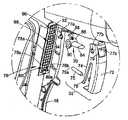
図2及び図4を参照すると、本開示の発明の別の態様によれば、ディスプレイ100等の視覚情報装置を設けて、スプレーガン10、(パージ供給部34、材料供給システム20等のような)システムコンポーネントのうち1つ又は複数についての1つ又は複数の動作パラメータ若しくは他の情報に関する情報を操作者に提示する。好ましくは、ディスプレイ100はスプレーガンに配置されるか又はスプレーガンの一部として設けられる。例示的な実施形態では、操作者がスプレーガンを使用している間に容易に見ることができるようにディスプレイ100をバレル部14の後端に設けてもよい。 2 and 4, according to another aspect of the presently disclosed invention, a visual information device such as a
ディスプレイ100は好都合には、ガン本体内に取り付けられるか、又はガン本体内の奥、この例では電源部56の真後ろに配置することができる。保護ビューイングカラー(Protective-viewing collar)102を用いることで、ディスプレイを悪影響及び汚染から保護し、おそらくは状況によって、ディスプレイがより容易に見えるであろう。保護レンズ又はカバー104をさらに設けてもよく、レンズ104は必要に応じてディスプレイ100を使用し易くするように適切な記号及び印を含んでもよい。ディスプレイ100は、例えば一対の7セグメントLED等のビジュアルインジケータ装置106と、ディスプレイコントローラ110及び関連の付加的な回路を含み得る1つ又は複数の回路基板108とをさらに含み得る。ディスプレイコントローラ110は、ディスプレイ100に対する全ての制御機能を行い、また、ネットワークインタフェースも含み得ることで、ネットワーク112(図1を参照)を介して、制御システム28に関係付けられる主コントローラ114と通信することができる。適したネットワークは、例えばLINネットワーク等の単線ネットワーク(例えば電気ケーブル26を通る単線)とすることができるが、代替的に、必要に応じて多線及び無線を含む任意のネットワークを用いてもよい。例示的な実施形態では、ディスプレイ100は、例えばプッシュボタン式メンブレンスイッチ等の1つ又は複数の手動入力部116も含み得る。しかしながら、手動入力部116は代替的に、塗布装置の他の場所に配置されてもよい。 The
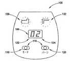
図5及び図6を参照すると、ディスプレイ100の手動入力部116は、例えば第1のプッシュボタン式メンブレンスイッチ118及び第2のプッシュボタン式メンブレンスイッチ120を含み得るが、必要に応じて任意のスイッチ又は選択装置(selector device)を用いてもよい。また、ビジュアルインジケータ装置106は第1の7セグメントLEDディスプレイ122及び第2の7セグメントLEDディスプレイ124を含み得る。この例におけるディスプレイ122及び124は数値ディスプレイであるが、操作者に表示されることが所望される情報を伝えるのに適した英数字、LCD等を含む他のディスプレイを用いてもよい。所望に応じて付加的なビジュアルインジケータを用いてもよい。例えば、LED等の第1のランプ126及び第2のランプ128を用いて、関係付けられるアイコン130及び132(図6)を照明してもよい。 5 and 6, the
一例として、手動入力部116の1つをモード選択スイッチ118として用いてもよい。他の手動入力部をパージ開始スイッチ(Purge Start switch)120として用いてもよい。パージ開始スイッチ120が作動すると、指示(indication)がネットワーク112を介して制御システム28に送信され、制御システム28がパージ動作を開始する。パージ開始スイッチ120を作動しない場合、システムは所望に応じてスタンバイ状態又はコーティング動作状態若しくは他の状態にあってもよい。パージ動作は第2の入力部120を使用する以外の他の方法で開始してもよい。例えば、制御システム28は、補助トリガ70が作動してパージ動作が開始されたことを認識するようにプログラムされてもよい。これによって、操作者が片手でコーティング動作及びパージ動作を制御することが可能となる。このような場合では、第2の入力部120はシステムシャットダウン、リセット、又は任意の他の所望の操作又は動作等の別の機能を行うようにプログラムされてもよい。 As an example, one of the
システムによっては、ディスプレイ100自体が、任意の数又はタイプのシステム関連データ及びパラメータについての情報を操作者に提示する機能性を有し得る。例えば、ディスプレイコントローラ110は、ネットワーク112を介して制御システム28から受信したデータに基き、コーティング動作中の材料流量を単に表示するようにプログラムされてもよい。材料流量は例えば、2つの例を挙げると、1分当たりのグラムで又は最大流量の百分率として表され得る。材料流量は、フローエア率等のフローエア値から推定されることもできる。 In some systems, the
しかしながら、ディスプレイ100を用いて補助トリガ70の柔軟性及び機能性を大幅に高めることができることがさらに意図される。補助トリガ70は多入力機構とすることができるため、これを用いて、何の情報を表示するかを制御すると共にオプションリストから選択を行うことができる。一例として、モード選択ボタン118を用いてディスプレイ100に対し異なる表示モードを選択することができる。一実施形態では、モードスイッチ118を押すことによって、装置が第2のアイコン132のランプ128を照明させる流量モードとなる。モードスイッチ118を再度押すと、第2のアイコン132のランプが消え、第1のアイコン130用のランプ126が照明し、これによって装置がフォルダ表示(Folder display)モードとなる。モードボタンを各連続作動させるには、ディスプレイをフォルダモードと流量モードに交互に合わせる。 However, it is further contemplated that the
フォルダ表示モードでは、操作者は次に補助トリガ70を用いて、コーティング動作のプリセットレシピのリストを上下又は前後にスクロールしてもよい。補助トリガ70の各作動はビジュアルインジケータ装置106を介して操作者に新たなプリセット数を提示する。図6の例では、ディスプレイはFolderモードにあり、プリセット数02が表示されている。操作者がディスプレイをプリセット数02のままにしておく場合、制御システム28は次いで、プリセットレシピ用の所望の動作パラメータを開始することになる。操作者は必ずしも、特定のレシピに対して全てのパラメータ及び条件がどのように調整されるかを知る必要はなく、これが要求されているレシピであること、又は特定のコーティング動作を最良に実施するレシピであることさえ分かっていればよい。任意選択的に、関連付けられている情報を実際に有するプリセット数しか操作者に表示される必要がなくてもよい。 In the folder display mode, the operator may then use the
流量モードでは、関係付けられているアイコン132が照明されることで操作者には、どのモードが使用中であるかが分かる。この例では、ビジュアルインジケータ装置106は次いで、スプレーガン10を通るコーティング材料に関する流量を表示することができる。この情報を例えば制御システム28からネットワーク112を介してディスプレイコントローラ110に送信することができる。流量モードの場合、操作者は所望に応じて補助トリガ70を上下に作動させて流量パラメータを増減させることができる。この機能性は主トリガ32とは独立しているため、操作者は、コーティング動作を実際に行いながらでも又は場合によってはコーティング動作の直前若しくは直後に、これらの選択を開始することができる。 In the flow mode, the associated
選択された動作モードに関連する情報を操作者が視覚的に見ることが可能であり、且つ、視覚オプションの点では、スプレーガン10又はコーティング中の物体から注意を逸らされるか又は目を離す必要なく、選択及び選択の視認を行うことが可能であるため、ディスプレイ100では補助トリガ70のこの機能性が大幅に高まっている。これによって、特定のコーティング動作を妨げることなく、又は少なくともスプレーガン又はコーティング領域から目を離す必要なく、1つ又は複数の動作パラメータを変更又は選択することが可能となることで、このような変更及び選択を実施すると共に行われた選択を確認することができるようにする。例えば、流量モードでは、操作者は必要に応じて単に補助トリガ70を上下に作動させてコーティング動作中の流量を調整又は選択して製品仕上げを高めることができる。或いは、操作者はコーティングすべき新たな物体がコーティング領域に入る際に、又は現在のプリセットが物体を十分にコーティングしていない場合に、プリセットレシピを切り替えてもよい。代替的に、システムは、主トリガ32が作動していないと、例えば流量又はプリセットレシピ選択又はパージ開始等の選択を可能にするようにプログラムされてもよい。さらになお、補助トリガ70の作動に関係付けられている機能及び制御は、主トリガ32が作動しているか否かに応じ、さらに、手動入力部116を介して何のモードが選択されているかに応じ得る。例えば、主トリガ32が作動していれば、補助トリガはパージ動作を開始することができないであろう。 Information related to the selected mode of operation can be viewed visually by the operator, and in terms of visual options, it is necessary to be distracted or look away from the
したがって、補助トリガ70とディスプレイ100とを組み合わせた機能性によって、行われた選択を確認するのにスプレーガン又はコーティング領域から目を離す必要が全くなく、操作者が所望であれば片手を用いて、しかも、スプレーガンを支持又は把持するのに使用しているのと同じ手を用いて1つ又は複数の動作パラメータの選択を含むコーティング動作を制御することが可能になる。 Thus, the combined functionality of the
ディスプレイ100又は補助トリガ70に対してプログラムされ得る機能及びパラメータ選択を限定する必要はない。任意の機能性及びパラメータ選択は特定のシステムに対する必要に応じて利用可能にすることができる。また、付加的な補助トリガ又は多位置(multi-position)手動式機構を使用することによって、本明細書に記載の概念全体の柔軟性がさらに増す。別の例として、補助トリガ70の連続作動を用いてオプションのステップに進む(step)か、又は1つ又は複数のコーティング動作パラメータ、例えば流量の増分変化のステップに進んでもよいが、トリガを停止状態のままにする場合、値は例えばより大きなステップ又は速いステップでインクリメントし得る。 There is no need to limit the functions and parameter selections that can be programmed for the
制御システム28はまた、例えばシステムのセットアップ、較正等の間に用いることができる主ディスプレイ又はシステムディスプレイ140(図1)を含み得る。しかしながら、このディスプレイ140は操作者の動作領域の近くに位置していても位置していなくてもよいか、又はコーティング動作中に操作者に見えなくてもよい。ディスプレイ100を取り付けたガンが、システムのディスプレイ140の後部に提示されるのと同じ情報の一部又は全てを提示してもよい。 The
代替的な機能性のほんのいくつかの例を挙げると、制御システム28及びガンコントローラ110の場合に適当な設定及びプログラミングによって、補助トリガ70を用いて、帯電圧の増減の調整、電流限界の増減の調整、システム内の全てのガン(マスタとして手動ガンを用いる自動ガンを含む)プリセットの調整を行い、且つ、パージ動作又は色替え動作を開始することができる。色替え動作は、例えば供給部変更、種々のパージ動作、スプレーブース洗浄動作、オーバースプレー回収動作、ガン発射(gun blow off)等の動作及び機能を含み得る。 To name just a few examples of alternative functionality, the
これらは、補助トリガ70に割り当てられ得る多くのプログラム可能な又は選択可能な機能のうちのいくつかにすぎない。付加的なオプションがディスプレイ100にある手動入力部116に利用可能である。例えば、これらの手動入力部は、プリセットレシピ選択、開始パージ動作、作動停止(disable)ボタン、自動ガントリガ、及び多重流量制御モード等、入力部に割り当てられると共にプログラムされる機能性を有し得る。流量制御に対して、2つの利用可能且つ例示的なオプションは、手動入力部116のうち1つを用いて初期(traditional)流量制御モード又は総流量制御調整モードの選択肢を提示することである。初期流量制御モードでは、補助トリガ70を用いて、互いに独立してフローエア設定又は霧化エア設定を調整してもよい。例えば、1つの入力部116のモードでは、補助トリガ70を用いてフローエアを調整してもよく、選択された別の入力部116のモードでは、補助トリガ70を用いて霧化エアを調整してもよい。総流量制御モードでは、操作者は主コントローラ114に対する入力機能を介して総空気流量設定を選択してもよい(か、又は代替的に、例えば総空気流量がプリセットレシピ選択の一部として選択されることができる)。例えば総空気流量パラメータを用いてノズル部12からのコーティング材料の速度を選択してもよい。次いで、操作者は補助スイッチ70を用いてフローエア及び霧化エアとなる総空気流の百分率又は比率を選択して所望のコーティング材料速度、流量、及び/又は膜堆積を達成することができる。例えば比率を調整することは、速度パラメータを変更するのではなく、スプレーガン10から生成されるコーティング材料雲中の粉体量を変えることである。次いで、制御システム28は、総エアフロー及び選択比の選択された2つの入力値に基づいて適切な噴霧エア値及びフローエア値を設定する。 These are just some of the many programmable or selectable functions that can be assigned to the
本明細書でのパラメータ及び値の参照は限定的な意味で解釈されるべきではないことに留意されたい。選択されたパラメータ及び値は、実験的又は予測された分析に基づいた実際のデータ点とすることができるが、実際のデータ点を表すのではなく、性能、効果、及び結果に関するコーティング動作パラメータを表す数、値又は他のデータ若しくは情報とすることもできる。例えば、プリセットレシピ数を、操作者によって選択可能なパラメータ又は値として考慮することができるが、実際には、コーティング動作に関する1つ又は複数の設定、値等を表しているにすぎないか又はコード化しているにすぎない。別の例として、ディスプレイ100上で操作者に提示される流量情報は、測定した場合の実際の流量値であってもよいか、又はその代わりに、総流量の0%〜100%の等のスケールとして確定されてもよい。したがって、本開示は、ディスプレイ100を介して操作者に提示されると共に手動入力部116及び補助トリガ70を介して選択されるコーティング動作パラメータの選択肢及び選択又は他の情報の任意の特定フォーマット若しくはコード又は表示を必要とするものとして解釈されるべきではない。 Note that references to parameters and values herein should not be construed in a limiting sense. The selected parameters and values can be actual data points based on experimental or predicted analysis, but do not represent actual data points, but rather represent coating operating parameters related to performance, effectiveness, and results. It can also be a number, value or other data or information represented. For example, the number of preset recipes can be considered as a parameter or value that can be selected by the operator, but in actuality it merely represents one or more settings, values, etc. relating to the coating operation or code It is only becoming. As another example, the flow information presented to the operator on the
手動入力部116が異なる機能性に対して選択される場合、アイコン130及び132も、機能性を操作者に合わせる(identify)ために適宜変更されてもよいことに留意されたい。例えば、単純なオーバーレイを用いて、ランプ126及び128によって照明されるアイコン図柄(figure)を変更してもよい。 Note that if the
さらになお、例示的な実施形態又は他の実施形態では、システムの主コントローラ114は、ネットワーク112又は他の適した通信リンクを介して、スプレーガンに取り付けられたディスプレイコントローラ110と通信する。このような場合、主コントローラ114は、改訂レベル(revision level)又は他のソフトウェア、及びディスプレイコントローラ110が使用中であるというデータベース情報を認識するようにプログラムされてもよく、必要に応じて例えば、ディスプレイコントローラ110に対するアップロード更新、又は特定の用途及び構成に必要とされ得る異なるプログラムの更新若しくはアップロード等、様々なプログラミング機能を行ってもよい。 Still further, in the exemplary or other embodiments, the
図7を参照すると、ディスプレイコントローラ110及び関連回路の例示的な実施形態が示されている。ディスプレイコントローラ110は例えばDSP回路、又は他のマイクロコントローラ、マイクロプロセッサ、離散回路等のような任意の適したコントローラとすることができる。好ましくは、ディスプレイコントローラ110は、適当なメモリ及び他の周辺サポート回路と共に、プログラム可能な回路の技術分野において一般的によく知られているようなソフトウェアを介してプログラム可能である。ディスプレイコントローラ110は回路基板108(図4)の1つに配置されてもよく、LED及びディスプレイドライバ回路142との適当な接続部を含む。ディスプレイ及びドライバ回路142はまた、入力として手動入力部118及び120への接続部を受け得る。ディスプレイコントローラ110は、主トリガスイッチ78(図3)並びに補助トリガスイッチ96及び98からの入力を受け取ることができる。ディスプレイコントローラ110はまた、配線束144を介して制御システム28の主コントローラ114との通信を提供する(例えば、ネットワーク114のインタフェースがディスプレイコントローラ110のソフトウェア及び回路内に設けられてもよく、主コントローラ114はまた、ディスプレイコントローラ110と通信するのに必要なネットワークインタフェースの機能性に組み込まれていてもよい)。 Referring to FIG. 7, an exemplary embodiment of the
図8を参照すると、制御システム28の一実施形態では、主コントローラ114は例えば、DSPタイプのコントローラ、マイクロコントローラ、マイクロプロセッサ、離散回路等の任意の適した装置とすることができ、既知の又は今後開発されるソフトウェア、ハードウェア、及びファームウェアのプログラミングを用いて、制御システム28の種々の機能及び制御を実施してもよい。主コントローラ114は、制御システム28に付随するスプレーガンに駆動信号を提供するガンドライバ回路(Gun Driver Circuit)146及びDC源148とインタフェースしてもよい。この実施形態では、DC源148を用いて、スプレーガン用のPWM駆動信号を励起する。主コントローラはまた、ディスプレイコントローラ110と通信するために、ネットワーク112とインタフェースする。主コントローラ114はまた、システムディスプレイ140(図1)のために、シリアル周辺インタフェース回路150aを介してディスプレイドライバ回路150とインタフェースする。スプレーガンのディスプレイ100は、主システムディスプレイ140に提示されているような一部若しくは全て又は異なる表示情報を受信し得る。例えば、流量を、選択されたプリセット数と共に双方のディスプレイ上に表示してもよい。双方のディスプレイ上に同時にどの程度の共通情報が提示されるかは設計選択肢の問題である。スプレーガンのディスプレイに表示され得る付加的な情報としては、種々の警告、アラーム等が挙げられ得る。 Referring to FIG. 8, in one embodiment of the
主コントローラ114はまた、既知のように、多ガン及び通信ネットワークが相互接続する他の機器を用いるシステムのために、例えばCANネットワーク等のネットワーク152とインタフェースすることができる。他のインタフェースとして、操作者がコントローラ114に対して入力を行うことを可能にするキーパッド又は入力ノブ156等の外部入力部を含み得る。例えば、レシピプリセット、又は特定のプリセット(複数可)に割り当てられている1つ又は複数の個々のパラメータ及び制御を調整するように所望されてもよい。外部入力部156によって電圧及び電流過渡が生じるため、必要に応じて過渡電圧抑制回路158が使用されてもよい。構成可能な(プログラム可能又は選択可能であるような)補助外部入力部160は、例えば、コンベヤ制御、自動ガントリガ制御、発射検出信号等を含み得る。これらの入力は、フィールド配線ノイズ(field wiring noise)を含む可能性があり、過渡スパイクが発生するため、例えば、このような影響から主コントローラ114を保護するオプトアイソレータ等の信号調整回路162を使用することが望ましいであろう。主コントローラ114はまた、所望に応じてバイブレータをオン/オフにするようにリレー回路164を介して振動ボックスフィーダ(vibratory box feeder)とインタフェースしてもよい。さらになお、DIPスイッチ166等の構成スイッチを、制御システム28の外部構成選択、及びオプションの外部プログラミングインタフェース168に用いてもよい。特定のシステム、特に、手動ガン及び自動ガン、高度スプレーブース、粉体回収及びガン移動機(gun mover)設計等を含む、より複雑なシステムの必要に応じて、多くの他の又は代替的なインタフェース、並びに制御及び構成のオプションを用いてもよい。 The
本発明は例示的な実施形態を参照して説明している。本明細書及び図面を読んで理解すれば、変更形態及び代替形態が当業者には容易に想起されるであろう。添付の特許請求の範囲又はその均等物内にある限り、このような全ての変更形態及び代替形態を含むことが意図される。 The invention has been described with reference to exemplary embodiments. Modifications and alternatives will readily occur to those skilled in the art upon reading and understanding this specification and the drawings. It is intended to include all such modifications and alternatives as long as they fall within the scope of the appended claims or their equivalents.
Claims (14)
Translated fromJapaneseコーティング動作中に操作者が手で把持するハンドル(16)と、
前記ハンドル(16)に配置される第1の手動式機構(device)(32)であって、第1の位置ではノズル(12)からのコーティング材料の流れを開始し、第2の位置では該ノズル(12)からのコーティング材料の流れを停止する、第1の手動式機構(32)と、
該装置に配置される数値ディスプレイ(100)と、
該装置に配置される第2の手動式機構(70)とを備え、
前記第2の手動式機構(70)の作動によって、前記ディスプレイ(100)上に表示される情報が変更され、前記第2の手動式機構(70)は、前記ディスプレイ(100)上に表示される2つ以上の機能間で選択を行うように動作可能であり、
該装置は、さらに、該装置に配置される手動式入力部(116)を備え、前記第2の手動式機構(70)は、前記手動式入力部(116)によって選択される機能に関連するデータ(106)を変更するように動作可能であり、
前記第1の手動式機構(32)は第1のトリガ(32)であり、前記第2の手動式機構(70)は第2のトリガ(70)である、
コーティング材料塗布装置。A coating material application device,
A handle (16) held by the operator's hand during the coating operation;
A first manually-operated device (32) disposed on the handle (16), which initiates the flow of coating material from the nozzle (12) in a first position and in a second position; A first manual mechanism (32) for stopping the flow of coating material from the nozzle (12);
A numerical display (100) disposed in the apparatus;
A second manual mechanism (70) disposed in the apparatus,
By operation of said second manually actuated device(7 0), the information displayed on said display (100) is changed, said second manually actuated device(70) is displayed on the display (100) onRi operatively der to select between two or more functions,
The device further comprises a manual input (116) disposed on the device, wherein the second manual mechanism (70) is associated with a function selected by the manual input (116). Operable to change data (106);
The first manual mechanism (32) is a first trigger (32) and the second manual mechanism (70) is a second trigger (70);
Coating material applicator.
コーティング動作中に操作者が手で把持するハンドル(16)と、
前記ハンドル(16)に配置される第1の手動式機構(32)であって、第1の位置ではノズル(12)からのコーティング材料の流れを開始し、第2の位置では該ノズル(12)からのコーティング材料の流れを停止する、第1の手動式機構(32)と、
該装置に配置されるディスプレイ(100)であって、表示される機能を表す1つ又は複数のインジケータ(130、132)と、表示される前記機能に関連するデータを表示するビジュアルインジケータ装置(106)とを含む、ディスプレイ(100)と、
該装置に配置される第2の手動式機構(70)と、
を備え、前記第2の手動式機構(70)の作動によって前記ディスプレイ(100)上に表示される情報が変更され、前記第2の手動式機構(70)は、前記ディスプレイ(100)上に表示される2つ以上の機能間で選択を行うように動作可能であり、
該装置は、さらに、該装置に配置される手動式入力部(116)を備え、前記第2の手動式機構(70)は、前記手動式入力部(116)によって選択される機能に関連するデータ(106)を変更するように動作可能であり、
前記手動式入力部(116)は、前記ディスプレイ上に表示される流量機能を選択するように動作可能であり、前記第2の手動式機構(70)は、該装置を通るコーティング材料の流量を選択値まで増減するように動作可能であると共に、前記ディスプレイ(100)上に表示される前記データを変更して前記流量の選択値を表すように動作可能である、
コーティング材料塗布装置。A coating material application device,
A handle (16) held by the operator's hand during the coating operation;
A first manually operated mechanism (32) disposed on the handle (16), which starts the flow of coating material from the nozzle (12) in a first position and the nozzle (12) in a second position. A first manual mechanism (32) that stops the flow of coating material from
A display (100) disposed on the device, one or more indicators (130, 132) representing the function to be displayed and a visual indicator device (106) displaying data relating to the function to be displayed. A display (100) including:
A second manual mechanism (70) disposed in the apparatus;
The provided information displayed on said display (100) by operation of said second manually actuated device(7 0) is changed, said second manually actuated device(70), said display (100) on operatively der to select between two or more functions to be displayed onis,
The device further comprises a manual input (116) disposed on the device, wherein the second manual mechanism (70) is associated with a function selected by the manual input (116). Operable to change data (106);
The manual input (116) is operable to select a flow function displayed on the display, and the second manual mechanism (70) controls the flow of coating material through the device. Operable to increase or decrease to a selected value and operable to change the data displayed on the display (100) to represent the selected value of the flow rate,
Coating material applicator.
材料塗布装置(device)(10)に配置されるディスプレイ(100)上に、該ディスプレイ(100)上に表示される機能の表示(indication)(130、132)及び該機能に関連するデータ(106)を操作者に表示するステップと、
前記装置に配置されている手動式機構(70)と手動式入力部(116)を動作させることによって、前記ディスプレイ(100)上の情報を変更するステップとを含み、前記情報を変更するステップ中、前記手動式入力部(116)は前記ディスプレイ(100)上に表示される2つ以上の機能間で選択を行うように動作し、前記情報を変更するステップ中、前記手動式機構(70)は、前記ディスプレイ(100)上に表示される、前記手動式入力部(116)によって選択された機能に関連する前記データ(106)を変更するように動作し、前記手動式機構(70)と前記手動式入力部(116)はスプレーガン上に配置される、コーティング動作を制御する方法であって、
前記情報を変更するステップ中、前記手動式入力部(116)は流量機能を選択するように動作し、前記手動式機構(70)は前記装置(10)を通るコーティング材料の流量を選択値まで増減するよう動作すると共に、前記ディスプレイ(100)上に表示される前記データを前記選択値に変更するように動作する、コーティング動作を制御する方法。A method for controlling a coating operation,
On a display (100) disposed on a material application device (10),indications of functions(130, 132) displayed on the display (100) and data related to the functions (106)) To the operator,
Changing the information on the display (100) by operating a manual mechanism (70) disposed in the device and a manual input (116), during the step of changing the information The manual input unit (116) operates to select between two or more functions displayed on the display (100), and during the step of changing theinformation , the manual mechanism (70) Operates to change the data (106) associated with the function selected by the manual input (116) displayed on the display (100), and the manual mechanism (70) The manual input unit (116) is disposed on a spray gun for controlling the coating operation,
During the step of changing the information, the manual input (116) operates to select a flow function, and the manual mechanism (70) causes the flow of coating material through the device (10) to a selected value. A method of controlling a coating operation that operates to increase or decrease and to operate to change the data displayed on the display (100) to the selected value .
Applications Claiming Priority (3)
| Application Number | Priority Date | Filing Date | Title |
|---|---|---|---|
| US11/981,043US8037844B2 (en) | 2007-10-31 | 2007-10-31 | Spray gun having display and control members on gun |
| US11/981,118US8584973B2 (en) | 2007-10-31 | 2007-10-31 | Powder coating gun with manually operated controls on gun |
| US11/981043 | 2007-10-31 |
Publications (2)
| Publication Number | Publication Date |
|---|---|
| JP2009136860A JP2009136860A (en) | 2009-06-25 |
| JP5714794B2true JP5714794B2 (en) | 2015-05-07 |
Family
ID=41066285
Family Applications (2)
| Application Number | Title | Priority Date | Filing Date |
|---|---|---|---|
| JP2008280664AActiveJP5714795B2 (en) | 2007-10-31 | 2008-10-31 | Coating material spray gun |
| JP2008280652AActiveJP5714794B2 (en) | 2007-10-31 | 2008-10-31 | Spray gun having display and control member |
Family Applications Before (1)
| Application Number | Title | Priority Date | Filing Date |
|---|---|---|---|
| JP2008280664AActiveJP5714795B2 (en) | 2007-10-31 | 2008-10-31 | Coating material spray gun |
Country Status (5)
| Country | Link |
|---|---|
| US (6) | US8037844B2 (en) |
| EP (3) | EP2055392B2 (en) |
| JP (2) | JP5714795B2 (en) |
| CN (3) | CN101422760B (en) |
| CA (2) | CA2642079A1 (en) |
Cited By (1)
| Publication number | Priority date | Publication date | Assignee | Title |
|---|---|---|---|---|
| KR20170110513A (en)* | 2016-03-21 | 2017-10-11 | 엑셀 인더스트리스 | Manual coating gun and coating station comprising such a gun |
Families Citing this family (72)
| Publication number | Priority date | Publication date | Assignee | Title |
|---|---|---|---|---|
| US8037844B2 (en)* | 2007-10-31 | 2011-10-18 | Nordson Corporation | Spray gun having display and control members on gun |
| FR2935106B1 (en) | 2008-08-22 | 2010-09-17 | Pellenc Sa | PORTABLE ELECTROPORTATIVE TOOL |
| EP2547456B1 (en)* | 2010-03-18 | 2017-09-27 | Graco Minnesota Inc. | Adjusting pump flow at tool |
| EP2433716A1 (en) | 2010-09-22 | 2012-03-28 | Hexagon Technology Center GmbH | Surface spraying device with a nozzle control mechanism and a corresponding method |
| CN201841081U (en)* | 2010-09-28 | 2011-05-25 | 潘星钢 | Spray gun with air pressure display device |
| DE102010060086A1 (en)* | 2010-10-20 | 2012-04-26 | Sata Gmbh & Co. Kg | Paint application system and method for its operation |
| DE102011004024A1 (en)* | 2011-02-14 | 2012-08-16 | Illinois Tool Works Inc. | Control device for a powder spray coating device |
| CN102896101B (en) | 2011-07-26 | 2015-12-09 | 苏州宝时得电动工具有限公司 | Portable Cleaning Equipment |
| US20130075489A1 (en)* | 2011-09-27 | 2013-03-28 | Shiqi Zhu | Pneumatic spray gun with digital pressure readout |
| EP2641661B1 (en)* | 2012-03-20 | 2016-05-11 | Hexagon Technology Center GmbH | Graphical application system |
| JP5967647B2 (en)* | 2012-07-13 | 2016-08-10 | アネスト岩田株式会社 | Electrostatic coating air spray gun, electrostatic coating system and electrostatic coating method |
| US20140057055A1 (en)* | 2012-08-23 | 2014-02-27 | Finishing Brands Holdings Inc. | System and Method for Using an Electrostatic Tool |
| US20140084075A1 (en)* | 2012-09-21 | 2014-03-27 | Akron Brass Company | Nozzle fluid flow indicator system |
| EP2897866B1 (en) | 2012-09-24 | 2021-08-04 | Signode International IP Holdings LLC | Strapping device having a pivotable rocker |
| US10331227B2 (en)* | 2012-11-27 | 2019-06-25 | Symbol Technologies, Llc | Input device on trigger mechanism for mobile device |
| JP2014136177A (en)* | 2013-01-15 | 2014-07-28 | Anest Iwata Corp | Spray gun for electrostatic coating |
| USD736887S1 (en)* | 2013-03-14 | 2015-08-18 | J. Wagner Ag | Spray gun for paints and finishes |
| USD745635S1 (en) | 2013-03-14 | 2015-12-15 | J. Wagner Ag | Spray gun nozzle |
| CN104066263A (en)* | 2013-03-20 | 2014-09-24 | 鸿富锦精密电子(天津)有限公司 | Electrostatic gun |
| DE102013205362A1 (en)* | 2013-03-26 | 2014-10-02 | Gema Switzerland Gmbh | Spray coating gun for spray coating objects with coating powder |
| FR3004127B1 (en)* | 2013-04-09 | 2020-05-01 | Sames Kremlin | INSTALLATION FOR ELECTROSTATIC PROJECTION OF COATING PRODUCT AND METHOD FOR CONTROLLING A POWER SUPPLY GENERATOR FROM A HIGH VOLTAGE UNIT IN SUCH AN INSTALLATION |
| US9399232B2 (en)* | 2013-04-17 | 2016-07-26 | Carlisle Fluid Technologies, Inc. | Electrostatic spray tool system |
| CH708294A2 (en)* | 2013-05-05 | 2014-12-15 | Orgapack Gmbh | Strapper. |
| US10022921B2 (en)* | 2013-12-19 | 2018-07-17 | General Electric Company | Turbine component patch delivery systems and methods |
| US11035521B2 (en) | 2014-04-25 | 2021-06-15 | Legend Brands, Inc. | Method and system for control of pressure washer functions |
| JP6636945B2 (en)* | 2014-05-01 | 2020-01-29 | グラコ ミネソタ インコーポレーテッド | Correction method for flow control in transient system. |
| TW201600735A (en) | 2014-05-01 | 2016-01-01 | 葛萊兒明尼蘇達股份有限公司 | Method for fluid pressure control in a closed system |
| DE102014215338B4 (en) | 2014-08-04 | 2016-03-31 | Gema Switzerland Gmbh | Powder dispenser and powder coating machine for powder spray coating of articles |
| US9856130B2 (en)* | 2014-09-03 | 2018-01-02 | Michael Whitten | Digital scully nozzle |
| DE102014115789A1 (en)* | 2014-10-30 | 2016-05-04 | Alfred Kärcher Gmbh & Co. Kg | Spray gun for high-pressure cleaning device |
| CN107787251B (en)* | 2015-02-05 | 2020-01-10 | 卡莱流体技术有限公司 | Spray tool system |
| US9117129B1 (en) | 2015-02-05 | 2015-08-25 | Symbol Technologies, Llc | Predictive triggering in an electronic device |
| US10324428B2 (en) | 2015-02-12 | 2019-06-18 | Carlisle Fluid Technologies, Inc. | Intra-shop connectivity system |
| JP6837276B2 (en)* | 2015-07-30 | 2021-03-03 | 旭有機材株式会社 | On-site spray foaming machine with control device |
| MX2018005212A (en)* | 2015-10-30 | 2018-12-17 | Homer Tlc Inc | Methods, apparatuses, and systems for material coating selection operations. |
| US11273462B2 (en) | 2015-11-26 | 2022-03-15 | Carlisle Fluid Technologies, Inc. | Sprayer system |
| US10434525B1 (en)* | 2016-02-09 | 2019-10-08 | Steven C. Cooper | Electrostatic liquid sprayer usage tracking and certification status control system |
| US11856942B2 (en) | 2016-02-12 | 2024-01-02 | Kenneth D. Crenshaw | Dual nozzle sprayer |
| US9814227B2 (en) | 2016-02-12 | 2017-11-14 | Kenneth D. Crenshaw | Dual nozzle spray gun |
| US10758933B2 (en)* | 2016-03-01 | 2020-09-01 | Carlisle Fluid Technologies, Inc. | Fluid regulation system |
| US10894262B1 (en)* | 2016-03-08 | 2021-01-19 | Es Product Development, Llc | Electrostatic fluid sprayer with active fluid cloud dispersal feature and method of electrostatic spraying |
| CN106111387A (en)* | 2016-08-04 | 2016-11-16 | 苏州优浦精密铸造有限公司 | The spray gun torch that a kind of aluminium ingot is special |
| JP6803605B2 (en)* | 2016-09-23 | 2020-12-23 | 旭サナック株式会社 | Painting control device and painting device |
| US10334866B2 (en)* | 2016-10-27 | 2019-07-02 | Rosina Haniszewski | Handheld assembly and method for uniform decoration of the sidewall for foodstuff |
| EP3600683B1 (en)* | 2017-03-21 | 2022-01-12 | Nordson Corporation | Retrofit light assembly and powder spray gun with integrated or retrofit light |
| WO2018175789A1 (en) | 2017-03-22 | 2018-09-27 | Graco Minnesota Inc. | Fluid dispensing meter authorization |
| CN107029911A (en)* | 2017-06-05 | 2017-08-11 | 盐城东方天成机械有限公司 | A kind of manual electrostatic powder paint gun |
| CN107262320B (en)* | 2017-06-26 | 2023-08-29 | 中信戴卡股份有限公司 | Automatic powder cleaning system for mixed-wire type hub bolt hole and combined powder cleaning gun |
| CN107398380B (en)* | 2017-08-23 | 2020-03-13 | 美白香港有限公司 | Automatic spraying program control system and automatic spraying device with same |
| US10843213B2 (en) | 2017-10-10 | 2020-11-24 | Graco Minnesota Inc. | Fluid dispensing meter authorization |
| US11292710B2 (en) | 2017-09-15 | 2022-04-05 | Graco Minnesota Inc. | Fluid management system and fluid dispenser |
| US12030770B2 (en) | 2017-09-15 | 2024-07-09 | Graco Minnesota Inc. | Fluid management system and fluid dispenser |
| JP6989947B2 (en)* | 2017-10-02 | 2022-01-12 | 旭サナック株式会社 | Electrostatic coating equipment |
| JP6989946B2 (en)* | 2017-10-02 | 2022-01-12 | 旭サナック株式会社 | Painting equipment and painting gun |
| RU2758924C2 (en) | 2017-10-02 | 2021-11-03 | Грако Миннесота Инк. | Liquid distribution regulator |
| US11154878B2 (en)* | 2017-12-18 | 2021-10-26 | Xiamen Solex High-Tech Industries Co., Ltd. | Micro-current therapy beauty care shower head and micro-current therapy |
| US11376618B2 (en)* | 2018-03-07 | 2022-07-05 | Carlisle Fluid Technologies, Inc. | Systems and methods for status indication of fluid delivery systems |
| US11181588B2 (en) | 2018-08-13 | 2021-11-23 | Carlisle Fluid Technologies, Inc. | Systems and methods for detection and configuration of spray system components |
| USD905821S1 (en)* | 2018-09-10 | 2020-12-22 | ROMER Sp.Cywilna Andrzej Ciura, Wojciech Ciura | Spray gun |
| CN109433441A (en)* | 2018-11-30 | 2019-03-08 | 青岛中邦科技发展有限公司 | A kind of Multifunctional static electricity spray painting control method and system |
| JP6650169B1 (en)* | 2018-12-28 | 2020-02-19 | 株式会社ヒバラコーポレーション | Paint support system, paint support program and paint support method |
| US11174051B2 (en) | 2019-02-15 | 2021-11-16 | Samuel, Son & Co. (Usa) Inc. | Hand held strapping tool |
| JP7355516B2 (en)* | 2019-03-29 | 2023-10-03 | 住友重機械マリンエンジニアリング株式会社 | Coating equipment and coating method |
| JP7499272B2 (en) | 2019-04-30 | 2024-06-13 | ボストン サイエンティフィック サイムド,インコーポレイテッド | Endoscopic Patch Applicator |
| USD959606S1 (en)* | 2019-09-06 | 2022-08-02 | Gema Switzerland Gmbh | Spray gun |
| KR102605377B1 (en)* | 2019-10-11 | 2023-11-23 | 삼성중공업 주식회사 | An apparatus for painting of two-component type paint |
| CN111250313B (en)* | 2020-02-13 | 2022-01-25 | 安捷睿(厦门)机器人有限公司 | Spraying reciprocating robot, control device thereof and spraying control method |
| CN113637936A (en)* | 2021-08-11 | 2021-11-12 | 惠州聚鑫隆金属制品有限公司 | Surface intelligent copper plating equipment for electronic hardware shell |
| USD1060607S1 (en)* | 2022-08-25 | 2025-02-04 | Sistem Teknik Makina Sanayi Ve Ticaret Anonim Sirketi | Paint spray gun |
| US12397943B2 (en) | 2022-11-29 | 2025-08-26 | Samuel, Son & Co. (Usa) Inc. | Handheld strapping device |
| US12364997B1 (en) | 2024-01-23 | 2025-07-22 | Kenneth D. Crenshaw | Modular multi-configurable sprayer |
| CN119456257B (en)* | 2025-01-10 | 2025-04-11 | 四川交通职业技术学院 | Maintenance device for pot-shaped artwork and working method thereof |
Family Cites Families (68)
| Publication number | Priority date | Publication date | Assignee | Title |
|---|---|---|---|---|
| US3606170A (en) | 1970-02-09 | 1971-09-20 | Champion Spark Plug Co | Plural component spray gun |
| US3837575A (en) | 1973-08-27 | 1974-09-24 | Upjohn Co | Spray gun |
| CH620600A5 (en)* | 1977-05-12 | 1980-12-15 | Alex Hengartner | |
| US4176793A (en) | 1978-03-03 | 1979-12-04 | Citation Manufacturing Co., Inc. | Electric clutch control |
| US4220443A (en)* | 1978-05-09 | 1980-09-02 | Bear Russell M | Electro-mechanical chemical firearm device |
| US4789100A (en)* | 1980-11-04 | 1988-12-06 | Adhesive Engineering Company | Multiple fluid pumping system |
| US4475689A (en)* | 1982-12-09 | 1984-10-09 | R. M. Smith, Inc. | Variable dilution ratio hose-end sprayer |
| DE3402945C2 (en)† | 1984-01-28 | 1986-07-03 | Ransburg-Gema AG, St. Gallen | Electrostatic spray gun for spray coating |
| DE3568715D1 (en) | 1985-09-06 | 1989-04-20 | Wagner Int | Airless spraygun |
| US4736871A (en)* | 1986-11-19 | 1988-04-12 | Luciani Dorian E | Liquid measuring dispenser |
| US5064120A (en)* | 1989-11-29 | 1991-11-12 | Luttrell Jr Noel E | Fiberglass spray-up apparatus having display of cumulative amount of material dispensed |
| GB9009190D0 (en)† | 1990-04-24 | 1990-06-20 | Devilbiss The Company Limited | Miniature electronic pressure gauge |
| JP2510980Y2 (en)* | 1990-07-19 | 1996-09-18 | 株式会社丸山製作所 | Grain scattering device |
| US5211245A (en)* | 1991-07-01 | 1993-05-18 | Crash Rescue Equipment Service, Inc. | Vehicle mounted aerial lift |
| US5731526A (en)* | 1992-09-23 | 1998-03-24 | Kindrick; Dudley R. | System for displaying the amount of fluid dispensed from a hand-held sprayer |
| US5381962A (en)* | 1992-12-10 | 1995-01-17 | Hydro-Chem Systems, Inc. | Remote controlled spraying device |
| EP0635277B1 (en)* | 1993-06-30 | 2001-11-21 | Hamilton Company, Inc. | Manual dispensing aid for a syringe |
| US5481260A (en)* | 1994-03-28 | 1996-01-02 | Nordson Corporation | Monitor for fluid dispensing system |
| CA2189626A1 (en)* | 1996-11-05 | 1998-05-05 | Jean-Francois Hamel | Spray gun with double trigger levers for dispensing two liquids independently or in admixture |
| US6093251A (en)* | 1997-02-21 | 2000-07-25 | Speedline Technologies, Inc. | Apparatus for measuring the height of a substrate in a dispensing system |
| JPH1157539A (en)* | 1997-08-21 | 1999-03-02 | Ransburg Ind Kk | Powder coating hand gun and coating system incorporated with the same |
| US5908140A (en)* | 1997-08-21 | 1999-06-01 | Technical Concepts, L.P. | Material dispensing method and apparatus with stall detect |
| US5884808A (en)* | 1997-08-21 | 1999-03-23 | Technical Concepts, L.P. | Material dispensing method and apparatus having display feature |
| US6375094B1 (en) | 1997-08-29 | 2002-04-23 | Nordson Corporation | Spray gun handle and trigger mechanism |
| JP3240468B2 (en) | 1997-12-25 | 2001-12-17 | 矢島技研株式会社 | Spray device control device |
| US6229563B1 (en)* | 1998-07-14 | 2001-05-08 | Fosbel International Limited | Camera insertion into a furnace |
| DE19838275A1 (en)† | 1998-08-22 | 2000-02-24 | Itw Gema Ag | Manual spray coating pistol has manually displaceable control element on pistol exterior for setting parameter(s) of operating media, including coating material, electrode electrical energy |
| CN1123397C (en)* | 1999-09-17 | 2003-10-08 | 诺德森公司 | Flame plating system using centralized control panel and spray gun injection |
| US6379465B1 (en)* | 1999-09-17 | 2002-04-30 | Nordson Corporation | Coating system with centralized control panel and gun mapping |
| US6217328B1 (en)* | 2000-02-07 | 2001-04-17 | William L. Oliver | Oral hygiene system |
| US6869028B2 (en)* | 2000-06-14 | 2005-03-22 | The Procter & Gamble Company | Spraying device |
| DE10031857A1 (en)* | 2000-06-30 | 2002-01-17 | Sata Farbspritztechnik | spray gun |
| US6568173B1 (en)* | 2000-08-02 | 2003-05-27 | Ford Global Technologies, Inc. | Control method for turbocharged diesel engine aftertreatment system |
| NZ509851A (en)* | 2001-02-26 | 2002-11-26 | Instr Supplies Ltd | Drench gun with variable speed pump and controller on handpiece |
| US6696944B2 (en)* | 2001-06-04 | 2004-02-24 | Ford Global Technologies, Llc | Indicating system for a manually controlled applicator |
| CN2505181Y (en)* | 2001-06-29 | 2002-08-14 | 上海威固化工制品有限公司 | Spray pistol for foam joint-filling agent |
| DE10135104C1 (en)† | 2001-07-19 | 2002-09-12 | Sata Farbspritztechnik | Paint spray gun has a link between the piston drilling and a pressure measurement chamber in the pistol grip, to give a display of the compressed air pressure level |
| WO2003022449A1 (en) | 2001-09-06 | 2003-03-20 | Graco Minnesota Inc. | Voltage and current display for electrostatic spray gun |
| US6734381B2 (en)* | 2001-11-13 | 2004-05-11 | Lutron Electronics Co., Inc. | Wallbox dimmer switch having side-by-side pushbutton and dimmer actuators |
| JP2005515057A (en)* | 2002-01-15 | 2005-05-26 | グラコ ミネソタ インコーポレーテッド | Marking line coating machine sensor and display system |
| JP3533387B2 (en)* | 2002-01-18 | 2004-05-31 | アネスト岩田株式会社 | Pressure display spray gun |
| DE10232869A1 (en)† | 2002-07-19 | 2004-01-29 | Manfred Zorn | Powder spray pistol has double or multiple trigger on pistol grip attached to control circuit and powder supply system to give thin or thick cloud of powder |
| US6641003B1 (en) | 2002-11-06 | 2003-11-04 | Continental Afa Dispensing Company | Low cost trigger sprayer with double valve element |
| CN2582749Y (en)* | 2002-11-26 | 2003-10-29 | 张庆宗 | Improved structure of spray gun |
| US7191964B2 (en)* | 2003-04-02 | 2007-03-20 | Elkhart Brass Manufacturing Company, Inc. | Fire-fighting monitor with remote control |
| US6994282B2 (en)* | 2003-04-02 | 2006-02-07 | Elkhart Brass Mfg. Co. | Radio controlled liquid monitor |
| CA2526362C (en)* | 2003-05-20 | 2012-10-09 | James F. Collins | Ophthalmic drug delivery system |
| DE10335420A1 (en)† | 2003-08-02 | 2005-02-17 | ITW Oberflächentechnik GmbH & Co. KG | Spray coater |
| EP1658144A1 (en)* | 2003-08-18 | 2006-05-24 | Nordson Corporation | Wireless operator interface for material application system |
| US7793869B2 (en)* | 2003-08-18 | 2010-09-14 | Nordson Corporation | Particulate material applicator and pump |
| EP2319626B1 (en) | 2003-08-18 | 2013-10-30 | Nordson Corporation | Spray applicator for particulate material |
| US7976793B2 (en)* | 2003-11-27 | 2011-07-12 | Gilson S.A.S. | Electronic pipette |
| CA2556057C (en) | 2004-02-19 | 2012-10-16 | Itw Limited | Pressure monitoring device for a paint spray gun |
| CN1712764A (en)* | 2004-06-24 | 2005-12-28 | 威姆斯工业有限公司 | Grease gun with battery power |
| US7114670B2 (en)* | 2004-11-05 | 2006-10-03 | Wetherill Associates, Inc. | Self-contained powder coating system |
| NL1027982C2 (en) | 2005-01-10 | 2006-07-11 | Afa Polytek Bv | Thin-walled dosing device with integrally manufactured tractor and spring, and method for assembling them. |
| DE102005010835A1 (en) | 2005-03-07 | 2006-09-14 | Itw Gema Ag | Spray coating control unit |
| JP2006287291A (en)* | 2005-03-31 | 2006-10-19 | Kyocera Mita Corp | Image forming apparatus |
| DE102005017931A1 (en) | 2005-04-18 | 2006-10-19 | Itw Gema Ag | Powder spray coating gun and gun body for this purpose |
| US7460924B2 (en) | 2005-06-16 | 2008-12-02 | Illinois Tool Works Inc. | In-gun power supply control |
| DE102005054868A1 (en) | 2005-11-17 | 2007-05-24 | SIKA Dr. Siebert & Kühn GmbH & Co. KG | Watering device, for e.g. plant, has hand spray discharging water that is supplied with fertilizer stored in container, where hand spray has flow rate measuring device connected with valve for limiting flow rate of water in hand spray |
| JP2007222729A (en)* | 2006-02-22 | 2007-09-06 | Minoru Industrial Co Ltd | Electrostatic sprayer |
| DE102006009855A1 (en)* | 2006-03-03 | 2007-09-06 | Alfred Kärcher Gmbh & Co. Kg | High-pressure cleaning device and method for its control and regulation |
| US7509864B2 (en) | 2006-04-24 | 2009-03-31 | Illinois Tool Works Inc, | Paint spray gun with digital pressure gauge and relative humidity indicator removably mounted thereon |
| US7611074B2 (en)* | 2006-12-18 | 2009-11-03 | Yann-Shoou Chen | Water flow volume display device for watering nozzle |
| US8037844B2 (en)* | 2007-10-31 | 2011-10-18 | Nordson Corporation | Spray gun having display and control members on gun |
| EP2055391B2 (en) | 2007-10-31 | 2022-02-09 | Nordson Corporation | Improved spray gun trigger apparatus and methods |
| DE102009020194A1 (en)* | 2009-05-07 | 2010-11-11 | Sata Gmbh & Co. Kg | Spray gun with pressure measuring device |
- 2007
- 2007-10-31USUS11/981,043patent/US8037844B2/enactiveActive
- 2007-10-31USUS11/981,118patent/US8584973B2/enactiveActive
- 2008
- 2008-10-23EPEP08253452.0Apatent/EP2055392B2/enactiveActive
- 2008-10-23EPEP15197745.1Apatent/EP3020484B1/ennot_activeRevoked
- 2008-10-23EPEP15187945.9Apatent/EP2992965B1/enactiveActive
- 2008-10-28CACA002642079Apatent/CA2642079A1/ennot_activeAbandoned
- 2008-10-28CACA002642072Apatent/CA2642072A1/ennot_activeAbandoned
- 2008-10-31CNCN200810171045XApatent/CN101422760B/enactiveActive
- 2008-10-31CNCN2008101710479Apatent/CN101422761B/enactiveActive
- 2008-10-31JPJP2008280664Apatent/JP5714795B2/enactiveActive
- 2008-10-31JPJP2008280652Apatent/JP5714794B2/enactiveActive
- 2008-10-31CNCN201310159860.5Apatent/CN103264002B/enactiveActive
- 2011
- 2011-09-20USUS13/236,920patent/US9649651B2/enactiveActive
- 2013
- 2013-10-14USUS14/052,919patent/US9227209B2/enactiveActive
- 2015
- 2015-12-22USUS14/978,061patent/US9713817B2/enactiveActive
- 2017
- 2017-04-11USUS15/484,255patent/US10688514B2/enactiveActive
Cited By (2)
| Publication number | Priority date | Publication date | Assignee | Title |
|---|---|---|---|---|
| KR20170110513A (en)* | 2016-03-21 | 2017-10-11 | 엑셀 인더스트리스 | Manual coating gun and coating station comprising such a gun |
| KR102329795B1 (en)* | 2016-03-21 | 2021-11-22 | 엑셀 인더스트리스 | Manual coating gun and coating station comprising such a gun |
Also Published As
| Publication number | Publication date |
|---|---|
| EP2055392A3 (en) | 2012-01-18 |
| US9649651B2 (en) | 2017-05-16 |
| CN101422761B (en) | 2013-06-05 |
| US20090110839A1 (en) | 2009-04-30 |
| CN103264002B (en) | 2016-05-04 |
| US20140042238A1 (en) | 2014-02-13 |
| CN101422761A (en) | 2009-05-06 |
| JP2009136860A (en) | 2009-06-25 |
| EP2055392A2 (en) | 2009-05-06 |
| EP3020484A1 (en) | 2016-05-18 |
| CN103264002A (en) | 2013-08-28 |
| US8037844B2 (en) | 2011-10-18 |
| CA2642079A1 (en) | 2009-04-30 |
| EP2055392B1 (en) | 2015-10-21 |
| CA2642072A1 (en) | 2009-04-30 |
| US10688514B2 (en) | 2020-06-23 |
| EP2055392B2 (en) | 2019-05-01 |
| EP3020484B1 (en) | 2020-08-19 |
| US20160121352A1 (en) | 2016-05-05 |
| JP2009136861A (en) | 2009-06-25 |
| US20120009329A1 (en) | 2012-01-12 |
| EP2992965A1 (en) | 2016-03-09 |
| US20170216867A1 (en) | 2017-08-03 |
| US9713817B2 (en) | 2017-07-25 |
| US9227209B2 (en) | 2016-01-05 |
| CN101422760A (en) | 2009-05-06 |
| JP5714795B2 (en) | 2015-05-07 |
| US20090110803A1 (en) | 2009-04-30 |
| CN101422760B (en) | 2013-09-04 |
| EP2992965B1 (en) | 2020-08-26 |
| US8584973B2 (en) | 2013-11-19 |
Similar Documents
| Publication | Publication Date | Title |
|---|---|---|
| JP5714794B2 (en) | Spray gun having display and control member | |
| EP2055391B1 (en) | Improved spray gun trigger apparatus and methods | |
| US5080289A (en) | Spraying voltage control with hall effect switches and magnet | |
| US6500262B1 (en) | Remote control device for painting system | |
| TW201400191A (en) | Electrostatic spray tool power supply | |
| US4159806A (en) | Operation sequence control system | |
| JP6912226B2 (en) | Manual coating guns and coating stations containing such guns | |
| CN112004608B (en) | Spraying device | |
| US20030138556A1 (en) | Pneumatic pump switching apparatus | |
| US835708A (en) | Hand-operated color-spraying device with interchangeable color-receptacle. | |
| JP2018047432A (en) | Coating control device and coating device |
Legal Events
| Date | Code | Title | Description |
|---|---|---|---|
| A621 | Written request for application examination | Free format text:JAPANESE INTERMEDIATE CODE: A621 Effective date:20111031 | |
| A977 | Report on retrieval | Free format text:JAPANESE INTERMEDIATE CODE: A971007 Effective date:20130719 | |
| A131 | Notification of reasons for refusal | Free format text:JAPANESE INTERMEDIATE CODE: A131 Effective date:20130723 | |
| A601 | Written request for extension of time | Free format text:JAPANESE INTERMEDIATE CODE: A601 Effective date:20131023 | |
| A602 | Written permission of extension of time | Free format text:JAPANESE INTERMEDIATE CODE: A602 Effective date:20131028 | |
| A521 | Request for written amendment filed | Free format text:JAPANESE INTERMEDIATE CODE: A523 Effective date:20140123 | |
| RD04 | Notification of resignation of power of attorney | Free format text:JAPANESE INTERMEDIATE CODE: A7424 Effective date:20140227 | |
| A02 | Decision of refusal | Free format text:JAPANESE INTERMEDIATE CODE: A02 Effective date:20140701 | |
| A521 | Request for written amendment filed | Free format text:JAPANESE INTERMEDIATE CODE: A523 Effective date:20141030 | |
| A911 | Transfer to examiner for re-examination before appeal (zenchi) | Free format text:JAPANESE INTERMEDIATE CODE: A911 Effective date:20141216 | |
| TRDD | Decision of grant or rejection written | ||
| A01 | Written decision to grant a patent or to grant a registration (utility model) | Free format text:JAPANESE INTERMEDIATE CODE: A01 Effective date:20150212 | |
| A61 | First payment of annual fees (during grant procedure) | Free format text:JAPANESE INTERMEDIATE CODE: A61 Effective date:20150312 | |
| R150 | Certificate of patent or registration of utility model | Ref document number:5714794 Country of ref document:JP Free format text:JAPANESE INTERMEDIATE CODE: R150 | |
| R250 | Receipt of annual fees | Free format text:JAPANESE INTERMEDIATE CODE: R250 | |
| R250 | Receipt of annual fees | Free format text:JAPANESE INTERMEDIATE CODE: R250 | |
| R250 | Receipt of annual fees | Free format text:JAPANESE INTERMEDIATE CODE: R250 | |
| R250 | Receipt of annual fees | Free format text:JAPANESE INTERMEDIATE CODE: R250 | |
| R250 | Receipt of annual fees | Free format text:JAPANESE INTERMEDIATE CODE: R250 | |
| R250 | Receipt of annual fees | Free format text:JAPANESE INTERMEDIATE CODE: R250 | |
| R250 | Receipt of annual fees | Free format text:JAPANESE INTERMEDIATE CODE: R250 | |
| R250 | Receipt of annual fees | Free format text:JAPANESE INTERMEDIATE CODE: R250 |