JP5711246B2 - Lighting device - Google Patents
Lighting deviceDownload PDFInfo
- Publication number
- JP5711246B2 JP5711246B2JP2012535999AJP2012535999AJP5711246B2JP 5711246 B2JP5711246 B2JP 5711246B2JP 2012535999 AJP2012535999 AJP 2012535999AJP 2012535999 AJP2012535999 AJP 2012535999AJP 5711246 B2JP5711246 B2JP 5711246B2
- Authority
- JP
- Japan
- Prior art keywords
- light emitting
- lighting device
- emitting element
- light
- entrance opening
- Prior art date
- Legal status (The legal status is an assumption and is not a legal conclusion. Google has not performed a legal analysis and makes no representation as to the accuracy of the status listed.)
- Expired - Fee Related
Links
- 230000003287optical effectEffects0.000claimsdescription25
- 239000013307optical fiberSubstances0.000claimsdescription22
- 238000007493shaping processMethods0.000claimsdescription21
- 239000000835fiberSubstances0.000claimsdescription18
- 230000004907fluxEffects0.000claimsdescription14
- 239000003086colorantSubstances0.000claimsdescription11
- 238000005286illuminationMethods0.000claimsdescription5
- 239000003365glass fiberSubstances0.000claimsdescription2
- 229920003229poly(methyl methacrylate)Polymers0.000claimsdescription2
- 239000004926polymethyl methacrylateSubstances0.000claimsdescription2
- 239000007787solidSubstances0.000description5
- 230000032683agingEffects0.000description4
- 230000008901benefitEffects0.000description4
- 239000000758substrateSubstances0.000description4
- 238000001816coolingMethods0.000description2
- 229910052782aluminiumInorganic materials0.000description1
- XAGFODPZIPBFFR-UHFFFAOYSA-NaluminiumChemical compound[Al]XAGFODPZIPBFFR-UHFFFAOYSA-N0.000description1
- 238000013459approachMethods0.000description1
- 230000015556catabolic processEffects0.000description1
- 230000008859changeEffects0.000description1
- 238000010168coupling processMethods0.000description1
- 238000005859coupling reactionMethods0.000description1
- 238000006731degradation reactionMethods0.000description1
- 230000001419dependent effectEffects0.000description1
- 230000017525heat dissipationEffects0.000description1
- 229910052751metalInorganic materials0.000description1
- 239000002184metalSubstances0.000description1
- 238000000034methodMethods0.000description1
- 239000000203mixtureSubstances0.000description1
- 238000012986modificationMethods0.000description1
- 230000004048modificationEffects0.000description1
- 238000012544monitoring processMethods0.000description1
- 238000000465mouldingMethods0.000description1
- 229920000642polymerPolymers0.000description1
- 230000009467reductionEffects0.000description1
- 230000008439repair processEffects0.000description1
- 239000011435rockSubstances0.000description1
- 238000012546transferMethods0.000description1
Images

Classifications
- G—PHYSICS
- G02—OPTICS
- G02B—OPTICAL ELEMENTS, SYSTEMS OR APPARATUS
- G02B6/00—Light guides; Structural details of arrangements comprising light guides and other optical elements, e.g. couplings
- G02B6/0001—Light guides; Structural details of arrangements comprising light guides and other optical elements, e.g. couplings specially adapted for lighting devices or systems
- G02B6/0005—Light guides; Structural details of arrangements comprising light guides and other optical elements, e.g. couplings specially adapted for lighting devices or systems the light guides being of the fibre type
- G02B6/0008—Light guides; Structural details of arrangements comprising light guides and other optical elements, e.g. couplings specially adapted for lighting devices or systems the light guides being of the fibre type the light being emitted at the end of the fibre
- H—ELECTRICITY
- H05—ELECTRIC TECHNIQUES NOT OTHERWISE PROVIDED FOR
- H05B—ELECTRIC HEATING; ELECTRIC LIGHT SOURCES NOT OTHERWISE PROVIDED FOR; CIRCUIT ARRANGEMENTS FOR ELECTRIC LIGHT SOURCES, IN GENERAL
- H05B45/00—Circuit arrangements for operating light-emitting diodes [LED]
- F—MECHANICAL ENGINEERING; LIGHTING; HEATING; WEAPONS; BLASTING
- F21—LIGHTING
- F21V—FUNCTIONAL FEATURES OR DETAILS OF LIGHTING DEVICES OR SYSTEMS THEREOF; STRUCTURAL COMBINATIONS OF LIGHTING DEVICES WITH OTHER ARTICLES, NOT OTHERWISE PROVIDED FOR
- F21V29/00—Protecting lighting devices from thermal damage; Cooling or heating arrangements specially adapted for lighting devices or systems
- F21V29/50—Cooling arrangements
- F21V29/70—Cooling arrangements characterised by passive heat-dissipating elements, e.g. heat-sinks
- F21V29/74—Cooling arrangements characterised by passive heat-dissipating elements, e.g. heat-sinks with fins or blades
- F—MECHANICAL ENGINEERING; LIGHTING; HEATING; WEAPONS; BLASTING
- F21—LIGHTING
- F21W—INDEXING SCHEME ASSOCIATED WITH SUBCLASSES F21K, F21L, F21S and F21V, RELATING TO USES OR APPLICATIONS OF LIGHTING DEVICES OR SYSTEMS
- F21W2131/00—Use or application of lighting devices or systems not provided for in codes F21W2102/00-F21W2121/00
- F21W2131/10—Outdoor lighting
- F21W2131/105—Outdoor lighting of arenas or the like
- F—MECHANICAL ENGINEERING; LIGHTING; HEATING; WEAPONS; BLASTING
- F21—LIGHTING
- F21W—INDEXING SCHEME ASSOCIATED WITH SUBCLASSES F21K, F21L, F21S and F21V, RELATING TO USES OR APPLICATIONS OF LIGHTING DEVICES OR SYSTEMS
- F21W2131/00—Use or application of lighting devices or systems not provided for in codes F21W2102/00-F21W2121/00
- F21W2131/40—Lighting for industrial, commercial, recreational or military use
- F21W2131/406—Lighting for industrial, commercial, recreational or military use for theatres, stages or film studios
- F—MECHANICAL ENGINEERING; LIGHTING; HEATING; WEAPONS; BLASTING
- F21—LIGHTING
- F21Y—INDEXING SCHEME ASSOCIATED WITH SUBCLASSES F21K, F21L, F21S and F21V, RELATING TO THE FORM OR THE KIND OF THE LIGHT SOURCES OR OF THE COLOUR OF THE LIGHT EMITTED
- F21Y2113/00—Combination of light sources
- F21Y2113/10—Combination of light sources of different colours
- F21Y2113/13—Combination of light sources of different colours comprising an assembly of point-like light sources
- F—MECHANICAL ENGINEERING; LIGHTING; HEATING; WEAPONS; BLASTING
- F21—LIGHTING
- F21Y—INDEXING SCHEME ASSOCIATED WITH SUBCLASSES F21K, F21L, F21S and F21V, RELATING TO THE FORM OR THE KIND OF THE LIGHT SOURCES OR OF THE COLOUR OF THE LIGHT EMITTED
- F21Y2115/00—Light-generating elements of semiconductor light sources
- F21Y2115/10—Light-emitting diodes [LED]
- G—PHYSICS
- G02—OPTICS
- G02B—OPTICAL ELEMENTS, SYSTEMS OR APPARATUS
- G02B6/00—Light guides; Structural details of arrangements comprising light guides and other optical elements, e.g. couplings
- G02B6/04—Light guides; Structural details of arrangements comprising light guides and other optical elements, e.g. couplings formed by bundles of fibres
Landscapes
- Physics & Mathematics (AREA)
- General Physics & Mathematics (AREA)
- Optics & Photonics (AREA)
- Non-Portable Lighting Devices Or Systems Thereof (AREA)
- Arrangement Of Elements, Cooling, Sealing, Or The Like Of Lighting Devices (AREA)
- Circuit Arrangement For Electric Light Sources In General (AREA)
- Optical Couplings Of Light Guides (AREA)
Description
Translated fromJapanese本発明は、照明装置に関し、とりわけ、エンターテイメント照明用途のためのスポット照明装置に関する。 The present invention relates to lighting devices, and more particularly to spot lighting devices for entertainment lighting applications.
劇場、TVスタジオ照明、及び例えばロックコンサートのようなイベントにおける照明などの様々なエンターテイメント照明用途のための照明器具を含む様々な照明装置において、点状光放射を備える発光素子、とりわけ、固体発光素子(例えば、LED)が、より頻繁に用いられるようになっている。 In various lighting devices, including lighting fixtures for various entertainment lighting applications such as theater, TV studio lighting and lighting in events such as rock concerts, etc. (E.g., LEDs) are being used more frequently.
固体発光素子は、エネルギ効率及び重さに関して、従来のランプに比べて大きな利点を持つ。特に、ツアー及びイベント中に用いられる照明器具などの一時的な用途においては、総重量の削減は、固体照明システムの重要な利点である。 Solid state light emitting devices have significant advantages over conventional lamps in terms of energy efficiency and weight. Particularly in temporary applications such as luminaires used during tours and events, the reduction in total weight is an important advantage of solid state lighting systems.
各LEDが、狭いビームを形成する個々のレンズを持つ、赤色、緑色及び青色LEDを備える多くの市販LEDシステムがある。これらのシステムにおいては光は十分には混合されないことから、対象となる物は、多数の影を作成する。更に、このシステムアーキテクチャでは、エンターテイメントにおいてしばしば用いられるような、ハードエッジスポットを作成することができない。 There are many commercial LED systems with red, green and blue LEDs, each LED having an individual lens that forms a narrow beam. In these systems, the light is not well mixed, so the object of interest creates a large number of shadows. Furthermore, this system architecture cannot create hard edge spots, such as those often used in entertainment.
これらの制限のない照明システムは、1つの光学系に接続される100乃至200個のLEDのアレイをベースにして作成されることができることが明らかになっている。この光学系は、LEDからのランバート光分布を、必要とされるビーム形状(10°乃至40°のFWHMで、好ましくは拡大可能で、辺縁の明瞭な輪郭)に変換するのに重要である。このようなシステムは、US 6,200,002に開示されている。 It has been found that these unrestricted illumination systems can be made based on an array of 100 to 200 LEDs connected to one optical system. This optical system is important for converting the Lambertian light distribution from the LED into the required beam shape (with a FWHM of 10 ° to 40 °, preferably expandable and a clear outline of the edges). . Such a system is disclosed in US 6,200,002.
LEDのランバート光分布を例えばエンターテイメント用途において使用可能なビームに変換する光学系は、一般に、入口開口部と、入口開口部より大きい出口開口部とを持ち、且つ出口開口部直径と入口開口部直径との間の比が6乃至10の範囲内である管状反射器を有する。光学系の全直径は、数十cmより大きくなるべきではないことから、発光素子は、ほぼ数cmの直径を持つ領域に限定されなければならない。 Optical systems that convert a Lambertian light distribution of an LED into a beam that can be used, for example, in entertainment applications, generally have an entrance opening and an exit opening that is larger than the entrance opening, and the exit opening diameter and entrance opening diameter. With a tubular reflector whose ratio is between 6 and 10. Since the total diameter of the optical system should not be larger than several tens of centimeters, the light emitting element must be limited to a region having a diameter of approximately several centimeters.
数cmの直径を持つLEDアレイの出力光束は、環境への伝熱によって制限される。更に、LEDの総数は、既存の効率的なLEDのパッケージサイズによっても制限される。60lm/W前後の現在のLED効率において例えば10.000ルーメンに達するためには、約150Wが、数cm2から取り除かれる必要がある。これが金属ヒートシンクによってなされる場合には、器具の重さが重くなるであろう。The output flux of an LED array with a diameter of a few centimeters is limited by heat transfer to the environment. Furthermore, the total number of LEDs is also limited by the existing efficient LED package size. In order to reach, for example, 10.000 lumens at current LED efficiencies around 60 lm / W, about 150 W needs to be removed from a few cm2 . If this is done with a metal heat sink, the weight of the instrument will be heavy.
本発明の目的は、上記の問題を解決、又は少なくとも軽減し、エンターテイメント用途における使用に適しているが、過大な重さを持たない固体ベースの照明装置を提供することである。 It is an object of the present invention to solve or at least reduce the above problems and to provide a solid-based lighting device that is suitable for use in entertainment applications but does not have an excessive weight.
本発明によれば、この及び他の目的は、複数の発光素子と、入口開口部を持つビーム成形光学部品とを有する照明装置で達成される。各発光素子は、各々が、前記発光素子からのコリメート光を前記ビーム成形光学部品に案内するために、前記発光素子に光学的に接続される第1端部と、前記入口開口部に光学的に接続される第2端部とを持つ光ファイバのセットに光学的に接続される。前記発光素子は、前記入口開口部より大きな領域にわたって分布している。 According to the present invention, this and other objects are achieved in an illumination device having a plurality of light emitting elements and a beam shaping optical component having an entrance opening. Each light emitting element is optically connected to a first end optically connected to the light emitting element and to the entrance opening for guiding collimated light from the light emitting element to the beam shaping optical component. And is optically connected to a set of optical fibers having a second end connected thereto. The light emitting elements are distributed over a region larger than the entrance opening.
光ファイバを用いて前記発光素子を前記ビーム成形光学部品に接続することによって、前記発光素子は、前記ビーム成形光学部品の前記入口開口部より大きい表面にわたって分散され得る。結果として、前記発光素子からの熱は、相対的に軽量なヒートシンクを用いても、より容易に放散され得る。 By connecting the light emitting element to the beam shaping optical component using an optical fiber, the light emitting element can be distributed over a larger surface of the beam shaping optical component than the entrance opening. As a result, the heat from the light emitting device can be more easily dissipated using a relatively lightweight heat sink.
冷却の向上、及び配線のために利用可能なスペースの増大は、更に、LEDに大きな電流を流すことを可能にする。結果として、単位面積当たりの大光束が達成されることができ、従って、小さなシステムからの大光束が達成されることができる。 Improved cooling and increased space available for wiring further allows large currents to flow through the LEDs. As a result, a large luminous flux per unit area can be achieved, and thus a large luminous flux from a small system can be achieved.
前記発光素子を分離することによって、発光素子の修理及び交換は容易になる。これは、特に、エンターテイメント固体照明システムにとって重要である。なぜなら、発光素子の数の多さ及び極端な動作電流により、発光素子の故障リスクは比較的大きくなり得るからである。 By separating the light emitting elements, repair and replacement of the light emitting elements are facilitated. This is particularly important for entertainment solid state lighting systems. This is because the risk of failure of the light emitting element can be relatively large due to the large number of light emitting elements and the extreme operating current.
LEDから光学部品に光を案内するのに光ファイバを用いることは、当業界では知られており、例えば、JP 2006004862に記載されている。しかしながら、従来技術の解決策においては、前記ファイバは、より大きな領域にわたって分散されている発光素子からの光を、より小さな入口開口部に集束させるためには用いられていない。 The use of optical fibers to guide light from LEDs to optical components is known in the art and is described, for example, in JP 2006004862. However, in prior art solutions, the fiber is not used to focus light from light emitting elements dispersed over a larger area into a smaller entrance opening.
本発明による照明装置は、100個より多くの発光素子を有してもよく、前記発光素子は、少なくとも1センチメートルの距離だけ互いから分離されてもよい。 The lighting device according to the present invention may have more than 100 light emitting elements, which may be separated from each other by a distance of at least 1 centimeter.
前記発光素子は、異なる色の光を放射するよう適合された発光素子を含み得る。一般的なエンターテイメントシステムにおいては、4乃至8個の異なる色が用いられる。この場合には、前記ビーム成形光学部品の入口開口部において、各セットの前記光ファイバが、他のセットの光ファイバと混在させられ得る。これは、色混合を改善する。好ましくは、前記ビーム成形光学部品の前記入口開口部において、前記光ファイバは、同じLED色を案内するファイバがほぼ均等に分布しているようにして、配設される。 The light emitting device may include a light emitting device adapted to emit light of different colors. In a typical entertainment system, 4 to 8 different colors are used. In this case, each set of the optical fibers can be mixed with another set of optical fibers at the entrance opening of the beam shaping optical component. This improves color mixing. Preferably, in the entrance opening of the beam shaping optical component, the optical fiber is arranged such that fibers guiding the same LED color are distributed substantially evenly.
前記照明装置は、前記発光素子の光束を制御するための制御器と、前記制御器に接続される光センサとを更に有してもよく、ここで、光ファイバの各セットは、前記発光素子に光学的に接続される第1端部と、前記光センサに光学的に接続される第2端部とを持つ光ファイバを少なくとも1つ更に有する。前記光センサは、発光素子からの光束、又は発光素子のグループからの光束を検出することができ、この情報は、光束制御器にフィードバックされ得る。 The illumination device may further include a controller for controlling a light flux of the light emitting element and an optical sensor connected to the controller, wherein each set of optical fibers includes the light emitting element. And at least one optical fiber having a first end optically connected to the optical sensor and a second end optically connected to the optical sensor. The photosensor can detect a light flux from a light emitting element or a light flux from a group of light emitting elements, and this information can be fed back to a light flux controller.
詳細には、このようなフィードバックは、カラーシステムにおいて、異なる色の相対光束を検出するために用いられ得る。この場合には、前記光センサは、時間的に順次に異なる色を検出するよう制御され得る。この解決策の利点は、前記フィードバックが、前記光センサの経年劣化又は劣化の影響を受けないことである。他の例においては、複数の光センサがあってもよく、各光センサは、同じ色を持つ発光素子に接続されている光ファイバにだけ接続されることができる。 In particular, such feedback can be used in color systems to detect relative light fluxes of different colors. In this case, the light sensor can be controlled to detect different colors sequentially in time. The advantage of this solution is that the feedback is not subject to aging or degradation of the optical sensor. In other examples, there may be multiple photosensors, and each photosensor can only be connected to an optical fiber that is connected to a light emitting element having the same color.
各発光素子は、前記発光素子から放射される光をコリメートするよう構成されるコリメータを更に有してもよい。この場合には、各光ファイバの前記第1端部は、前記コリメータに光学的に接続される。前記コリメータは、前記光ファイバへのインカップリングを容易にする前記光の第1コリメーションを供給するだろう。 Each light emitting element may further include a collimator configured to collimate light emitted from the light emitting element. In this case, the first end of each optical fiber is optically connected to the collimator. The collimator will provide a first collimation of the light that facilitates in-coupling into the optical fiber.
或る実施例によれば、前記ビーム成形光学部品は、管状反射器であって、反射性内面と、前記入口開口部を形成する前記反射器の第1端部と、前記入口開口部より大きい出口開口部を形成する前記反射器の第2端部とを備える管状反射器を有する。 According to one embodiment, the beam shaping optic is a tubular reflector, having a reflective inner surface, a first end of the reflector forming the entrance opening, and larger than the entrance opening. A tubular reflector with a second end of the reflector forming an outlet opening.
本発明は、請求項において列挙されている特徴の全てのあり得る組み合わせに関することに注意されたい。 It should be noted that the invention relates to all possible combinations of the features listed in the claims.
ここで、本発明の実施例を示す添付図面を参照して、本発明のこの及び他の態様をより詳細に説明する。図面全体を通じて、同様の符号は同様の特徴を指す。 This and other aspects of the present invention will now be described in more detail with reference to the accompanying drawings illustrating embodiments of the invention. Like numbers refer to like features throughout the drawings.
本発明は、様々なタイプの照明システムに適用できるが、例えばエンターテイメント用途に適している照明装置に関して説明する。このような照明装置は、一般に、例えば10000ルーメンと100000ルーメンとの間の、比較的大きな光出力を供給するよう適合され、好ましくは、ビームの成形を可能にする光学部品を有する。 The present invention is applicable to various types of lighting systems, but will be described with reference to lighting devices that are suitable, for example, for entertainment applications. Such illumination devices are generally adapted to provide a relatively large light output, for example between 10,000 and 100,000 lumens, and preferably have optical components that allow beam shaping.
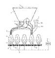
図1の照明装置は、複数の発光素子、一般には固体発光素子を含み、図示されている事例においては、基板2上に配設されるLED1を含む。LEDは、AlInGaPのLEDなどの多くの他のLEDより高い温度(電流)で動作され得るInGaNのLEDであり得る。 The lighting device of FIG. 1 includes a plurality of light emitting elements, generally solid state light emitting elements, and in the illustrated case, includes an LED 1 disposed on a
基板2には、LEDに電力及び任意の制御信号を供給する回路(図示せず)が設けられ、LEDが熱的に接続されるヒートシンク3も設けられる。ヒートシンクは、LEDによって生成される熱を放散するよう適合される。図示されている事例においては、ヒートシンク3は、基板2の背面に配設される相対的に薄いアルミニウム冷却フィンによって形成される。 The
一般的な用途においては、装置は、100乃至200個のLEDを有するが、この数は、この範囲を外れて変更してもよい。LEDは、ヒートシンク3による十分な熱放散を可能にするのに十分に大きな距離だけ互いから分離される。例として、LEDは、cmのオーダーの距離、例えば1cmだけ分離され得る。装置が、例えば、矩形(正方形)の11個×11個のアレイに配設される121個のLEDを有する場合には、これは、10cm×10cmのサイズをもたらし得る。 In typical applications, the device has between 100 and 200 LEDs, but this number may vary outside this range. The LEDs are separated from each other by a distance large enough to allow sufficient heat dissipation by the
装置は、各発光素子の上に配設される複数のコリメータ4を更に有する。各コリメータ4は、対応するLED1からの光を、一般に±30°未満の適切な角度範囲、及び一般に数mmの直径を持つ適切な領域にコリメートするよう構成される。例として、コリメータは、単一セルLED集光レンズであり得る。標準的なLEDに適しているこのような集光レンズは、例えばPolymer Optics社から容易に入手可能である。 The apparatus further includes a plurality of collimators 4 disposed on each light emitting element. Each collimator 4 is configured to collimate the light from the corresponding LED 1 into a suitable area with a suitable angular range, typically less than ± 30 °, and a diameter of typically a few millimeters. As an example, the collimator can be a single cell LED condenser lens. Such condenser lenses suitable for standard LEDs are readily available from, for example, Polymer Optics.
幾つかの、光ファイバ5のような可撓性の光導波路が、各コリメータレンズ4に接続され、各光ファイバは、レンズ4の焦点面に第1端部を持つ。適切な本数は、PMMAファイバの場合には、各LEDに対して10乃至100本であることができ、又は約50μmの直径を持つガラスファイバの場合には、各LEDに対して10000本前後であることができる。 Several flexible optical waveguides, such as
各ファイバ5の第2端部は、ビーム成形光学部品7の入口開口部6に配設され、故に、全LEDからの光が、十分な品質の光ビームを供給するために、ファイバによって、ビーム成形光学部品に案内される。ビーム成形光学部品7は、発光素子からの光を、(コリメータ4によって供給される任意のコリメーションに加えて)更にコリメートするよう構成され得る。例として、放射される光ビームは、10°乃至40°前後の半値全幅を持ち得る。ビーム成形光学部品7は、光ビームの拡大、及び(例えば「ウォッシュ」ビーム、「ハードエッジスポット」ビームなどへの)光ビームの成形も可能にし得る。 The second end of each
このような光学部品の例は、参照により本願明細書に盛り込まれるUS 6,200,002によって示されている。この事例においては、ビーム成形光学部品7は、入口開口部6を形成する第1端部と、より大きい出口開口部13を形成する他の端部とを備える管状反射器である。管状反射器の断面は、多角形、例えば、六角形、七角形又は八角形であり得る。各壁部の表面は、光軸から見て凸状であり得る。 An example of such an optical component is shown by US 6,200,002, which is incorporated herein by reference. In this case, the beam shaping optics 7 is a tubular reflector with a first end that forms the
エンターテイメント用途のための従来のビーム成形光学部品は、一般に、入口直径(入口開口部6の直径)と出口直径(出口開口部13の直径)との間で、約6乃至10の比を持つ。照明装置の全直径は、通常、約30cmまでに制限され、これは、光学部品の出口直径を制限する。従って、入口開口部は、3乃至5センチメートル程度の直径を持つだろう。本発明によれば、基板2の、発光素子1によって占められる領域は、ビーム成形光学部品7の入口開口部6より大きくてもよい。換言すれば、ファイバ5は、より大きな領域から光を集めて、入口開口部6のより小さい領域に集束させる。 Conventional beam shaping optics for entertainment applications typically have a ratio of about 6 to 10 between the entrance diameter (diameter of the entrance opening 6) and the exit diameter (diameter of the exit opening 13). The overall diameter of the illuminator is usually limited to about 30 cm, which limits the exit diameter of the optical component. Thus, the inlet opening will have a diameter on the order of 3-5 centimeters. According to the present invention, the area of the
或る実施例によれば、発光素子は、白色光の生成を可能にするために、異なる色の素子、例えば、赤色、緑色及び青色のLEDを有する。一般的なエンターテイメント照明用途においては、可変着色光の生成を可能にするために、4乃至8個の異なる色が必要とされる。色制御器8は、装置の色混合を制御するよう構成され得る。この事例においては、様々なLEDからのファイバが、好ましくは、色の異なるLEDからのファイバと混在させられ、故に、ファイバによって第1色混合が供給される。これは、図1において、2つのLED1a及び1bと、ファイバ5a及び5bとによって図示されており、これは、2つのLEDからの光が、既に、ビーム成形光学部品7の入口開口部6において、互いと混合されることを確実にする。混合は、ランダム化されてもよく、即ち、全LEDからの多数のファイバは、入口開口部においてランダムに混在させられてもよい。ビーム成形光学部品は、混在ファイバによって供給される色混合を更に改善するよう適合され得る。 According to one embodiment, the light emitting elements have different color elements, for example red, green and blue LEDs, in order to enable the generation of white light. In typical entertainment lighting applications, 4 to 8 different colors are required to allow the generation of variable colored light. The color controller 8 may be configured to control the color mixing of the device. In this case, the fibers from the various LEDs are preferably mixed with the fibers from the LEDs of different colors, and thus the first color mix is provided by the fibers. This is illustrated in FIG. 1 by two
或る実施例によれば、装置は、色制御器が、寿命にわたって、温度の関数として、異なる色のLEDの相対光束を較正値と等しいように保つことを可能にするために、色フィードバックを更に有する。フィードバックは、ここでは、各LEDからのファイバ10a、10bのうちの1つが接続されるカラーセンサ、例えば、フォトダイオード9を有する。その場合、フォトダイオード9の光束は、色制御器8にフィードバックされることができ、LEDを流れる電流を色ごとに制御するのに用いられることができる。 According to one embodiment, the device provides color feedback to allow the color controller to keep the relative luminous flux of different color LEDs equal to the calibration value as a function of temperature over the lifetime. Also have. The feedback here has a color sensor, for example a photodiode 9, to which one of the
これは、少なくとも2つの異なる方法で実施されることができる。図1に図示されている第1手法によれば、各LEDからの1つのファイバ10a、10bが、時間的に順次に各色の出力を測定するよう構成される単一の光センサ9に接続される。この実施例には、光センサの経年劣化に影響されないという利点を持つ。フォトダイオードの場合には、2つの異なるセンサには、異なる経年劣化特性があり得る。全ての色に対して同じセンサが用いられるので、波長依存経年劣化がなければ、相対強度は変わらないだろう。 This can be implemented in at least two different ways. According to the first approach illustrated in FIG. 1, one
図2に図示されている第2手法によれば、各色に対して1つのセンサ9a、9bが配設され、連続的な光束監視を可能にする。同じ色のLEDに接続される全てのファイバ11a、11bが、同じセンサ9a、9bに接続される。この実施例は、順次的なタイミング制御を必要としないので、より少ない制御回路しか必要としない。 According to the second method shown in FIG. 2, one
当業者には、本発明が、決して、上記の好ましい実施例に限定されないことは分かるであろう。逆に、添付の請求項の範囲内で多くの修正及び変更が可能である。例えば、1つ又は2つのダイクロイックミラーを介して1つのファイバに2色又は3色を挿入することによって、入口開口部6における光束/mm2を更に増大させることが可能である。Those skilled in the art will appreciate that the present invention by no means is limited to the preferred embodiments described above. On the contrary, many modifications and variations are possible within the scope of the appended claims. For example, it is possible to further increase the luminous flux / mm2 at the
Claims (13)
Translated fromJapanese入口開口部を持つビーム成形光学部品と、
前記発光素子の光束を制御するための制御器と、
前記制御器に接続される光センサとを有する照明装置であり、
各発光素子が、各々が、前記発光素子からのコリメート光を前記ビーム成形光学部品に案内するために、前記発光素子に光学的に接続される第1端部と、前記入口開口部に光学的に接続される第2端部とを持つ光ファイバのセットに光学的に接続される照明装置であって、
光ファイバの各セットが、前記発光素子に光学的に接続される第1端部と、前記光センサに光学的に接続される第2端部とを持つ光ファイバを少なくとも1つ更に有し、
前記発光素子が、前記入口開口部より大きな領域にわたって分布している照明装置。A plurality of light emitting elements;
A beam shaping optic with an entrance opening;
A controller for controlling the luminous flux of the light emitting element;
A lighting device havinga light sensor connected to the controller ,
Each light emitting element is optically connected to a first end optically connected to the light emitting element and to the entrance opening for guiding collimated light from the light emitting element to the beam shaping optical component. A lighting device optically connected to a set of optical fibers having a second end connected to
Each set of optical fibers further comprises at least one optical fiber having a first end optically connected to the light emitting element and a second end optically connected to the photosensor;
The lighting device in which the light emitting elements are distributed over a region larger than the entrance opening.
Applications Claiming Priority (3)
| Application Number | Priority Date | Filing Date | Title |
|---|---|---|---|
| EP09174986AEP2320125A1 (en) | 2009-11-04 | 2009-11-04 | Lighting device |
| EP09174986.1 | 2009-11-04 | ||
| PCT/IB2010/054892WO2011055281A1 (en) | 2009-11-04 | 2010-10-28 | Lighting device |
Publications (2)
| Publication Number | Publication Date |
|---|---|
| JP2013510387A JP2013510387A (en) | 2013-03-21 |
| JP5711246B2true JP5711246B2 (en) | 2015-04-30 |
Family
ID=41727841
Family Applications (1)
| Application Number | Title | Priority Date | Filing Date |
|---|---|---|---|
| JP2012535999AExpired - Fee RelatedJP5711246B2 (en) | 2009-11-04 | 2010-10-28 | Lighting device |
Country Status (5)
| Country | Link |
|---|---|
| US (1) | US9229145B2 (en) |
| EP (2) | EP2320125A1 (en) |
| JP (1) | JP5711246B2 (en) |
| CN (1) | CN102597606B (en) |
| WO (1) | WO2011055281A1 (en) |
Families Citing this family (7)
| Publication number | Priority date | Publication date | Assignee | Title |
|---|---|---|---|---|
| JP2014516199A (en)* | 2011-06-10 | 2014-07-07 | コーニンクレッカ フィリップス エヌ ヴェ | Configuration for optical balancing |
| CN103649818A (en)* | 2011-07-15 | 2014-03-19 | 皇家飞利浦有限公司 | Luminaire emitting light of different colours |
| DE102016114694A1 (en)* | 2016-08-09 | 2018-02-15 | Arnold & Richter Cine Technik Gmbh & Co. Betriebs Kg | Headlight and light source arrangement for a headlight |
| WO2019143973A1 (en)* | 2018-01-22 | 2019-07-25 | Quarkstar Llc | Lighting system and luminaire with optical fiber coupled light sources |
| TWI661573B (en)* | 2018-06-01 | 2019-06-01 | 宇瞻科技股份有限公司 | Multispectral light source device |
| US10652974B2 (en)* | 2018-07-20 | 2020-05-12 | The Boeing Company | Fiber optic twinkling star patterns by means of light engine and specialized optics |
| EP3865764B1 (en)* | 2018-07-30 | 2025-09-03 | Thorn Lighting Ltd. | Luminaire |
Family Cites Families (13)
| Publication number | Priority date | Publication date | Assignee | Title |
|---|---|---|---|---|
| SE436223B (en) | 1980-12-16 | 1984-11-19 | Sieverts Kabelverk Ab | FIBEROPTIC LAMP |
| US6164789A (en) | 1996-07-12 | 2000-12-26 | Honeywell International Inc. | Illumination sources and systems |
| WO2000035402A1 (en)* | 1998-12-17 | 2000-06-22 | Getinge/Castle, Inc. | Illumination system adapted for surgical lighting |
| US6200002B1 (en) | 1999-03-26 | 2001-03-13 | Philips Electronics North America Corp. | Luminaire having a reflector for mixing light from a multi-color array of leds |
| IES20000322A2 (en)* | 2000-04-28 | 2001-11-14 | Viveen Ltd | Apparatus for testing a light source |
| US6921920B2 (en)* | 2001-08-31 | 2005-07-26 | Smith & Nephew, Inc. | Solid-state light source |
| JP2004078145A (en)* | 2001-11-09 | 2004-03-11 | Ccs Inc | Light supply arrangement |
| US20030112639A1 (en)* | 2001-12-18 | 2003-06-19 | Michael Stack | LED based optical fiber illuminator and controller |
| US6655825B2 (en)* | 2001-12-28 | 2003-12-02 | Koninklijke Philips Electronics N.V. | White light source for LCD backlight |
| US7023543B2 (en)* | 2002-08-01 | 2006-04-04 | Cunningham David W | Method for controlling the luminous flux spectrum of a lighting fixture |
| JP4167131B2 (en)* | 2003-06-09 | 2008-10-15 | 株式会社モリテックス | Lighting device |
| JP2006004862A (en) | 2004-06-21 | 2006-01-05 | Toshiba Lighting & Technology Corp | LED spotlight |
| CN101292574B (en)* | 2005-08-17 | 2012-12-26 | 皇家飞利浦电子股份有限公司 | Digitally controlled luminaire system |
- 2009
- 2009-11-04EPEP09174986Apatent/EP2320125A1/ennot_activeCeased
- 2010
- 2010-10-28EPEP10782398Apatent/EP2496878A1/ennot_activeWithdrawn
- 2010-10-28CNCN201080050047.9Apatent/CN102597606B/ennot_activeExpired - Fee Related
- 2010-10-28USUS13/505,105patent/US9229145B2/ennot_activeExpired - Fee Related
- 2010-10-28JPJP2012535999Apatent/JP5711246B2/ennot_activeExpired - Fee Related
- 2010-10-28WOPCT/IB2010/054892patent/WO2011055281A1/enactiveApplication Filing
Also Published As
| Publication number | Publication date |
|---|---|
| US9229145B2 (en) | 2016-01-05 |
| EP2496878A1 (en) | 2012-09-12 |
| CN102597606B (en) | 2016-06-22 |
| US20120212971A1 (en) | 2012-08-23 |
| WO2011055281A1 (en) | 2011-05-12 |
| JP2013510387A (en) | 2013-03-21 |
| CN102597606A (en) | 2012-07-18 |
| EP2320125A1 (en) | 2011-05-11 |
Similar Documents
| Publication | Publication Date | Title |
|---|---|---|
| US9169997B2 (en) | Arrangement for spot illumination | |
| JP5711246B2 (en) | Lighting device | |
| US8408772B2 (en) | LED illumination device | |
| US20120217519A1 (en) | Method and structure for encapsulating solid-state light emitting chip and light sources using the encapsulation structure | |
| US8888294B2 (en) | Cooling module for multiple light source projecting device | |
| CN107806572B (en) | Luminaire comprising a light source, lenslets and a retroreflector | |
| KR20150143656A (en) | Light-emitting device and projection system | |
| US20130027442A1 (en) | Projecting Device With Multiple Mutual Boosting Light Sources | |
| JP6009558B2 (en) | Lighting equipment that emits light of different colors | |
| EP2810121B1 (en) | An improved light collimation system | |
| CN103899990B (en) | Backlight module and display device | |
| CN102971581B (en) | Light source unit with phosphor element | |
| KR102085955B1 (en) | A lighting device using a led | |
| KR102500319B1 (en) | High brightness light source device including pluratlify of lazer light sources arranged around optical axis | |
| CN204966964U (en) | White light laser module, laser display system and laser projection system | |
| JP2013211252A (en) | Solid lighting device | |
| JP2013222552A (en) | Solid state lighting device |
Legal Events
| Date | Code | Title | Description |
|---|---|---|---|
| A621 | Written request for application examination | Free format text:JAPANESE INTERMEDIATE CODE: A621 Effective date:20131015 | |
| A131 | Notification of reasons for refusal | Free format text:JAPANESE INTERMEDIATE CODE: A131 Effective date:20140715 | |
| A521 | Request for written amendment filed | Free format text:JAPANESE INTERMEDIATE CODE: A523 Effective date:20141015 | |
| TRDD | Decision of grant or rejection written | ||
| A01 | Written decision to grant a patent or to grant a registration (utility model) | Free format text:JAPANESE INTERMEDIATE CODE: A01 Effective date:20150203 | |
| A61 | First payment of annual fees (during grant procedure) | Free format text:JAPANESE INTERMEDIATE CODE: A61 Effective date:20150305 | |
| R150 | Certificate of patent or registration of utility model | Ref document number:5711246 Country of ref document:JP Free format text:JAPANESE INTERMEDIATE CODE: R150 | |
| S111 | Request for change of ownership or part of ownership | Free format text:JAPANESE INTERMEDIATE CODE: R313113 | |
| R350 | Written notification of registration of transfer | Free format text:JAPANESE INTERMEDIATE CODE: R350 | |
| LAPS | Cancellation because of no payment of annual fees |