JP5709649B2 - Communication system, automatic meter reading system and monitoring server - Google Patents
Communication system, automatic meter reading system and monitoring serverDownload PDFInfo
- Publication number
- JP5709649B2 JP5709649B2JP2011124377AJP2011124377AJP5709649B2JP 5709649 B2JP5709649 B2JP 5709649B2JP 2011124377 AJP2011124377 AJP 2011124377AJP 2011124377 AJP2011124377 AJP 2011124377AJP 5709649 B2JP5709649 B2JP 5709649B2
- Authority
- JP
- Japan
- Prior art keywords
- gateway
- communication unit
- communication
- failure
- identification information
- Prior art date
- Legal status (The legal status is an assumption and is not a legal conclusion. Google has not performed a legal analysis and makes no representation as to the accuracy of the status listed.)
- Active
Links
Images


Landscapes
- Arrangements For Transmission Of Measured Signals (AREA)
- Selective Calling Equipment (AREA)
- Mobile Radio Communication Systems (AREA)
- Telephonic Communication Services (AREA)
Description
Translated fromJapanese本発明は、電気や水道、ガスなどの使用量を自動で検針するシステムの構築に利用される通信システム、および自動検針システムに関するものである。 The present invention relates to a communication system and an automatic meter reading system that are used to construct a system that automatically measures the amount of electricity, water, gas, etc. used.
近年、複数の通信ユニットが相互に無線通信し、マルチホップすることで広域ネットワークを形成するアドホック通信を、電気、水道、ガスといった各種自動検針のネットワークインフラとして適用する形態が検討されている。このアドホック通信を用いることで、設備コストを抑えつつ、広範囲エリアをカバーする自動検針システムが実現できる(非特許文献1参照)。 In recent years, a form in which ad hoc communication in which a plurality of communication units communicate with each other wirelessly and form a wide area network by multi-hopping is applied as a network infrastructure for various automatic meter readings such as electricity, water, and gas has been studied. By using this ad hoc communication, it is possible to realize an automatic meter reading system that covers a wide area while suppressing equipment costs (see Non-Patent Document 1).
アドホック通信での経路確立は無線通信端末(通信ユニット)間で経路情報を交換することで、ネットワークを構築する。この経路情報の交換手段、経路確立(ルーティングプロトコル)の方式はIETF(Internet Engineering Task Force)で複数検討、標準化されている(非特許文献2参照)。 In the establishment of a route in ad hoc communication, a network is constructed by exchanging route information between wireless communication terminals (communication units). A plurality of route information exchanging means and route establishment (routing protocol) methods have been studied and standardized by IETF (Internet Engineering Task Force) (see Non-Patent Document 2).
自動検針システムでは、アドホック通信ネットワークインフラ経由で検針データの収集やネットワークの監視・制御を担う業務アプリケーションを動作させることになるが、同一無線メディアのアドホック通信によって各通信ユニットからデータセンタ内の業務サーバ(検針データを収集するサーバ)までのネットワークインフラを提供することは、マルチホップ数及び収集トラヒック量の観点から現実的ではない。そのため、アドホック通信ネットワークと既存IPネットワークを中継する分散配置されたゲートウェイが通信メディア変換・プロトコル変換を行うことによって、業務サーバと各通信ユニットとの通信を可能とするシステムモデルを想定している。 In the automatic meter reading system, business applications responsible for collecting meter reading data and monitoring / controlling the network are operated via the ad hoc communication network infrastructure. From the communication unit to the business server in the data center by ad hoc communication using the same wireless media. Providing a network infrastructure up to (a server that collects meter reading data) is not realistic from the viewpoint of the number of multihops and the amount of collected traffic. Therefore, a system model is assumed that enables communication between the business server and each communication unit by performing communication media conversion / protocol conversion by gateways arranged in a distributed manner that relay the ad hoc communication network and the existing IP network.
自動検針システムにおいて、ゲートウェイが故障した場合には、そのゲートウェイ経由で通信経路が確立されている通信ユニット群を業務サーバが制御できなくなる。すなわち、検針データの収集等が不可能となってしまう。自動検針システムの全面展開において、ゲートウェイは通信ユニットの周囲に複数設置されるため、仮に1台のゲートウェイが故障したとしても周辺ゲートウェイによる面的カバーが可能であるが、故障したゲートウェイと周辺の他ゲートウェイが異なる無線チャネルを使用するように構築されることもありうる。この場合、故障したゲートウェイ配下の各通信ユニットが自律的に現接続ゲートウェイの故障を検出し、周辺の他ゲートウェイとの新たな通信経路を確立するまで、業務サーバが当該通信ユニット群を制御することができない。通常、各通信ユニットが自律的に故障を検出して新たな通信経路を確立するまでには非常に長い時間を要する。 In the automatic meter reading system, when a gateway fails, the business server cannot control a communication unit group in which a communication path is established via the gateway. That is, meter reading data cannot be collected. In the full deployment of the automatic meter reading system, a plurality of gateways are installed around the communication unit, so even if one gateway fails, it is possible to cover the area with the surrounding gateways. It is possible that the gateway is constructed to use different radio channels. In this case, the business server controls the communication unit group until each communication unit under the failed gateway autonomously detects a failure of the current connection gateway and establishes a new communication path with other surrounding gateways. I can't. Normally, it takes a very long time for each communication unit to autonomously detect a failure and establish a new communication path.
本発明は、上記に鑑みてなされたものであって、自動検針のためのEnd-to-End通信において、アドホック通信ネットワークのゲートウェイが故障した場合に、故障したゲートウェイ配下の各通信ユニットと検針データを収集する業務サーバとの間の通信を短時間で復旧させることが可能な通信システムおよび自動検針システムを得ることを目的とする。 The present invention has been made in view of the above, and in end-to-end communication for automatic meter reading, when a gateway of an ad hoc communication network fails, each communication unit and meter reading data under the failed gateway An object of the present invention is to obtain a communication system and an automatic meter-reading system that can restore communication with a business server that collects information in a short time.
上述した課題を解決し、目的を達成するために、本発明にかかる通信システムは、ゲートウェイ、および当該ゲートウェイに収容されている通信ユニットにより形成されたアドホック通信ネットワークを複数備えるとともに、各アドホック通信ネットワークのゲートウェイを監視する監視サーバを備え、前記監視サーバは、前記通信ユニットそれぞれについて、直接通信が可能な通信ユニットである隣接通信ユニットとその接続先ゲートウェイの情報を収集・管理し、ゲートウェイの故障を検出した場合、当該検出したゲートウェイに接続中の通信ユニットと直接通信が可能な位置に存在し、かつ当該検出したゲートウェイとは異なるゲートウェイに接続中の通信ユニットである境界通信ユニットを介して、故障したゲートウェイの識別情報を含む信号を、当該検出したゲートウェイに接続中の通信ユニットへ送信する、ことを特徴とする。 In order to solve the above-described problems and achieve the object, a communication system according to the present invention includes a plurality of ad hoc communication networks formed by a gateway and a communication unit accommodated in the gateway, and each ad hoc communication network. The monitoring server collects and manages information on adjacent communication units that are directly communicable communication units and their connection destination gateways for each of the communication units, and detects gateway failures. If detected, a failure occurs via a boundary communication unit that exists in a position where direct communication with the communication unit connected to the detected gateway is possible and is connected to a gateway different from the detected gateway. Gateway identification information A signal containing, for transmitting to the communication unit in connection to the detected Gateway, characterized in that.
この発明によれば、故障が発生したゲートウェイ配下の通信ユニット群に対してゲートウェイの故障発生を通知し、正常動作中の他のゲートウェイに速やかに再参入させることができ、故障したゲートウェイ配下にあった通信ユニットと業務サーバとの間の通信を短時間で復旧させることができる、という効果を奏する。 According to the present invention, the occurrence of a gateway failure can be notified to a communication unit group under the gateway in which the failure has occurred, and another gateway in normal operation can be quickly re-entered. The communication unit and the business server can be restored in a short time.
以下に、本発明にかかる通信システムおよび自動検針システムの実施の形態を図面に基づいて詳細に説明する。なお、この実施の形態によりこの発明が限定されるものではない。 Embodiments of a communication system and an automatic meter reading system according to the present invention will be described below in detail with reference to the drawings. Note that the present invention is not limited to the embodiments.
実施の形態1.
図1は、本発明にかかる通信システムの実施の形態1の構成例を示す図である。図1に示したように、本実施の形態の通信システムは、上位サーバ1と、ゲートウェイ2Aおよび2Bと、通信ユニット3A1〜3A4,3B1〜3B5と、を含み、上位サーバ1とゲートウェイ2A,2Bは、インターネット、社内網、アクセス網などの既存ネットワークを介して接続されている。
FIG. 1 is a diagram showing a configuration example of a first embodiment of a communication system according to the present invention. As shown in FIG. 1, the communication system of this embodiment includes a
通信ユニット3A1〜3A4および通信ユニット3B1〜3B5は、それぞれ1つのアドホック通信ネットワーク(以下、アドホックネットワークと称する)を形成している。具体的には、通信ユニット3A1〜3A4はゲートウェイ2Aに収容され、このゲートウェイ2Aを介して上位サーバと通信を行う。通信ユニット3B1〜3B5はゲートウェイ2Bに収容され、このゲートウェイ2Bを介して上位サーバと通信を行う。また、本実施の形態では、ゲートウェイ2Aおよびその配下の各通信ユニットが無線チャネルxを使用して通信を行い、ゲートウェイ2Bおよびその配下の各通信ユニットが無線チャネルy(≠x)を使用して通信を行うものとする。Each of the
ゲートウェイ2Aと2Bは同じ機能を有しており、通信ユニット3A1〜3A4,3B1〜3B5は同じ機能を有している。これ以降の説明においては、ゲートウェイ2Aと2Bに共通の事項を説明する場合など、2つのゲートウェイを区別する必要がない場合、これらを総称して「ゲートウェイ2」と記載する。通信ユニット3A1〜3A4,3B1〜3B5についても同様に、各通信ユニットを区別する必要がない場合には「通信ユニット3」と記載する。The
なお、通信システムの構成は図1に示したものに限定されない。ゲートウェイ2は3台以上であってもよく、各ゲートウェイ配下の通信ユニット3の台数をさらに多くしてもよい。もちろん、少ない台数としてもよい。 The configuration of the communication system is not limited to that shown in FIG. Three or
上記構成の通信システムにおいて、上位サーバ1は、ゲートウェイ2Aまたは2Bを介して各通信ユニット3を制御し、検針データ(需要家の電気、ガスまたは水道の使用量)を収集する。また、アドホックネットワークの状態監視を行ってゲートウェイ2の故障を検出する機能を有する。アドホックネットワークの状態監視においては、ゲートウェイ2の故障検出の他、各アドホックネットワークに参入している通信ユニット3の物理的な位置関係(直接通信が可能な隣接関係にある通信ユニットの組み合わせ)の情報と、各通信ユニット3が収容されているゲートウェイ(接続中のゲートウェイ)の情報と、各通信ユニット3がアドホックネットワーク内での通信で使用する無線チャネルの情報とを各通信ユニット3から収集して記憶する動作を実施する。情報は、例えば、一定周期で各通信ユニットから収集する。また、通信ユニット3がアドホックネットワークに参入した際に、接続したゲートウェイの識別情報と、隣接関係にある通信ユニットの識別情報と、使用無線チャネルの識別情報とを通知させることにより収集してもよい。 In the communication system configured as described above, the
なお、この上位サーバ1を、通信ユニット3から検針データを収集するサーバ(例えば業務サーバ)と、各ゲートウェイ2,各通信ユニット3を監視してアドホックネットワークの異常検出(ゲートウェイ2の故障検出など)を行うサーバ(例えば監視サーバ)の2つに分けてもよい。 The
各通信ユニット3は、需要家に設置され、上位サーバ1からの指示に従い、電気、ガス、水道等の使用量を示す検針データを上位サーバ1へ送信する。詳細については後述するが、検針データの取得機能は通信ユニット3が備えていてもよいし、当該機能を備えた他の装置を接続できるように通信ユニット3を構成し、通信ユニット3は接続された装置を利用して検針データを取得するようにしてもよい。 Each
図2は、通信ユニット3の機能ブロック構成の一例を示す図であり、通信ユニット3は、無線インタフェイス(I/F)31、送受信部32、経路制御部33、ゲートウェイ/無線チャネル切替処理部34、隣接機器情報記憶部35、ユニット制御部36および他ユニットインタフェイス(I/F)37を備える。 FIG. 2 is a diagram illustrating an example of a functional block configuration of the
通信ユニット3において、無線I/F31は、他装置との通信データのフレーム化(もしくはその逆)を行う。なお、無線媒体は特定小電力無線、無線LAN、PHS等を想定する。 In the
送受信部32は、無線I/F31を介して他の装置(通信ユニット、ゲートウェイ、上位サーバ、等)との間で送受信される通信データのフォーマット解析やフレーム生成を行い、図示を省略した上位制御部とのデータ中継を行う。また、フレーム化されたデータを精査し、フレームエラー検査を行う(チェックサム、巡回冗長検査等の付加データを使用して、フレーム単位での再送制御などを行う)。フレームを正常に受信した場合には、受信フレームを経路制御部33に出力する。 The transmission /
経路制御部33は、アドホックネットワークを構築するために、隣接する通信ユニットと通信を行い、隣接している他の通信ユニット(以下、隣接通信ユニットと称する)の装置識別子、使用帯域(チャネル)、ゲートウェイまでのホップ数、受信信号強度(隣接通信ユニットからの受信信号の強度)など経路確立に関する情報の交換を行う。加えて、送受信部32から受信フレームが入力された場合、フレームのヘッダを解析して自装置宛か否かを判断し、自装置宛の場合、ユニット制御部36に中継する。自装置宛ではなく他の装置宛の場合には、保持している経路管理表を確認して次の中継装置(通信ユニットまたはゲートウェイ)を特定し、送受信部32および無線I/F31経由で転送する。 The path control
ゲートウェイ/無線チャネル切替処理部34は、本実施の形態の通信システム実現のためのキーとなる制御部である。詳細動作については後述するが、自装置を収容しているゲートウェイとは異なるゲートウェイに収容されている隣接通信ユニットと直接通信を行えるように、必要に応じて無線チャネルを切り替える。また、接続中のゲートウェイが故障したことを他の通信ユニットから通知された場合には、接続するゲートウェイを切り替えるための動作(接続先ゲートウェイの再選択)を実行する。 The gateway / wireless channel switching processing unit 34 is a control unit that is a key for realizing the communication system of the present embodiment. Although the detailed operation will be described later, the radio channel is switched as necessary so that direct communication can be performed with an adjacent communication unit accommodated in a gateway different from the gateway accommodating the device itself. In addition, when another communication unit notifies that the connected gateway has failed, an operation for switching the gateway to be connected (reselection of the connection destination gateway) is executed.
隣接機器情報記憶部35は、隣接通信ユニットの情報、具体的には、各隣接通信ユニットの識別情報、各隣接通信ユニットが接続中のゲートウェイの識別情報、各隣接通信ユニットが通信で使用している無線チャネルの情報(隣接通信ユニットとの通信で使用する無線チャネルの情報)を記憶する。接続中ゲートウェイの識別情報は、例えば、アドホックネットワークに参入する際に各隣接通信ユニットから取得する。すなわち、参入動作における隣接通信ユニット検索において、接続中のゲートウェイを各隣接通信ユニットに問い合わせ、この情報を取得する。 The adjacent device
ユニット制御部36は、上位サーバ1から自通信ユニット宛に送信された制御電文(制御メッセージ)に従い、自通信ユニット内の各部の制御を行う。また、応答電文生成を行う。また、必要に応じて他ユニットI/F37経由で接続している各種ユニット38の制御を行う。 The
他ユニットI/F37は、外部の各種ユニット38を接続するための物理的なインタフェイスであり、通信媒体を指す(有線・無線を問わない)。複数の外部ユニットを同時に接続できる構成としてもよい。 The other unit I /
各種ユニット38は、ガス、水道、電気等のメータ検針値を記録する計量ユニットやサービス提供開始・停止を制御する開閉ユニットといった、アドホック通信ネットワークシステムを使用したセンサ情報(検針データ)取得するための制御対象装置である。 The
なお、図2においては、ガス、水道、電気等の検針データを取得する装置を接続するためのインタフェイス(他ユニットI/F37)を備え、外部の制御対象装置を利用して検針データを取得する通信ユニットについて示したが、通信ユニットが検針データを直接取得できるような構成としてもよい。 In FIG. 2, an interface (other unit I / F 37) for connecting a device for acquiring meter reading data such as gas, water and electricity is provided, and meter reading data is acquired using an external control target device. Although the communication unit is shown, the communication unit may directly acquire meter reading data.
以下、図1に示した通信システムの全体動作について説明する。本実施の形態の通信システムの特徴は、ゲートウェイ2が故障した場合の動作、より詳細には、ゲートウェイ2が故障し、その配下の通信ユニット3と上位サーバ1が通信できない状態となった場合に、短時間で復旧させる動作にある。そのため、ゲートウェイ2が故障した場合の動作を中心に説明を行う。ここでは、一例として、ゲートウェイ2Aが故障し、その配下の通信ユニット3A1〜3A4を上位サーバ1が制御できなくなった場合の動作を説明する。Hereinafter, the overall operation of the communication system shown in FIG. 1 will be described. The feature of the communication system of the present embodiment is the operation when the
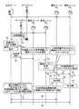
図3は、図1に示した通信システムにおいてゲートウェイ2Aが故障した場合の動作例を示す図である。図4は、図3に示した動作例に対応する制御シーケンス例を示す図である。なお、図4においては、簡単化のために、通信ユニット3A1,3A2,3B1,3B2に関する制御のみを示している。他の通信ユニット(3A3,3A4,3B3,3B4,3B5)に対する制御も同様である。FIG. 3 is a diagram showing an operation example when the
図3の(1)〜(6)で示したように、本実施の形態の通信システムにおいて、上位サーバ1は各ゲートウェイの状態を監視し、例えばゲートウェイ2Aの故障を検出した場合には、故障したゲートウェイ2Aに収容されている通信ユニット3A1〜3A4との通信を維持する(復旧させる)ために、これらの通信ユニット3A1〜3A4の中の少なくとも1つに隣接し、かつゲートウェイ2Aとは異なるゲートウェイ(ここではゲートウェイ2Bとなる)に収容されている通信ユニットを境界通信ユニットとして選択する。図3に示した例では通信ユニット3B2を境界通信ユニットとして選択する。そして、選択した境界通信ユニット(通信ユニット3B2)に対して、ゲートウェイ2Aに収容されている通信ユニット3A1〜3A4が使用中の無線チャネル上にゲートウェイ故障通知パケット(ゲートウェイ2Aが故障したことを示す情報を含んでいる)をブロードキャスト送信するよう指示を出す。As shown in (1) to (6) of FIG. 3, in the communication system according to the present embodiment, the
ゲートウェイ2Aの故障を示すゲートウェイ故障通知パケットのブロードキャスト送信指示を受けた通信ユニット3B2は、故障したゲートウェイ2Aに収容されている通信ユニット3A1〜3A4が使用中の無線チャネル(チャネルy)上に、ゲートウェイ故障通知パケットをブロードキャストする。通信ユニット3A1〜3A4は、ブロードキャストされたゲートウェイ故障通知パケットを受信すると、それをブロードキャスト転送する。The
ここで、アドホックネットワークに参入済みの通信ユニット3は、既に説明したように、各隣接通信ユニットの識別情報、各隣接通信ユニットが接続中のゲートウェイ(収容されているゲートウェイ)の識別情報、各隣接通信ユニットが通信で使用している無線チャネル(各隣接通信ユニットとの通信で使用する無線チャネル)の情報を把握している。よって、境界通信ユニットとして選択された通信ユニット3B2は、ゲートウェイ2Aが故障したことを示すゲートウェイ故障通知パケットを受信した場合、このゲートウェイ2Aに収容されている通信ユニット3A1〜3A4が使用中の無線チャネルを特定可能である。Here, as already explained, the
ゲートウェイ故障通知パケットを受信した通信ユニット3A1〜3A4は、ゲートウェイ2Aが故障したことを示すゲートウェイ故障通知パケットを受信すると、接続先のゲートウェイを切り替える必要があると認識し、ゲートウェイ切替(再選択)を実行する。Upon receiving the gateway failure notification packet indicating that the
以上の動作に対応する制御シーケンス手順は以下の通りとなる(図4参照)。 The control sequence procedure corresponding to the above operation is as follows (see FIG. 4).
上位サーバ1は、監視下のゲートウェイ(以降、GWと記述)に対して周期的な死活監視(IPネットワークで利用されるpingによる疎通確認、ネットワーク監視プロトコルによる機器監視、上位アプリケーションによるサービス要求など)を所定のタイミングで実施し、GW2Aの故障を検出する(ステップS1)。 The
上位サーバ1は、制御対象の通信ユニットごとに、図5に示したような、接続GW(接続中のGW)および隣接GWの情報(詳細は後述する)を管理しており、GWの故障を検出した場合には、この情報に従って、故障GWに接続中の通信ユニットに隣接し、かつ他のGW(故障GW以外のGW)に接続中の通信ユニット(上述した境界通信ユニットに相当)を選択する(ステップS2)。本実施の形態ではGW2Aが故障した場合を想定しているので、通信ユニット3B2を選択する。The
ここで、図5に示した情報について説明する。図5において、左から2列目の「ユニットID」は通信ユニットの識別情報である。また、「接続GW」情報には、「ユニットID」が示す通信ユニットが接続中のGWの識別情報である「接続GWID」,「ユニットID」が示す通信ユニットが使用している無線チャネルの識別情報である「使用無線CH」が含まれ、「隣接GW」情報(隣接GW#1,#2,…)には、それぞれ、左から2列目の「ユニットID」が示す通信ユニットの隣接通信ユニットの識別情報である「隣接ユニットID」,この隣接通信ユニットが接続中のGWの識別情報である「隣接GWID」,隣接通信ユニットが使用している無線チャネルの識別情報である「隣接無線CH」が含まれる。左から2列目の「ユニットID」が示す通信ユニットに対して、同一行の「隣接ユニットID」が示す通信ユニットが境界通信ユニットとなる。なお、「隣接ユニットID」が示す通信ユニット側から見た場合も同様に、同一行の左から2列目の「ユニットID」が示す通信ユニットが境界通信ユニットとなる(図5の「No 1」,「No 4」行参照)。 Here, the information shown in FIG. 5 will be described. In FIG. 5, “unit ID” in the second column from the left is identification information of the communication unit. The “connection GW” information includes “connection GWID”, which is identification information of the GW that is connected to the communication unit indicated by “unit ID”, and identification of the wireless channel used by the communication unit indicated by “unit ID”. “Used radio CH” as information is included, and “adjacent GW” information (
このように、境界通信ユニットは、自ユニットが参加しているアドホックネットワークとは異なるアドホックネットワークに参入している他の通信ユニットと隣接している(直接通信することが可能な)通信ユニットとなる。 In this way, the boundary communication unit is a communication unit that is adjacent to (can be directly communicated with) another communication unit that has entered an ad hoc network different from the ad hoc network in which the unit is participating. .
図5に示した情報は、例えば、接続中のゲートウェイの識別情報(接続GWID)と、隣接関係にある通信ユニットの識別情報(隣接ユニットID)と、使用する無線チャネルの識別情報(使用無線CH)とを各通信ユニットから一定周期で収集し、収集した情報に基づいて作成・更新する。この他、通信ユニット3がアドホックネットワークに参入した際に、これらの情報を通知させて収集してもよい。このとき、隣接GWID,隣接無線CHも併せて収集してもよいが、この2つの情報は、境界通信ユニットとなる通信ユニット(「隣接ユニットID」に対応する通信ユニット)から通知されてくるものであるため、それを利用可能である。隣接GWID,隣接無線CHを通知させないようにすることで、上位サーバ1が収集するデータ量を抑えることができ、その結果、ネットワーク内のトラヒックの増大を防止するとともに、装置(通信ユニット,GW)の処理負荷を軽減できる。なお、隣接GWは通信ユニット毎に1個に限らず、記憶容量が許す範囲で複数の「隣接GW」の情報を蓄積しても構わない(図5の「No 1」行参照)。 The information shown in FIG. 5 includes, for example, identification information of a gateway being connected (connection GWID), identification information of a communication unit in an adjacent relationship (adjacent unit ID), and identification information of a wireless channel to be used (used wireless CH ) Are collected from each communication unit at regular intervals, and created and updated based on the collected information. In addition, when the
また、図5に示したデータ構成においては、管理するデータ量を少なくするとともに、GW故障時における境界通信ユニットの選択処理を短時間で完了できるようにするため、1つの通信ユニット(「ユニットID」が示す通信ユニット)に対して、この通信ユニットに隣接している通信ユニット(隣接通信ユニット)のうち、この通信ユニットが接続中のGWとは異なるGWに接続中の隣接通信ユニット(すなわち、境界通信ユニット)に関する情報のみを登録するようにしている。メモリ容量や境界通信ユニットの選択処理時間が問題とならない場合には、1つの通信ユニットに対して、全ての隣接通信ユニット(同じGWに接続中の隣接通信ユニットを含む)に関する情報を登録するようにしても構わない。 Further, in the data configuration shown in FIG. 5, in order to reduce the amount of data to be managed and to complete the boundary communication unit selection process at the time of a GW failure in a short time, one communication unit (“unit ID” ) Among the communication units (adjacent communication units) adjacent to this communication unit (i.e., adjacent communication units connected to a GW different from the GW to which the communication unit is connected (i.e. Only information related to the boundary communication unit) is registered. If the memory capacity and the selection processing time of the boundary communication unit are not a problem, information about all adjacent communication units (including adjacent communication units connected to the same GW) is registered for one communication unit. It doesn't matter.
上位サーバ1は、次に、上記ステップS2で選択した、故障GW2Aのアドホックネットワークの境界通信ユニット3B2に対して、GW2B経由でゲートウェイ故障通知パケットをユニキャストフレームで送信する(ステップS3)。Next, the
ゲートウェイ故障通知パケットを受信した通信ユニット3B2は、故障通知パケット内の情報を確認して故障GWを特定し、故障GW(ここではGW2Aとなる)のアドホックネットワーク内で使用されているものと同一の無線チャネル(チャネルx)上に対して、ゲートウェイ故障通知パケットをブロードキャスト送信する(ステップS4,S5)。なお、ステップS4は、通信ユニット3B2の接続中GWのアドホックネットワーク内で使用されている無線チャネルと故障GWのアドホックネットワーク内で使用されている無線チャネルが一致している場合には省略される。The
ゲートウェイ故障通知パケットを受信したGW2A配下の通信ユニット3A1〜3A4は、ゲートウェイ故障通知パケットを下流の通信ユニットに対してブロードキャスト転送する(ステップS6)。また、一定時間経過後に、隣接GW探索を実施して接続先のGWを切り替える(ステップS7)。なお、複数のゲートウェイ故障通知パケットを受信した場合、すなわち、接続可能なGWが複数存在する場合には、無線品質やホップ数(受信した各ゲートウェイ故障通知パケットが何回転送されて到達したか)などのネットワーク性能指標を基に最適な接続先を選択する。The
ステップS7においては、例えば、通信ユニット3B2がブロードキャストするゲートウェイ故障通知パケットの転送ホップ数を利用することにより、隣接GW探索の開始タイミングを決定する。一例として、以下に示すタイミングが考えられる。In step S7, for example, by the
(転送ホップ数が1の通信ユニットの隣接GW探索開始タイミング)
ゲートウェイ故障通知パケットを転送後、N×1秒が経過した時点でGW探索開始
(転送ホップ数が2の通信ユニットの隣接GW探索開始タイミング)
ゲートウェイ故障通知パケットを転送後、N×2秒が経過した時点でGW探索開始
(転送ホップ数が3の通信ユニットの隣接GW探索開始タイミング)
ゲートウェイ故障通知パケットを転送後、N×3秒が経過した時点でGW探索開始
…(Adjacent GW search start timing of a communication unit having a transfer hop count of 1)
GW search starts when N × 1 seconds have elapsed after forwarding gateway failure notification packet (adjacent GW search start timing of communication unit with 2 transfer hops)
GW search starts when N × 2 seconds have passed after forwarding gateway failure notification packet (adjacent GW search start timing of communication unit with 3 transfer hops)
GW search starts when Nx3 seconds have passed after forwarding gateway failure notification packet ...
上記ステップS6を実施した後、一定時間が経過してからステップS7を実施する場合には、ブロードキャストされたゲートウェイ故障通知パケットを受信した全通信ユニットがGWの切り替え動作を一斉に実施してしまうのを回避して、隣接GW探索、隣接GWへの再参入に伴い送受信されるパケットによってトラヒック輻輳が発生するのを防止できる。また、切替先となる可能性の高い隣接GWに最も近い通信ユニット(境界通信ユニットに隣接している通信ユニット)から順番にGWの切り替えが完了することが期待でき、効率的に切り替えを行って不要なトラヒックの発生を抑えることができる。 When step S7 is performed after a predetermined time has elapsed after performing step S6, all communication units that have received the broadcasted gateway failure notification packet perform the GW switching operation all at once. Thus, it is possible to prevent the occurrence of traffic congestion due to packets transmitted / received in association with the adjacent GW search and re-entry into the adjacent GW. In addition, it can be expected that switching of GWs will be completed in order from the communication unit closest to the adjacent GW that is likely to be the switching destination (communication unit adjacent to the boundary communication unit). The generation of unnecessary traffic can be suppressed.
例えば、図1の通信システムでは、通信ユニット3A2は、境界通信ユニット(通信ユニット3B2)に接続することができないので、境界通信ユニットに接続可能な通信ユニット3A1などによるGW2Bへの切り替えが完了する前は接続先となるGW2Bを見つけることができない。そのため、通信ユニット3A1の切り替え完了前に切り替え動作を開始してしまうと、切り替えに失敗し、切り替え動作を再度実行する可能性が高くなり、トラヒックや消費電力が増大してしまうおそれがある。これに対して、通信ユニット3A2の切り替え動作開始タイミングを遅らせることにより、切り替え動作の再実行回数を少なくすることができる。For example, in the communication system of FIG. 1, since the
故障GW2A配下の通信ユニットが上記のステップS7を実行して隣接する他のGW(ここではGW2Bとなる)のアドホックネットワークに再参入すると(接続先GWの切り替えが完了すると)、上位サーバ1は、再参入が完了した通信ユニットとの通信が可能となり(ステップS8)、これらの通信ユニットを再参入先のGW経由で制御できるようになる。 When the communication unit under the
なお、上記のゲートウェイ故障通知パケットには、GWの故障情報(故障したGWの情報)だけでなく、切り替え先となる隣接GWの情報(図5に示した隣接GWID,隣接無線CHに相当)を格納するようにしてもよい。これにより、GW切り替え時間を短縮することが可能となる。隣接GWIDが格納されている場合、ゲートウェイ故障通知パケットを受信した通信ユニットは、新たな接続先とするGWを探索する動作や、新たな接続先の候補として複数のGWが存在する場合にその中の1つを選択する動作が不要となるので、接続先GWの切り替え時間を短縮できる。また、無線チャネル情報が格納されている場合、ゲートウェイ故障通知パケットを受信した通信ユニットは、格納されていた無線チャネル情報に対応する無線チャネルのみを対象として新たな接続先とするGWを探索すればよいので、全無線チャネルを対象として探索を行う場合と比較して、切り替え時間を短縮できる。 In the gateway failure notification packet, not only GW failure information (failed GW information) but also information on adjacent GWs to be switched (equivalent to the adjacent GWID and adjacent wireless CH shown in FIG. 5). You may make it store. As a result, the GW switching time can be shortened. When the adjacent GWID is stored, the communication unit that has received the gateway failure notification packet searches for a GW as a new connection destination, and when there are a plurality of GWs as new connection destination candidates, Since the operation of selecting one of the above becomes unnecessary, the switching time of the connection destination GW can be shortened. Further, when the wireless channel information is stored, the communication unit that has received the gateway failure notification packet searches for a GW that is a new connection destination only for the wireless channel corresponding to the stored wireless channel information. Since it is good, switching time can be shortened compared with the case where it searches for all the radio channels.
また、ゲートウェイ故障通知パケットにブロードキャスト転送伝播範囲(最大ホップ数未満)を格納することで、切替先GWが許容する通信ユニット数を調整できる。 Further, by storing the broadcast transfer propagation range (less than the maximum number of hops) in the gateway failure notification packet, the number of communication units allowed by the switching destination GW can be adjusted.
図6は、ゲートウェイ故障通知パケットに格納する情報の一例を示す図である。図6に示した情報のうち、最上段の「故障GW識別子」が必須の情報であり、少なくともこの情報が格納されていれば、上述したステップS1〜S8の制御を実現できる。その他の情報は、通信ユニットの処理負荷の軽減やGW切り替え時間の短縮などを実現する場合に必要な情報となる。 FIG. 6 is a diagram illustrating an example of information stored in the gateway failure notification packet. Of the information shown in FIG. 6, the “failure GW identifier” at the top is essential information. If at least this information is stored, the above-described control in steps S1 to S8 can be realized. The other information is information necessary for realizing reduction of the processing load of the communication unit and reduction of the GW switching time.
なお、故障GWに隣接するGWが複数存在する場合、上位サーバ1は、複数の隣接GW経由で、各隣接GWの境界通信ユニットに対して同時に、ゲートウェイ故障通知パケットのブロードキャストを指示することで、隣接GWへの分散再参入を実現してもよい。 When there are a plurality of GWs adjacent to the failed GW, the
また、上記説明では、上位サーバ1がGWごとの境界通信ユニットの情報(図5に示した情報)を管理しておき、GWの故障を検出した場合には、故障GWに対応する境界通信ユニットを特定し、特定した境界通信ユニットに対してゲートウェイ故障通知パケットをユニキャスト送信する場合の例を示した。しかしながら、境界通信ユニットの情報を上位サーバが管理しない場合でも、各通信ユニットが隣接GWの情報を保持していれば、同様の制御を実現できる。すなわち、上位サーバ1は、故障GWに隣接しているGWのアドホックネットワークに対してゲートウェイ故障通知パケットをブロードキャストで送信し、これを受信した各通信ユニットが、自身が境界通信ユニットに該当するかどうかを判断し、該当する場合には故障GWのアドホックネットワークで使用されている無線チャネルを使用してゲートウェイ故障通知パケットをブロードキャスト送信すればよい。この場合の制御シーケンスは図7に示したものとなる。 Further, in the above description, when the
図7に示したシーケンスにおいては、図4のステップS2およびS3の代わりに、ステップS2aとして故障GWの隣接GWを選択し、ステップS3aとして、ゲートウェイ故障通知パケットのブロードキャスト送信を、ステップS2aで選択した隣接GWに指示する。ゲートウェイ故障通知パケットを受信した各通信ユニットは、隣接通信ユニットの中に故障GW配下の通信ユニットが存在するかどうか、すなわち自身が境界通信ユニットに該当するかどうかを判断し、境界通信ユニットに該当しなければ、通常のブロードキャスト転送を行う(参入中のアドホックネットワーク内に転送する)。一方、境界通信ユニットに該当する場合には、故障GW配下の通信ユニットが使用している無線チャネル上にゲートウェイ故障通知パケットをブロードキャスト転送する。 In the sequence shown in FIG. 7, instead of steps S2 and S3 in FIG. 4, the neighboring GW of the failure GW is selected as step S2a, and the broadcast transmission of the gateway failure notification packet is selected in step S2a as step S3a. Instructs the adjacent GW. Each communication unit that has received the gateway failure notification packet determines whether there is a communication unit under the faulty GW among neighboring communication units, that is, whether it is a boundary communication unit, and corresponds to the boundary communication unit. Otherwise, normal broadcast forwarding is performed (forwarding into the ad hoc network in which it has entered). On the other hand, when it corresponds to the boundary communication unit, the gateway failure notification packet is broadcast-transferred on the radio channel used by the communication unit under the failure GW.
このように、本実施の形態の通信システムにおいて、上位サーバは、ゲートウェイ配下の通信ユニットの隣接関係と接続中のゲートウェイの情報を各通信ユニットから取得して管理することにより、互いに異なるアドホック通信ネットワークに参入し(互いに異なるゲートウェイに収容され)、かつ直接通信が可能な隣接関係にある通信ユニットの組み合わせを把握しておき、ゲートウェイの故障を検出した場合、故障したゲートウェイに収容されている通信ユニットに隣接し、かつ当該ゲートウェイとは異なるゲートウェイに収容されている通信ユニット(境界通信ユニット)経由で、故障したゲートウェイの通知信号をブロードキャストすることにより、接続先ゲートウェイを切り替えさせることとした。またこのとき、境界通信ユニットは、参入中のアドホックネットワーク内での通信で使用する無線チャネルと、故障したゲートウェイ配下の通信ユニットが使用する無線チャネルが異なっていれば、使用する無線チャネルを故障したゲートウェイ配下の通信ユニットに合わせて切り替えることとした。これにより、異なる無線チャネルで動作中の故障ゲートウェイ配下の通信ユニット群に対してGWの故障発生を通知し、健全かつ異なる無線チャネルの隣接GWに速やかに再参入させることができ、故障したGW配下にあった通信ユニットと上位サーバとの間の通信を短時間で復旧させることができる。 As described above, in the communication system according to the present embodiment, the upper server acquires different ad hoc communication networks from each communication unit by acquiring and managing the adjacent relationship between the communication units under the gateway and information on the gateway being connected. Communication unit accommodated in the failed gateway when a gateway failure is detected by knowing the combination of adjacent communication units that can enter the network (accommodated in different gateways) and can communicate directly The destination gateway is switched by broadcasting a notification signal of the failed gateway via a communication unit (boundary communication unit) that is adjacent to the gateway and accommodated in a gateway different from the gateway. Also, at this time, the boundary communication unit has failed the wireless channel to be used if the wireless channel used for communication within the ad hoc network being entered is different from the wireless channel used by the communication unit under the failed gateway. It was decided to switch to the communication unit under the gateway. As a result, it is possible to notify the communication unit group under the malfunctioning gateway operating on the different radio channel of the occurrence of the GW failure, and to promptly re-enter the neighboring GW on the healthy and different radio channel. The communication between the communication unit and the upper server can be recovered in a short time.
実施の形態2.
実施の形態2の通信システムについて説明する。なお、システムの構成は、実施の形態1と同じもの(図1参照)として説明を行う。
A communication system according to the second embodiment will be described. The configuration of the system will be described as the same as that of the first embodiment (see FIG. 1).
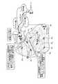
図8は、実施の形態2の通信システムにおいてゲートウェイ2Aが故障した場合の制御シーケンスの一例を示す図である。図8では、実施の形態1で示した図4,図7と同様に、通信ユニット3A1,3A2,3B1,3B2に関する制御のみを示している。FIG. 8 is a diagram illustrating an example of a control sequence when the
なお、上位サーバ1および各通信ユニット3は、実施の形態1と同様の情報(図5に示した情報など)を保持しているものとする。 It is assumed that the
本実施の形態の通信システムにおいて、上位サーバ1は、GWの故障を検出し、かつ故障GW(ゲートウェイ2A)配下の通信ユニット(ここでは通信ユニット3A2とする)に対して通信要求がある場合、故障しているGW2Aのアドホックネットワークに対する境界通信ユニットである通信ユニット3B2に対して、元々のメッセージ(GW2Aが故障していない場合にGW2A経由で送信するメッセージ)をカプセル化したメッセージを隣接GW2B経由で送信する(ステップS11)。In the communication system according to the present embodiment, the
図9は、カプセル化方法の一例を示す図であり、上段にカプセル化前のメッセージフォーマット(上位サーバ1から故障GW2A配下の通信ユニット3A2に向けて送信されるメッセージのフォーマット)、下段にカプセル化後のメッセージフォーマット(GW2Bから通信ユニット3B2に向けて送信されるメッセージのフォーマット)を示している。カプセル化前のメッセージ(GW2Aネットワーク転送用)においては、「送信先」には宛先となる通信ユニット(通信ユニット3A2)の識別情報が格納され、「送信元」にはカプセル化を解いて転送する通信ユニット(通信ユニット3B2)の識別情報が格納される。また、カプセル化後のメッセージ(GW2Bネットワーク転送用)においては、「送信先」にはカプセル化を解く通信ユニット(通信ユニット3B2)の識別情報が格納され、「送信元」にはカプセル化したメッセージの送信元となる上位サーバ1の識別情報が格納される。また、カプセル化後のメッセージには、故障GW情報として、故障GWの識別情報および無線チャネル情報が付加される。無線チャネル情報は、故障GWのアドホックネットワークで使用されている無線チャネルを示す。各通信ユニットが、隣接通信ユニットの接続先GWおよび使用無線チャネルの情報を保持している場合、故障GW情報内の「無線チャネル」は省略してもよい。なお、カプセル化されたメッセージは、上位サーバ1とゲートウェイ2Bの間の経路においては、所定のメディア変換等が実施されて転送される。FIG. 9 is a diagram showing an example of the encapsulation method. In the upper part, the message format before encapsulation (format of the message transmitted from the
ステップS11で送信されたメッセージ(カプセル化された要求メッセージ)を受信した各通信ユニット3は、GW2Bネットワーク転送用の「送信先」を確認して自装置宛のメッセージかどうかを確認し、他の装置宛であれば、保持している経路管理表に従って転送する。一方、自装置宛であれば、デカプセル処理を実行してカプセル化を解いた後、GW2Aネットワーク転送用の「送信先」が示す通信ユニットに向けて転送する。このとき、チャネル変更を行う。図8の例では、カプセル化された要求メッセージを受信した通信ユニット3B2がデカプセル処理を行い(ステップS12)、送信チャネルを故障GWのアドホックネットワークで使用されている無線チャネルxに変更する(ステップS13)。ここで、デカプセル処理を行った通信ユニット3B2は故障していないGW2Bのアドホックネットワークに参入中のため、通常は、他のGW(隣接GW)のアドホックネットワークに参入している通信ユニットへの経路管理表を有していない。そのため、通信ユニット3B2は、デカプセル化後の要求メッセージの宛先である通信ユニット3A2に向けて経路探索要求メッセージを送信し(ステップS14)、その応答(経路探索応答メッセージ)を受信して経路情報を取得する(ステップS15)。そして、この経路情報に従って、デカプセル化後の要求メッセージを送信する(ステップS16)。Each
通信ユニット3B2は、ステップS16で送信した要求メッセージに対する応答メッセージを受信すると(ステップS17)、上記のステップS13で変更したチャネルを元の無線チャネルyに戻すとともに、受信した応答メッセージをカプセル化してGW2B経由で上位サーバ1へ送信する(ステップS18,S19)。When the
なお、通信ユニット3B2にて通信ユニット3A2への経路を確立できない(経路探索要求に対する応答が受信できない)場合は、送信元の上位サーバ1に対してエラーを通知するか、上位サーバ1のタイムアウト処理(通信ユニット3B2はエラーを通知しない)にて送信失敗を判断する。When the
また、あらかじめ上位サーバ1では各通信ユニットの隣接情報(アドホックネットワーク内での転送経路の情報)を管理し、接続状態(アドホックネットワーク経路)から故障GW境界に接している通信ユニットとの接続可能性が高い通信ユニット(境界通信ユニット)を選択するようにしてもよい。これにより、不要かつ冗長経路なメッセージ送信を回避することが可能である。例えば、故障GWのアドホックネットワークに対して境界通信ユニットが複数存在する場合、要求メッセージの宛先通信ユニットまでの総ホップ数がより少なくなる境界通信ユニットを選択する。 In addition, the
また、上位サーバ1が、上記のステップS11で要求メッセージを送信するサーバ(例えばGWの故障検出機能を有さない業務サーバ)とGWの故障検出を行うサーバ(監視サーバ)の2つの装置によって構成されている場合、監視サーバは、GWの故障を検出すると、故障GWの情報、境界通信ユニット(カプセル化した要求メッセージの宛先とする通信ユニット)および使用チャネル(故障GWのアドホックネットワークで使用されている無線チャネル)の情報を業務サーバへ送信する。 The
このように、本実施の形態の通信システムにおいて、上位サーバは、故障GW配下の通信ユニットとの通信が必要となった場合、この通信ユニット宛のメッセージをカプセル化し、故障GWのアドホックネットワークに対する境界通信ユニット宛に送信し、カプセル化されたメッセージの宛先とされた境界通信ユニットは、受信したメッセージ(カプセル化されたメッセージ)から元の要求メッセージを取り出し、故障GWのアドホックネットワークで使用されている無線チャネルで送信することとした。また、境界通信ユニットは、故障GW配下の通信ユニットから応答メッセージを受信した場合には、カプセル化を行い、接続中のGWを介して上位サーバ宛に送信することとした。これにより、故障GW配下の通信ユニット群の接続先GWを切り替えさせることなく、これらの通信ユニット群と上位サーバとの通信を維持できる。 As described above, in the communication system according to the present embodiment, when communication with a communication unit under the fault GW is necessary, the upper server encapsulates a message addressed to the communication unit, and the boundary of the fault GW with respect to the ad hoc network. The boundary communication unit that is transmitted to the communication unit and is the destination of the encapsulated message extracts the original request message from the received message (encapsulated message) and is used in the ad hoc network of the failed GW. It was decided to transmit on the wireless channel. Further, when the boundary communication unit receives a response message from the communication unit under the faulty GW, the boundary communication unit performs encapsulation and transmits it to the upper server via the connected GW. Thereby, communication with these communication unit groups and a high-order server is maintainable, without switching the connecting point GW of the communication unit group under the malfunctioning GW.
なお、本実施の形態で説明した制御を実施の形態1で説明した制御を組み合わせて使用するようにしてもよい。例えば、上位サーバ1が通信ユニットと定期的に通信(メッセージの送受信)を行っている状態において、要求メッセージの送信タイミング(次の通信タイミング)に近いタイミングでGWの故障を検出し、この故障GW配下の通信ユニットの接続先変更のための制御(実施の形態1で説明した制御)を実行してしまうと定期的な通信が維持できない可能性がある場合には、本実施の形態で説明した制御を実施して定期的な通信を維持する。そして、通信終了後に故障GW配下の通信ユニットの接続先を切り替えさせる。 Note that the control described in the present embodiment may be used in combination with the control described in the first embodiment. For example, in a state in which the
実施の形態3.
実施の形態3の通信システムについて説明する。なお、システムの構成は、実施の形態1,2と同じもの(図1参照)として説明を行う。本実施の形態では、故障したGWが正常な状態に復帰した場合の制御動作について説明する。
A communication system according to the third embodiment will be described. The system configuration will be described assuming that it is the same as that of the first and second embodiments (see FIG. 1). In the present embodiment, a control operation when the failed GW returns to a normal state will be described.
図10は、実施の形態3の通信システムの動作例を示す図であり、故障していたGW2Aが正常動作に復帰した場合の動作例を示している。GW2Aが復帰する直前の状態は、通信ユニット3A1〜3A4,3B1〜3B5が全てGW2Bに接続しているものとする。また、3A1〜3A4は、GW2Aが故障する前は接続先をGW2Aとしており、GW2Aに接続していたときに使用していた管理情報(GW2Aの識別情報、使用無線チャネル情報、隣接通信ユニットの識別情報とその接続先GW情報、経路管理表、など)を保持しているものとする。FIG. 10 is a diagram illustrating an operation example of the communication system according to the third embodiment, and illustrates an operation example when the failed
本実施の形態の通信ユニットは、隣接GWの境界通信ユニットからゲートウェイ故障通知パケットを受信した場合、実施の形態1で説明した通信ユニットと同様の処理を実行して接続先のGWを切り替えるとともに、それまで接続していたGW(故障GW)に関する情報(GW識別子、使用無線チャネル、経路情報など)を一定期間保持しておく。 When the communication unit of the present embodiment receives a gateway failure notification packet from the boundary communication unit of the adjacent GW, the communication unit executes the same processing as the communication unit described in the first embodiment to switch the connection destination GW, Information (GW identifier, used radio channel, route information, etc.) related to the GW (failure GW) that has been connected so far is held for a certain period.
上位サーバ1は、故障GWが復旧したことを検出すると、ゲートウェイ復旧通知パケットを切替先GW群(故障GWに隣接している各GW)からブロードキャスト送信する。例えば、図10に示した例では、故障していたGW2Aに隣接しているゲートウェイ2Bからブロードキャストする。ゲートウェイ復旧通知パケットには復旧したGWのGW情報(GW識別子)を格納して送信する。GW識別子に加え、使用無線チャネル情報を格納してもよい。 When the
通信ユニットは、ゲートウェイ復旧通知パケットを受信した場合、復旧したGWが以前の接続先GWに該当するかどうか確認し、該当する場合には、受信したGW情報が示しているGW(復旧したGW)に対して再参入を通知する。このとき、保持していた経路管理表に従い、再参入通知のためのメッセージを送信する。復旧したGWが故障する前の情報を保持している場合、再参入通知のためのメッセージには、再参入を示す情報と送信元通信ユニットの識別情報とを設定して送信すればよい。復旧したGWが故障前の情報を保持していない場合には、再参入を示す情報と送信元通信ユニットの識別情報に加えて、復旧したGWが必要とする情報(例えば使用チャネル情報)を含んだメッセージを送信する。 When the communication unit receives the gateway recovery notification packet, the communication unit checks whether the recovered GW corresponds to the previous connection destination GW, and if so, the GW indicated by the received GW information (recovered GW) Is notified of re-entry. At this time, a message for re-entry notification is transmitted according to the stored route management table. When the recovered GW holds information before failure, information indicating re-entry and identification information of the transmission source communication unit may be set and transmitted in the message for re-entry notification. When the restored GW does not hold information before the failure, in addition to information indicating re-entry and identification information of the transmission source communication unit, information necessary for the restored GW (for example, used channel information) is included. Send a message.
図10は、故障から復旧したGWに隣接しているGWを経由して上位サーバ1がゲートウェイ復旧通知パケットを送信する場合の動作を示したものであるが、図11に示したように、復旧したGWを経由してゲートウェイ復旧通知パケットを送信するようにしてもよい。この場合、上位サーバ1は、復旧したGWに対して、ゲートウェイ復旧通知パケットを送信する無線チャネルを指示する。復旧したGWは、ゲートウェイ復旧通知パケットを受信した場合、上位サーバ1から指示された無線チャネル上にゲートウェイ復旧通知パケットをブロードキャスト送信する。ゲートウェイ復旧通知パケットを受信した通信ユニットの動作は図10の場合と同様である。 FIG. 10 shows the operation when the
図10,図11では、簡単化のために、復旧したGWの隣接GW(復旧したGWが故障前に収容していた通信ユニットを収容しているGW)が1台の場合について示したが、隣接GWが複数台存在する場合には、各隣接GW配下の通信ユニットに対してゲートウェイ復旧通知パケットを送信する。 In FIG. 10 and FIG. 11, for simplification, the case is shown in which the neighboring GW of the restored GW (the GW accommodating the communication unit accommodated before the failure by the restored GW) is one unit. When there are a plurality of adjacent GWs, a gateway restoration notification packet is transmitted to the communication units under each adjacent GW.
このように、本実施の形態の通信システムにおいて、上位サーバは、故障していたゲートウェイの復旧を検出した場合、その旨を示すゲートウェイ復旧通知パケットを、復旧したゲートウェイに隣接しているゲートウェイ配下の通信ユニットに向けて送信し、通信ユニットは、以前接続していたゲートウェイが復旧した旨の通知を受けると、復旧したゲートウェイに接続先を切り替える(元に戻す)こととした。これにより、復旧したGWの周囲のGW(隣接GW)配下の通信ユニットの接続先を、復旧したGWに速やかに切り替えることができる。加えて、GW間の負荷分散を実現できる。 As described above, in the communication system according to the present embodiment, when the upper server detects the restoration of the failed gateway, the gateway restoration notification packet indicating the failure is sent to the gateway under the gateway adjacent to the restored gateway. When the communication unit receives the notification that the previously connected gateway has been restored, the communication unit switches (restores) the connection destination to the restored gateway. Thereby, the connection destination of the communication unit under GW (adjacent GW) around the restored GW can be quickly switched to the restored GW. In addition, load distribution between GWs can be realized.
以上のように、本発明にかかる通信システムは、アドホック通信を適用した自動検針システム(ガス・水道・電力といった各種検針業務)に有用であり、特に、需要家に設置された通信ユニットを収容するゲートウェイが故障した場合においても検針動作の早期復旧が可能な自動検針システムに適している。 As described above, the communication system according to the present invention is useful for an automatic meter reading system (various meter reading operations such as gas, water and electric power) to which ad hoc communication is applied, and particularly accommodates a communication unit installed in a consumer. It is suitable for an automatic meter reading system that enables early recovery of meter reading operation even when the gateway fails.
1 上位サーバ
2A,2B ゲートウェイ(GW)
3A1,3A2,3A3,3A4,3B1,3B2,3B3,3B4,3B5, 通信ユニット
31 無線インタフェイス(I/F)
32 送受信部
33 経路制御部
34 ゲートウェイ/無線チャネル切替処理部
35 隣接機器情報記憶部
36 ユニット制御部
37 他ユニットインタフェイス(I/F)
38 各種ユニット1
3A1 , 3A2 , 3A3 , 3A4 , 3B1 , 3B2 , 3B3 , 3B4 , 3B5 ,
32 Transmission /
38 Various units
Claims (17)
Translated fromJapanese前記監視サーバは、前記通信ユニットそれぞれについて、直接通信が可能な通信ユニットである隣接通信ユニットとその接続先ゲートウェイの情報を収集・管理し、ゲートウェイの故障を検出した場合、当該検出したゲートウェイに接続中の通信ユニットと直接通信が可能な位置に存在し、かつ当該検出したゲートウェイとは異なるゲートウェイに接続中の通信ユニットである境界通信ユニットを介して、故障したゲートウェイの識別情報を含む信号を、当該検出したゲートウェイに接続中の通信ユニットへ送信する、
ことを特徴とする通信システム。A plurality of ad hoc communication networks formed by a gateway and a communication unit accommodated in the gateway, and a monitoring server that monitors the gateway of each ad hoc communication network
For each of the communication units, the monitoring server collects and manages information of adjacent communication units that are direct communication units and their connection destination gateways, and if a gateway failure is detected, the monitoring server connects to the detected gateway. The signal including the identification information of the failed gateway is present through a boundary communication unit that is a communication unit that is connected to a gateway different from the detected gateway, and exists in a position where direct communication with the communication unit in Send to the communication unit connected to the detected gateway,
A communication system characterized by the above.
アドホック通信ネットワークへの参入が完了した場合、または、前記監視サーバから要求を受けた場合、接続中のゲートウェイを示す第1の識別情報および隣接通信ユニットを示す第2の識別情報を前記監視サーバへ送信し、
前記監視サーバは、
前記第1の識別情報および前記第2の識別情報を受信した場合、受信した各情報を、当該情報の送信元通信ユニットを示す第3の識別情報とともに記憶し、
ゲートウェイの故障を検出した場合、前記第1の識別情報、前記第2の識別情報および前記第3の識別情報に基づいて、前記境界通信ユニットに該当する通信ユニットを選択し、さらに、当該選択した通信ユニットに対して指示を行い、前記故障したゲートウェイの識別情報を含む信号である故障ゲートウェイ通知信号を当該検出したゲートウェイである故障ゲートウェイに接続中の通信ユニットに向けてブロードキャスト送信させる、
ことを特徴とする請求項1に記載の通信システム。The communication unit is
When entry into the ad hoc communication network is completed or when a request is received from the monitoring server, the first identification information indicating the connected gateway and the second identification information indicating the adjacent communication unit are sent to the monitoring server. Send
The monitoring server is
When the first identification information and the second identification information are received, each received information is stored together with third identification information indicating a transmission source communication unit of the information,
When a gateway failure is detected, a communication unitcorresponding to the boundary communication unit is selected based on the first identification information, the second identification information, and the third identification information, and the selected An instruction is given to the communication unit, and a failure gateway notification signal that is a signal including identification information of the failed gateway is broadcasted to the communication unit connected to the detected failure gateway that is the detected gateway.
The communication system according to claim 1.
前記選択した通信ユニットに対して、前記故障ゲートウェイ通知信号の最大ホップ数を指定し、
前記指示を受けた通信ユニットは、
指定された最大ホップ数を設定して前記故障ゲートウェイ通知信号をブロードキャスト送信する、
ことを特徴とする請求項2に記載の通信システム。The monitoring server is
Specify the maximum number of hops of the failed gateway notification signal for the selected communication unit,
The communication unit that has received the instruction
Broadcast the failure gateway notification signal by setting the specified maximum number of hops;
The communication system according to claim 2.
前記境界通信ユニットに該当し、かつそれぞれ異なるゲートウェイに接続中の複数の通信ユニットが存在する場合、当該複数の通信ユニットから前記故障ゲートウェイ通知信号をブロードキャスト送信させる、
ことを特徴とする請求項2または3に記載の通信システム。The monitoring server is
When there are a plurality of communication unitscorresponding to the boundary communication unitand connected to different gateways, the failure gateway notification signal is broadcasted from the plurality of communication units.
The communication system according to claim 2 or 3, wherein
前記第1の識別情報、前記第2の識別情報および前記第3の識別情報に基づいて前記故障ゲートウェイに接続中の通信ユニットの新たな接続先のゲートウェイを決定し、当該決定結果を前記選択した通信ユニットに通知し、
前記決定結果が通知された通信ユニットは、
前記新たな接続先のゲートウェイの情報を前記故障ゲートウェイ通知信号に含めてブロードキャスト送信する、
ことを特徴とする請求項2、3または4に記載の通信システム。The monitoring server is
Based on the first identification information, the second identification information, and the third identification information, a gateway of a new connection destination of a communication unit connected to the failed gateway is determined, and the determination result is selected. Notify the communication unit,
The communication unit notified of the determination result is
Broadcast information including the new connection destination gateway information included in the failure gateway notification signal,
The communication system according to claim 2, 3, or 4.
前記第1の識別情報、前記第2の識別情報および前記第3の識別情報に基づいて前記故障ゲートウェイに接続中の通信ユニットが新たな接続先を検索する際の検索対象無線チャネルを決定し、当該決定結果を前記選択した通信ユニットに通知し、
前記決定結果が通知された通信ユニットは、
前記検索対象無線チャネルの情報を前記故障ゲートウェイ通知信号に含めてブロードキャスト送信する、
ことを特徴とする請求項2、3または4に記載の通信システム。The monitoring server is
Determining a search target radio channel when a communication unit connected to the failed gateway searches for a new connection destination based on the first identification information, the second identification information, and the third identification information; Notify the selected communication unit to the selected communication unit,
The communication unit notified of the determination result is
Broadcast information including the information of the search target wireless channel included in the failure gateway notification signal,
The communication system according to claim 2, 3, or 4.
前記アドホック通信ネットワークへの参入動作において、各隣接通信ユニットから、隣接通信ユニットが接続しているゲートウェイの識別情報を取得し、当該識別情報と、当該識別情報を取得する際の通信で使用した無線チャネルを示す使用チャネル情報とを記憶し、
前記故障ゲートウェイ通知信号のブロードキャスト送信指示を受けた場合、前記故障ゲートウェイに接続中の隣接通信ユニットが使用している無線チャネル上へ、当該故障ゲートウェイ通知信号をブロードキャスト送信する、
ことを特徴とする請求項2〜6のいずれか一つに記載の通信システム。The communication unit is
In the entry operation to the ad hoc communication network, the identification information of the gateway to which the adjacent communication unit is connected is acquired from each adjacent communication unit, and the identification information and the wireless used for communication when acquiring the identification information Storing used channel information indicating the channel,
When receiving a broadcast transmission instruction of the failed gateway notification signal, the failure gateway notification signal is broadcasted on a wireless channel used by an adjacent communication unit connected to the failed gateway.
The communication system according to any one of claims 2 to 6, wherein:
前記選択した通信ユニットに対して前記故障ゲートウェイ通知信号をユニキャスト送信し、
前記通信ユニットは、
自装置宛にユニキャスト送信されてきた故障ゲートウェイ通知信号を受信した場合、当該受信した故障ゲートウェイ通知信号をブロードキャスト転送する、
ことを特徴とする請求項7に記載の通信システム。The monitoring server is
Unicasting the failed gateway notification signal to the selected communication unit;
The communication unit is
When the failure gateway notification signal that has been unicast transmitted to the device itself is received, the received failure gateway notification signal is broadcasted.
The communication system according to claim 7.
接続中のゲートウェイの識別情報を含んだ故障ゲートウェイ通知信号を受信した場合、接続先ゲートウェイの再選択動作を実行する、
ことを特徴とする請求項2〜8のいずれか一つに記載の通信システム。The communication unit is
When a failure gateway notification signal including identification information of the connected gateway is received, a reselection operation of the connection destination gateway is executed.
The communication system according to any one of claims 2 to 8.
接続中のゲートウェイの識別情報を含んだ故障ゲートウェイ通知信号を受信してから一定時間が経過後、前記再選択動作を開始する、
ことを特徴とする請求項9に記載の通信システム。The communication unit is
The reselection operation is started after a predetermined time has elapsed since the failure gateway notification signal including the identification information of the connected gateway is received.
The communication system according to claim 9.
ことを特徴とする請求項10に記載の通信システム。The fixed time is a time determined based on thenumber of transfer hops from the communication unit that first transmitted the failure gateway notification signal to theown communication unit ,
The communication system according to claim 10.
接続中のゲートウェイの識別情報を含んだ故障ゲートウェイ通知信号を受信して接続先ゲートウェイを切り替えた場合、それまで接続していたゲートウェイである故障ゲートウェイの情報を記憶しておき、その後、当該故障ゲートウェイが復旧したことを示す信号を受信した場合には、接続先を当該復旧したゲートウェイに戻す、
ことを特徴とする請求項2〜11のいずれか一つに記載の通信システム。The communication unit is
When the failure gateway notification signal including the identification information of the connected gateway is received and the connection destination gateway is switched, the information of the failure gateway which is the gateway connected so far is stored, and then the failure gateway concerned If a signal indicating that has been restored is received, return the connection destination to the restored gateway.
The communication system according to any one of claims 2 to 11, characterized in that:
前記故障ゲートウェイの復旧を検知した場合、当該復旧したゲートウェイが故障する前に当該ゲートウェイに接続していた各通信ユニットが現在使用している無線チャネルを当該ゲートウェイに通知し、
前記復旧したゲートウェイは、
前記通知内容が示す無線チャネル上に、復旧したことを示す信号をブロードキャスト送信する、
ことを特徴とする請求項12に記載の通信システム。The monitoring server is
When the recovery of the failed gateway is detected, the wireless channel currently used by each communication unit connected to the gateway before the recovered gateway breaks down is notified to the gateway,
The restored gateway is
Broadcasting a signal indicating recovery on the wireless channel indicated by the notification content;
The communication system according to claim 12.
前記通信ユニットと定期的に通信を行っている状態においてゲートウェイの故障を検出し、かつ故障検出時刻と前記定期的な通信の次の実行時刻の差が所定値未満の場合、
前記故障を検出したゲートウェイに接続中の通信ユニットと行う次の定期的な通信においては、前記選択した通信ユニット経由で通信を行う、
ことを特徴とする請求項2〜13のいずれか一つに記載の通信システム。The monitoring server is
When a gateway failure is detected in a state where the communication unit is regularly communicating with the communication unit, and the difference between the failure detection time and the next execution time of the periodic communication is less than a predetermined value,
In the next periodic communication performed with the communication unit connected to the gateway that has detected the failure, communication is performed via the selected communication unit.
The communication system according to any one of claims2 to 13, characterized by:
前記選択した通信ユニットに対して、前記次の定期的な通信における通信相手先通信ユニット宛のメッセージをカプセル化するとともに故障ゲートウェイの情報を付加して送信し、
前記故障ゲートウェイの情報が付加されたカプセル化メッセージを受信した通信ユニットは、デカプセル化を行い、故障ゲートウェイに接続中の隣接通信ユニットが使用している無線チャネル上へ転送する、
ことを特徴とする請求項14に記載の通信システム。The monitoring server is
To the selected communication unit, encapsulates a message addressed to the communication partner communication unit in the next periodic communication and adds the information of the failed gateway, and transmits it.
The communication unit that has received the encapsulated message with the information of the failed gateway decapsulates and transfers it onto the wireless channel used by the adjacent communication unit connected to the failed gateway.
The communication system according to claim 14.
前記通信ユニット経由で需要家の電気、ガスまたは水道の検針データを収集する業務サーバと、
を備えることを特徴とする自動検針システム。A communication system according to any one of claims 1 to 15;
A business server that collects electricity, gas or water meter reading data of consumers via the communication unit;
An automatic meter reading system comprising:
前記通信ユニットそれぞれについて、直接通信が可能な通信ユニットである隣接通信ユニットとその接続先ゲートウェイの情報を収集・管理し、ゲートウェイの故障を検出した場合、当該検出したゲートウェイに接続中の通信ユニットと直接通信が可能な位置に存在し、かつ当該検出したゲートウェイとは異なるゲートウェイに接続中の通信ユニットである境界通信ユニットを介して、故障したゲートウェイの識別情報を含む信号を、当該検出したゲートウェイに接続中の通信ユニットへ送信する、 For each of the communication units, information on the adjacent communication unit that is a communication unit capable of direct communication and its connected gateway is collected and managed, and when a failure of the gateway is detected, the communication unit connected to the detected gateway and A signal including the identification information of the failed gateway is sent to the detected gateway through a boundary communication unit that is a communication unit that is connected to a gateway different from the detected gateway. Send to the connected communication unit,
ことを特徴とする監視サーバ。 A monitoring server characterized by that.
Priority Applications (1)
| Application Number | Priority Date | Filing Date | Title |
|---|---|---|---|
| JP2011124377AJP5709649B2 (en) | 2011-06-02 | 2011-06-02 | Communication system, automatic meter reading system and monitoring server |
Applications Claiming Priority (1)
| Application Number | Priority Date | Filing Date | Title |
|---|---|---|---|
| JP2011124377AJP5709649B2 (en) | 2011-06-02 | 2011-06-02 | Communication system, automatic meter reading system and monitoring server |
Publications (2)
| Publication Number | Publication Date |
|---|---|
| JP2012253554A JP2012253554A (en) | 2012-12-20 |
| JP5709649B2true JP5709649B2 (en) | 2015-04-30 |
Family
ID=47525953
Family Applications (1)
| Application Number | Title | Priority Date | Filing Date |
|---|---|---|---|
| JP2011124377AActiveJP5709649B2 (en) | 2011-06-02 | 2011-06-02 | Communication system, automatic meter reading system and monitoring server |
Country Status (1)
| Country | Link |
|---|---|
| JP (1) | JP5709649B2 (en) |
Families Citing this family (8)
| Publication number | Priority date | Publication date | Assignee | Title |
|---|---|---|---|---|
| JP5942734B2 (en)* | 2012-09-20 | 2016-06-29 | 沖電気工業株式会社 | Data collection system, data collection method, adjacent information management server, and program |
| JP6008761B2 (en)* | 2013-03-07 | 2016-10-19 | 株式会社日立製作所 | Independent distributed network system |
| JP6191411B2 (en)* | 2013-11-15 | 2017-09-06 | 富士通株式会社 | Node device, control program, and operation method of node device |
| WO2015174112A1 (en)* | 2014-05-15 | 2015-11-19 | ソニー株式会社 | Terminal device, system, information presentation method, and program |
| JP2016148973A (en)* | 2015-02-12 | 2016-08-18 | 日本電信電話株式会社 | Life-and-death monitoring device, life-and-death monitoring system, life-and-death monitoring method, and life-and-death monitoring method program |
| JP6579940B2 (en)* | 2015-12-18 | 2019-09-25 | シャープ株式会社 | Radio telemeter system and radio |
| JP6845127B2 (en)* | 2017-12-25 | 2021-03-17 | 日本電信電話株式会社 | External monitoring system and monitoring terminal |
| US20190349277A1 (en)* | 2018-05-08 | 2019-11-14 | Landis+Gyr Innovations, Inc. | Information element to indicate loss of backhaul connection |
Family Cites Families (4)
| Publication number | Priority date | Publication date | Assignee | Title |
|---|---|---|---|---|
| WO2006048936A1 (en)* | 2004-11-05 | 2006-05-11 | Mitsubishi Denki Kabushiki Kaisha | Ad hoc network, mobile terminal, gateway node, and method for selecting gateway node |
| JP5085282B2 (en)* | 2007-11-06 | 2012-11-28 | 関西電力株式会社 | RADIO COMMUNICATION SYSTEM, INFORMATION COMMUNICATION SYSTEM USING THE SAME, AND POWER SUPPLY MONITORING / CONTROL SYSTEM |
| JP5297220B2 (en)* | 2009-02-13 | 2013-09-25 | 三菱電機株式会社 | Automatic meter reading radio system and radio communication terminal device used therefor |
| JP4846812B2 (en)* | 2009-02-23 | 2011-12-28 | 関西電力株式会社 | Wireless communication system |
- 2011
- 2011-06-02JPJP2011124377Apatent/JP5709649B2/enactiveActive
Also Published As
| Publication number | Publication date |
|---|---|
| JP2012253554A (en) | 2012-12-20 |
Similar Documents
| Publication | Publication Date | Title |
|---|---|---|
| JP5709649B2 (en) | Communication system, automatic meter reading system and monitoring server | |
| US9686739B2 (en) | Method of establishing smart architecture cell mesh (SACM) network | |
| JP5297220B2 (en) | Automatic meter reading radio system and radio communication terminal device used therefor | |
| JP5159991B1 (en) | Communication system and automatic meter reading system | |
| JP5836477B2 (en) | Data communication apparatus, data communication system, and data communication method | |
| CN109845332A (en) | Mobile device relay services for reliable Internet of Things | |
| KR102047848B1 (en) | Restoration Methods of IoT Control Networks and Systems Thereof | |
| CN105191224A (en) | Dynamic lte network | |
| JP2009302694A (en) | Radio communication network system | |
| JP2015037208A (en) | Communication device, communication system, communication control method, and communication control program | |
| WO2016203553A1 (en) | Satellite communication device, management device, monitoring system, and monitoring method | |
| Aydeger et al. | SDN-enabled recovery for Smart Grid teleprotection applications in post-disaster scenarios | |
| CN103636171A (en) | Communication apparatus and communication system | |
| JP7316909B2 (en) | Optical communication system, communication device and communication method | |
| JP5183689B2 (en) | Wireless communication system, wireless communication device, and wireless communication method | |
| TWI792875B (en) | Communication system, hub device, central device, terminal, communication method, and recording medium | |
| WO2016013979A1 (en) | Routing protocol for advanced metering infrastructure system | |
| JP5853227B2 (en) | Multi-hop communication method, multi-hop communication system, and communication terminal | |
| JP4767329B2 (en) | Network system and communication method | |
| EP2244428B1 (en) | Communication apparatus for transmitting data through a plurality of data-paths | |
| JP5870286B2 (en) | Multi-hop communication method, multi-hop communication system, and communication terminal | |
| JP2013243485A (en) | Communication terminal and multi-hop communication system | |
| WO2015045306A1 (en) | Femto gateway and femto gateway control method | |
| JP4692419B2 (en) | Network device, redundant switching method used therefor, and program thereof | |
| JP2023007686A (en) | Wireless network device and information collection method for wireless network device |
Legal Events
| Date | Code | Title | Description |
|---|---|---|---|
| A621 | Written request for application examination | Free format text:JAPANESE INTERMEDIATE CODE: A621 Effective date:20140106 | |
| A977 | Report on retrieval | Free format text:JAPANESE INTERMEDIATE CODE: A971007 Effective date:20140722 | |
| A131 | Notification of reasons for refusal | Free format text:JAPANESE INTERMEDIATE CODE: A131 Effective date:20140729 | |
| A521 | Request for written amendment filed | Free format text:JAPANESE INTERMEDIATE CODE: A523 Effective date:20140926 | |
| TRDD | Decision of grant or rejection written | ||
| A01 | Written decision to grant a patent or to grant a registration (utility model) | Free format text:JAPANESE INTERMEDIATE CODE: A01 Effective date:20150203 | |
| A61 | First payment of annual fees (during grant procedure) | Free format text:JAPANESE INTERMEDIATE CODE: A61 Effective date:20150303 | |
| R150 | Certificate of patent or registration of utility model | Ref document number:5709649 Country of ref document:JP Free format text:JAPANESE INTERMEDIATE CODE: R150 | |
| R250 | Receipt of annual fees | Free format text:JAPANESE INTERMEDIATE CODE: R250 | |
| R250 | Receipt of annual fees | Free format text:JAPANESE INTERMEDIATE CODE: R250 | |
| R250 | Receipt of annual fees | Free format text:JAPANESE INTERMEDIATE CODE: R250 | |
| R250 | Receipt of annual fees | Free format text:JAPANESE INTERMEDIATE CODE: R250 | |
| R250 | Receipt of annual fees | Free format text:JAPANESE INTERMEDIATE CODE: R250 | |
| R250 | Receipt of annual fees | Free format text:JAPANESE INTERMEDIATE CODE: R250 | |
| R250 | Receipt of annual fees | Free format text:JAPANESE INTERMEDIATE CODE: R250 | |
| R250 | Receipt of annual fees | Free format text:JAPANESE INTERMEDIATE CODE: R250 |