JP5706347B2 - Redundant control system - Google Patents
Redundant control systemDownload PDFInfo
- Publication number
- JP5706347B2 JP5706347B2JP2012013377AJP2012013377AJP5706347B2JP 5706347 B2JP5706347 B2JP 5706347B2JP 2012013377 AJP2012013377 AJP 2012013377AJP 2012013377 AJP2012013377 AJP 2012013377AJP 5706347 B2JP5706347 B2JP 5706347B2
- Authority
- JP
- Japan
- Prior art keywords
- tracking
- control
- signal
- control device
- bus
- Prior art date
- Legal status (The legal status is an assumption and is not a legal conclusion. Google has not performed a legal analysis and makes no representation as to the accuracy of the status listed.)
- Active
Links
Images


Classifications
- G—PHYSICS
- G06—COMPUTING OR CALCULATING; COUNTING
- G06F—ELECTRIC DIGITAL DATA PROCESSING
- G06F11/00—Error detection; Error correction; Monitoring
- G06F11/30—Monitoring
- G06F11/3003—Monitoring arrangements specially adapted to the computing system or computing system component being monitored
- G06F11/3027—Monitoring arrangements specially adapted to the computing system or computing system component being monitored where the computing system component is a bus
- G—PHYSICS
- G05—CONTROLLING; REGULATING
- G05B—CONTROL OR REGULATING SYSTEMS IN GENERAL; FUNCTIONAL ELEMENTS OF SUCH SYSTEMS; MONITORING OR TESTING ARRANGEMENTS FOR SUCH SYSTEMS OR ELEMENTS
- G05B15/00—Systems controlled by a computer
- G05B15/02—Systems controlled by a computer electric
- G—PHYSICS
- G06—COMPUTING OR CALCULATING; COUNTING
- G06F—ELECTRIC DIGITAL DATA PROCESSING
- G06F11/00—Error detection; Error correction; Monitoring
- G06F11/07—Responding to the occurrence of a fault, e.g. fault tolerance
- G06F11/16—Error detection or correction of the data by redundancy in hardware
- G06F11/20—Error detection or correction of the data by redundancy in hardware using active fault-masking, e.g. by switching out faulty elements or by switching in spare elements
- G06F11/2002—Error detection or correction of the data by redundancy in hardware using active fault-masking, e.g. by switching out faulty elements or by switching in spare elements where interconnections or communication control functionality are redundant
- G06F11/2007—Error detection or correction of the data by redundancy in hardware using active fault-masking, e.g. by switching out faulty elements or by switching in spare elements where interconnections or communication control functionality are redundant using redundant communication media
- G—PHYSICS
- G06—COMPUTING OR CALCULATING; COUNTING
- G06F—ELECTRIC DIGITAL DATA PROCESSING
- G06F11/00—Error detection; Error correction; Monitoring
- G06F11/07—Responding to the occurrence of a fault, e.g. fault tolerance
- G06F11/16—Error detection or correction of the data by redundancy in hardware
- G06F11/20—Error detection or correction of the data by redundancy in hardware using active fault-masking, e.g. by switching out faulty elements or by switching in spare elements
- G06F11/202—Error detection or correction of the data by redundancy in hardware using active fault-masking, e.g. by switching out faulty elements or by switching in spare elements where processing functionality is redundant
- G06F11/2038—Error detection or correction of the data by redundancy in hardware using active fault-masking, e.g. by switching out faulty elements or by switching in spare elements where processing functionality is redundant with a single idle spare processing component
- G—PHYSICS
- G06—COMPUTING OR CALCULATING; COUNTING
- G06F—ELECTRIC DIGITAL DATA PROCESSING
- G06F11/00—Error detection; Error correction; Monitoring
- G06F11/07—Responding to the occurrence of a fault, e.g. fault tolerance
- G06F11/16—Error detection or correction of the data by redundancy in hardware
- G06F11/20—Error detection or correction of the data by redundancy in hardware using active fault-masking, e.g. by switching out faulty elements or by switching in spare elements
- G06F11/2097—Error detection or correction of the data by redundancy in hardware using active fault-masking, e.g. by switching out faulty elements or by switching in spare elements maintaining the standby controller/processing unit updated
Landscapes
- Engineering & Computer Science (AREA)
- Theoretical Computer Science (AREA)
- Physics & Mathematics (AREA)
- General Engineering & Computer Science (AREA)
- General Physics & Mathematics (AREA)
- Quality & Reliability (AREA)
- Computing Systems (AREA)
- Mathematical Physics (AREA)
- Automation & Control Theory (AREA)
- Safety Devices In Control Systems (AREA)
- Hardware Redundancy (AREA)
Description
Translated fromJapanese本発明は、一方を待機系、他方を常用系として運転する二重化制御システムおよびその制御方法に関する。 The present invention relates to a duplex control system in which one is operated as a standby system and the other as a regular system, and a control method therefor.
原子力発電所をはじめとする発電プラントを監視、制御する制御システムは一般に2つの制御装置によって二重化構成され、一方を常用系、他方を待機系として運転している。この二重化制御システムは、2つの制御装置を内部専用バスによって接続する。2つの制御装置は、各々の活死、故障情報ならびに演算結果や時刻情報等を示すトラッキング信号を内部専用バスをトラッキングバスとして交換し、互いに相手系の制御装置の状態確認を行うとともに、演算結果や時刻情報を更新して同期を図っている。 A control system for monitoring and controlling a power plant such as a nuclear power plant is generally configured in a duplex manner by two control devices, one of which is operated as a regular system and the other is operated as a standby system. This duplex control system connects two control devices by an internal dedicated bus. The two control devices exchange the tracking signals indicating the life and failure information, calculation results, time information, etc., with the internal dedicated bus as the tracking bus, and mutually check the status of the partner control device and the calculation results. And time information is updated to synchronize.
二重化制御システムは、常用系の制御装置に異常が発生した場合、内部専用バスを通じて待機系の制御装置に異常発生を通知し、待機系を常用系に切り替えて運転を継続させている。この系切り替えは、内部専用バスによって常用系、待機系のステータスを交換するとともに、内部専用バス内のフリップフロップ回路によって何れか一方を常用系、他方を待機系として設定することで、両系が常用系になることを防止する技術が開発されている(例えば特許文献1参照)。また、二重化制御システムの各制御装置内の系切替部をマスタとスレーブとからなる二重構成にして、待機系と常用系の系切替を冗長化させる技術が開発されている(例えば特許文献2参照)。 In the case where an abnormality occurs in the normal control device, the duplex control system notifies the standby control device of the abnormality through the internal dedicated bus and switches the standby system to the normal system to continue the operation. In this system switching, the statuses of the active system and the standby system are exchanged by the internal dedicated bus, and either system is set as the normal system and the other is set as the standby system by the flip-flop circuit in the internal dedicated bus. A technique for preventing the system from becoming a regular system has been developed (see, for example, Patent Document 1). In addition, a technology has been developed in which a system switching unit in each control device of a duplex control system is configured to have a dual configuration composed of a master and a slave so that system switching between a standby system and an active system is made redundant (for example, Patent Document 2). reference).
上述した特許文献1に記載の技術は、内部専用バスからの制御装置の抜け、または内部専用バス内の断線等によってトラッキングバスの異常が生じ、内部専用バスを流れるトラッキング信号が途絶えた場合、内部専用バス自身がトラッキング信号の断絶を検知して各制御装置に通知する機能を有する。この機能によって二重化制御システムの各制御装置は、トラッキング信号の断絶が他系の制御装置の送信異常によるものではなく、トラッキングバスの異常によるものであることを認識し、運転を継続することができる
しかしながら、汎用のパーソナルコンピュータやコントローラを制御装置に適用し、イーサネット(登録商標)等の汎用伝送手段をトラッキングバスとして接続して二重化制御システムを構成したとき、トラッキングバスのコネクタ抜けまたは断線といったトラッキング信号断絶事象が発生した場合に、トラッキングバス自身はこの信号断絶事象を検出する機能を有していない。The technique described in Patent Document 1 described above is based on the fact that a tracking bus abnormality occurs due to disconnection of the control device from the internal dedicated bus or disconnection in the internal dedicated bus, and the tracking signal flowing through the internal dedicated bus is interrupted. The dedicated bus itself has a function of detecting the disconnection of the tracking signal and notifying each control device. With this function, each control device of the redundant control system can continue operation by recognizing that the disconnection of the tracking signal is not caused by the transmission abnormality of the control device of the other system but the abnormality of the tracking bus. However, when a dual-purpose control system is configured by applying a general-purpose personal computer or controller to the control device and connecting general-purpose transmission means such as Ethernet (registered trademark) as a tracking bus, a tracking signal such as connector disconnection or disconnection of the tracking bus When a disconnection event occurs, the tracking bus itself does not have a function of detecting this signal disconnection event.
したがって、両制御装置はトラッキング信号の断絶が相手系の制御装置の異常によるものであるか、トラッキングバスの異常によるものであるかを認識できない。結果、両系の制御装置は正常動作しているにも関わらず、互いに相手系が異常と判断して両系が一重常用に遷移し、二つの制御装置が同じ制御対象に対して制御を行い、誤動作を誘発する可能性がある。上述した特許文献2に記載の技術においても、二重化した切替部の両方でトラッキングを行うことができない事象が発生した場合、同様の誤動作の可能性がある。 Therefore, the two control devices cannot recognize whether the tracking signal disconnection is caused by an abnormality of the counterpart control device or an abnormality of the tracking bus. As a result, although the control devices of both systems are operating normally, the other system determines that the other system is abnormal, and both systems transition to single use, and the two control devices control the same controlled object. , May cause malfunction. Even in the technique described in
そこで本発明は、各制御装置がトラッキングバスにおける伝送異常を探知することができる二重化制御システムを提供することを目的とする。 Therefore, an object of the present invention is to provide a duplex control system in which each control device can detect a transmission abnormality in a tracking bus.
上記目的を達成するために、本発明の二重化制御システムは、一方を待機系、他方を常用系として設定して運転する2つの制御装置と、2つの制御装置を接続し、2つの制御装置間でトラッキング信号を送受信させることができるトラッキングバスと、2つの制御装置に接続され、2つの制御装置の演算情報を伝送する制御用伝送路とを備え、2つの制御装置は、自系の状態判定を行い、この状態判定結果をトラッキング信号としてトラッキングバスを介して他系の制御装置に送信する自系状態判定部と、他系の制御装置からトラッキングバスを介してトラッキング信号を受信し、他系の制御装置の状態確認を行う他系信号確認部と、この他系信号確認部においてトラッキング信号を受信できない場合に、自系状態判定部にトラッキング信号を制御用伝送路を介して他系の他系信号確認部に送信させる伝送路切替部とを各々有することを特徴とする。 In order to achieve the above object, the duplex control system of the present invention connects two control devices that operate with one set as a standby system and the other as a regular system, and connects the two control devices. A tracking bus that can transmit and receive tracking signals and a control transmission line that is connected to two control devices and transmits computation information of the two control devices, and the two control devices determine their own system status. The system status determination unit that transmits the status determination result as a tracking signal to the other system control device via the tracking bus, and receives the tracking signal from the other system control device via the tracking bus. The other system signal confirmation unit for confirming the status of the control device and the tracking signal to the own system state determination unit when the other system signal confirmation unit cannot receive the tracking signal. Through the control transmission channel and having each a transmission line switching unit for transmitting to another system signal confirmation section of the other system.
さらに上記目的を達成するために、本発明の二重化制御システムの制御方法は、自系の制御装置の状態判定を行い、この状態判定結果をトラッキング信号としてトラッキングバスを介して他系の制御装置に送信する工程と、他系の制御装置からトラッキングバスを介してトラッキング信号を受信し、他系の制御装置の状態確認を行う工程と、トラッキング信号を受信できない場合に、自系状態判定部にトラッキング信号を2つの制御装置の演算情報の伝送路となる制御用伝送路を介して他系の他系信号確認部に送信させる工程とを備えることを特徴とする。 Furthermore, in order to achieve the above object, the control method of the duplex control system according to the present invention performs the state determination of the control device of the own system, and uses this state determination result as a tracking signal to the control device of the other system via the tracking bus. The process of transmitting, receiving the tracking signal from the control device of the other system via the tracking bus, checking the status of the control device of the other system, and tracking to the own system state determination unit when the tracking signal cannot be received And a step of transmitting the signal to the other system signal confirmation unit of the other system via a control transmission path serving as a transmission path for calculation information of the two control devices.
本発明によれば、二重化制御システムの各制御装置がトラッキングバスにおける伝送異常を探知することができる。 According to the present invention, each control device of the redundant control system can detect a transmission abnormality in the tracking bus.
以下、本発明の実施形態を説明する。 Embodiments of the present invention will be described below.
(第1の実施形態)
(構成)
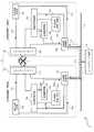
以下、本発明の第1の実施形態に係る二重化制御システムについて図1乃至図3を参照して説明する。図1は、本発明の第1の実施形態に係る二重化制御システムのトラッキングバス正常時の動作を示す概略構成図である。(First embodiment)
(Constitution)
The duplex control system according to the first embodiment of the present invention will be described below with reference to FIGS. FIG. 1 is a schematic configuration diagram showing the operation of the duplex control system according to the first embodiment of the present invention when the tracking bus is normal.
二重化制御システム1は、制御装置2と、トラッキングバス3と、制御用伝送路4とから構成される。制御装置2は、A系制御装置2aと、B系制御装置2bとから構成される、また、制御用伝送路4にはエンジニアリング装置5が接続される。 The duplex control system 1 includes a
A系制御装置2a、B系制御装置2bは、それぞれ自系状態判定部11a、11bと、トラッキングバスインターフェイス(IF)12a、12bと、他系信号確認部13a、13bと、伝送路切替部14a、14bと、系切替部15a、15bと、制御用伝送路インターフェイス(IF)16a、16bとを有する。 The
トラッキングバスIF12aとトラッキングバスIF12bは、トラッキングバス3によって接続される。トラッキングバス3には、イーサネット(登録商標)やfirewire(登録商標)、IEEE1394等の汎用の伝送手段を適用することができる。 The tracking bus IF 12a and the tracking bus IF 12b are connected by the
図1に示すように、自系状態判定部11a、11bは、トラッキング信号21a、21bをトラッキングバスIF12a、12bに送信することができるように接続される。他系信号確認部13a、13bは、他系のトラッキング信号21a、21bをトラッキングバスIF12a、12bを介して受信することができるように接続される。伝送路切替部14a、14bは、伝送指令22a、22bをトラッキングバスIF12a、12bに送信することができるように接続される。 As shown in FIG. 1, the own-system
さらに図2に示すように、自系状態判定部11a、11bは、トラッキング信号21a、21bを制御用伝送路IF16a、16bに送信することができるように接続される。他系信号確認部13a、13bは、制御用伝送路IF16a、16bから受信することができるように接続される。伝送路切替部14a、14bは、伝送指令22a、22bをさらに制御用伝送路IF16a、16bに送信することができるように接続される。系切替部15a、15bは、他系信号確認部13a、bから系切替指令31a、31bを受信することができるように接続される。 Further, as shown in FIG. 2, the own-system
制御用伝送路IF16a、16bは、制御用伝送路4に接続される。エンジニアリング装置5は、制御用伝送路4を介してA系制御装置2aおよびB系制御装置2bに演算または制御に係る指令やインプット等を送信する。A系制御装置2aおよびB系制御装置2bは、この指令に基づいて演算または制御を行い、さらに演算結果を制御用伝送路4を介してエンジニアリング装置5や制御用伝送路4に接続される他の通信装置に送信することができる。 The control transmission lines IF 16 a and 16 b are connected to the control transmission line 4. The
(作用)
以下、本発明の第1の実施形態の作用について説明する。通常運転時においてA系制御装置2aを常用系、B系制御装置2bを待機系として運転する場合を代表して説明する。二重化制御システム1は、A系制御装置2aとB系制御装置2bの間でトラッキング信号21a、21bを定期的に送受信するトラッキングを行って互いの状態確認を行い、常用系と待機系の系切替を行う。(Function)
The operation of the first embodiment of the present invention will be described below. A description will be given of a case where the A
まず、トラッキングバス3における信号伝送が正常であって、両制御装置2が正常である場合の作用について説明する。まず伝送路切替部14a、14bはそれぞれ伝送指令22a、22bをトラッキングバスIF12a、12bに送信し、トラッキングバスIF12a、12bを用いたトラッキングを行わせる。 First, the operation when the signal transmission on the
A系制御装置2a内の自系状態判定部11aは、自己のA系制御装置2aの異常判定を行う。この異常判定には、模擬演算の演算結果確認やパリティビット信号の入出力確認などの一般的な異常判定方法を適用することができる。異常判定において正常と判定された場合、活死・故障情報として正常状態を示すトラッキング信号21aをトラッキングバスIF12aへ送信する。トラッキングバスIF12aは、トラッキング信号21aをトラッキングバス3を介してトラッキングバスIF12bに送信する。 The own system
トラッキングバスIF12bは、トラッキング信号21aをB系制御装置2b内の他系信号確認部13bに送信する。他系信号確認部13bは、トラッキング信号21aを受信して、A系制御装置2aの状態確認を行う。このとき、常用系のA系制御装置2aが正常であるので、系切替部15bは系切替は行わずに待機系を保持する。 The tracking bus IF 12b transmits the
さらにA系制御装置2aの活死・故障情報だけでなく、A系制御装置2aの演算結果や時刻情報等をトラッキング信号21aとして他系信号確認部13bに送信することによって演算結果や時刻情報を更新して同期することができる。 Further, not only the life / death / failure information of the
A系制御装置2aの状態確認と同様に、B系制御装置2b内の自系状態判定部11bは、自己のB系制御装置2bの異常判定を行い、正常状態を示すトラッキング信号21bをトラッキングバスIF12b、トラッキングバス3を介してトラッキングバスIF12aに送信する。他系信号確認部13aは、トラッキングバスIF12aからトラッキング信号21bを受信して、B系制御装置2bの状態確認を行う。 Similar to the state confirmation of the
また、A系制御装置2aが異常となった場合は、自系状態判定部11aが自己の異常を示すトラッキング信号21aをトラッキングバス3を介してB系制御装置2b内の他系信号確認部13bに送信する。常用系のA系制御装置2aが異常である場合、待機系のB系制御装置2bが常用権を取得して運転を継続する必要がある。そこで他系信号確認部13bは、図3に示すように系切替指令31bを系切替部15bに送信して、B系制御装置2bが常用権を取得する系切替を行う。またA系制御装置は、自系状態判定部11aが異常判定したことをもって、またはB系制御装置2bが常用権を取得したことを示す情報をトラッキングバス3を介して取得することによって常用権を放棄し、待機系への切替を行う。 When the
次に、トラッキングバス3における信号伝送に異常が生じ、トラッキングバス3によってトラッキングをすることができない状態であるトラッキング異常が発生した場合の作用について説明する。トラッキング異常は、トラッキングバス3の異常、または制御装置2異常によって発生する。 Next, a description will be given of an operation in the case where an abnormality occurs in signal transmission in the tracking
まず、トラッキング異常がトラッキングバス3の異常によって発生したときの作用について説明する。図2は、本発明の第1の実施形態に係る二重化制御システムのトラッキングバス異常時の動作を示す概略構成図である。トラッキングバス3の異常とは、トラッキングバス3の断線、トラッキングバス3のトラッキングバスIF12a、12bからのコネクタ抜け、その他トラッキングバス3を通じてトラッキング信号21a、21bを正常に送信できない場合を指す。 First, the operation when the tracking abnormality occurs due to the abnormality of the tracking
B系制御装置2b内の他系信号確認部13bは、定期的に受信しているトラッキング信号21aが途絶えることを確認してトラッキング異常を判定する。このとき、他系信号確認部13bは伝送路切替部14bに、トラッキングをトラッキングバスIF12bから制御用伝送路IF16bへ切替えて行わせる伝送路切替指令23bを送信する。伝送路切替部14bは、制御用伝送路IF16bに伝送指令22aを送信し、制御用伝送路IF16bによってトラッキングを行わせる。 The other-system
制御用伝送路IF16bは、自系状態確認部11bからトラッキング信号21bを受信し、制御用伝送路4を介して制御用伝送路IF16aにトラッキング信号21bを送信する。制御用伝送路4に他の通信機器等が接続されている場合には、トラッキング信号21bに相手系のA制御装置2aのアドレスや識別情報を付加することによって、トラッキング信号21bを制御用伝送路IF16aに送信することができる。 The control transmission line IF 16b receives the
制御用伝送路IF16aは、トラッキング信号21bを他系信号確認部13aに送信する。他系信号確認部13aは、トラッキング信号21bを受信して、B系制御装置2bの状態確認を行う。さらに他系信号確認部13aは、トラッキングバス3を介してはトラッキング信号21bを受信できないが、制御用伝送路4を介してトラッキング信号21bを受信できることをもって、トラッキング異常がトラッキングバス3の異常によって発生しているものと判定する。 The control transmission line IF 16a transmits the
同様にA系制御装置2aにおいても、他系信号確認部13aは、定期的に受信しているトラッキング信号21bが途絶えることを確認してトラッキング異常を判定し、伝送路切替部14aに伝送路切替指令23aを送信し、トラッキングバスIF12aから制御用伝送路IF16aに切替てトラッキングを行わせる。 Similarly, in the
制御用伝送路IF16aは、自系状態確認部11aからトラッキング信号21aを受信し、制御用伝送路4を介して制御用伝送路IF16bにトラッキング信号21aを送信する。他系信号確認部13bは、制御用伝送路IF16bからトラッキング信号21aを受信して、A系制御装置2aの状態確認を行うとともに、トラッキング異常がトラッキングバス3の異常によって発生しているものと判定する。 The control transmission line IF 16a receives the
次に、トラッキング異常が制御装置2の異常によるときの作用について、A系制御装置2aの異常時を代表して説明する。図3は、本発明の第1の実施形態に係る二重化制御システムのA系制御装置異常時の動作を示す概略構成図である。ここで、トラッキング異常を発生させるA系制御装置2aの異常とは、電源喪失や重故障等によって自系状態判定部11aがトラッキング信号21aを送信することができない状態である。 Next, the operation when the tracking abnormality is caused by the abnormality of the
B系制御装置2b内の他系信号確認部13bは、定期的に受信しているトラッキング信号21aが途絶えることを確認し、トラッキング異常を判定する。他系信号確認部13bは、トラッキングをトラッキングバスIF12bから制御用伝送路IF16bへ切替させる伝送路切替指令23bを送信し、伝送路切替部14bは制御用伝送路IF16bに伝送指令22aを送信し、制御用伝送路IF16bによってトラッキングを行わせる。制御用伝送路IF16bは、自系状態確認部11bからトラッキング信号21bを受信し、制御用伝送路4を介して16aにトラッキング信号21bを送信するとともに、A系制御装置2aから定期的にトラッキング信号21aを受信しようと試みる。 The other-system
この状態において、A系制御装置2aには異常がありトラッキング信号21aを送信できないため、他系信号確認部13bはトラッキング信号21aを定期的に受信できない。他系信号確認部13bは、制御用伝送路4を介してトラッキング信号21aを所定時間内に受信できないことをもって、トラッキング異常はA系制御装置2aの異常によって発生しているものと判定する。 In this state, the
さらに異常あるA系制御装置2aが常用系として設定されているため、B系制御装置2bを常用系として設定する必要がある。他系信号確認部13bは系切替部15bに常用権を取得させる系切替指令31bを送信し、系切替部15bは待機系から常用系への切替を行う。またA系制御装置2aは、自己の異常を認識できるときには系切替部15aにおいて常用系から待機系への系切替を行うことができる。 Further, since the abnormal
(効果)
本発明の第1の実施形態によれば、通常動作時はトラッキングバス3によってトラッキングを行い、トラッキングバス3におけるトラッキング異常時には、制御用伝送路4を経由してトラッキングを行うことによって、各制御装置2がトラッキングバス3ならびに他系の制御装置2の状態確認を行うことができる。結果、トラッキングバス3におけるトラッキング異常時において、制御装置2の両系が常用または待機となる異常動作を防止することができる。(effect)
According to the first embodiment of the present invention, tracking is performed by the tracking
(第2の実施形態)
(構成)
以下、本発明の第2の実施形態に係る二重化制御システムについて図4を参照して説明する。第1の実施形態に係る二重化制御システムの各部と同一部分には同一符号を付し、同一の構成についての説明は省略する。(Second Embodiment)
(Constitution)
A duplex control system according to the second embodiment of the present invention will be described below with reference to FIG. The same parts as those of the redundant control system according to the first embodiment are denoted by the same reference numerals, and the description of the same configuration is omitted.
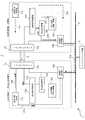
図4は、本発明の第2の実施形態に係る二重化制御システムのトラッキングバス異常時の動作を示す概略構成図である。第2の実施形態が第1の実施形態と異なる点は、監視操作装置6をさらに備える点である。監視操作装置6は、制御用伝送路4を介してA系制御装置2a、B系制御装置2bからトラッキング信号21a、21bを受信することができるように制御用伝送路4に接続される。 FIG. 4 is a schematic configuration diagram showing the operation when the tracking bus is abnormal in the redundant control system according to the second embodiment of the present invention. The second embodiment is different from the first embodiment in that a monitoring operation device 6 is further provided. The monitoring operation device 6 is connected to the control transmission line 4 so that the tracking signals 21a and 21b can be received from the
(作用)
以下、本発明の第2の実施形態の作用について説明する。以下、B系制御装置2bからA系制御装置2aに監視操作装置6を介してトラッキング信号21bを送信する場合を代表して説明する。A系制御装置2aは、上述したトラッキング異常を判定すると、制御用伝送路4を介して監視操作装置6にトラッキング信号21bを送信する。監視操作装置6は、トラッキング信号21bを受信し、さらに所定のタイミングでA系制御装置2aに送信する。(Function)
The operation of the second embodiment of the present invention will be described below. Hereinafter, a case where the
さらに監視操作装置6に制御用伝送路4の負荷を監視させ、制御用伝送路4の低負荷時においてトラッキング信号21bを送信させること、または複数回トラッキング信号21bを送信させることもできる。この場合、一時的な制御用伝送路4の高負荷状態やパケット喪失によって、B系制御装置2bからA系制御装置2aにトラッキング信号21bを送信することができなかった場合にも、監視操作装置6からトラッキング信号21bを取得することができる。 Further, it is possible to cause the monitoring operation device 6 to monitor the load of the control transmission line 4 and to transmit the
(効果)
本発明の第2の実施形態によれば、トラッキングバス3および制御用伝送路4による制御装置2間のトラッキングに加えて、監視操作装置6を介してトラッキングを行うことによって、より確実に各制御装置2のトラッキングバス3および他系の制御装置2の状態確認を行うことができる。(effect)
According to the second embodiment of the present invention, in addition to tracking between the
(第3の実施形態)
(構成)
以下、本発明の第3の実施形態に係る二重化制御システムについて図5を参照して説明する。第1の実施形態に係る二重化制御システムの各部と同一部分には同一符号を付し、同一の構成についての説明は省略する。(Third embodiment)
(Constitution)
The duplex control system according to the third embodiment of the present invention will be described below with reference to FIG. The same parts as those of the redundant control system according to the first embodiment are denoted by the same reference numerals, and the description of the same configuration is omitted.
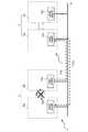
図5は、本発明の第3の実施形態に係る二重化制御システムのトラッキングバス異常時の動作を示す概略構成図である。第3の実施形態が第1の実施形態と異なる点は、二重化制御システム1が複数設けられる点である。複数の二重化制御システム1の各々の制御用伝送路IF16a、16bは、制御用伝送路4に接続される。 FIG. 5 is a schematic configuration diagram showing the operation when the tracking bus is abnormal in the redundant control system according to the third embodiment of the present invention. The third embodiment is different from the first embodiment in that a plurality of duplex control systems 1 are provided. The control transmission lines IF 16 a and 16 b of each of the plurality of duplex control systems 1 are connected to the control transmission line 4.
(作用)
以下、本発明の第3の実施形態の作用について説明する。複数のうち1つの二重化制御システム1においてトラッキング異常が発生した場合、この二重化制御システム1内の制御用伝送路IF16bは、他の二重化制御システム1の制御用伝送路IF16bへトラッキング信号21bを送信する。このとき、他の二重化制御システム1は、トラッキング信号21bの送信元の二重化制御システム1のトラッキング異常を判定し、送信元の二重化制御システム1の制御用伝送路IF16aにトラッキング信号21bを送信する。さらに他の二重化制御システム1は、受信したトラッキング信号21を保持し、制御用伝送路4の低負荷時においてトラッキング信号21を送信することもできる。(Function)
The operation of the third embodiment of the present invention will be described below. When a tracking abnormality occurs in one of the plurality of redundant control systems 1, the control transmission line IF 16b in the redundant control system 1 transmits a
(効果)
本発明の第3の実施形態によれば、1つの二重化制御システム1内でのトラッキングに加え、複数の二重化制御システム1間でトラッキングを行うことによって、より確実に各制御装置2がトラッキングバス3ならびに他系の制御装置2の状態確認を行うことができる。(effect)
According to the third embodiment of the present invention, in addition to tracking within one duplex control system 1, by performing tracking between a plurality of duplex control systems 1, each
(第4の実施形態)
(構成)
以下、本発明の第4の実施形態に係る二重化制御システムについて図6を参照して説明する。第1の実施形態に係る二重化制御システムの各部と同一部分には同一符号を付し、同一の構成についての説明は省略する。(Fourth embodiment)
(Constitution)
A duplex control system according to the fourth embodiment of the present invention will be described below with reference to FIG. The same parts as those of the redundant control system according to the first embodiment are denoted by the same reference numerals, and the description of the same configuration is omitted.
図6は、本発明の第4の実施形態に係る二重化制御システムのトラッキングバス異常時の動作を示す概略構成図である。である。第4の実施形態が第1の実施形態と異なる点は、制御装置2は、制御用伝送路4に代えて、インプット/アウトプット(IO)ネットワーク7と、入出力制御装置8をさらに備える点である。制御用伝送路IF16a、16bはそれぞれIOネットワーク7に接続される。また、入出力制御装置8はIOネットワーク7に接続される。IOネットワーク7は、主に制御装置2の演算結果や、制御装置2からプラント機器への指令の伝送路となるネットワークである。 FIG. 6 is a schematic configuration diagram showing the operation when the tracking bus is abnormal in the redundant control system according to the fourth embodiment of the present invention. It is. The fourth embodiment is different from the first embodiment in that the
(作用)
以下、本発明の第4の実施形態の作用について説明する。二重化制御システム1は、トラッキング異常が発生したとき、IOネットワーク7を介してトラッキング信号21a、21bを送信する。さらに、トラッキング信号21a、21bを入出力制御装置8に送信し、所定のタイミングで入出力制御装置8からトラッキング信号21a、21bを送信させることもできる。A系制御装置2a、B系制御装置2bはIOネットワーク7を介してトラッキング信号21a、21bを受信し、相手系の状態確認を行う。(Function)
The operation of the fourth embodiment of the present invention will be described below. The redundant control system 1 transmits
また、制御用伝送路IF16a、16bに制御用伝送路4およびIOネットワーク7を接続してもよい。この場合、制御用伝送路4またはIOネットワーク7を介してトラッキング信号21a、21bを送受信することができる。 Further, the control transmission line 4 and the IO network 7 may be connected to the control transmission lines IF 16a and 16b. In this case, the tracking signals 21 a and 21 b can be transmitted and received via the control transmission line 4 or the IO network 7.
(効果)
本発明の第4の実施形態によれば、制御系伝送路4に加えてIOネットワーク8を介してトラッキング信号21a、21bの交換をすることができ、より確実にA系制御装置2a、B系制御装置2bの状態確認を行うことができる。(effect)
According to the fourth embodiment of the present invention, the tracking signals 21a and 21b can be exchanged via the
なお、本発明の実施形態は上述した実施形態に限られないことは言うまでもない。例えば、各制御装置2の演算内容や制御内容は、二重化制御システム1が設けられるプラントの種類や二重化制御システム1の用途によって適宜変更されうるものである。また、上述した第1から第4の実施形態は適宜組み合わせることができる。 Needless to say, the embodiment of the present invention is not limited to the above-described embodiment. For example, the calculation content and control content of each
1・・・二重化制御システム
2・・・制御装置
2a・・・A系制御装置
2b・・・B系制御装置
3・・・トラッキングバス
4・・・伝送路
5・・・エンジニアリング装置
6・・・監視操作装置
7・・・インプットアウトプット(IO)ネットワーク
8・・・入出力制御装置
11a、b・・・自系状態判定部
12a、b・・・トラッキングバスインターフェイス(IF)
13a、b・・・他系信号確認部
14a、b・・・伝送路切替部
15a、b・・・系切替部
16a、b・・・制御用伝送路インターフェイス(IF)
21a、b・・・トラッキング信号
22a、b・・・伝送指令
23a、b・・・伝送路切替指令
31a、b・・・系切替信号DESCRIPTION OF SYMBOLS 1 ...
13a, b ... Other system
21a, b ...
Claims (5)
Translated fromJapanese2つの前記制御装置を接続し、2つの前記制御装置間でトラッキング信号を送受信させることができるトラッキングバスと、
2つの前記制御装置に接続され、2つの前記制御装置の演算情報を伝送する制御用伝送路と
前記制御用伝送路に設けられ、前記トラッキング信号を受信し保持することができる監視操作装置とを備え、
2つの前記制御装置は、
自系の状態判定を行い、この状態判定結果をトラッキング信号として前記トラッキングバスを介して他系の前記制御装置に送信する自系状態判定部と、
他系の前記制御装置から前記トラッキングバスを介して前記トラッキング信号を受信し、他系の前記制御装置の状態確認を行う他系信号確認部と、
この他系信号確認部において前記トラッキングバスを介して前記トラッキング信号を受信できない場合に、前記自系状態判定部に前記トラッキング信号を前記制御用伝送路を介して他系の前記他系信号確認部に送信させる伝送路切替部とを各々有し、
前記他系信号確認部において前記トラッキングバスを介して前記トラッキング信号を受信できない場合に、前記自系状態判定部は、前記制御用伝送路を介して前記トラッキング信号を監視操作装置に送信し、前記他系信号確認部は、前記監視操作装置から前記トラッキング信号を受信することを特徴とする二重化制御システム。Two control devices that operate with one set as a standby system and the other set as a regular system;
A tracking bus capable of connecting two control devices and transmitting and receiving a tracking signal between the two control devices;
A control transmission line that is connected to the two control devices and transmits computation information of the two control devices;
A monitoring operation device provided in the control transmission line and capable of receiving and holding the tracking signal ;
The two control devices are:
A self-system state determination unit that performs self-system state determination and transmits the state determination result as a tracking signal to the control device of another system via the tracking bus;
An other-system signal confirmation unit that receives the tracking signal from the other-system control device via the tracking bus and confirms the state of the other-system control device;
When the other system signal confirming unit cannot receive the tracking signal via the tracking bus, the other system signal confirming unit of the other system is transmitted to the own system state determining unit via the control transmission line. eachhave a transmission path switching unit for transmittingto,
When the other system signal confirmation unit cannot receive the tracking signal via the tracking bus, the own system state determination unit transmits the tracking signal to the monitoring operation device via the control transmission line, The duplex control system, wherein the other system signal confirmation unit receives thetracking signal from the monitoring operation device .
2つの前記制御装置を接続し、2つの前記制御装置間でトラッキング信号を送受信させることができるトラッキングバスと、
2つの前記制御装置に接続され、2つの前記制御装置の演算情報を伝送する制御用伝送路とを備え、
2つの前記制御装置は、
自系の状態判定を行い、この状態判定結果をトラッキング信号として前記トラッキングバスを介して他系の前記制御装置に送信する自系状態判定部と、
他系の前記制御装置から前記トラッキングバスを介して前記トラッキング信号を受信し、
他系の前記制御装置の状態確認を行う他系信号確認部と、
この他系信号確認部において前記トラッキングバスを介して前記トラッキング信号を受信できない場合に、前記自系状態判定部に前記トラッキング信号を前記制御用伝送路を介して他系の前記他系信号確認部に送信させる伝送路切替部とを各々有する
二重化制御システムを複数備え、
前記他系信号確認部において前記トラッキングバスを介して前記トラッキング信号を受信
できない場合に、複数のうち1つの前記二重化制御システムから他の前記二重化制御シス
テムにトラッキング信号を送信し、受信することができることを特徴とする二重化制御システム。Two control devices that operate with one set as a standby system and the other set as a regular system;
A tracking bus capable of connecting two control devices and transmitting and receiving a tracking signal between the two control devices;
A control transmission line that is connected to the two control devices and transmits computation information of the two control devices;
The two control devices are:
A self-system state determination unit that performs self-system state determination and transmits the state determination result as a tracking signal to the control device of another system via the tracking bus;
Receiving the tracking signal from the control device of another system via the tracking bus;
Another system signal confirmation unit for confirming the state of the control device of another system;
When the other system signal confirming unit cannot receive the tracking signal via the tracking bus, the other system signal confirming unit of the other system is transmitted to the own system state determining unit via the control transmission line. Each having a transmission line switching unit
Equipped with multiple redundant control systems,
The other system signal confirmation unit receives the tracking signal via the tracking bus.
If it is not possible, one of the redundant control systems out of a plurality of the redundant control systems
A duplex control systemcapable of transmitting and receiving a tracking signal to a system.
をさらに備え、
前記他系信号確認部において前記トラッキングバスを介して前記トラッキング信号を受信
できない場合に、前記インプットアウトプットネットワークを介して他系の前記他系信号
確認部に前記トラッキング信号を送信することを特徴とする請求項1乃至請求項4の何れ
か一項に記載の二重化制御システム。An input / output network capable of transmitting the calculation result of the control device;
When the other system signal confirmation unit cannot receive the tracking signal via the tracking bus, the tracking signal is transmitted to the other system signal confirmation unit of the other system via the input output network. The duplex control system according to any one of claims 1 to4 .
Priority Applications (5)
| Application Number | Priority Date | Filing Date | Title |
|---|---|---|---|
| JP2012013377AJP5706347B2 (en) | 2012-01-25 | 2012-01-25 | Redundant control system |
| PCT/JP2012/008147WO2013111240A1 (en) | 2012-01-25 | 2012-12-20 | Duplex control system and control method therefor |
| CN201280067962.8ACN104067235A (en) | 2012-01-25 | 2012-12-20 | Dual control system and its control method |
| DE112012005740.6TDE112012005740T5 (en) | 2012-01-25 | 2012-12-20 | Duplex control system and its control method |
| US14/341,112US9910754B2 (en) | 2012-01-25 | 2014-07-25 | Duplexed control system and control method thereof |
Applications Claiming Priority (1)
| Application Number | Priority Date | Filing Date | Title |
|---|---|---|---|
| JP2012013377AJP5706347B2 (en) | 2012-01-25 | 2012-01-25 | Redundant control system |
Publications (2)
| Publication Number | Publication Date |
|---|---|
| JP2013152631A JP2013152631A (en) | 2013-08-08 |
| JP5706347B2true JP5706347B2 (en) | 2015-04-22 |
Family
ID=48873018
Family Applications (1)
| Application Number | Title | Priority Date | Filing Date |
|---|---|---|---|
| JP2012013377AActiveJP5706347B2 (en) | 2012-01-25 | 2012-01-25 | Redundant control system |
Country Status (5)
| Country | Link |
|---|---|
| US (1) | US9910754B2 (en) |
| JP (1) | JP5706347B2 (en) |
| CN (1) | CN104067235A (en) |
| DE (1) | DE112012005740T5 (en) |
| WO (1) | WO2013111240A1 (en) |
Families Citing this family (5)
| Publication number | Priority date | Publication date | Assignee | Title |
|---|---|---|---|---|
| US9934114B2 (en) | 2013-09-26 | 2018-04-03 | Mistubishi Electric Corporation | Communication system, standby device, communication method, and standby program |
| JP6234388B2 (en)* | 2015-01-21 | 2017-11-22 | 三菱電機株式会社 | Dual system controller |
| KR101815202B1 (en) | 2015-02-12 | 2018-01-05 | 후지 덴키 가부시키가이샤 | Control system and relay apparatus |
| US11016449B2 (en)* | 2015-07-23 | 2021-05-25 | Mitsubishi Electric Corporation | Duplexing process control device |
| JP7326239B2 (en)* | 2020-09-16 | 2023-08-15 | 株式会社東芝 | Controller and controller system |
Family Cites Families (16)
| Publication number | Priority date | Publication date | Assignee | Title |
|---|---|---|---|---|
| JPH01261739A (en)* | 1988-04-13 | 1989-10-18 | Nec Corp | Confirming system for processor normality in distributed processing system |
| JPH07200502A (en)* | 1993-12-28 | 1995-08-04 | Omron Corp | Dual system for transaction processing system |
| JPH07230301A (en) | 1994-02-17 | 1995-08-29 | Yokogawa Electric Corp | Distributed controller |
| JPH10222388A (en)* | 1997-02-04 | 1998-08-21 | Hitachi Ltd | Hot standby method for parallel computers |
| US6477139B1 (en)* | 1998-11-15 | 2002-11-05 | Hewlett-Packard Company | Peer controller management in a dual controller fibre channel storage enclosure |
| JP2001356927A (en) | 2000-06-14 | 2001-12-26 | Mitsubishi Electric Corp | Duplex system |
| FI115015B (en)* | 2002-04-22 | 2005-02-15 | Metso Automation Oy | Procedure and system for securing a bus and control server |
| US6868067B2 (en)* | 2002-06-28 | 2005-03-15 | Harris Corporation | Hybrid agent-oriented object model to provide software fault tolerance between distributed processor nodes |
| US7511614B2 (en)* | 2003-02-03 | 2009-03-31 | Ingrid, Inc. | Portable telephone in a security network |
| JP2006172050A (en)* | 2004-12-15 | 2006-06-29 | Yaskawa Information Systems Co Ltd | Hot standby dual system |
| JP2007304687A (en)* | 2006-05-09 | 2007-11-22 | Hitachi Ltd | Cluster configuration and control method |
| JP2009080704A (en)* | 2007-09-26 | 2009-04-16 | Toshiba Corp | Virtual computer system and service takeover control method in the same system |
| JP2009205364A (en)* | 2008-02-27 | 2009-09-10 | Nec Corp | Life-and-death monitoring method, monitored device, monitor and life-and-death monitoring program |
| JP2011123808A (en)* | 2009-12-14 | 2011-06-23 | Toshiba Corp | Plant control system and failure occurrence determination method for the same |
| JP2011203941A (en)* | 2010-03-25 | 2011-10-13 | Nec Corp | Information processing apparatus, monitoring method and monitoring program |
| JP5304700B2 (en)* | 2010-03-25 | 2013-10-02 | ブラザー工業株式会社 | Status notification method and communication system |
- 2012
- 2012-01-25JPJP2012013377Apatent/JP5706347B2/enactiveActive
- 2012-12-20WOPCT/JP2012/008147patent/WO2013111240A1/ennot_activeCeased
- 2012-12-20DEDE112012005740.6Tpatent/DE112012005740T5/ennot_activeWithdrawn
- 2012-12-20CNCN201280067962.8Apatent/CN104067235A/enactivePending
- 2014
- 2014-07-25USUS14/341,112patent/US9910754B2/enactiveActive
Also Published As
| Publication number | Publication date |
|---|---|
| US20140336794A1 (en) | 2014-11-13 |
| US9910754B2 (en) | 2018-03-06 |
| DE112012005740T5 (en) | 2014-10-09 |
| WO2013111240A1 (en) | 2013-08-01 |
| JP2013152631A (en) | 2013-08-08 |
| CN104067235A (en) | 2014-09-24 |
Similar Documents
| Publication | Publication Date | Title |
|---|---|---|
| JP4776374B2 (en) | Redundant supervisory control system and redundant switching method for the same system | |
| JP4782823B2 (en) | User terminal, master unit, communication system and operation method thereof | |
| CN103955188B (en) | Control system and method supporting redundancy switching function | |
| CN102611598B (en) | Bus redundancy system of controller local area network and method and device for switching redundancy | |
| JP5706347B2 (en) | Redundant control system | |
| JP5554292B2 (en) | Redundant controller | |
| KR100823722B1 (en) | Triplexing apparatus and method of PLC system | |
| US10386832B2 (en) | Redundant control system for an actuator and method for redundant control thereof | |
| JP2008544678A (en) | Communication network system | |
| JP5281566B2 (en) | Railway security system | |
| CN102402212B (en) | For method and the network of operational network | |
| US20130019040A1 (en) | Field communication system | |
| KR101846222B1 (en) | Redundancy system and controllin method thereof | |
| JP5459117B2 (en) | Data transmission apparatus and data transmission method | |
| JP7035511B2 (en) | Programmable controller and duplex system | |
| JP2014071773A (en) | Duplex control device and control method of the same | |
| JP6234388B2 (en) | Dual system controller | |
| JPWO2006075403A1 (en) | Transmission apparatus and failure notification method | |
| JP2014164472A (en) | Information processing system and failure management method of information processing device | |
| JP2013254333A (en) | Multiple system control system and control method therefor | |
| JP6194560B2 (en) | Node device and communication method | |
| JP3279068B2 (en) | Redundant controller | |
| JP2007018026A (en) | controller | |
| JP5602071B2 (en) | CPU duplex control system | |
| KR20150068874A (en) | Apparatus and method for field bus controller redundancy |
Legal Events
| Date | Code | Title | Description |
|---|---|---|---|
| A621 | Written request for application examination | Free format text:JAPANESE INTERMEDIATE CODE: A621 Effective date:20140114 | |
| A131 | Notification of reasons for refusal | Free format text:JAPANESE INTERMEDIATE CODE: A131 Effective date:20141107 | |
| A521 | Request for written amendment filed | Free format text:JAPANESE INTERMEDIATE CODE: A523 Effective date:20141226 | |
| TRDD | Decision of grant or rejection written | ||
| A01 | Written decision to grant a patent or to grant a registration (utility model) | Free format text:JAPANESE INTERMEDIATE CODE: A01 Effective date:20150130 | |
| A61 | First payment of annual fees (during grant procedure) | Free format text:JAPANESE INTERMEDIATE CODE: A61 Effective date:20150226 | |
| R150 | Certificate of patent or registration of utility model | Ref document number:5706347 Country of ref document:JP Free format text:JAPANESE INTERMEDIATE CODE: R150 | |
| S111 | Request for change of ownership or part of ownership | Free format text:JAPANESE INTERMEDIATE CODE: R313115 | |
| R350 | Written notification of registration of transfer | Free format text:JAPANESE INTERMEDIATE CODE: R350 | |
| S531 | Written request for registration of change of domicile | Free format text:JAPANESE INTERMEDIATE CODE: R313531 | |
| R360 | Written notification for declining of transfer of rights | Free format text:JAPANESE INTERMEDIATE CODE: R360 | |
| R360 | Written notification for declining of transfer of rights | Free format text:JAPANESE INTERMEDIATE CODE: R360 | |
| R371 | Transfer withdrawn | Free format text:JAPANESE INTERMEDIATE CODE: R371 |