JP5705040B2 - Manufacturing method of cover glass for portable device - Google Patents
Manufacturing method of cover glass for portable deviceDownload PDFInfo
- Publication number
- JP5705040B2 JP5705040B2JP2011135723AJP2011135723AJP5705040B2JP 5705040 B2JP5705040 B2JP 5705040B2JP 2011135723 AJP2011135723 AJP 2011135723AJP 2011135723 AJP2011135723 AJP 2011135723AJP 5705040 B2JP5705040 B2JP 5705040B2
- Authority
- JP
- Japan
- Prior art keywords
- glass
- plate
- etching
- main surface
- exposed
- Prior art date
- Legal status (The legal status is an assumption and is not a legal conclusion. Google has not performed a legal analysis and makes no representation as to the accuracy of the status listed.)
- Expired - Fee Related
Links
- 239000006059cover glassSubstances0.000titleclaimsdescription31
- 238000004519manufacturing processMethods0.000titleclaimsdescription31
- 239000011521glassSubstances0.000claimsdescription79
- 239000005357flat glassSubstances0.000claimsdescription73
- 238000000034methodMethods0.000claimsdescription51
- 238000005530etchingMethods0.000claimsdescription48
- 239000000463materialSubstances0.000claimsdescription37
- 239000000758substrateSubstances0.000claimsdescription37
- 230000008569processEffects0.000claimsdescription36
- 238000000576coating methodMethods0.000claimsdescription13
- 238000005520cutting processMethods0.000claimsdescription7
- 239000011248coating agentSubstances0.000claimsdescription6
- 238000000227grindingMethods0.000claimsdescription3
- 229920002120photoresistant polymerPolymers0.000claimsdescription3
- 238000004090dissolutionMethods0.000claims2
- KRHYYFGTRYWZRS-UHFFFAOYSA-NFluoraneChemical compoundFKRHYYFGTRYWZRS-UHFFFAOYSA-N0.000description10
- 238000001035dryingMethods0.000description5
- 238000001039wet etchingMethods0.000description5
- 238000003426chemical strengthening reactionMethods0.000description4
- 238000001312dry etchingMethods0.000description4
- 238000005342ion exchangeMethods0.000description4
- 230000001681protective effectEffects0.000description4
- HEMHJVSKTPXQMS-UHFFFAOYSA-MSodium hydroxideChemical compound[OH-].[Na+]HEMHJVSKTPXQMS-UHFFFAOYSA-M0.000description3
- 238000000605extractionMethods0.000description3
- 238000003754machiningMethods0.000description3
- 239000006060molten glassSubstances0.000description3
- 239000000243solutionSubstances0.000description3
- 229910018072Al 2 O 3Inorganic materials0.000description2
- YCKRFDGAMUMZLT-UHFFFAOYSA-NFluorine atomChemical compound[F]YCKRFDGAMUMZLT-UHFFFAOYSA-N0.000description2
- VEXZGXHMUGYJMC-UHFFFAOYSA-NHydrochloric acidChemical compoundClVEXZGXHMUGYJMC-UHFFFAOYSA-N0.000description2
- 229910018068Li 2 OInorganic materials0.000description2
- QAOWNCQODCNURD-UHFFFAOYSA-NSulfuric acidChemical compoundOS(O)(=O)=OQAOWNCQODCNURD-UHFFFAOYSA-N0.000description2
- 239000005354aluminosilicate glassSubstances0.000description2
- 238000004140cleaningMethods0.000description2
- 229910052731fluorineInorganic materials0.000description2
- 239000011737fluorineSubstances0.000description2
- 239000011347resinSubstances0.000description2
- 229920005989resinPolymers0.000description2
- GRYLNZFGIOXLOG-UHFFFAOYSA-NNitric acidChemical compoundO[N+]([O-])=OGRYLNZFGIOXLOG-UHFFFAOYSA-N0.000description1
- 238000006124Pilkington processMethods0.000description1
- 229910004298SiO 2Inorganic materials0.000description1
- 239000002253acidSubstances0.000description1
- 239000003929acidic solutionSubstances0.000description1
- NIXOWILDQLNWCW-UHFFFAOYSA-Nacrylic acid groupChemical groupC(C=C)(=O)ONIXOWILDQLNWCW-UHFFFAOYSA-N0.000description1
- 239000012670alkaline solutionSubstances0.000description1
- 239000007864aqueous solutionSubstances0.000description1
- 230000008901benefitEffects0.000description1
- 230000015572biosynthetic processEffects0.000description1
- 239000005388borosilicate glassSubstances0.000description1
- 230000008859changeEffects0.000description1
- 238000010586diagramMethods0.000description1
- 238000003280down draw processMethods0.000description1
- 150000002500ionsChemical class0.000description1
- 230000001678irradiating effectEffects0.000description1
- 239000004973liquid crystal related substanceSubstances0.000description1
- 238000012986modificationMethods0.000description1
- 230000004048modificationEffects0.000description1
- 229910017604nitric acidInorganic materials0.000description1
- 230000002093peripheral effectEffects0.000description1
- 230000009467reductionEffects0.000description1
- 239000005361soda-lime glassSubstances0.000description1
- 229910001415sodium ionInorganic materials0.000description1
Images


Landscapes
- Liquid Crystal (AREA)
- Re-Forming, After-Treatment, Cutting And Transporting Of Glass Products (AREA)
- Surface Treatment Of Glass (AREA)
Description
Translated fromJapanese本発明は、携帯電話やスマートフォン、PDA(Personal Digital Assistant)などの携帯機器の表示画面の保護に用いられる携帯機器用カバーガラスの製造方法に関する。 The present invention relates to a method for manufacturing a cover glass for a mobile device used for protecting a display screen of a mobile device such as a mobile phone, a smartphone, or a PDA (Personal Digital Assistant).
携帯電話やスマートフォン、PDAなどの携帯機器においては、液晶などの表示装置を保護するために、表示装置の外側に透明な保護板が配置される。保護板としてはアクリルなどの樹脂が多く用いられているが、樹脂の保護板はたわみやすいため、板厚を厚くしたり、表示装置との間隙を多く取ったりする必要がある。 In portable devices such as a mobile phone, a smartphone, and a PDA, a transparent protective plate is disposed outside the display device in order to protect the display device such as a liquid crystal. A resin such as acrylic is often used as the protective plate. However, since the protective plate made of resin is easily bent, it is necessary to increase the thickness of the plate or to leave a large gap with the display device.
そこで、上記の表示装置の保護板として、ガラス素材からなるカバーガラスが普及し始めている。ガラスは硬度が高いためにたわみが少なく、薄型化に寄与することができる。一般に、カバーガラスは、板状ガラスからカバーガラスの形状のガラス基板を複数枚抜き出し製造される。 Therefore, cover glasses made of a glass material have begun to spread as protective plates for the above display devices. Since glass has high hardness, there is little deflection and it can contribute to thickness reduction. Generally, a cover glass is manufactured by extracting a plurality of glass substrates in the shape of a cover glass from a plate glass.
板状ガラスからガラス基板を抜き出す方法としては、従来では機械加工が主流であったが、近年では特許文献1のようにエッチングを用いた方法が開発されている。特許文献1では、マスクとなるレジストパターンを主表面に形成した板状ガラスをエッチャントでエッチングすることにより、かかる板状ガラスからカバーガラスの形状のガラス基板を抜き出している。このようにエッチングで外形を形成することにより、端面は非常に高い平滑性を有し、機械加工で生じるマイクロクラックが生じない。このため、携帯機器用カバーガラスに求められる高い強度を得ることができる。また、機械加工では困難な複雑な形状であっても、エッチングであれば容易に加工することができるという利点もある。 As a method for extracting a glass substrate from a sheet glass, conventionally, machining has been the mainstream, but recently, a method using etching as in Patent Document 1 has been developed. In patent document 1, the glass substrate of the shape of a cover glass is extracted from this plate-shaped glass by etching the plate-shaped glass in which the resist pattern used as a mask was formed in the main surface with an etchant. By forming the outer shape by etching in this way, the end surface has very high smoothness, and microcracks caused by machining do not occur. For this reason, the high intensity | strength calculated | required by the cover glass for portable devices can be obtained. Further, there is an advantage that even a complicated shape difficult to machine can be easily processed by etching.
エッチングによるガラス基板の抜き出しでは、上述したように板状ガラスの主表面にレジストパターンを形成する。このレジストパターンの形成では、まず板状ガラスの主表面にレジスト材をコーティングする。次に、所望のマスクパターンを有するフォトマスクを、レジスト材がコーティングされた板状ガラスの両主表面と平行に配置して板状ガラスの両面から露光し、露光後の板状ガラスを現像液に浸漬して現像することによりレジストパターンが形成される。 In extracting the glass substrate by etching, a resist pattern is formed on the main surface of the plate-like glass as described above. In the formation of the resist pattern, first, a resist material is coated on the main surface of the sheet glass. Next, a photomask having a desired mask pattern is arranged in parallel with both main surfaces of the sheet glass coated with a resist material, and exposed from both sides of the sheet glass, and the exposed sheet glass is developed as a developer. A resist pattern is formed by developing the film by immersing it in the film.
このとき、フォトマスクを、抜き出したい領域すなわち複数のガラス基板に対応する領域を露光し、且つその露光される領域以外を遮光するマスクパターンとする(以下、板状ガラスにおいて、露光される領域を露光領域、遮光される領域を遮光領域と称する)。すると、露光時には、板状ガラスにおいて、露光領域にのみ光が照射されてレジスト材が変質し、現像液に溶解しないようになる。フォトマスクによって覆われて光が照射されなかった遮光領域にコーティングされていたレジスト材は、現像時に現像液に溶解する。これにより、板状ガラスに、ガラス基板に対応する領域(露光領域)にのみマスク(レジスト)を有するレジストパターンが形成される。 At this time, the photomask is used as a mask pattern that exposes an area to be extracted, that is, an area corresponding to a plurality of glass substrates, and shields light other than the exposed area (hereinafter, the exposed area in the plate glass is referred to as an exposed area). The exposure area and the light-shielded area are referred to as a light-shielded area). Then, at the time of exposure, in the sheet glass, light is irradiated only to the exposure region, the resist material is denatured, and is not dissolved in the developer. The resist material coated on the light-shielding region that is covered with the photomask and not irradiated with light is dissolved in the developer during development. Thereby, the resist pattern which has a mask (resist) only in the area | region (exposure area | region) corresponding to a glass substrate in plate-shaped glass is formed.
そして、レジストパターン形成後の板状ガラスをエッチングすると、板状ガラスにおいて、レジストパターンによってマスキングされている露光領域はエッチャントから保護され、レジストが形成されていない遮光領域はエッチャントによりエッチングされる。これにより、複数のガラス基板に対応する露光領域が分離し、複数のカバーガラスの形状のガラス基板が抜き出される。 When the plate-like glass after the resist pattern is formed is etched, the exposed region masked by the resist pattern is protected from the etchant in the plate-like glass, and the light-shielding region where the resist is not formed is etched by the etchant. Thereby, the exposure area | region corresponding to several glass substrate isolate | separates, and the glass substrate of the shape of several cover glass is extracted.
上記ガラス基板の抜き出しは、製造効率および製品品質を向上させるため、板状ガラスを両面からエッチングする。このため、板状ガラスの両面にレジストパターンを形成して両面同時に露光する必要がある。故に、露光工程では板状ガラスを把持する必要がある。 Extraction of the glass substrate etches the glass sheet from both sides in order to improve production efficiency and product quality. For this reason, it is necessary to form a resist pattern on both surfaces of the plate glass and expose both surfaces simultaneously. Therefore, it is necessary to hold the glass sheet in the exposure process.
ここで、従来のエッチング方法では、板状ガラスにおいて遮光領域以外の領域もエッチャントによりエッチングされる。詳細には、板状ガラスの露光では、その両主表面に各々対向する位置に配置された照射装置の間にかかる板状ガラスが配置され、周囲の縁部を把持された状態で露光される。このため、板状ガラスにおいて把持されている縁部には光は照射されない(以下、この照射を受けない縁部を非露光領域と称する)。したがって、その非露光領域にコーティングされたレジスト材は、現像時に、遮光領域にコーティングされていたレジスト材とともに現像液に溶解する。その結果、板状ガラスの非露光領域は、エッチング工程時に、遮光領域と同様にエッチャントにエッチングされる。 Here, in the conventional etching method, regions other than the light shielding region in the plate glass are also etched by the etchant. Specifically, in the exposure of the sheet glass, the sheet glass is disposed between the irradiation devices disposed at positions opposed to both the main surfaces, and the exposure is performed with the peripheral edge held. . For this reason, light is not irradiated to the edge part hold | maintained in plate-like glass (henceforth, the edge part which does not receive this irradiation is called a non-exposure area | region). Therefore, the resist material coated on the non-exposed area is dissolved in the developer together with the resist material coated on the light shielding area at the time of development. As a result, the non-exposed area of the glass sheet is etched into the etchant in the same manner as the light shielding area during the etching process.
上述したように、板状ガラスのエッチングにおいて、遮光領域のエッチングは、露光領域を分離してガラス基板を抜き出すために必須であるものの、非露光領域はガラス基板の抜き出しに関与しない領域であるため、かかる非露光領域はエッチングする必要はない。むしろ、非露光領域までもがエッチングしてしまうと、エッチャントの寿命が短くなるためエッチャントを無駄に消費することとなり、その消費量ひいては製造コストの増大を招いてしまう。 As described above, in the etching of the glass sheet, the etching of the light shielding region is indispensable for separating the exposed region and extracting the glass substrate, but the non-exposed region is a region not involved in the extraction of the glass substrate. Such non-exposed areas need not be etched. Rather, if even the non-exposed area is etched, the lifetime of the etchant is shortened, so that the etchant is wasted, and the consumption amount and thus the manufacturing cost is increased.
また、板状ガラスにレジスト材をコーティングする際、一方の片面をコーティングしてその面を乾燥した後に、他方の片面をコーティングしてその面を乾燥するよりも、両面を同時にコーティングし、その両面を同時に乾燥する方が製造効率および製品品質が向上する。そこで、レジスト材を両面同時にコーティングする場合には、板状ガラスを把持する必要がある。 In addition, when coating a resist material on a plate glass, both sides are coated at the same time, rather than coating one side and drying that side, then coating the other side and drying that side. Manufacturing efficiency and product quality are improved by drying at the same time. Therefore, when the resist material is coated on both sides simultaneously, it is necessary to grip the plate glass.
上記のように両面同時にコーティングする際、板状ガラスにはレジスト材を塗れない部分が生じる。このため、やはり板状ガラスの縁部に板状ガラスの主表面が露出している部分が形成される。この場合にも同様に、エッチャントの消費量および製造コストの増大を招くという問題がある。 When both surfaces are coated simultaneously as described above, a portion where the resist material cannot be applied to the plate glass is generated. Therefore, a portion where the main surface of the plate glass is exposed is formed at the edge of the plate glass. In this case as well, there is a problem that the consumption of the etchant and the manufacturing cost are increased.
本発明は、このような課題に鑑み、エッチング工程時に板状ガラスの縁部の主表面が露出した部分のエッチングを防ぎ、エッチャントの消費量ひいては製造コストの削減を図ることが可能な携帯機器用カバーガラスの製造方法を提供することを目的としている。 In view of such a problem, the present invention prevents the etching of the exposed portion of the main surface of the edge of the sheet glass during the etching process, and can reduce the consumption of the etchant and thus the manufacturing cost. It aims at providing the manufacturing method of a cover glass.
上記課題を解決するために、本発明の代表的な構成は、板状ガラスから、携帯機器用カバーガラス形状のガラス基板をエッチングにより抜き出すエッチング工程を含む、携帯機器用カバーガラスの製造方法であって、板状ガラスの両主表面上に形成されているネガ型のレジスト材に対してガラス基板に対応する領域を露光するマスクパターンを有するフォトマスクを用いて、板状ガラスの主表面の縁部を把持した状態で板状ガラスの両主表面側から露光する露光工程と、露光工程後の板状ガラスを現像してレジストパターンを形成する現像工程と、現像工程によって板状ガラスの主表面が露出した縁部を除去する除去工程と、現像工程によって、板状ガラスの主表面が露出した領域をエッチングすることにより板状ガラスからガラス基板を抜き出すエッチング工程と、を含むことを特徴する。 In order to solve the above-described problems, a typical configuration of the present invention is a method for manufacturing a cover glass for a portable device, which includes an etching step of extracting a glass substrate in the shape of a cover glass for a portable device from a sheet glass by etching. The edge of the main surface of the plate glass using a photomask having a mask pattern that exposes a region corresponding to the glass substrate with respect to the negative resist material formed on both main surfaces of the plate glass An exposure process that exposes from both main surface sides of the sheet glass while holding the part, a development process that develops the sheet glass after the exposure process to form a resist pattern, and a main surface of the sheet glass by the development process The glass substrate is removed from the plate glass by etching the region where the main surface of the plate glass is exposed by the removal step of removing the exposed edge and the development step. To comprising an etching step of issuing, the.
上記構成によれば、エッチング工程前の除去工程において、板状ガラスの縁部に板状ガラスの主表面が露出している部分(非露光領域)が除去される。これにより、エッチング工程における非露光領域のエッチングが生じないため、エッチャントの消費量ひいては製造コストの削減を図ることが可能となる。 According to the said structure, in the removal process before an etching process, the part (non-exposed area | region) in which the main surface of plate glass is exposed to the edge of plate glass is removed. As a result, the etching of the non-exposed region does not occur in the etching process, so that the consumption of the etchant and thus the manufacturing cost can be reduced.
本発明の他の代表的な構成は、板状ガラスから、携帯機器用カバーガラス形状のガラス基板をエッチングにより抜き出すエッチング工程を含む、携帯機器用カバーガラスの製造方法であって、板状ガラスの主表面の縁部を把持した状態で両主表面上にネガ型またはポジ型のレジスト材をコーティングするコーティング工程と、板状ガラスの両主表面上においてガラス基板に対応する領域を露光するマスクパターンを有するフォトマスクを用いて、板状ガラスの両主表面側からレジスト材を露光する露光工程と、露光工程後の板状ガラスを現像してレジストパターンを形成する現像工程と、板状ガラスの主表面が露出した縁部を除去する除去工程と、現像工程によって、板状ガラスの主表面が露出した領域をエッチングすることにより板状ガラスからガラス基板を抜き出すエッチング工程と、を含むことを特徴する。 Another representative configuration of the present invention is a method for producing a cover glass for a portable device, which includes an etching step of extracting a glass substrate in the shape of a cover glass for a portable device from the sheet glass by etching. A coating process that coats negative or positive resist material on both main surfaces while holding the edge of the main surface, and a mask pattern that exposes the area corresponding to the glass substrate on both main surfaces of the sheet glass An exposure step of exposing the resist material from both main surface sides of the plate glass, a development step of developing the plate glass after the exposure step to form a resist pattern, and a plate glass By removing the edge portion where the main surface is exposed and the developing step, the region where the main surface of the plate glass is exposed is etched to form a plate-like glass. To characterized in that it comprises, an etching step for extracting the glass substrate from.
上記のように、コーティング工程においてレジスト材を塗れない部分があった場合にも、やはり板状ガラスの縁部に板状ガラスの主表面が露出している部分が形成される。そして、これをエッチング工程前の除去工程において除去することにより、板状ガラスの主表面が露出している部分の溶解が生じないため、エッチャントの消費量ひいては製造コストの削減を図ることが可能となる。 As described above, even when there is a portion where the resist material cannot be applied in the coating process, a portion where the main surface of the plate glass is exposed at the edge of the plate glass is also formed. Then, by removing this in the removing step before the etching step, the portion where the main surface of the sheet glass is exposed does not melt, so that it is possible to reduce the consumption of the etchant and thus the manufacturing cost. Become.
本発明によれば、エッチング工程時に板状ガラスの縁部の主表面が露出した部分のエッチングを防ぎ、エッチャントの消費量ひいては製造コストの削減を図ることが可能な携帯機器用カバーガラスの製造方法を提供することができる。 According to the present invention, a method for manufacturing a cover glass for a portable device capable of preventing etching of a portion where the main surface of the edge portion of the glass sheet is exposed during the etching process, and reducing consumption of the etchant and thus manufacturing cost. Can be provided.
以下に添付図面を参照しながら、本発明の好適な実施形態について詳細に説明する。かかる実施形態に示す寸法、材料、その他具体的な数値などは、発明の理解を容易とするための例示に過ぎず、特に断る場合を除き、本発明を限定するものではない。なお、本明細書及び図面において、実質的に同一の機能、構成を有する要素については、同一の符号を付することにより重複説明を省略し、また本発明に直接関係のない要素は図示を省略する。 Hereinafter, preferred embodiments of the present invention will be described in detail with reference to the accompanying drawings. The dimensions, materials, and other specific numerical values shown in the embodiments are merely examples for facilitating understanding of the invention, and do not limit the present invention unless otherwise specified. In the present specification and drawings, elements having substantially the same function and configuration are denoted by the same reference numerals, and redundant description is omitted, and elements not directly related to the present invention are not illustrated. To do.
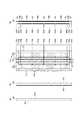
図1は、本実施形態にかかる携帯機器用カバーガラスの製造方法を説明する概略図である。図2および図3は、本実施形態にかかる製造方法を適用した板状ガラス102の断面図であり、図1の板状ガラス102の水平方向の断面が図示されている。 FIG. 1 is a schematic diagram for explaining a method for producing a cover glass for a portable device according to the present embodiment. 2 and 3 are sectional views of the
本実施形態にかかる携帯機器用カバーガラス(以下、単にカバーガラスと称する)の製造方法では、まず、図2(a)に示す板状ガラス102の主表面102aおよび102bに、後述するレジストパターン106(図3(a)参照)を形成し、エッチャントでエッチングすることによりカバーガラスの形状に抜き出して、不図示の携帯機器用のカバーガラスの形状のガラス基板100(図3(e)参照)を製造する。このようにして製造されたガラス基板100を用いたカバーガラスは、エッチングにより外形を形成しているので、端面はエッチング面となって非常に高い平滑性を有し、機械加工で生じるマイクロクラックが生じないため、携帯端末用カバーガラスに求められる高い強度を得ることができる。また、機械加工では困難な複雑な形状であっても、容易に加工することができる。 In the method for manufacturing a cover glass for a portable device (hereinafter simply referred to as a cover glass) according to the present embodiment, first, a resist
図1(a)は板状ガラス102の平面図である。本実施形態では、図1(a)において破線にて囲った領域を抜き出し、カバーガラスに用いられるガラス基板100を製造する。このように本実施形態では板状ガラス102から27個のガラス基板100を抜き出す場合を説明するが、この数は例示であり、これに限定するものではない。 FIG. 1A is a plan view of the
板状ガラス102は、溶融ガラスから直接シート状に成型したもの、あるいは、ある厚さに成型されたガラス体を所定の厚さに成型し、主表面を研磨して所定の厚さに仕上げたものを使用することができる。特に、溶融ガラスから直接シート状に成型した場合には、板状ガラス102の主表面102aおよび102b(以下、主表面102aおよび102bを総称するときは単に両主表面と称する。)がマイクロクラックのない表面状態を有するため好ましい。溶融ガラスから直接シート状に成型する方法としては、ダウンドロー法、フロート法などが挙げられる。 The
板状ガラス102は、アルミノシリケートガラス、ソーダライムガラス、ボロシリケートガラス、結晶化ガラスなどで構成されていることが好ましい。中でも、SiO2、Al2O3、Li2O及び/又はNa2Oを含有したアルミノシリケートガラスであることが好ましい。Al2O3は、後述する化学強化においてイオン交換性能を向上させるため有用である。Li2Oは、化学強化においてNaイオンとイオン交換させるための成分である。Na2Oは、化学強化においてKイオンとイオン交換させるための成分である。ZrO2は、機械的強度を高めるために有用である。The
上記の板状ガラス102へのレジストパターン形成では、まず図2(b)に示すように、板状ガラス102の両主表面上にレジスト材104をコーティングする(コーティング工程)。レジスト材104としては、エッチングする際に使用するエッチャントに対して耐性を有する材料であればよい。ガラスは大抵、フッ酸を含む水溶液のウェットエッチングや、フッ素系ガスのドライエッチングにより食刻されるので、例えば、フッ酸耐性に優れたレジスト材などを用いることができる。 In forming the resist pattern on the
次に、図2(c)に示すように、板状ガラス102の両主表面上において複数のガラス基板100に対応する領域を露光するマスクパターンを有するフォトマスク110を、コーティング工程後の板状ガラス102の両主表面と平行に配置する。そして、板状ガラス102の両主表面上に形成されているネガ型のレジスト材104に対して、板状ガラス102の主表面の縁部を把持した状態で、板状ガラス102の両主表面側からUVランプ等の照射装置112によって光(UV)を照射して露光する(露光工程)。 Next, as shown in FIG. 2C, a
図1(b)は板状ガラス102の各領域を説明する平面図である。図1(b)に示すように、本実施形態の板状ガラス102では、斜線にてハッチングされる領域(図1(a)にて破線にて囲った領域)が、複数のガラス基板100に対応する領域(抜き出したい領域)である。このため、かかる領域を露光してレジスト材104によるレジストマスク(以下、マスク104a(図2(d)参照)と称する)を形成する。以下、このハッチングの領域を露光領域103aと称する。 FIG. 1B is a plan view illustrating each region of the
一方、上記の露光領域103aに対し、図1(b)にて黒塗りで示される領域は、複数のガラス基板100に対応する領域(露光領域103a)を分離させるためにマスク104aを形成しない領域であるため、この領域は遮光する必要がある。以下、この黒塗りの領域を遮光領域103bと称する。 On the other hand, the region shown in black in FIG. 1B with respect to the
そこで、本実施形態では、光(図2(c)では矢印で図示)を透過可能なガラス板等によりフォトマスク110を構成し、かかるフォトマスク110において、上述した遮光領域103bに対応する遮光部110aを設けている。これにより、板状ガラス102において、遮光部110aに対応する領域すなわち遮光領域103bは遮光され、それ以外の領域すなわち露光領域103aは露光される。すると、露光領域103aは、図2(d)に示すようにレジスト材104が変質し、現像液で溶解しないようになる。遮光領域103bは変質しないレジスト材104のコーティングが残った状態となる。 Therefore, in the present embodiment, the
露光工程後の板状ガラス102は、現像液に浸漬されることにより現像され、レジストパターン106が形成される(現像工程)。詳細には、露光工程後の板状ガラス102(図2(d)参照)を現像液(不図示)に浸漬すると、フォトマスク110によって覆われて光が照射されなかった遮光領域103bのレジスト材104(図2(d)において残存しているレジスト材104)が現像液に溶解する。これにより、図3(a)に示すように、板状ガラス102には露光領域103aのレジスト材104がマスク104aとして残り、ガラス基板100に対応する領域(露光領域)にのみ複数のマスク104aを有するレジストパターン106が形成される(ネガ型)。 The plate-
ここで、図1(b)に示すように、板状ガラス102では、意図的に遮光される遮光領域103bに加えて、工程の都合上、露光がなされなかった(遮光された)ために主表面が露出した部分(以下、「非露光領域103c」という。)が存在する。詳細には、図2(c)に示すように、露光工程において、レジスト材104をコーティングされた板状ガラス102の両側の縁部は冶具114によって把持されている。このため、照射装置112から照射された光が冶具114によって遮られ、縁部には光は照射されず、かかる縁部が非露光領域103cとなる。したがって、その非露光領域103cにコーティングされたレジスト材104(図2(d)参照)は、図3(a)に示すように、現像工程において、遮光領域103bにコーティングされていたレジスト材104とともに現像液に溶解して剥離される。 Here, as shown in FIG. 1B, in the plate-
図3(a)に示す板状ガラス102を後述するエッチング工程においてエッチングすると、板状ガラス102の非露光領域103cは、レジスト材104が剥離されて露出した状態であるため遮光領域103bと同様にエッチャントにエッチングしてしまう。このように、ガラス基板100(露光領域103a)を抜き出すための遮光領域103bだけでなく、その抜き出しに不要な非露光領域103cまでもがエッチャントにエッチングすると、エッチャントの寿命が短くなってそれを無駄に消費することとなり、その消費量ひいては製造コストの増大を招いてしまう。またエッチャントへのエッチング量が増えると、エッチング時に生じるスケールの量が増すため、そのスケールを除去するための清掃頻度の増加を招くこととなる。 When the
そこで本実施形態では、エッチング工程を行う前に、現像工程後の板状ガラス102の主表面が露出した縁部であってレジストパターン106が形成されていない非露光領域103cを除去する(除去工程)。除去する方法自体は公知の様々な方法を用いることができ、例えばガラス切りでカッティングすることが簡単かつ迅速であるため好ましい。ただしカッティング以外にも、機械研削、溶融切断など、他の方法を用いてもよい。 Therefore, in this embodiment, before performing the etching process, the
除去工程を終えると、板状ガラス102は、図3(b)に示す状態となる。これにより、後述するエッチング工程における非露光領域103cのエッチングが生じないため、エッチャントの消費量ひいては製造コストの削減を図ることが可能となる。 When the removing step is finished, the plate-
なお、当業者には周知であるため説明を省略するが、上記のコーティング工程の後に、かかるコーティング工程においてコーティングされたレジスト材104を乾燥させるプリベーク工程を設けてもよいし、現像工程や除去工程の後に、板状ガラス102を乾燥させるポストベーク工程を設けてもよい。 Although not described because it is well known to those skilled in the art, a pre-bake process for drying the resist
除去工程を終えたら、図3(b)に示す板状ガラス102上に残存したレジストをマスク104aとして用い、露出された板状ガラス102の主表面に対してエッチャントでエッチングすることにより、板状ガラス102からガラス基板100を抜き出す(エッチング工程)。エッチング方法は、湿式エッチング(ウェットエッチング)、乾式エッチング(ドライエッチング)のいずれであってもよい。ウェットエッチングに使用するエッチャントは、板状ガラスを食刻できるものであればよい。例えば、フッ酸を主成分とする酸性溶液や、フッ酸に硫酸、硝酸、塩酸、ケイフッ酸のうち少なくとも一つの酸を含む混酸などを用いることができる。ドライエッチングに使用するエッチャントは、板状ガラスを食刻できるものであればよいが、例えばフッ素系ガスを使用することができる。 When the removal step is completed, the resist remaining on the plate-
ウェットエッチングでは、ガラスは等方的にエッチングされる。したがって、板状ガラス102において、マスク104a(レジストパターン106)によってマスクされていない領域、すなわち露出している遮光領域103bは、図3(c)に示すように両面から溝が掘り下げられるようにエッチングし、一方、マスク104aによってマスクされている露光領域103aはエッチャントから保護されるためエッチングしない。そして、エッチングを継続すると遮光領域103bが完全にエッチングし、やがて板厚のほぼ中央部で溝が連続することによって、図3(d)に示すように露光領域103aが分離し、板状ガラス102から所望の形状のガラス基板100が抜き出される。 In wet etching, glass is etched isotropically. Therefore, in the plate-
上記のように板状ガラス102から抜き出されたガラス基板100は、剥離液(不図示)によってマスク104aが剥離される(レジスト剥離工程)。かかる剥離液としては、KOHやNaOHなどのアルカリ溶液を好適に用いることができる。このレジスト剥離工程により、ガラス基板100は図3(e)に示す状態となる。そして、必要に応じて、イオン交換処理による化学強化工程等の工程を経た後、所定の印刷パターンを印刷する印刷工程を行うことにより、製品としてのカバーガラスとなる。 As described above, the
以上説明したように、本実施形態にかかる携帯機器用カバーガラスの製造方法によれば、エッチング工程前の除去工程において、板状ガラス102の縁部である非露光領域103cが除去される。これにより、エッチング工程における非露光領域103cのエッチングが生じないため、エッチャントの消費量ひいては製造コストの削減、および清掃頻度の低下を図ることが可能となる。 As described above, according to the method for manufacturing the cover glass for a portable device according to the present embodiment, the
なお、上記実施形態においては、露光工程で露光されなかったために現像工程によって板状ガラス102の主表面が露出した部分(非露光領域)が形成されると説明した。しかし、コーティング工程においてレジスト材がコーティングされなかった場合にも、同様に板状ガラス102の縁部において主表面が露出した部分が形成される。この場合においても、上記実施形態と同様に除去工程において当該部分を除去することにより、エッチャントの消費量ひいては製造コストの削減を図ることが可能となる。 In the above-described embodiment, it has been described that a portion (non-exposed region) where the main surface of the
以上、添付図面を参照しながら本発明の好適な実施形態について説明したが、本発明は係る例に限定されないことは言うまでもない。当業者であれば、特許請求の範囲に記載された範疇内において、各種の変更例または修正例に想到し得ることは明らかであり、それらについても当然に本発明の技術的範囲に属するものと了解される。 As mentioned above, although preferred embodiment of this invention was described referring an accompanying drawing, it cannot be overemphasized that this invention is not limited to the example which concerns. It will be apparent to those skilled in the art that various changes and modifications can be made within the scope of the claims, and these are naturally within the technical scope of the present invention. Understood.
本発明は、携帯電話やスマートフォン、PDA(Personal Digital Assistant)などの携帯機器の表示画面の保護に用いられる携帯機器用カバーガラスの製造方法に利用することができる。 INDUSTRIAL APPLICATION This invention can be utilized for the manufacturing method of the cover glass for portable devices used for protection of the display screen of portable devices, such as a mobile telephone, a smart phone, and PDA (Personal Digital Assistant).
100…ガラス基板、102…板状ガラス、102a…主表面、102b…主表面、103a…露光領域、103b…遮光領域、103c…非露光領域、104…レジスト材、104a…マスク、106…レジストパターン、110…フォトマスク、110a…遮光部、112…照射装置、114…冶具DESCRIPTION OF
Claims (2)
Translated fromJapanese前記板状ガラスの両主表面上に形成されているネガ型のレジスト材に対して前記ガラス基板に対応する領域を露光するマスクパターンを有するフォトマスクを用いて、該板状ガラスの主表面の縁部を把持した状態で該板状ガラスの両主表面側から露光する露光工程と、
前記露光工程後の板状ガラスを現像してレジストパターンを形成する現像工程と、
前記現像工程によって前記板状ガラスの主表面が露出した領域をエッチングすることにより該板状ガラスから前記ガラス基板を抜き出すエッチング工程とを含み、
前記エッチング工程の前に、前記現像工程によって前記板状ガラスの主表面が露出した縁部を、カッティング、機械研削または溶解切断のいずれかによって除去する除去工程を更に含むことを特徴する携帯機器用カバーガラスの製造方法。A method for producing a cover glass for a portable device comprising an etching step of extracting a glass substrate in the shape of a cover glass for a portable device by etching from a plate glass,
Using a photomask having a mask pattern for exposing a region corresponding to the glass substrate to a negative resist material formed on both main surfaces of the plate glass, the main surface of the plate glass An exposure step of exposing from both main surface sides of the sheet glass in a state of gripping the edge,
A development step of developing the glass sheet after the exposure step to form a resist pattern;
And a etching process for extracting the glass substrate from the plate-like glass by etching an area exposed major surface ofthe plate glass by the developing step,
Before the etching step, the methodfurther includesa removal step ofremoving the edge portion where the main surface of the plate-like glass is exposed by the development step by any one of cutting, mechanical grinding, and dissolution cutting . Manufacturing method of cover glass.
前記板状ガラスの主表面の縁部を把持した状態で両主表面上にネガ型またはポジ型のレジスト材をコーティングするコーティング工程と、
前記板状ガラスの両主表面上において前記ガラス基板に対応する領域を露光するマスクパターンを有するフォトマスクを用いて、該板状ガラスの両主表面側から前記レジスト材を露光する露光工程と、
前記露光工程後の板状ガラスを現像してレジストパターンを形成する現像工程と、
前記現像工程によって前記板状ガラスの主表面が露出した領域をエッチングすることにより該板状ガラスから前記ガラス基板を抜き出すエッチング工程とを含み、
前記エッチング工程の前に、前記板状ガラスの主表面が露出した縁部を、カッティング、機械研削または溶解切断のいずれかによって除去する除去工程を更に含むことを特徴する携帯機器用カバーガラスの製造方法。A method for producing a cover glass for a portable device comprising an etching step of extracting a glass substrate in the shape of a cover glass for a portable device by etching from a plate glass,
A coating step of coating a negative or positive resist material on both main surfaces in a state where the edge of the main surface of the plate glass is gripped;
An exposure step of exposing the resist material from both main surface sides of the plate glass using a photomask having a mask pattern that exposes a region corresponding to the glass substrate on both main surfaces of the plate glass;
A development step of developing the glass sheet after the exposure step to form a resist pattern;
And a etching process for extracting the glass substrate from the plate-like glass by etching an area exposed major surface ofthe plate glass by the developing step,
Manufacturing of a cover glass for a portable device,further comprisinga removal step ofremoving the edge portion where the main surface of the plate-like glass is exposed by any one of cutting, mechanical grinding, and dissolution cutting before the etching step. Method.
Priority Applications (1)
| Application Number | Priority Date | Filing Date | Title |
|---|---|---|---|
| JP2011135723AJP5705040B2 (en) | 2011-06-17 | 2011-06-17 | Manufacturing method of cover glass for portable device |
Applications Claiming Priority (1)
| Application Number | Priority Date | Filing Date | Title |
|---|---|---|---|
| JP2011135723AJP5705040B2 (en) | 2011-06-17 | 2011-06-17 | Manufacturing method of cover glass for portable device |
Publications (2)
| Publication Number | Publication Date |
|---|---|
| JP2013001615A JP2013001615A (en) | 2013-01-07 |
| JP5705040B2true JP5705040B2 (en) | 2015-04-22 |
Family
ID=47670551
Family Applications (1)
| Application Number | Title | Priority Date | Filing Date |
|---|---|---|---|
| JP2011135723AExpired - Fee RelatedJP5705040B2 (en) | 2011-06-17 | 2011-06-17 | Manufacturing method of cover glass for portable device |
Country Status (1)
| Country | Link |
|---|---|
| JP (1) | JP5705040B2 (en) |
Families Citing this family (7)
| Publication number | Priority date | Publication date | Assignee | Title |
|---|---|---|---|---|
| KR101336935B1 (en)* | 2013-03-05 | 2013-12-03 | 크루셜텍 (주) | Cover glass and method of manufacturing the same |
| US9321677B2 (en) | 2014-01-29 | 2016-04-26 | Corning Incorporated | Bendable glass stack assemblies, articles and methods of making the same |
| JP6749608B2 (en)* | 2017-03-31 | 2020-09-02 | 株式会社Nsc | Glass substrate manufacturing method |
| JP6324599B1 (en)* | 2017-09-28 | 2018-05-16 | 株式会社Nsc | Manufacturing method of cover glass |
| JP6984848B2 (en)* | 2018-02-26 | 2021-12-22 | エムテックスマート株式会社 | Manufacturing method of membrane electrode assembly for fuel cells |
| KR102522773B1 (en)* | 2021-08-09 | 2023-04-18 | 주식회사 도우인시스 | Glass cutting and post-processing method using laser |
| CN115466058A (en)* | 2022-08-15 | 2022-12-13 | 伯恩高新科技(惠州)有限公司 | Preparation method of glass with texture on surface |
Family Cites Families (6)
| Publication number | Priority date | Publication date | Assignee | Title |
|---|---|---|---|---|
| US8722189B2 (en)* | 2007-12-18 | 2014-05-13 | Hoya Corporation | Cover glass for mobile terminals, manufacturing method of the same and mobile terminal device |
| JP2009208983A (en)* | 2008-03-03 | 2009-09-17 | Hoya Corp | Glass base material and its manufacturing method |
| JP2009227523A (en)* | 2008-03-24 | 2009-10-08 | Hoya Corp | Glass substrate and method for producing the same |
| JP5074978B2 (en)* | 2008-03-27 | 2012-11-14 | Hoya株式会社 | Manufacturing method of glass substrate of cover glass for portable device |
| JP2010168270A (en)* | 2008-12-26 | 2010-08-05 | Hoya Corp | Glass substrate and method for manufacturing the same |
| JP2013001599A (en)* | 2011-06-16 | 2013-01-07 | Hoya Corp | Method for manufacturing cover glass for portable device |
- 2011
- 2011-06-17JPJP2011135723Apatent/JP5705040B2/ennot_activeExpired - Fee Related
Also Published As
| Publication number | Publication date |
|---|---|
| JP2013001615A (en) | 2013-01-07 |
Similar Documents
| Publication | Publication Date | Title |
|---|---|---|
| JP5705040B2 (en) | Manufacturing method of cover glass for portable device | |
| KR101225543B1 (en) | Strengthened glass, touch panel and method of manufacturing strengthened glass | |
| KR101749598B1 (en) | manufacturing method of camera window with prominent pattern and camera window with prominent pattern thereby | |
| KR20130111269A (en) | Method for cutting tempered glass | |
| KR101765198B1 (en) | Method for manufacturing window glass using UV pattern | |
| JP5454969B2 (en) | Manufacturing method of cover glass for electronic device and manufacturing method of touch sensor module | |
| KR20170019698A (en) | Method of Cutting Glass | |
| JP4787866B2 (en) | Method for forming patterned photoresist layer | |
| JP5701703B2 (en) | Manufacturing method of cover glass for portable device | |
| JP2016200633A (en) | Patterning method of both surfaces of glass substrate | |
| JP5644290B2 (en) | Photomask manufacturing method | |
| TW202503086A (en) | Mask with frame and method for manufacturing organic device | |
| KR102664689B1 (en) | Processed Surface Protective Layer and Method for manufacturing silicon mask using same | |
| KR20110039021A (en) | Manufacturing method of phase inversion mask and phase inversion mask which are strong in alkali cleaning | |
| JP2013001599A (en) | Method for manufacturing cover glass for portable device | |
| JP2013006745A (en) | Method of producing cover glass for portable device | |
| JP2013071854A (en) | Manufacturing method of cover glass for portable terminal | |
| JP5618078B2 (en) | Method for manufacturing piezoelectric vibrating piece | |
| CN102629571A (en) | Manufacturing method for array substrate and etching equipment | |
| JP5345225B2 (en) | Manufacturing method of cover glass for portable device | |
| CN102375327B (en) | Embedded-attenuated phase shift mask and its manufacturing method | |
| JP2013189326A (en) | Method for manufacturing cover glass for electronic device | |
| JP6279271B2 (en) | Manufacturing method of glass substrate of cover glass for electronic device | |
| KR101413673B1 (en) | manufacturing method high integrated capacitive touch sensor | |
| CN103199016A (en) | Process method for preventing occurrence of defects of photoresist in wet etching |
Legal Events
| Date | Code | Title | Description |
|---|---|---|---|
| A621 | Written request for application examination | Free format text:JAPANESE INTERMEDIATE CODE: A621 Effective date:20140613 | |
| A977 | Report on retrieval | Free format text:JAPANESE INTERMEDIATE CODE: A971007 Effective date:20141016 | |
| A131 | Notification of reasons for refusal | Free format text:JAPANESE INTERMEDIATE CODE: A131 Effective date:20141111 | |
| A521 | Request for written amendment filed | Free format text:JAPANESE INTERMEDIATE CODE: A523 Effective date:20141219 | |
| TRDD | Decision of grant or rejection written | ||
| A01 | Written decision to grant a patent or to grant a registration (utility model) | Free format text:JAPANESE INTERMEDIATE CODE: A01 Effective date:20150224 | |
| A61 | First payment of annual fees (during grant procedure) | Free format text:JAPANESE INTERMEDIATE CODE: A61 Effective date:20150224 | |
| R150 | Certificate of patent or registration of utility model | Ref document number:5705040 Country of ref document:JP Free format text:JAPANESE INTERMEDIATE CODE: R150 | |
| S531 | Written request for registration of change of domicile | Free format text:JAPANESE INTERMEDIATE CODE: R313531 | |
| R350 | Written notification of registration of transfer | Free format text:JAPANESE INTERMEDIATE CODE: R350 | |
| R250 | Receipt of annual fees | Free format text:JAPANESE INTERMEDIATE CODE: R250 | |
| R250 | Receipt of annual fees | Free format text:JAPANESE INTERMEDIATE CODE: R250 | |
| S111 | Request for change of ownership or part of ownership | Free format text:JAPANESE INTERMEDIATE CODE: R313117 | |
| R350 | Written notification of registration of transfer | Free format text:JAPANESE INTERMEDIATE CODE: R350 | |
| R250 | Receipt of annual fees | Free format text:JAPANESE INTERMEDIATE CODE: R250 | |
| R250 | Receipt of annual fees | Free format text:JAPANESE INTERMEDIATE CODE: R250 | |
| R250 | Receipt of annual fees | Free format text:JAPANESE INTERMEDIATE CODE: R250 | |
| LAPS | Cancellation because of no payment of annual fees |