JP5704364B2 - Plug connector and manufacturing method thereof - Google Patents
Plug connector and manufacturing method thereofDownload PDFInfo
- Publication number
- JP5704364B2 JP5704364B2JP2013114822AJP2013114822AJP5704364B2JP 5704364 B2JP5704364 B2JP 5704364B2JP 2013114822 AJP2013114822 AJP 2013114822AJP 2013114822 AJP2013114822 AJP 2013114822AJP 5704364 B2JP5704364 B2JP 5704364B2
- Authority
- JP
- Japan
- Prior art keywords
- plate
- signal transmission
- transmission medium
- shaped signal
- conductive shell
- Prior art date
- Legal status (The legal status is an assumption and is not a legal conclusion. Google has not performed a legal analysis and makes no representation as to the accuracy of the status listed.)
- Active
Links
- 238000004519manufacturing processMethods0.000titleclaimsdescription9
- 230000008054signal transmissionEffects0.000claimsdescription129
- 210000000078clawAnatomy0.000claimsdescription43
- 238000003780insertionMethods0.000claimsdescription19
- 230000037431insertionEffects0.000claimsdescription19
- 230000002265preventionEffects0.000claimsdescription10
- 230000013011matingEffects0.000claimsdescription9
- 238000000034methodMethods0.000claimsdescription8
- 230000004308accommodationEffects0.000description5
- 239000011248coating agentSubstances0.000description5
- 238000000576coating methodMethods0.000description5
- 238000005452bendingMethods0.000description3
- 239000013039cover filmSubstances0.000description3
- 230000005540biological transmissionEffects0.000description2
- 239000011810insulating materialSubstances0.000description2
- 239000000463materialSubstances0.000description2
- 229920003002synthetic resinPolymers0.000description2
- 239000000057synthetic resinSubstances0.000description2
- 230000015572biosynthetic processEffects0.000description1
- 230000000903blocking effectEffects0.000description1
- 239000004020conductorSubstances0.000description1
- 238000009413insulationMethods0.000description1
- 238000012423maintenanceMethods0.000description1
- 230000014759maintenance of locationEffects0.000description1
- 239000007769metal materialSubstances0.000description1
- 238000012986modificationMethods0.000description1
- 230000004048modificationEffects0.000description1
- 230000000717retained effectEffects0.000description1
- 229910000679solderInorganic materials0.000description1
- 239000000758substrateSubstances0.000description1
Images


Classifications
- H—ELECTRICITY
- H01—ELECTRIC ELEMENTS
- H01R—ELECTRICALLY-CONDUCTIVE CONNECTIONS; STRUCTURAL ASSOCIATIONS OF A PLURALITY OF MUTUALLY-INSULATED ELECTRICAL CONNECTING ELEMENTS; COUPLING DEVICES; CURRENT COLLECTORS
- H01R12/00—Structural associations of a plurality of mutually-insulated electrical connecting elements, specially adapted for printed circuits, e.g. printed circuit boards [PCB], flat or ribbon cables, or like generally planar structures, e.g. terminal strips, terminal blocks; Coupling devices specially adapted for printed circuits, flat or ribbon cables, or like generally planar structures; Terminals specially adapted for contact with, or insertion into, printed circuits, flat or ribbon cables, or like generally planar structures
- H01R12/70—Coupling devices
- H01R12/77—Coupling devices for flexible printed circuits, flat or ribbon cables or like structures
- H01R12/771—Details
- H01R12/772—Strain relieving means
- H—ELECTRICITY
- H01—ELECTRIC ELEMENTS
- H01R—ELECTRICALLY-CONDUCTIVE CONNECTIONS; STRUCTURAL ASSOCIATIONS OF A PLURALITY OF MUTUALLY-INSULATED ELECTRICAL CONNECTING ELEMENTS; COUPLING DEVICES; CURRENT COLLECTORS
- H01R12/00—Structural associations of a plurality of mutually-insulated electrical connecting elements, specially adapted for printed circuits, e.g. printed circuit boards [PCB], flat or ribbon cables, or like generally planar structures, e.g. terminal strips, terminal blocks; Coupling devices specially adapted for printed circuits, flat or ribbon cables, or like generally planar structures; Terminals specially adapted for contact with, or insertion into, printed circuits, flat or ribbon cables, or like generally planar structures
- H01R12/70—Coupling devices
- H01R12/77—Coupling devices for flexible printed circuits, flat or ribbon cables or like structures
- H01R12/79—Coupling devices for flexible printed circuits, flat or ribbon cables or like structures connecting to rigid printed circuits or like structures
- Y—GENERAL TAGGING OF NEW TECHNOLOGICAL DEVELOPMENTS; GENERAL TAGGING OF CROSS-SECTIONAL TECHNOLOGIES SPANNING OVER SEVERAL SECTIONS OF THE IPC; TECHNICAL SUBJECTS COVERED BY FORMER USPC CROSS-REFERENCE ART COLLECTIONS [XRACs] AND DIGESTS
- Y10—TECHNICAL SUBJECTS COVERED BY FORMER USPC
- Y10T—TECHNICAL SUBJECTS COVERED BY FORMER US CLASSIFICATION
- Y10T29/00—Metal working
- Y10T29/49—Method of mechanical manufacture
- Y10T29/49002—Electrical device making
- Y10T29/49117—Conductor or circuit manufacturing
- Y10T29/49124—On flat or curved insulated base, e.g., printed circuit, etc.
- Y10T29/49147—Assembling terminal to base
Landscapes
- Coupling Device And Connection With Printed Circuit (AREA)
- Details Of Connecting Devices For Male And Female Coupling (AREA)
- Manufacturing Of Electrical Connectors (AREA)
- Engineering & Computer Science (AREA)
- Manufacturing & Machinery (AREA)
Description
Translated fromJapanese本発明は、導電性シェルから突出する板状信号伝送媒体の端末部分が相手コネクタに差し込まれるように構成されたプラグコネクタ及びその製造方法に関する。 The present invention relates to a plug connector configured such that a terminal portion of a plate-shaped signal transmission medium protruding from a conductive shell is inserted into a mating connector, and a manufacturing method thereof.
一般に、種々の電気機器等において、フレキシブル・プリンテッド・サーキット(FPC)や、フレキシブル・フラット・ケーブル(FFC)等の細長の板状をなすように形成された各種板状信号伝送媒体の端末部分をプラグコネクタに連結しておき、その板状信号伝送媒体が連結されたプラグコネクタを、印刷配線基板上に実装された相手コネクタとしてのリセプタクルコネクタに差し込んで嵌合させることにより電気的な接続を行うことが広く行われている。 In general, in various electric devices, etc., terminal portions of various plate-like signal transmission media formed so as to form an elongated plate shape such as a flexible printed circuit (FPC) or a flexible flat cable (FFC). Is connected to the plug connector, and the plug connector to which the plate-shaped signal transmission medium is connected is inserted into the receptacle connector as the mating connector mounted on the printed wiring board to be electrically connected. To do is widely done.
このときのプラグコネクタは、一般に、絶縁基体(絶縁ハウジング)の表裏両面を一対の導電性シェルで覆う構成になされているが、板状信号伝送媒体の端末部分には、信号線またはグランド線(シールド線)を露出させた接続端子(コンタクト)が多極状電極部をなすように形成されており、それらの多極状電極部が、導電性シェルから突出するように配置されている。 The plug connector at this time is generally configured to cover both the front and back surfaces of an insulating base (insulating housing) with a pair of conductive shells, but a signal line or ground line ( The connection terminals (contacts) exposing the shield wires are formed so as to form multipolar electrode portions, and these multipolar electrode portions are arranged so as to protrude from the conductive shell.
上述したプラグコネクタの組付けを行うにあたっては、まず板状信号伝送媒体の端末部分が絶縁基体(絶縁ハウジング)に取り付けられ、当該板状信号伝送媒体を連結された状態の絶縁基体が一方の導電性シェルに取り付けられた後、他方の導電シェルが、上方側から覆うように組み付けられることでハーネス作製が行われている。また、この状態の板状信号伝送媒体は、板状信号伝送媒体または絶縁基体(絶縁ハウジング)に対してガタツキを生じるおそれがあることから、テープ等の固定手段を用いて板状信号伝送媒体の固定状態を確保している。 In assembling the plug connector described above, the terminal portion of the plate-shaped signal transmission medium is first attached to an insulating base (insulating housing), and the insulating base in a state where the plate-shaped signal transmission medium is connected to one of the conductive substrates. After being attached to the conductive shell, the harness is manufactured by assembling the other conductive shell so as to cover from the upper side. In addition, the plate-like signal transmission medium in this state may cause rattling to the plate-like signal transmission medium or the insulating base (insulating housing). A fixed state is secured.
一方、本出願人は特許文献1により、絶縁基体(絶縁ハウジング)を必要としないコネクタ装置を提案している。しかしながら、特許文献1にかかるプラグコネクタの作製工程においても、最低でも3工程、すなわち一方の導線製シェルに対する板状信号伝送媒体のセット工程、他方の導電性シェルの組付け工程、および固定手段の付加工程を必要としており、工程数の削減を行うなど、更なる組付け作業性の向上が要請されている。 On the other hand, the present applicant has proposed a connector device that does not require an insulating base (insulating housing) according to Patent Document 1. However, even in the plug connector manufacturing process according to Patent Document 1, at least three processes, that is, a process of setting a plate-shaped signal transmission medium to one conductor shell, an assembly process of the other conductive shell, and fixing means An additional process is required, and further improvement in assembly workability is required, such as reduction of the number of processes.
そこで本発明は、簡易な構成で、板状信号伝送媒体を効率的かつ確実に連結することができるようにしたプラグコネクタ及びその製造方法を提供することを目的とする。 SUMMARY OF THE INVENTION An object of the present invention is to provide a plug connector and a method of manufacturing the same that can efficiently and reliably connect plate-like signal transmission media with a simple configuration.
上記目的を達成するため、本発明にかかるプラグコネクタにおいては、板状信号伝送媒体の端末部分が導電性シェルから突出するように取り付けられ、当該板状信号伝送媒体の端末部分を含む部位が相手コネクタに差し込まれるように構成されたプラグコネクタにおいて、前記導電性シェルに、前記板状信号伝送媒体の端末部分が挿入される媒体収容空間が形成されているとともに、前記媒体収容空間内に挿入された前記板状信号伝送媒体の一部に係合することで当該板状信号伝送媒体を保持する抜止め係止爪が、前記導電性シェルに設けられたものであって、前記抜止め係止爪は、前記板状信号伝送媒体の挿入方向と直交する方向に弾性変位可能に支持され、その媒体収容空間内に挿入された前記板状信号伝送媒体の一部が、前記抜止め係止爪に当接することで当該抜止め係止爪が弾性変位し、その際における前記抜止め係止爪の弾性復帰付勢力によって前記板状信号伝送媒体の一部に前記抜止め係止爪が係合する構成になされている。 To achieve the above object, in the plug connector according to the present invention, the terminal portion of the plate-shaped signal transmission medium is attached so as to protrude from the conductive shell, and the portion including the terminal portion of the plate-shaped signal transmission medium is the counterpart. In the plug connector configured to be inserted into the connector, a medium accommodating space into which the terminal portion of the plate-shaped signal transmission medium is inserted is formed in the conductive shell, and is inserted into the medium accommodating space. A retaining latching claw for holding the plate-shaped signal transmission medium by engaging with a part of the plate-shaped signal transmission medium is provided on the conductive shell, and the retaining latch The claw is supported so as to be elastically displaceable in a direction perpendicular to the insertion direction of the plate-shaped signal transmission medium, and a part of the plate-shaped signal transmission medium inserted into the medium accommodating space is retained by the retaining member. The retaining latching pawl is elastically displaced by contacting the pawl, and the retaining latching pawl is engaged with a part of the plate-shaped signal transmission medium by the elastic return biasing force of the retaining latching pawl at that time. It is configured to match.
このような構成によれば、板状信号伝送媒体を導電性シェルの媒体収容空間内に挿入するだけで、板状信号伝送媒体の一部に抜止め係止爪が係合状態となり、当該抜止め係止爪の係合力で板状信号伝送媒体が導電性シェルに対してガタツキ無く保持されることから、板状信号伝送媒体の組付けが容易かつ良好に行われる。 According to such a configuration, just by inserting the plate-shaped signal transmission medium into the medium housing space of the conductive shell, the retaining latching claw is engaged with a part of the plate-shaped signal transmission medium, and the removal is performed. Since the plate-like signal transmission medium is held with respect to the conductive shell by the engaging force of the latching pawls, the plate-like signal transmission medium is easily and satisfactorily assembled.
また、本発明における前記導電性シェルには、当該導電性シェルの前記媒体収容空間内に挿入された前記板状信号伝送媒体の一部に当接して前記挿入方向に弾性変位する突当て弾性バネ部が設けられ、当該突当て弾性バネ部の弾性復帰付勢力によって前記板状信号伝送媒体が前記抜止め係止爪側に押し付けられる構成になされていることが望ましい。 Further, the conductive shell according to the present invention includes an abutting elastic spring that abuts against a part of the plate-shaped signal transmission medium inserted into the medium accommodating space of the conductive shell and elastically displaces in the insertion direction. It is desirable that the plate-shaped signal transmission medium is pressed against the retaining locking claw side by an elastic return biasing force of the abutting elastic spring portion.
このような構成によれば、突当て弾性バネ部と抜止め係止爪とが、板状信号伝送媒体の挿入方向の前後から弾性的に圧接することとなり、それによって板状信号伝送媒体の保持性が高められる。 According to such a configuration, the abutting elastic spring portion and the retaining latching claw are elastically pressed from the front and rear in the insertion direction of the plate signal transmission medium, thereby holding the plate signal transmission medium. Sexuality is enhanced.
また、本発明における前記板状信号伝送媒体には、当該板状信号伝送媒体の板幅方向または板厚方向に突出または窪むように形成された位置決め部が設けられ、その位置決め部に、前記抜止め係止爪が係合する構成になされていることが望ましい。 Further, the plate-like signal transmission medium in the present invention is provided with a positioning portion formed so as to protrude or dent in the plate width direction or plate thickness direction of the plate-like signal transmission medium, and the retaining portion is provided with the positioning portion. It is desirable that the locking claw be engaged.
このような構成によれば、板状信号伝送媒体に対する抜止め係止爪の係合が位置決め部を介して確実に行われることとなり、板状信号伝送媒体の保持性が高められる。 According to such a configuration, the engagement of the retaining latching claw with respect to the plate-shaped signal transmission medium is surely performed via the positioning portion, and the retainability of the plate-shaped signal transmission medium is improved.
また、本発明では、前記導電性シェルの表面に、当該導電性シェルを前記板状信号伝送媒体の端末部分に露出された接続端子部から非接触に保持する短絡防止部が設けられ、当該短絡防止部は、前記媒体収容空間内に挿入された前記板状信号伝送媒体の絶縁部分に対面するように配置されていることが望ましい。In the present invention, the surface of the conductive shell, short-circuit preventing portion for holding the conductive shell to the non-contact from theplate-like signal connection terminalportionthat is exposed to the terminal portion of the transmission medium are provided, the short-circuit It is desirable that the prevention unit is disposed so as to face the insulating portion of the plate-shaped signal transmission medium inserted into the medium accommodation space.
このような構成によれば、導電性シェルが外力等によって変形された場合に、短絡防止部が板状信号伝送媒体の絶縁部分に当接することで、導電性シェルがそれ以上変形することがなくなると共に、接続端子部に導電性シェルが接触することが防止されることによって伝送信号の短絡が回避される。According to such a configuration, when the conductive shell is deformed by an external force or the like, the short-circuit prevention portion abuts against the insulating portion of the plate-shaped signal transmission medium, so that the conductive shell is not further deformed. At the same time, a short circuit of the transmission signal is avoided by preventing the conductive shell from coming into contact with the connection terminalportion .
また、本発明における前記導電性シェルには、前記板状信号伝送媒体の挿入時に当該板状信号伝送媒体における板幅方向の側端面に当接して弾性的に撓む摺接弾性バネ部材が設けられていることが望ましい。 Further, the conductive shell in the present invention is provided with a sliding elastic spring member that abuts against a side end surface in the plate width direction of the plate-shaped signal transmission medium and elastically bends when the plate-shaped signal transmission medium is inserted. It is desirable that
このような構成によれば、導電性シェルの媒体収容空間内に挿入された板状信号伝送媒体が、摺接弾性バネ部材の弾性付勢力によって板幅方向の予め決められた位置まで移動されることとなり、板状信号伝送媒体の挿入時における初期状態にかかわらず当該板状信号伝送媒体が板幅方向の適正位置に保持されるようになっている。 According to such a configuration, the plate-like signal transmission medium inserted into the medium housing space of the conductive shell is moved to a predetermined position in the plate width direction by the elastic biasing force of the sliding elastic spring member. Thus, regardless of the initial state when the plate-shaped signal transmission medium is inserted, the plate-shaped signal transmission medium is held at an appropriate position in the plate width direction.
また、本発明にかかるプラグコネクタの製造方法においては、上述した導電性シェルの複数体を一体的に連結して製造する構成が採用される。 Moreover, in the manufacturing method of the plug connector concerning this invention, the structure which connects and manufactures the several body of the conductive shell mentioned above is employ | adopted.
このような製造方法によれば、複数の導電性シェルが一括的に製造されることとなり、製造効率が大幅に向上される。 According to such a manufacturing method, a plurality of conductive shells are manufactured collectively, and the manufacturing efficiency is greatly improved.
上述のように本発明は、板状信号伝送媒体の端末部分が挿入される媒体収容空間を有する導電性シェルに、媒体収容空間内に挿入された板状信号伝送媒体の一部に係合して当該板状信号伝送媒体を保持する抜止め係止爪を弾性変位可能に設け、当該抜止め係止爪の弾性復帰付勢力によって板状信号伝送媒体の一部に抜止め係止爪が係合する構成になされていることで、板状信号伝送媒体を導電性シェルの媒体収容空間内に挿入するだけで抜止め係止爪の係合力によって板状信号伝送媒体が導電性シェルにガタツキ無く保持され、板状信号伝送媒体の組付けが容易かつ良好に行われるように構成したものであるから、部品点数を低減した簡易な構成で、板状信号伝送媒体をプラグコネクタに対して効率的かつ確実に連結することができ、電気コネクタの生産性および信頼性を低廉かつ大幅に高めることができる。 As described above, the present invention engages with a part of the plate-shaped signal transmission medium inserted into the medium accommodating space by the conductive shell having the medium accommodating space into which the terminal portion of the plate-shaped signal transmission medium is inserted. A retaining latching claw for holding the plate-shaped signal transmission medium is provided to be elastically displaceable, and the retaining latching claw is engaged with a part of the plate-shaped signal transmission medium by the elastic return biasing force of the retaining latching claw With this configuration, the plate-shaped signal transmission medium can be prevented from rattling to the conductive shell by simply inserting the plate-shaped signal transmission medium into the medium housing space of the conductive shell and the engaging force of the retaining latching claw. Since the plate-shaped signal transmission medium is held and configured so that it can be assembled easily and satisfactorily, the plate-shaped signal transmission medium can be efficiently connected to the plug connector with a simple configuration with a reduced number of parts. Can be connected securely and Kuta productivity and the reliability can be enhanced inexpensive and significantly.
以下、本発明の実施の形態を図面に基づいて詳細に説明する。 Hereinafter, embodiments of the present invention will be described in detail with reference to the drawings.
[電気コネクタ組立体について]
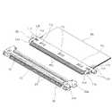
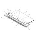
図1〜図14に示された本発明の一実施形態にかかる電気コネクタ組立体は、フレキシブル・プリンテッド・サーキット(FPC)や、フレキシブル・フラット・ケーブル(FFC)等からなる板状信号伝送媒体PSの端末部分を、図示を省略した印刷配線基板上の電子回路に接続するために用いるものであって、特に図2に示される様に板状信号伝送媒体PSの端末部分を連結された本発明の一実施形態にかかるプラグコネクタ10が、印刷配線基板上に形成された配線パターン(図示省略)に半田接続された相手コネクタとしてのリセプタクルコネクタ20に対して、略水平方向に差し込まれることにより嵌合状態になされている。[Electric connector assembly]
An electrical connector assembly according to an embodiment of the present invention shown in FIGS. 1 to 14 is a plate-like signal transmission medium made of a flexible printed circuit (FPC), a flexible flat cable (FFC), or the like. Used to connect the terminal portion of the PS to an electronic circuit on a printed wiring board (not shown), and in particular a book in which the terminal portion of the plate-like signal transmission medium PS is connected as shown in FIG. A
以下において、印刷配線基板の表面の延在方向を「水平方向」とし、その印刷配線基板の表面に垂直な方向を「高さ方向」とする。また、プラグコネクタ10においては、嵌合時における差し込み方向における先端側の端縁部を「前端縁部」とし、それとは反対側の板状信号伝送媒体PSの端末部分が連結される側の端縁部を「後端縁部」とする。また、リセプタクルコネクタ20においては、プラグコネクタ10が嵌合時に差し込まれる側の端縁部を「前端縁部」、その反対側の端縁部を「後端縁部」とする。さらに、これらのプラグコネクタ10及びリセプタクルコネクタ20は、細長状をなすように延在するコネクタ本体部を有しているが、そのコネクタ本体部の延在方向を「コネクタ長手方向」と呼ぶこととする。 Hereinafter, the extending direction of the surface of the printed wiring board is referred to as “horizontal direction”, and the direction perpendicular to the surface of the printed wiring board is referred to as “height direction”. Moreover, in the
さらに、プラグコネクタ10の後端縁部から後方側に延出している板状信号伝送媒体(FPC,FFC)PSは、上述した「コネクタ長手方向」を「板幅方向」として連結されているとともに、その「板幅方向」に直交する方向に延在する部材から構成されていて、複数本の信号線およびグランド線(シールド線)が、「板幅方向」に沿って多極状をなすように隣接して配列されている。 Further, the plate-like signal transmission medium (FPC, FFC) PS extending rearward from the rear edge of the
[プラグコネクタについて]
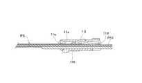
このような電気コネクタ組立体の一方側の電気コネクタを構成しているプラグコネクタ10のコネクタ本体部は、一般的な電気コネクタが備えている合成樹脂等の絶縁性材料からなる絶縁基体(絶縁ハウジング)を有しておらず、電磁波ノイズ等を遮断するための導電性シェル11の内部に形成された媒体収容空間内に、板状信号伝送媒体(FPC,FFC)PSの端末部分が挿入されて固定された構成になされている。このときの導電性シェル11は、図3に示される様に板状信号伝送媒体PSの端末部分を上下から挟む上部シェル11aおよび下部シェル11bを備えた一体的な構造体から形成されているが、詳細な構造については後段において説明する。[About plug connectors]
The connector main body portion of the
一方、図8,9に示される様に板状信号伝送媒体(FPC,FFC)PSは、上述したように板幅方向に沿って複数本の信号線およびグランド線が、可撓性を有する絶縁被覆材の内部に多極状をなすように配列されているが、本実施形態における絶縁被覆部材としては、上述した信号線およびグランド線上に下層を構成するように貼着された絶縁性カバーフィルムが用いられているとともに、さらにその絶縁性カバーフィルム上からシールドテープが上層を構成するように積層された構造になされている。 On the other hand, as shown in FIGS. 8 and 9, in the plate-like signal transmission medium (FPC, FFC) PS, as described above, a plurality of signal lines and ground lines are insulated along the plate width direction. An insulating cover film that is arranged so as to form a multipolar shape inside the covering material, but is attached to form the lower layer on the signal line and the ground line as the insulating covering member in the present embodiment. Is used, and a shield tape is laminated on the insulating cover film so as to form an upper layer.
そして、このような絶縁被覆部材は、プラグコネクタ10の媒体収容空間内に挿入される先端縁側の一定領域で剥がされた状態になされており、それによって多極状の電極部が形成されている。すなわち、当該板状信号伝送媒体PSの端末部分においては、複数本の信号線およびグランド線が上方側に露出された状態になされており、その信号線およびグランド線の露出部分によって複数の接続端子部(コンタクト部)PS1からなる多極状電極部が形成されている。なお、これらの接続端子部PS1の下面側部分(非露出側部分)には、当該接続端子部PS1の下面全体を覆うように絶縁被覆材が被着されている。 And such an insulation coating member is made into the state peeled in the fixed area | region by the side of the front end edge inserted in the medium accommodation space of the
このとき、本実施形態における接続端子部PS1は、板幅方向の両側部分にグランド線を露出させたグランド端子を備えているとともに、それらの板幅方向の両側部分のグランド端子同士の間には、信号線を露出させることで形成された信号線端子が所定のピッチをなすように配列されている。このような複数の接続端子部PS1を有する板状信号伝送媒体(FPC,FFC)PSの端末部分は、上述した導電性シェル11の内部に挿入されて固定されるが、当該板状信号伝送媒体PSの固定状態においては、接続端子部(多極状電極部)PS1が、導電性シェル11の前端縁から前方に向かって突出するように配置され、後述する相手コネクタとしてのリセプタクルコネクタ20内に挿入されて電気的な接触が行われるようになっている。 At this time, the connection terminal portion PS1 in the present embodiment includes ground terminals with ground lines exposed on both side portions in the plate width direction, and between the ground terminals on both side portions in the plate width direction. The signal line terminals formed by exposing the signal lines are arranged at a predetermined pitch. The terminal portion of the plate-shaped signal transmission medium (FPC, FFC) PS having such a plurality of connection terminal portions PS1 is inserted and fixed inside the
また、板状信号伝送媒体(FPC,FFC)PSの板幅方向における両側端縁には、上述した接続端子部(多極状電極部)PS1のやや後方側に相当する部分に、位置決め部PS2,PS2が設けられている。これらの各位置決め部PS2は、平面略矩形状をなして板幅方向の外方に突出するように形成されているが、当該各位置決め部PS2の上面には上述したグランド端子が形成されている。そのグランド端子の一部は、絶縁被覆部材の下層を構成している絶縁性カバーフィルムにより覆われているが、上層を構成しているシールドテープについては、コネクタ長手方向の両側部分がコーナー状にカットされて位置決め部PS2を覆わない形状になされている。また、これらの各位置決め部PS2には、後述するように導電性シェル11に設けられた抜止め係合爪11c,11cが係合する構成になされており、それらの抜止め係合爪11c,11cが位置決め部PS2,PS2に係合することによって、板状信号伝送媒体PSの全体が、予め定められた所定の位置に保持されるようになっている。 Further, on both side edges in the plate width direction of the plate-like signal transmission medium (FPC, FFC) PS, a positioning portion PS2 is provided at a portion corresponding to the slightly rear side of the connection terminal portion (multipolar electrode portion) PS1 described above. , PS2 are provided. Each of these positioning portions PS2 has a substantially rectangular shape and is formed so as to protrude outward in the plate width direction, and the above-described ground terminal is formed on the upper surface of each positioning portion PS2. . A part of the ground terminal is covered with an insulating cover film that forms the lower layer of the insulating coating member, but the shield tape that forms the upper layer has corners on both sides in the connector longitudinal direction. It is cut and does not cover the positioning part PS2. Each positioning portion PS2 is configured to engage with retaining
この点を詳しく説明すると、前述したように導電性シェル11は、図3、図5に示される様に板状信号伝送媒体(FPC,FFC)PSの端末部分を上下から挟む上部シェル11aおよび下部シェル11bから構成されているが、それらの上部シェル11aおよび下部シェル11bの前端縁部分は、コネクタ長手方向の両側部分に配置された一対のシェル連結部11d,11dにより一体的に繋げられている。シェル連結部11d,11dは、帯板状部材を側面略コの字状をなすように折り曲げ形成されており、当該シェル連結部11d,11dを介して一体的に連結された上部シェル11aと下部シェル11bとが所定の間隔をなして略平行に配置されている。これらの上部シェル11aおよび下部シェル11b同士の平行対面部分には、板状信号伝送媒体PSを挿入するための媒体収容空間が形成されている。 This point will be described in detail. As described above, the
上述したシェル連結部11d,11dは、導電性シェル11の前端側部分、つまり板状信号伝送媒体(FPC,FFC)PSを上述した媒体収容空間内に挿入し終える側の端縁における両側部分に配置されており、当該両シェル連結部11d,11d同士の間部分に、板状信号伝送媒体PSの接続端子部PS1が貫通する突出開口部が、コネクタ長手方向に細長状に延在するように形成されている。また、この導電性シェル11に設けられた突出開口部に対して反対側に対向する部分、つまり媒体収容空間における後端側の部分には、板状信号伝送媒体PSの各位置決め部PS2,PS2を含めた当該板状信号伝送媒体PSの板幅全体を挿入可能とする挿入開口部がコネクタ長手方向に細長状に延在するように形成されている。そして、その導電性シェル11における後方側の挿入開口部を通して、板状信号伝送媒体PSの接続端子部PS1が媒体収容空間に挿入された後、さらに前方側に挿入されていくことによって、当該板状信号伝送媒体PSの接続端子部PS1が、上述した突出開口部を通して前方側に向かって突き出すように突出し、板状信号伝送媒体PSの各位置決め部PS2,PS2を含めた端末部分が媒体収容空間内に収納される構成になされている。 The
また、図4、5に示される様に上述した導電性シェル11の突出開口部におけるコネクタ長手方向の両側外方部分には、外方固定部11h,11hが外方に突出するように形成されており、それらの外方固定部11h,11hが上下方向に嵌り合うことで、上部シェル11aと下部シェル11bとが強固に固定される構成になされている。すなわち、外方固定部11h,11hから突出開口部に至る部位には、上部シェル11aおよび下部シェル11bの前端部分を側面略Lの字状をなすように折り曲げ形成したシェル固定片11e,11eが形成されており、それらのシェル固定片11e,11eにおける上部シェル11a側に設けられたものと、下部シェル11b側に設けられたものとが、コネクタ前後方向において重合するようにして固着されている。なお、上部シェル11aと下部シェル11bの外方固定部11h,11hの間の空間には、プラグコネクタ10とリセプタクルコネクタ20とを接続した後に接続状態を維持するロックバーの軸端を保持することができる。 Also, as shown in FIGS. 4 and 5, the
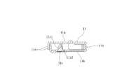
さらに、図5〜図7に示されるように、下部シェル11bにおけるコネクタ長手方向の両側部分には、一対の抜止め係止爪11c,11cが一体的に形成されている。これらの抜止め係止爪11c,11cは、当該抜止め係止爪11c,11cを支持している弾性アーム11f,11fとともに下部シェル11bの一部を打ち抜くようにして形成されている。このときの各弾性アーム11fは、下部シェル11bの前端縁近傍部分から前方側に向かって片持ち状をなして延出するように形成されており、それらの各弾性アーム11fの自由端縁部分に、抜止め係止爪11cがそれぞれ設けられている。 Further, as shown in FIGS. 5 to 7, a pair of retaining locking
より具体的には、上述した各弾性アーム11fは、下部シェル11bの前端縁側に片持ち構造の根本部分を有するように形成されているとともに、その根本部分から後方に向かって連続的に板幅が縮小しながら斜め外方に向かって延出する形状になされている。そして、当該弾性アーム11fの延出側先端部分である自由端縁部分が、上方に立ち上げられるように略直角に折り曲げられていることで、上述した各抜止め係止爪11cの形成加工がなされている。これらの各抜止め係止爪11cは、特に図5に示される様に側面視において略三角形状をなすように形成されており、前方側から後方側に向かって連続的に高くなる傾斜状案内辺部11c1と、その傾斜案内辺部11c1の頂部から下方に向かって略直線状に下降する直線状保持辺部11c2とを有している。 More specifically, each
それらの各抜止め係止爪11cの傾斜状案内辺部11c1は、前述したように導電性シェル11の挿入開口部から挿入された板状信号伝送媒体(FPC,FFC)PSの位置決め部PS2に対して当接可能となる位置関係になされている。すなわち、図11、12、および図14に示される様に板状信号伝送媒体PSの位置決め部PS2における挿入方向先端縁部が、抜止め係止爪11cの傾斜状案内辺部11c1に当接すると、当該傾斜案内辺部11c1に発生する下方分力によって抜止め係止爪11cの全体が、上述した弾性アーム11fの弾性力に抗して下降方向に変位し、その抜止め係止爪11cの頂部に対して板状信号伝送媒体PSの下方側の表面が乗り上げるようになっている。板状信号伝送媒体PSの挿入がさらに進んで、当該板状信号伝送媒体PSの位置決め部PS2の後端縁部が抜止め係止爪11cを通り越した時点で、弾性アーム11fの弾性復帰付勢力によって抜止め係止爪11cが元の位置まで上昇するように変位し、それによって抜止め係止爪11cの直線状保持辺部11c2が、板状信号伝送媒体PSの位置決め部PS2の後端縁部に当接し、それによって係合状態になされる。 The inclined guide side portions 11c1 of each of the retaining
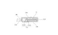
一方、図6、7に示される様に前述した導電性シェル11のシェル連結部11d,11dの内壁近傍部分には、導電性シェル11の挿入開口部から挿入された板状信号伝送媒体(FPC,FFC)PSに対する突当て弾性バネ部11g,11gが配置されている。これらの各突当て弾性バネ部11gは、下部シェル11bのコネクタ長手方向における両端部分に設けられた摺接弾性バネ11mを介して延出する帯板状部材から形成されており、板状信号伝送媒体PSの位置決め部PS2が有する外形形状に沿うように延在している。 On the other hand, as shown in FIGS. 6 and 7, the plate-like signal transmission medium (FPC) inserted from the insertion opening of the
より具体的には、まず摺接弾性バネ11mは、下部シェル11bのコネクタ長手方向における両端縁部を基部として斜め前方側に延出する片持ち状部材から形成されており、前記基部からコネクタ内方側(コネクタ中心側)に向かって斜め前方側に向かって延出している。そして、前述したように板状信号伝送媒体(FPC,FFC)PSの挿入が行われた際に、当該板状信号伝送媒体PSに設けられた位置決め部PS2の挿入方向前端側の角部が、上述した摺接弾性バネ11mの途中部分に当接する位置関係になされている。 More specifically, the slidable
また、突当て弾性バネ部11gは、摺接弾性バネ11mの延出方向の先端部からコネクタ内方側(コネクタ中心側)に向かって折れ曲がるようにして片持ち状に延出しており、図11、14に示される様に最終的な挿入位置まで挿入された板状信号伝送媒体(FPC,FFC)PSの位置決め部PS2に対して、コネクタ長手方向の前端縁に沿って延在するように形成されている。このような摺接弾性バネ11mおよび突当て弾性バネ部11gは、それぞれ上述した板状信号伝送媒体PSの位置決め部PS2の前端角部および前端縁部に沿うように延在しているが、片持ち状部材から形成されていることによって弾性可撓性を有する板バネ状部材になされている。 Further, the abutting
そして、板状信号伝送媒体(FPC,FFC)PSが媒体収容空間内に挿入された際においては、まず板状信号伝送媒体PSの位置決め部PS2の前端角部が摺接弾性バネ11mに当接し、当該摺接弾性バネ部材11mの弾性付勢力によって位置決め部PS2を含む板状信号伝送媒体PSの全体が板幅方向の予め決められた位置まで移動されるようになっている。 When the plate-shaped signal transmission medium (FPC, FFC) PS is inserted into the medium housing space, the front end corner of the positioning portion PS2 of the plate-shaped signal transmission medium PS first contacts the sliding
さらに、板状信号伝送媒体(FPC,FFC)PSが、媒体収容空間の最終挿入位置まで挿入された際においては、上述した突当て弾性バネ部11gに対して位置決め部PS2の前方側端が前方側から当接し、当該突当て弾性バネ部11gの弾性復帰付勢力によって、位置決め部PS2が後方側に押し戻される。その結果、前述した抜止め係止爪11cの直線状保持辺部11c2に対して位置決め部PS2の後方側端縁部が押し付けられるようになっている。 Further, when the plate-like signal transmission medium (FPC, FFC) PS is inserted to the final insertion position of the medium accommodating space, the front end of the positioning part PS2 is forward with respect to the above-described abutting
さらに、図10、13に示される様に導電性シェル11における上部シェル11aには、当該上部シェル11aの表面に、導電性シェル11を接続端子部PS1から非接触に保持する短絡防止部11jが、コネクタ長手方向に沿って3体のものが並列するように設けられている。これらの各短絡防止部11jは、導電性シェル11の上部シェル11aから媒体収容空間の内方に向かって突出するようにプレス加工された内方突部から形成されており、媒体収容空間における最終位置まで挿入された板状信号伝送媒体(FPC,FFC)PSの絶縁被覆部分に対して、当該各短絡防止部11jが上方側から対向するように設けられている。 Further, as shown in FIGS. 10 and 13, the
さらにまた、上部シェル11aには、上述した短絡防止部11jのコネクタ長手方向の外方部分に、一対のグランドコンタクト11k,11kが形成されている。それらの各グランドコンタクト11kは、上部シェル11aから内方側の媒体収容空間に向かって片持ち状をなして突出するように切り欠き形成されている。これらの各グランドコンタクト11kは、板状信号伝送媒体(FPC,FFC)PSのグランド端子に接触する配置関係になされており、板状信号伝送媒体PSが最終位置まで挿入された際にグランド接続が行われるようになっている。Furthermore, a pair of
[リセプタクルコネクタについて]
一方、電気コネクタ組立体における他方の相手コネクタを構成しているリセプタクルコネクタ20は、特に図1及び図2に示されているように、合成樹脂等の絶縁材料によって形成された絶縁ハウジング21を有しているとともに、その絶縁ハウジング21の外表面を覆って外部からの電磁波ノイズ等を遮断する導電性シェル22を備えている。[Receptacle connector]
On the other hand, the
絶縁ハウジング21には、複数の導電コンタクト23が、コネクタ長手方向に沿って多極状をなすようにして適宜にピッチ間隔で配列されている。それらの各導電コンタクト23は、弾性を有するビーム状の金属材料が屈曲されて形成されており、前記絶縁ハウジング21に設けられた溝状部内に前後方向に延在するように配置されている。これらの各導電コンタクト23は、隣接するもの同士が略同一形状をなすように形成されている。 In the insulating
一方、前記各導電コンタクト23の後端側部分には、下方側に向かって階段状をなすように折り曲げ形成された接続脚部が設けられており、その接続脚部が、図示を省略した印刷配線基板上に形成された信号伝送用の印刷配線パターン(導電路)上に半田接合されて電気的に接続されている。このときの半田接合は、多極配列方向の全てのものに対して一括して行われる。 On the other hand, the rear end portion of each
また、上述した各導電コンタクト23の前端側部分には、図示を省略した接点部が設けられており、それらの各接点部が、リセプタクルコネクタ20に嵌合されたプラグコネクタ10の接続端子部PS1の各接続端子に対して上方側から弾性的に接触される配置関係になされており、それによって前記接点部から接続脚部を介して印刷配線基板に至る信号伝送回路が形成される構造になされている。 Further, a contact portion (not shown) is provided at the front end portion of each
さらに、導電性シェル22は、その上下前端縁部において、当該リセプタクルコネクタ20に嵌合されたプラグコネクタ10の上部シェル11aの上面部分および下部シェル11bの下面部分に対して弾性的に面接触する構成になされているとともに、導電性シェル22におけるコネクタ長手方向の両端部分には、複数のホールドダウン22aが、コネクタ長手方向の外方側及び後端側に向かって略水平に延出するように設けられている。これらのホールドダウン22aは、印刷配線基板上に形成された接地用の印刷配線パターン(導電路)上に半田接合されて電気的に接続されており、それによって、導電性シェル22から印刷配線基板に至るグランド回路が形成されるとともに、リセプタクルコネクタ20の全体が固定されるようになっている。 Further, the
このような実施形態にかかるプラグコネクタ10においては、板状信号伝送媒体(FPC,FFC)PSが、導電性シェル11の後端に設けられた挿入開口部を通して媒体収容空間内に挿入されると、板状信号伝送媒体PSの位置決め部PS2が抜止め係止爪11cに当接する。その抜止め係止爪11cは、下方に変位して板状信号伝送媒体PSの下面側が抜止め係止爪11cに乗り上げ、その後に抜止め係止爪11cが元の位置まで上昇変位して弾性復帰することによって、板状信号伝送媒体PSの位置決め部PS2に対して抜止め係止爪11cの直線状保持辺部11c2が後方側から係合状態となる。その結果、板状信号伝送媒体PSが、導電性シェル11に対してガタツキ無く保持されることとなり、板状信号伝送媒体PSを挿入するだけで当該板状信号伝送媒体PSの組付けが容易かつ良好に行われる。 In the
特に、本実施形態においては、突当て弾性バネ部11gの押し戻し付勢力によって、板状信号伝送媒体(FPC,FFC)PSの位置決め部PS2を後方側の抜止め係止爪11cに押し付ける構成になされていることから、板状信号伝送媒体PSは、挿入方向の前後から弾性的に圧接状態になされて確実に保持され、当該板状信号伝送媒体PSの保持性が高められるようになっている。このように本実施形態においては、板状信号伝送媒体PSに対する抜止め係止爪11cの係合が、位置決め部PS2を介して確実に行われることによって、板状信号伝送媒体PSの保持性が高められる構成になされている。 In particular, in the present embodiment, the positioning portion PS2 of the plate-shaped signal transmission medium (FPC, FFC) PS is pressed against the rear
また、本実施形態においては、導電性シェル11に外力等が付加されることによって変形されようとした場合に、短絡防止部11jが板状信号伝送媒体(FPC,FFC)PSの絶縁被覆部分に当接し、導電性シェル11がそれ以上変形しなくなり、導電性シェル11の接続端子部(多極状電極部)PS1に対する導電性シェル11の接触が防止されることとなり、伝送信号の短絡等の不具合が良好に回避されるようになっている。 Further, in the present embodiment, when the
さらに本実施形態においては、導電性シェル11の媒体収容空間内に挿入された板状信号伝送媒体(FPC,FFC)PSが、摺接弾性バネ部材11mの弾性付勢力によって板幅方向の予め決められた位置まで移動されることから、板状信号伝送媒体PSの挿入時における初期状態にかかわらず当該板状信号伝送媒体が板幅方向の適正位置に保持される。 Furthermore, in this embodiment, the plate-like signal transmission medium (FPC, FFC) PS inserted in the medium accommodation space of the
一方、上述した実施形態にかかる導電性シェル11は、上部シェル片11aおよび下部シェル片11bを含む全体が一体的に構成されていることから、複数体の導電性シェル11,11,・・・が、例えばキャリア等によって連続的に繋げられた中間工程を採用することが可能となっている。このようにすれば、導電性シェル11の製造が一括して行われることから、極めて効率的な製造が可能となる。 On the other hand, since the
以上、本発明者によってなされた発明を実施形態に基づき具体的に説明したが、本実施形態は上述した実施形態に限定されるものではなく、その要旨を逸脱しない範囲で種々変形可能であるというのはいうまでもない。 As mentioned above, although the invention made by the present inventor has been specifically described based on the embodiment, the present embodiment is not limited to the above-described embodiment, and various modifications can be made without departing from the scope of the invention. Needless to say.
例えば、上述した実施形態においては、板状信号伝送媒体PSに設けられた位置決め部PS2が、板幅方向外方へ突出する形状になされているが、板幅方向に窪む形状とすることも可能であり、また板厚方向に突出する柱状形状のものや、窪む穴形状とすることも可能である。 For example, in the above-described embodiment, the positioning part PS2 provided on the plate-shaped signal transmission medium PS is formed to protrude outward in the plate width direction, but may be formed to be recessed in the plate width direction. It is also possible to use a columnar shape protruding in the thickness direction or a hollow shape.
また、上述した実施形態における接続端子部(多極状電極部)は、グランド端子が信号端子の外側に配置された構成になされているが、当該グランド端子は、信号端子に対してその他の配置関係とすることも当然可能である。また、グランド端子を廃止した信号端子のみの構成とすることもできる。 Moreover, although the connection terminal part (multipolar electrode part) in embodiment mentioned above is made into the structure by which the ground terminal is arrange | positioned on the outer side of a signal terminal, the said ground terminal is other arrangement | positioning with respect to a signal terminal. Of course, it is possible to have a relationship. Moreover, it is also possible to adopt a configuration with only signal terminals that eliminate the ground terminal.
さらにまた、上述した実施形態における抜止め係止爪11cは、上下方向に弾性変位する構成になされているが、板状信号伝送媒体の挿入方向と直交する方向であれば、その他の方向に弾性変位可能とするように支持することも可能である。例えば、本実施形態では、抜止め係止爪11cを板状信号伝送媒体の板厚方向に弾性変位するように下部シェル11bに設けたが、板状信号伝送媒体の板幅方向に弾性変位するように導電性シェルの側面に設けても良い。 Furthermore, the
また、上述した実施形態は、水平嵌合型のプラグコネクタに対して本発明を適用したものであるが、垂直嵌合型のプラグコネクタに対しても同様に適用することができる。 Moreover, although embodiment mentioned above applies this invention with respect to a horizontal fitting type plug connector, it can apply similarly also to a vertical fitting type plug connector.
以上のように本実施形態は、各種電気機器に使用される多種多様な電気コネクタに対して広く適用することが可能である As described above, the present embodiment can be widely applied to a wide variety of electrical connectors used in various electrical devices.
PS 板状信号伝送媒体
10 プラグコネクタ
11 導電性シェル
11a 上部シェル
11b 下部シェル
11c 抜止め係合爪
11c1 傾斜状案内辺部
11c2 直線状保持辺部
11d シェル連結部
11e シェル固定片
11f 弾性アーム
11g 突当て弾性バネ部
11h 外方固定部
11j 短絡防止部
11k グランドコンタクト
11m 摺接弾性バネ部
20 リセプタクルコネクタ(相手コネクタ)
21 絶縁ハウジング
22 導電性シェル
22a ホールドダウン
23 導電コンタクト
PS 板状信号伝送媒体(FPC,FFC)
PS1 接続端子部(多極状電極部)
PS2 位置決め部PS plate-like
21 Insulating
PS1 connection terminal (multipolar electrode)
PS2 positioning part
Claims (6)
Translated fromJapanese前記導電性シェルに、前記板状信号伝送媒体の端末部分が挿入される媒体収容空間が形成されているとともに、
前記媒体収容空間内に挿入された前記板状信号伝送媒体の一部に係合することで当該板状信号伝送媒体を保持する抜止め係止爪が、前記導電性シェルに設けられたものであって、
前記抜止め係止爪は、前記板状信号伝送媒体の挿入方向と直交する方向に弾性変位可能に支持され、
その媒体収容空間内に挿入された前記板状信号伝送媒体の一部が、前記抜止め係止爪に当接することで当該抜止め係止爪が弾性変位し、その際における前記抜止め係止爪の弾性復帰付勢力によって前記板状信号伝送媒体の一部に前記抜止め係止爪が係合する構成になされていることを特徴とするプラグコネクタ。In the plug connector configured such that the terminal portion of the plate-shaped signal transmission medium is attached so as to protrude from the conductive shell, and the portion including the terminal portion of the plate-shaped signal transmission medium is inserted into the mating connector.
In the conductive shell, a medium accommodating space into which a terminal portion of the plate-shaped signal transmission medium is inserted is formed,
A retaining claw for holding the plate-shaped signal transmission medium by engaging with a part of the plate-shaped signal transmission medium inserted into the medium accommodating space is provided on the conductive shell. There,
The retaining locking claw is supported so as to be elastically displaceable in a direction orthogonal to the insertion direction of the plate-shaped signal transmission medium,
A part of the plate-shaped signal transmission medium inserted into the medium accommodating space abuts against the retaining latching claw, so that the retaining latching claw is elastically displaced, and the retaining latching at that time A plug connector, wherein the retaining latching pawl is engaged with a part of the plate-like signal transmission medium by an elastic return biasing force of the pawl.
当該突当て弾性バネ部の弾性復帰付勢力によって前記板状信号伝送媒体が前記抜止め係止爪側に押し付けられる構成になされていることを特徴とする請求項1記載のプラグコネクタ。The conductive shell is provided with an abutting elastic spring portion that comes into contact with a part of the plate-shaped signal transmission medium inserted into the medium accommodating space of the conductive shell and elastically displaces in the insertion direction,
The plug connector according to claim 1, wherein the plate-like signal transmission medium is pressed against the retaining latching claw side by an elastic return biasing force of the abutting elastic spring portion.
その位置決め部に、前記抜止め係止爪が係合する構成になされていることを特徴とする請求項1記載のプラグコネクタ。The plate-like signal transmission medium is provided with a positioning portion formed so as to protrude or dent in the plate width direction or plate thickness direction of the plate-like signal transmission medium,
The plug connector according to claim 1, wherein the positioning locking portion is configured to engage the retaining locking claw.
当該短絡防止部は、前記媒体収容空間内に挿入された前記板状信号伝送媒体の絶縁部分に対面するように配置されていることを特徴とする請求項1記載のプラグコネクタ。Provided on the surface of the conductive shell is a short-circuit prevention portion that holds the conductive shell in a non-contact manner fromthe connection terminalportionexposed at the terminal portion of the plate-like signal transmission medium ,
The plug connector according to claim 1, wherein the short-circuit prevention unit is disposed so as to face an insulating portion of the plate-shaped signal transmission medium inserted into the medium housing space.
A method for manufacturing a plug connector, comprising: integrally connecting a plurality of conductive shells according to any one of claims 1 to 5.
Priority Applications (5)
| Application Number | Priority Date | Filing Date | Title |
|---|---|---|---|
| JP2013114822AJP5704364B2 (en) | 2013-05-31 | 2013-05-31 | Plug connector and manufacturing method thereof |
| TW103116216ATWI532262B (en) | 2013-05-31 | 2014-05-07 | Plug connector and method of manufacturing the same |
| US14/283,375US9343832B2 (en) | 2013-05-31 | 2014-05-21 | Plug connector and method of manufacturing the same |
| KR1020140063516AKR101549338B1 (en) | 2013-05-31 | 2014-05-27 | Plug connector and method of manufacturing the same |
| CN201410235011.8ACN104218367B (en) | 2013-05-31 | 2014-05-30 | Plug connector and manufacture method thereof |
Applications Claiming Priority (1)
| Application Number | Priority Date | Filing Date | Title |
|---|---|---|---|
| JP2013114822AJP5704364B2 (en) | 2013-05-31 | 2013-05-31 | Plug connector and manufacturing method thereof |
Publications (2)
| Publication Number | Publication Date |
|---|---|
| JP2014235794A JP2014235794A (en) | 2014-12-15 |
| JP5704364B2true JP5704364B2 (en) | 2015-04-22 |
Family
ID=51985607
Family Applications (1)
| Application Number | Title | Priority Date | Filing Date |
|---|---|---|---|
| JP2013114822AActiveJP5704364B2 (en) | 2013-05-31 | 2013-05-31 | Plug connector and manufacturing method thereof |
Country Status (5)
| Country | Link |
|---|---|
| US (1) | US9343832B2 (en) |
| JP (1) | JP5704364B2 (en) |
| KR (1) | KR101549338B1 (en) |
| CN (1) | CN104218367B (en) |
| TW (1) | TWI532262B (en) |
Families Citing this family (7)
| Publication number | Priority date | Publication date | Assignee | Title |
|---|---|---|---|---|
| SG196703A1 (en)* | 2012-08-03 | 2014-02-13 | Fci Connectors Singapore Pte | Shielded flexible circuit connector |
| JP1521799S (en)* | 2014-07-23 | 2015-04-20 | ||
| JP6015971B2 (en)* | 2014-10-02 | 2016-10-26 | 第一精工株式会社 | Plug connector |
| JP6394524B2 (en)* | 2015-07-10 | 2018-09-26 | 株式会社オートネットワーク技術研究所 | Electromagnetic shield member and wiring device with electromagnetic shield member |
| JP6516208B2 (en)* | 2017-04-27 | 2019-05-22 | 第一精工株式会社 | Electrical connector and electrical connector device |
| JP2019220339A (en)* | 2018-06-20 | 2019-12-26 | ヒロセ電機株式会社 | Electric connector with circuit board |
| CN110911876B (en)* | 2019-12-17 | 2024-11-19 | 昆山嘉华电子有限公司 | Electrical connector assembly |
Family Cites Families (24)
| Publication number | Priority date | Publication date | Assignee | Title |
|---|---|---|---|---|
| JP2961711B2 (en) | 1993-05-21 | 1999-10-12 | 株式会社テクセル | Zipper connector |
| JP2002100426A (en)* | 2000-09-25 | 2002-04-05 | Calsonic Kansei Corp | Connector for flexible flat cable connection |
| JP2002100425A (en)* | 2000-09-25 | 2002-04-05 | Calsonic Kansei Corp | Connector for flexible flat cable |
| JP3380539B2 (en)* | 2000-10-13 | 2003-02-24 | 山一電機株式会社 | Flat cable connector |
| US6793527B2 (en)* | 2001-06-14 | 2004-09-21 | Sumitomo Wiring Systems, Ltd. | Connector |
| JP2002373739A (en)* | 2001-06-14 | 2002-12-26 | Sumitomo Wiring Syst Ltd | Connector for flat cable |
| JP3680767B2 (en)* | 2001-06-14 | 2005-08-10 | 住友電装株式会社 | Flat cable connector |
| US6981891B1 (en)* | 2004-10-19 | 2006-01-03 | Alex Huang | Flexible flat cable connector |
| JP4090060B2 (en) | 2004-12-20 | 2008-05-28 | 日本航空電子工業株式会社 | connector |
| JP4044937B2 (en) | 2005-03-11 | 2008-02-06 | イリソ電子工業株式会社 | connector |
| JP4279823B2 (en) | 2005-10-26 | 2009-06-17 | 日本航空電子工業株式会社 | connector |
| JP4168104B2 (en) | 2006-09-21 | 2008-10-22 | 日本航空電子工業株式会社 | connector |
| CN201160151Y (en)* | 2008-01-05 | 2008-12-03 | 富士康(昆山)电脑接插件有限公司 | Cable Connector Assembly |
| TWM371991U (en) | 2009-06-30 | 2010-01-01 | P Two Ind Inc | The electrical connector |
| JP4915880B2 (en)* | 2009-09-25 | 2012-04-11 | ヒロセ電機株式会社 | Electrical connector with shell |
| JP4982770B2 (en) | 2009-12-04 | 2012-07-25 | 第一精工株式会社 | Connector device |
| US8287311B2 (en)* | 2010-01-15 | 2012-10-16 | P-Two Industries Inc. | Electrical connector and assembling method thereof |
| JP5019079B2 (en)* | 2010-03-10 | 2012-09-05 | 第一精工株式会社 | Connector device |
| JP5063748B2 (en)* | 2010-06-30 | 2012-10-31 | 日本航空電子工業株式会社 | connector |
| JP5813349B2 (en)* | 2011-03-29 | 2015-11-17 | 日本航空電子工業株式会社 | Connector and connection object |
| CN202183485U (en) | 2011-08-29 | 2012-04-04 | 东莞宇球电子有限公司 | Cable connector structure |
| US20130164977A1 (en)* | 2011-12-21 | 2013-06-27 | Guang-Li Huang | Electrical connector |
| JP5621999B2 (en)* | 2012-03-09 | 2014-11-12 | 第一精工株式会社 | Connector device |
| CN202564593U (en) | 2012-04-26 | 2012-11-28 | 东莞市锦润电子有限公司 | Connector for flat circuit board |
- 2013
- 2013-05-31JPJP2013114822Apatent/JP5704364B2/enactiveActive
- 2014
- 2014-05-07TWTW103116216Apatent/TWI532262B/ennot_activeIP Right Cessation
- 2014-05-21USUS14/283,375patent/US9343832B2/enactiveActive
- 2014-05-27KRKR1020140063516Apatent/KR101549338B1/ennot_activeExpired - Fee Related
- 2014-05-30CNCN201410235011.8Apatent/CN104218367B/enactiveActive
Also Published As
| Publication number | Publication date |
|---|---|
| CN104218367A (en) | 2014-12-17 |
| KR101549338B1 (en) | 2015-09-01 |
| TW201505275A (en) | 2015-02-01 |
| US20140357108A1 (en) | 2014-12-04 |
| KR20140141478A (en) | 2014-12-10 |
| JP2014235794A (en) | 2014-12-15 |
| CN104218367B (en) | 2016-08-17 |
| US9343832B2 (en) | 2016-05-17 |
| TWI532262B (en) | 2016-05-01 |
Similar Documents
| Publication | Publication Date | Title |
|---|---|---|
| JP5704364B2 (en) | Plug connector and manufacturing method thereof | |
| JP4493710B2 (en) | Electrical connector | |
| JP4618745B1 (en) | Electrical connector | |
| US8317543B2 (en) | Electrical connector | |
| JP6015971B2 (en) | Plug connector | |
| JP6299733B2 (en) | Electrical connector | |
| JP5947640B2 (en) | Connection structure of terminal fitting and board | |
| JP2008277020A (en) | Electrical connector and manufacturing method thereof | |
| JP5704365B2 (en) | Plug connector and manufacturing method thereof | |
| JP6069008B2 (en) | Connector device | |
| JP5650487B2 (en) | connector | |
| JP2011192616A (en) | Terminal connector | |
| US9755339B2 (en) | Connecting structure of connector and flat circuit body | |
| JP6770250B2 (en) | Electrical connector | |
| JP5335630B2 (en) | Wire-to-board connector | |
| CN2886853Y (en) | Electric connector | |
| JP7203700B2 (en) | Connector shield mounting structure | |
| JP2002095135A (en) | Circuit board electrical connection structure | |
| US20140220814A1 (en) | Connector | |
| JP6520417B2 (en) | Electrical connector and electrical connector device | |
| JP2014072124A (en) | Connector device |
Legal Events
| Date | Code | Title | Description |
|---|---|---|---|
| A131 | Notification of reasons for refusal | Free format text:JAPANESE INTERMEDIATE CODE: A131 Effective date:20141203 | |
| A521 | Request for written amendment filed | Free format text:JAPANESE INTERMEDIATE CODE: A523 Effective date:20150113 | |
| TRDD | Decision of grant or rejection written | ||
| A01 | Written decision to grant a patent or to grant a registration (utility model) | Free format text:JAPANESE INTERMEDIATE CODE: A01 Effective date:20150128 | |
| A61 | First payment of annual fees (during grant procedure) | Free format text:JAPANESE INTERMEDIATE CODE: A61 Effective date:20150210 | |
| R150 | Certificate of patent or registration of utility model | Ref document number:5704364 Country of ref document:JP Free format text:JAPANESE INTERMEDIATE CODE: R150 | |
| R250 | Receipt of annual fees | Free format text:JAPANESE INTERMEDIATE CODE: R250 | |
| R250 | Receipt of annual fees | Free format text:JAPANESE INTERMEDIATE CODE: R250 | |
| R250 | Receipt of annual fees | Free format text:JAPANESE INTERMEDIATE CODE: R250 | |
| R250 | Receipt of annual fees | Free format text:JAPANESE INTERMEDIATE CODE: R250 | |
| R250 | Receipt of annual fees | Free format text:JAPANESE INTERMEDIATE CODE: R250 | |
| R250 | Receipt of annual fees | Free format text:JAPANESE INTERMEDIATE CODE: R250 | |
| R250 | Receipt of annual fees | Free format text:JAPANESE INTERMEDIATE CODE: R250 | |
| R250 | Receipt of annual fees | Free format text:JAPANESE INTERMEDIATE CODE: R250 |