JP5703335B2 - Valve loader methods, systems, and apparatus - Google Patents
Valve loader methods, systems, and apparatusDownload PDFInfo
- Publication number
- JP5703335B2 JP5703335B2JP2013107784AJP2013107784AJP5703335B2JP 5703335 B2JP5703335 B2JP 5703335B2JP 2013107784 AJP2013107784 AJP 2013107784AJP 2013107784 AJP2013107784 AJP 2013107784AJP 5703335 B2JP5703335 B2JP 5703335B2
- Authority
- JP
- Japan
- Prior art keywords
- catheter
- deployment
- deployment catheter
- valve
- cartridge
- Prior art date
- Legal status (The legal status is an assumption and is not a legal conclusion. Google has not performed a legal analysis and makes no representation as to the accuracy of the status listed.)
- Active
Links
- 238000000034methodMethods0.000titledescription26
- 239000000463materialSubstances0.000claimsdescription27
- 230000006641stabilisationEffects0.000claimsdescription27
- 238000011105stabilizationMethods0.000claimsdescription27
- 229920003023plasticPolymers0.000claimsdescription15
- 239000004033plasticSubstances0.000claimsdescription15
- 239000002184metalSubstances0.000claimsdescription11
- 229910052751metalInorganic materials0.000claimsdescription11
- 229920001343polytetrafluoroethylenePolymers0.000claimsdescription10
- 239000004810polytetrafluoroethyleneSubstances0.000claimsdescription10
- 230000000087stabilizing effectEffects0.000claimsdescription4
- 239000000049pigmentSubstances0.000claimsdescription3
- -1polytetrafluoroethylenePolymers0.000claimsdescription3
- 239000000975dyeSubstances0.000claims2
- 230000007246mechanismEffects0.000description47
- 210000000078clawAnatomy0.000description37
- 230000008569processEffects0.000description8
- 230000008901benefitEffects0.000description7
- 238000000576coating methodMethods0.000description6
- 238000003780insertionMethods0.000description6
- 230000037431insertionEffects0.000description6
- 239000004677NylonSubstances0.000description5
- 239000011248coating agentSubstances0.000description5
- 238000002513implantationMethods0.000description5
- 229920001778nylonPolymers0.000description5
- 229920000642polymerPolymers0.000description4
- 229920001296polysiloxanePolymers0.000description4
- 238000003860storageMethods0.000description4
- 239000004812Fluorinated ethylene propyleneSubstances0.000description3
- 229920002614Polyether block amidePolymers0.000description3
- 239000004809TeflonSubstances0.000description3
- 229920006362Teflon®Polymers0.000description3
- 239000003086colorantSubstances0.000description3
- 230000000875corresponding effectEffects0.000description3
- 230000007423decreaseEffects0.000description3
- 230000000881depressing effectEffects0.000description3
- 229920001971elastomerPolymers0.000description3
- 210000004072lungAnatomy0.000description3
- 229920009441perflouroethylene propylenePolymers0.000description3
- 239000005060rubberSubstances0.000description3
- 150000001336alkenesChemical class0.000description2
- TZCXTZWJZNENPQ-UHFFFAOYSA-Lbarium sulfateChemical compound[Ba+2].[O-]S([O-])(=O)=OTZCXTZWJZNENPQ-UHFFFAOYSA-L0.000description2
- 238000005452bendingMethods0.000description2
- 210000004204blood vesselAnatomy0.000description2
- 239000012530fluidSubstances0.000description2
- 230000013011matingEffects0.000description2
- 238000012986modificationMethods0.000description2
- 230000004048modificationEffects0.000description2
- JRZJOMJEPLMPRA-UHFFFAOYSA-NolefinNatural productsCCCCCCCC=CJRZJOMJEPLMPRA-UHFFFAOYSA-N0.000description2
- 229920002635polyurethanePolymers0.000description2
- 239000004814polyurethaneSubstances0.000description2
- 238000000926separation methodMethods0.000description2
- 229910001220stainless steelInorganic materials0.000description2
- 230000032258transportEffects0.000description2
- 241000723353ChrysanthemumSpecies0.000description1
- 235000005633Chrysanthemum balsamitaNutrition0.000description1
- JOYRKODLDBILNP-UHFFFAOYSA-NEthyl urethaneChemical compoundCCOC(N)=OJOYRKODLDBILNP-UHFFFAOYSA-N0.000description1
- IAYPIBMASNFSPL-UHFFFAOYSA-NEthylene oxideChemical compoundC1CO1IAYPIBMASNFSPL-UHFFFAOYSA-N0.000description1
- 241001465754MetazoaSpecies0.000description1
- 230000003213activating effectEffects0.000description1
- 230000002411adverseEffects0.000description1
- 230000003416augmentationEffects0.000description1
- 230000015572biosynthetic processEffects0.000description1
- 210000001124body fluidAnatomy0.000description1
- 239000010839body fluidSubstances0.000description1
- 230000015556catabolic processEffects0.000description1
- 230000008859changeEffects0.000description1
- 238000003486chemical etchingMethods0.000description1
- 238000004891communicationMethods0.000description1
- 230000000295complement effectEffects0.000description1
- 230000006835compressionEffects0.000description1
- 238000007906compressionMethods0.000description1
- 230000002596correlated effectEffects0.000description1
- 230000008878couplingEffects0.000description1
- 238000010168coupling processMethods0.000description1
- 238000005859coupling reactionMethods0.000description1
- 230000006837decompressionEffects0.000description1
- 238000006731degradation reactionMethods0.000description1
- 230000000994depressogenic effectEffects0.000description1
- 238000010586diagramMethods0.000description1
- 238000011038discontinuous diafiltration by volume reductionMethods0.000description1
- 238000006073displacement reactionMethods0.000description1
- 239000003814drugSubstances0.000description1
- 230000003073embolic effectEffects0.000description1
- 239000000945fillerSubstances0.000description1
- 229920005570flexible polymerPolymers0.000description1
- 238000010438heat treatmentMethods0.000description1
- 239000007943implantSubstances0.000description1
- 230000003993interactionEffects0.000description1
- 229920000126latexPolymers0.000description1
- 239000004816latexSubstances0.000description1
- 238000004519manufacturing processMethods0.000description1
- 239000012528membraneSubstances0.000description1
- 210000000056organAnatomy0.000description1
- 230000002093peripheral effectEffects0.000description1
- 238000003825pressingMethods0.000description1
- 230000002787reinforcementEffects0.000description1
- 239000011347resinSubstances0.000description1
- 229920005989resinPolymers0.000description1
- 239000000523sampleSubstances0.000description1
- 239000010935stainless steelSubstances0.000description1
- 238000001356surgical procedureMethods0.000description1
- 230000001225therapeutic effectEffects0.000description1
- 229920002725thermoplastic elastomerPolymers0.000description1
- 238000012546transferMethods0.000description1
Images


Classifications
- A—HUMAN NECESSITIES
- A61—MEDICAL OR VETERINARY SCIENCE; HYGIENE
- A61F—FILTERS IMPLANTABLE INTO BLOOD VESSELS; PROSTHESES; DEVICES PROVIDING PATENCY TO, OR PREVENTING COLLAPSING OF, TUBULAR STRUCTURES OF THE BODY, e.g. STENTS; ORTHOPAEDIC, NURSING OR CONTRACEPTIVE DEVICES; FOMENTATION; TREATMENT OR PROTECTION OF EYES OR EARS; BANDAGES, DRESSINGS OR ABSORBENT PADS; FIRST-AID KITS
- A61F2/00—Filters implantable into blood vessels; Prostheses, i.e. artificial substitutes or replacements for parts of the body; Appliances for connecting them with the body; Devices providing patency to, or preventing collapsing of, tubular structures of the body, e.g. stents
- A61F2/95—Instruments specially adapted for placement or removal of stents or stent-grafts
- A61F2/9517—Instruments specially adapted for placement or removal of stents or stent-grafts handle assemblies therefor
- A—HUMAN NECESSITIES
- A61—MEDICAL OR VETERINARY SCIENCE; HYGIENE
- A61F—FILTERS IMPLANTABLE INTO BLOOD VESSELS; PROSTHESES; DEVICES PROVIDING PATENCY TO, OR PREVENTING COLLAPSING OF, TUBULAR STRUCTURES OF THE BODY, e.g. STENTS; ORTHOPAEDIC, NURSING OR CONTRACEPTIVE DEVICES; FOMENTATION; TREATMENT OR PROTECTION OF EYES OR EARS; BANDAGES, DRESSINGS OR ABSORBENT PADS; FIRST-AID KITS
- A61F2/00—Filters implantable into blood vessels; Prostheses, i.e. artificial substitutes or replacements for parts of the body; Appliances for connecting them with the body; Devices providing patency to, or preventing collapsing of, tubular structures of the body, e.g. stents
- A61F2/95—Instruments specially adapted for placement or removal of stents or stent-grafts
- A61F2/9522—Means for mounting a stent or stent-graft onto or into a placement instrument
- A61F2/9525—Means for mounting a stent or stent-graft onto or into a placement instrument using a funnel
- A—HUMAN NECESSITIES
- A61—MEDICAL OR VETERINARY SCIENCE; HYGIENE
- A61F—FILTERS IMPLANTABLE INTO BLOOD VESSELS; PROSTHESES; DEVICES PROVIDING PATENCY TO, OR PREVENTING COLLAPSING OF, TUBULAR STRUCTURES OF THE BODY, e.g. STENTS; ORTHOPAEDIC, NURSING OR CONTRACEPTIVE DEVICES; FOMENTATION; TREATMENT OR PROTECTION OF EYES OR EARS; BANDAGES, DRESSINGS OR ABSORBENT PADS; FIRST-AID KITS
- A61F2/00—Filters implantable into blood vessels; Prostheses, i.e. artificial substitutes or replacements for parts of the body; Appliances for connecting them with the body; Devices providing patency to, or preventing collapsing of, tubular structures of the body, e.g. stents
- A61F2/02—Prostheses implantable into the body
- A61F2/24—Heart valves ; Vascular valves, e.g. venous valves; Heart implants, e.g. passive devices for improving the function of the native valve or the heart muscle; Transmyocardial revascularisation [TMR] devices; Valves implantable in the body
- A61F2/2427—Devices for manipulating or deploying heart valves during implantation
- A—HUMAN NECESSITIES
- A61—MEDICAL OR VETERINARY SCIENCE; HYGIENE
- A61F—FILTERS IMPLANTABLE INTO BLOOD VESSELS; PROSTHESES; DEVICES PROVIDING PATENCY TO, OR PREVENTING COLLAPSING OF, TUBULAR STRUCTURES OF THE BODY, e.g. STENTS; ORTHOPAEDIC, NURSING OR CONTRACEPTIVE DEVICES; FOMENTATION; TREATMENT OR PROTECTION OF EYES OR EARS; BANDAGES, DRESSINGS OR ABSORBENT PADS; FIRST-AID KITS
- A61F2/00—Filters implantable into blood vessels; Prostheses, i.e. artificial substitutes or replacements for parts of the body; Appliances for connecting them with the body; Devices providing patency to, or preventing collapsing of, tubular structures of the body, e.g. stents
- A61F2/02—Prostheses implantable into the body
- A61F2/04—Hollow or tubular parts of organs, e.g. bladders, tracheae, bronchi or bile ducts
- A61F2002/043—Bronchi
- A—HUMAN NECESSITIES
- A61—MEDICAL OR VETERINARY SCIENCE; HYGIENE
- A61F—FILTERS IMPLANTABLE INTO BLOOD VESSELS; PROSTHESES; DEVICES PROVIDING PATENCY TO, OR PREVENTING COLLAPSING OF, TUBULAR STRUCTURES OF THE BODY, e.g. STENTS; ORTHOPAEDIC, NURSING OR CONTRACEPTIVE DEVICES; FOMENTATION; TREATMENT OR PROTECTION OF EYES OR EARS; BANDAGES, DRESSINGS OR ABSORBENT PADS; FIRST-AID KITS
- A61F2250/00—Special features of prostheses classified in groups A61F2/00 - A61F2/26 or A61F2/82 or A61F9/00 or A61F11/00 or subgroups thereof
- A61F2250/0058—Additional features; Implant or prostheses properties not otherwise provided for
- A61F2250/008—Alarm means
- Y—GENERAL TAGGING OF NEW TECHNOLOGICAL DEVELOPMENTS; GENERAL TAGGING OF CROSS-SECTIONAL TECHNOLOGIES SPANNING OVER SEVERAL SECTIONS OF THE IPC; TECHNICAL SUBJECTS COVERED BY FORMER USPC CROSS-REFERENCE ART COLLECTIONS [XRACs] AND DIGESTS
- Y10—TECHNICAL SUBJECTS COVERED BY FORMER USPC
- Y10T—TECHNICAL SUBJECTS COVERED BY FORMER US CLASSIFICATION
- Y10T29/00—Metal working
- Y10T29/53—Means to assemble or disassemble
- Y10T29/53039—Means to assemble or disassemble with control means energized in response to activator stimulated by condition sensor
- Y10T29/53061—Responsive to work or work-related machine element
- Y10T29/53078—Responsive to work or work-related machine element with means to fasten by frictional fitting
- Y—GENERAL TAGGING OF NEW TECHNOLOGICAL DEVELOPMENTS; GENERAL TAGGING OF CROSS-SECTIONAL TECHNOLOGIES SPANNING OVER SEVERAL SECTIONS OF THE IPC; TECHNICAL SUBJECTS COVERED BY FORMER USPC CROSS-REFERENCE ART COLLECTIONS [XRACs] AND DIGESTS
- Y10—TECHNICAL SUBJECTS COVERED BY FORMER USPC
- Y10T—TECHNICAL SUBJECTS COVERED BY FORMER US CLASSIFICATION
- Y10T29/00—Metal working
- Y10T29/53—Means to assemble or disassemble
- Y10T29/53796—Puller or pusher means, contained force multiplying operator
- Y10T29/5383—Puller or pusher means, contained force multiplying operator having fluid operator
- Y—GENERAL TAGGING OF NEW TECHNOLOGICAL DEVELOPMENTS; GENERAL TAGGING OF CROSS-SECTIONAL TECHNOLOGIES SPANNING OVER SEVERAL SECTIONS OF THE IPC; TECHNICAL SUBJECTS COVERED BY FORMER USPC CROSS-REFERENCE ART COLLECTIONS [XRACs] AND DIGESTS
- Y10—TECHNICAL SUBJECTS COVERED BY FORMER USPC
- Y10T—TECHNICAL SUBJECTS COVERED BY FORMER US CLASSIFICATION
- Y10T29/00—Metal working
- Y10T29/53—Means to assemble or disassemble
- Y10T29/53796—Puller or pusher means, contained force multiplying operator
- Y10T29/53839—Puller or pusher means, contained force multiplying operator having percussion or explosive operator
- Y10T29/53843—Tube, sleeve, or ferrule inserting or removing
- Y—GENERAL TAGGING OF NEW TECHNOLOGICAL DEVELOPMENTS; GENERAL TAGGING OF CROSS-SECTIONAL TECHNOLOGIES SPANNING OVER SEVERAL SECTIONS OF THE IPC; TECHNICAL SUBJECTS COVERED BY FORMER USPC CROSS-REFERENCE ART COLLECTIONS [XRACs] AND DIGESTS
- Y10—TECHNICAL SUBJECTS COVERED BY FORMER USPC
- Y10T—TECHNICAL SUBJECTS COVERED BY FORMER US CLASSIFICATION
- Y10T29/00—Metal working
- Y10T29/53—Means to assemble or disassemble
- Y10T29/53909—Means comprising hand manipulatable tool
- Y10T29/53913—Aligner or center
- Y—GENERAL TAGGING OF NEW TECHNOLOGICAL DEVELOPMENTS; GENERAL TAGGING OF CROSS-SECTIONAL TECHNOLOGIES SPANNING OVER SEVERAL SECTIONS OF THE IPC; TECHNICAL SUBJECTS COVERED BY FORMER USPC CROSS-REFERENCE ART COLLECTIONS [XRACs] AND DIGESTS
- Y10—TECHNICAL SUBJECTS COVERED BY FORMER USPC
- Y10T—TECHNICAL SUBJECTS COVERED BY FORMER US CLASSIFICATION
- Y10T29/00—Metal working
- Y10T29/53—Means to assemble or disassemble
- Y10T29/53909—Means comprising hand manipulatable tool
- Y10T29/53943—Hand gripper for direct push or pull
Landscapes
- Health & Medical Sciences (AREA)
- Engineering & Computer Science (AREA)
- Biomedical Technology (AREA)
- Life Sciences & Earth Sciences (AREA)
- General Health & Medical Sciences (AREA)
- Transplantation (AREA)
- Heart & Thoracic Surgery (AREA)
- Vascular Medicine (AREA)
- Cardiology (AREA)
- Animal Behavior & Ethology (AREA)
- Oral & Maxillofacial Surgery (AREA)
- Public Health (AREA)
- Veterinary Medicine (AREA)
- Media Introduction/Drainage Providing Device (AREA)
- Infusion, Injection, And Reservoir Apparatuses (AREA)
- Prostheses (AREA)
- Surgical Instruments (AREA)
Description
Translated fromJapanese本発明の実施形態は、一般に医療器具の分野に関し、特に、体内へ移植するための弁またはステントをカテーテルの中へ装填または導入する方法、システム、および器具に関する。 Embodiments of the present invention generally relate to the field of medical devices, and more particularly to methods, systems, and devices for loading or introducing a valve or stent into a catheter for implantation into the body.
カテーテルとは、体、すなわち、体腔、管路、または血管の中へ挿入されうる管である。カテーテルの製作に使用される高分子系には、限定されるものではないが、シリコーン、ゴム、ラテックス、ポリウレタン、ナイロン、Pebax、および熱可塑性エラストマーが含まれる。シリコーンは一般に不活性であり、一般に体液およびシリコーンが接触する恐れのある医療流体系に反応しないので、シリコーンは、最も一般的な選択の1つである。カテーテルは、体に対して流体を排出または注入し、かつ外科器具および/または移植可能な器具によって体の中へ到達することを可能にするために使用されうる。カテーテルが体に到達するために、移植可能な器具は、カテーテルの中へ挿入されなければならない。 A catheter is a tube that can be inserted into a body, ie, a body cavity, duct, or blood vessel. Polymeric systems used to make the catheter include, but are not limited to, silicone, rubber, latex, polyurethane, nylon, Pebax, and thermoplastic elastomer. Silicone is one of the most common choices because silicone is generally inert and generally does not react with medical fluid systems that can come into contact with body fluids and silicone. The catheter can be used to drain or inject fluid into the body and reach into the body by surgical instruments and / or implantable instruments. In order for the catheter to reach the body, the implantable device must be inserted into the catheter.
WO03/034946は、ステントをステント送達システムの中へ装填する器具を開示する。この器具は、少なくとも一部が管状部材の中に配置された漏斗を含み、ステントは、管状部材の中に配置される。この漏斗の遠位部分が、ステントの近位部分を管状部材の内表面から分離しうる。WO99/59503は、自己拡張式ステントを配備具の中へ装填するための別の装置を開示する。このステントは、装填時にステントを圧縮するために漏斗に通して移動される。米国特許第5,676,671号は、カテーテルの中へ移植可能な機器を導入するための他の器具を開示する。カートリッジが着脱可能にカテーテル装着器に装着される。この機器は、カテーテルの中へ装填するためにカートリッジの中へ押し込まれかつ押し通される。米国特許出願公開第2003/0225455A1号は、自己拡張式ステントを送達具の中へ装填するための器具を開示する。ステントは、このステントが移転領域を通過して圧縮領域の中へ移動すると圧縮される。しかし、これらの参照文献で開示されたシステムはどれも、2つの開放空洞(これら2つの開放空洞の一方が、カートリッジを受け入れて、これら2つの開放空洞の他方が、配備装置を受け入れる)を有する弁装填具を備えていない。さらには、これらの参照文献で開示されたシステムはどれも、多カートリッジが、内部で単一の弁装填具と共に使用されうるシステムを備えていない。 WO03 / 034946 discloses a device for loading a stent into a stent delivery system. The instrument includes a funnel that is at least partially disposed within the tubular member, and the stent is disposed within the tubular member. The distal portion of the funnel can separate the proximal portion of the stent from the inner surface of the tubular member. WO99 / 59503 discloses another device for loading a self-expanding stent into a deployment tool. The stent is moved through a funnel to compress the stent when loaded. US Pat. No. 5,676,671 discloses another device for introducing an implantable device into a catheter. The cartridge is detachably mounted on the catheter mounting device. The device is pushed and pushed through the cartridge for loading into the catheter. US 2003/0225455 A1 discloses a device for loading a self-expanding stent into a delivery device. The stent is compressed as it moves through the transfer region and into the compression region. However, any of the systems disclosed in these references have two open cavities (one of the two open cavities accepts the cartridge and the other of the two open cavities accepts the deployment device). There is no valve loader. Furthermore, none of the systems disclosed in these references provide a system in which multiple cartridges can be used with a single valve loader inside.
本発明の実施形態は、一般に、体内へ移植するために弁または他の医療器具をカテーテルの中へ装填および/または導入する装填具器具、システム、および方法に関する。いくつかの実施形態では、本医療器具、システム、および方法は、カテーテルが、多数の弁または他の医療器具と共に装填または導入されることを可能にする。 Embodiments of the present invention generally relate to a loader device, system, and method for loading and / or introducing a valve or other medical device into a catheter for implantation into the body. In some embodiments, the medical devices, systems, and methods allow a catheter to be loaded or introduced with multiple valves or other medical devices.
いくつかの実施形態では、配備可能な医療器具を配備装置の中へ滅菌装填するための装填システムが、空洞を有する筐体を備え、この空洞は、配備可能な医療器具を内部に収容するように構成された少なくとも1つの互換性のある医療器具カートリッジを受け入れるように構成され、筐体は、配備可能な医療器具を少なくとも1つの互換性のある医療器具カートリッジから該筐体の放出端に誘導するように構成されたアクチュエータをさらに備え、該放出端は、配備可能な医療器具が内部へ装填されうる配備装置を受け入れるように構成される。 In some embodiments, a loading system for sterile loading a deployable medical device into a deployment device includes a housing having a cavity that is adapted to house the deployable medical device therein. The housing is configured to receive at least one compatible medical device cartridge configured to guide the deployable medical device from the at least one compatible medical device cartridge to the discharge end of the housing Further comprising an actuator configured to, wherein the discharge end is configured to receive a deployment device into which a deployable medical device can be loaded.
いくつかの実施形態では、筐体は、空洞と放出端との間に位置決めされた漏斗形状の導路をさらに備え、この漏斗形状の導路は、アクチュエータが、配備装置の中へ装填するために、配備可能な医療器具を少なくとも1つの互換性のある医療器具カートリッジから放出端に誘導するときに、配備可能な医療器具が、この導路を通って通過することを可能とするように構成される。いくつかの実施形態では、アクチュエータは、少なくとも1つの互換性のある医療器具カートリッジの内部に収容された配備可能な医療器具に係合するように構成されたプランジャを備える。 In some embodiments, the housing further comprises a funnel-shaped channel positioned between the cavity and the discharge end, the funnel-shaped channel for the actuator to load into the deployment device. Configured to allow the deployable medical device to pass through the conduit when guiding the deployable medical device from the at least one compatible medical device cartridge to the discharge end. Is done. In some embodiments, the actuator comprises a plunger configured to engage a deployable medical device housed within at least one compatible medical device cartridge.
いくつかの実施形態では、筐体は、配備可能な医療器具を配備装置の中へ装填するときに、配備装置を筐体に固定するように構成された固締具をさらに備える。いくつかの実施形態では、筐体は、配備可能な医療器具を配備装置の中へ正確に装填する前に、配備装置の不要な解放を防止するために、錠止具をさらに備える。いくつかの実施形態では、筐体は、アクチュエータが、配備可能な医療器具を配備装置の中へ完全に装填するための正確な位置に移動し終えたことを使用者に知らせるために、止めをさらに備える。 In some embodiments, the housing further comprises a fastener configured to secure the deployment device to the housing when the deployable medical device is loaded into the deployment device. In some embodiments, the housing further comprises a lock to prevent unwanted release of the deployment device prior to accurately loading the deployable medical device into the deployment device. In some embodiments, the housing stops to inform the user that the actuator has moved to the correct position for fully loading the deployable medical device into the deployment device. Further prepare.
いくつかの実施形態では、筐体は、アクチュエータが、配備可能な医療器具を配備装置の中へ完全に装填するための正確な位置に移動し終えたことを使用者に知らせるために、可聴音を出す手段をさらに備える。いくつかの実施形態では、筐体は、配備装置が、筐体固締具の中へ錠止されたこと、および装填が開始可能であることを使用者に知らせるために、可聴音を出す手段をさらに備える。いくつかの実施形態では、筐体は、アクチュエータが、少なくとも1つの互換性のある医療器具カートリッジを空洞の内部に不適正に取り付けたり、または空洞の内部のカートリッジを不適正に取り外したりすることによって損傷を受けるのを防止するために、安全装置をさらに備える。 In some embodiments, the housing is audible sound to inform the user that the actuator has moved to the correct position for fully loading the deployable medical device into the deployment device. The device further includes In some embodiments, the housing is a means for producing an audible sound to inform the user that the deployment device has been locked into the housing fastener and that loading can begin. Is further provided. In some embodiments, the housing is configured such that the actuator improperly installs or removes the cartridge inside the cavity improperly with at least one compatible medical device cartridge. A safety device is further provided to prevent damage.
いくつかの実施形態では、装填システムで互換的に使用するために、互換性のある医療器具カートリッジが、閉鎖容器を備え、この閉鎖容器は、装填システムによって配備装置の中へ誘導されうる配備可能な医療器具を収容するように構成される。いくつかの実施形態では、互換性のある医療器具カートリッジは、配備装置の中へ装填する前に、配備可能な医療器具を圧縮するための先細にされた内腔を閉鎖容器の内部にさらに備える。 In some embodiments, for interchangeable use in a loading system, a compatible medical device cartridge comprises a closed container that can be guided by the loading system into a deployment device. Configured to house a medical device. In some embodiments, the compatible medical device cartridge further comprises a tapered lumen within the closed container for compressing the deployable medical device prior to loading into the deployment device. .
いくつかの実施形態では、先細にされた内腔は、遠位端よりも大きい直径を有する近位端を備える。いくつかの実施形態では、先細にされた内腔は、近位端におけるよりも遠位端においてより先細にされる。いくつかの実施形態では、互換性のある医療器具カートリッジは、閉鎖容器と一体形成される少なくとも1つの解放タブをさらに備え、この少なくとも1つの解放タブは、互換性のある医療器具カートリッジを装填システムの内部に錠止するように構成される。いくつかの実施形態では、閉鎖容器は、装填システム内部の空洞に対応する嵌合形状を備え、この嵌合形状は、互換性のある医療器具カートリッジが、1つの方向で空洞の中へ挿入されることを可能にするように構成される。 In some embodiments, the tapered lumen comprises a proximal end having a larger diameter than the distal end. In some embodiments, the tapered lumen is tapered at the distal end than at the proximal end. In some embodiments, the compatible medical device cartridge further comprises at least one release tab integrally formed with the closure container, the at least one release tab loading the compatible medical device cartridge Configured to lock inside. In some embodiments, the closed container has a mating shape that corresponds to a cavity inside the loading system that allows a compatible medical device cartridge to be inserted into the cavity in one direction. Configured to allow that.
いくつかの実施形態では、閉鎖容器は、互換性のある医療器具カートリッジを装填システムの中へ保持するための錠止機構を受け入れるように構成された凹部を備える。いくつかの実施形態では、互換性のある医療器具カートリッジは、配備可能な医療器具を閉鎖容器の内部に備える。いくつかの実施形態では、配備可能な医療器具は、肺容積低減器具である。いくつかの実施形態では、互換性のある医療器具カートリッジは、本明細書に説明される少なくとも1つの互換性のある医療器具カートリッジをさらに備える。 In some embodiments, the closure container includes a recess configured to receive a locking mechanism for holding a compatible medical device cartridge into the loading system. In some embodiments, a compatible medical device cartridge comprises a deployable medical device inside a closed container. In some embodiments, the deployable medical device is a lung volume reduction device. In some embodiments, the compatible medical device cartridge further comprises at least one compatible medical device cartridge as described herein.
いくつかの実施形態では、配備可能な医療器具を配備装置の中へ装填する方法であって、本方法は、本明細書に説明されるような任意の互換性のある医療器具カートリッジを本明細書に説明されるような任意の装填システムの中へ挿入するステップと、互換性のある医療器具カートリッジ内部の医療器具を該装填システムに通して、配備装置の中へ誘導するために、装填システム内部のアクチュエータを起動するステップとを含む。 In some embodiments, a method of loading a deployable medical device into a deployment device, wherein the method includes any compatible medical device cartridge as described herein. A loading system for directing a medical device within a compatible medical device cartridge through the loading system and into a deployment device, as described in the document. Activating an internal actuator.
この概要の目的のために、本発明のいくつかの態様、利点、および新規の特徴構造が、本明細書に説明される。必ずしもすべてのこのような態様、利点、および特徴構造が、本発明の任意の特定の実施形態に従って用いられ、かつ/または実現されうるわけではないことが理解されるべきである。したがって、例えば、本発明は、本明細書において教示または示唆されうる他の利点を必ずしも実現するわけではなく、本発明は、本明細書において教示された1つの利点または利点の集合を実現する様態で具現化または実施されることを当業者は認識しよう。 For purposes of this summary, several aspects, advantages, and novel features of the present invention are described herein. It is to be understood that not necessarily all such aspects, advantages, and feature structures may be used and / or implemented according to any particular embodiment of the present invention. Thus, for example, the invention does not necessarily realize other advantages that may be taught or suggested herein, and the invention is an aspect that realizes one advantage or set of advantages taught herein. Those skilled in the art will recognize that the invention is embodied or implemented in
本発明の以上のならびに他の特徴構造、態様、および利点は、様々な実施形態の図面を参照して以下で詳細に説明されるが、これらの実施形態は、本発明を例示することが意図されており、本発明を限定しようとするものではない。これらの図面は、以下の図を含む。 These and other features, aspects, and advantages of the present invention are described in detail below with reference to the drawings of various embodiments, which are intended to illustrate the present invention. And is not intended to limit the invention. These drawings include the following figures.
ここで弁装填システムおよび関連構成要素が、1つまたは複数の実施形態の添付図面を参照して説明される。本明細書に提示された説明で使用される用語は、少しも限定的または制限的様態で解釈されるように意図されているものではない。そうではなく、用語は、単に本システム、方法、および関連構成要素の実施形態の詳細な説明と併せて使用されているにすぎない。さらには、実施形態は、いくつかの新規の特徴構造を備えうるが、これらの特徴構造の単一の特徴構造のみが、その望ましい属性を担うものではないし、または説明される本明細書の本発明を実施するのに本質的であると考えられるものでもない。The valve loading system and related components will now be described with reference to the accompanying drawings of one or more embodiments. The terms used in the description presented herein are not intended to be interpreted in any limiting or limiting manner. Rather, the terminology is merely used in conjunction with a detailed description of embodiments of the system, method, and related components. Furthermore, embodiments may comprise several novel feature structures, but only a single feature structure of these feature structures is not responsible for its desired attributes, or is described herein. Nor is it considered essential to practice the invention.
本明細書で使用される「弁」、「配備可能な医療器具」、および「医療器具」という用語は、広義の互換性のある用語であり、別様に指示されていなければ、これらの用語は、限定するものではないが、ステント、弁、肺減圧弁、コイル、フィルタ、塞栓防止装置、バルーン、増強装置、探針、繋止具、スポンジ、またはカテーテルもしくは他の配備装置に装填もしくは導入されるように構成される、配備可能なもしくは別様の任意の他の医療器具が、これらの意味の中に含みうる。いくつかの実施形態では、弁および/または医療器具は、米国特許第6,293,951号または米国特許出願公開第2003/0050648号(これらのそれぞれは、本明細書によってその全体が組み込まれる)において開示された種類である。 The terms “valve”, “deployable medical device”, and “medical device” as used herein are interchangeable terms in a broad sense, and these terms unless otherwise indicated. Loaded, but not limited to, stents, valves, lung decompression valves, coils, filters, embolic protection devices, balloons, augmentation devices, probes, anchors, sponges, or catheters or other deployment devices Any other medical device that can be deployed or otherwise configured as such may be included within these meanings. In some embodiments, valves and / or medical devices are disclosed in US Pat. No. 6,293,951 or US Patent Application Publication No. 2003/0050648, each of which is incorporated herein in its entirety. It is a kind.
いくつかの実施形態では、本明細書に説明の弁装填システムは、直径が約5mm、6mm、7mm、および9mmも小さい弁または医療器具を装填するように構成されうる。いくつかの実施形態では、弁装填システムは、約2.0mm以上、例えば、約2.6mmの作業導路直径を備える気管支鏡を使用して配備するために弁または医療器具を圧縮または折り畳むように構成されうる。いくつかの実施形態では、弁または医療器具は、配備カテーテルもしくは他の配備装置、気管支鏡、または体を透過して視認可能な放射線不透過材料を含む。 In some embodiments, the valve loading system described herein can be configured to load valves or medical devices that are as small as about 5 mm, 6 mm, 7 mm, and 9 mm in diameter. In some embodiments, the valve loading system is configured to compress or fold the valve or medical device for deployment using a bronchoscope with a working conduit diameter of about 2.0 mm or greater, for example, about 2.6 mm. Can be done. In some embodiments, the valve or medical device comprises a deployment catheter or other deployment device, a bronchoscope, or a radiopaque material that is visible through the body.
本明細書で使用される「体」および「患者」という用語は、一般に哺乳類(ヒトまたは動物)の体、患者、器官、内腔、空洞、血管、通路、導路、または同様物を指す広義の互換性のある用語である。 As used herein, the terms "body" and "patient" generally refer to a mammalian (human or animal) body, patient, organ, lumen, cavity, blood vessel, passage, conduit, or the like. Is a compatible term.
以上に論じられたように、配備可能なまたは別様の弁または他の医療器具は、本明細書に説明される方法、システム、および器具を使用して、カテーテルまたは他の配備装置の中へ導入されうる。いくつかの実施形態では、一般に、限定するものではないが、配備カテーテルもしくは他の配備装置、弁装填具、弁担持カートリッジ(本明細書では互換性のある医療器具カートリッジとも呼ばれる)、および/または他の構成要素を含む、弁装填システムが提供される。弁または他の医療器具は、弁装填具を使用して、弁または他の医療器具が、カテーテルまたは他の配備装置の中へ装填された後に、カテーテルまたは他の配備装置を使用して、患者の体内に移植または位置決めされうる。いくつかの実施形態では、次いで、別の弁または他の医療器具をカテーテル(本明細書で使用される場合、「カテーテル」という用語は、限定するものではないが、任意の他の配備装置を含む)の中へ装填または導入するために、弁装填システムを使用することによってこの過程が反復されうる。 As discussed above, a deployable or otherwise valve or other medical device is inserted into a catheter or other deployment device using the methods, systems, and devices described herein. Can be introduced. In some embodiments, generally, but not limited to, a deployment catheter or other deployment device, a valve loader, a valve carrier cartridge (also referred to herein as a compatible medical device cartridge), and / or A valve loading system is provided that includes other components. A valve or other medical device is used by a patient using a catheter or other deployment device after the valve or other medical device is loaded into the catheter or other deployment device using a valve loader. Can be implanted or positioned within the body. In some embodiments, another valve or other medical device is then catheterized (as used herein, the term “catheter” includes, but is not limited to, any other deployment device. This process can be repeated by using a valve loading system to load or introduce into.
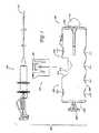
図1は、本発明のいくつかの特徴構造、態様、および利点に従って配置および構成される弁装填システム100の実施形態を例示する。例示された弁装填システム100は一般に、中でも配備カテーテル102、カートリッジ104、および弁装填具106を備える。カートリッジ104は、弁または他の医療器具を担持、輸送、および/または収納する。いくつかの構成では、カートリッジ104は、限定されたまたはより長時間の間、弁または他の医療器具を収納するように設計される。いくつかの実施形態では、カートリッジ104は、他のカートリッジと互換性がある。弁装填具は、カートリッジ104を収容する第1の開放空洞214を備えうる。カートリッジ104が空洞214の中に位置決めされ、かつ配備カテーテル102の遠位端112が連結口108の中に位置決めされると、弁または他の医療器具は、弁装填具106を使用して、カートリッジ104から配備カテーテル102の中へ移転されうる。したがって、例示された弁装填具106は、弁または他の医療器具を配備カテーテル102の中へ滅菌装填するように構成されうる。 FIG. 1 illustrates an embodiment of a
例示された弁装填具106は、外部筐体構造202を備える。いくつかの実施形態では、外部筐体構造202は、プラスチック、金属、または他の同様の材料から製作される。好ましくは、外部筐体構造202は、手の中で保持するようにサイズ決めされかつ構成される。いくつかの実施形態では、外部筐体構造202は、使用者の手中に容易に配置することを可能にする長さを有しうる。例えば、外部筐体構造202は、長さが5、6、7、または8インチでありうるが、それは使用者の手中に容易に収まることになろう。外部筐体構造202は、人間工学的特性を高め、かつ人間の手の中に容易に配置されるか、または人間の手によって容易に制御するために、一般に円筒形状または他の適切な形態を備えうる。例示された構成では、外部筐体構造202は、平坦化された円筒形状を備える。他の構造、材料、形状、およびサイズも可能である。 The illustrated
図1および図2に例示されたように、筐体構造202は、上部側204、下部側206、近位端208、および遠位端210を有しうる。本明細書で使用される任意の方向を表す用語は、単に基準の枠を提示するにすぎず、請求されている発明の範囲を限定するものと考えられるべきではない。本明細書で使用されている場合、「遠位」とは、弁または他の医療器具が中に配備されることになる箇所に向かうことを意味し、他方で「近位」とは、構成要素の使用者に向かう(例えば、弁装填具106の使用者に向かう)ことを意味する。 As illustrated in FIGS. 1 and 2, the
外部筐体構造202は、上部および下部側204、206に沿って複数の凹部212を特徴的に備えることが好ましい。例示された外部筐体構造202は、上部側204に沿って2つの凹部212を備え、下部側206に沿って4つの凹部212を備える。いくつかの実施形態では、上部側204に沿った2つの凹部212は、下部側206に沿った4つの凹部212中の2つと概ね位置合わせされる。好ましくは、2つの凹部212は、上部側204の対向端上に位置決めされる。より好ましくは、上部側204の2つの凹部212は、第1の開放空洞214の各側2つの凹部212の一方と位置決めされる。 The
第1の開放空洞214は、任意適切な構成を有しうる。いくつかの実施形態では、第1の開放空洞214は、角度付き部分216を有する実質的に長方形の形状を備える。しかし、他の形状および寸法が可能である。いくつかの実施形態では、第1の開放空洞214の形状および構成は、カートリッジ104が、唯一の方向、配向、または位置で第1の開放空洞214の中へ挿入されうるように、カートリッジ104の外部形状および構成に対応する。換言すれば、筐体202の空洞214は、第1の形状を有し、カートリッジ104は、筐体202の中へ挿入されるかまたはこの筐体と結合されるときに、カートリッジ104が、その意図された使用のために適正に配向されるように、相補的な形状を備えうる。 The first
図1および図2を参照すると、筐体構造202は、配備カテーテル102または別の器具、例えば、出荷錠止具114の遠位端112を受け入れうる第2の開放空洞218によって一部が画定される連結口108を備えうる。いくつかの実施形態では、出荷錠止具114の近位端は、配備カテーテル102の遠位端112の形状および構成に緊密に対応するように形作られかつ構成されうる。例示された筐体構造202は、配備カテーテル102の遠位端112を受け入れるのを助ける漏斗型構成を有する第2の開放空洞218を備えるが、筐体構造202は、一般に平坦な遠位端210または突出する遠位端210を備えうる。 With reference to FIGS. 1 and 2, the
弁装填具106の筐体構造202は、任意適切な様態で一体に固定される2つの半部分または側面202A、202Bから製作されうる。いくつかの構成では、2つの部分202A、202Bは、互いにスナップ嵌めして、支柱または同様物で一体に固定されうる。好ましくは、2つの部分の一方202Bが雄部分と考えられ、他方で2つの部分の他方202Aが雌部分と考えられて、雄および雌部分は、任意適切な様態で一体に接合されうる。 The
いくつかの実施形態では、かつ図3および図4に最も適切に示されるように、筐体構造202は、限定されるものではないが、装填具プランジャ220(本明細書ではアクチュエータとも呼ばれる)、カートリッジ錠止機構222、位置合わせ挿入具224、位置合わせ管226、ならびに第1および第2の把持爪228A、228Bを含む、複数の構成要素を収容する1つまたは複数の室を画定する。 In some embodiments, and as best shown in FIGS. 3 and 4, the
図4および5を参照すると、装填具プランジャまたはアクチュエータ220は、例示された筐体構造202の軸中心の内部におよびこの軸中心に沿って滑動するように構成される。いくつかの実施形態では、装填具プランジャまたはアクチュエータ220は、筐体構造202の軸中心の中へおよびこの軸中心に沿ってねじ込まれまたは回転されように構成される。いくつかの実施形態では、筐体構造202は、プランジャまたはアクチュエータ220が、弁または医療器具を配備カテーテルまたは配備装置の中へ完全に装填するために筐体中の正確な位置に移動し終えたときに、使用者に信号を送ったりまたは表示したりするために止めを備える。いくつかの実施形態では、カートリッジ104は、プランジャまたはアクチュエータ220が、弁または医療器具を配備カテーテルまたは配備装置の中へ完全に装填するために筐体中の正確な位置に移動し終えたときに、使用者に対して止めまたは信号もしくは表示として働く厚めのタブ431を有するカバー、キャップ、または蓋422を備える。いくつかの実施形態では、この厚めのタブ431は、プランジャまたはアクチュエータ220が、どれだけ遠くに筐体の中へ移動できるかを決め、それによって配備カテーテルまたは配備装置の内部における弁または医療器具の位置に影響を与えるように、長さ、形状、および/またはサイズを変更する。いくつかの実施形態では、カバー、キャップ、または蓋422は、カートリッジ104の外表面と面一に位置決めされうるか、またはカバー、キャップ、または蓋422は、プランジャまたはアクチュエータ220が、どれほど遠くに筐体の中へ移動できるかを決め、それによって配備カテーテルまたは配備装置の内部における弁または医療器具の位置に影響を与えるために、カートリッジ104の外表面から差し込まれて(異なる深さで)位置決めされうる。いくつかの実施形態では、カートリッジ104は、プランジャまたはアクチュエータ220が、弁または医療器具を配備カテーテルまたは配備装置の中へ完全に装填するために、筐体中の正確な位置に移動し終えたことを可聴的に示す歯または薄目のタブ430を有するカバー、キャップ、または蓋422を備える。図5に示されたように、装填具プランジャまたはアクチュエータ220は、装填具プランジャ220の少なくとも一部分に沿って延びる軸方向溝
230を有しうる。この軸方向溝230は、装填具プランジャ220の遠位端の近位で終わることが好ましい。軸方向溝230の遠位端は、この軸方向溝230を斜めに横切って延びる他の溝232(図4参照)の内部で終わることが好ましい。With reference to FIGS. 4 and 5, the loader plunger or
230. This
図4、5、および6に例示されるように、カートリッジ錠止機構222(本明細書では安全装置とも呼ばれる)は、筐体構造202の内部に位置決めされうる。例示されたカートリッジ錠止機構222は、第1の端部234および第2の端部を備える概「U字」形状をした構成または同様物を備える。例示されたカートリッジ錠止機構222の第1の端部234は、旋回ピン236によって支持されかつ/またはこのピンに結合されて、錠止機構222の均衡は、この旋回ピン回りに回転もしくは弧を描いて回転、または移動することが許容される。 As illustrated in FIGS. 4, 5, and 6, the cartridge locking mechanism 222 (also referred to herein as a safety device) can be positioned within the
図5および図9に示されるように、錠止機構222は、例示された構成では、例示された外部筐体202の雄の半部分202Aに面する第1のこぶ238および第2のこぶ240を備える。第1のこぶ238は、第2のこぶ240よりも僅かに大きく、第1のこぶ238は、概ね溝232の形状および配向に対応する形状および配向を有する。第1のこぶ238は、軸方向に軸方向溝230に沿って延びる表面の少なくとも1つを収容しうる距離だけ第2のこぶ240から分離される。さらには、第2のこぶ240は、この第2のこぶが軸方向溝230の内部に受け入れられうるようにサイズ決めされ、他方で第1のこぶ238は、この第1のこぶが、軸方向溝230の内部に受け入れられえないようにサイズ決めされる。 As shown in FIGS. 5 and 9, the
したがって、装填具プランジャ220が、筐体構造202の中へ押し込まれるとき、錠止機構222は、第2のこぶ240が、軸方向溝230と位置合わせされるまで、第1のこぶ238が、概ね斜めの溝232の内部で移動すると僅かに回転する。錠止機構222が回転し、かつ第2のこぶ240が、軸方向溝230と位置合わせされるとき、装填具プランジャ220を筐体構造202の中へさらに押し込むと、装填具プランジャ220を遠位に移動させて、第2のこぶ240が、軸方向に軸方向溝232に沿って移動する。この連続的な移動の間に、錠止機構は、第2のこぶ240が軸方向溝230内部に位置決めされることにより、回転に対抗して固定される。 Thus, when the
同様に、装填具プランジャが、筐体構造202から引き出されると、軸方向溝230は、第2のこぶ240が、斜めの溝232に達するまで、第2のこぶ240に対して移動する。第2のこぶ240が、斜めの溝232に達するとき、第2のこぶ240は、斜めの溝の内部で滑動し、それは錠止機構222を回転させる。錠止機構222の回転は、第1のこぶ238を斜めの溝232の中へ引き込む。第1のこぶ238は、この第1のこぶ238が、斜めの溝232の内部に位置決めされると、装填具プランジャ220を外部筐体構造202からさらに引き出すことを停止する。 Similarly, when the loader plunger is withdrawn from the
図8を参照すると、錠止機構222はまた、第1の止め242および第2の止め244を備える。錠止機構222の回転移動は、例示された構成では第1の止め242および第2の止め244によって限定される。第1の止め242は、第1の方向(すなわち、上向きまたは時計回り回転)における回転時に、筐体構造202の第1の表面246と当接し、第2の止め244は、第2の方向(すなわち、下向きまたは反時計回り回転)における回転時に、筐体構造202の第2の表面248と当接する。他の構成を使用しても、錠止機構222の回転移動範囲を限定することができる。 Referring to FIG. 8, the
以上に説明されたように、例示された錠止機構222はまた、第2の端部250を備える。この第2の端部は、第1の開放空洞214の中へ開く開口部252を貫通する。カートリッジ錠止機構222の第2の端部250は、カートリッジ104を筐体構造202の第1の開放空洞214中へ固定するか、またはカートリッジ104が、筐体構造202から装填具プランジャ220が完全に引っ込められることなく、第1の開放空洞214の中へ挿入される恐れを低減する腕、またはブラケット、または棒として働く。この様態では、錠止機構222は、プランジャ220が、第1の開放空洞214またはカートリッジ104から完全に引っ込められることなく、カートリッジ104の挿入または取出しによって引き起こされうる損傷からプランジャ220を保護する。錠止機構222が、筐体構造202の第1の開放空洞214に向かって回転、弧を描いて回転、または移動すると、第2の端部250の腕、ブラケット、または棒は、開口部252を通って筐体構造202の第1の開放空洞214中へ進入または移動する。カートリッジ104が、第1の開放空洞214の内部に存在する場合には、第2の端部250の腕、ブラケット、または棒は、カートリッジ104と係合しうるか、または別様にカートリッジ104を筐体構造202の中へ錠止しうる。装填具プランジャ220が筐体構造202から引き出されると、カートリッジ錠止機構222は、カートリッジ錠止機構222を筐体構造202の第1の開放空洞214から離れて回転、弧を描いて回転、または移動し、それによって第2の端部250の腕、ブラケット、または棒が、筐体構造202の第1の開放空洞214から抜き出されるかまたは実質的に抜き出されて、カートリッジが第1の開放空洞214の内部に存在する場合には、カートリッジ104を解錠または切り離すことを可能にする。 As explained above, the illustrated
図10および図11を参照すると、位置合わせ挿入具224が、概ね通路252を画定する。通路252の少なくとも一部分は、この部分の近位端からこの部分の遠位端にかけて直径が低減する。いくつかの実施形態では、この直径は、位置合わせ挿入具224の近位端から、途中まで位置合わせ挿入具224を通る箇所にかけて低減する。他の構成が可能である。 With reference to FIGS. 10 and 11, the
位置合わせ挿入具224の外部構造は、任意適切な構成を有しうるが、例示された構成は、概円筒形の近位端254およびより小さい直径の概円筒形の近位端256を備える。好ましくは、位置合わせ挿入具224の近位端254は、その近位端の表面が、第1の開放空洞214の周囲または隣接表面と概ね面一であるように配置される。 Although the external structure of the
位置合わせ挿入具224は、筐体構造202の中に位置決め可能であり、配備カテーテル102の中へ挿入または位置決めするために、弁または医療器具704を案内しかつ/または圧縮された状態に圧縮するように構成されうる。位置合わせ挿入具224は、プラスチック、金属、または他の同様の材料から製作されうる。例示された構成では、近位端254は、2つ以上のタブ258を含む。これらのタブ258は、外部筐体202の中に形成された凹部の中に位置決めされうる。したがって、これらのタブ258は、位置合わせ挿入具224を外部筐体202の内部に適正に配置し、かつ位置合わせ挿入具224が、外部筐体202に対して軸方向移動することを限定するのを助ける。 The
位置合わせ挿入具224によって画定された通路252は、位置合わせ管226によって画定された通路260と軸方向に位置合わせされることが好ましい。通路260は、近位の概円筒形部分262、先細り部分または漏斗形状導路264、より小さい直径の概円筒形部分266、別の僅かにより大きい直径の概円筒形部分268、および僅かに拡大する部分270を備える。この通路は、概円筒形遠位部分272および構成が、概円錐形である遠位部分274をさらに備える。 The
より小さい直径部分266は、装填具106が共に使用されるように設計されるカテーテルの外径よりも小さいことが好ましく、他方で僅かに大きい直径部分268は、同じ外径よりも僅かに大きい。したがって、挿入時に、配備カテーテル102の遠位端は、これら2つの部分266、268の間に画定された段に当接しうる。 The smaller diameter portion 266 is preferably smaller than the outer diameter of the catheter designed for use with the
位置合わせ管226の概円筒形近位部分262は、位置合わせ挿入具224の遠位端256を受け入れるようにサイズ決めされかつ構成されることが好ましい。図示されたように、位置合わせ挿入具224の近位端254の遠位に面する表面は、浅い導路276を備えることが可能であり、位置合わせ管226の近位端の近位に面する表面には、多少より深い導路278が設けられうる。 The generally cylindrical proximal portion 262 of the
ばね280または同様物が、位置合わせ挿入具224の浅い導路276内部の近位端内部に、かつ位置合わせ管226のより深い導管278の内部の遠位端内部に位置決めされうる。ばね280または他の偏倚部材は、位置合わせ挿入具224および位置合わせ管226を隔てるように有利に偏倚する。位置合わせ挿入具224は、タブ258によって外部筐体202に対して概ね軸方向に固定されるので、位置合わせ管226は、外部筐体202に対して軸方向移動可能であり、ばね280によって、外部筐体202の周囲部分の特徴構造によって画定されうる第1の位置に向かって偏倚されうる。 A
位置合わせ管226は、プラスチック、金属、または他の同様の材料によって製作されうる。いくつかの実施形態では、位置合わせ管226は、概長方形の外部形状を有する(しかし、他の形状および構成が、本実施形態の趣旨から逸脱することなく可能である)。 The
位置合わせ管226は、好ましくは開口部282を有する。例示された開口部282は、概ね垂直である。好ましくは、開口部282は、例示された位置合わせ管226の中心部分を貫通する。開口部282は、開口部282の両側に1つずつ第1の把持爪228Aおよび第2の把持爪228Bを受け入れるように構成される。いくつかの実施形態では、開口部282は、長方形の形状を有するが、他の形状および構成も同様に可能である。位置合わせ管226はまた、第1および第2の外部支柱284を好ましくは備える。支柱284は、位置合わせ管226の横表面から横向きに外側に延びる。好ましくは、支柱284の位置は、支柱284の軸方向箇所が、開口部282の近位端と遠位端との間にあるように、開口部282の各横側に対して存在する。他の構成が可能である。 The
第1および第2の把持爪228A、228Bは、好ましくはプラスチック、ゴム、高分子、または他の同様の材料から製作される。第1の把持爪228Aは、一般に位置合わせ管226の上方に位置決め可能であり、他方で第2の把持爪228Bは、一般に位置合わせ管226の下方に位置決め可能である。把持爪228A、228Bはそれぞれが、筐体構造202に連結されるそれぞれの旋回ピン288A、288Bを支持され、かつ/またはこれらのピンに結合される第1の端部286A、286Bを備えうる。したがって、把持爪228A、228Bは、旋回ピン288A、288B回りに弧を描いての回転または回転が許容される。把持爪228A、228Bはそれぞれが、第2の端部290A、290Bも有しうる。 The first and second gripping claws 228A, 228B are preferably made from plastic, rubber, polymer, or other similar material. The first gripping claw 228A can generally be positioned above the
例示された構成における各第2の端部290A、290Bは、把持部分292A、292Bおよび包囲部分294A、294Bを備える。把持部分292A、292Bは、少なくとも一部が、位置合わせ管226中の開口部282の中へ挿入されるように構成可能であり、包囲部分294A、294Bは、少なくとも一部が位置合わせ管226の外表面の周囲で包まれるように構成可能である。より好ましくは、包囲部分294A、294Bは、位置合わせ管226の支柱284に当接する。さらにより好ましくは、包囲部分294A、294Bの中に形成された取付け凹部296A、296Bが、位置合わせ管226の支柱284に当接し、取付け凹部296A、296Bは、ピン288A、288Bによって画定された回転軸に対して遠位方向にずれされる。ピン288A、288Bによって画定された回転軸に対する凹部296A、296Bの箇所における僅かなずれは、位置合わせ管226が、近位方向における僅かないかなる変位にも追従して、第1の位置にスナップ嵌めさせる。 Each
初期設定または通常位置では、把持爪228A、228Bは、位置合わせ管226に実質的に直交しうる。第1および第2の把持爪228A、228Bの第2の端部290A、290Bが、位置合わせ管226の中に位置決めされると、一体になって、配備カテーテル102を位置合わせ管226の内部に維持、固締、保持、錠止、および/または把持するように構成される、概円筒形もしくは管状区域または固締具を形成する第1の把持部分300Aおよび第2の把持部分300Bが存在する。 In the default or normal position, the gripping claws 228A, 228B can be substantially orthogonal to the
第1および第2の把持部分300A、300Bは、尖頭、鋭い特徴構造、または畝302を備える。図示されたように、畝302は、近位および遠位端により大きな内径を画定し、中間により小さい内径を画定するように好ましく構成される。したがって、把持爪228A、228Bが近位方向に回転すると、相互に概直角である畝によって画定された直径は、把持爪228A、228Bが、出発位置(すなわち、位置合わせ管226の第1の位置に対応する)に向かって戻り回転するとき、中間で相互に概直角である畝によって画定された直径よりも大きい。したがって、出発位置では、畝302の中心畝は、配備カテーテルの端部を保持するように協働し、他方で、一旦出発位置から近位方向に回転されると、より大きな畝は、互いに協働して、配備カテーテルが、把持爪228A、228Bに挿入されるか、またはこれらの把持爪から取り外されうるように、より大きな直径を画定する。 The first and second
いくつかの構成では、1つまたは複数の把持爪228A、228Bが解除機構304の少なくとも一部に当接する。例示された解除機構304は、リーフばね306を備える。リーフばねの第1の部分308が、旋回ピン310によって支持されかつ/またはこのピンに結合され、リーフばね306は、少なくとも一部が旋回ピン310回りに回転することを可能にする。リーフばね306の第1の部分308は、ボタン314と係合されうる片持ちレバー部分312を備える。リーフばね306は、外部筐体202、位置合わせ管226、または同様物の内部構造の上に少なくとも一部が休止するように構成されうる第2の部分316を備える。第1の部分308および第2の部分316は、近位端で接合可能であり、相互に対してある角度を成して延びうる。さらには、第1の部分308は、第2の部分316よりも好ましくはより剛性である(例えば、曲げに抵抗するためにより大きな厚さを有する)。第1の部分308が旋回ピン310回りに回転すると、第2の部分316が、旋回ピン310回りにおける第1の部分308の回転に抵抗する役目をするように、第2の部分316の撓みを引き起こす。より好ましくは、片持ちレバー部分312が、ボタン314によって例示された構成で下向きに移動される場合に、第2の部分316は、第1の部分308を出発位置に偏倚する。 In some configurations, one or more gripping claws 228A, 228B abut at least a portion of the
図10および11に例示されたように、いくつかの実施形態では、リーフばね306は、把持爪228Aと係合されるカム部分318を備える。いくつかの実施形態では、把持爪228A、228Bは、カム部分318が、把持爪228Aの側部に沿って上向きに十分な距離を滑動するときに、リーフばね306のカム部分318によって係合されうる棚部、唇部、溝、または空洞320を備える。したがって、把持爪228Aのカム部分318は、近位に誘導された力が、位置合わせ管226に与えられるまで、撓んだ位置の中へ錠止されうる。リーフばね308は、把持爪228Aの棚部上の定位置へスナップ嵌めするときに、明確なクリック音または他の可聴音を立てうる。 As illustrated in FIGS. 10 and 11, in some embodiments, the
以上に論じられたように、ボタン314が、筐体構造202の中へ押し入れられるときに、ボタン314は、片持ちレバー部分312に対して力を印加し、それによってリーフばね306を旋回ピン310回りに回転、旋回、または弧を描いて回転させる。リーフばね306の片持ちレバー部分312、したがって第1の部分308が移動すると、カム部分318を回転させるが、それは、カム部分318を把持爪228Aの一部に沿って効果的に滑動させて、把持爪228Aに沿って定位置へスナップ嵌めさせる。カム部分318と把持爪228Aとの間の相互作用は、把持爪228Aを旋回ピン310から離れるように回転させる。把持爪228Aが移動すると、取付け凹部296A、296Bと支柱284との間の境界面により、位置合わせ管226を近位方向に移動させる。位置合わせ管226が移動すると、把持爪228A、228Bの両方の回転をもたらし、位置合わせ管226の内部で先に固定された任意のカテーテルに対する把持は、カテーテルが取り出されうるように解除される。 As discussed above, when the
好ましくは、カム部分318は、引き続くカテーテルの挿入が行われるまで、把持爪228Aの表面と接触状態に留まる。例示された実施形態では、カム部分318が上に休止する僅かな段320が設けられる。カム部分318が、段320の縁伝いに移動すると、取外しのためにカテーテルの分離を示す音をもたらす。カテーテルの引き続く挿入は、位置合わせ管226をさらに近位方向に駆動するが、それは、リーフばねのカム部分318が、段320から外れて、カテーテルの固締が行われたことを示す付随音と共に、このカム部分の元の位置に戻ってスナップ嵌めすることを可能にする。 Preferably,
ボタン314は、プラスチック、金属、または他の適切な材料から作製可能であり、ボタン314は、筐体構造202の内部に移動可能に位置決めされうる。いくつかの実施形態では、ボタン314は、このボタン314を筐体構造202の上側204の外側表面に向かって押すために力を印加するばねまたは偏倚要素322に結合されるか、連結されるか、またはこの要素によって係合される(それは、ボタン314の通常の位置である)。ボタン314は、このボタン314が、ばねまたは偏倚要素322によって筐体構造202から完全に押し出されるのを防止するように構成されうる唇部または棚部324を備える。ばねまたは偏倚要素322は、ボタン314の心棒323伝いに取り付けられうる。ボタン314が、筐体構造202の中へ押し込まれるとき、ボタン314は、ばね322が圧縮される第2の位置に向かって移動する。この第2の位置では、ボタン314は、リーフばね306の片持ちレバー312に係合しかつ/またはこのレバーに対して力を印加し、それによって、配備カテーテル102を解放するために、リーフばね306のカム部分318を第1の把持爪228Aに係合させる。いくつかの実施形態では、ボタン314は、リーフばね306の片持ちレバー312に係合しかつ/またはこのレバーに対して力を印加し、それによって、リーフばね306のカム部分318を第1の把持爪228Aに係合させて第1の把持爪228Aを近位端に向かって移動または回転させ、それによって配備カテーテル102を解放させる。いくつかの実施形態では、第1および第2の把持爪228A、228Bは結合され(例えば、これらの把持爪が位置合わせ管226に連結されることにより)、したがって、第1の把持爪228Aが、リーフばね306によって近位端に向かって移動または回転されるときに、第1および第2の把持爪228A、228Bは、共に協調して近位端に向かって移動または回転し、それによってこれらの把持爪は、配備カテーテル102に対する把持を解除する。 The
いくつかの実施形態では、ボタン314はまた、図10および11に例示されたように、安全滑動機構326に結合されかつ/または係合される。安全滑動機構326は、ボタン314が筐体構造202の中へ押し込まれる恐れを低減または排除するように構成されうる(このような移動が所望されなければ)。安全滑動機構326は、プラスチック、金属、または他の同様の材料から製作されうる。安全滑動機構326は、近位端328および遠位端330を備える。いくつかの実施形態では、近位端328は、ボタン314の唇部または棚部324に係合するかまたは受け入れるように構成されうる、空洞または溝332を備える。換言すれば、滑動機構が近位位置にあるときに、ボタン314のへり、畝、唇部、または棚部324は、滑動機構326の空洞または溝332の内部に位置決めされ、したがって、滑動機構326は、ボタン314の意図しない押下の恐れを低減する。 In some embodiments, the
安全滑動機構326の遠位端330は、ボタン314の唇部または棚部324を安全滑動機構326の空洞または溝332と係合させるために、安全滑動機構326をボタン314に向かって押すための力を印加する、ばねまたは他の偏倚要素336に結合、連結、接触、または係合される。いくつかの構成では、安全滑動機構326は、ばねまたは他の偏倚要素336の少なくとも一部を受け入れる凹部を備える。安全滑動機構が、第2の位置に向かって遠位に移動または滑動されるとき、安全滑動機構326は、ボタン314を解放し、切り離し、かつ/またはボタン314が筐体構造202の中へ押し込まれることを可能にする。 The
したがって、配備カテーテル102の遠位端を位置合わせ管から取り外すかまたは解除するかまたは解放するために、2段解除過程が、いくつかの実施形態で使用される。配備カテーテル102を解除するために、使用者は最初に安全滑動機構326を遠位端に向かって滑動させ、次いで使用者は、配備カテーテル102を筐体構造202から解除しかつ引き抜くために、ボタン314を筐体構造202の中へ押し込む。2段解除過程は、配備カテーテル102が破損する可能性を低減または排除し、他方で弁704を配備カテーテル102の中へ位置決めする。さらには、2段解除過程は、弁704が、配備カテーテル102の内部に適正に位置決めされ終える前に、配備カテーテル102が取り外される可能性を低減または排除する。 Thus, a two-stage release process is used in some embodiments to remove, release or release the distal end of the
カートリッジ
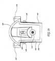
カートリッジ104は、任意適切なサイズ、形状、または構成を有しうる。例示された実施形態では、カートリッジ104は、第1の開放空洞214の内部に受け入れられるように、サイズ決めされ、形作られ、かつ構成される。より好ましくは、カートリッジ104は、唯一の配向のみで、第1の開放空洞214の内部に受け入れられるようにサイズ決めされ、形作られ、かつ構成される。Cartridge The
図12〜21に示されるように、例示されたカートリッジ104は、一般に近位壁400および遠位壁402を備える。第1の側壁404および第2の側壁406は、全体的に近位壁400と遠位壁402との間に延びる。また例示されたカートリッジは、美的理由のために、弁装填具106の外部筐体202に合わせて形状および構成が相関しうる(例えば、嵌合形状)上部壁408を備える。「壁」という用語は、任意の単一の表面または部材を意味するように狭義に理解されるべきではなく、むしろ広義に理解されるべきであり、壁とは、単一の平面内にあるのではなく、互いに協働して全体的な境界を形成する多表面から成りうる。したがって、例示されたカートリッジ104は、丸味を帯びた上部壁を有する概長方形の箱形状を備える。他の構成および形状、例えば、円形、円筒正方形、三角形、円錐形、台形、楕円形、またはこれらの組合せも可能である。 As shown in FIGS. 12-21, the illustrated
カートリッジ104は、任意適切な様態でかつ任意適切な材料から形成されうる。いくつかの実施形態では、カートリッジ104の大部分は、プラスチックもしくは金属または別の適切な材料から成形される。 The
カートリッジ104は、好ましくは近位から遠位方向に延びる少なくとも1つの通路410を画定する。いくつかの実施形態では、通路410は、近位壁400から遠位壁402に延びる。好ましくは、通路410は、近位から遠位にかけて先細る第1の先細り部分または先細にされた内腔412と、概円筒形部分414と、近位から遠位にかけて同様に先細る第2の先細り部分416とを備える。したがって、通路410は、近位開口部418から遠位開口部420まで延びて、近位開口部418は、遠位開口部420よりも大きい。他の構成が可能であるが、通路410は、一般に近位開口部418から遠位開口部420にかけて直径が低減することが好ましい。 The
近位開口部418は、一般にカバー、キャップ、または蓋422を使用して閉鎖可能であることが好ましい。カバー422が図14に示されており、図15では除去されて示されている。カバー422は、任意適切な構成を有しうる。例示された実施形態では、カバー422は、一般に透明または半透明であり、プラスチック材料から形成される。例示されたカバー422は、カートリッジ104上の定位置へスナップ嵌めするが、他の構成が可能である。例示されたカバー422は、カートリッジ104内部に形成された対応する開口部の中へスナップ嵌めする2本の下部脚424および1本の上部脚426を備える。
カバー422は、好ましくは開口部428を画定する。開口部428は、任意適切なサイズおよび構成を有しうる。例示された実施形態では、開口部428のサイズおよび形状は、プランジャ220の断面形状に概ね相関する。さらには、歯または薄目のタブ430が、例示された開口部428の中へ上向きに延びる。歯430は、好ましくは撓みうる。プランジャ220は、使用時に開口部428の内部に受け入れられ、歯430は、プランジャ上に形成された畝伝いの定位置へスナップ嵌めする。したがって、歯430は、プランジャ220が完全に押下される時点を示す働きをし、また歯430は、プランジャ220を近位方向に引っ込めるのに十分な力によって作用を受けるまで、プランジャ220の完全に押下された位置を維持する。 Cover 422 preferably defines an
少なくとも1つの通路410が、弁または他の医療器具500を受け入れかつ収納するように好ましく構成される。カバー422は、弁または医療器具500が、カートリッジ104から取り出される恐れを低減または排除するように構成され、他方で弁または医療器具500は、カートリッジ104の中に収納されることが意図されている。図示されたように、医療器具500は、多繋止具502を備えうる。繋止具502は、直径を画定する。好ましくは、カバー422と第1の先細り部分412との間の近位開口部418が、繋止具502によって画定された直径よりも大きい外径と、繋止具502によって画定された直径よりも僅かに小さい内径とを有する端繰り432を備える。したがって、繋止具502は、端繰り432の遠位壁とカバー422との間に捕捉されうる。 At least one
いくつかの実施形態では、通路410は、同じかまたは異なるサイズ、形状、または種類である2つ以上の弁または医療器具500を受け入れかつ/または収納するように構成しうる。好ましくは、異なるカートリッジ104は、異なるサイズの弁または医療器具500が、カートリッジ104の内部に収納されていることを示す異なる色、象徴、数字、および/または固有の識別子を備える。いくつかの構成では、カートリッジ104は、他の識別索引(例えば、数字、色、文字、模様など)を使用して、異なる製薬、被膜、または同様物が使用されているかどうかを含めて、異なる医療器具を示すことができる。 In some embodiments, the
いくつかの実施形態では、カートリッジ104は、多数の弁または医療器具500を収納するための多通路410または室を備えることが可能であり、多中空中心または室は、デイジーホイールまたは他の回転子が、配備カテーテル102の中へ多数の弁500が装填されることを可能にするように、使用者によって回転または別様に移動されうる(例えば、持上げまたは降下)ようにカートリッジ104内部でデイジーホイールまたは他の回転子に結合されうる。 In some embodiments, the
カートリッジ104はまた、好ましくは少なくとも1つの解放タブ434を含む。解放タブ434は、カートリッジの基部に接合されて、カートリッジ104と一体形成される。例示された実施形態では、2つの横面のそれぞれが、解放タブ434を有する。各解放タブ434の端部は、指パッド436および、指パッド436の直下に錠止突起438を備える。錠止突起438は、カートリッジ104を筐体構造202の第1の開放空洞214中へ錠止するために、弁装填具106上の対応する構造に係合する。2つの解放タブ434の指パッド436が、相互に向かって押し込まれるとき、錠止突起438は、筐体202の構造から分離し、カートリッジ104は、筐体構造202の第1の開放空洞214から解除される。1つの実施形態では、解放タブ434は、カートリッジ104と一体形成され、プラスチック、高分子、または他の適切な材料から製作される。他の錠止構成も使用されうる。 The
カートリッジ104の近位壁400は、カートリッジ錠止機構222の第2の端部250の腕、ブラケット、または棒を受け入れる少なくとも1つの溝領域または凹部440を備えうる。したがって、第2の端部250が、第1の開放空洞214の中へ延びるときに、第2の端部250は、カートリッジ104の溝領域440と係合する。 The
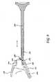
配備カテーテル
任意の種類の配備カテーテル102が、弁装填具106に使用可能であり、例示された配備カテーテル102の以下の説明は、一般に例示にすぎず、限定的ではないことが意図されているということが理解されよう。Any type of
図22を参照すると、配備カテーテル102は、近位端700および遠位端702を有する。制御部分704は近位端700に配置され、送達部分706は遠位端702に配置される。 Referring to FIG. 22, the
図22〜25を参照すると、カテーテル心棒710は、近位端から遠位端まで延びる。カテーテル心棒710は、気管支鏡の中にまたは体内に挿入されるように構成される。好ましくは、カテーテル心棒710は、内腔712および遠位配置された空洞714を備える。内腔712は、空洞714と連通している遠位端を有しうる。いくつかの実施形態では、カテーテル心棒710の内腔712は、被膜(例えば、テフロン(登録商標))または裏打ち(例えば、ポリテトラフルオロエチレン(PTFE)ライナ)、もしくはこれら2つの何らかの組合せを有しうる。他の構成が可能である。 22-25, the
カテーテル心棒710は、プラスチック、金属、高分子、ゴム、ナイロン、他の柔軟性材料、またはこれらの組合せから製作されうる。いくつかの実施形態では、カテーテル心棒710は、柔軟性の高分子押出成形品、例えば、Pebaxまたはナイロンから製作される。いくつかの実施形態では、カテーテル心棒710は、異なるデュロメータ硬度水準を含む異なる領域を有しうる。例えば、カテーテル心棒710の近位端の大部分は、伸びを防止するより硬いデュロメータ硬度を有しうる一方で、カテーテル心棒710の遠位端は、柔軟性を増すためにより軟らかいデュロメータ硬度を有しうる。いくつかの実施形態では、カテーテル心棒710は、様々な充填剤または成分、例えば、色には着色剤、放射線不透過材料には硫酸バリウム、および潤滑性にはテフロンを含みうる。 The
カテーテル心棒710の遠位端は、カテーテル先端716を備えうる。いくつかの実施形態では、カテーテル先端716は、遠位端702の最遠位部分に配置されうる。カテーテル先端716は、弁500が、カテーテル心棒710から体内へ配備または移植されうるように、弁500に対して引っ込め可能であるカテーテル鞘718の少なくとも一部を画定しうる。 The distal end of the
いくつかの実施形態では、カテーテル鞘718の少なくとも一部は、透明または半透明の材料を含む。カテーテル鞘718および/またはカテーテル先端716は、弁500の適正な配置を確証するために、弁ラインを備えうる(いくつかの実施形態では、弁ラインは、カテーテル鞘718の中に埋め込まれた黄色い顔料を含む)。弁ラインは、弁500が体内に配備する場所を示す。 In some embodiments, at least a portion of the catheter sheath 718 includes a transparent or translucent material. The catheter sheath 718 and / or the catheter tip 716 can be provided with a valve line to ensure proper placement of the valve 500 (in some embodiments, the valve line is a yellow color embedded in the catheter sheath 718). Including pigments). The valve line indicates where the
カテーテル先端716は、金属先端および/またはプラスチック先端(例えば、同種組織移植片または他のウレタン)もしくは装填時に把持爪228A、228Bが配備カテーテル102を把持することを可能にする他の適切な構造を好ましくは含む。いくつかの実施形態では、プラスチックおよび/または金属先端716は、配備カテーテル102の遠位端に接合されるか、この遠位端に接着されるか、かつ/またはこの遠位端の中に埋め込まれる。 The catheter tip 716 may be a metal tip and / or a plastic tip (e.g., allograft or other urethane) or other suitable structure that allows the gripping claws 228A, 228B to grip the deployed
いくつかの実施形態では、先端718の内表面は、弁装着および配備時に摩擦を低減するために、ポリウレタン粘着防止被膜が被覆されうる。いくつかの実施形態では、先端716または配備カテーテル102の内表面は、被膜を有しない。その代わりに、先端716または配備カテーテル102の内表面は、配備カテーテル102と弁500との間の摩擦を低減するために、配備カテーテル102の端部の一部上に、かつ/または先端718および/もしくは先端716の内表面上に、限定するものではないが、弁500上の任意の膜材料を含めて、ポリテトラフルオロエチレン(PTFE)ライナを含みうる。いくつかの実施形態では、PTFEライナは、より堅牢な被膜(例えば、摩擦低減被膜)でありうる。 In some embodiments, the inner surface of the tip 718 can be coated with a polyurethane anti-stick coating to reduce friction during valve mounting and deployment. In some embodiments, the tip 716 or the inner surface of the
いくつかの実施形態では、PTFEライナは、弁500に接触する配備カテーテル102の内径上が滑らかであることが可能であり、外部突起とより適切に接着するように粗面を設けるために、配備カテーテル102の外径上に化学エッチングされうる。PTFEライナは、非常に薄くてよい(例えば、壁厚が約0.001インチから0.002インチ)。いくつかの実施形態では、次いでライナは、熱処理および犠牲押出成形品(例えば、フッ化エチレン-プロピレン樹脂(FEP)またはオレフィン)を使用して、外部カテーテル押出成形品の上に、または外部カテーテル押出成形品の外側にリフローイングされうる。この処理は、ライナを押出成形品に接着するために同時に熱を加え、他方で犠牲押出成形品(FEPまたはオレフィン)は、直径を圧縮して2つの材料を一体に溶融するために力を加えることができる。 In some embodiments, the PTFE liner can be smooth on the inner diameter of the
いくつかの実施形態では、配備カテーテル102は、この配備カテーテルの外部上に配備案内を備えうる。配備案内は、配備カテーテル102の遠位端に位置決めされるかまたは埋め込まれうる。配備案内は、患者および/または気管支鏡を透過して視認可能である放射線不透過性材料を含みうる。配備案内の可視性質は、使用者が弁を目標箇所に正確に位置決めすることを可能にする。 In some embodiments, the
図25を参照すると、カテーテル心棒空洞714の近位端は、安定化ワイヤ722用の先端720を含む。安定化ワイヤ先端720は、2つの構成要素が、好ましくはカテーテル心棒710に対して軸方向に一体に移動するように、安定化ワイヤ724に連結または結合される。先端720は、任意適切な構成を有しうるが、好ましくは遠位端中に凹部724を好ましく備える。凹部724は、配備時に弁500に対する制御を高めるために使用されうる。 Referring to FIG. 25, the proximal end of the catheter mandrel cavity 714 includes a
安定化ワイヤ722は、カテーテル心棒710中の内腔712または通路を貫通する。以上で説明されたように、カテーテル心棒710の内腔712は、安定化ワイヤ724が、カテーテル心棒710内部でより容易に移動することを可能にするために被覆されうる。安定化ワイヤ722は、カテーテル心棒710に対して軸方向移動することになる。したがって、安定化ワイヤ722は、カテーテル心棒710の内部で滑動可能でありうるか、このカテーテル心棒を通って移動されうるか、またはその内部で前送りされうる。安定化ワイヤ722は、カテーテル心棒710が、気管支鏡または体内通路を容易に横断することを可能にするために、ステンレス鋼ワイヤ上のテフロン被覆ステンレス鋼コイルでありうる。
いくつかの実施形態では、カテーテル心棒710の近位端に、カテーテル心棒710の内部上にPTFEライナを含む強化心棒部分が存在しうる。カテーテル心棒710の近位端にあるライナは、カテーテル心棒710の遠位端におけるよりも一般に厚いことが好ましい。より厚いライナは、押込み性を向上させるが、強化部分の屈曲性を低下させ、したがって遠位端のより薄いライナは、カテーテル心棒710が、近位端よりもきつい半径で曲がることを可能とする。 In some embodiments, there may be a reinforced mandrel portion at the proximal end of the
いくつかの実施形態では、カテーテル心棒710の近位端は、PTFEライナと、例えば、Pebaxまたはナイロンを含む高分子押出成形品との間に置かれる編組を備える。いくつかの実施形態では、編組は、伸張、座屈、および/または縺れに対する抵抗を与え、他方で弁または医療器具500を所望の箇所に送達する。編組は、剛性を低減し、それによってカテーテル心棒710の柔軟性を増大するために、好ましくは内径により近接して配置される。編組は、高分子(例えば、透明であり、MRI用途に使用されうるナイロン)、平坦ワイヤ(例えば、0.001インチ×0.005インチ)、または他の同様の材料を含みうる。いくつかの実施形態では、編組は、60ピクス/インチ構成を備えるが、ここでピクスとは、1インチ中の開放空間の数を指す。 In some embodiments, the proximal end of the
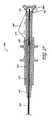
図26および図27を参照すると、安定化ワイヤ722(その遠位端が安定化ワイヤ先端724に連結される)は、制御部分704のキャップ726まで近位に伸びる。これをより適切に例示するために、安定化ワイヤ722は、制御部分704の近位端(すなわち、キャップ726)において、かつ制御部分704の遠位端において識別されている。安定化ワイヤ722の近位端は、任意適切な様態でキャップ726に連結されうる。いくつかの場合では、安定化ワイヤ722およびキャップ726は、圧入、切着剤による接着、接着、粘着、共成形または同様にされる。 Referring to FIGS. 26 and 27, the stabilization wire 722 (whose distal end is coupled to the stabilization wire tip 724) extends proximally to the
安定化ワイヤ722は、その近位端が伸縮式ハイポチューブ728を貫通する。ハイポチューブ728は、安定化ワイヤ722の一部を密閉する。したがって、ハイポチューブ728は、安定化ワイヤ722に横方向の支持を与えることを可能にし、かつ安定化ワイヤ722が、ハイポチューブ728の領域内における座屈、屈曲、または過剰変形の恐れを低減するのを助けうる。ハイポチューブ728は、好ましくは近位端がキャップ726に連結し、その遠位端が鞘保持具730の近位端上で当接する。 Stabilizing
ハイポチューブ728の遠位端は、鞘保持具730の内部に重ね収納される。好ましくは、ハイポチューブ728は、鞘保持具730の内部で軸方向に移動可能である。したがって、この様態では、ハイポチューブ728は、鞘保持具730に対して伸縮式である。鞘保持具730は、ハイポチューブ728の遠位に延びて、カテーテル心棒710の近位端上方に延びる。好ましくは、カテーテル心棒710の近位端は、鞘保持具730の中心部分の中へ延びる。より好ましくは、カテーテル心棒710および鞘保持具730は、軸方向移動するために一体に接合される。任意適切な連結が使用されうる。 The distal end of the
スリーブ滑動子筐体732の近位端が、キャップ726の中へスナップ嵌めし、他方でスリーブ滑動筐体732の遠位端が、鞘保持具730を密閉する。他の連結を使用して、スリーブ滑動子筐体732およびキャップ726を接合することも可能である。しかし、スナップ嵌めは、構造および製造を簡素化する。 The proximal end of the
スリーブ滑動子筐体732の遠位端は、カテーテル心棒710の近位部分に向かって先細る。スリーブ滑動子筐体732は、相対軸方向移動が、鞘保持具730とスリーブ滑動子筐体732との間に行われることを可能にする。換言すれば、スリーブ滑動子筐体732は、鞘保持具730が、弁500を配備する間に、スリーブ滑動子筐体732に対して近位に滑動することを可能にするように設計される。この相対近位移動は、鞘保持具730に連結されるカテーテル心棒710と、キャップ726に相互連結することによってスリーブ滑動子筐体732に連結される安定化ワイヤ722との間の相対移動をもたらす。 The distal end of the
好ましくは、スリーブ滑動子筐体732は、拡大された溝穴または窓734を備える。図28に示されるように、溝穴または窓734は、鞘保持具730の2本の指736を収容する。指736は、スリーブ滑動子740の中に形成された溝穴738と係合する。したがって、スリーブ滑動子740は、軸方向移動するために鞘保持具730と接合され、鞘保持具730を介してカテーテル心棒710に接合する。したがって、スリーブ滑動子740の任意の近位方向軸方向移動は、スリーブ滑動子筐体732および装着された安定化ワイヤ722に対する、カテーテル心棒710の対応する近位に誘導された軸方向移動を引き起こすことになる。換言すれば、外部スリーブ滑動子740が、キャップ726およびスリーブ滑動子筐体732に対して移動すると、カテーテル心棒710が、安定化ワイヤ722に対して移動することになる。 Preferably, the
歪み解放管742が、カテーテル心棒710の少なくとも近位部分を密閉する。歪み解放管742は、制御部分704からカテーテル心棒710の遠位端の多少近位にある箇所まで遠位に延びうる。いくつかの構成では、歪み解放管742は、カテーテル心棒710と、スリーブ滑動子筐体732(この筐体に対してカテーテル心棒710が移動する)の中の通路との間に延びる。したがって、カテーテル心棒710は、いくつかの構成では、歪み解放管742に対して軸方向移動することができる。任意適切な材料が、歪み解放管742を形成することができる。 A
制御部分704は、プラスチック、金属、または他の適切な材料から製作されうる。好ましくは、スリーブ滑動子740は、プラスチック成形部品である。したがって、指保持部を画定する畝744の形成は、比較的に経済的かつ簡素でありうる。他の構成も可能である。 The
以上で説明されたように、スリーブ滑動子740がキャップ726に向かって移動すると、カテーテル心棒710を安定化ワイヤ720に対して引っ込めることによって配備移動を引き起こすが、それは、弁500をカテーテル心棒710のカテーテル先端716から押し出す。したがって、いくつかの実施形態では、弁500が、カテーテル先端716から偶発的に配備される恐れを低減または排除しうる錠止特徴構造746が所望される。 As explained above, movement of the
例示された錠止特徴構造746は、キャップ726とスリーブ滑動子740との間に延びる少なくとも1つの部材を備える。少なくともこれら2つの構成要素間に延びることによって、錠止特徴構造746は、カテーテル心棒710と安定化ワイヤ720との間の偶発的な相対移動の恐れを低減しうる。当然のことであるが、他の態様では、カテーテル心棒710および安定化ワイヤに直接的にまたは間接的に連結することによって、カテーテル心棒710と安定化ワイヤ720との間に別の錠止特徴構造を構成することが可能である。 The illustrated
図26を参照すると、錠止特徴構造746は、くびき形状の錠止レバー748を備える。このレバー748は、部分カラー752で連結し合う2本の脚750を備える。これらの脚750はそれぞれが、スリーブ滑動子740中の開口部の中へスナップ嵌めするペグ750を備える。これらのペグ750は、脚750が、したがって、全体としてレバー748が、スリーブ滑動子740に対して旋回できるように、スリーブ滑動子740に対して旋回しうる。 Referring to FIG. 26, the
以上で論じられたように、レバー748は、部分カラー752を備える。この部分カラーは、キャップ726の下方部分周りにほぼ中途まで延びうる。キャップ726が取り囲まれる範囲は、用途に応じて変わりうるが、部分カラー752は、キャップ726周りに180度を僅かに超えて延びることが好ましい。他の構成が可能である。 As discussed above, the
脚750は、部分カラー752に対向する方向にお辞儀をする。脚750のこのお辞儀は、使用者による容易な片手操作を可能とする。換言すれば、お辞儀をした脚750は、一対の操作箇所754を創出するが、これらは、カラー752をキャップ726から容易に切り離すことを促進するために、大きなパッドでさらに機能が高められる。一旦カラー752がキャップ726から切り離されると、レバー748は、邪魔にならないようにどけられて、スリーブ滑動子740は、弁500が配備されうるように、キャップ726に向かって上向きに引っ張られる。 The
図1を再び参照すると、出荷錠止具114は、いくつかの実施形態では概円筒形の管であり、内腔を備えうる。出荷錠止具114は、一般に配備カテーテル102のカテーテル心棒710の形状および寸法と同様のものを備えうる。出荷錠止具114は、弁装填具106が、出荷されているか、または将来の使用に備えて収納されているときに、筐体構造202の第2の開放空洞218中へ位置決めされるように構成される。1つの実施形態では、出荷錠止具114は、筐体構造202の第2の開放空洞214中へ、かつ位置合わせ管226中へ挿入され、位置合わせ管226は、配備カテーテル102が、位置合わせ管226の中で錠止されうる同様の方式で、出荷錠止具114を位置合わせ管226の中へ把持および/または錠止する。 Referring back to FIG. 1, the shipping lock 114 is a generally cylindrical tube in some embodiments and may include a lumen. The shipping lock 114 may generally comprise similar to the shape and size of the
いくつかの実施形態では、装填具プランジャ220は、筐体構造202の中へ、筐体構造202の第1の開放空洞214に通して、出荷錠止具114の内腔の中へ位置決めされるかまたは押し込まれうる。装填具プランジャ220の遠位端が、出荷錠止具126の内腔の中に伸縮、重ね収納、および/または位置決めされると、装填具プランジャ220は、一般に出荷および収納時に安定化可能であり、装填具プランジャ220は、一般に出荷および/または収納時に、位置合わせ管226の内部で振動したりまたは横にもしくは別様に移動したりすることから防止されうる。装填具プランジャ220が、筐体構造202の内部に実質的に位置決めされると、装填具プランジャ220は、弁装填具106の出荷および収納時に破損するのを防止される。出荷錠止具114を位置合わせ管226の中へ挿入することによって、把持爪228A、228Bは、張力、応力、および/または歪み力下に置かれるが、これは、リーフばね306が、第1の把持爪228Aから切り離されるかまたは分離されることを実質的に防止する。出荷錠止具114を外す際に、把持爪228A、228Bは、それらの初期設定位置に有利に戻り、配備カテーテル102を受け入れるように構成されうる。 In some embodiments, the
いくつかの実施形態では、弁装填システム100は、配備カテーテル102と、弁500を備える少なくとも1つのカートリッジ104と、弁装填具106とを備える収納、輸送、および/または装填用キットである。いくつかの実施形態では、カートリッジ104は、一回使用および/または使い捨てであるように個々に包装された滅菌カートリッジ104である。いくつかの実施形態では、キットおよび/または構成要素は、一人の患者または使い捨て用に滅菌状態にするためにエチレンオキシドで処置される。いくつかの実施形態では、カートリッジ、弁装填具、キット、および/または他の構成要素は、多数回使用のために滅菌または処置されるように構成される。 In some embodiments, the
使用方法
弁装填システム100を使用する方法が、図に関連して説明されうる。しかし、弁装填システム100を使用しうる様々な外科手技(例えば、肺臓弁移植手技、ステント移植手技、または同様の手技)は、手技の特定の目的および/または技法に応じて、手技毎に変わりうることが理解されよう。したがって、以下の説明は、一般に例示的であるにすぎず、本発明の方法に限定されるものとして意図されていない。Method of Use A method of using the
以上で留意されたように、使用者は、弁装填システム100を得る。いくつかの構成では、弁装填システム100は、中でも配備カテーテル102と、弁500を備える少なくとも1つのカートリッジ104と、弁装填具106とを備える滅菌された患者一人用キットから得られる。使用者は、ボタン314を解除するか、またはこのボタンが、筐体構造202の中へ押下されることを可能にするために、安全滑動機構326を筐体構造202の遠位端に向かって滑動または移動しうる。ボタン314を筐体構造202の中へ押下することによって、出荷錠止具114は、解除可能であり、使用者は、出荷錠止具114を第2の開放空洞218から取り外すことができる。出荷錠止具114を取り外したら、使用者は、ボタン314および安全滑動機構326を解除することができる。いくつかの構成では、単にボタン314を押下するだけで、出荷錠止具114が解除され、したがって、ボタン314は、出荷錠止具114が取り外される前に解除されうる。次いで、配備カテーテル102の遠位端は、第2の解放空洞218の中へ挿入されうる。配備カテーテル102が筐体構造202の中へ錠止されて、位置合わせ管226の内部に適正に位置決めされ終えたことを使用者に示すクリック音または他の可聴音を使用者が聞くまで、使用者は、配備カテーテル102を第2の解放空洞218の中へ挿入することができる。 As noted above, the user obtains the
いくつかの実施形態では、使用者は、装填具プランジャ220を筐体内部202から引っ込めるか、戻り滑動させるか、または移動することが可能であり、それによって、カートリッジ錠止機構222の第2の端部250の腕、ブラケット、または棒を第1の開放空洞214から移動する。使用者は、適正なサイズ、形状、および/または種類の弁もしくは医療器具500を収容する所望のカートリッジ104を選択することができる。いくつかの実施形態では、使用者は、カートリッジ104を第1の開放空洞214の中へ挿入するために、カートリッジ104を第1の開放空洞214と適正に位置合わせすることができる。カートリッジ104が、第1の開放空洞214の中へ完全に挿入されたら、使用者は、装填具プランジャ220を筐体構造202の中へ押し込むか、滑動させるか、または移動し、それによって、装填具プランジャ220の差込みが、カートリッジ104内部の弁または医療器具500に接触することを可能にする。 In some embodiments, the user can retract, slide back, or move the
プランジャ220が、弁または医療器具500に接触して、それをカートリッジ104の遠位端に向かって押し、カートリッジ104の先細にされたまたは漏斗状の部分に通されると、弁または医療器具500は圧縮される。弁または医療器具500が圧縮されると、使用者は、装填具プランジャ220を筐体構造202の中へ引き続き押し込むことが可能であり、それによって、圧縮された弁または医療器具500を位置合わせ挿入具224および位置合わせ管226に押し通して、配備カテーテル102の遠位端の中へ押し込む。配備カテーテル102に弁または医療器具500が装填されると、使用者は、ボタン314を解除するか、またはこのボタンが筐体構造の中へ押下されることを可能にするために、安全滑動機構326を筐体構造202の遠位端に向かって滑動または移動しうる。 When the
ボタン314を筐体構造202の中へ押下する際に、配備カテーテル102は、解除可能であり、使用者は、配備カテーテル102を第2の開放空洞218から取り外すことができる。いくつかの実施形態では、使用者は、弁または医療器具500を患者の体内に移植するために、装填された配備カテーテル102を患者の体内の所望箇所へ位置決めすることができる。いくつかの実施形態では、配備カテーテル102は、気管支鏡の導路に通して前送りされて、目標移植箇所まで道案内される。いくつかの実施形態では、使用者が、弁を目標箇所に正確に位置決めすることを可能にするために、弁または医療器具500(例えば、放射線不透過材料を含む)が配備カテーテル102を透過して視認可能である。いくつかの実施形態では、使用者が、弁を目標箇所に正確に位置決めすることを可能にするために、体を透過して視認可能である放射線不透過材料を含みうる配備案内を使用することができる。 Upon depressing the
弁または医療器具500を配備するために、いくつかの実施形態では、使用者は、錠止特徴構造746をキャップ726から切り離すために、錠止特徴構造746を解錠、回転、または弧を描いて回転させる。使用者は、カテーテル鞘710を安定化ワイヤ722に対して引っ込めて、弁または医療器具500を解放するために、制御部分704を作動させることができる。弁または医療器具500の位置は、配備時に安定化ワイヤ722で目標箇所に安定化される。 To deploy the valve or
いくつかの実施形態では、弁または医療器具500が配備され終えたら、配備カテーテル102は、患者の体内から回収可能であり、以上の過程を使用して別の弁または医療器具500が再装填されうる。以上の過程では、配備カテーテル102には、異なる形状、サイズ、および/または種類を有する異なる弁または医療器具500が再装填されうる。また以上の過程は、実質的に圧縮されたかまたは応力を受けた構成とは異なり、弁または医療器具500が、初期設定構成に留まることを可能にし、それによって、弁または医療器具500の生じうる故障、摩耗、および/または劣化を低減する。換言すれば、カートリッジ104は、医療器具500に対する摩耗および破断を低減する非圧縮状態で、弁または医療器具500を収納し、かつ医療器具500の材料または構造に関連する不都合な治療上の事態が生じる恐れを低減するものである。 In some embodiments, once the valve or
本発明が、いくつかの実施形態および実施例の文脈において開示されたが、本発明は、具体的に開示された実施形態を超えて、本発明の別法による実施形態および/または使用、ならびに本発明の明白な改造および均等物を網羅することが当業者に理解されよう。さらには、本発明のいくつかの変形が詳細に示されかつ説明されたが、本発明の範囲内に入る他の改造は、本開示に基づいて当業者には容易に明白であろう。本実施形態の具体的な特徴構造および態様の様々な組合せまたは小組合せおよび態様が実施可能であり、依然として本発明の範囲内に包含されうることも企図されている。本開示の実施形態の様々な特徴構造および態様は、本開示の発明の多様な様式または実施形態を形成するために、相互に組み合わされるか、または相互に代用されうることが理解されるべきである。したがって、本明細書に開示された本発明の範囲は、以上で説明された特定の本開示の実施形態によって限定されるべきではないことが意図されている。 Although the invention has been disclosed in the context of several embodiments and examples, the invention extends beyond the specifically disclosed embodiments, and alternative embodiments and / or uses of the invention, and Those skilled in the art will appreciate that the present invention covers obvious modifications and equivalents. Moreover, while several variations of the invention have been shown and described in detail, other modifications falling within the scope of the invention will be readily apparent to those skilled in the art based on the present disclosure. It is also contemplated that various combinations or subcombinations and aspects of the specific features and aspects of this embodiment can be implemented and still be encompassed within the scope of the invention. It should be understood that the various features and aspects of the embodiments of the present disclosure can be combined with each other or substituted for each other to form various modes or embodiments of the disclosed invention. is there. Accordingly, it is intended that the scope of the invention disclosed herein should not be limited by the particular embodiments of the present disclosure described above.
100 弁装填システム
102 配備カテーテル
104 カートリッジ
106 弁装填具
108 連結口
112 配備カテーテルの遠位端
114 出荷錠止具
202 外部筐体構造
202A、202B 外部筐体構造の2つの半部分または側面
204 外部筐体構造の上部側
206 外部筐体構造の下部側
208 外部筐体構造の近位端
210 外部筐体構造の遠位端
212 外部筐体構造の複数の凹部
214 外部筐体構造の第1の開放空洞
216 外部筐体構造の角度付き部分
218 外部筐体構造の第2の開放空洞
220 装填具プランジャ (アクチュエータ)
222 カートリッジ錠止機構
224 位置合わせ挿入具
226 位置合わせ管
228A、228B 第1および第2の把持爪
230 軸方向溝
232 斜めの溝
234 第1の端部
236 旋回ピン
238、240 第1のこぶ、第2のこぶ
242、244 第1の止め、第2の止め
246、248 筐体構造の第1の表面、第2の表面
250 錠止機構の第2の端部
252 開口部、通路
254 概円筒形の近位端
258 タブ
260 通路
262 概円筒形部分
264 漏斗形状導路
266 より小さい直径の概円筒形部分
268 僅かにより大きい直径の概円筒形部分
270 僅かに拡大する部分
272 概円筒形遠位部分
274 概円錐形である遠位部分
276 浅い導路
278 より深い導路
280 ばね
282 開口部
284 外部支柱
286A、286B 第1の端部
288A、288B 旋回ピン
290A、290B 第2の端部
292A、292B 把持部分
294A、294B 包囲部分
296A、296B 取付け凹部
300A、300B 第1の把持部分、第2の把持部分
302 把持部分の尖頭、鋭い特徴構造、または畝
304 解除機構
306 リーフばね
308 リーフばねの第1の部分
310 旋回ピン
312 片持ちレバー部分
314 ボタン
316 リーフばねの第2の部分
318 カム部分
320 段、棚部、唇部、溝、または空洞
322 ばねまたは偏倚要素
323 ボタンの心棒
324 唇部または棚部
326 安全滑動機構
328、330 近位端、遠位端
332 空洞または溝
336 偏倚要素
400、402 カートリッジの近位壁、遠位壁
404、406 カートリッジの第1の側壁、第2の側壁
408 カートリッジの上部壁
410 カートリッジの通路
412 第1の先細り部分または先細った内腔
414 概円筒形部分
416 第2の先細り部分
418 近位開口部
420 遠位開口部
422 カバー、キャップ、または蓋
424、426 下部脚、上部脚
428 開口部
430 歯、薄目のタブ
431 厚めのタブ
432 端繰り
434 解放タブ
436 指パッド
438 錠止突起
440 カートリッジの溝領域、凹部
500 弁または医療器具
502 繋止具
700、702 配備カテーテルの近位端、遠位端
704 制御部分、弁
706 送達部分
710 カテーテル心棒
712 カテーテル心棒の内腔
714 カテーテル心棒の空洞
716 カテーテル先端
718 カテーテル鞘
720 安定化ワイヤの先端
722 安定化ワイヤ
724 安定化ワイヤの先端中の凹部
726 制御部分のキャップ
728 ハイポチューブ
730 鞘保持具
732 スリーブ滑動子筐体
734 スリーブ滑動子筐体の溝穴または窓
736 鞘保持具の2本の指
740 スリーブ滑動子
742 歪み解放管
744 歪み解放管の畝
746 錠止特徴構造
748 錠止特徴構造の錠止レバー
750 錠止特徴構造の2本の脚、ペグ
752 錠止特徴構造の部分カラー
754 錠止特徴構造の操作箇所100 valve loading system
102 Deployment catheter
104 cartridge
106 Valve loader
108 connection
112 Distal catheter distal end
114 Shipping lock
202 External housing structure
202A, 202B Two halves or sides of external housing structure
204 Upper side of external housing structure
206 Lower side of external housing structure
208 Proximal end of outer enclosure structure
210 Distal end of outer housing structure
212 Multiple recesses in outer casing structure
214 First open cavity in outer enclosure structure
216 Angled part of external housing structure
218 Second open cavity in outer enclosure structure
220 Loading device plunger (actuator)
222 Cartridge locking mechanism
224 Alignment insert
226 Alignment tube
228A, 228B first and second gripping claws
230 Axial groove
232 Diagonal groove
234 First end
236 swivel pin
238, 240 1st hump, 2nd hump
242 and 244 First stop, second stop
246, 248 First surface, second surface of housing structure
250 Second end of locking mechanism
252 opening, passage
254 Proximal end of cylindrical shape
258 tabs
260 Passage
262 Almost cylindrical part
264 funnel-shaped conduit
An almost cylindrical part with a diameter smaller than 266
268 Almost cylindrical part with slightly larger diameter
270 Slightly enlarged part
272 Near cylindrical distal part
274 Distal part that is generally conical
276 Shallow conduit
278 deeper conduit
280 spring
282 opening
284 External support
286A, 286B first end
288A, 288B swivel pin
290A, 290B second end
292A, 292B gripping part
294A, 294B Surrounding part
296A, 296B mounting recess
300A, 300B 1st holding part, 2nd holding part
302 Grip point, sharp feature, or heel
304 Release mechanism
306 Leaf spring
308 1st part of leaf spring
310 swivel pin
312 Cantilever lever
314 button
316 Second part of leaf spring
318 Cam part
320 tiers, shelves, lips, grooves, or cavities
322 Spring or biasing element
323 button mandrel
324 Lips or shelves
326 Safety sliding mechanism
328, 330 proximal end, distal end
332 cavity or groove
336 bias element
400, 402 Cartridge proximal and distal walls
404, 406 cartridge first side wall, second side wall
408 Cartridge top wall
410 cartridge passage
412 First taper or tapered lumen
414 Almost cylindrical part
416 Second taper
418 Proximal opening
420 Distal opening
422 Cover, cap or lid
424, 426 Lower leg, upper leg
428 opening
430 teeth, thin tab
431 Thick tab
432 rounding
434 Release tab
436 finger pad
438 Locking projection
440 Cartridge groove area, recess
500 valves or medical instruments
502 fastener
700, 702 Deployment catheter proximal and distal ends
704 Control part, valve
706 Delivery part
710 catheter mandrel
712 catheter mandrel lumen
714 Catheter Mandrel Cavity
716 catheter tip
718 catheter sheath
720 Stabilizing wire tip
722 Stabilization wire
724 Concave in tip of stabilization wire
726 Cap of control part
728 hypotube
730 sheath retainer
732 Sleeve slider housing
734 Slot or window in sleeve slider housing
736 Two fingers on sheath retainer
740 sleeve slider
742 strain relief tube
744 strain relief tube
746 Locking feature structure
748 Lock lever with lock feature
750 two legs with locking feature, peg
752 Partial color with locking feature
754 Operation point of lock feature
Claims (14)
Translated fromJapanese近位端(700)と遠位端(702)とを有したカテーテル心棒(710)と;
前記カテーテル心棒(710)の前記遠位端(702)に配置された空洞(714)であるとともに、前記遠位端(702)が堅固なカテーテル先端(716)を有し、この堅固なカテーテル先端(716)が、弁装填具(106)に対して着脱可能に把持され得るよう構成されなおかつ前記医療器具の少なくとも一部を受領し得るよう構成されている、空洞(714)と;
前記カテーテル心棒(710)の前記遠位端に沿って配置されたラインであるとともに、前記カテーテル心棒(710)内に受領された医療器具を配備すべき場所を示すものとされたラインと;
を具備していることを特徴とする配備カテーテル。A deployment catheter (102) for deploying a medical device comprising:
A catheter mandrel (710) having a proximal end (700) and a distal end (702);
A cavity (714) disposed at the distal end(702) of the catheter mandrel (710), the distal end (702) having a rigid catheter tip (716), the rigid catheter tip A cavity (714)configured to be removably gripped with respect to the valve loader (106) and configured to receive at least a portion of the medical device ;
A line disposed along the distal end of the catheter mandrel (710) and indicating a location where a medical device received within the catheter mandrel (710) is to be deployed;
A deployment catheter comprising:
カテーテル鞘(718)の少なくとも一部が、透明または半透明の材料を含み、
前記カテーテル鞘(718)の透明部分または半透明部分が、前記カテーテル心棒(710)の前記遠位端(702)の近傍において、前記空洞(714)の少なくとも一部を視認可能としていることを特徴とする配備カテーテル。The deployment catheter (102) of claim 1,
At least a portion of the catheter sheath (718) comprises a transparent or translucent material;
The transparent or translucent portion of the catheter sheath (718) allows at least a portion of the cavity (714) to be visible in the vicinity of the distal end (702) of the catheter mandrel (710). Deployment catheter.
前記ラインが、1つまたは複数の色素または顔料を含んでいることを特徴とする配備カテーテル。The deployment catheter (102) according to claim 1 or 2,
A deployment catheter, wherein the line comprises one or more dyes or pigments.
前記色素または顔料が、黄色であることを特徴とする配備カテーテル。The deployment catheter (102) of claim 3,
A deployment catheter, wherein the dye or pigment is yellow.
前記カテーテル心棒(710)が、さらに、前記カテーテル心棒(710)の内部に延在する安定化ワイヤ(722)を備えていることを特徴とする配備カテーテル。The deployment catheter (102) according to any one of claims 1 to 4,
The deployment catheter, wherein the catheter mandrel (710) further comprises a stabilizing wire (722) extending within the catheter mandrel (710).
医療器具の配備時には、前記カテーテル心棒(710)が、前記安定化ワイヤ(722)に対して引っ込められることを特徴とする配備カテーテル。The deployment catheter (102) of claim 5,
A deployment catheter, wherein the catheter mandrel (710) is retracted relative to the stabilization wire (722) upon deployment of a medical device.
医療器具が、弁(500)とされていることを特徴とする配備カテーテル。A deployment catheter (102) according to any one of the preceding claims,
A deployment catheter, wherein the medical device is a valve (500).
前記カテーテル先端が、金属から形成されていることを特徴とする配備カテーテル。The deployment catheter (102) of claim1 ,
The deployment catheter, wherein the catheter tip is made of metal.
前記カテーテル先端が、プラスチックから形成されていることを特徴とする配備カテーテル。The deployment catheter (102) of claim1 ,
A deployment catheter, wherein the catheter tip is made of plastic.
前記カテーテル心棒(710)が、さらに、前記カテーテル心棒(710)の少なくとも近位端上に延在する歪み解放管(742)を備えていることを特徴とする配備カテーテル。A deployment catheter (102) according to any one of the preceding claims,
The deployment catheter, wherein the catheter mandrel (710) further comprises a strain relief tube (742) extending over at least the proximal end of the catheter mandrel (710).
前記歪み解放管(742)が、潤滑性材料から形成されていることを特徴とする配備カテーテル。The deployment catheter (102) of claim10 ,
A deployment catheter wherein the strain relief tube (742) is formed from a lubricious material.
前記潤滑性材料が、ポリテトラフルオロエチレンであることを特徴とする配備カテーテル。The deployment catheter (102) of claim11 ,
A deployment catheter, wherein the lubricious material is polytetrafluoroethylene.
前記配備カテーテル(102)が、気管支鏡の導路内に配置され、
前記気管支鏡の直径が、2.0mmとされていることを特徴とする配備カテーテル。In the deployment catheter (102) according to any one of claims1 to12
The deployment catheter (102) is disposed within a bronchoscope conduit;
A deployment catheter, wherein the bronchoscope has a diameter of 2.0 mm.
前記配備カテーテル(102)が、気管支鏡の導路内に配置され、
前記気管支鏡の直径が、2.6mmとされていることを特徴とする配備カテーテル。In the deployment catheter (102) according to any one of claims1 to12
The deployment catheter (102) is disposed within a bronchoscope conduit;
A deployment catheter, wherein the bronchoscope has a diameter of 2.6 mm.
Applications Claiming Priority (2)
| Application Number | Priority Date | Filing Date | Title |
|---|---|---|---|
| US97969007P | 2007-10-12 | 2007-10-12 | |
| US60/979,690 | 2007-10-12 |
Related Parent Applications (1)
| Application Number | Title | Priority Date | Filing Date |
|---|---|---|---|
| JP2010529122ADivisionJP5570993B2 (en) | 2007-10-12 | 2008-10-10 | Valve loader methods, systems, and apparatus |
Publications (2)
| Publication Number | Publication Date |
|---|---|
| JP2013208455A JP2013208455A (en) | 2013-10-10 |
| JP5703335B2true JP5703335B2 (en) | 2015-04-15 |
Family
ID=40225534
Family Applications (3)
| Application Number | Title | Priority Date | Filing Date |
|---|---|---|---|
| JP2010529122AActiveJP5570993B2 (en) | 2007-10-12 | 2008-10-10 | Valve loader methods, systems, and apparatus |
| JP2013107783AActiveJP5847758B2 (en) | 2007-10-12 | 2013-05-22 | Valve loader methods, systems, and apparatus |
| JP2013107784AActiveJP5703335B2 (en) | 2007-10-12 | 2013-05-22 | Valve loader methods, systems, and apparatus |
Family Applications Before (2)
| Application Number | Title | Priority Date | Filing Date |
|---|---|---|---|
| JP2010529122AActiveJP5570993B2 (en) | 2007-10-12 | 2008-10-10 | Valve loader methods, systems, and apparatus |
| JP2013107783AActiveJP5847758B2 (en) | 2007-10-12 | 2013-05-22 | Valve loader methods, systems, and apparatus |
Country Status (5)
| Country | Link |
|---|---|
| US (2) | US8136230B2 (en) |
| EP (2) | EP2641572B1 (en) |
| JP (3) | JP5570993B2 (en) |
| CN (1) | CN101868199B (en) |
| WO (1) | WO2009049261A1 (en) |
Families Citing this family (41)
| Publication number | Priority date | Publication date | Assignee | Title |
|---|---|---|---|---|
| JPH0691859B2 (en) | 1987-09-14 | 1994-11-16 | 株式会社ダイフク | Temporary food storage system for supermarkets |
| US20030050648A1 (en) | 2001-09-11 | 2003-03-13 | Spiration, Inc. | Removable lung reduction devices, systems, and methods |
| US6592594B2 (en) | 2001-10-25 | 2003-07-15 | Spiration, Inc. | Bronchial obstruction device deployment system and method |
| US6929637B2 (en) | 2002-02-21 | 2005-08-16 | Spiration, Inc. | Device and method for intra-bronchial provision of a therapeutic agent |
| US20030181922A1 (en) | 2002-03-20 | 2003-09-25 | Spiration, Inc. | Removable anchored lung volume reduction devices and methods |
| US20030216769A1 (en) | 2002-05-17 | 2003-11-20 | Dillard David H. | Removable anchored lung volume reduction devices and methods |
| US7100616B2 (en) | 2003-04-08 | 2006-09-05 | Spiration, Inc. | Bronchoscopic lung volume reduction method |
| US7533671B2 (en) | 2003-08-08 | 2009-05-19 | Spiration, Inc. | Bronchoscopic repair of air leaks in a lung |
| US7717936B2 (en)* | 2005-04-18 | 2010-05-18 | Salviac Limited | Device for loading an embolic protection filter into a catheter |
| US7691151B2 (en) | 2006-03-31 | 2010-04-06 | Spiration, Inc. | Articulable Anchor |
| EP2641572B1 (en) | 2007-10-12 | 2019-07-24 | Spiration Inc. | Valve loader method, system, and apparatus |
| US8043301B2 (en) | 2007-10-12 | 2011-10-25 | Spiration, Inc. | Valve loader method, system, and apparatus |
| US8579963B2 (en) | 2010-04-13 | 2013-11-12 | Medtronic, Inc. | Transcatheter prosthetic heart valve delivery device with stability tube and method |
| US8579964B2 (en) | 2010-05-05 | 2013-11-12 | Neovasc Inc. | Transcatheter mitral valve prosthesis |
| US9308087B2 (en) | 2011-04-28 | 2016-04-12 | Neovasc Tiara Inc. | Sequentially deployed transcatheter mitral valve prosthesis |
| US9554897B2 (en) | 2011-04-28 | 2017-01-31 | Neovasc Tiara Inc. | Methods and apparatus for engaging a valve prosthesis with tissue |
| WO2012158152A1 (en) | 2011-05-13 | 2012-11-22 | Spiration, Inc. | Deployment catheter |
| US8795241B2 (en) | 2011-05-13 | 2014-08-05 | Spiration, Inc. | Deployment catheter |
| US11134981B2 (en) | 2012-03-29 | 2021-10-05 | Gyrus Acmi, Inc. | Pulmonary nodule access devices and methods of using the same |
| US9345573B2 (en) | 2012-05-30 | 2016-05-24 | Neovasc Tiara Inc. | Methods and apparatus for loading a prosthesis onto a delivery system |
| CN106691630A (en)* | 2013-03-14 | 2017-05-24 | 斯波瑞申有限公司 | Valve loading method, system, and apparatus |
| US9572665B2 (en) | 2013-04-04 | 2017-02-21 | Neovasc Tiara Inc. | Methods and apparatus for delivering a prosthetic valve to a beating heart |
| CN104644298B (en)* | 2013-11-22 | 2019-06-11 | 斯波瑞申有限公司 | Direct valve loader |
| KR20170042288A (en)* | 2014-08-15 | 2017-04-18 | 늄알엑스, 인코퍼레이티드 | Coordinated delivery of copd treatment |
| DE102015102350B3 (en)* | 2015-02-19 | 2016-05-04 | Sartorius Stedim Biotech Gmbh | Filtration device for liquid samples |
| EP3270826B1 (en)* | 2015-03-20 | 2020-01-01 | St. Jude Medical, Cardiology Division, Inc. | Mitral valve loading tool |
| CA3007660A1 (en) | 2015-12-15 | 2017-06-22 | Neovasc Tiara Inc. | Transseptal delivery system |
| US10433952B2 (en) | 2016-01-29 | 2019-10-08 | Neovasc Tiara Inc. | Prosthetic valve for avoiding obstruction of outflow |
| EP3454788B1 (en) | 2016-05-13 | 2020-02-05 | St. Jude Medical, Cardiology Division, Inc. | Mitral valve delivery device |
| CA3042588A1 (en) | 2016-11-21 | 2018-05-24 | Neovasc Tiara Inc. | Methods and systems for rapid retraction of a transcatheter heart valve delivery system |
| CA3073834A1 (en) | 2017-08-25 | 2019-02-28 | Neovasc Tiara Inc. | Sequentially deployed transcatheter mitral valve prosthesis |
| US10856982B2 (en) | 2017-09-19 | 2020-12-08 | St. Jude Medical, Cardiology Division, Inc. | Transapical mitral valve delivery system |
| CN113271890B (en) | 2018-11-08 | 2024-08-30 | 内奥瓦斯克迪亚拉公司 | Ventricular deployment of transcatheter mitral valve prosthesis |
| CA3132873A1 (en) | 2019-03-08 | 2020-09-17 | Neovasc Tiara Inc. | Retrievable prosthesis delivery system |
| CA3135753C (en) | 2019-04-01 | 2023-10-24 | Neovasc Tiara Inc. | Controllably deployable prosthetic valve |
| US11491006B2 (en) | 2019-04-10 | 2022-11-08 | Neovasc Tiara Inc. | Prosthetic valve with natural blood flow |
| US11779742B2 (en) | 2019-05-20 | 2023-10-10 | Neovasc Tiara Inc. | Introducer with hemostasis mechanism |
| JP7520897B2 (en) | 2019-06-20 | 2024-07-23 | ニオバスク ティアラ インコーポレイテッド | Thin prosthetic mitral valve |
| CN113069165B (en) | 2020-01-03 | 2025-05-27 | 捷锐士股份有限公司 | Valve loader method, system and apparatus |
| US11633578B2 (en)* | 2020-01-23 | 2023-04-25 | CereVasc, Inc. | Apparatus and methods for loading an endovascular implant into a delivery catheter |
| EP4422552A1 (en)* | 2021-10-27 | 2024-09-04 | Edwards Lifesciences Corporation | System and method for crimping and loading a prosthetic heart valve |
Family Cites Families (430)
| Publication number | Priority date | Publication date | Assignee | Title |
|---|---|---|---|---|
| US2479805A (en) | 1946-08-15 | 1949-08-23 | Toledo Engineering Company Inc | Method of and apparatus for feeding batch materials |
| US2832078A (en) | 1956-10-17 | 1958-04-29 | Battelle Memorial Institute | Heart valve |
| US2981254A (en) | 1957-11-12 | 1961-04-25 | Edwin G Vanderbilt | Apparatus for the gas deflation of an animal's stomach |
| US3320972A (en) | 1964-04-16 | 1967-05-23 | Roy F High | Prosthetic tricuspid valve and method of and device for fabricating same |
| US3370305A (en) | 1965-05-28 | 1968-02-27 | Goott Bernard | Heart valve with magnetic hinge means |
| US3472230A (en) | 1966-12-19 | 1969-10-14 | Fogarty T J | Umbrella catheter |
| US3617060A (en) | 1967-04-10 | 1971-11-02 | Warren Iezzi | Pneumothorox-inducing hunting arrow |
| US3445916A (en) | 1967-04-19 | 1969-05-27 | Rudolf R Schulte | Method for making an anatomical check valve |
| US3540431A (en) | 1968-04-04 | 1970-11-17 | Kazi Mobin Uddin | Collapsible filter for fluid flowing in closed passageway |
| US3671979A (en) | 1969-09-23 | 1972-06-27 | Univ Utah | Catheter mounted artificial heart valve for implanting in close proximity to a defective natural heart valve |
| US3760808A (en) | 1969-12-01 | 1973-09-25 | K Bleuer | Tampon applicator assembly |
| US3657744A (en) | 1970-05-08 | 1972-04-25 | Univ Minnesota | Method for fixing prosthetic implants in a living body |
| US3683913A (en) | 1970-10-05 | 1972-08-15 | Deknatel Inc | Underwater drainage apparatus with air flow meters |
| US3788327A (en) | 1971-03-30 | 1974-01-29 | H Donowitz | Surgical implant device |
| BE789781A (en) | 1971-09-24 | 1973-02-01 | Sherwood Medical Ind Inc | Suction drainage device |
| US3874388A (en) | 1973-02-12 | 1975-04-01 | Ochsner Med Found Alton | Shunt defect closure system |
| US4014318A (en) | 1973-08-20 | 1977-03-29 | Dockum James M | Circulatory assist device and system |
| USRE31040E (en) | 1975-04-24 | 1982-09-28 | St. Jude Medical, Inc. | Heart valve prosthesis |
| US4084268A (en) | 1976-04-22 | 1978-04-18 | Shiley Laboratories, Incorporated | Prosthetic tissue heart valve |
| GB1525841A (en)* | 1976-05-18 | 1978-09-20 | Hundon Forge Ltd | Drug implanters |
| US4040428A (en) | 1976-08-30 | 1977-08-09 | The Aro Corporation | Control valves for tracheotomy patient or laryngeal prosthesis |
| US4056854A (en) | 1976-09-28 | 1977-11-08 | The United States Of America As Represented By The Department Of Health, Education And Welfare | Aortic heart valve catheter |
| US4086665A (en) | 1976-12-16 | 1978-05-02 | Thermo Electron Corporation | Artificial blood conduit |
| US4250873A (en) | 1977-04-26 | 1981-02-17 | Richard Wolf Gmbh | Endoscopes |
| DK229077A (en) | 1977-05-25 | 1978-11-26 | Biocoating Aps | HEARTBALL PROSTHET AND PROCEDURE FOR MANUFACTURING IT |
| US4212463A (en) | 1978-02-17 | 1980-07-15 | Pratt Enoch B | Humane bleeder arrow |
| US4222126A (en) | 1978-12-14 | 1980-09-16 | The United States Of America As Represented By The Secretary Of The Department Of Health, Education & Welfare | Unitized three leaflet heart valve |
| SU852321A1 (en) | 1979-10-02 | 1981-08-07 | Второй Московский Ордена Ленинагосударственный Медицинский Ин-Ститут Им. H.И.Пирогова | Method of treating acute purulent diseases of lungs and pleura of children |
| US4301810A (en) | 1980-02-29 | 1981-11-24 | City Of Hope National Medical Center | Ventilatory muscle training apparatus |
| DE3019996A1 (en) | 1980-05-24 | 1981-12-03 | Institute für Textil- und Faserforschung Stuttgart, 7410 Reutlingen | HOHLORGAN |
| US4808183A (en) | 1980-06-03 | 1989-02-28 | University Of Iowa Research Foundation | Voice button prosthesis and method for installing same |
| US4302854A (en) | 1980-06-04 | 1981-12-01 | Runge Thomas M | Electrically activated ferromagnetic/diamagnetic vascular shunt for left ventricular assist |
| CA1178866A (en) | 1980-06-06 | 1984-12-04 | Donald P. Elliott | Chest drainage apparatus |
| US4339831A (en) | 1981-03-27 | 1982-07-20 | Medtronic, Inc. | Dynamic annulus heart valve and reconstruction ring |
| US4403616A (en) | 1981-06-09 | 1983-09-13 | K-Med, Inc. | Expiratory breathing exercise device |
| US4533137A (en) | 1982-01-19 | 1985-08-06 | Healthscan Inc. | Pulmonary training method |
| JPS58163332A (en) | 1982-03-24 | 1983-09-28 | オリンパス光学工業株式会社 | Hemostatic apparatus in tracheal tube |
| US4456016A (en) | 1982-07-01 | 1984-06-26 | Trutek Research, Inc. | Inhalation valve |
| US4569674A (en) | 1982-08-03 | 1986-02-11 | Stryker Corporation | Continuous vacuum wound drainage system |
| US4654029A (en) | 1982-12-13 | 1987-03-31 | Howmedica, Inc. | Electronic drainage system |
| FR2538705B1 (en) | 1982-12-29 | 1987-12-31 | Vincent Michel | MEDICAL APPARATUS FOR THE EXSUFFLATION OF TIRES |
| US4512338A (en) | 1983-01-25 | 1985-04-23 | Balko Alexander B | Process for restoring patency to body vessels |
| JPS6010740A (en) | 1983-06-30 | 1985-01-19 | Fujitsu Ltd | Semiconductor device |
| US5693083A (en) | 1983-12-09 | 1997-12-02 | Endovascular Technologies, Inc. | Thoracic graft and delivery catheter |
| US5669936A (en) | 1983-12-09 | 1997-09-23 | Endovascular Technologies, Inc. | Endovascular grafting system and method for use therewith |
| US4601465A (en) | 1984-03-22 | 1986-07-22 | Roy Jean Yves | Device for stimulating the human respiratory system |
| DK151404C (en) | 1984-05-23 | 1988-07-18 | Cook Europ Aps William | FULLY FILTER FOR IMPLANTATION IN A PATIENT'S BLOOD |
| US4610256A (en) | 1984-09-25 | 1986-09-09 | Utah Medical Products, Inc. | Pressure transducer |
| US4685908A (en) | 1984-10-18 | 1987-08-11 | Bioresearch Ithaca Inc. | Device for detecting increased pressure in pleural cavity |
| WO1986002845A1 (en) | 1984-11-15 | 1986-05-22 | Stefano Nazari | Device for selective bronchial intubation and separate lung ventilation |
| US4582058A (en) | 1984-11-26 | 1986-04-15 | Bivona, Inc. | Tracheostoma valves |
| ES8705239A1 (en) | 1984-12-05 | 1987-05-01 | Medinvent Sa | A device for implantation and a method of implantation in a vessel using such device. |
| US4759758A (en) | 1984-12-07 | 1988-07-26 | Shlomo Gabbay | Prosthetic heart valve |
| US4654027A (en) | 1985-10-30 | 1987-03-31 | Dragan William B | Vascular dilating device |
| US4681110A (en) | 1985-12-02 | 1987-07-21 | Wiktor Dominik M | Catheter arrangement having a blood vessel liner, and method of using it |
| US4710192A (en) | 1985-12-30 | 1987-12-01 | Liotta Domingo S | Diaphragm and method for occlusion of the descending thoracic aorta |
| SU1371700A1 (en) | 1986-02-21 | 1988-02-07 | МВТУ им.Н.Э.Баумана | Prosthesis of heart valve |
| US4687465A (en)* | 1986-04-25 | 1987-08-18 | Ideal Instruments, Inc. | Automatic clip or pellet carrier fed pellet implanter apparatus |
| US4832680A (en) | 1986-07-03 | 1989-05-23 | C.R. Bard, Inc. | Apparatus for hypodermically implanting a genitourinary prosthesis |
| US4795449A (en) | 1986-08-04 | 1989-01-03 | Hollister Incorporated | Female urinary incontinence device |
| ES1001021U (en) | 1986-09-02 | 1988-04-16 | Moriones Elosegui Ignacio | Mechanical valvular prothesis for use in cardiac surgery |
| US5300050A (en) | 1986-10-07 | 1994-04-05 | Deknatel Technology Corporation | Drainage device |
| US4852568A (en) | 1987-02-17 | 1989-08-01 | Kensey Nash Corporation | Method and apparatus for sealing an opening in tissue of a living being |
| US4988342A (en) | 1987-03-02 | 1991-01-29 | Atrium Medical Corporation | Improved fluid recovery system |
| FR2612597B1 (en) | 1987-03-20 | 1989-06-23 | Colon Jean | VALVE HAS AT LEAST ONE TILT SHUTTER IN RELATION TO ELASTIC PIVOTS |
| US4794928A (en) | 1987-06-10 | 1989-01-03 | Kletschka Harold D | Angioplasty device and method of using the same |
| SU1593651A1 (en) | 1987-07-07 | 1990-09-23 | 1-Й Московский Медицинский Институт Им.И.М.Сеченова | Artery prosthesis |
| DE3821631A1 (en) | 1987-07-28 | 1989-02-09 | Bader Paul | CLOSURE FOR A MALE UTILITY |
| US4936823A (en) | 1988-05-04 | 1990-06-26 | Triangle Research And Development Corp. | Transendoscopic implant capsule |
| US4830003A (en) | 1988-06-17 | 1989-05-16 | Wolff Rodney G | Compressive stent and delivery system |
| JP2710355B2 (en) | 1988-09-20 | 1998-02-10 | 日本ゼオン株式会社 | Medical valve device |
| US4846836A (en) | 1988-10-03 | 1989-07-11 | Reich Jonathan D | Artificial lower gastrointestinal valve |
| US4877025A (en) | 1988-10-06 | 1989-10-31 | Hanson Donald W | Tracheostomy tube valve apparatus |
| DE3834545A1 (en) | 1988-10-11 | 1990-04-12 | Rau Guenter | FLEXIBLE LOCKING ORGAN, PARTICULARLY HEART VALVE, AND METHOD FOR PRODUCING THE SAME |
| US4984581A (en) | 1988-10-12 | 1991-01-15 | Flexmedics Corporation | Flexible guide having two-way shape memory alloy |
| EP0372148A1 (en) | 1988-12-09 | 1990-06-13 | Erik Folke Norell | Lung exercising device |
| JPH0428596Y2 (en) | 1989-02-07 | 1992-07-10 | ||
| US5800339A (en) | 1989-02-09 | 1998-09-01 | Opticon Medical Inc. | Urinary control valve |
| US4968294A (en) | 1989-02-09 | 1990-11-06 | Salama Fouad A | Urinary control valve and method of using same |
| US5135488A (en) | 1989-03-17 | 1992-08-04 | Merit Medical Systems, Inc. | System and method for monitoring, displaying and recording balloon catheter inflation data |
| US5352240A (en) | 1989-05-31 | 1994-10-04 | Promedica International, Inc. | Human heart valve replacement with porcine pulmonary valve |
| JP3127378B2 (en) | 1989-05-31 | 2001-01-22 | バクスター インターナショナル インコーポレーテッド | Biological valve prosthesis |
| US4979505A (en) | 1989-06-06 | 1990-12-25 | Cox Everard F | Tracheal tube |
| US5314473A (en) | 1989-07-20 | 1994-05-24 | Godin Norman J | Prosthesis for preventing gastric reflux into the esophagus |
| US5562608A (en) | 1989-08-28 | 1996-10-08 | Biopulmonics, Inc. | Apparatus for pulmonary delivery of drugs with simultaneous liquid lavage and ventilation |
| US4995872A (en) | 1989-10-04 | 1991-02-26 | Ferrara Janice J | Expandable catheter and bridge device |
| US5033312A (en) | 1989-11-06 | 1991-07-23 | Bicore Monitoring Systems | Gas flow meter housing |
| US5038621A (en) | 1989-11-06 | 1991-08-13 | Bicore Monitoring Systems | Variable area obstruction gas flow meter |
| US5174283A (en) | 1989-11-08 | 1992-12-29 | Parker Jeffrey D | Blind orolaryngeal and oroesophageal guiding and aiming device |
| US5061274A (en) | 1989-12-04 | 1991-10-29 | Kensey Nash Corporation | Plug device for sealing openings and method of use |
| US5516336A (en) | 1990-02-07 | 1996-05-14 | Advanced Cardiovascular Systems, Inc. | Readily exchangeable perfusion dilatation catheter |
| US5514153A (en) | 1990-03-02 | 1996-05-07 | General Surgical Innovations, Inc. | Method of dissecting tissue layers |
| US5158548A (en) | 1990-04-25 | 1992-10-27 | Advanced Cardiovascular Systems, Inc. | Method and system for stent delivery |
| DK124690D0 (en) | 1990-05-18 | 1990-05-18 | Henning Rud Andersen | FAT PROTECTION FOR IMPLEMENTATION IN THE BODY FOR REPLACEMENT OF NATURAL FLEET AND CATS FOR USE IN IMPLEMENTING A SUCH FAT PROTECTION |
| US5411552A (en) | 1990-05-18 | 1995-05-02 | Andersen; Henning R. | Valve prothesis for implantation in the body and a catheter for implanting such valve prothesis |
| US5078739A (en) | 1990-07-20 | 1992-01-07 | Janus Biomedical, Inc. | Bileaflet heart valve with external leaflets |
| RU1767723C (en) | 1990-08-14 | 1995-01-27 | Кирово-Чепецкий химический комбинат | Artificial heart valve |
| US5092781A (en) | 1990-11-08 | 1992-03-03 | Amp Incorporated | Electrical connector using shape memory alloy coil springs |
| US5116360A (en) | 1990-12-27 | 1992-05-26 | Corvita Corporation | Mesh composite graft |
| US5059208A (en) | 1991-02-04 | 1991-10-22 | Helix Medical, Inc. | Adjustable tracheostoma valve |
| US5224238A (en) | 1991-04-18 | 1993-07-06 | Ryobi Motor Products Corp. | Horizontal canister vacuum |
| IT1247037B (en) | 1991-06-25 | 1994-12-12 | Sante Camilli | ARTIFICIAL VENOUS VALVE |
| US5769830A (en) | 1991-06-28 | 1998-06-23 | Cook Incorporated | Soft tip guiding catheter |
| US5171299A (en) | 1991-08-02 | 1992-12-15 | Baxter International Inc. | Balloon catheter inflation pressure and diameter display apparatus and method |
| US5161524A (en) | 1991-08-02 | 1992-11-10 | Glaxo Inc. | Dosage inhalator with air flow velocity regulating means |
| US5151105A (en) | 1991-10-07 | 1992-09-29 | Kwan Gett Clifford | Collapsible vessel sleeve implant |
| US5876445A (en) | 1991-10-09 | 1999-03-02 | Boston Scientific Corporation | Medical stents for body lumens exhibiting peristaltic motion |
| US5662713A (en) | 1991-10-09 | 1997-09-02 | Boston Scientific Corporation | Medical stents for body lumens exhibiting peristaltic motion |
| US5123919A (en) | 1991-11-21 | 1992-06-23 | Carbomedics, Inc. | Combined prosthetic aortic heart valve and vascular graft |
| IT1253903B (en) | 1991-12-05 | 1995-08-31 | Luigi Gigante | VALVE CATHETER FOR INCONTINENCE AND URINARY RETENTION |
| US5391205A (en) | 1991-12-17 | 1995-02-21 | Knight; Roy F. | Tracheoesophageal voice prosthesis |
| US5626605A (en) | 1991-12-30 | 1997-05-06 | Scimed Life Systems, Inc. | Thrombosis filter |
| US5275169A (en) | 1992-01-15 | 1994-01-04 | Innovation Associates | Apparatus and method for determining physiologic characteristics of body lumens |
| CA2128338C (en) | 1992-01-21 | 2004-10-12 | Gladwin S. Das | Septal defect closure device |
| US5255687A (en) | 1992-01-21 | 1993-10-26 | Mckenna Charles L | Zero dead space respiratory exercise valve |
| US5283063A (en) | 1992-01-31 | 1994-02-01 | Eagle Vision | Punctum plug method and apparatus |
| US5509900A (en) | 1992-03-02 | 1996-04-23 | Kirkman; Thomas R. | Apparatus and method for retaining a catheter in a blood vessel in a fixed position |
| US5409444A (en) | 1992-03-04 | 1995-04-25 | Kensey Nash Corporation | Method and apparatus to reduce injury to the vascular system |
| US5421325A (en) | 1992-04-30 | 1995-06-06 | Cinberg; James Z. | Endotracheal tube assembly and related method |
| US5342298A (en) | 1992-07-31 | 1994-08-30 | Advanced Cardiovascular Systems, Inc. | Automated fluid pressure control system |
| US5382261A (en) | 1992-09-01 | 1995-01-17 | Expandable Grafts Partnership | Method and apparatus for occluding vessels |
| US5409019A (en) | 1992-10-30 | 1995-04-25 | Wilk; Peter J. | Coronary artery by-pass method |
| DE59206251D1 (en) | 1992-10-31 | 1996-06-13 | Schneider Europ Ag | Arrangement for implanting self-expanding endoprostheses |
| US5643317A (en) | 1992-11-25 | 1997-07-01 | William Cook Europe S.A. | Closure prosthesis for transcatheter placement |
| EP0607468B1 (en) | 1992-12-16 | 1994-09-21 | Schneider (Europe) Ag | Stent placement instrument |
| JPH08500757A (en) | 1992-12-30 | 1996-01-30 | シュナイダー・(ユーエスエイ)・インコーポレーテッド | Device for deploying a stent implantable in the body |
| US5304199A (en) | 1993-01-04 | 1994-04-19 | Gene E. Myers Enterprises, Inc. | Apparatus for arterial total occlusion plaque separation |
| DE4300285A1 (en) | 1993-01-08 | 1994-07-14 | Wolf Gmbh Richard | Instrument for implanting and extracting stents |
| JPH06230457A (en) | 1993-02-01 | 1994-08-19 | Konica Corp | Camera |
| US5797960A (en) | 1993-02-22 | 1998-08-25 | Stevens; John H. | Method and apparatus for thoracoscopic intracardiac procedures |
| US5306234A (en) | 1993-03-23 | 1994-04-26 | Johnson W Dudley | Method for closing an atrial appendage |
| WO1994023786A1 (en) | 1993-04-13 | 1994-10-27 | Boston Scientific Corporation | Prosthesis delivery system |
| WO1994026175A1 (en) | 1993-05-06 | 1994-11-24 | Vitaphore Corporation | Embolization device |
| IL105828A (en) | 1993-05-28 | 1999-06-20 | Medinol Ltd | Medical stent |
| US5486154A (en) | 1993-06-08 | 1996-01-23 | Kelleher; Brian S. | Endoscope |
| US5366478A (en) | 1993-07-27 | 1994-11-22 | Ethicon, Inc. | Endoscopic surgical sealing device |
| JP2958219B2 (en) | 1993-08-20 | 1999-10-06 | 住友ベークライト株式会社 | Endoscopic ligation kit |
| US5507754A (en) | 1993-08-20 | 1996-04-16 | United States Surgical Corporation | Apparatus and method for applying and adjusting an anchoring device |
| US5383470A (en) | 1993-09-20 | 1995-01-24 | Steve Novak | Portable spirometer |
| US5542594A (en) | 1993-10-06 | 1996-08-06 | United States Surgical Corporation | Surgical stapling apparatus with biocompatible surgical fabric |
| DE4336899C1 (en) | 1993-10-28 | 1994-12-01 | Novacor Gmbh | Double-leaf heart valve prosthesis |
| US5957672A (en) | 1993-11-10 | 1999-09-28 | The United States Of America As Represented By The Administrator Of The National Aeronautics And Space Administration | Blood pump bearing system |
| US5415660A (en) | 1994-01-07 | 1995-05-16 | Regents Of The University Of Minnesota | Implantable limb lengthening nail driven by a shape memory alloy |
| US5499625A (en) | 1994-01-27 | 1996-03-19 | The Kendall Company | Esophageal-tracheal double lumen airway |
| US5398844A (en) | 1994-01-31 | 1995-03-21 | Boston Scientific Corporation | Multiple ligating band dispenser |
| US5503638A (en) | 1994-02-10 | 1996-04-02 | Bio-Vascular, Inc. | Soft tissue stapling buttress |
| US5411016A (en) | 1994-02-22 | 1995-05-02 | Scimed Life Systems, Inc. | Intravascular balloon catheter for use in combination with an angioscope |
| US5453090A (en) | 1994-03-01 | 1995-09-26 | Cordis Corporation | Method of stent delivery through an elongate softenable sheath |
| US5392775A (en) | 1994-03-22 | 1995-02-28 | Adkins, Jr.; Claude N. | Duckbill valve for a tracheostomy tube that permits speech |
| US5533985A (en) | 1994-04-20 | 1996-07-09 | Wang; James C. | Tubing |
| US5803078A (en) | 1994-05-06 | 1998-09-08 | Brauner; Mark E. | Methods and apparatus for intrapulmonary therapy and drug administration |
| US5499995C1 (en) | 1994-05-25 | 2002-03-12 | Paul S Teirstein | Body passageway closure apparatus and method of use |
| US5683451A (en) | 1994-06-08 | 1997-11-04 | Cardiovascular Concepts, Inc. | Apparatus and methods for deployment release of intraluminal prostheses |
| US5824041A (en) | 1994-06-08 | 1998-10-20 | Medtronic, Inc. | Apparatus and methods for placement and repositioning of intraluminal prostheses |
| US5417226A (en) | 1994-06-09 | 1995-05-23 | Juma; Saad | Female anti-incontinence device |
| US5642730A (en) | 1994-06-17 | 1997-07-01 | Trudell Medical Limited | Catheter system for delivery of aerosolized medicine for use with pressurized propellant canister |
| US6056744A (en) | 1994-06-24 | 2000-05-02 | Conway Stuart Medical, Inc. | Sphincter treatment apparatus |
| US6062575A (en) | 1994-07-27 | 2000-05-16 | Mednext, Inc. | Tool shaft coupler |
| US5549626A (en) | 1994-12-23 | 1996-08-27 | New York Society For The Ruptured And Crippled Maintaining The Hospital For Special Surgery | Vena caval filter |
| US5755770A (en) | 1995-01-31 | 1998-05-26 | Boston Scientific Corporatiion | Endovascular aortic graft |
| US6083141A (en) | 1995-02-10 | 2000-07-04 | Hougen; Everett D. | Portable respiratory exercise apparatus and method for using the same |
| US5647857A (en) | 1995-03-16 | 1997-07-15 | Endotex Interventional Systems, Inc. | Protective intraluminal sheath |
| US5662622A (en) | 1995-04-04 | 1997-09-02 | Cordis Corporation | Intravascular catheter |
| US5676671A (en) | 1995-04-12 | 1997-10-14 | Inoue; Kanji | Device for introducing an appliance to be implanted into a catheter |
| US5634893A (en) | 1995-04-24 | 1997-06-03 | Haemonetics Corporation | Autotransfusion apparatus |
| US5752522A (en) | 1995-05-04 | 1998-05-19 | Cardiovascular Concepts, Inc. | Lesion diameter measurement catheter and method |
| DE29507519U1 (en) | 1995-05-05 | 1995-08-10 | Angiomed Ag, 76227 Karlsruhe | Endosphincter and set for releasable closing of the urethra |
| US5681347A (en) | 1995-05-23 | 1997-10-28 | Boston Scientific Corporation | Vena cava filter delivery system |
| DE69633263T2 (en)* | 1995-05-25 | 2005-09-08 | Medtronic, Inc., Minneapolis | STENT ARRANGEMENT |
| US5704910A (en) | 1995-06-05 | 1998-01-06 | Nephros Therapeutics, Inc. | Implantable device and use therefor |
| US6312407B1 (en) | 1995-06-05 | 2001-11-06 | Medtronic Percusurge, Inc. | Occlusion of a vessel |
| US5645565A (en) | 1995-06-13 | 1997-07-08 | Ethicon Endo-Surgery, Inc. | Surgical plug |
| US5702409A (en) | 1995-07-21 | 1997-12-30 | W. L. Gore & Associates, Inc. | Device and method for reinforcing surgical staples |
| US5697968A (en) | 1995-08-10 | 1997-12-16 | Aeroquip Corporation | Check valve for intraluminal graft |
| US5660175A (en) | 1995-08-21 | 1997-08-26 | Dayal; Bimal | Endotracheal device |
| US5702418A (en)* | 1995-09-12 | 1997-12-30 | Boston Scientific Corporation | Stent delivery system |
| ATE440559T1 (en) | 1995-10-13 | 2009-09-15 | Medtronic Vascular Inc | DEVICE FOR INTERSTITIAL TRANSVASCULAR PROCEDURES |
| JP4110294B2 (en) | 1996-01-11 | 2008-07-02 | ボストン・サイエンティフィック・マイアミ・コーポレーション | Flexible endoscopic instrument with a sheath having tactile and visible position indicating means |
| EP1011889B1 (en) | 1996-01-30 | 2002-10-30 | Medtronic, Inc. | Articles for and methods of making stents |
| CN1216929A (en) | 1996-02-02 | 1999-05-19 | 血管转换公司 | Method and apparatus for blocking flow through blood vessels |
| US5763979A (en) | 1996-02-29 | 1998-06-09 | The United States Of America As Represented By The Secretary Of The Navy | Actuation system for the control of multiple shape memory alloy elements |
| US6258083B1 (en) | 1996-03-29 | 2001-07-10 | Eclipse Surgical Technologies, Inc. | Viewing surgical scope for minimally invasive procedures |
| WO1997042871A1 (en) | 1996-05-10 | 1997-11-20 | Cardiovascular Concepts, Inc. | Lesion diameter measurement catheter and method |
| US6958059B2 (en)* | 1996-05-20 | 2005-10-25 | Medtronic Ave, Inc. | Methods and apparatuses for drug delivery to an intravascular occlusion |
| US6152909A (en) | 1996-05-20 | 2000-11-28 | Percusurge, Inc. | Aspiration system and method |
| EP0906135B1 (en) | 1996-05-20 | 2004-12-29 | Medtronic Percusurge, Inc. | Low profile catheter valve |
| US6050972A (en) | 1996-05-20 | 2000-04-18 | Percusurge, Inc. | Guidewire inflation system |
| US20050245894A1 (en)* | 1996-05-20 | 2005-11-03 | Medtronic Vascular, Inc. | Methods and apparatuses for drug delivery to an intravascular occlusion |
| US6325777B1 (en) | 1996-05-20 | 2001-12-04 | Medtronic Percusurge, Inc. | Low profile catheter valve and inflation adaptor |
| EP0808614B1 (en) | 1996-05-23 | 2003-02-26 | Samsung Electronics Co., Ltd. | Flexible self-expandable stent and method for making the same |
| US6090099A (en) | 1996-05-24 | 2000-07-18 | Target Therapeutics, Inc. | Multi-layer distal catheter section |
| SE9602226D0 (en) | 1996-06-05 | 1996-06-05 | Astra Ab | Biocompatible glue |
| KR980000327U (en) | 1996-06-13 | 1998-03-30 | 이정행 | Earring hole molding for earring installation |
| US5797920A (en) | 1996-06-14 | 1998-08-25 | Beth Israel Deaconess Medical Center | Catheter apparatus and method using a shape-memory alloy cuff for creating a bypass graft in-vivo |
| US5855601A (en) | 1996-06-21 | 1999-01-05 | The Trustees Of Columbia University In The City Of New York | Artificial heart valve and method and device for implanting the same |
| FR2750315B1 (en) | 1996-06-26 | 1998-12-18 | Novatech Inc | INTRALARYNGEAL PROSTHESIS |
| WO1998000840A1 (en) | 1996-06-28 | 1998-01-08 | Samsung Electronics Co., Ltd. | Thin film magnetic head tip and manufacturing method therefor |
| IT1284108B1 (en) | 1996-07-04 | 1998-05-08 | Carlo Rebuffat | SURGICAL PRESIDIUM FOR THE TREATMENT OF PULMONARY EMPHYSEMA |
| US6077295A (en) | 1996-07-15 | 2000-06-20 | Advanced Cardiovascular Systems, Inc. | Self-expanding stent delivery system |
| US5669933A (en) | 1996-07-17 | 1997-09-23 | Nitinol Medical Technologies, Inc. | Removable embolus blood clot filter |
| US20020077564A1 (en) | 1996-07-29 | 2002-06-20 | Farallon Medsystems, Inc. | Thermography catheter |
| US5830217A (en) | 1996-08-09 | 1998-11-03 | Thomas J. Fogarty | Soluble fixation device and method for stent delivery catheters |
| US5782916A (en) | 1996-08-13 | 1998-07-21 | Galt Laboratories, Inc. | Device for maintaining urinary continence |
| US5725519A (en) | 1996-09-30 | 1998-03-10 | Medtronic Instent Israel Ltd. | Stent loading device for a balloon catheter |
| US5702343A (en) | 1996-10-02 | 1997-12-30 | Acorn Medical, Inc. | Cardiac reinforcement device |
| US5752965A (en) | 1996-10-21 | 1998-05-19 | Bio-Vascular, Inc. | Apparatus and method for producing a reinforced surgical fastener suture line |
| US5893867A (en) | 1996-11-06 | 1999-04-13 | Percusurge, Inc. | Stent positioning apparatus and method |
| US6447530B1 (en) | 1996-11-27 | 2002-09-10 | Scimed Life Systems, Inc. | Atraumatic anchoring and disengagement mechanism for permanent implant device |
| NL1004827C2 (en) | 1996-12-18 | 1998-06-19 | Surgical Innovations Vof | Device for regulating blood circulation. |
| EP0850607A1 (en) | 1996-12-31 | 1998-07-01 | Cordis Corporation | Valve prosthesis for implantation in body channels |
| US5989234A (en) | 1997-01-14 | 1999-11-23 | Deknatel Technology Corporation | Device and system for draining a body cavity and methods related thereto |
| US5782896A (en) | 1997-01-29 | 1998-07-21 | Light Sciences Limited Partnership | Use of a shape memory alloy to modify the disposition of a device within an implantable medical probe |
| US5919224A (en) | 1997-02-12 | 1999-07-06 | Schneider (Usa) Inc | Medical device having a constricted region for occluding fluid flow in a body lumen |
| WO1998038929A1 (en) | 1997-03-06 | 1998-09-11 | Percusurge, Inc. | Intravascular aspiration system |
| US5817101A (en) | 1997-03-13 | 1998-10-06 | Schneider (Usa) Inc | Fluid actuated stent delivery system |
| US5851232A (en) | 1997-03-15 | 1998-12-22 | Lois; William A. | Venous stent |
| US6059812A (en) | 1997-03-21 | 2000-05-09 | Schneider (Usa) Inc. | Self-expanding medical device for centering radioactive treatment sources in body vessels |
| US6634363B1 (en) | 1997-04-07 | 2003-10-21 | Broncus Technologies, Inc. | Methods of treating lungs having reversible obstructive pulmonary disease |
| US6488673B1 (en) | 1997-04-07 | 2002-12-03 | Broncus Technologies, Inc. | Method of increasing gas exchange of a lung |
| US6273907B1 (en) | 1997-04-07 | 2001-08-14 | Broncus Technologies, Inc. | Bronchial stenter |
| US6411852B1 (en) | 1997-04-07 | 2002-06-25 | Broncus Technologies, Inc. | Modification of airways by application of energy |
| US6083255A (en) | 1997-04-07 | 2000-07-04 | Broncus Technologies, Inc. | Bronchial stenter |
| US6200333B1 (en) | 1997-04-07 | 2001-03-13 | Broncus Technologies, Inc. | Bronchial stenter |
| US6283988B1 (en) | 1997-04-07 | 2001-09-04 | Broncus Technologies, Inc. | Bronchial stenter having expandable electrodes |
| GB2324729B (en) | 1997-04-30 | 2002-01-02 | Bradford Hospitals Nhs Trust | Lung treatment device |
| US5957949A (en) | 1997-05-01 | 1999-09-28 | World Medical Manufacturing Corp. | Percutaneous placement valve stent |
| US6162245A (en) | 1997-05-07 | 2000-12-19 | Iowa-India Investments Company Limited | Stent valve and stent graft |
| US6245102B1 (en) | 1997-05-07 | 2001-06-12 | Iowa-India Investments Company Ltd. | Stent, stent graft and stent valve |
| US5855597A (en) | 1997-05-07 | 1999-01-05 | Iowa-India Investments Co. Limited | Stent valve and stent graft for percutaneous surgery |
| US5976158A (en) | 1997-06-02 | 1999-11-02 | Boston Scientific Corporation | Method of using a textured ligating band |
| US6007575A (en) | 1997-06-06 | 1999-12-28 | Samuels; Shaun Laurence Wilkie | Inflatable intraluminal stent and method for affixing same within the human body |
| US5957919A (en) | 1997-07-02 | 1999-09-28 | Laufer; Michael D. | Bleb reducer |
| IL121316A (en) | 1997-07-15 | 2001-07-24 | Litana Ltd | Implantable medical device of shape memory alloy |
| US5954636A (en) | 1997-07-15 | 1999-09-21 | Schwartz; Roy E. | Pediatric endotracheal tube with bronchial blocker and method for selectively blocking respiratory airflow to a pediatric patient's lung |
| US6010525A (en) | 1997-08-01 | 2000-01-04 | Peter M. Bonutti | Method and apparatus for securing a suture |
| US5984965A (en) | 1997-08-28 | 1999-11-16 | Urosurge, Inc. | Anti-reflux reinforced stent |
| US5954766A (en) | 1997-09-16 | 1999-09-21 | Zadno-Azizi; Gholam-Reza | Body fluid flow control device |
| US5925063A (en) | 1997-09-26 | 1999-07-20 | Khosravi; Farhad | Coiled sheet valve, filter or occlusive device and methods of use |
| US6016800A (en) | 1997-10-24 | 2000-01-25 | Century; Theodore J. | Intrapulmonary aerosolizer |
| WO1999022784A1 (en) | 1997-11-03 | 1999-05-14 | Cardio Technologies, Inc. | Method and apparatus for assisting a heart to pump blood |
| US6254642B1 (en) | 1997-12-09 | 2001-07-03 | Thomas V. Taylor | Perorally insertable gastroesophageal anti-reflux valve prosthesis and tool for implantation thereof |
| US5976174A (en) | 1997-12-15 | 1999-11-02 | Ruiz; Carlos E. | Medical hole closure device and methods of use |
| US5957978A (en) | 1997-12-22 | 1999-09-28 | Hansa Medical Products, Inc. | Valved fenestrated tracheotomy tube |
| US5944738A (en) | 1998-02-06 | 1999-08-31 | Aga Medical Corporation | Percutaneous catheter directed constricting occlusion device |
| US7879022B2 (en) | 1998-02-06 | 2011-02-01 | Medrad, Inc. | Rapid exchange fluid jet thrombectomy device and method |
| US20010016704A1 (en) | 1998-02-19 | 2001-08-23 | Gholam Reza Zadno-Azizi | Low profile fluid delivery and sealing system for a catheter |
| US6207575B1 (en)* | 1998-02-20 | 2001-03-27 | Advanced Micro Devices, Inc. | Local interconnect etch characterization using AFM |
| US6544192B2 (en) | 1998-02-25 | 2003-04-08 | Respironics, Inc. | Patient monitor and method of using same |
| US6280467B1 (en) | 1998-02-26 | 2001-08-28 | World Medical Manufacturing Corporation | Delivery system for deployment and endovascular assembly of a multi-stage stented graft |
| DE59812219D1 (en) | 1998-03-04 | 2004-12-09 | Schneider Europ Gmbh Buelach | Device for inserting an endoprosthesis into a catheter shaft |
| US6995675B2 (en)* | 1998-03-09 | 2006-02-07 | Curkendall Leland D | Method and system for agricultural data collection and management |
| US6099551A (en) | 1998-03-12 | 2000-08-08 | Shelhigh, Inc. | Pericardial strip and stapler assembly for dividing and sealing visceral tissues and method of use thereof |
| US5925060A (en) | 1998-03-13 | 1999-07-20 | B. Braun Celsa | Covered self-expanding vascular occlusion device |
| US6911028B2 (en) | 1998-10-28 | 2005-06-28 | John H. Shadduck | Medical instrument working end and method for endoluminal treatments |
| US5972009A (en) | 1998-04-07 | 1999-10-26 | Boston Scientific Corporation | Ligating band with rounded edges and method of use of same |
| US6009614A (en) | 1998-04-21 | 2000-01-04 | Advanced Cardiovascular Systems, Inc. | Stent crimping tool and method of use |
| US6141855A (en) | 1998-04-28 | 2000-11-07 | Advanced Cardiovascular Systems, Inc. | Stent crimping tool and method of use |
| US6003517A (en) | 1998-04-30 | 1999-12-21 | Ethicon Endo-Surgery, Inc. | Method for using an electrosurgical device on lung tissue |
| US5974652A (en) | 1998-05-05 | 1999-11-02 | Advanced Cardiovascular Systems, Inc. | Method and apparatus for uniformly crimping a stent onto a catheter |
| US6493589B1 (en) | 1998-05-07 | 2002-12-10 | Medtronic, Inc. | Methods and apparatus for treatment of pulmonary conditions |
| US6327505B1 (en) | 1998-05-07 | 2001-12-04 | Medtronic, Inc. | Method and apparatus for rf intraluminal reduction and occlusion |
| US6132458A (en) | 1998-05-15 | 2000-10-17 | American Medical Systems, Inc. | Method and device for loading a stent |
| US6599311B1 (en) | 1998-06-05 | 2003-07-29 | Broncus Technologies, Inc. | Method and assembly for lung volume reduction |
| US6174323B1 (en) | 1998-06-05 | 2001-01-16 | Broncus Technologies, Inc. | Method and assembly for lung volume reduction |
| EP1105169A1 (en) | 1998-08-20 | 2001-06-13 | Cook Incorporated | Coated implantable medical device |
| US6210338B1 (en) | 1998-08-21 | 2001-04-03 | Aga Medical Corp. | Sizing catheter for measuring cardiovascular structures |
| US6241678B1 (en) | 1998-08-21 | 2001-06-05 | Aga Medical Corporation | Sizing catheter for measuring septal defects |
| US6264700B1 (en) | 1998-08-27 | 2001-07-24 | Endonetics, Inc. | Prosthetic gastroesophageal valve |
| US6149664A (en) | 1998-08-27 | 2000-11-21 | Micrus Corporation | Shape memory pusher introducer for vasoocclusive devices |
| US6096027A (en) | 1998-09-30 | 2000-08-01 | Impra, Inc., A Subsidiary Of C.R. Bard, Inc. | Bag enclosed stent loading apparatus |
| US6270527B1 (en) | 1998-10-16 | 2001-08-07 | Sulzer Carbomedics Inc. | Elastic valve with partially exposed stent |
| RU2140211C1 (en) | 1998-10-28 | 1999-10-27 | Российская медицинская академия последипломного образования Министерства здравоохранения Российской Федерации | Method of surgical treatment of patients with pathology of respiratory organs complicated with pulmonary hemorrhages |
| US6500165B1 (en) | 1998-10-29 | 2002-12-31 | Steven R. Frank | Active antisepsis device |
| US6020380A (en) | 1998-11-25 | 2000-02-01 | Tap Holdings Inc. | Method of treating chronic obstructive pulmonary disease |
| US6051022A (en) | 1998-12-30 | 2000-04-18 | St. Jude Medical, Inc. | Bileaflet valve having non-parallel pivot axes |
| WO2000042950A2 (en) | 1999-01-26 | 2000-07-27 | Edwards Lifesciences Corporation | Flexible heart valve |
| JP2000217925A (en) | 1999-01-29 | 2000-08-08 | Hanako Medical Kk | Indwelling puncture needle with wing having branching part |
| ES2201578T3 (en) | 1999-02-01 | 2004-03-16 | Adeva Medical Gesellschaft Fur Entwicklung Und Vertrieb Von Medizinischen Implantat-Artikeln Mbh | VALVE FOR A TRAQUOSTOMA. |
| US6425916B1 (en) | 1999-02-10 | 2002-07-30 | Michi E. Garrison | Methods and devices for implanting cardiac valves |
| FR2789889B1 (en) | 1999-02-18 | 2001-04-27 | Tokendo Sarl | SYSTEM FOR LAYING SEMI-RIGID TUBULAR ENDOPROSTHESES |
| US6368338B1 (en) | 1999-03-05 | 2002-04-09 | Board Of Regents, The University Of Texas | Occlusion method and apparatus |
| US6090035A (en)* | 1999-03-19 | 2000-07-18 | Isostent, Inc. | Stent loading assembly for a self-expanding stent |
| US6231589B1 (en) | 1999-03-22 | 2001-05-15 | Microvena Corporation | Body vessel filter |
| US6146357A (en) | 1999-05-07 | 2000-11-14 | Embol-X, Inc. | Balloon occlusion diameter and pressure measuring devices and methods of use |
| US6206918B1 (en) | 1999-05-12 | 2001-03-27 | Sulzer Carbomedics Inc. | Heart valve prosthesis having a pivot design for improving flow characteristics |
| US6858034B1 (en) | 1999-05-20 | 2005-02-22 | Scimed Life Systems, Inc. | Stent delivery system for prevention of kinking, and method of loading and using same |
| US6241758B1 (en) | 1999-05-28 | 2001-06-05 | Advanced Cardiovascular Systems, Inc. | Self-expanding stent delivery system and method of use |
| US6168617B1 (en) | 1999-06-14 | 2001-01-02 | Scimed Life Systems, Inc. | Stent delivery system |
| EP1191977A1 (en) | 1999-06-18 | 2002-04-03 | Powerlung Inc | Pulmonary exercise device |
| US6234996B1 (en)* | 1999-06-23 | 2001-05-22 | Percusurge, Inc. | Integrated inflation/deflation device and method |
| US6997951B2 (en) | 1999-06-30 | 2006-02-14 | Edwards Lifesciences Ag | Method and device for treatment of mitral insufficiency |
| US6287290B1 (en) | 1999-07-02 | 2001-09-11 | Pulmonx | Methods, systems, and kits for lung volume reduction |
| SE9902610D0 (en) | 1999-07-07 | 1999-07-07 | Astra Ab | Sealing device at medical container |
| US6241654B1 (en) | 1999-07-07 | 2001-06-05 | Acorn Cardiovasculr, Inc. | Cardiac reinforcement devices and methods |
| US6174331B1 (en) | 1999-07-19 | 2001-01-16 | Sulzer Carbomedics Inc. | Heart valve leaflet with reinforced free margin |
| US6712812B2 (en) | 1999-08-05 | 2004-03-30 | Broncus Technologies, Inc. | Devices for creating collateral channels |
| US7175644B2 (en) | 2001-02-14 | 2007-02-13 | Broncus Technologies, Inc. | Devices and methods for maintaining collateral channels in tissue |
| US7422584B2 (en) | 2002-07-05 | 2008-09-09 | Broncus Technologies, Inc. | Extrapleural airway device and method |
| US6709427B1 (en) | 1999-08-05 | 2004-03-23 | Kensey Nash Corporation | Systems and methods for delivering agents into targeted tissue of a living being |
| US6749606B2 (en) | 1999-08-05 | 2004-06-15 | Thomas Keast | Devices for creating collateral channels |
| EP1400204A1 (en) | 1999-08-05 | 2004-03-24 | Broncus Technologies, Inc. | Methods and devices for creating collateral channels in the lungs |
| AU6896400A (en) | 1999-08-13 | 2001-03-13 | Percusurge, Inc. | Occlusion of a vessel |
| US6610043B1 (en) | 1999-08-23 | 2003-08-26 | Bistech, Inc. | Tissue volume reduction |
| US6328689B1 (en) | 2000-03-23 | 2001-12-11 | Spiration, Inc., | Lung constriction apparatus and method |
| US6293951B1 (en) | 1999-08-24 | 2001-09-25 | Spiration, Inc. | Lung reduction device, system, and method |
| US6416554B1 (en) | 1999-08-24 | 2002-07-09 | Spiration, Inc. | Lung reduction apparatus and method |
| US6203551B1 (en) | 1999-10-04 | 2001-03-20 | Advanced Cardiovascular Systems, Inc. | Chamber for applying therapeutic substances to an implant device |
| US6402754B1 (en) | 1999-10-20 | 2002-06-11 | Spiration, Inc. | Apparatus for expanding the thorax |
| US6398775B1 (en) | 1999-10-21 | 2002-06-04 | Pulmonx | Apparatus and method for isolated lung access |
| US6440164B1 (en) | 1999-10-21 | 2002-08-27 | Scimed Life Systems, Inc. | Implantable prosthetic valve |
| US6689150B1 (en) | 1999-10-27 | 2004-02-10 | Atritech, Inc. | Filter apparatus for ostium of left atrial appendage |
| US6458153B1 (en) | 1999-12-31 | 2002-10-01 | Abps Venture One, Ltd. | Endoluminal cardiac and venous valve prostheses and methods of manufacture and delivery thereof |
| US6510846B1 (en) | 1999-12-23 | 2003-01-28 | O'rourke Sam | Sealed back pressure breathing device |
| AU2736901A (en) | 1999-12-23 | 2001-07-03 | Percusurge, Inc. | Strut design for an occlusion device |
| US6471979B2 (en) | 1999-12-29 | 2002-10-29 | Estrogen Vascular Technology, Llc | Apparatus and method for delivering compounds to a living organism |
| NL1014095C2 (en) | 2000-01-17 | 2001-07-18 | Cornelis Hendrikus Anna Witten | Implant valve for implantation into a blood vessel. |
| WO2001052915A1 (en) | 2000-01-24 | 2001-07-26 | Biocompatibles Limited | Coated implants |
| PT1255544E (en) | 2000-01-31 | 2007-06-15 | Genaera Corp | INHIBITORS OF MUCIN SYNTHESIS. |
| MXPA02007426A (en) | 2000-01-31 | 2003-10-14 | Cook Biotech Inc | Stent valves and uses of same. |
| US6458076B1 (en) | 2000-02-01 | 2002-10-01 | 5 Star Medical | Multi-lumen medical device |
| US6602280B2 (en) | 2000-02-02 | 2003-08-05 | Trivascular, Inc. | Delivery system and method for expandable intracorporeal device |
| US6540782B1 (en) | 2000-02-02 | 2003-04-01 | Robert V. Snyders | Artificial heart valve |
| US6399366B1 (en) | 2000-02-07 | 2002-06-04 | Eric Seagren | Method and apparatus for composting organic waste together with its packaging cartons, boxes or crates on site |
| US6600307B2 (en) | 2000-03-02 | 2003-07-29 | Sarnoff Corporation | Method and apparatus for measuring true transmitted power using a broadband dual directional coupler |
| US6679264B1 (en) | 2000-03-04 | 2004-01-20 | Emphasys Medical, Inc. | Methods and devices for use in performing pulmonary procedures |
| US20030070683A1 (en) | 2000-03-04 | 2003-04-17 | Deem Mark E. | Methods and devices for use in performing pulmonary procedures |
| US6770070B1 (en) | 2000-03-17 | 2004-08-03 | Rita Medical Systems, Inc. | Lung treatment apparatus and method |
| US6514290B1 (en) | 2000-03-31 | 2003-02-04 | Broncus Technologies, Inc. | Lung elastic recoil restoring or tissue compressing device and method |
| WO2001074271A1 (en) | 2000-03-31 | 2001-10-11 | Broncus Technologies, Inc. | Lung elastic recoil restoring/compression device |
| GB2369575A (en) | 2000-04-20 | 2002-06-05 | Salviac Ltd | An embolic protection system |
| EP1284663A4 (en) | 2000-05-18 | 2007-04-18 | Emphasys Medical Inc | Bronchiopulmonary occlusion devices and lung volume reduction methods |
| US6722360B2 (en) | 2000-06-16 | 2004-04-20 | Rajiv Doshi | Methods and devices for improving breathing in patients with pulmonary disease |
| AU2001275974A1 (en) | 2000-07-19 | 2002-01-30 | University Of Florida | Method for treating chronic obstructive pulmonary disorder |
| AU2001292609A1 (en) | 2000-09-11 | 2002-03-26 | Closure Medical Corporation | Bronchial occlusion method and apparatus |
| US6945989B1 (en)* | 2000-09-18 | 2005-09-20 | Endotex Interventional Systems, Inc. | Apparatus for delivering endoluminal prostheses and methods of making and using them |
| JP2004510524A (en)* | 2000-10-12 | 2004-04-08 | メドトロニック バスキュラー インコーポレイテッド | Method and apparatus for protecting a proximal end of a medical device |
| EP1326549B1 (en) | 2000-10-17 | 2005-12-21 | Asthmatx, Inc. | Modification of airways by application of energy |
| US6527761B1 (en) | 2000-10-27 | 2003-03-04 | Pulmonx, Inc. | Methods and devices for obstructing and aspirating lung tissue segments |
| US6585639B1 (en) | 2000-10-27 | 2003-07-01 | Pulmonx | Sheath and method for reconfiguring lung viewing scope |
| US6840952B2 (en) | 2000-12-07 | 2005-01-11 | Mark B. Saker | Tissue tract sealing device |
| EP1341487B1 (en) | 2000-12-15 | 2005-11-23 | Angiomed GmbH & Co. Medizintechnik KG | Stent with valve |
| AU2002241902A1 (en) | 2001-01-18 | 2002-07-30 | The Brigham And Women's Hospital, Inc. | Prosthetic device for respiratory patients |
| US6494884B2 (en) | 2001-02-09 | 2002-12-17 | Concentric Medical, Inc. | Methods and devices for delivering occlusion elements |
| US20020112729A1 (en) | 2001-02-21 | 2002-08-22 | Spiration, Inc. | Intra-bronchial obstructing device that controls biological interaction with the patient |
| US6666862B2 (en) | 2001-03-01 | 2003-12-23 | Cardiac Pacemakers, Inc. | Radio frequency ablation system and method linking energy delivery with fluid flow |
| US7011094B2 (en) | 2001-03-02 | 2006-03-14 | Emphasys Medical, Inc. | Bronchial flow control devices and methods of use |
| US6503272B2 (en) | 2001-03-21 | 2003-01-07 | Cordis Corporation | Stent-based venous valves |
| US6638285B2 (en) | 2001-04-16 | 2003-10-28 | Shlomo Gabbay | Biological tissue strip and system and method to seal tissue |
| US6958076B2 (en) | 2001-04-16 | 2005-10-25 | Biomedical Research Associates Inc. | Implantable venous valve |
| KR100393548B1 (en) | 2001-06-05 | 2003-08-02 | 주식회사 엠아이텍 | Stent |
| US20030009208A1 (en) | 2001-07-05 | 2003-01-09 | Precision Vascular Systems, Inc. | Torqueable soft tip medical device and method of usage |
| US6860847B2 (en) | 2001-07-10 | 2005-03-01 | Spiration, Inc. | Constriction device viewable under X ray fluoroscopy |
| US6491706B1 (en) | 2001-07-10 | 2002-12-10 | Spiration, Inc. | Constriction device including fixation structure |
| JP4602602B2 (en) | 2001-07-19 | 2010-12-22 | オリンパス株式会社 | Medical instruments |
| US20030018327A1 (en) | 2001-07-20 | 2003-01-23 | Csaba Truckai | Systems and techniques for lung volume reduction |
| JP4252448B2 (en) | 2001-07-26 | 2009-04-08 | エル. フィリップス、バン | Socket insert with bladder system |
| US6743259B2 (en) | 2001-08-03 | 2004-06-01 | Core Medical, Inc. | Lung assist apparatus and methods for use |
| US6902540B2 (en) | 2001-08-22 | 2005-06-07 | Gerald Dorros | Apparatus and methods for treating stroke and controlling cerebral flow characteristics |
| US20050137611A1 (en) | 2001-09-04 | 2005-06-23 | Broncus Technologies, Inc. | Methods and devices for maintaining surgically created channels in a body organ |
| US20030051733A1 (en) | 2001-09-10 | 2003-03-20 | Pulmonx | Method and apparatus for endobronchial diagnosis |
| WO2003022134A2 (en) | 2001-09-11 | 2003-03-20 | Pulmonx | Methods of endobronchial diagnosis using imaging |
| US20030050648A1 (en) | 2001-09-11 | 2003-03-13 | Spiration, Inc. | Removable lung reduction devices, systems, and methods |
| US6893460B2 (en) | 2001-10-11 | 2005-05-17 | Percutaneous Valve Technologies Inc. | Implantable prosthetic valve |
| CA2458595C (en) | 2001-10-11 | 2007-12-04 | Peter M. Wilson | Bronchial flow control devices and methods of use |
| US6592594B2 (en) | 2001-10-25 | 2003-07-15 | Spiration, Inc. | Bronchial obstruction device deployment system and method |
| US20030083730A1 (en)* | 2001-10-25 | 2003-05-01 | Scimed Life Systems, Inc. | Loading cartridge for self-expanding stent |
| US6682250B2 (en) | 2001-11-07 | 2004-01-27 | Lockheed Martin Corporation | Position-adjustable fastening apparatus and method |
| US20030127090A1 (en) | 2001-11-14 | 2003-07-10 | Emphasys Medical, Inc. | Active pump bronchial implant devices and methods of use thereof |
| US6668832B2 (en) | 2001-12-28 | 2003-12-30 | The Regents Of The University Of California | Endotracheal tube |
| US20060235432A1 (en) | 2002-02-21 | 2006-10-19 | Devore Lauri J | Intra-bronchial obstructing device that controls biological interaction with the patient |
| US20030154988A1 (en) | 2002-02-21 | 2003-08-21 | Spiration, Inc. | Intra-bronchial device that provides a medicant intra-bronchially to the patient |
| US6929637B2 (en) | 2002-02-21 | 2005-08-16 | Spiration, Inc. | Device and method for intra-bronchial provision of a therapeutic agent |
| US7278430B2 (en) | 2002-03-01 | 2007-10-09 | Arvik Enterprises, Llc | Blood vessel occlusion device |
| AU2003220124A1 (en) | 2002-03-08 | 2003-09-22 | Emphasys Medical, Inc. | Methods and devices for inducing collapse in lung regions fed by collateral pathways |
| US20030181356A1 (en) | 2002-03-11 | 2003-09-25 | Edward Ingenito | Compositions and methods for treating emphysema |
| US20030216769A1 (en) | 2002-05-17 | 2003-11-20 | Dillard David H. | Removable anchored lung volume reduction devices and methods |
| US20030181922A1 (en) | 2002-03-20 | 2003-09-25 | Spiration, Inc. | Removable anchored lung volume reduction devices and methods |
| EP2353557B1 (en) | 2002-03-20 | 2020-05-27 | Spiration, Inc. | Removable anchored lung volume reduction devices |
| US20030195385A1 (en) | 2002-04-16 | 2003-10-16 | Spiration, Inc. | Removable anchored lung volume reduction devices and methods |
| WO2003088820A2 (en) | 2002-04-19 | 2003-10-30 | Broncus Technologies, Inc. | Devices for maintaining surgically created openings |
| US7207946B2 (en) | 2002-05-09 | 2007-04-24 | Spiration, Inc. | Automated provision of information related to air evacuation from a chest cavity |
| US20030212412A1 (en) | 2002-05-09 | 2003-11-13 | Spiration, Inc. | Intra-bronchial obstructing device that permits mucus transport |
| US20030225445A1 (en) | 2002-05-14 | 2003-12-04 | Derus Patricia M. | Surgical stent delivery devices and methods |
| EP1509176B1 (en) | 2002-05-23 | 2006-08-23 | Otto Bock HealthCare, LP | Pulsating pressure chamber in a prosthetic limb |
| US20040089306A1 (en) | 2002-05-28 | 2004-05-13 | Ronald Hundertmark | Devices and methods for removing bronchial isolation devices implanted in the lung |
| JP4488280B2 (en) | 2002-06-07 | 2010-06-23 | オリンパス株式会社 | Endoscopic treatment tool and endoscope apparatus |
| US20040059263A1 (en) | 2002-09-24 | 2004-03-25 | Spiration, Inc. | Device and method for measuring the diameter of an air passageway |
| US20040010209A1 (en) | 2002-07-15 | 2004-01-15 | Spiration, Inc. | Device and method for measuring the diameter of an air passageway |
| JP2004049586A (en) | 2002-07-22 | 2004-02-19 | Piolax Medical Device:Kk | Insertion device for tubular organ treatment tools |
| EP1524942B1 (en) | 2002-07-26 | 2008-09-10 | Emphasys Medical, Inc. | Bronchial flow control devices with membrane seal |
| US7086398B2 (en) | 2002-07-31 | 2006-08-08 | Cordis Corporation | Long term oxygen therapy system |
| ES2553983T3 (en) | 2002-08-01 | 2015-12-15 | Cardiokinetix, Inc. | Device to improve cardiac function |
| US6886558B2 (en) | 2002-08-28 | 2005-05-03 | Cordis Corporation | Collateral ventilation bypass trap system |
| US6849084B2 (en) | 2002-12-31 | 2005-02-01 | Intek Technology L.L.C. | Stent delivery system |
| US20040143283A1 (en) | 2003-01-17 | 2004-07-22 | Mcgill Scott | Inflation adaptor and method of use |
| US20040210248A1 (en) | 2003-03-12 | 2004-10-21 | Spiration, Inc. | Apparatus, method and assembly for delivery of intra-bronchial devices |
| US7637934B2 (en)* | 2003-03-31 | 2009-12-29 | Merit Medical Systems, Inc. | Medical appliance optical delivery and deployment apparatus and method |
| US7100616B2 (en) | 2003-04-08 | 2006-09-05 | Spiration, Inc. | Bronchoscopic lung volume reduction method |
| US7530995B2 (en) | 2003-04-17 | 2009-05-12 | 3F Therapeutics, Inc. | Device for reduction of pressure effects of cardiac tricuspid valve regurgitation |
| DE602004023350D1 (en) | 2003-04-30 | 2009-11-12 | Medtronic Vascular Inc | Percutaneous inserted provisional valve |
| US7252086B2 (en) | 2003-06-03 | 2007-08-07 | Cordis Corporation | Lung reduction system |
| US7533671B2 (en) | 2003-08-08 | 2009-05-19 | Spiration, Inc. | Bronchoscopic repair of air leaks in a lung |
| US20050080434A1 (en) | 2003-10-08 | 2005-04-14 | Cedars-Sinai Medical Center | Laparoscopic retractable dissector and suture and needle passer |
| US8057533B2 (en) | 2003-10-29 | 2011-11-15 | Boston Scientific Scimed, Inc. | Apparatus with visual marker for guiding deployment of implantable prosthesis |
| US7273469B1 (en)* | 2003-12-31 | 2007-09-25 | Advanced Cardiovascular Systems, Inc. | Modified needle catheter for directional orientation delivery |
| US8317859B2 (en) | 2004-06-28 | 2012-11-27 | J.W. Medical Systems Ltd. | Devices and methods for controlling expandable prostheses during deployment |
| US6951571B1 (en) | 2004-09-30 | 2005-10-04 | Rohit Srivastava | Valve implanting device |
| DE602004010276D1 (en) | 2004-11-10 | 2008-01-03 | Creganna Technologies Ltd | Introducer catheter assembly for stents |
| MX2007005937A (en) | 2004-11-16 | 2007-09-11 | Robert L Barry | Device and method for lung treatment. |
| EP1895951A1 (en)* | 2005-05-13 | 2008-03-12 | Alveolus Inc. | Delivery device allowing visual inspection of an intravascular site |
| US7736320B2 (en) | 2005-05-25 | 2010-06-15 | Sierra Medical Technology, Inc. | Self-condensing pH sensor and catheter apparatus |
| US8764820B2 (en)* | 2005-11-16 | 2014-07-01 | Edwards Lifesciences Corporation | Transapical heart valve delivery system and method |
| US7842010B2 (en) | 2005-12-05 | 2010-11-30 | Medrad, Inc. | Pneumatically-operated thrombectomy catheter deployment system |
| US8136526B2 (en) | 2006-03-08 | 2012-03-20 | Pulmonx Corporation | Methods and devices to induce controlled atelectasis and hypoxic pulmonary vasoconstriction |
| US20070209204A1 (en)* | 2006-03-09 | 2007-09-13 | Chase Daniel J | Hose Assembly Process, Device, and Product-by-Process |
| US8157837B2 (en) | 2006-03-13 | 2012-04-17 | Pneumrx, Inc. | Minimally invasive lung volume reduction device and method |
| US7691151B2 (en) | 2006-03-31 | 2010-04-06 | Spiration, Inc. | Articulable Anchor |
| US20070265564A1 (en) | 2006-05-15 | 2007-11-15 | Medtronic Vascular, Inc. | Catheter Having Non-Blood-Contacting Exit Markers |
| EP2035723A4 (en) | 2006-06-20 | 2011-11-30 | Aortx Inc | Torque shaft and torque drive |
| CN2920188Y (en) | 2006-07-13 | 2007-07-11 | 韩新巍 | Air passage integrated double-branch internal stent special conveyor |
| US20080167705A1 (en) | 2007-01-10 | 2008-07-10 | Cook Incorporated | Short wire stent delivery system with splittable outer sheath |
| JP2008194250A (en) | 2007-02-14 | 2008-08-28 | Piolax Medical Device:Kk | Delivery tool of tubular organ treatment instrument |
| JP4257366B2 (en) | 2007-03-05 | 2009-04-22 | クリエートメディック株式会社 | Catheter case |
| US8043301B2 (en) | 2007-10-12 | 2011-10-25 | Spiration, Inc. | Valve loader method, system, and apparatus |
| EP2641572B1 (en) | 2007-10-12 | 2019-07-24 | Spiration Inc. | Valve loader method, system, and apparatus |
| US8114144B2 (en) | 2007-10-17 | 2012-02-14 | Abbott Cardiovascular Systems Inc. | Rapid-exchange retractable sheath self-expanding delivery system with incompressible inner member and flexible distal assembly |
| EP2268189A1 (en) | 2008-05-01 | 2011-01-05 | Spiration, Inc. | Direct lung sensor systems, methods, and apparatuses |
| WO2010040009A1 (en) | 2008-10-01 | 2010-04-08 | Cardiaq Valve Technologies, Inc. | Delivery system for vascular implant |
| US8795241B2 (en) | 2011-05-13 | 2014-08-05 | Spiration, Inc. | Deployment catheter |
| CN106691630A (en) | 2013-03-14 | 2017-05-24 | 斯波瑞申有限公司 | Valve loading method, system, and apparatus |
- 2008
- 2008-10-10EPEP13166857.6Apatent/EP2641572B1/enactiveActive
- 2008-10-10CNCN200880117320.8Apatent/CN101868199B/enactiveActive
- 2008-10-10WOPCT/US2008/079650patent/WO2009049261A1/enactiveApplication Filing
- 2008-10-10JPJP2010529122Apatent/JP5570993B2/enactiveActive
- 2008-10-10EPEP08837761.9Apatent/EP2194933B1/enactiveActive
- 2008-10-10USUS12/249,243patent/US8136230B2/enactiveActive
- 2011
- 2011-12-06USUS13/312,588patent/US9326873B2/enactiveActive
- 2013
- 2013-05-22JPJP2013107783Apatent/JP5847758B2/enactiveActive
- 2013-05-22JPJP2013107784Apatent/JP5703335B2/enactiveActive
Also Published As
| Publication number | Publication date |
|---|---|
| JP5570993B2 (en) | 2014-08-13 |
| US8136230B2 (en) | 2012-03-20 |
| EP2194933A1 (en) | 2010-06-16 |
| JP2013188500A (en) | 2013-09-26 |
| JP2011500171A (en) | 2011-01-06 |
| CN101868199A (en) | 2010-10-20 |
| US20090099530A1 (en) | 2009-04-16 |
| EP2641572B1 (en) | 2019-07-24 |
| WO2009049261A1 (en) | 2009-04-16 |
| JP5847758B2 (en) | 2016-01-27 |
| CN101868199B (en) | 2016-04-06 |
| US9326873B2 (en) | 2016-05-03 |
| EP2194933B1 (en) | 2016-05-04 |
| EP2641572A1 (en) | 2013-09-25 |
| US20120073126A1 (en) | 2012-03-29 |
| JP2013208455A (en) | 2013-10-10 |
Similar Documents
| Publication | Publication Date | Title |
|---|---|---|
| JP5703335B2 (en) | Valve loader methods, systems, and apparatus | |
| US8043301B2 (en) | Valve loader method, system, and apparatus | |
| US10201442B2 (en) | Valve loader method, system, and apparatus | |
| US8388521B2 (en) | Integrated locking device with active sealing | |
| JP2017080467A5 (en) | ||
| JP5046951B2 (en) | Gripping tool | |
| US11998466B2 (en) | Valve loader method, system, and apparatus |
Legal Events
| Date | Code | Title | Description |
|---|---|---|---|
| A131 | Notification of reasons for refusal | Free format text:JAPANESE INTERMEDIATE CODE: A131 Effective date:20140407 | |
| A601 | Written request for extension of time | Free format text:JAPANESE INTERMEDIATE CODE: A601 Effective date:20140707 | |
| A602 | Written permission of extension of time | Free format text:JAPANESE INTERMEDIATE CODE: A602 Effective date:20140710 | |
| A521 | Request for written amendment filed | Free format text:JAPANESE INTERMEDIATE CODE: A523 Effective date:20140729 | |
| TRDD | Decision of grant or rejection written | ||
| A01 | Written decision to grant a patent or to grant a registration (utility model) | Free format text:JAPANESE INTERMEDIATE CODE: A01 Effective date:20150126 | |
| A61 | First payment of annual fees (during grant procedure) | Free format text:JAPANESE INTERMEDIATE CODE: A61 Effective date:20150223 | |
| R150 | Certificate of patent or registration of utility model | Ref document number:5703335 Country of ref document:JP Free format text:JAPANESE INTERMEDIATE CODE: R150 | |
| R250 | Receipt of annual fees | Free format text:JAPANESE INTERMEDIATE CODE: R250 | |
| R250 | Receipt of annual fees | Free format text:JAPANESE INTERMEDIATE CODE: R250 | |
| R250 | Receipt of annual fees | Free format text:JAPANESE INTERMEDIATE CODE: R250 | |
| S111 | Request for change of ownership or part of ownership | Free format text:JAPANESE INTERMEDIATE CODE: R313111 | |
| R350 | Written notification of registration of transfer | Free format text:JAPANESE INTERMEDIATE CODE: R350 | |
| R250 | Receipt of annual fees | Free format text:JAPANESE INTERMEDIATE CODE: R250 | |
| R250 | Receipt of annual fees | Free format text:JAPANESE INTERMEDIATE CODE: R250 | |
| R250 | Receipt of annual fees | Free format text:JAPANESE INTERMEDIATE CODE: R250 | |
| R250 | Receipt of annual fees | Free format text:JAPANESE INTERMEDIATE CODE: R250 | |
| R250 | Receipt of annual fees | Free format text:JAPANESE INTERMEDIATE CODE: R250 |