JP5703223B2 - Safe lock - Google Patents
Safe lockDownload PDFInfo
- Publication number
- JP5703223B2 JP5703223B2JP2011526234AJP2011526234AJP5703223B2JP 5703223 B2JP5703223 B2JP 5703223B2JP 2011526234 AJP2011526234 AJP 2011526234AJP 2011526234 AJP2011526234 AJP 2011526234AJP 5703223 B2JP5703223 B2JP 5703223B2
- Authority
- JP
- Japan
- Prior art keywords
- bolt
- lock
- locking mechanism
- gear
- user input
- Prior art date
- Legal status (The legal status is an assumption and is not a legal conclusion. Google has not performed a legal analysis and makes no representation as to the accuracy of the status listed.)
- Expired - Fee Related
Links
- 230000007246mechanismEffects0.000claimsdescription119
- 238000000034methodMethods0.000claimsdescription55
- 230000000903blocking effectEffects0.000claimsdescription27
- 230000008859changeEffects0.000claimsdescription12
- 230000003213activating effectEffects0.000claimsdescription9
- 230000008878couplingEffects0.000claimsdescription8
- 238000010168coupling processMethods0.000claimsdescription8
- 238000005859coupling reactionMethods0.000claimsdescription8
- 238000005553drillingMethods0.000claimsdescription8
- 238000012935AveragingMethods0.000claims4
- 230000002452interceptive effectEffects0.000claims1
- 239000011435rockSubstances0.000description6
- 238000012795verificationMethods0.000description5
- 230000006870functionEffects0.000description4
- 230000001133accelerationEffects0.000description3
- 229910001369BrassInorganic materials0.000description2
- 239000010951brassSubstances0.000description2
- 239000000463materialSubstances0.000description2
- 241000098700Sarcocheilichthys parvusSpecies0.000description1
- 230000001174ascending effectEffects0.000description1
- 230000004888barrier functionEffects0.000description1
- 230000001010compromised effectEffects0.000description1
- 239000000428dustSubstances0.000description1
- 238000007689inspectionMethods0.000description1
- 238000004519manufacturing processMethods0.000description1
- 230000008569processEffects0.000description1
- 238000009877renderingMethods0.000description1
- 230000002207retinal effectEffects0.000description1
Images


Classifications
- E—FIXED CONSTRUCTIONS
- E05—LOCKS; KEYS; WINDOW OR DOOR FITTINGS; SAFES
- E05B—LOCKS; ACCESSORIES THEREFOR; HANDCUFFS
- E05B37/00—Permutation or combination locks; Puzzle locks
- E—FIXED CONSTRUCTIONS
- E05—LOCKS; KEYS; WINDOW OR DOOR FITTINGS; SAFES
- E05B—LOCKS; ACCESSORIES THEREFOR; HANDCUFFS
- E05B47/00—Operating or controlling locks or other fastening devices by electric or magnetic means
- E05B47/06—Controlling mechanically-operated bolts by electro-magnetically-operated detents
- E05B47/0676—Controlling mechanically-operated bolts by electro-magnetically-operated detents by disconnecting the handle
- E—FIXED CONSTRUCTIONS
- E05—LOCKS; KEYS; WINDOW OR DOOR FITTINGS; SAFES
- E05B—LOCKS; ACCESSORIES THEREFOR; HANDCUFFS
- E05B63/00—Locks or fastenings with special structural characteristics
- E05B63/06—Locks or fastenings with special structural characteristics with lengthwise-adjustable bolts ; with adjustable backset, i.e. distance from door edge
- E—FIXED CONSTRUCTIONS
- E05—LOCKS; KEYS; WINDOW OR DOOR FITTINGS; SAFES
- E05B—LOCKS; ACCESSORIES THEREFOR; HANDCUFFS
- E05B9/00—Lock casings or latch-mechanism casings ; Fastening locks or fasteners or parts thereof to the wing
- E—FIXED CONSTRUCTIONS
- E05—LOCKS; KEYS; WINDOW OR DOOR FITTINGS; SAFES
- E05B—LOCKS; ACCESSORIES THEREFOR; HANDCUFFS
- E05B9/00—Lock casings or latch-mechanism casings ; Fastening locks or fasteners or parts thereof to the wing
- E05B9/08—Fastening locks or fasteners or parts thereof, e.g. the casings of latch-bolt locks or cylinder locks to the wing
- E05B9/082—Fastening locks or fasteners or parts thereof, e.g. the casings of latch-bolt locks or cylinder locks to the wing with concealed screws
- E—FIXED CONSTRUCTIONS
- E05—LOCKS; KEYS; WINDOW OR DOOR FITTINGS; SAFES
- E05B—LOCKS; ACCESSORIES THEREFOR; HANDCUFFS
- E05B47/00—Operating or controlling locks or other fastening devices by electric or magnetic means
- E05B47/0001—Operating or controlling locks or other fastening devices by electric or magnetic means with electric actuators; Constructional features thereof
- E05B2047/0014—Constructional features of actuators or power transmissions therefor
- E05B2047/0015—Output elements of actuators
- E05B2047/0017—Output elements of actuators with rotary motion
- E—FIXED CONSTRUCTIONS
- E05—LOCKS; KEYS; WINDOW OR DOOR FITTINGS; SAFES
- E05B—LOCKS; ACCESSORIES THEREFOR; HANDCUFFS
- E05B47/00—Operating or controlling locks or other fastening devices by electric or magnetic means
- E05B47/0001—Operating or controlling locks or other fastening devices by electric or magnetic means with electric actuators; Constructional features thereof
- E05B2047/0014—Constructional features of actuators or power transmissions therefor
- E05B2047/0018—Details of actuator transmissions
- E05B2047/002—Geared transmissions
- E05B2047/0021—Geared sectors or fan-shaped gears
- E—FIXED CONSTRUCTIONS
- E05—LOCKS; KEYS; WINDOW OR DOOR FITTINGS; SAFES
- E05B—LOCKS; ACCESSORIES THEREFOR; HANDCUFFS
- E05B47/00—Operating or controlling locks or other fastening devices by electric or magnetic means
- E05B47/0001—Operating or controlling locks or other fastening devices by electric or magnetic means with electric actuators; Constructional features thereof
- E05B2047/0014—Constructional features of actuators or power transmissions therefor
- E05B2047/0018—Details of actuator transmissions
- E05B2047/0024—Cams
- E05B2047/0025—Cams in the form of grooves
- E—FIXED CONSTRUCTIONS
- E05—LOCKS; KEYS; WINDOW OR DOOR FITTINGS; SAFES
- E05B—LOCKS; ACCESSORIES THEREFOR; HANDCUFFS
- E05B47/00—Operating or controlling locks or other fastening devices by electric or magnetic means
- E05B47/0001—Operating or controlling locks or other fastening devices by electric or magnetic means with electric actuators; Constructional features thereof
- E05B2047/0014—Constructional features of actuators or power transmissions therefor
- E05B2047/0018—Details of actuator transmissions
- E05B2047/0026—Clutches, couplings or braking arrangements
- E05B2047/0031—Clutches, couplings or braking arrangements of the elastic type
- E—FIXED CONSTRUCTIONS
- E05—LOCKS; KEYS; WINDOW OR DOOR FITTINGS; SAFES
- E05B—LOCKS; ACCESSORIES THEREFOR; HANDCUFFS
- E05B47/00—Operating or controlling locks or other fastening devices by electric or magnetic means
- E05B47/0001—Operating or controlling locks or other fastening devices by electric or magnetic means with electric actuators; Constructional features thereof
- E05B47/0002—Operating or controlling locks or other fastening devices by electric or magnetic means with electric actuators; Constructional features thereof with electromagnets
- E05B47/0003—Operating or controlling locks or other fastening devices by electric or magnetic means with electric actuators; Constructional features thereof with electromagnets having a movable core
- E05B47/0005—Operating or controlling locks or other fastening devices by electric or magnetic means with electric actuators; Constructional features thereof with electromagnets having a movable core said core being rotary movable
- E—FIXED CONSTRUCTIONS
- E05—LOCKS; KEYS; WINDOW OR DOOR FITTINGS; SAFES
- E05B—LOCKS; ACCESSORIES THEREFOR; HANDCUFFS
- E05B47/00—Operating or controlling locks or other fastening devices by electric or magnetic means
- E05B47/0001—Operating or controlling locks or other fastening devices by electric or magnetic means with electric actuators; Constructional features thereof
- E05B47/0012—Operating or controlling locks or other fastening devices by electric or magnetic means with electric actuators; Constructional features thereof with rotary electromotors
- Y—GENERAL TAGGING OF NEW TECHNOLOGICAL DEVELOPMENTS; GENERAL TAGGING OF CROSS-SECTIONAL TECHNOLOGIES SPANNING OVER SEVERAL SECTIONS OF THE IPC; TECHNICAL SUBJECTS COVERED BY FORMER USPC CROSS-REFERENCE ART COLLECTIONS [XRACs] AND DIGESTS
- Y10—TECHNICAL SUBJECTS COVERED BY FORMER USPC
- Y10T—TECHNICAL SUBJECTS COVERED BY FORMER US CLASSIFICATION
- Y10T292/00—Closure fasteners
- Y10T292/08—Bolts
- Y10T292/096—Sliding
- Y10T292/1014—Operating means
- Y10T292/1018—Gear
- Y—GENERAL TAGGING OF NEW TECHNOLOGICAL DEVELOPMENTS; GENERAL TAGGING OF CROSS-SECTIONAL TECHNOLOGIES SPANNING OVER SEVERAL SECTIONS OF THE IPC; TECHNICAL SUBJECTS COVERED BY FORMER USPC CROSS-REFERENCE ART COLLECTIONS [XRACs] AND DIGESTS
- Y10—TECHNICAL SUBJECTS COVERED BY FORMER USPC
- Y10T—TECHNICAL SUBJECTS COVERED BY FORMER US CLASSIFICATION
- Y10T292/00—Closure fasteners
- Y10T292/08—Bolts
- Y10T292/096—Sliding
- Y10T292/1014—Operating means
- Y10T292/1021—Motor
- Y—GENERAL TAGGING OF NEW TECHNOLOGICAL DEVELOPMENTS; GENERAL TAGGING OF CROSS-SECTIONAL TECHNOLOGIES SPANNING OVER SEVERAL SECTIONS OF THE IPC; TECHNICAL SUBJECTS COVERED BY FORMER USPC CROSS-REFERENCE ART COLLECTIONS [XRACs] AND DIGESTS
- Y10—TECHNICAL SUBJECTS COVERED BY FORMER USPC
- Y10T—TECHNICAL SUBJECTS COVERED BY FORMER US CLASSIFICATION
- Y10T70/00—Locks
- Y10T70/70—Operating mechanism
- Y10T70/7051—Using a powered device [e.g., motor]
- Y10T70/7062—Electrical type [e.g., solenoid]
- Y10T70/7068—Actuated after correct combination recognized [e.g., numerical, alphabetical, or magnet[s] pattern]
- Y—GENERAL TAGGING OF NEW TECHNOLOGICAL DEVELOPMENTS; GENERAL TAGGING OF CROSS-SECTIONAL TECHNOLOGIES SPANNING OVER SEVERAL SECTIONS OF THE IPC; TECHNICAL SUBJECTS COVERED BY FORMER USPC CROSS-REFERENCE ART COLLECTIONS [XRACs] AND DIGESTS
- Y10—TECHNICAL SUBJECTS COVERED BY FORMER USPC
- Y10T—TECHNICAL SUBJECTS COVERED BY FORMER US CLASSIFICATION
- Y10T70/00—Locks
- Y10T70/70—Operating mechanism
- Y10T70/7051—Using a powered device [e.g., motor]
- Y10T70/7062—Electrical type [e.g., solenoid]
- Y10T70/7102—And details of blocking system [e.g., linkage, latch, pawl, spring]
- Y—GENERAL TAGGING OF NEW TECHNOLOGICAL DEVELOPMENTS; GENERAL TAGGING OF CROSS-SECTIONAL TECHNOLOGIES SPANNING OVER SEVERAL SECTIONS OF THE IPC; TECHNICAL SUBJECTS COVERED BY FORMER USPC CROSS-REFERENCE ART COLLECTIONS [XRACs] AND DIGESTS
- Y10—TECHNICAL SUBJECTS COVERED BY FORMER USPC
- Y10T—TECHNICAL SUBJECTS COVERED BY FORMER US CLASSIFICATION
- Y10T70/00—Locks
- Y10T70/70—Operating mechanism
- Y10T70/7051—Using a powered device [e.g., motor]
- Y10T70/7062—Electrical type [e.g., solenoid]
- Y10T70/7113—Projected and retracted electrically
- Y—GENERAL TAGGING OF NEW TECHNOLOGICAL DEVELOPMENTS; GENERAL TAGGING OF CROSS-SECTIONAL TECHNOLOGIES SPANNING OVER SEVERAL SECTIONS OF THE IPC; TECHNICAL SUBJECTS COVERED BY FORMER USPC CROSS-REFERENCE ART COLLECTIONS [XRACs] AND DIGESTS
- Y10—TECHNICAL SUBJECTS COVERED BY FORMER USPC
- Y10T—TECHNICAL SUBJECTS COVERED BY FORMER US CLASSIFICATION
- Y10T70/00—Locks
- Y10T70/70—Operating mechanism
- Y10T70/7051—Using a powered device [e.g., motor]
- Y10T70/7062—Electrical type [e.g., solenoid]
- Y10T70/713—Dogging manual operator
- Y—GENERAL TAGGING OF NEW TECHNOLOGICAL DEVELOPMENTS; GENERAL TAGGING OF CROSS-SECTIONAL TECHNOLOGIES SPANNING OVER SEVERAL SECTIONS OF THE IPC; TECHNICAL SUBJECTS COVERED BY FORMER USPC CROSS-REFERENCE ART COLLECTIONS [XRACs] AND DIGESTS
- Y10—TECHNICAL SUBJECTS COVERED BY FORMER USPC
- Y10T—TECHNICAL SUBJECTS COVERED BY FORMER US CLASSIFICATION
- Y10T70/00—Locks
- Y10T70/70—Operating mechanism
- Y10T70/7153—Combination
- Y10T70/7181—Tumbler type
- Y10T70/7198—Single tumbler set
- Y10T70/7237—Rotary or swinging tumblers
- Y10T70/7243—Interset tumblers
- Y10T70/7249—Tumblers released
- Y10T70/7254—Fence held spaced from tumblers
- Y—GENERAL TAGGING OF NEW TECHNOLOGICAL DEVELOPMENTS; GENERAL TAGGING OF CROSS-SECTIONAL TECHNOLOGIES SPANNING OVER SEVERAL SECTIONS OF THE IPC; TECHNICAL SUBJECTS COVERED BY FORMER USPC CROSS-REFERENCE ART COLLECTIONS [XRACs] AND DIGESTS
- Y10—TECHNICAL SUBJECTS COVERED BY FORMER USPC
- Y10T—TECHNICAL SUBJECTS COVERED BY FORMER US CLASSIFICATION
- Y10T70/00—Locks
- Y10T70/70—Operating mechanism
- Y10T70/7153—Combination
- Y10T70/7322—Permutation
- Y—GENERAL TAGGING OF NEW TECHNOLOGICAL DEVELOPMENTS; GENERAL TAGGING OF CROSS-SECTIONAL TECHNOLOGIES SPANNING OVER SEVERAL SECTIONS OF THE IPC; TECHNICAL SUBJECTS COVERED BY FORMER USPC CROSS-REFERENCE ART COLLECTIONS [XRACs] AND DIGESTS
- Y10—TECHNICAL SUBJECTS COVERED BY FORMER USPC
- Y10T—TECHNICAL SUBJECTS COVERED BY FORMER US CLASSIFICATION
- Y10T70/00—Locks
- Y10T70/70—Operating mechanism
- Y10T70/7153—Combination
- Y10T70/7424—Tampering prevention or attach defeating
- Y10T70/7435—Hidden or covered dial
- Y—GENERAL TAGGING OF NEW TECHNOLOGICAL DEVELOPMENTS; GENERAL TAGGING OF CROSS-SECTIONAL TECHNOLOGIES SPANNING OVER SEVERAL SECTIONS OF THE IPC; TECHNICAL SUBJECTS COVERED BY FORMER USPC CROSS-REFERENCE ART COLLECTIONS [XRACs] AND DIGESTS
- Y10—TECHNICAL SUBJECTS COVERED BY FORMER USPC
- Y10T—TECHNICAL SUBJECTS COVERED BY FORMER US CLASSIFICATION
- Y10T70/00—Locks
- Y10T70/70—Operating mechanism
- Y10T70/7441—Key
Landscapes
- Engineering & Computer Science (AREA)
- Mechanical Engineering (AREA)
- Structural Engineering (AREA)
- Lock And Its Accessories (AREA)
- Switch Cases, Indication, And Locking (AREA)
Description
Translated fromJapanese関連出願の相互参照
本願は、2008年9月5日に出願し、安全性の高いロックと題された米国仮特許出願第61/094730の優先権を主張し、その開示のすべては、全体を参考として本明細書に組み込まれる。CROSS REFERENCE TO RELATED APPLICATIONS This application claims priority to US Provisional Patent Application No. 61/094730, filed Sep. 5, 2008, entitled Highly Safe Lock, all of which is disclosed in its entirety. Incorporated herein by reference.
技術分野
本願は、概してロック、より具体的には、金庫及び他のセキュリティ構造体または分野で使用されるように構成された安全性の高いロックに関する。TECHNICAL FIELD This application relates generally to locks, and more specifically to secure locks configured for use in safes and other security structures or fields.
非常に機密な文章及び所有価値の高い物品は、しばしば金庫または他の構造体内に保管される。構造体は、主として、ロック機構を有しており、構造体は、機構のロック解除を手助けする所定の組合せコードが託された限られた数人によってのみアクセス可能であるように設計されている。権限のない人は、単純なピッキング用具、及びロック機構に高い機械的力または電界もしくは磁界をかけてロック機構内の構成要素を操作する高性能な器具を用いる。 Very sensitive text and highly valuable items are often stored in a safe or other structure. The structure mainly has a locking mechanism, and the structure is designed to be accessible only by a limited number of people entrusted with a predetermined combination code to help unlock the mechanism. . Unauthorized persons use simple picking tools and high performance instruments that operate the components within the locking mechanism by applying high mechanical or electric or magnetic fields to the locking mechanism.
ピッキングで使用される用具がより高性能になるにしたがって、ロック機構は、これら高性能なピッキング方法に耐えるように改良されている。機械的及び/または電気的素子は、ロックで使用されており、構造体を破ろうとする可能性のある権限のない人に対する複雑なバリアを提供する。しかしながら、権限のない人は、これら改良型ロック機構であっても、ロック筐体の開口部を通ってロック機構の内部へ穿孔することを含みながら、取り組み続ける。頻繁に攻撃を受けるロック筐体の所定位置には、ダイヤル錠から軸シャフトがロック筐体に入る取付ボルト及び軸マウントが挙げられる。 As the tools used in picking become more sophisticated, the locking mechanism is improved to withstand these sophisticated picking methods. Mechanical and / or electrical elements are used in locks to provide a complex barrier against unauthorized persons who may try to break the structure. However, unauthorized persons continue to work on these improved locking mechanisms, including drilling into the locking mechanism through the opening of the locking housing. A predetermined position of the lock casing that is frequently attacked includes a mounting bolt and a shaft mount where the shaft shaft enters the lock casing from the dial lock.
さらに、構造体を破ろうとする権限のない人には、ロック機構のセキュリティ素子を打開するためにダイヤル錠に高加速を与えるデバイスを使用することが知られている。ギアトレインを高加速することにより、ロックボルトを制御するギアを回転させ、正確な組合せを入力することなくロック機構をロック解除させる。これら高加速デバイスは、いわゆる自動ダイヤル装置を含み、これは、正確な組合せを検出するまで可能性のある組合せすべてを迅速に試す。権限のない人がこの方法でロック機構を開けることができなくても、高加速によってギアトレインのギア歯を迅速に衝突させることにより、高い頻度でギアトレインが損傷し、ロック機構の動作を不正確にする。また、ギア歯の衝突は、可聴情報を提供し、これは、権限のない人が検出できかつ機構をロック解除するように作動させるプログラムされた組合せを判断するために使用する。 Furthermore, it is known for those who are not authorized to break the structure to use devices that give the dial lock a high acceleration to break through the security elements of the locking mechanism. By accelerating the gear train, the gear that controls the lock bolt is rotated, and the lock mechanism is unlocked without inputting the correct combination. These high acceleration devices include so-called automatic dialing devices, which try all possible combinations quickly until the correct combination is detected. Even if an unauthorized person cannot open the locking mechanism in this way, the gear train's gear teeth are quickly collided by high acceleration, which frequently damages the gear train and impairs the operation of the locking mechanism. Make it accurate. Gear tooth collisions also provide audible information, which is used to determine programmed combinations that can be detected by unauthorized persons and actuated to unlock the mechanism.
その上、改良型ロック機構は、政府管轄下の構造体及び格納デバイスで使用するために、厳しい政府規格を満たさなければならない。例えば、該当する米国政府規格の厳密性は、全連邦政府機関で使用するための「連邦規格:ロック、組合せ」と題された1989年10月12日付の連邦規格FF-L-2740からすでに分かる。第3.4.7章の「組合せの再ダイヤル」では、ロックボルトをいったんそのロック位置まで延出させると、「ロックされた組合せを再度ダイヤルしないと再度開けることができない」こと、を必要とする。第3.6.1.3章の「解放解析」では、具体的な期間内にロックを密かに解放するのに使用されることがある音または他の信号を発しないこと、を必要とする。さらに、米国政府が課す要件には、「連邦規格:機械的ダイヤル錠」と題された2005年1月31日付の連邦規格FF-L-2937が含まれる。この文章において、第4.7.4章の「耐久試験」では、サンプルのロックが、正確な組合せが機能的に設定されていることを確実にするために、「組合せの変更であって各変更後に3回の開閉の検証を含む組合せの変更を50回繰り返す」こと、を必要とする。第4.7.7章の「権限のない解放に対する耐久試験」は、ロックが少なくとも20時間の期間でコンピュータを利用した機械的操作または自動ダイヤルによって解放されないこと、を必要とする。 Moreover, the improved locking mechanism must meet stringent government standards for use with government-controlled structures and storage devices. For example, the strictness of applicable US government standards is already known from the Federal Standard FF-L-2740 dated 12 October 1989 entitled “Federal Standards: Locks, Combinations” for use by all federal agencies. . Chapter 3.4.7 “Redial combination” requires that once the lock bolt is extended to its locked position, it cannot be reopened without dialing the locked combination again. To do. Section 3.6.1.3 “Release Analysis” requires that no sound or other signal be emitted that may be used to secretly release the lock within a specific period of time. . In addition, requirements imposed by the US government include the Federal Standard FF-L-2937 dated January 31, 2005, entitled “Federal Standard: Mechanical Dial Lock”. In this sentence, in section 4.7.4 “Durability Test”, the locking of the sample is “changes of combinations and each of the changes to ensure that the correct combination is functionally set. It is necessary to repeat the combination change including the verification of 3 times of opening / closing after the change 50 times ". Section 4.7.7 “Endurance Test for Unauthorized Release” requires that the lock not be released by computer-based mechanical operation or automatic dialing for a period of at least 20 hours.
したがって、望ましいことは、安全性の高いロックを改良し、代表的な政府規格を完全に準拠しつつ、ロック機構における頻繁に攻撃を受ける領域に対処することである。 Therefore, it would be desirable to improve on secure locking and address frequently attacked areas in the locking mechanism while fully complying with representative government standards.
ロック機構は、延出及び後退位置間で移動可能なロックボルトを有する。ロックボルトは、係合及び係合解除位置間で移動可能なボルト後退ギアに結合されている。係合位置において、ボルト後退ギアは、手動で駆動されるギアトレインと係合する。また、ロック機構は、ユーザの入力情報を受けるユーザ入力デバイスと、ユーザの入力情報を記憶した認証情報と検証するコントローラと、を有する。ユーザの入力情報の検証を検出すると、コントローラは、回転可能な出力素子を有するアクチュエータを始動させ、回転可能な出力素子は、移動してボルト後退ギアを係合解除位置から係合位置まで移動させることを可能とする。その後、ユーザは、手動でギアトレインを駆動し、必要に応じてロックボルトを後退または延出させる。 The lock mechanism has a lock bolt movable between the extended and retracted positions. The lock bolt is coupled to a bolt retraction gear that is movable between engaged and disengaged positions. In the engaged position, the bolt reverse gear engages a manually driven gear train. The lock mechanism also includes a user input device that receives user input information, and a controller that verifies the authentication information stored in the user input information. Upon detecting verification of user input information, the controller activates an actuator having a rotatable output element that moves to move the bolt reverse gear from the disengaged position to the engaged position. Make it possible. Thereafter, the user manually drives the gear train and retracts or extends the lock bolt as necessary.
代替の態様において、ロック機構は、延出位置と後退位置との間で移動するロックボルトを有する。ロックボルトは、手動で駆動されるギアトレインと動作可能に係合するボルト後退ギアに結合されている。ギアトレインは、軸ギアと、ボルト後退ギアと係合する駆動ギアと、を有し、駆動ギアは、除去部分を有する駆動ギアを有する。駆動ギアは、駆動ギアが軸ギアと係合する係合位置と、除去部分が軸ギアと向かい合う係合解除位置と、の間で移動可能である。また、ロック機構は、ユーザの入力情報を受けるユーザ入力デバイスと、ユーザの入力情報を記憶した認証情報と検証するコントローラと、を有する。ユーザの入力情報の検証を検出すると、コントローラは、回転可能な出力素子を有するアクチュエータを始動させ、回転可能な出力素子は、移動してボルト後退ギアが駆動ギアを係合解除位置から係合位置まで回転させることを可能とする。その後、ユーザは、手動でギアトレインを駆動し、必要に応じてロックボルトを後退または延出させる。 In an alternative aspect, the locking mechanism has a locking bolt that moves between an extended position and a retracted position. The lock bolt is coupled to a bolt reverse gear that is operatively engaged with a manually driven gear train. The gear train has a shaft gear and a drive gear that engages the bolt retraction gear, and the drive gear has a drive gear having a removal portion. The drive gear is movable between an engagement position where the drive gear engages with the shaft gear and an engagement release position where the removal portion faces the shaft gear. The lock mechanism also includes a user input device that receives user input information, and a controller that verifies the authentication information stored in the user input information. When the verification of the user input information is detected, the controller starts an actuator having a rotatable output element, the rotatable output element moves, and the bolt reverse gear moves the drive gear from the disengaged position to the engaged position. It is possible to rotate up to. Thereafter, the user manually drives the gear train and retracts or extends the lock bolt as necessary.
別の代替の態様において、ロック機構は、延出位置と後退位置との間で移動するロックボルトを有する。ロックボルトは、ボルト後退ギアに動作可能に結合されている。ロック機構は、手動で駆動される軸ギアと、駆動シャフトに取り付けられた駆動ギアと、を有する。駆動ギアは、第1及び第2除去部分を有し、駆動ギアが軸ギア及びボルト後退ギア双方と係合する係合位置と、第1除去部分が軸ギアと向かい合いかつ第2除去部分がボルト後退ギアと向かい合う係合解除位置と、の間で移動可能である。また、ロック機構は、また、ロック機構は、ユーザの入力情報を受けるユーザ入力デバイスと、ユーザの入力情報を記憶した認証情報と検証するコントローラと、を有する。ユーザの入力情報の検証を検出すると、コントローラは、駆動ギアを係合解除位置から係合位置まで移動させる駆動シャフトと結合されたアクチュエータを始動させる。その後、ユーザは、手動でギアトレインを駆動し、必要に応じてロックボルトを後退または延出させる。 In another alternative aspect, the locking mechanism has a locking bolt that moves between an extended position and a retracted position. The lock bolt is operably coupled to the bolt reverse gear. The lock mechanism has a shaft gear that is manually driven and a drive gear attached to the drive shaft. The drive gear has first and second removal portions, the engagement position where the drive gear engages both the shaft gear and the bolt reverse gear, the first removal portion faces the shaft gear, and the second removal portion is a bolt. It can move between the disengagement position facing the reverse gear. The locking mechanism also includes a user input device that receives user input information, and a controller that verifies authentication information that stores the user input information. Upon detecting verification of user input information, the controller activates an actuator coupled to the drive shaft that moves the drive gear from the disengaged position to the engaged position. Thereafter, the user manually drives the gear train and retracts or extends the lock bolt as necessary.
代替の態様において、ロック機構は、前面と前面から内方に延在する軸スリーブとを有するロック筐体を有する。また、ロック機構は、ロックボルトに結合されて延出及び後退位置間で駆動ボルトを移動させるように構成された手動で駆動されるギアトレインを有する。ギアトレインは、ロック筐体の外側から軸スリーブを通って延在する軸シャフトを有する。ロック機構は、ロック筐体の前面に隣接する回路基板とギアトレインとのロックボルトの結合を制御する動作回路とを有するコントローラをさらに有する。回路破損デバイスは、軸スリーブに隣接しており、コントローラの動作回路に配線接続されている。軸スリーブを介してロック筐体を破損する権限のない試みは、回路破損デバイスを破損させ、これにより、ロック機構の動作回路は、動作不能とされる。 In an alternative aspect, the locking mechanism has a locking housing having a front surface and a shaft sleeve extending inwardly from the front surface. The locking mechanism also includes a manually driven gear train coupled to the locking bolt and configured to move the driving bolt between extended and retracted positions. The gear train has an axial shaft that extends from the outside of the lock housing through the axial sleeve. The lock mechanism further includes a controller having a circuit board adjacent to the front surface of the lock housing and an operation circuit for controlling the coupling of the lock bolt to the gear train. The circuit breakage device is adjacent to the shaft sleeve and wired to the operating circuit of the controller. An unauthorized attempt to break the lock housing via the shaft sleeve breaks the circuit breakage device, thereby rendering the operating circuit of the locking mechanism inoperable.
さらに別の代替の態様において、ロック機構は、ボルト受口部内に配置された取付ボルトを有するロック筐体を有する。また、ロック機構は、凹所を有しかつロック筐体の延出及び後退位置間で移動可能なロックボルトを有する。ロック機構は、ブロック部材に結合された第1部材を有する後退ボルトシールドを有する。ブロック部材は、ボルト受口部内の妨害位置と、取付ボルトがロック筐体の外部からアクセス可能である非妨害位置と、の間で移動可能である。第1部材は、ロックボルトの凹所内に配置されており、ロックボルトが延出位置から後退位置に移動するにしたがって、レバー部材は、ブロック部材を駆動し、妨害位置から非妨害位置まで移動させる。 In yet another alternative aspect, the locking mechanism includes a lock housing having a mounting bolt disposed within the bolt receptacle. The lock mechanism also has a lock bolt that has a recess and is movable between the extended and retracted positions of the lock housing. The locking mechanism has a receding bolt shield having a first member coupled to the block member. The block member is movable between an obstructing position in the bolt receiving portion and a non-obstructing position where the mounting bolt is accessible from the outside of the lock housing. The first member is disposed in the recess of the lock bolt, and as the lock bolt moves from the extended position to the retracted position, the lever member drives the block member to move from the blocking position to the non-blocking position. .
別の代替の態様において、ロック機構は、ロック筐体と、ロック筐体内に少なくとも部分的に配置されかつ延出位置と後退位置との間で移動可能なロックボルトと、を有する。また、ロック機構は、ロックボルトに動作可能に結合されてロックボルトを上記位置間で駆動させるように構成された手動で駆動されるギアトレインと、ロックボルトとギアトレインとの結合を制御する動作回路を有するコントローラと、を有する。ロック筐体は、少なくとも部分的に半透明であり、ロックボルト筐体に侵入する権限のない試みの証拠を明らかにする。 In another alternative aspect, the locking mechanism includes a lock housing and a lock bolt disposed at least partially within the lock housing and movable between an extended position and a retracted position. The lock mechanism is operably coupled to the lock bolt and is configured to control the coupling of the lock bolt and the gear train with a manually driven gear train configured to drive the lock bolt between the positions. And a controller having a circuit. The lock housing is at least partially translucent, revealing evidence of unauthorized attempts to penetrate the lock bolt housing.
ロックを動作させる方法は、ユーザ入力デバイスからのユーザの入力情報を記録する工程を有する。コントローラは、ユーザの入力情報が記憶された認証情報と一致することを検証する。方法は、ボルト後退ギアを移動させて手動で駆動されるギアトレインと係合させる。そして、方法は、ギアトレイン及びボルト後退ギアを手動で駆動することによって、ロックボルトを後退位置に駆動させる工程を有する。 A method of operating a lock includes recording user input information from a user input device. The controller verifies that the user input information matches the stored authentication information. The method moves the bolt retraction gear into engagement with a manually driven gear train. The method then includes driving the lock bolt to the retracted position by manually driving the gear train and the bolt retracting gear.
別の代替の態様において、ロックを動作させる方法は、ギアトレインを手動で駆動させることによって、ロックボルトを後退位置から延出位置まで駆動させる工程を有する。方法は、ロックボルトが後退位置から延出位置まで移動するにしたがって、ボルト受口部内の取付ボルトを覆うように後退可能なボルトシールドをスライドさせる工程を有する。 In another alternative aspect, the method of operating the lock includes driving the lock bolt from the retracted position to the extended position by manually driving the gear train. The method includes sliding a retractable bolt shield over the mounting bolt in the bolt receptacle as the lock bolt moves from the retracted position to the extended position.
さらに別の代替の態様において、ロックを動作させる方法は、ロックボルトが後退位置にある間に、10秒ごとに1回だけLEDを発光ダイオードの1回の赤色点滅を作動させる工程を有する。 In yet another alternative aspect, a method of operating a lock includes activating a single red flash of the LED once every 10 seconds while the lock bolt is in the retracted position.
代替の態様において、ロックを動作させる方法は、ユーザ入力デバイスからのユーザの入力情報を記録する工程を有する。コントローラは、ユーザの入力方法が記憶された認証情報と一致することを検証する。方法は、最後に認証が成功してから認証の試みが不成功であった数に関するパラメータを記憶する工程を有する。方法は、ユーザ入力デバイスからユーザの入力情報を記録する工程の前に、記憶したパラメータに等しい数の回数だけLEDの1回の赤色点滅を作動させる工程を有する。 In an alternative aspect, a method for operating a lock includes recording user input information from a user input device. The controller verifies that the user input method matches the stored authentication information. The method comprises storing a parameter relating to the number of unsuccessful authentication attempts since the last successful authentication. The method includes activating one red flashing of the LED a number of times equal to the stored parameter prior to recording user input information from the user input device.
別の代替の態様において、ロックを動作させる方法は、変更キーをロックに挿入して設定モードに入る工程を有する。方法は、ユーザ入力デバイスから第1組のユーザの入力情報と第2組のユーザの入力情報とを記録する工程を有する。そして、上記組のユーザの入力情報は、平均化され、コントローラに記憶された認証情報は、平均化されたユーザの入力情報で置換される。 In another alternative aspect, a method of operating a lock includes inserting a change key into the lock and entering a setting mode. The method includes recording a first set of user input information and a second set of user input information from a user input device. Then, the input information of the user of the set is averaged, and the authentication information stored in the controller is replaced with the averaged user input information.
添付の図面は、本明細書に組み込まれかつ本明細書の一部を構成し、本発明の実施形態を示し、上記発明の概略的な説明及び以下の実施形態の詳細な説明と共に、本発明の原理を説明する機能を果たす。 The accompanying drawings, which are incorporated in and constitute a part of this specification, illustrate embodiments of the present invention, and together with the general description of the invention and the detailed description of the embodiments below, It fulfills the function of explaining the principle.
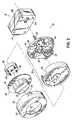
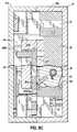
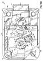
図1は、例えば構造体のドア12に結合された安全性の高いロック10の一実施形態を示しており、このロックは、ロック筐体14と、ユーザ入力デバイス15と、を有する。ロック10のこの実施形態におけるユーザ入力デバイス15は、ダイヤル筐体16内に配置された機械的ロックダイヤル24である。塵埃カバー18は、例えばスナップ嵌合コネクタ20を介して取り外し可能な態様でダイヤル筐体16に結合されてもよく、ロックダイヤル24が延出する開口部22を有する。ダイヤル24は、数字の組合せを入力するために回転されており、後述するように、組合せの数字は、ミラー28の反射を介してダイヤル筐体16にある窓部26を通して視認可能である。 FIG. 1 shows one embodiment of a highly
図2は、ユーザ入力デバイス15及びその内容物を示す分解図である。ダイヤル24は、ユーザによって手で把持される突出部分30と、その背面に数字の組合せの数字34(図3参照)を有する平面部分32と、を有する。真鍮のインサート36は、ネジ固定具38を用いてダイヤル24に強固に固定されている。真鍮のインサート36は、ダイヤル24に重量を付与し、ダイヤル筐体16の部分40に対して回転するための支持部材を提供する。ダイヤル筐体16は、ダイヤル平面部分40の背面にある数字をミラー28の反射を介して視認することを可能とするための窓部42、44を有する。LED表示発光部46は、組合せの入力の表示をもたらすためにさまざまな方法で設けられ、使用されてもよい。標準的な9ボルトのバッテリのようなバッテリ48は、バッテリドア50を通してダイヤル筐体16内に取り外し可能に配置されており、後述する電気回路及びサーボモータに電力を供給する。回転軸シャフト52は、正確な組合せコードを入力すると、ダイヤル24の回転をボルト後退ハードウエアに伝達するために設けられている。 FIG. 2 is an exploded view showing the
図3は、ロック10を示す背面斜視図であり、ロック筐体14から延出するロックボルト54を示している。シャフト52は、ロック筐体14の背面56を通って延出し、ダイヤル24を回転するとシャフト52の回転を可能とする態様でナット58によって固定されている。図3にさらに示されるように、ダイヤル平面部分32の背面は、組合せ数字を有しており、これは、ミラー28(図2)で反射されると、ユーザが視認可能となる。 FIG. 3 is a rear perspective view showing the
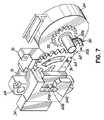
図4は、ロック10長手方向断面斜視図を示しており、このロックは、上述したさまざまな構成部材を有している。特に、軸シャフト52は、ダイヤル筐体16及びロック筐体14を通って完全に延出して示されている。1以上の軸スリーブ60は、その長さに沿って軸シャフト52を収容する。このようなスリーブ60は、ロック筐体14内に不意な侵入と、シャフト52が取り外された場合にさまざまなボルト後退ハードウエアへのアクセスと、を防止する。 FIG. 4 shows a longitudinal sectional perspective view of the
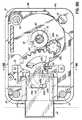
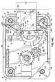
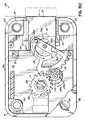
図5を参照すると、ロック筐体14は、分解形態で示されており、回路基板62及びさまざまなロックボルト後退ハードウエアを示し、これは、ボルト案内部材64と、ボルト54と、ボルト後退ギア68と、アクチュエータ70と、回動ブロック72と、回動ブロック72に固定されかつアクチュエータ70の回転出力素子76を覆うためのカバー74と、を有する。ロック筐体14は、前方筐体半体14aと、後方筐体半体14bと、を有する。回路基板62は、前方筐体半体14aの前方内面に配置されている。したがって、ドリルを使用してドア12の外側からロック筐体14内に穿孔する場合、ドリルのビットは、まず、回路基板62と接触し、ロック10をほぼ無能にし、このため、侵入をより困難とする。軸ギア78は、回転するために軸シャフト52及び接続されたダイヤル24(図4)に結合されている。軸ギア78は、駆動ギア素子80の第1ギア部分80aと噛合している。駆動ギア素子80の反対側のまたは第2ギア部分80bは、後方筐体半体14bにある開口部82を通って延出し、図6及び図7に示すように正確な組合せコードを入力すると、ボルト後退ギア68と噛合する。エンコーダ84は、シャフト52の回転を介して組合せコードの入力を検出するために使用され、電気回路62にある適切な制御回路と連動して使用される。 Referring to FIG. 5, the
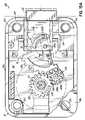
図8Aから図8C及び図9Aから図9Cと共に図6及び図7を参照して、ボルトの後退手順を説明する。エンコーダ及びコントローラによって認識されるように正確な組合せコードを入力すると、アクチュエータ70は、作動され、その出力素子76は、回転する。出力素子76は、ピン76aを有し、このピンは、回動ブロック72(図5)にあるスロット86を通って回転しかつボルト後退ギア68にあるスロット68cを通って移動する。通常、このピン76aは、例えば図8Aに示すように、ボルト後退ギア68の回転を防止する。しかしながら、図8Aから図8Cに示すように、アクチュエータ70の出力素子76が回転してピン76aを下方に移動させると、これは、ボルト後退ギア68が図8Aから図8Cに示すように時計回りに移動または回転することを可能とし、それは、駆動ギア素子80の第2部分80bと係合する。図示されていないが、ボルト後退ギア68は、例えばバネ力が小さいトーションバネによって若干バネ付勢されており、ボルト後退ギア68は、アクチュエータ70が作動するまで図8Bに示す位置まで時計回り方向に付勢する。いったんギア68、80bを図8Bに示すように係合すると、ダイヤル24は、手動で回転され、駆動ギア素子80は、軸ギア78との第1駆動ギア部分80aの係合を介して回転される。図8Aから図8Cに示すように、軸ギア78は、キー88によってシャフト52に結合されている。図8Bに示すように、ボルト後退ギア68を駆動ギア部分80bと係合すると、ボルト後退ギア68は、その回動軸68a回りで回転し、ボルト後退ギア68に固定されたピン68bは、ボルト案内部材64の凹所64aとボルト案内部材64の湾曲スロットまたはピンガイド90の端部90a(図5)とに載置される位置から出て上昇する。また、ピン68bは、ボルト54にあるスロット54aを通って延出し、ボルト後退ギア68が回転するにしたがって、ピン68bは、図8B及び図8Cに示すように、スロット54a内を上方向けて上昇し、同時に、ボルト54をロック筐体14内へボルト案内部材64を通って移動させる。ダイヤル24、シャフト52及びギア78、80、68を逆方向に回転させることにより、ボルト54をその完全に延出した位置まで延在させ、ボルト後退ギア68は、ピン76aによって図8Aに示す初期位置まで復帰される。その際、出力素子76は、バネ92を用いてバネ付勢されており、アクチュエータ70を作動停止すると、バネ92は、ピン76aを図9Aに示す初期位置まで復帰させ、出力素子76のバネ力は、ボルト後退ギア68を図8Aに示す初期位置まで復帰させるのに十分に強力である。 With reference to FIG. 6 and FIG. 7 together with FIG. 8A to FIG. 8C and FIG. 9A to FIG. Upon entering the correct combination code as recognized by the encoder and controller, the
ダイヤル平面部分32とミラー28とを用いることにより、空間が十分である態様でダイヤル筐体16内にバッテリ48を配置することが可能となる。ロック筐体部分14a、14bは、互いに機械的に固定されており、これらをこじ開けると、ロック筐体14を互いに固定している機械的素子(図示略)は、破損する。当然のことながら、ロック筐体14から延出するボルト94は、ロック筐体部分14a、14bを互いに固定しておらず、単にロック筐体14を例えばドア12に固定する機能を果たす。ロックへの別の不正な侵入方法は、外側からハンマーを用いて軸シャフト52をロック10に通させることを必要とする。しかしながら、このロックにおいて、これは、筐体14が動かず、したがって、他の安全性の高いロックで使用されているような「再ロック」機能を必要としない。アクチュエータ70は、図示の実施形態においてサーボモータ70である。マイクロサーボのようなサーボモータ70を用いることは、例えばステップモータとは対照的に、利点を有する。例えば、サーボモータ70は、比較的複雑なギアトレインを有しており、このギアトレインは、上述のように、単に部分的な回転を介して出力素子76を回転させるために複数回転を必要とする。このため、サーボモータ70は、いくつかの不正な方法で動作させること困難である.ボルト後退ギア68で使用されているピン68bは、図8Aに示すようにロックボルト54が延出した状態で、そのホーム位置において凹所内に載置される。したがって、ロックボルト54を不正な試みで内方に向けて押し込んでロック10を危険にさらす場合、力は、ギアトレインに対して掛からず、むしろボルト案内部材64に掛かり、このボルト案内部材は、大きな力に耐えるように設計されかつ構成されている。 By using the dial
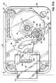
図10を参照すると、ロック10は、回路破損デバイス96をさらに有する。図示の実施形態における回路破損デバイス96は、第1端部96a及び第2端部96bを有する連続的な導電ワイヤからなり、各端部96a、96bは、回路基板62に電気的に接続されている。回路破損デバイス96は、ロック10のための初期制御回路内に一体的に接続されており、回路破損デバイス96が破損すると、ロック10は、動作不能になる。図10に示すように、回路破損デバイス96は、軸スリーブ60に近接して配置されており、このスリーブは、シャフト52がロック筐体14に入るように軸シャフト52を運ぶ。ロック10を破ろうとする権限のない人は、ユーザ入力デバイス15を取り外し、そしてロック筐体14の前方開口部において軸スリーブ60を穿孔しようとする。しかしながら、軸スリーブ60を介したロック筐体14に不正に侵入する試みは、回路破損デバイス96を破損させ、このため、ロック10へのこの攻撃方法を阻止する。回路破損デバイス96は、図10においてコイルとして示されており、このコイルは、軸スリーブ60に巻回されている。当業者が理解することは、回路破損デバイス96が複数のワイヤを備えてもよいことである。 With reference to FIG. 10, the
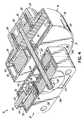
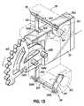
図11から図14Cを参照すると、ロック110の別の実施形態が示されている。図11におけるロック筐体14と内部ロックハードウエアとの分解図において最も明確に示されるように、ロック110は、回路基板62、ボルト後退ギア68及びアクチュエータ70のような第1実施形態のロック10と同様の素子を多数有している。この応用において、参照符号は、説明したさまざまな実施形態における同様の素子について同様のままとしている。この実施形態におけるロック110は、図6から図9Cに示されかつ上述したものと同じボルト後退手順に従い、ロック110は、別のロックボルト112及び後退ボルトシールド114を有する。ロックボルト112は、ボルト後退ギア68のピン68bを受けるように構成されたスロット112aを有する。ロックボルト112は、以下で詳述するように、後退ボルトシールド114で使用される向かい合う一対の凹所112bと、ボルト延出部112cと、をさらに有する。ボルト延出部112cは、ネジ固定具116によってロックボルト112に結合されており、このネジ固定具は、ボルト延出部112cをロックボルト112に配置するとボルト延出部112cの外面と同一平面に配置されている。図11の実施形態において、ボルト延出部112cは、約1/10(0.100)インチから3/16(0.1875)インチ(約2.54mmから4.7625mm)の厚さを有する。さまざまな政府受託業者は、米国政府のためにロックを製造しており、初期のロック製造者の1つは、後退するとロック筐体と同一平面になるロックボルトを設計し、一方、別の初期のロック製造者は、後退するとロック筐体を約3/16(0.1875)インチだけ越えて延出するロックボルトを設計した。ボルト延出部112cは、選択したドア12に必要な場合に、ロックボルト112に追加される。このため、ロックボルト112は、任意のタイプのドアに使用するように構成される。 Referring to FIGS. 11-14C, another embodiment of the
前の実施形態で示されるように、ロック筐体14の取付ボルト94は、ロック筐体14の背面56からアクセス可能となっている。この背面56にアクセスする権限のない人は、取付ネジ94を取り外し、ロック筐体14を異なる機構のロック本体に置換し、これにより、ロック110を危険にさらす。この問題に対処するため、現在の実施形態におけるロック110は、後退ボルトシールド114を有する。図11及び図12に示すように、ロック110は、改良型のボルト案内部材118を有する。ボルト案内部材118は、ボルト後退ギア68のピン68bを係合させるための凹所118a及び湾曲スロット120を有したままである。また、ボルト案内部材118は、ボルト案内部材118の両側に形成された長手方向を向く一対の開口部118bを有する。これら長手方向を向く開口部118bは、横方向を向くスロット118cと連通しており、スロット118cは、ボルト案内部材118の端部から取付ボルト94を保持する長手方向の受口部122まで延在する。後退ボルトシールド114は、非円形の開口部124aを有するブロック部材124と、非円形の開口部126aを有する第1部材126と、ブロック部材124を非円形の開口部124a、126aにおいて第1部材126に動作可能に結合する非円形の駆動ロッド128と、を有する。図13に最も明確に示すように、駆動ロッド128は、ボルト案内部材118の長手方向を向く一方の開口部118bの内に位置付けられ、ブロック部材124は、一方の横方向のスロット118c内に少なくとも部分的に配置されている。駆動ロッド128及び関連する開口部124a、126aは、図示の実施形態において六角形をなしているが、当業者が理解することは、任意の代替の非円形状をこれら素子に選択してもよいことである。第1部材126は、ロックボルト112、より具体的には、ロックボルトにある一方の凹所112bと係合するように構成されている。 As shown in the previous embodiment, the mounting
後退ボルトシールド114の動作は、図14Aから図14Cの手順で示されている。図14Aにおいて、ボルト後退ギア68は、単にギアトレイン78、80と係合しており、ロックボルト112の後退処理を開始する。ロックボルト112が延出位置にあると、ブロック部材124ロック110のボルト側にある取付ボルト94を完全に隠す。図14Bにおいて、ボルト後退ギア68は、移動してロックボルト112を部分的に後退させる。この動作状態において、ブロック部材124は、第1部材の第1端部126bがロックボルトの凹所112b内で移動しているが回転していないので、取付ボルト94を隠し続ける。ボルト後退ギア68がロックボルト112を後退し続けるにしたがって、凹所112bは、第1部材126を図14Cに示す位置まで回転させる。いったんロックボルト112をその位置まで完全に後退させると、駆動ロッド128は、第1部材126の運動をブロック部材124に伝達し、取付ロッド94を露出させる。軸ギア78がボルト後退ギア68及びロックボルト112を延出またはロック位置まで後退させるように駆動すると、第1部材126は、再度ロックボルトの凹所112bと係合し、図14Aにおける位置まで回転して戻る。このため、後退ボルトシールド114は、権限のない人が取付ボルト94を取り外すことによってロック110に手を加えようとすることを防止する。 The operation of the
同様の図示しない実施形態において、後退ボルトシールド114は、第2の一対のブロック部材を有し、このブロック部材が、単純な連結機構を介してボルト側のブロック部材124と共に回転するために結合されてもよい。この実施形態において、ボルト側のブロック部材124は、ロックボルト112が延出すると、ロック110の一方側にある取付ボルト94を隠し、第2の一対のブロック部材は、ロックボルトが後退すると、ロック110の反対側にある取付ボルト94を隠す。このため、権限のない人は、4つの取付ボルト94すべてにアクセスするために、組合せを用いてロック110を操作する必要がある。 In a similar non-illustrated embodiment, the receding
図15Aから図15Cを参照すると、さらなる実施形態におけるロック210が示されている。ロック210は、一部変更した状態で、図8Aから図9Cに示す上述したボルト後退手順とほぼ同様のボルト後退手順で動作する。ロック210は、軸ギア212と、軸ギア212に係合するように構成された第1駆動ギア部分214a及びと第2駆動ギア部分214bを有する駆動ギア214と、第2駆動ギア部分214bと係合するように構成されたボルト後退ギア216と、を有する。前の実施形態と同様に、ボルト後退ギア216は、回動軸216a及びピン216bを有しており、このピンは、ロックボルト54及びボルト案内部材64の対応するスロット54a、90内を動く。前の実施形態とは異なり、ボルト後退ギア216は、図15Aに示すようにロックボルト54が完全に延出すると、第2駆動ギア部分214bと係合したままである。2歯分の除去部220は、第1駆動ギア部分214aに形成されている。第1駆動ギア部分214aの除去部220は、図15Aに示すように、軸ギア212と駆動ギア214との係合を防止する一方で組合せの入力中に軸ギア212を回転させるように方向付けられている。このため、ダイヤル24を回転させている権限のない人には、ギアの衝突による可聴情報が提供されない。 Referring to FIGS. 15A-15C, a
いったん正確な組合せを入力すると、アクチュエータ70は、ボルト後退ギア216の経路から外に出力ピン76aをすぐには回転させない。その代わり、コントローラは、軸ギア212を図15Bに示す位置まで回転するまで待機し、軸ギア212にある除去部218は、駆動ギア214を向くように位置付けられる。この位置において、コントローラは、アクチュエータ70に信号を送信し、前に図9Aから図9Cで示したように、出力素子76及びピン76aをボルト後退ギア216の経路から外に回転させる。そして、ボルト後退ギア216は、図15Bに示すように、わずかに下方に回転し、このため、駆動ギア214を回転させ、第1駆動ギア部分214aの歯を軸ギア212と噛合させるための位置に移動させる。軸ギア212がダイヤル24と共に回転し続けるにしたがって、第1駆動ギア部分214aは、図15Cに示す位置まで駆動され、これは、第2駆動ギア部分214bを介してボルト後退ギア216の下方への回転に変換する。さらに、ピン216bは、ロックボルト54を押し込んで図15Cに示す位置に後退させ、このため、ロック210のボルト後退手順を完了する。 Once the correct combination is entered, the
さらなる実施形態におけるロック310を図16Aから図17Cに示す。ロック310は、前の実施形態におけるロック210と同様であり、軸ギア312と、軸ギア312と係合するように構成された第1駆動ギア部分314aと第2駆動ギア部分314bとを有する駆動ギア314と、第2駆動ギア部分314bと係合するように構成されたボルト後退ギア316と、を有する。軸ギア312及び第1駆動ギア部分314aには、ロック210において上述と同様の方法で、2歯分の除去部318、320が形成されている。この実施形態におけるロック310において、アクチュエータ70と関連する出力素子76とは、取り外されている。第2駆動ギア部分314bは、2歯分の除去部322を有しており、この除去部は、図16A及び図17Aに示すように、ロックボルト54が完全に延出するときに、ボルト後退ギア316と第2駆動ギア部分314aとが係合することを防止する。ボルト後退ギア316は、前の実施形態と同様の位置に初期的に位置付けられており、ギアの歯は、係合するために第2駆動ギア部分314bを向いている。 A
ロックボルト54を完全に延出させると、対向する駆動ギア部分314a、314bにある除去部320、322の方向付けは、軸ギア312及びボルト後退ギア316双方から駆動ギア314を係合解除するように設定されている。この実施形態における駆動ギア314は、入力シャフト324に取り付けられており、アクチュエータ326は、シャフト324の反対側の端部において駆動ギア314に動作可能に結合されている。アクチュエータ326は、回路基板62に近接して位置しており、シャフト324及び駆動ギア314を回転させるように構成されている。アクチュエータ326は、ギア式サーボモータ、非ギア式サーボモータまたは空気コア式回転ソレノイドのような低出力駆動デバイスである。正確な組合せをロック310に入力すると、回路基板62は、ダイヤル24が回転し、軸ギア312の除去部318が図16B及び図17Bに示すように第1駆動ギア部分314aを向くまで待機する。そして、回路基板62は、アクチュエータ326に信号を送信し、シャフト324及び駆動ギア314を回転させ、図16B及び図17Bに示すように、軸ギア312及びボルト後退ギア316双方と同時に係合させる。ユーザがダイヤル24を回転させるにしたがって、軸ギア312は、図16C及び図17Cに示す位置まで駆動ギア314及びボルト後退ギア316を駆動し、ロックボルト54は、完全に後退される。また、この実施形態におけるロック310は、組合せの入力中にギアの係合または衝突による可聴ノイズを除去し、アクチュエータ326は、前の実施形態におけるサーボモータ70の動作エネルギーのわずか10%だけを必要とする。したがって、この実施形態におけるロック310は、ドアへの権限のない侵入をさらに阻止する。 When the
図18を参照すると、代替の実施形態におけるロック410が示されている。ロック410は、ほぼ半透明な材料で形成されたロック筐体414を有し、ロック410の内部構成部材は、ロック筐体414の外部から視認可能となっている。ロック筐体414への権限のない侵入またはロック410を破壊する試みがある場合には、半透明なロック筐体414は、図18に示すように侵入の試みがあった証拠を明確に示す。筐体414を穿孔した穴部412は、ロックボルト54に近接して視認可能である。不透明なロック筐体と異なり、半透明なロック筐体414の穿孔した穴部412は、物質で継ぎ当てしてまたは充填して、ロック筐体414の背面56を検査する人によって検出されることなく試みた侵入を隠すことができない。さらに、半透明なロック筐体414を介したロック410の検査は、ロック410の構成部材における初期的な改竄または問題を明らかにする。当業者が理解することは、この実施形態における半透明な筐体414を説明した前の実施形態に使用し、権限なくロックを改竄することをさらにやめさせてもよいことである。 Referring to FIG. 18, an alternative embodiment lock 410 is shown. The lock 410 has a
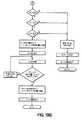
上述のように入力デバイス15としてロックダイヤル24を有するロック10、110、210、310、410の実施形態それぞれにおいて、回路基板62及びエンコーダ84は、図19Aから図20におけるダイアグラム化された特定の動作指示の組によってロック10を制御するようにプログラムされている。図19A及び図19Bの動作モードにおいて、ロックダイヤル24の反時計回りの回転をいったん検出すると、ロック給電部は、始動し、最後にロックをロック解除してから図られた不正確な組合せの入力数を示す値Pと共に認証情報または正確な組合値X、Y、Zを得る。LED46は、P回だけ赤色に点滅し、権限のあるロックのユーザが、いつ別人がドア12を破ろうと試みて失敗したかを知ることを可能とする。これらペナルティの点滅後、LED46は、1回のダイヤルの回転に対して赤色及び緑色に点滅し、途切れのない緑色になる。いったん反時計回りの回転を停止して時計回りの回転が開始したことをコントローラが検出すると、コントローラは、停止時に入力されたダイヤル値をX1として記憶し、Y1及びZ1値を得るための処理を繰り返す。そして、コントローラは、入力したダイヤル値Z1、Y1、Z1が正確な組合値X、Y、Zと一致するか検証する。値が一致しない場合、LED46は、10秒間赤色に点滅し、P値は、ロック10の電力を停止する前に1だけ増加される。値が一致した場合、サーボモータ70またはアクチュエータ326は、係合し、ボルト54を後退させ、P値は、ゼロに設定される。ロックボルト54が解放または後退位置にある限り、LED46は、10秒ごとに1回赤色に点滅し、ロック10が開放位置にあることを示す。いったんロックボルト54を延出位置まで戻すと、ロック電力は、停止される。 In each of the embodiments of the
図20を参照すると、変更キーをロック10に挿入すると設定モードが作動される。ロック電力は、始動し、メモリから正確な組合値X、Y、Zを得る。いったんダイヤルの反時計回りの回転を検出すると、ロックは、図19A及び図19Bにおいて上述した手順にしたがってユーザの入力値X1、Y1、Z1を得る。5秒の一時停止後、ユーザの入力を得る処理は、繰り返され、値X2、Y2、Z2を記憶する。そして、コントローラは、2つの組みのユーザの入力値の平均値に等しい正確な組合値X、Y、Zを設定する。したがって、設定モードは、所望の新たな組合せが正確に設定されたことを検証する。 Referring to FIG. 20, when the change key is inserted into the
当業者が理解することは、ロック10、110、210、310、410のさまざまな実施形態が機械的なロックダイヤル24に替えて別のユーザ入力デバイス15で動作されてもよいことである。例えば、組合値を電子的に入力するために、電子キーパッドをドア12の外側に位置してもよい。あるいは、ユーザ入力デバイス15は、指紋または網膜スキャン検証デバイスを有してもよい。ロック筐体14内に位置付けられているロック10の内部構成部材は、選択したユーザ入力デバイス15にかかわらず上述のように動作する。 Those skilled in the art will appreciate that the various embodiments of the
本発明がいくつかの実施形態の説明によって例示されており、このような実施形態を相当に詳細に説明したが、このような詳細にまで添付の特許請求の範囲を限定または制限することを意図していない。さらなる利点及び改良は、当業者にすでに明らかである。例えば、図20に詳述されている設定モードは、3つの組みのユーザの入力値を必要として新たな組合せを設定するために共に平均化されるように改良されてもよい。したがって、その最も広範な態様における本発明は、図示されかつ説明された具体的な詳細にまで制限されない。本明細書で開示されたさまざまな機能は、特定の用途に必要なまたは望ましい組合せで使用されてもよい。したがって、以下の特許請求の範囲の精神及び範囲から逸脱することなく本明細書で説明された詳細から逸脱してなされてもよい。 While the invention has been illustrated by the description of several embodiments, and such embodiments have been described in considerable detail, it is intended that the scope of the appended claims be limited or limited to such details. Not done. Further advantages and improvements are already apparent to those skilled in the art. For example, the setting mode detailed in FIG. 20 may be modified to require three sets of user input values and be averaged together to set a new combination. Accordingly, the invention in its broadest aspects is not limited to the specific details shown and described. The various functions disclosed herein may be used in any combination necessary or desirable for a particular application. Accordingly, departures may be made from the details described herein without departing from the spirit and scope of the following claims.
10,110,210,310,410 ロック(ロック機構)、14,414 ロック筐体,筐体、15 ユーザ入力デバイス,入力デバイス、24 機械的ロックダイヤル,ロックダイヤル,ダイヤル、46 LED表示発光部,LED、52 回転軸シャフト,軸シャフト,シャフト、54,112 ロックボルト,ボルト、54a,112a スロット(ロックボルトのスロット)、60 軸スリーブ,スリーブ、62 電気回路,回路基板、68,216,316 ボルト後退ギア、68a,216a 回動軸、68b,216b ピン(後退ピン)、70 アクチュエータ,サーボモータ、72 回動ブロック(ブロック部材)、76 回転出力素子,出力素子、76a 出力ピン,ピン(ブロックピン)、78,212,312 軸ギア(ギアトレイン)、80,214,314 駆動ギア素子,駆動ギア(ギアトレイン)、80a,214a,314a 第1駆動ギア部分,第1ギア部分,部分、80b,214b,314b 第2駆動ギア部分,第2ギア部分,部分、86 スロット(駆動ギアのスロット)、90 ピンガイド,スロット、94 取付ネジ,取付ボルト,取付ロッド,ボルト、96 回路破損デバイス、112b 凹所、112c ボルト延出部、114 後退ボルトシールド、122 受口部(ボルト受口部,取付ボルト受口部)、124 ブロック部材、126 第1部材、128 駆動ロッド、218,220,318,320,322 除去部(除去部分)10, 110, 210, 310, 410 lock (lock mechanism), 14,414 lock housing, housing, 15 user input device, input device, 24 mechanical lock dial, lock dial, dial, 46 LED display light emitting unit, LED, 52 Rotating shaft, Shaft, Shaft, 54, 112 Rock bolt, Bolt, 54a, 112a Slot (lock bolt slot), 60 Shaft, sleeve, 62 Electrical circuit, Circuit board, 68, 216, 316 Bolt Reverse gear, 68a, 216a Rotating shaft, 68b, 216b Pin (reverse pin), 70 Actuator, Servo motor, 72 Rotating block (block member), 76 Rotation output element, output element, 76a Output pin, pin (block pin) ), 78, 212, 312 shaft gear ( Atrain), 80, 214, 314 driving gear element, driving gear (gear train), 80a, 214a, 314a first driving gear portion, first gear portion, portion, 80b, 214b, 314b second driving gear portion, second Gear part, part, 86 slot (drive gear slot), 90 pin guide, slot, 94 mounting screw, mounting bolt, mounting rod, bolt, 96 circuit breakage device, 112b recess, 112c bolt extension, 114 reverse bolt Shield, 122 receiving portion (bolt receiving portion, mounting bolt receiving portion), 124 block member, 126 first member, 128 driving rod, 218, 220, 318, 320, 322 removing portion (removing portion)
Claims (73)
Translated fromJapanese前記ロックボルトに動作可能に結合され、係合及び係合解除位置間で移動可能なボルト後退ギアであって、前記係合位置に向けてバネ付勢されている、ボルト後退ギアと、
手動で駆動されるギアトレインであって、前記係合位置にある前記ボルト後退ギアと係合しかつ続いて前記ロックボルトを前記延出及び後退位置間で駆動する、ギアトレインと、
ユーザの入力情報を受けるユーザ入力デバイスと、
認証情報を記憶し、ユーザの入力情報を検証するように構成された、電気回路を備えるコントローラと、
回転可能な出力素子を有するアクチュエータであって、回転可能な前記出力素子が、ユーザの入力情報が記憶された認証情報と一致することを前記コントローラが検証するまで、前記ギアトレインと係合するための前記ボルト後退ギアの前記係合位置への移動を妨害する、アクチュエータと、
を備えることを特徴とするロック機構。A lock bolt movable between extended and retracted positions;
A bolt retraction gear operably coupled to the lock bolt and movable between an engagement and disengagement position, wherein the bolt retraction gear is spring biased toward the engagement position;
A gear train driven manually,it drives thefront Symbol lock bolt between the extended and out and retracted positionsFollowing the bolt reverse gear engagesvital in the engagedposition, and a gear train,
A user input device that receives user input information; and
A controller comprising an electrical circuit configured to store authentication information and verify user input information;
An actuator having a rotatable output element, wherein the rotatable output elementengages the gear train untilthe controller verifies that user input information matches stored authentication information. interfere with the movement to the engagement positionbefore Symbol bolt retractiongear, an actuator,
A locking mechanism comprising:
前記認証情報は、数字の組合せであることを特徴とする請求項1に記載のロック機構。The user input device is a rotatable lock dial;
The lock mechanism according to claim 1, wherein the authentication information is a combination of numbers.
前記ロックダイヤルは、回転されてユーザの入力情報を入力し、かつ、ユーザの入力情報が検証されると、前記ロックボルトを前記延出位置から前記後退位置まで移動させることを特徴とする請求項2に記載のロック機構。Further comprising an axial shaft coupling the rotatable lock dial to the manually driven gear train;
The lock dial is rotated to input user input information, and when the user input information is verified, the lock bolt is moved from the extended position to the retracted position. 2. The locking mechanism according to 2.
回転可能な前記出力素子は、ブロックピンをさらに備え、
前記ブロックピンは、前記係合解除位置において前記ボルト後退ギアの前記スロット内に配置され、前記ボルト後退ギアの移動を妨害することを特徴とする請求項1に記載のロック機構。The bolt reverse gear further comprises a slot,
The rotatable output element further comprises a block pin,
The lock mechanism according to claim 1, wherein the block pin is disposed in the slot of the bolt reverse gear at the disengagement position and obstructs the movement of the bolt reverse gear.
前記ボルト後退ギアは、回動軸及び後退ピンをさらに備え、
前記後退ピンは、前記ボルト後退ギアが前記回動軸回りで回転して前記ロックボルトを後退及び延出させるにしたがって、前記ロックボルトの前記スロットに沿ってスライドすることを特徴とする請求項1に記載のロック機構。The lock bolt further includes a slot,
The bolt reverse gear further includes a rotation shaft and a reverse pin,
2. The retraction pin is slid along the slot of the lock bolt as the bolt retraction gear rotates around the rotation shaft to retract and extend the lock bolt. The locking mechanism described in 1.
前記ロックボルトは、前記後退位置において前記ロック筐体と同一平面にあることを特徴とする請求項1に記載のロック機構。A lock housing surrounding the actuator, the controller, the manually driven gear train and the bolt reverse gear;
The lock mechanism according to claim 1, wherein the lock bolt is flush with the lock housing in the retracted position.
前記ロックボルトと前記ロックボルト延出部との組合せは、前記後退位置において前記ロック筐体を越えて突出することを特徴とする請求項10に記載のロック機構。A lock bolt extending portion coupled to the lock bolt;
The lock mechanism according to claim 10, wherein the combination of the lock bolt and the lock bolt extending portion protrudes beyond the lock housing in the retracted position.
前記ロック筐体は、前記回路基板に隣接する軸スリーブをさらに備え、
手動で駆動される前記ギアトレインは、前記ロック筐体の外側から前記軸スリーブを通って延在する軸シャフトをさらに備え、
当該ロック機構は、
前記軸スリーブに隣接しかつ前記コントローラに配線接続された回路破損デバイスであって、前記軸スリーブを介した穿孔が当該回路破損デバイスを破損して前記コントローラを動作不能にさせる、回路破損デバイスをさらに備えることを特徴とする請求項12に記載のロック機構。The controller includes a circuit board,
The lock housing further includes a shaft sleeve adjacent to the circuit board;
The manually driven gear train further comprises a shaft shaft extending through the shaft sleeve from the outside of the lock housing;
The locking mechanism is
A circuit breakage device adjacent to the shaft sleeve and wired to the controller, wherein a perforation through the shaft sleeve breaks the circuit break device and renders the controller inoperable. The locking mechanism according to claim 12, comprising: a locking mechanism.
前記ロックボルトは、凹所を有し、
当該ロック機構は、
ブロック部材に結合される第1部材を有する後退ボルトシールドをさらに備え、
前記ブロック部材は、前記取付ボルト受口部内の取付ボルトを覆う妨害位置と前記取付ボルト受口部の外側の非妨害位置との間で移動可能であり、
前記第1部材は、前記ロックボルトの前記凹所内に配置され、前記ロックボルトが前記延出位置から前記後退位置まで移動するにしたがって、前記ブロック部材を前記妨害位置から前記非妨害位置まで駆動するように構成されていることを特徴とする請求項13に記載のロック機構。The lock housing further includes a mounting bolt receiving portion,
The lock bolt has a recess;
The locking mechanism is
Further comprising a receding bolt shield having a first member coupled to the block member;
The block member is movable between an obstructing position that covers the mounting bolt in the mounting bolt receiving part and a non-obstructing position outside the mounting bolt receiving part,
The first member is disposed in the recess of the lock bolt, and drives the block member from the blocking position to the non-blocking position as the lock bolt moves from the extended position to the retracted position. The lock mechanism according to claim 13, which is configured as described above.
前記ロック筐体は、前記回路基板に隣接する軸スリーブをさらに備え、
手動で駆動される前記ギアトレインは、前記ロック筐体の外側から前記軸スリーブを通って延在する軸シャフトをさらに備え、
当該ロック機構は、
前記軸スリーブに隣接しかつ前記コントローラに配線接続された回路破損デバイスであって、前記軸スリーブを介した穿孔が当該回路破損デバイスを破損して前記コントローラを動作不能にさせる、回路破損デバイスをさらに備えることを特徴とする請求項10に記載のロック機構。The controller includes a circuit board,
The lock housing further includes a shaft sleeve adjacent to the circuit board;
The manually driven gear train further comprises a shaft shaft extending through the shaft sleeve from the outside of the lock housing;
The locking mechanism is
A circuit breakage device adjacent to the shaft sleeve and wired to the controller, wherein a perforation through the shaft sleeve breaks the circuit break device and renders the controller inoperable. The lock mechanism according to claim 10, further comprising:
前記ロックボルトは、凹所を有し、
当該ロック機構は、
ブロック部材に結合される第1部材を有する後退ボルトシールドをさらに備え、
前記ブロック部材は、前記取付ボルト受口部内の取付ボルトを覆う妨害位置と前記取付ボルト受口部の外側の非妨害位置との間で移動可能であり、
前記第1部材は、前記ロックボルトの前記凹所内に配置され、前記ロックボルトが前記延出位置から前記後退位置まで移動するにしたがって、前記ブロック部材を前記妨害位置から前記非妨害位置まで駆動するように構成されていることを特徴とする請求項15に記載のロック機構。The lock housing further includes a mounting bolt receiving portion,
The lock bolt has a recess;
The locking mechanism is
Further comprising a receding bolt shield having a first member coupled to the block member;
The block member is movable between an obstructing position that covers the mounting bolt in the mounting bolt receiving part and a non-obstructing position outside the mounting bolt receiving part,
The first member is disposed in the recess of the lock bolt, and drives the block member from the blocking position to the non-blocking position as the lock bolt moves from the extended position to the retracted position. The lock mechanism according to claim 15, configured as described above.
前記ロックボルトは、凹所を有し、
当該ロック機構は、
ブロック部材に結合される第1部材を有する後退ボルトシールドをさらに備え、
前記ブロック部材は、前記取付ボルト受口部内の取付ボルトを覆う妨害位置と前記取付ボルト受口部の外側の非妨害位置との間で移動可能であり、
前記第1部材は、前記ロックボルトの前記凹所内に配置され、前記ロックボルトが前記延出位置から前記後退位置まで移動するにしたがって、前記ブロック部材を前記妨害位置から前記非妨害位置まで駆動するように構成されていることを特徴とする請求項10に記載のロック機構。The lock housing further includes a mounting bolt receiving portion,
The lock bolt has a recess;
The locking mechanism is
Further comprising a receding bolt shield having a first member coupled to the block member;
The block member is movable between an obstructing position that covers the mounting bolt in the mounting bolt receiving part and a non-obstructing position outside the mounting bolt receiving part,
The first member is disposed in the recess of the lock bolt, and drives the block member from the blocking position to the non-blocking position as the lock bolt moves from the extended position to the retracted position. The lock mechanism according to claim 10, wherein the lock mechanism is configured as described above.
前記ロックボルトに動作可能に結合されたボルト後退ギアと、
手動で駆動されるギアトレインであって、前記ボルト後退ギアに係合される軸ギア及び駆動ギアを有し、前記駆動ギアが、除去部分を有し、前記軸ギアとの係合位置と前記除去部分が前記軸ギアと向かい合う係合解除位置との間で移動可能であり、前記駆動ギアが前記ボルト後退ギアによって前記係合位置に向けて付勢されている、ギアトレインと、
ユーザの入力情報を受けるユーザ入力デバイスと、
認証情報を記憶し、ユーザの入力情報を検証するように構成された、電気回路を備えるコントローラと、
回転可能な出力素子を有するアクチュエータであって、回転可能な前記出力素子が、前記ボルト後退ギアの移動を妨害し、これにより、ユーザの入力情報が記憶された認証情報を一致することを前記コントローラが検証するまで、前記駆動ギアの前記係合解除位置から前記係合位置への回転を防止する、アクチュエータと、
を備えることを特徴とするロック機構。A lock bolt movable between extended and retracted positions;
A bolt retraction gear operably coupled to the lock bolt;
A manually driven gear train having a shaft gear and a drive gear engaged with the bolt reverse gear, the drive gear having a removal portion, and an engagement position with the shaft gear and the A gear train, wherein a removal portion is movable between a disengagement position facing the shaft gear, and the drive gear is biased toward the engagement position by the bolt reverse gear;
A user input device that receives user input information; and
A controller comprising an electrical circuit configured to store authentication information and verify user input information;
An actuator having a rotatable output element, wherein the rotatable output element interferes with the movement of the bolt reverse gear so that the user input information matches the stored authentication information. An actuator for preventing rotation of the drive gear from the disengaged position to the engaged position until
A locking mechanism comprising:
前記認証情報は、数字の組合せであることを特徴とする請求項18に記載のロック機構。The user input device is a rotatable lock dial;
The lock mechanism according to claim 18, wherein the authentication information is a combination of numbers.
前記ロックダイヤルは、回転されてユーザの入力情報を入力し、かつ、ユーザの入力情報が検証されると、前記ロックボルトを前記延出位置から前記後退位置まで移動させることを特徴とする請求項19に記載のロック機構。Further comprising an axial shaft coupling the rotatable lock dial to the manually driven gear train;
The lock dial is rotated to input user input information, and when the user input information is verified, the lock bolt is moved from the extended position to the retracted position. The locking mechanism according to 19.
前記アクチュエータは、前記軸ギアの前記除去部分が前記駆動ギアと向かい合うときだけ、前記ボルト後退ギアを移動させて前記駆動ギアを前記係合解除位置から前記係合位置まで回転させるように構成されることを特徴とする請求項18に記載のロック機構。The shaft gear has a removal portion;
The actuator is configured to move the bolt reverse gear and rotate the drive gear from the disengaged position to the engaged position only when the removed portion of the shaft gear faces the drive gear. The locking mechanism according to claim 18.
回転可能な前記出力素子は、ブロックピンをさらに備え、
前記ブロックピンは、前記係合解除位置において前記ボルト後退ギアの前記スロット内に配置され、前記ボルト後退ギアの移動を妨害することを特徴とする請求項18に記載のロック機構。The bolt reverse gear further comprises a slot,
The rotatable output element further comprises a block pin,
19. The lock mechanism according to claim 18, wherein the block pin is disposed in the slot of the bolt reverse gear at the disengagement position and obstructs the movement of the bolt reverse gear.
前記ボルト後退ギアは、回動軸及び後退ピンをさらに備え、
前記後退ピンは、前記ボルト後退ギアが前記回動軸回りで回転して前記ロックボルトを後退及び延出させるにしたがって、前記ロックボルトの前記スロットに沿ってスライドすることを特徴とする請求項18に記載のロック機構。The lock bolt further includes a slot,
The bolt reverse gear further includes a rotation shaft and a reverse pin,
19. The retraction pin slides along the slot of the lock bolt as the bolt retraction gear rotates about the pivot shaft to retract and extend the lock bolt. The locking mechanism described in 1.
前記ロックボルトは、前記後退位置において前記ロック筐体と同一平面にあることを特徴とする請求項18に記載のロック機構。A lock housing surrounding the actuator, the controller, the manually driven gear train and the bolt reverse gear;
The lock mechanism according to claim 18, wherein the lock bolt is flush with the lock housing in the retracted position.
前記ロックボルトと前記ロックボルト延出部との組合せは、前記後退位置において前記ロック筐体を越えて突出することを特徴とする請求項27に記載のロック機構。A lock bolt extending portion coupled to the lock bolt;
28. The lock mechanism according to claim 27, wherein the combination of the lock bolt and the lock bolt extending portion protrudes beyond the lock housing in the retracted position.
前記ロック筐体は、前記回路基板に隣接する軸スリーブをさらに備え、
手動で駆動される前記ギアトレインは、前記ロック筐体の外側から前記軸スリーブを通って延在する軸シャフトをさらに備え、
当該ロック機構は、
前記軸スリーブに隣接しかつ前記コントローラに配線接続された回路破損デバイスであって、前記軸スリーブを介した穿孔が当該回路破損デバイスを破損して前記コントローラを動作不能にさせる、回路破損デバイスをさらに備えることを特徴とする請求項29に記載のロック機構。The controller includes a circuit board,
The lock housing further includes a shaft sleeve adjacent to the circuit board;
The manually driven gear train further comprises a shaft shaft extending through the shaft sleeve from the outside of the lock housing;
The locking mechanism is
A circuit breakage device adjacent to the shaft sleeve and wired to the controller, wherein a perforation through the shaft sleeve breaks the circuit break device and renders the controller inoperable. 30. The locking mechanism according to claim 29, comprising: a locking mechanism.
前記ロックボルトは、凹所を有し、
当該ロック機構は、
ブロック部材に結合される第1部材を有する後退ボルトシールドをさらに備え、
前記ブロック部材は、前記取付ボルト受口部内の取付ボルトを覆う妨害位置と前記取付ボルト受口部の外側の非妨害位置との間で移動可能であり、
前記第1部材は、前記ロックボルトの前記凹所内に配置され、前記ロックボルトが前記延出位置から前記後退位置まで移動するにしたがって、前記ブロック部材を前記妨害位置から前記非妨害位置まで駆動するように構成されていることを特徴とする請求項30に記載のロック機構。The lock housing further includes a mounting bolt receiving portion,
The lock bolt has a recess;
The locking mechanism is
Further comprising a receding bolt shield having a first member coupled to the block member;
The block member is movable between an obstructing position that covers the mounting bolt in the mounting bolt receiving part and a non-obstructing position outside the mounting bolt receiving part,
The first member is disposed in the recess of the lock bolt, and drives the block member from the blocking position to the non-blocking position as the lock bolt moves from the extended position to the retracted position. 31. The locking mechanism according to claim 30, wherein the locking mechanism is configured as described above.
前記ロック筐体は、前記回路基板に隣接する軸スリーブをさらに備え、
手動で駆動される前記ギアトレインは、前記ロック筐体の外側から前記軸スリーブを通って延在する軸シャフトをさらに備え、
当該ロック機構は、
前記軸スリーブに隣接しかつ前記コントローラに配線接続された回路破損デバイスであって、前記軸スリーブを介した穿孔が当該回路破損デバイスを破損して前記コントローラを動作不能にさせる、回路破損デバイスをさらに備えることを特徴とする請求項27に記載のロック機構。The controller includes a circuit board,
The lock housing further includes a shaft sleeve adjacent to the circuit board;
The manually driven gear train further comprises a shaft shaft extending through the shaft sleeve from the outside of the lock housing;
The locking mechanism is
A circuit breakage device adjacent to the shaft sleeve and wired to the controller, wherein a perforation through the shaft sleeve breaks the circuit break device and renders the controller inoperable. The locking mechanism according to claim 27, comprising: a locking mechanism.
前記ロックボルトは、凹所を有し、
当該ロック機構は、
ブロック部材に結合される第1部材を有する後退ボルトシールドをさらに備え、
前記ブロック部材は、前記取付ボルト受口部内の取付ボルトを覆う妨害位置と前記取付ボルト受口部の外側の非妨害位置との間で移動可能であり、
前記第1部材は、前記ロックボルトの前記凹所内に配置され、前記ロックボルトが前記延出位置から前記後退位置まで移動するにしたがって、前記ブロック部材を前記妨害位置から前記非妨害位置まで駆動するように構成されていることを特徴とする請求項32に記載のロック機構。The lock housing further includes a mounting bolt receiving portion,
The lock bolt has a recess;
The locking mechanism is
Further comprising a receding bolt shield having a first member coupled to the block member;
The block member is movable between an obstructing position that covers the mounting bolt in the mounting bolt receiving part and a non-obstructing position outside the mounting bolt receiving part,
The first member is disposed in the recess of the lock bolt, and drives the block member from the blocking position to the non-blocking position as the lock bolt moves from the extended position to the retracted position. The locking mechanism according to claim 32, wherein the locking mechanism is configured as described above.
前記ロックボルトは、凹所を有し、
当該ロック機構は、
ブロック部材に結合される第1部材を有する後退ボルトシールドをさらに備え、
前記ブロック部材は、前記取付ボルト受口部内の取付ボルトを覆う妨害位置と前記取付ボルト受口部の外側の非妨害位置との間で移動可能であり、
延出位置から前記後退位置まで移動するにしたがって、前記ブロック部材を前記妨害位置から前記非妨害位置まで駆動するように構成されていることを特徴とする請求項27に記載のロック機構。The lock housing further includes a mounting bolt receiving portion,
The lock bolt has a recess;
The locking mechanism is
Further comprising a receding bolt shield having a first member coupled to the block member;
The block member is movable between an obstructing position that covers the mounting bolt in the mounting bolt receiving part and a non-obstructing position outside the mounting bolt receiving part,
28. The locking mechanism according to claim 27, wherein the block member is configured to be driven from the blocking position to the non-blocking position as it moves from the extended position to the retracted position.
前記ロックボルトに動作可能に結合されたボルト後退ギアと、
手動で駆動される軸ギアと、
駆動シャフトに取り付けられた駆動ギアであって、第1及び第2除去部分を有し、当該駆動ギアが、当該駆動ギアが前記軸ギア及び前記ボルト後退ギア双方と係合する係合位置と前記第1除去部分が前記軸ギアと向かい合いかつ前記第2除去部分が前記ボルト後退ギアと向かい合う係合解除位置との間で移動可能である、駆動ギアと、
ユーザの入力情報を受けるユーザ入力デバイスと、
認証情報を記憶し、ユーザの入力情報を検証するように構成された、電気回路を備えるコントローラと、
前記駆動シャフトに結合されたアクチュエータであって、前記駆動ギアを前記係合解除位置から前記係合位置まで移動させるように構成され、前記軸ギアが、前記コントローラがユーザの入力情報が記憶された認証情報と一致することを検証すると、前記延出及び前記後退位置間で前記ロックボルトを駆動する、アクチュエータと、
前記アクチュエータ、前記コントローラ、前記軸ギア、前記駆動ギア及び前記ボルト後退ギアを囲むロック筐体であって、当該ロック筐体が前記後退位置にある状態で、前記ロックボルトが当該ロック筐体と同一平面にある、ロック筐体と、
前記ロックボルトに結合されたロックボルト延出部であって、前記ロックボルトと前記ロックボルト延出部との組合せは、前記後退位置において前記ロック筐体を越えて突出する、ロックボルト延出部と、
を備えることを特徴とするロック機構。A lock bolt movable between extended and retracted positions;
A bolt retraction gear operably coupled to the lock bolt;
A manually driven shaft gear;
A drive gear attached to the drive shaft, having first and second removal portions, wherein the drive gear engages with both the shaft gear and the bolt reverse gear; and A drive gear movable between a disengagement position wherein a first removal portion faces the shaft gear and the second removal portion faces the bolt reverse gear;
A user input device that receives user input information; and
A controller comprising an electrical circuit configured to store authentication information and verify user input information;
An actuator coupled to the drive shaft configured to move the drive gear from the disengagement position to the engagement position, the shaft gear storing information input by the controller by the controller Verifying that it matches the authentication information, an actuator that drives the lock bolt between the extended and retracted positions;
A lock casing surrounding the actuator, the controller, the shaft gear, the drive gear, and the bolt retraction gear, wherein the lock bolt is the same as the lock casing when the lock casing is in the retracted position. A lock housing in a plane;
A lock bolt extension portion coupled to the lock bolt, wherein the combination of the lock bolt and the lock bolt extension portion projects beyond the lock housing in the retracted position. When,
A locking mechanism comprising:
前記認証情報は、数字の組合せであることを特徴とする請求項35に記載のロック機構。The user input device is a rotatable lock dial;
36. The locking mechanism according to claim 35, wherein the authentication information is a combination of numbers.
前記ロックダイヤルは、回転されてユーザの入力情報を入力し、かつ、ユーザの入力情報が検証されると、前記ロックボルトを前記延出位置から前記後退位置まで移動させることを特徴とする請求項36に記載のロック機構。Further comprising an axial shaft coupling the rotatable lock dial to the manually driven gear train;
The lock dial is rotated to input user input information, and when the user input information is verified, the lock bolt is moved from the extended position to the retracted position. 36. The locking mechanism according to 36.
前記アクチュエータは、前記軸ギアの前記除去部分が前記駆動ギアと向かい合うときだけ、前記駆動ギアを前記係合解除位置から前記係合位置まで移動させるように構成されることを特徴とする請求項35に記載のロック機構。The shaft gear has a removal portion;
36. The actuator is configured to move the drive gear from the disengaged position to the engaged position only when the removed portion of the shaft gear faces the drive gear. The locking mechanism described in 1.
前記ボルト後退ギアは、回動軸及び後退ピンをさらに備え、
前記後退ピンは、前記ボルト後退ギアが前記回動軸回りに回転して前記ロックボルトを後退及び延出させるにしたがって、前記スロットに沿ってスライドすることを特徴とする請求項35に記載のロック機構。The lock bolt further includes a slot,
The bolt reverse gear further includes a rotation shaft and a reverse pin,
36. The lock of claim 35, wherein the retraction pin slides along the slot as the bolt retraction gear rotates about the pivot axis to retract and extend the lock bolt. mechanism.
前記ロック筐体は、前記回路基板に隣接する軸スリーブをさらに備え、
手動で駆動される前記ギアトレインは、前記ロック筐体の外側から前記軸スリーブを通って延在する軸シャフトをさらに備え、
当該ロック機構は、
前記軸スリーブに隣接しかつ前記コントローラに配線接続された回路破損デバイスであって、前記軸スリーブを介した穿孔を試みることが当該回路破損デバイスを破損して前記コントローラを動作不能にさせる、回路破損デバイスをさらに備えることを特徴とする請求項41に記載のロック機構。The controller includes a circuit board,
The lock housing further includes a shaft sleeve adjacent to the circuit board;
The manually driven gear train further comprises a shaft shaft extending through the shaft sleeve from the outside of the lock housing;
The locking mechanism is
A circuit breakage device adjacent to the shaft sleeve and wired to the controller, wherein attempting to drill through the shaft sleeve breaks the circuit break device and renders the controller inoperable 42. The locking mechanism according to claim 41, further comprising a device.
前記ロックボルトは、凹所を有し、
当該ロック機構は、
ブロック部材に結合される第1部材を有する後退ボルトシールドをさらに備え、
前記ブロック部材は、前記取付ボルト受口部内の取付ボルトを覆う妨害位置と前記取付ボルト受口部の外側の非妨害位置との間で移動可能であり、
前記第1部材は、前記ロックボルトの前記凹所内に配置され、前記ロックボルトが前記延出位置から前記後退位置まで移動するにしたがって、前記ブロック部材を前記妨害位置から前記非妨害位置まで駆動するように構成されていることを特徴とする請求項42に記載のロック機構。The lock housing further includes a mounting bolt receiving portion,
The lock bolt has a recess;
The locking mechanism is
Further comprising a receding bolt shield having a first member coupled to the block member;
The block member is movable between an obstructing position that covers the mounting bolt in the mounting bolt receiving part and a non-obstructing position outside the mounting bolt receiving part,
The first member is disposed in the recess of the lock bolt, and drives the block member from the blocking position to the non-blocking position as the lock bolt moves from the extended position to the retracted position. 43. The locking mechanism according to claim 42, configured as described above.
前記ロック筐体は、前記回路基板に隣接する軸スリーブをさらに備え、
手動で駆動される前記ギアトレインは、前記ロック筐体の外側から前記軸スリーブを通って延在する軸シャフトをさらに備え、
当該ロック機構は、
前記軸スリーブに隣接しかつ前記コントローラに配線接続された回路破損デバイスであって、前記軸スリーブを介した穿孔が当該回路破損デバイスを破損して前記コントローラを動作不能にさせる、回路破損デバイスをさらに備えることを特徴とする請求項35に記載のロック機構。The controller includes a circuit board,
The lock housing further includes a shaft sleeve adjacent to the circuit board;
The manually driven gear train further comprises a shaft shaft extending through the shaft sleeve from the outside of the lock housing;
The locking mechanism is
A circuit breakage device adjacent to the shaft sleeve and wired to the controller, wherein a perforation through the shaft sleeve breaks the circuit break device and renders the controller inoperable. 36. The locking mechanism according to claim 35, comprising: a locking mechanism.
前記ロックボルトは、凹所を有し、
当該ロック機構は、
ブロック部材に結合される第1部材を有する後退ボルトシールドをさらに備え、
前記ブロック部材は、前記取付ボルト受口部内の取付ボルトを覆う妨害位置と前記取付ボルト受口部の外側の非妨害位置との間で移動可能であり、
前記第1部材は、前記ロックボルトの前記凹所内に配置され、前記ロックボルトが前記延出位置から前記後退位置まで移動するにしたがって、前記ブロック部材を前記妨害位置から前記非妨害位置まで駆動するように構成されていることを特徴とする請求項44に記載のロック機構。The lock housing further includes a mounting bolt receiving portion,
The lock bolt has a recess;
The locking mechanism is
Further comprising a receding bolt shield having a first member coupled to the block member;
The block member is movable between an obstructing position that covers the mounting bolt in the mounting bolt receiving part and a non-obstructing position outside the mounting bolt receiving part,
The first member is disposed in the recess of the lock bolt, and drives the block member from the blocking position to the non-blocking position as the lock bolt moves from the extended position to the retracted position. 45. The locking mechanism according to claim 44, configured as described above.
前記ロックボルトは、凹所を有し、
当該ロック機構は、
ブロック部材に結合される第1部材を有する後退ボルトシールドをさらに備え、
前記ブロック部材は、前記取付ボルト受口部内の取付ボルトを覆う妨害位置と前記取付ボルト受口部の外側の非妨害位置との間で移動可能であり、
前記第1部材は、前記ロックボルトの前記凹所内に配置され、前記ロックボルトが前記延出位置から前記後退位置まで移動するにしたがって、前記ブロック部材を前記妨害位置から前記非妨害位置まで駆動するように構成されていることを特徴とする請求項35に記載のロック機構。The lock housing further includes a mounting bolt receiving portion,
The lock bolt has a recess;
The locking mechanism is
Further comprising a receding bolt shield having a first member coupled to the block member;
The block member is movable between an obstructing position that covers the mounting bolt in the mounting bolt receiving part and a non-obstructing position outside the mounting bolt receiving part,
The first member is disposed in the recess of the lock bolt, and drives the block member from the blocking position to the non-blocking position as the lock bolt moves from the extended position to the retracted position. 36. The locking mechanism according to claim 35, configured as described above.
前面と、前記前面から内方に延在する軸スリーブと、を有するロック筐体と、
前記ロック筐体内に少なくとも部分的に配置され、延出及び後退位置間で移動可能なロックボルトと、
手動で駆動されるギアトレインであって、前記ロックボルトに動作可能に係合するように構成され、当該ギアトレインが前記軸スリーブを通って前記ロック筐体の外側から延在する軸シャフトを有する、ギアトレインと、
前記ロック筐体の前記前面に隣接する回路基板を有しかつ手動で駆動される前記ギアトレインの前記ロックボルトへの結合を制御する動作回路を有し、電気回路を備えるコントローラと、
前記軸スリーブに隣接しかつ前記コントローラの前記動作回路に電気的に配線接続された回路破損デバイスであって、前記軸スリーブを介した穿孔が当該回路破損デバイスを破損して当該ロック機構の前記動作回路を動作不能にさせる、回路破損デバイスと、
を備えることを特徴とするロック機構。A locking mechanism,
A lock housing having a front surface and a shaft sleeve extending inwardly from the front surface;
A lock bolt disposed at least partially within the lock housing and movable between extended and retracted positions;
A manually driven gear train configured to operatively engage the lock bolt, the gear train having a shaft shaft extending from the outside of the lock housing through the shaft sleeve. , Gear train,
A controller having an electrical circuit, the circuit board adjacent to the front surface of the lock housing and having an operating circuit for controlling coupling of the manually driven gear train to the lock bolt;
A circuit breaker device adjacent to the shaft sleeve andelectrically wiredto the operating circuitof the controller, wherein a perforation through the shaft sleeve damages the circuit breaker device and the operation of the locking mechanism A circuit corruption device that renders the circuit inoperable;
A locking mechanism comprising:
前記回路破損デバイスは、前記軸スリーブの前記外面に位置付けられた少なくとも1つのワイヤを備えることを特徴とする請求項47に記載のロック機構。The shaft sleeve has an outer surface;
48. The locking mechanism of claim 47, wherein the circuit breakage device comprises at least one wire positioned on the outer surface of the shaft sleeve.
前記ロックボルトは、凹所を有し、
当該ロック機構は、
ブロック部材に結合される第1部材を有する後退ボルトシールドをさらに備え、
前記ブロック部材は、前記取付ボルト受口部内の取付ボルトを覆う妨害位置と前記取付ボルト受口部の外側の非妨害位置との間で移動可能であり、
前記第1部材は、前記ロックボルトの前記凹所内に配置され、前記ロックボルトが前記延出位置から前記後退位置まで移動するにしたがって、前記ブロック部材を前記妨害位置から前記非妨害位置まで駆動するように構成されていることを特徴とする請求項52に記載のロック機構。The lock housing has at least one mounting bolt disposed in the bolt receiving portion,
The lock bolt has a recess;
The locking mechanism is
Further comprising a receding bolt shield having a first member coupled to the block member;
The block member is movable between an obstructing position that covers the mounting bolt in the mounting bolt receiving part and a non-obstructing position outside the mounting bolt receiving part,
The first member is disposed in the recess of the lock bolt, and drives the block member from the blocking position to the non-blocking position as the lock bolt moves from the extended position to the retracted position. 53. The locking mechanism according to claim 52, configured as described above.
前記ロックボルトは、凹所を有し、
当該ロック機構は、
ブロック部材に結合される第1部材を有する後退ボルトシールドをさらに備え、
前記ブロック部材は、前記取付ボルト受口部内の取付ボルトを覆う妨害位置と前記取付ボルト受口部の外側の非妨害位置との間で移動可能であり、
前記第1部材は、前記ロックボルトの前記凹所内に配置され、前記ロックボルトが前記延出位置から前記後退位置まで移動するにしたがって、前記ブロック部材を前記妨害位置から前記非妨害位置まで駆動するように構成されていることを特徴とする請求項47に記載のロック機構。The lock housing has at least one mounting bolt disposed in the bolt receiving portion,
The lock bolt has a recess;
The locking mechanism is
Further comprising a receding bolt shield having a first member coupled to the block member;
The block member is movable between an obstructing position that covers the mounting bolt in the mounting bolt receiving part and a non-obstructing position outside the mounting bolt receiving part,
The first member is disposed in the recess of the lock bolt, and drives the block member from the blocking position to the non-blocking position as the lock bolt moves from the extended position to the retracted position. 48. The locking mechanism according to claim 47, configured as described above.
凹所を有しかつ前記ロック筐体内に少なくとも部分的に配置されたロックボルトであって、当該ロックボルトが、延出及び後退位置間で移動可能である、ロックボルトと、
前記ロックボルトに動作可能に係合するように構成された、手動で駆動されるギアトレインと、
回路基板を含み、かつ手動で駆動される前記ギアトレインの前記ロックボルトへの結合を制御する動作回路を有するコントローラと、
ブロック部材に結合された第1部材を有する後退ボルトシールドであって、前記ブロック部材が、前記取付ボルト受口部内の取付ボルトを覆う妨害位置と前記取付ボルト受口部の外側の非妨害位置との間で移動可能であり、前記第1部材が、前記ロックボルトの前記凹所内に配置され、前記ロックボルトが前記延出位置から前記後退位置まで移動するにしたがって、前記ブロック部材を前記妨害位置から前記非妨害位置まで駆動するように構成されている、後退ボルトシールドと、
を備えることを特徴とするロック機構。A lock housing having at least one mounting bolt disposed in the bolt receptacle;
A lock bolt having a recess and at least partially disposed within the lock housing, the lock bolt being movable between an extended and retracted position;
A manually driven gear train configured to operably engage the lock bolt;
A controller comprising a circuit board and having an operating circuit for controlling the coupling of the manually driven gear train to the lock bolt;
A receding bolt shield having a first member coupled to a block member, wherein the block member covers a mounting bolt in the mounting bolt receiving portion and a non-disturbing position outside the mounting bolt receiving portion. The first member is disposed in the recess of the lock bolt, and the block member is moved to the blocking position as the lock bolt moves from the extended position to the retracted position. A receding bolt shield configured to drive from to the non-interfering position;
A locking mechanism comprising:
前記後退ボルトシールドは、前記第1部材に結合された第2ブロック部材を有し、
前記第2ブロック部材は、前記第2ボルト受口部内の前記第2取付ボルトを覆う妨害位置と、前記第2ボルト受口部内の外側にある非妨害位置と、の間で移動可能であり、
前記第1部材は、前記ロックボルトが前記後退位置から前記延出位置まで移動するにしたがって、前記第2ブロック部材を前記妨害位置から前記非妨害位置まで駆動するように構成されていることを特徴とする請求項55に記載のロック機構。The lock housing includes a first mounting bolt disposed in the first bolt receiving portion, and a second mounting bolt disposed in the second bolt receiving portion,
The receding bolt shield has a second block member coupled to the first member;
The second block member is movable between an obstructing position that covers the second mounting bolt in the second bolt receiving portion and a non-obstructing position that is outside the second bolt receiving portion,
The first member is configured to drive the second block member from the blocking position to the non-blocking position as the lock bolt moves from the retracted position to the extended position. The locking mechanism according to claim 55.
当該方法は、
前記ボルト後退ギアを前記ブロック部材で妨害して手動で駆動される前記ギアトレインとの前記ボルト後退ギアの係合を防止する工程と、
前記ユーザ入力デバイスからユーザの入力情報を記録する工程と、
ユーザの入力情報が前記コントローラに記憶された認証情報と一致するか検証する工程と、
ユーザの入力情報が検証された後に、前記ブロック部材を前記ボルト後退ギアから係合解除し、前記ボルト後退ギアが手動で駆動される前記ギアトレインと係合することを可能とする工程と、
前記ギアトレインと前記ボルト後退ギアとを手動で駆動させることによって、前記ロックボルトを後退位置まで駆動する工程と、
を備えることを特徴とする方法。A user input device, a manually driven gear train, a bolt reverse gear biased to engage toward the manually driven drive gear, and a lock bolt engaged with the bolt reverse gear A block member and a controller having an electrical circuit, the method comprising:
The method is
Preventing the bolt reverse gear from engaging with the gear train manually driven by obstructing the bolt reverse gear with the block member;
Recording user input information from the user input device;
Verifying whether user input information matches the authentication information stored in the controller;
After the user input information has been verified, disengaging the block member from the bolt reverse gear, allowing the bolt reverse gear to engage the manually driven gear train;
Driving the lock bolt to a retracted position by manually driving the gear train and the bolt retracting gear;
A method comprising the steps of:
当該方法は、
前記ギアトレインと前記ボルト後退ギアとを手動で駆動することによって、前記ロックボルトを延出位置まで駆動する工程と、
前記ロックボルトを前記後退位置から前記延出位置まで移動させるにしたがって、後退可能な前記ボルトシールドを前記取付ボルト受口部内の前記取付ボルトを覆うようにスライドさせる工程と、
をさらに備えることを特徴とする請求項61に記載の方法。The lock further comprises a retractable bolt shield and at least one mounting bolt in the bolt receptacle;
The method is
Driving the lock bolt to an extended position by manually driving the gear train and the bolt reverse gear; and
Sliding the lockable bolt shield so as to cover the mounting bolt in the mounting bolt receiving portion as the lock bolt is moved from the retracted position to the extended position;
62. The method of claim 61, further comprising:
当該方法は、
前記ロックボルトが前記後退位置にある間に、10秒ごとに1回だけ単一の赤色LEDを作動させて点滅させる工程をさらに備えることを特徴とする請求項62に記載の方法。The lock has a light emitting diode (LED);
The method is
64. The method of claim 62, further comprising actuating a single red LED to blink once every 10 seconds while the lock bolt is in the retracted position.
前記ユーザ入力デバイスからユーザの入力情報を記録する工程の前に、記憶された前記パラメータに等しい数の回数だけ単一の赤色LEDを作動させて点滅させる工程と、
をさらに備えることを特徴とする請求項63に記載の方法。Storing parameters related to the number of unsuccessful authentication attempts since the last successful authentication by the controller;
Activating and flashing a single red LED a number of times equal to the stored parameter prior to recording user input information from the user input device;
64. The method of claim 63, further comprising:
当該方法は、
前記変更キーを前記ロックに挿入し、設定モードを作動させる工程と、
前記ユーザ入力デバイスから第1組のユーザの入力情報を記録する工程と、
前記ユーザ入力デバイスから第2組のユーザの入力情報を記録する工程と、
前記第1及び第2組のユーザの入力情報を平均化する工程と、
前記コントローラに記憶されている前記認証情報を平均化したユーザ入力情報に置換する工程と、
をさらに備えることを特徴とする請求項64に記載の方法。The lock further comprises a change key,
The method is
Inserting the change key into the lock and activating a setting mode;
Recording input information of a first set of users from the user input device;
Recording input information of a second set of users from the user input device;
Averaging the input information of the first and second sets of users;
Replacing the authentication information stored in the controller with averaged user input information;
The method of claim 64, further comprising:
当該方法は、
前記ギアトレインを手動で駆動することによって、前記ロックボルトを後退位置か延出位置まで駆動する工程と、
前記ロックボルトを前記後退位置から前記延出位置まで移動させるにしたがって、後退可能な前記ボルトシールドを前記取付ボルト受口部内の前記取付ボルトを覆うようにスライドさせる工程と、
を備え、
前記ロックは、ユーザ入力デバイスとコントローラとを有し、
前記ユーザ入力デバイスからユーザの入力情報を記録する工程と、
ユーザの入力情報が前記コントローラに記憶された認証情報と一致するか検証する工程と、
前記コントローラによって、最後に認証が成功してから認証の試みが不成功であった数に関するパラメータを記憶する工程と、
前記ユーザ入力デバイスからユーザの入力情報を記録する工程の前に、記憶された前記パラメータに等しい数の回数だけ単一の赤色LEDを作動させて点滅させる工程と、
をさらに備えることを特徴とする方法。Method of operating a lock having a manually driven gear train, a lock bolt operably coupled to the gear train, a retractable bolt shield, and at least one mounting bolt in the bolt receptacle Because
The method is
Driving the lock bolt to a retracted position or an extended position by manually driving the gear train; and
Sliding the lockable bolt shield so as to cover the mounting bolt in the mounting bolt receiving portion as the lock bolt is moved from the retracted position to the extended position;
With
The lock has a user input device and a controller;
Recording user input information from the user input device;
Verifying whether user input information matches the authentication information stored in the controller;
Storing parameters related to the number of unsuccessful authentication attempts since the last successful authentication by the controller;
Activating and flashing a single red LED a number of times equal to the stored parameter prior to recording user input information from the user input device;
The method of further comprising.
当該方法は、
前記ロックボルトが前記後退位置にある間に、10秒ごとに1回だけ単一の赤色LEDを作動させて点滅させる工程をさらに備えることを特徴とする請求項66に記載の方法。The lock has a light emitting diode (LED);
The method is
68. The method of claim 66, further comprising actuating a single red LED to blink once every 10 seconds while the lock bolt is in the retracted position.
当該方法は、
前記変更キーを前記ロックに挿入し、設定モードを作動させる工程と、
前記ユーザ入力デバイスから第1組のユーザの入力情報を記録する工程と、
前記ユーザ入力デバイスから第2組のユーザの入力情報を記録する工程と、
前記第1及び第2組のユーザの入力情報を平均化する工程と、
前記コントローラに記憶されている前記認証情報を平均化したユーザ入力情報に置換する工程と、
をさらに備えることを特徴とする請求項66に記載の方法。The lock further comprises a change key,
The method is
Inserting the change key into the lock and activating a setting mode;
Recording input information of a first set of users from the user input device;
Recording input information of a second set of users from the user input device;
Averaging the input information of the first and second sets of users;
Replacing the authentication information stored in the controller with averaged user input information;
68. The method of claim66 , further comprising:
当該方法は、
前記ロックボルトが前記後退位置にある間に、10秒ごとに1回だけ単一の赤色LEDを作動させて点滅させる工程をさらに備えることを特徴とする請求項66に記載の方法。The lock further comprises a light emitting diode (LED),
The method is
68. The method of claim66 , further comprising actuating a single red LED to blink once every 10 seconds while the lock bolt is in the retracted position.
当該方法は、
前記ユーザ入力デバイスから第1のユーザの入力情報を記録する工程と、
第1のユーザの入力情報が前記コントローラに記憶された認証情報と一致するか検証する工程と、
前記コントローラによって、最後に認証が成功してから認証の試みが不成功であった数に関するパラメータを記憶する工程と、
前記ユーザ入力デバイスから第2のユーザの入力情報を記録する工程の前に、記憶された前記パラメータに等しい数の回数だけ単一の赤色LEDを作動させて点滅させる工程と、
をさらに備えることを特徴とする請求項61に記載の方法。A method of operating a lock having a light emitting diode (LED), a user input device, and a controller comprising an electrical circuit,
The method is
Recording input information of a first user from the user input device;
Verifying whether the input information of the first user matches the authentication information stored in the controller;
Storing parameters related to the number of unsuccessful authentication attempts since the last successful authentication by the controller;
Activating and flashing a single red LED a number of times equal to the stored parameter prior to recording second user input information from the user input device;
Methodperson of claim 61 further comprising a.
当該方法は、
前記変更キーを前記ロックに挿入し、設定モードを作動させる工程と、
前記ユーザ入力デバイスから第1組のユーザの入力情報を記録する工程と、
前記ユーザ入力デバイスから第2組のユーザの入力情報を記録する工程と、
前記第1及び第2組のユーザの入力情報を平均化する工程と、
前記コントローラに記憶されている前記認証情報を平均化したユーザ入力情報に置換する工程と、
をさらに備えることを特徴とする請求項71に記載の方法。The lock further comprises a change key,
The method is
Inserting the change key into the lock and activating a setting mode;
Recording input information of a first set of users from the user input device;
Recording input information of a second set of users from the user input device;
Averaging the input information of the first and second sets of users;
Replacing the authentication information stored in the controller with averaged user input information;
72. The method of claim71 , further comprising:
当該方法は、
前記変更キーを前記ロックに挿入し、設定モードを作動させる工程と、
前記ユーザ入力デバイスから第1組のユーザの入力情報を記録する工程と、
前記ユーザ入力デバイスから第2組のユーザの入力情報を記録する工程と、
前記第1及び第2組のユーザの入力情報を平均化する工程と、
前記コントローラに記憶されている認証情報を平均化したユーザ入力情報に置換する工程と、
をさらに備えることを特徴とする方法。A method of operating a lock having a user input device, a controller with an electrical circuit, and a change key,
The method is
Inserting the change key into the lock and activating a setting mode;
Recording input information of a first set of users from the user input device;
Recording input information of a second set of users from the user input device;
Averaging the input information of the first and second sets of users;
Replacing authentication information stored in the controller with averaged user input information;
The method of further comprising.
Applications Claiming Priority (3)
| Application Number | Priority Date | Filing Date | Title |
|---|---|---|---|
| US9473008P | 2008-09-05 | 2008-09-05 | |
| US61/094,730 | 2008-09-05 | ||
| PCT/US2009/056060WO2010028258A1 (en) | 2008-09-05 | 2009-09-04 | High security lock |
Publications (2)
| Publication Number | Publication Date |
|---|---|
| JP2012502206A JP2012502206A (en) | 2012-01-26 |
| JP5703223B2true JP5703223B2 (en) | 2015-04-15 |
Family
ID=41797510
Family Applications (1)
| Application Number | Title | Priority Date | Filing Date |
|---|---|---|---|
| JP2011526234AExpired - Fee RelatedJP5703223B2 (en) | 2008-09-05 | 2009-09-04 | Safe lock |
Country Status (5)
| Country | Link |
|---|---|
| US (2) | US8091392B2 (en) |
| EP (4) | EP2331780B1 (en) |
| JP (1) | JP5703223B2 (en) |
| CA (3) | CA3077927C (en) |
| WO (1) | WO2010028258A1 (en) |
Families Citing this family (22)
| Publication number | Priority date | Publication date | Assignee | Title |
|---|---|---|---|---|
| JP5703223B2 (en)* | 2008-09-05 | 2015-04-15 | ロック・セカンド・エル・エル・シー | Safe lock |
| US8635893B2 (en) | 2008-09-05 | 2014-01-28 | Lock II, L.L.C. | High security lock |
| CN103038083B (en)* | 2010-05-28 | 2016-11-16 | 凯毅德股份公司 | Actuator for locomotive |
| US8201427B1 (en)* | 2010-06-04 | 2012-06-19 | Millenium Metals, Inc. | Lock housing |
| NZ607522A (en)* | 2010-08-05 | 2015-05-29 | Sargent & Greenleaf | High security lock |
| US9051761B2 (en) | 2011-08-02 | 2015-06-09 | Kwikset Corporation | Manually driven electronic deadbolt assembly with fixed turnpiece |
| EP2870415B1 (en)* | 2012-07-09 | 2019-05-01 | Amrish Chopra | Fail-safe actuating system |
| EP3666997B1 (en)* | 2012-12-19 | 2025-04-09 | Lock II, L.L.C. | Self powered lock and a method of providing sufficient electricity to a motor operating a lock |
| EP2971415B1 (en)* | 2013-03-14 | 2019-10-16 | Lock II, L.L.C. | High security lock |
| US9487971B2 (en) | 2013-03-15 | 2016-11-08 | Spectrum Brands, Inc. | Electro-mechanical locks with bezel turning function |
| US9758990B2 (en)* | 2013-05-30 | 2017-09-12 | Spectrum Brands, Inc. | Deadbolt with status indicator light |
| DK177991B1 (en)* | 2013-10-07 | 2015-02-16 | Poly Care Aps | Motorised door lock actuator |
| EP2960407B1 (en)* | 2014-04-29 | 2021-02-03 | Nanjing Easthouse Electrical Co., Ltd. | Lock input unit and conversion apparatus |
| DE102014112319A1 (en)* | 2014-08-27 | 2016-03-03 | Mitteldeutsche Tresorbau Gmbh | Compact operating unit for a safe lock |
| DE102014113761A1 (en)* | 2014-09-23 | 2016-03-24 | ABUS August Bremicker Söhne KG | Assembly for attachment to a closing mechanism of a door or a window |
| WO2017058243A1 (en)* | 2015-10-02 | 2017-04-06 | Gartner Klaus W | Dual input lock with removable dial |
| CN106088849B (en)* | 2016-08-18 | 2018-05-22 | 东莞市锁之道科技有限公司 | A turn cam lock |
| CN106522667B (en)* | 2016-12-21 | 2018-07-17 | 湖南蓝鲸数码机械科技有限公司 | A kind of three-chip type turntable protection door lock |
| JP6989608B2 (en)* | 2017-01-23 | 2022-01-05 | サフラン キャビン インコーポレイティド | Aircraft washroom door latch |
| US10704295B2 (en)* | 2017-12-04 | 2020-07-07 | Lock Ii, Llc | Electro-mechanical lock and installation method having integrated electrical conductor |
| US12234668B2 (en)* | 2021-06-02 | 2025-02-25 | Schlage Lock Company Llc | Exit device assembly |
| CN114033258B (en)* | 2021-10-29 | 2022-11-08 | 浙江宏泰电子设备有限公司 | Intelligent door lock with clutch structure |
Family Cites Families (98)
| Publication number | Priority date | Publication date | Assignee | Title |
|---|---|---|---|---|
| US572988A (en)* | 1896-12-15 | Keyhole-guard | ||
| DE1065871B (en) | 1959-09-24 | Siemens-Schuckert werke Aktiengesellschaft, Berlin und Erlangen | Device for locking rotatable organs | |
| US686073A (en) | 1901-03-20 | 1901-11-05 | William H Hollar | Electrically-controlled combination-lock. |
| US860550A (en)* | 1906-07-18 | 1907-07-16 | Leighton Lock Protector Company | Lock-protecting device. |
| US1804277A (en) | 1930-03-20 | 1931-05-05 | Mario F Ruiz | Safety lock for doors |
| US2399906A (en) | 1943-09-01 | 1946-05-07 | Arrow Hart & Hegeman Electric | Indexing means for multiposition electric switches |
| US3097327A (en) | 1958-02-08 | 1963-07-09 | Atomic Energy Authority Uk | Actuator for electrically operable device |
| US3024452A (en) | 1958-08-22 | 1962-03-06 | Itt | Multi-digit electrical door lock |
| US3320490A (en) | 1964-09-15 | 1967-05-16 | Hugo M Beck | Electronic combination lock |
| US3318625A (en) | 1965-02-16 | 1967-05-09 | Arda Bogosian | Latch for closures |
| GB1215291A (en) | 1966-10-21 | 1970-12-09 | Clifford George Douglas | Selector devices for electrical combination locks, electrical circuits or other installations |
| FR1543004A (en) | 1966-10-21 | 1968-10-18 | Improvements to electric combination locks | |
| JPS4935432Y1 (en)* | 1970-01-23 | 1974-09-26 | ||
| US3718764A (en) | 1970-03-11 | 1973-02-27 | Data Coard Corp | Terminal unit for credit account maintenance system |
| JPS5034998B1 (en)* | 1970-05-07 | 1975-11-12 | ||
| US3633167A (en) | 1970-05-25 | 1972-01-04 | Phinizy R B | Security system |
| US3733861A (en) | 1972-01-19 | 1973-05-22 | Recognition Devices | Electronic recognition door lock |
| US3812403A (en) | 1972-06-29 | 1974-05-21 | K Gartner | Electronic combination lock including sequential signal generator and signal display |
| US3796889A (en) | 1972-09-18 | 1974-03-12 | N Fradkin | Coded electrical locking device |
| US3978376A (en) | 1973-09-05 | 1976-08-31 | Wilson Larry E | Electronic lock |
| US3881171A (en) | 1973-12-03 | 1975-04-29 | Mosler Safe Co | Vault protected with electronic time and combination lock |
| US3878511A (en) | 1973-12-03 | 1975-04-15 | Mosler Safe Co | Vault protected wtih electronic time and combination lock |
| US3958231A (en) | 1974-07-01 | 1976-05-18 | Hoffman Ronald J | Sequential time-base lock system |
| US3950678A (en) | 1975-02-14 | 1976-04-13 | Kenyon Edwin Brewer | Timelock for bank vault doors and the like |
| US4095239A (en) | 1975-05-19 | 1978-06-13 | Gerry Martin E | Digital combination lock and means for remotely presetting combination therein |
| US4114147A (en) | 1977-03-24 | 1978-09-12 | Hile John R | Code combination property alarm system |
| US4457148A (en) | 1978-07-17 | 1984-07-03 | Johansson Fritz H | Electronic digital combination lock |
| US4770012A (en) | 1978-07-17 | 1988-09-13 | Intelock Corporation | Electronic digital combination lock |
| US4232354A (en) | 1979-01-02 | 1980-11-04 | Mueller Rand W | Electrically actuated lock for a door or similar access means |
| AU527859B2 (en) | 1979-02-28 | 1983-03-24 | Lockwood Australia Pty Ltd | Pivoted dead bolt |
| US4372590A (en) | 1979-04-10 | 1983-02-08 | Pilat Eugene R | Electronic security device and method |
| SE7904702L (en) | 1979-05-30 | 1980-12-01 | Thelin & Co Id Select | ELECTRONIC LAS |
| BR8003504A (en) | 1979-06-07 | 1981-01-05 | B Lyng | SECRET TYPE LOCK IMPROVEMENT |
| WO1981002349A1 (en) | 1980-02-15 | 1981-08-20 | Rehm Pty Ltd | Improvements in security means |
| US4433355A (en) | 1980-03-04 | 1984-02-21 | Yale Security Products Ltd. | Electronic locks for doors |
| US4379245A (en) | 1980-03-20 | 1983-04-05 | Dynascan Corporation | Manually operable rotary pulse generating apparatus for pulse counting and similar applications |
| ES8105434A1 (en) | 1980-06-09 | 1981-05-16 | Gomez Olea Navera Mariano | Magneto-electronic locks |
| US4446707A (en)* | 1980-09-24 | 1984-05-08 | Tre Corporation | Deadbolt |
| SE426722B (en)* | 1980-11-14 | 1983-02-07 | Gkn Stenman Ab | Cylinder |
| US4438962A (en) | 1981-10-02 | 1984-03-27 | Emhart Industries, Inc. | Alternate manually and electrically actuated bolt |
| GB2110751A (en)* | 1981-11-07 | 1983-06-22 | Frederick Victor Caunter | Cockspur fastenings for windows |
| US4625848A (en) | 1983-03-24 | 1986-12-02 | Pierre Meyers | Lock device |
| US4609780A (en) | 1983-09-29 | 1986-09-02 | Azcorp Technology | Electronic secure entry system, apparatus and method |
| SE442420B (en) | 1984-08-01 | 1985-12-23 | Wso Cpu System Ab | LAS |
| US4643010A (en) | 1985-03-25 | 1987-02-17 | Sargent & Greenleaf, Inc. | Two movement time lock |
| US4631940A (en) | 1985-03-29 | 1986-12-30 | Sargent & Greenleaf, Inc. | Digital readout combination lock dial assembly |
| US4684945A (en) | 1985-05-14 | 1987-08-04 | Ddrs, Inc. | Electronic lock with secure backdoor access |
| US4766746A (en) | 1986-02-21 | 1988-08-30 | Supra Products, Inc. | Electronic real estate lockbox system |
| FR2591265B1 (en) | 1985-12-11 | 1988-03-25 | Llort Oscar | ELECTRICALLY CONTROLLED ARM LOCK USING AN ELECTROMAGNET |
| US4755799A (en) | 1986-02-27 | 1988-07-05 | James Romano | Microcomputer controlled combination lock security system |
| DE3606620A1 (en) | 1986-02-28 | 1987-09-03 | Winkhaus Fa August | ELECTRONIC DOOR LOCK |
| US4745784A (en) | 1986-04-21 | 1988-05-24 | Alan Uyeda | Electronic dial combination lock |
| GB8622120D0 (en) | 1986-09-13 | 1986-10-22 | Chubb & Sons Lock & Safe Co | Locking mechanisms |
| US4759062A (en) | 1986-10-06 | 1988-07-19 | International Electronics Technology Corporation | Arrangement for and method of protecting private security codes from unauthorized disclosure |
| IL81451A (en)* | 1987-02-02 | 1990-03-19 | Eldad Ben-Asher | Electronic lock |
| US4773243A (en)* | 1987-02-06 | 1988-09-27 | Aleksandar Lukich | Lock protection mechanism |
| US4754625A (en) | 1987-03-16 | 1988-07-05 | Mcgourty Thomas K | Electrically controlled lock |
| GB8706679D0 (en) | 1987-03-20 | 1987-04-23 | Gen Electric Co Plc | Combination locks |
| US4912460A (en) | 1987-07-16 | 1990-03-27 | John Chu | Electrostatically activated gating mechanism |
| US4813250A (en)* | 1988-03-10 | 1989-03-21 | Catwin Industrial Corp. | Lock device with concealed mounting screws |
| US4899562A (en) | 1988-05-11 | 1990-02-13 | Gartner Klaus W | Electronic door lock |
| DE3817696C1 (en) | 1988-05-25 | 1989-11-30 | Pierre Dipl.-Ing. 8012 Ottobrunn De Meyers | Coupling system with driving plate, drop-in lever and detent element |
| ATE121815T1 (en) | 1988-06-10 | 1995-05-15 | Gard Inc | ELECTRONIC LOCK WITH MANUAL COMBINATION PRIORITY. |
| US5021776A (en) | 1988-07-11 | 1991-06-04 | Yale Security Inc. | Electronic combination of lock with changeable entry codes, lock-out and programming code |
| US5061923A (en) | 1988-09-29 | 1991-10-29 | C & M Technology, Inc. | Computerized combination lock |
| US5083122A (en) | 1989-02-21 | 1992-01-21 | Osi Security Devices | Programmable individualized security system for door locks |
| US5182705A (en) | 1989-08-11 | 1993-01-26 | Itt Corporation | Computer system and method for work management |
| US5070714A (en) | 1990-01-30 | 1991-12-10 | Bedford Steven G | Tamper resistant locking device |
| US5299436A (en) | 1990-03-13 | 1994-04-05 | Mardesich Enterprises, Inc. | Fast access electronic locking system |
| US4982585A (en)* | 1990-05-02 | 1991-01-08 | Miss D, Inc. | Timer for bank vaults |
| US4977765A (en) | 1990-06-04 | 1990-12-18 | Claude Legault | Delay action electronic timer lock with automatic cancellation cam |
| US5307656A (en) | 1990-12-17 | 1994-05-03 | La Gard, Inc. | High security electronic dial combination lock |
| DE9100900U1 (en) | 1991-01-26 | 1991-04-18 | Abb Patent Gmbh, 68309 Mannheim | Connecting device for the rotatable connection of a luminaire cover with a luminaire housing |
| US5198643A (en)* | 1991-02-26 | 1993-03-30 | Computerized Security Systems, Inc. | Adaptable electronic key and lock system |
| CA2071577A1 (en) | 1991-06-21 | 1992-12-22 | Gerald L. Dawson | Electronic combination lock with high security features |
| US5265452A (en)* | 1991-09-20 | 1993-11-30 | Mas-Hamilton Group | Bolt lock bolt retractor mechanism |
| JPH06229155A (en) | 1992-01-13 | 1994-08-16 | C & M Technology Inc | Security lock mechanism |
| US5592838A (en)* | 1992-02-20 | 1997-01-14 | Mas-Hamilton Group | Anti-attack interlocks for a combination lock mechanism |
| AU8129794A (en) | 1993-10-29 | 1995-05-22 | Sargent & Greenleaf, Inc. | Electronic combination lock |
| US5684457A (en) | 1995-06-01 | 1997-11-04 | C&M Technology, Inc. | Tamper indication system for combination locks |
| US5862692A (en) | 1996-10-11 | 1999-01-26 | C.L. Industries, Inc. | Safe door lock with servo motor operated cam |
| US6006561A (en)* | 1997-05-07 | 1999-12-28 | Mas-Hamilton Group, Inc. | Electronic reset for solenoid activated control in an electronic lock |
| US5881589A (en)* | 1997-06-12 | 1999-03-16 | Mas-Hamilton Group | Gear driven bolt withdrawal for an electronic combination lock |
| US5896026A (en) | 1998-03-20 | 1999-04-20 | Mas-Hamilton Group | Power conservation and management system for a self-powered electronic lock |
| JP2000204801A (en)* | 1999-01-07 | 2000-07-25 | Mayumi Hirozawa | Locking structure |
| FR2791384B1 (en)* | 1999-03-23 | 2001-04-27 | Ferco Int Usine Ferrures | ORDER FITTING FOR A SLIDING OPENING |
| US6265973B1 (en)* | 1999-04-16 | 2001-07-24 | Transguard Industries, Inc. | Electronic security seal |
| EP1069264B1 (en)* | 1999-07-12 | 2006-04-05 | Kaba AG | Motorized safety lock |
| DE20010136U1 (en)* | 2000-06-06 | 2000-09-28 | Chen, Yung-Yuan, Sanchung, Taipeh | Mechanically and electronically combined combination lock for safes |
| US6843084B2 (en)* | 2001-05-30 | 2005-01-18 | Dave Porter | Storage compartment security system |
| JP2004003161A (en) | 2002-05-31 | 2004-01-08 | Denso Corp | Electronic key system |
| US6989732B2 (en) | 2002-06-14 | 2006-01-24 | Sentrilock, Inc. | Electronic lock system and method for its use with card only mode |
| TW556761U (en)* | 2002-08-29 | 2003-10-01 | Chin-Yun Su | A fixing structure of a door lock in two-way |
| DE10255324A1 (en) | 2002-11-27 | 2004-06-17 | Cherry Gmbh | Device for querying the locking status of a belt buckle for vehicles |
| JP2004197437A (en)* | 2002-12-19 | 2004-07-15 | Citizen Watch Co Ltd | Entrance checker |
| US7007526B2 (en)* | 2003-09-08 | 2006-03-07 | Harrow Products, Inc. | Electronic clutch assembly for a lock system |
| US7698917B2 (en)* | 2006-03-06 | 2010-04-20 | Handytrac Systems, Llc | Electronic deadbolt lock with a leverage handle |
| JP5703223B2 (en)* | 2008-09-05 | 2015-04-15 | ロック・セカンド・エル・エル・シー | Safe lock |
- 2009
- 2009-09-04JPJP2011526234Apatent/JP5703223B2/ennot_activeExpired - Fee Related
- 2009-09-04EPEP09812293.0Apatent/EP2331780B1/enactiveActive
- 2009-09-04USUS12/554,372patent/US8091392B2/enactiveActive
- 2009-09-04EPEP20157129.6Apatent/EP3699374B1/enactiveActive
- 2009-09-04CACA3077927Apatent/CA3077927C/enactiveActive
- 2009-09-04CACA2731448Apatent/CA2731448C/enactiveActive
- 2009-09-04EPEP20157145.2Apatent/EP3677737A1/ennot_activeWithdrawn
- 2009-09-04WOPCT/US2009/056060patent/WO2010028258A1/enactiveApplication Filing
- 2009-09-04CACA3023141Apatent/CA3023141C/enactiveActive
- 2009-09-04EPEP18186685.6Apatent/EP3418477B1/enactiveActive
- 2011
- 2011-12-20USUS13/331,222patent/US8516863B2/ennot_activeExpired - Fee Related
Also Published As
| Publication number | Publication date |
|---|---|
| US8516863B2 (en) | 2013-08-27 |
| EP3677737A1 (en) | 2020-07-08 |
| CA3077927A1 (en) | 2010-03-11 |
| EP3418477A1 (en) | 2018-12-26 |
| US20100064744A1 (en) | 2010-03-18 |
| WO2010028258A1 (en) | 2010-03-11 |
| CA2731448A1 (en) | 2010-03-11 |
| EP2331780B1 (en) | 2018-08-22 |
| EP2331780A4 (en) | 2014-12-31 |
| EP3418477B1 (en) | 2020-02-19 |
| EP2331780A1 (en) | 2011-06-15 |
| CA3023141C (en) | 2020-12-29 |
| EP3699374B1 (en) | 2021-05-12 |
| CA3023141A1 (en) | 2010-03-11 |
| US20120180536A1 (en) | 2012-07-19 |
| EP3699374A1 (en) | 2020-08-26 |
| CA3077927C (en) | 2023-07-11 |
| US8091392B2 (en) | 2012-01-10 |
| CA2731448C (en) | 2019-01-08 |
| JP2012502206A (en) | 2012-01-26 |
Similar Documents
| Publication | Publication Date | Title |
|---|---|---|
| JP5703223B2 (en) | Safe lock | |
| US8635893B2 (en) | High security lock | |
| CN102971469B (en) | lock mechanism | |
| JP5024953B2 (en) | Safety switch | |
| TW202225539A (en) | Manual electronic deadbolt | |
| JP6756811B2 (en) | Highly secure lock | |
| JP5385431B2 (en) | Closing device | |
| JP4363627B2 (en) | Security system for electric locks for doors | |
| JP2008527203A (en) | Locking device | |
| JP4916751B2 (en) | Cylinder lock device | |
| KR102456722B1 (en) | Latch bolt with dual lock function | |
| JP2005213888A (en) | Lock device | |
| WO2008100234A2 (en) | Security lock with modified cylindrical insert | |
| JP4260556B2 (en) | Security thumb turn unit | |
| JP3992593B2 (en) | Sliding door lock | |
| JP2001182392A (en) | Lock device | |
| KR20090017833A (en) | Door latch assembly with key reminder | |
| JP2009162040A (en) | Lock protection mechanism |
Legal Events
| Date | Code | Title | Description |
|---|---|---|---|
| A621 | Written request for application examination | Free format text:JAPANESE INTERMEDIATE CODE: A621 Effective date:20120604 | |
| A977 | Report on retrieval | Free format text:JAPANESE INTERMEDIATE CODE: A971007 Effective date:20130823 | |
| A131 | Notification of reasons for refusal | Free format text:JAPANESE INTERMEDIATE CODE: A131 Effective date:20130910 | |
| A521 | Request for written amendment filed | Free format text:JAPANESE INTERMEDIATE CODE: A523 Effective date:20131126 | |
| A131 | Notification of reasons for refusal | Free format text:JAPANESE INTERMEDIATE CODE: A131 Effective date:20140507 | |
| A521 | Request for written amendment filed | Free format text:JAPANESE INTERMEDIATE CODE: A523 Effective date:20140729 | |
| TRDD | Decision of grant or rejection written | ||
| A01 | Written decision to grant a patent or to grant a registration (utility model) | Free format text:JAPANESE INTERMEDIATE CODE: A01 Effective date:20150126 | |
| A61 | First payment of annual fees (during grant procedure) | Free format text:JAPANESE INTERMEDIATE CODE: A61 Effective date:20150223 | |
| R150 | Certificate of patent or registration of utility model | Ref document number:5703223 Country of ref document:JP Free format text:JAPANESE INTERMEDIATE CODE: R150 | |
| R250 | Receipt of annual fees | Free format text:JAPANESE INTERMEDIATE CODE: R250 | |
| R250 | Receipt of annual fees | Free format text:JAPANESE INTERMEDIATE CODE: R250 | |
| R250 | Receipt of annual fees | Free format text:JAPANESE INTERMEDIATE CODE: R250 | |
| R250 | Receipt of annual fees | Free format text:JAPANESE INTERMEDIATE CODE: R250 | |
| R250 | Receipt of annual fees | Free format text:JAPANESE INTERMEDIATE CODE: R250 | |
| R250 | Receipt of annual fees | Free format text:JAPANESE INTERMEDIATE CODE: R250 | |
| LAPS | Cancellation because of no payment of annual fees |