JP5702181B2 - Flat speaker unit - Google Patents
Flat speaker unitDownload PDFInfo
- Publication number
- JP5702181B2 JP5702181B2JP2011029215AJP2011029215AJP5702181B2JP 5702181 B2JP5702181 B2JP 5702181B2JP 2011029215 AJP2011029215 AJP 2011029215AJP 2011029215 AJP2011029215 AJP 2011029215AJP 5702181 B2JP5702181 B2JP 5702181B2
- Authority
- JP
- Japan
- Prior art keywords
- frame
- diaphragm
- edge
- peripheral portion
- outer peripheral
- Prior art date
- Legal status (The legal status is an assumption and is not a legal conclusion. Google has not performed a legal analysis and makes no representation as to the accuracy of the status listed.)
- Expired - Fee Related
Links
- 230000002093peripheral effectEffects0.000claimsdescription155
- 238000005452bendingMethods0.000claimsdescription65
- 239000000696magnetic materialSubstances0.000description10
- 239000000463materialSubstances0.000description5
- 230000005855radiationEffects0.000description5
- 239000002184metalSubstances0.000description4
- 239000011347resinSubstances0.000description4
- 229920005989resinPolymers0.000description4
- 230000000694effectsEffects0.000description2
- 230000008094contradictory effectEffects0.000description1
- 238000012986modificationMethods0.000description1
- 230000004048modificationEffects0.000description1
Images


Classifications
- H—ELECTRICITY
- H04—ELECTRIC COMMUNICATION TECHNIQUE
- H04R—LOUDSPEAKERS, MICROPHONES, GRAMOPHONE PICK-UPS OR LIKE ACOUSTIC ELECTROMECHANICAL TRANSDUCERS; DEAF-AID SETS; PUBLIC ADDRESS SYSTEMS
- H04R7/00—Diaphragms for electromechanical transducers; Cones
- H04R7/02—Diaphragms for electromechanical transducers; Cones characterised by the construction
- H04R7/04—Plane diaphragms
- H—ELECTRICITY
- H04—ELECTRIC COMMUNICATION TECHNIQUE
- H04R—LOUDSPEAKERS, MICROPHONES, GRAMOPHONE PICK-UPS OR LIKE ACOUSTIC ELECTROMECHANICAL TRANSDUCERS; DEAF-AID SETS; PUBLIC ADDRESS SYSTEMS
- H04R7/00—Diaphragms for electromechanical transducers; Cones
- H04R7/16—Mounting or tensioning of diaphragms or cones
- H04R7/18—Mounting or tensioning of diaphragms or cones at the periphery
- H04R7/20—Securing diaphragm or cone resiliently to support by flexible material, springs, cords, or strands
Landscapes
- Engineering & Computer Science (AREA)
- Multimedia (AREA)
- Physics & Mathematics (AREA)
- Acoustics & Sound (AREA)
- Signal Processing (AREA)
- Audible-Bandwidth Dynamoelectric Transducers Other Than Pickups (AREA)
- Diaphragms For Electromechanical Transducers (AREA)
Description
Translated fromJapanese本発明は、平面型スピーカユニットに関する。 The present invention relates to a planar speaker unit.
平面型スピーカユニットは、スピーカの1つのタイプである。
平面型スピーカシステムは、音響を平面の放射面から放射する。
例えば、平面型スピーカユニットは、平板でできた振動板とエッジとフレームとボイスコイル式アクチエータとで構成される。
エッジが振動板を支持する。
ボイスコイル式アクチエータは、磁気空隙に位置するボイスコイルに交番電圧を印加されて、振動板を面外振動させる。音響が振動板の面から放射される。A planar speaker unit is one type of speaker.
The flat speaker system radiates sound from a flat radiation surface.
For example, the flat speaker unit includes a diaphragm made of a flat plate, an edge, a frame, and a voice coil actuator.
The edge supports the diaphragm.
In the voice coil type actuator, an alternating voltage is applied to the voice coil located in the magnetic gap to vibrate the diaphragm out of plane. Sound is emitted from the surface of the diaphragm.
振動板は、面外振動する際に、僅かに傾くので、ボイスコイルが磁気空隙を作るヨーク、マグネット等に接触することを防ぐために、磁気空隙の幅が所定の値をもつ。
磁気空隙の幅を狭くすると、電磁気的効率がよくなり、より大きな音響を放射できる。
磁気空隙の幅を狭くするために、振動板の傾きを押さえたいという要請があり、エッジの構造を工夫する。
エッジには、振動板の面外振動の抵抗にならずに、振動板の傾きを押さえるという一見相反した機能を要求される。
例えば、断面の中央が円弧状に湾曲した1対のエッジで振動板の縁部の表面と裏面とを各々に支持する構造が提案されている。
一般に、振動板の輪郭が複数の直線と複数の屈曲線とを繋げた形状をしているので、直線を支えるエッジの曲げ剛性と屈曲線をささえるエッジの曲げ剛性を一致させるために、屈曲線に切欠き穴を設ける等の工夫をしている。
しかし、この工夫では、切欠き穴から空気が漏れて、振動板の背圧が不安定になる恐れがあった。Since the diaphragm tilts slightly when it vibrates out of plane, the width of the magnetic gap has a predetermined value in order to prevent the voice coil from coming into contact with the yoke, magnet, etc. that form the magnetic gap.
When the width of the magnetic gap is narrowed, the electromagnetic efficiency is improved and a larger sound can be emitted.
In order to narrow the width of the magnetic gap, there is a request to suppress the tilt of the diaphragm, and the edge structure is devised.
The edge is required to have a seemingly contradictory function of suppressing the tilt of the diaphragm without causing resistance to out-of-plane vibration of the diaphragm.
For example, a structure has been proposed in which the front and back surfaces of the edge of the diaphragm are supported by a pair of edges whose center of the cross section is curved in an arc.
In general, since the outline of the diaphragm is formed by connecting a plurality of straight lines and a plurality of bending lines, in order to match the bending rigidity of the edges that support the straight lines with the bending rigidity of the edges that hold the bending lines, The device has been devised such as providing a notch hole.
However, with this device, there is a possibility that air leaks from the notch hole and the back pressure of the diaphragm becomes unstable.
本発明は以上に述べた問題点に鑑み案出されたもので、簡単な構造で出力が大きく音響放射する特定の安定した平面型スピーカユニットを提供しようとする。 The present invention has been devised in view of the above-described problems, and an object thereof is to provide a specific stable flat speaker unit that emits a large amount of sound with a simple structure.
上記目的を達成するため、本発明に係る平面型スピーカユニットを、複数の直線と複数の屈曲線とが交互に繋がってできた輪郭を形成する外周部である振動板外周部を持ち表面が平面になった部材である振動板と、複数の直線と複数の屈曲線とが交互に繋がった輪郭を形成する内周部であるフレーム内周部でできた開口部であるフレーム開口部を設けられるフレームと、外周部であるエッジ外周部と内周部であるエッジ内周部とをもつ環状の弾性部材であって該エッジ外周部を前記フレーム内周部に固着され該エッジ内周部を前記振動板外周部に固着されるエッジと、前記フレームに支持され前記振動板を面外振動する様に駆動するボイスコイル式アクチエータと、を備え、屈曲線が折線または曲線のうちの一方またはそれらの組み合わされた線であり、前記振動板外周部と前記フレーム内周部とが接触しない様に前記振動板が前記フレーム開口部に嵌まり、前記振動板外周部の屈曲線と前記フレーム内周部の屈曲線との1対の端部に挟まれた端部を除く箇所の隙間が前記振動板外周部の直線と前記フレーム内周部の直線との隙間より広い、ものとした。 In order to achieve the above object, the flat speaker unit according to the present invention has a diaphragm outer peripheral portion which is an outer peripheral portion forming an outline formed by alternately connecting a plurality of straight lines and a plurality of bent lines, and the surface is flat. And a frame opening which is an opening made of a frame inner peripheral portion which is an inner peripheral portion forming an outline in which a plurality of straight lines and a plurality of bent lines are alternately connected. An annular elastic member having a frame, an edge outer peripheral portion that is an outer peripheral portion, and an edge inner peripheral portion that is an inner peripheral portion, and the edge outer peripheral portion is fixed to the frame inner peripheral portion, and the edge inner peripheral portion is An edge fixed to the outer peripheral portion of the diaphragm, and a voice coil actuator that is supported by the frame and drives the diaphragm so as to vibrate out of plane, and the bending line is one of a broken line or a curve or one of them Combined The diaphragm is fitted into the opening of the frame so that the outer peripheral part of the diaphragm and the inner peripheral part of the frame are not in contact with each other, and the bent line of the outer peripheral part of the diaphragm and the bent line of the inner peripheral part of the frame The gap between the portions excluding the ends sandwiched between the pair of ends is wider than the gap between the straight line of the diaphragm outer peripheral part and the straight line of the inner peripheral part of the frame.
上記本発明の構成により、振動板が、複数の直線と複数の屈曲線とが交互に繋がってできた輪郭を形成する外周部である振動板外周部を持つ平板でできる。フレームが、複数の直線と複数の屈曲線とが交互に繋がった輪郭を形成する内周部であるフレーム内周部でできた開口部であるフレーム開口部を設けられる。エッジが、外周部であるエッジ外周部と内周部であるエッジ内周部とをもつ環状の弾性部材であって該エッジ外周部を前記フレーム内周部に固着され該エッジ内周部を前記振動板外周部に固着される。ボイスコイル式アクチエータが、前記フレームに支持され前記振動板を面外振動する様に駆動する。屈曲線が折線または曲線のうちの一方またはそれらの組み合わされた線である。前記振動板外周部と前記フレーム内周部とが接触しない様に前記振動板が前記フレーム開口部に嵌まる。前記振動板外周部の屈曲線と前記フレーム内周部の屈曲線との1対の端部に挟まれた端部を除く箇所の隙間が前記振動板外周部の直線と前記フレーム内周部の直線との隙間より広い。
その結果、直線と屈曲線でのエッジの曲げ剛性を近似したものにしやすく、振動板が均一に面外振動して、良好な音響特性をえる。With the above-described configuration of the present invention, the diaphragm can be a flat plate having a diaphragm outer peripheral portion that is an outer peripheral portion that forms an outline formed by alternately connecting a plurality of straight lines and a plurality of bent lines. The frame is provided with a frame opening which is an opening made of an inner periphery of the frame, which is an inner periphery that forms an outline in which a plurality of straight lines and a plurality of bent lines are alternately connected. An edge is an annular elastic member having an edge outer peripheral portion which is an outer peripheral portion and an edge inner peripheral portion which is an inner peripheral portion, and the edge outer peripheral portion is fixed to the frame inner peripheral portion, and the edge inner peripheral portion is Fixed to the outer periphery of the diaphragm. A voice coil actuator is supported by the frame and drives the diaphragm to vibrate out of plane. A bend line is one of a fold line or a curve or a combination thereof. The diaphragm is fitted into the frame opening so that the outer periphery of the diaphragm and the inner periphery of the frame do not contact each other. A gap between the bent portion of the diaphragm outer peripheral portion and a bent line of the frame inner peripheral portion excluding the ends sandwiched between the pair of end portions is a straight line between the diaphragm outer peripheral portion and the frame inner peripheral portion. It is wider than the gap between the straight line.
As a result, it is easy to approximate the bending rigidity of the edge between the straight line and the bent line, and the diaphragm vibrates uniformly out of the plane, thereby obtaining good acoustic characteristics.
以下に、本発明の実施形態にかかる平面型スピーカユニットを説明する。本発明は、以下に記載した実施形態のいずれか、またはそれらの中の二つ以上が組み合わされた態様を含む。 Hereinafter, a planar speaker unit according to an embodiment of the present invention will be described. The present invention includes any of the embodiments described below, or a combination of two or more of them.
本発明の実施形態に係る平面型スピーカユニットは、前記振動板外周部の直線と前記フレーム内周部の直線との隙間が一定の幅寸法をもち、前記振動板外周部の屈曲線と前記フレーム内周部の屈曲線との隙間が屈曲線の1対の端部から中間部に移動するにつれて大きくなる様に変化する幅寸法をもつ。
上記実施形態の構成により、前記振動板外周部の直線と前記フレーム内周部の直線との隙間が一定の幅寸法をもつ。前記振動板外周部の屈曲線と前記フレーム内周部の屈曲線との隙間が屈曲線の1対の端部から中間部に移動するにつれて大きくなる様に変化する幅寸法をもつ。
その結果、直線と屈曲線でのエッジの曲げ剛性を近似したものにしやすく、振動板が均一に面外振動して、良好な音響特性をえる。In the planar speaker unit according to the embodiment of the present invention, the gap between the straight line of the diaphragm outer peripheral part and the straight line of the frame inner peripheral part has a constant width dimension, and the bending line of the diaphragm outer peripheral part and the frame It has a width dimension that changes so that the gap with the bending line of the inner peripheral portion increases as it moves from the pair of ends of the bending line to the intermediate portion.
With the configuration of the above embodiment, the gap between the straight line of the diaphragm outer peripheral part and the straight line of the frame inner peripheral part has a constant width dimension. It has a width dimension that changes so that the gap between the bending line of the outer peripheral part of the diaphragm and the bending line of the inner peripheral part of the frame increases from a pair of ends of the bending line to the intermediate part.
As a result, it is easy to approximate the bending rigidity of the edge between the straight line and the bent line, and the diaphragm vibrates uniformly out of the plane, thereby obtaining good acoustic characteristics.
本発明の実施形態に係る平面型スピーカユニットは、屈曲線が一定の曲率半径をもつ曲線であり、前記フレーム内周部の屈曲線が前記フレーム内周部の直線に滑らかに繋がり、前記振動板外周部の屈曲線が前記振動板外周部の直線に滑らかに繋がり、前記振動板外周部の屈曲線の曲率中心が前記フレーム内周部の屈曲線の曲率中心より内側に位置する。
上記実施形態の構成により、屈曲線が一定の曲率半径をもつ曲線である。前記フレーム内周部の屈曲線が前記フレーム内周部の直線に滑らかに繋がる。前記振動板外周部の屈曲線が前記振動板外周部の直線に滑らかに繋がる。前記振動板外周部の屈曲線の曲率中心が前記フレーム内周部の屈曲線の曲率中心より内側に位置する。
その結果、屈曲線と屈曲線との隙間が直線に繋がる端部から中央部に移動するにしたがってなだらかに大きくなるように変化する。In the planar speaker unit according to the embodiment of the present invention, the bending line is a curve having a constant radius of curvature, and the bending line of the inner peripheral portion of the frame is smoothly connected to the straight line of the inner peripheral portion of the frame. The bending line of the outer peripheral part is smoothly connected to the straight line of the outer peripheral part of the diaphragm, and the center of curvature of the bending line of the outer peripheral part of the diaphragm is located inside the center of curvature of the bending line of the inner peripheral part of the frame.
According to the configuration of the above-described embodiment, the bent line is a curve having a constant radius of curvature. The bent line of the inner periphery of the frame is smoothly connected to the straight line of the inner periphery of the frame. The bending line of the diaphragm outer peripheral part is smoothly connected to the straight line of the diaphragm outer peripheral part. The center of curvature of the bend line of the outer peripheral part of the diaphragm is located inside the center of curvature of the bend line of the inner peripheral part of the frame.
As a result, the gap between the bend lines changes so as to increase gradually as the gap moves from the end connected to the straight line to the center.
本発明の実施形態に係る平面型スピーカユニットは、前記フレームが前記フレーム開口部を設けられるサブフレームと該サブフレームを固定し前記ボイスコイル式アクチエータを支持するメインフレームとを有し、前記サブフレームが板状部材であって、前記エッジが該エッジ外周部を前記フレーム内周部の表面に固着され該エッジ内周部を前記振動板外周部の表面に固着される表側エッジと該エッジ外周部を前記フレーム内周部の裏面に固着され該エッジ内周部を前記振動板外周部の裏面に固着される裏側エッジとを有し、前記表側エッジと前記裏側エッジとが前記メインフレームに固着しない様に前記サブフレームがメインフレームに固定される。
上記実施形態の構成により、前記フレームが前記フレーム開口部を設けられるサブフレームと該サブフレームを固定し前記ボイスコイル式アクチエータを支持するメインフレームとを有する。前記サブフレームが板状部材である。前記エッジが該エッジ外周部を前記フレーム内周部の表面に固着され該エッジ内周部を前記振動板外周部の表面に固着される表側エッジと該エッジ外周部を前記フレーム内周部の裏面に固着され該エッジ内周部を前記振動板外周部の裏面に固着される裏側エッジとを有する。前記表側エッジと前記裏側エッジとが前記メインフレームに固着しない様に前記サブフレームがメインフレームに固定される。
その結果、エッジを構成する弾性部材の引っ張り剛性により、振動板の傾きを効率良く抑制できる。A planar speaker unit according to an embodiment of the present invention includes: a subframe in which the frame is provided with the frame opening; and a main frame that fixes the subframe and supports the voice coil actuator. Is a plate-like member, and the edge is fixed to the surface of the inner periphery of the frame and the edge is fixed to the surface of the outer periphery of the frame, and the outer edge of the edge is fixed to the surface of the outer periphery of the diaphragm Is fixed to the back surface of the inner peripheral portion of the frame, and the inner peripheral portion of the edge is fixed to the rear surface of the outer peripheral portion of the diaphragm, and the front edge and the rear edge are not fixed to the main frame. Similarly, the sub-frame is fixed to the main frame.
According to the configuration of the above embodiment, the frame includes a subframe in which the frame opening is provided, and a main frame that fixes the subframe and supports the voice coil actuator. The subframe is a plate member. The edge is fixed to the surface of the inner periphery of the frame, and the edge is fixed to the surface of the outer periphery of the diaphragm, and the outer periphery of the edge is the back surface of the inner periphery of the frame. A back side edge fixed to the back surface of the diaphragm outer peripheral part. The subframe is fixed to the main frame so that the front side edge and the back side edge are not fixed to the main frame.
As a result, the tilt of the diaphragm can be efficiently suppressed by the tensile rigidity of the elastic member constituting the edge.
本発明の実施形態に係る平面側スピーカユニットは、前記サブフレームの外周部と前記サブフレームの側面とを覆うカバーフレームと、を備え、前記サブフレームの弾性率が前記カバーフレームの弾性率より小さい
上記実施形態の構成により、カバーフレームが、前記サブフレームの外周部と前記サブフレームの側面とを覆う。前記サブフレームの弾性率が前記カバーフレームの弾性率より小さい。
その結果、スピーカユニット全体の剛性を高め、前記振動板を支持する構造の剛性を低く維持できる。A planar speaker unit according to an embodiment of the present invention includes a cover frame that covers an outer peripheral portion of the subframe and a side surface of the subframe, and an elastic modulus of the subframe is smaller than an elastic modulus of the cover frame. With the configuration of the above embodiment, the cover frame covers the outer peripheral portion of the subframe and the side surface of the subframe. The elastic modulus of the subframe is smaller than the elastic modulus of the cover frame.
As a result, the rigidity of the entire speaker unit can be increased, and the rigidity of the structure that supports the diaphragm can be kept low.
本発明の実施形態に係る平面型スピーカユニットは、前記ボイスコイル式アクチエータが前記振動板に固定されたボイスコイルボビンと該ボイスコイルボビンに巻きかけられたボイスコイルと磁性材料ででき該メインフレームに固定されるヨークとヨークに固定されるマグネットと磁性材料ででき該マグネットに固定されたポールピースと該ポールピースに固定された補助マグネットとを有し、前記ボイスコイルが前記ヨークと前記ポールピースとの間に形成される空隙である磁気空隙に位置し、前記ボイスコイルが磁気空隙を流れる磁場から前記振動板の表面に直交する力を作用される。
上記実施形態の構成により、前記ボイスコイル式アクチエータが前記振動板に固定されたボイスコイルボビンと該ボイスコイルボビンに巻きかけられたボイスコイルと磁性材料ででき該メインフレームに固定されるヨークとヨークに固定されるマグネットと磁性材料ででき該マグネットに固定されたポールピースと該ポールピースに固定された補助マグネットとを有する。前記ボイスコイルが前記ヨークと前記ポールピースとの間に形成される空隙である磁気空隙に位置する。前記ボイスコイルが磁気空隙を流れる磁場から前記振動板の表面に直交する力を作用される、
その結果、前記振動板の傾きを抑制できる。A planar speaker unit according to an embodiment of the present invention includes a voice coil bobbin in which the voice coil actuator is fixed to the diaphragm, a voice coil wound around the voice coil bobbin, and a magnetic material, and is fixed to the main frame. A yoke, a magnet fixed to the yoke, a pole piece made of a magnetic material, and an auxiliary magnet fixed to the pole piece, wherein the voice coil is between the yoke and the pole piece. The voice coil is applied with a force perpendicular to the surface of the diaphragm from a magnetic field flowing through the magnetic gap.
According to the configuration of the above embodiment, the voice coil actuator is made of a voice coil bobbin fixed to the diaphragm, a voice coil wound around the voice coil bobbin, and a magnetic material, and a yoke fixed to the main frame and fixed to the yoke. And a pole piece made of a magnetic material and fixed to the magnet, and an auxiliary magnet fixed to the pole piece. The voice coil is located in a magnetic gap that is a gap formed between the yoke and the pole piece. The voice coil is subjected to a force perpendicular to the surface of the diaphragm from a magnetic field flowing through a magnetic gap,
As a result, the inclination of the diaphragm can be suppressed.
以上説明したように本発明に係る平面型スピーカユニットは、その構成により、以下の効果を有する。
フレームのフレーム開口部に嵌まる振動板がエッジに支えられ、フレームに支持されたボイスコイル式アクチエータが振動板を駆動し、前記振動板の外周部の輪郭が複数の直線と複数の屈曲線とを交互に繋げたものであり、前記フレーム開口部の内周部が複数の直線と複数の屈曲線とを交互に繋げたものであり、前記振動板外周部と前記フレーム開口部との屈曲線の隙間が前記振動板外周部と前記フレーム開口部との直線の隙間より広くなる様にしたので、直線と屈曲線でのエッジの曲げ剛性を近似したものにしやすく、振動板が均一に面外振動して、良好な音響特性をえる。
また、直線と直線との隙間が一定であり、屈曲線と屈曲線との隙間が直線に繋がる端部から中央部に移動するにしたがって大きくなるように変化する様にしたので、直線と屈曲線でのエッジの曲げ剛性を近似したものにしやすく、振動板が均一に面外振動して、良好な音響特性をえる。
また、前記振動板外周部の屈曲線の曲率中心が前記フレーム内周部の屈曲線の曲率中心より内側に位置する様にしたので、屈曲線と屈曲線との隙間が直線に繋がる端部から中央部に移動するにしたがってなだらかに大きくなるように変化する。
また、前記ボイスコイル式アクチエータを支持するメインフレームがフレーム開口部をもつ前記サブフレームを固定し、エッジが表側エッジと裏側エッジとで構成され、前記表側エッジが前記振動板の表面を支持し、前記裏側エッジが前記振動板の裏面を支持する様にしたので、エッジを構成する弾性部材の引っ張り剛性により、振動板の傾きを効率良く抑制できる。
また、サブフレームの弾性率より大きな弾性率をもつカバーフレームがサブフレームの外周部と側面とを覆う様にしたので、スピーカユニット全体の剛性を高め、前記振動板を支持する構造の剛性を低く維持できる。
また、ボイスコイル式アクチエータが、前記ボイスコイルボビンと前記ボイスコイルと前記ヨークと前記マグネットとポールピースと補助マグネットとで構成され、前記ボイスコイルが磁場から前記振動板の表面に直交する力を作用される様にしたので、前記振動板の傾きを抑制できる。
従って、簡単な構造で出力が大きく音響放射する特定の安定した平面型スピーカユニットを提供できる。As described above, the planar speaker unit according to the present invention has the following effects due to its configuration.
A diaphragm fitted into the frame opening of the frame is supported by the edge, and a voice coil actuator supported by the frame drives the diaphragm, and the contour of the outer peripheral portion of the diaphragm has a plurality of straight lines and a plurality of bent lines. And the inner periphery of the frame opening is formed by alternately connecting a plurality of straight lines and a plurality of bending lines, and the bending line between the diaphragm outer periphery and the frame opening. Since the gap between the outer periphery of the diaphragm and the opening of the frame is wider than the straight gap, it is easy to approximate the bending rigidity of the edge between the straight line and the bent line, and the diaphragm is uniformly out of plane. Vibrate to obtain good acoustic characteristics.
In addition, the gap between the straight line and the straight line is constant, and the gap between the bent line and the bent line changes so as to increase as it moves from the end connected to the straight line to the central part. It is easy to make the bending rigidity of the edge approximate, and the diaphragm vibrates uniformly out of the plane to obtain good acoustic characteristics.
In addition, since the center of curvature of the bending line of the outer peripheral part of the diaphragm is located inside the center of curvature of the bending line of the inner peripheral part of the frame, from the end where the gap between the bending line and the bending line is connected to a straight line. As it moves to the center, it changes so as to increase gently.
In addition, a main frame that supports the voice coil actuator fixes the sub-frame having a frame opening, an edge is composed of a front edge and a back edge, and the front edge supports the surface of the diaphragm, Since the back side edge supports the back surface of the diaphragm, the inclination of the diaphragm can be efficiently suppressed by the tensile rigidity of the elastic member constituting the edge.
In addition, since the cover frame having an elastic modulus larger than the elastic modulus of the subframe covers the outer periphery and the side surface of the subframe, the rigidity of the entire speaker unit is increased and the rigidity of the structure supporting the diaphragm is reduced. Can be maintained.
Further, the voice coil actuator is composed of the voice coil bobbin, the voice coil, the yoke, the magnet, a pole piece, and an auxiliary magnet, and the voice coil is subjected to a force perpendicular to the surface of the diaphragm from a magnetic field. Therefore, the tilt of the diaphragm can be suppressed.
Therefore, it is possible to provide a specific stable planar speaker unit that emits sound with a large structure and a simple output.
以下、本発明を実施するための最良の形態を、図面を参照して説明する。 The best mode for carrying out the present invention will be described below with reference to the drawings.
最初に、本発明の第一の実施形態に係平面型スピーカユニットを、図を基に、説明する
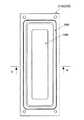
図1は、本発明の第一の実施形態に係る平面型スピーカユニットの平面図である。図2は、本発明の第一の実施形態に係る平面型スピーカユニットの側面図である。図3は、本発明の第一の実施形態に係る平面型スピーカユニットの底面図である。図4は、本発明の第一の実施形態に係る平面型スピーカユニットの正面図である。図5は、本発明の第一の実施形態に係る平面型スピーカユニットのA−A線断面図である。図6は、本発明の第一の実施形態に係る平面型スピーカユニットの部分断面図である。図7は、本発明の第一の実施形態に係る平面型スピーカユニットのB−B線断面図である。First, the engaging planar speaker unit according to the first embodiment of the present invention will be described with reference to the drawings. FIG. 1 is a plan view of the planar speaker unit according to the first embodiment of the present invention. FIG. 2 is a side view of the flat speaker unit according to the first embodiment of the present invention. FIG. 3 is a bottom view of the flat speaker unit according to the first embodiment of the present invention. FIG. 4 is a front view of the flat speaker unit according to the first embodiment of the present invention. FIG. 5 is a cross-sectional view taken along line AA of the flat speaker unit according to the first embodiment of the present invention. FIG. 6 is a partial cross-sectional view of the flat speaker unit according to the first embodiment of the present invention. FIG. 7 is a cross-sectional view taken along line B-B of the flat speaker unit according to the first embodiment of the present invention.
平面型スピーカユニットは、音響の放射面が平面であるスピーカのユニットである。
平面型スピーカユニットは、振動板100とフレーム200とエッジ300とボイスコイル式アクチエータ400とで構成される。
平面型スピーカユニットは、振動板100とフレーム200とエッジ300と複数のボイスコイル式アクチエータ400とで構成されてっもよい。
平面型スピーカユニットは、振動板100とフレーム200とエッジ300と複数のボイスコイル式アクチエータ400とカバーフレーム500とで構成されてもよい。The flat speaker unit is a speaker unit having a flat acoustic radiation surface.
The flat speaker unit includes a
The flat speaker unit may be composed of the
The planar speaker unit may include the
振動板100は、平面状の音響の放射面をもつ板状部材である。
振動板100は、複数の直線Lと複数の屈曲線Qとが交互に繋がってできた輪郭を形成する外周部である振動板外周部を持つ平板でできている。
屈曲線Qは、折線または曲線のうちの一方またはそれらの組み合わされた線である。
振動板100は、振動板表板101と振動板本体102と振動板裏板103とで構成される。
振動板表板101は、振動板100の表面を形成する板材であり、振動板本体102の表側に接着される。
振動板本体102は、所定の厚みをもつ板材である。
振動板裏板193は、振動板100の裏面を形成する板材であり、振動板本体102の裏側に接着される。The
The
The bending line Q is one of a broken line or a curved line or a combination thereof.
The
The
The diaphragm
The diaphragm back plate 193 is a plate material that forms the back surface of the
フレーム200は、平面型スピーカユニットの主構造体である。
フレーム200は、後述するボイスコイル式アクチエータ400を支持する。
フレーム200は、複数の直線と複数の屈曲線とが交互に繋がった輪郭を形成する内周部であるフレーム内周部でできた開口部であるフレーム開口部Oを設けられる。
フレーム200は、サブフレーム210とメインフレーム220とで構成されてもよい。
例えば、サブフレーム210は、フレーム開口部Oを設けられる。
例えば、メインフレーム220は、サブフレーム210を固定しボイスコイル式アクチエータを支持する。
サブフレーム210の弾性率がメインフレーム220の弾性率より小さくてもよい。
例えば、サブフレームの材質が樹脂であって、メインフレームの材質が金属である。
サブフレーム210が、板状部材であってもよい。
サブフレーム210は、エッジ外周部を固着する面を設けられる。
サブフレーム210は、表面と裏面とにエッジ外周部を固着する面を設けられる。
サブフレーム210は、板状部材の面から一段の段差を設けてエッジ内周部を固着する面を設けられてもよい。The
The
The
The
For example, the
For example, the
The elastic modulus of the
For example, the material of the subframe is resin, and the material of the main frame is metal.
The
The
The
The
振動板外周部とフレーム内周部とが接触しない様に振動板がフレーム開口部に嵌まる。
振動板外周部の屈曲線とフレーム内周部の屈曲線との1対の端部に挟まれた端部を除く箇所の隙間が振動板外周部の直線とフレーム内周部の直線との隙間より広い。
振動板外周部の直線とフレーム内周部の直線との隙間が一定の幅寸法をもち、振動板外周部の屈曲線とフレーム内周部の屈曲線との隙間が屈曲線の1対の端部から中間部に移動するにつれて大きくなる様に変化する幅寸法をもっていてもよい。The diaphragm fits into the frame opening so that the outer peripheral part of the diaphragm and the inner peripheral part of the frame do not contact each other.
The gap between the bending edge of the diaphragm outer peripheral part and the bending line of the inner peripheral part of the frame excluding the ends sandwiched between the pair of end parts is the clearance between the straight line of the outer peripheral part of the diaphragm and the straight line of the inner peripheral part of the frame Wider.
The gap between the straight line at the outer peripheral part of the diaphragm and the straight line at the inner peripheral part of the frame has a constant width, and the gap between the bent line at the outer peripheral part of the diaphragm and the bent line at the inner peripheral part of the frame is a pair of ends of the bent line. You may have the width dimension which changes so that it may become large as it moves to a middle part from a part.
屈曲線が一定の曲率半径をもつ曲線であり、フレーム内周部の屈曲線がフレーム内周部の直線に滑らかに繋がり、振動板外周部の屈曲線が振動板外周部の直線に滑らかに繋がり、振動板外周部の屈曲線の曲率中心がフレーム内周部の屈曲線の曲率中心より内側に位置してもよい。
振動板外周部の屈曲線の曲率半径R2とフレーム内周部の屈曲線の曲率半径R1とが略一致してもよい。The bend line is a curve with a certain radius of curvature, the bend line at the inner periphery of the frame is smoothly connected to the straight line at the inner periphery of the frame, and the bend line at the outer periphery of the diaphragm is smoothly connected to the straight line at the outer periphery of the diaphragm In addition, the center of curvature of the bending line on the outer peripheral part of the diaphragm may be located inside the center of curvature of the bending line on the inner peripheral part of the frame.
The curvature radius R2 of the bending line of the outer peripheral part of the diaphragm and the curvature radius R1 of the bending line of the inner peripheral part of the frame may substantially coincide.
エッジ300は、外周部であるエッジ外周部と内周部であるエッジ内周部とをもつ環状の弾性部材であって、エッジ外周部をフレーム内周部に固着され、エッジ内周部を振動板外周部に固着される。
エッジ300は、エッジ外周部301とエッジ湾曲部302とエッジ内周部303とを持つ弾性部材であってもよい。
エッジ外周部301は、所定の厚みで形成される断面を持つ。
エッジ湾曲部302は、面外に湾曲する断面を持つ。
例えば、エッジ湾曲部302は、所定の厚みを形成し表側に湾曲する断面を持つ。
エッジ内周部303は、所定の厚みを形成される断面を持つ。The
The
The edge outer
The
For example, the
The edge inner
エッジ300がメインフレーム220に固着しない様に、サブフレーム210がメインフレーム220に固定されてもよい。
エッジ300がメインフレーム220に接触しない様に、サブフレーム210がメインフレーム220に固定されてもよい。The
The
エッジ300は、表側エッジ310と裏側エッジ320とで構成されてもよい。
表側エッジ310は、エッジ外周部301とエッジ湾曲部302とエッジ内周部303とを持つ弾性部材であってもよい。
表側エッジ310は、エッジ外周部をフレーム内周部の表面に固着され、エッジ内周部を振動板外周部の表面に固着される。
裏側エッジ320は、エッジ外周部301とエッジ湾曲部302とエッジ内周部303とを持つ弾性部材である。
裏側エッジ320は、エッジ外周部をフレーム内周部の裏面に固着され、エッジ内周部を振動板外周部の裏面に固着される。
エッジ外周部301は、所定の厚みで形成される断面を持つ。
エッジ湾曲部302は、面外に湾曲する断面を持つ。
表側エッジ310のエッジ湾曲部302は、所定の厚みを形成し表側に湾曲する断面を持つ。
裏側エッジ320のエッジ湾曲部302は、所定の厚みを形成し裏側に湾曲する断面を持つ。
エッジ内周部303は、所定の厚みを形成される断面を持つ。The
The
The
The
The
The edge outer
The
The
The edge curved
The edge inner
表側エッジ310と裏側エッジ320とがメインフレーム220に固着しない様に、サブフレーム210がメインフレーム220に固定されてもよい。
表側エッジ310と裏側エッジ320とがメインフレーム220に接触しない様に、サブフレーム210がメインフレーム220に固定されてもよい。The
The
ボイスコイル式アクチエータ400は、フレーム200に支持され振動板100を面外振動する様に駆動するものである。
ボイスコイル式アクチエータ400は、メインフレーム220に支持され振動板100を面外振動する様に駆動するものであってもよい。
ボイスコイル式アクチエータ400は、ボイスコイルボビン410とボイスコイル420とヨーク530とマグネット540とポールピース550と補助マグネット560とで構成される。
ボイスコイルボビン410は、振動板に固定される。
例えば、ボイスコイルボビン410は、筒状の形状をする部材であり、一端を振動板100に固定される。
例えば、ボイスコイルボビン410は、円筒状の形状をする部材であり、一端を振動板100の裏面に固定される。
ボイスコイル420は、ボイスコイルボビンに巻きかけられた電線である。The
The
The
For example, the
For example, the
The
ヨーク430は、磁性材料でできメインフレーム220に固定される。
例えば、ヨーク430は、磁性材料ででき底を閉じた筒状の形状をする。
例えば、ヨーク430は、磁性材料ででき底を閉じた円筒状の形状をする。
マグネット440が、ヨーク430に固定される。
例えば、マグネット440は、柱状の形状をし、一端をヨーク430の底面に固着される。
例えば、マグネット440は、円柱状の形状をし、一端をヨーク430の底面に固着される。
ポールピース450は、磁性材料ででき該マグネットに固定される。
例えば、ポールピース450は、磁性材料でできた板状部材で、マグネット440の他端に固定される。
例えば、ポールピース450は、磁性材料でできた円板状部材で、マグネット440の他端に固定される。
ポールピース450の外周とヨーク430の内面とで形成される隙間が、磁気空隙を形成する。
ボイスコイル420が、磁気空間に位置する。
補助マグネット560は、ポールピース450に固定される。
交番電圧がボイスコイル420に印加されると、ボイスコイルボビン410が電磁気力により上下方向に力を作用され、振動板100を面外振動するように駆動する。The
For example, the
For example, the
A
For example, the
For example, the
The
For example, the
For example, the
A gap formed between the outer periphery of the
The
The auxiliary magnet 560 is fixed to the
When an alternating voltage is applied to the
カバーフレーム500は、フレーム200の表側を覆うフレームである。
カバーフレーム500は、サブフレーム210の外周部を覆う。
カバーフレーム500は、サブフレーム210の外周部と側面とを覆ってもよい。
カバーフレーム500は、サブフレーム210のフレーム開口部を除く表面と側面とを覆ってもよい。
前記サブフレームの弾性率が前記カバーフレームの弾性率より小さくてもよい。
例えば、サブフレーム210が樹脂製であって、カバーフレーム500が金属製である。
例えば、サブフレーム210とメインフレーム220とが樹脂製であり、カバーフレーム500が金属製である。
例えば、サブフレーム210が樹脂製であり、メインフレーム220とカバーフレーム500とが金属製である。
表側エッジ310と裏側エッジ320とがメインフレーム220とカバーフレーム500とに固着しない様に、カバーフレーム500とサブフレーム210とメインフレーム220とが固定されてもよい。
表側エッジ310と裏側エッジ320とがメインフレーム220とカバーフレーム500とに接触しない様に、カバーフレーム500とサブフレーム210とメインフレーム220とが固定されてもよい。The
The
The
The
The elastic modulus of the subframe may be smaller than the elastic modulus of the cover frame.
For example, the
For example, the
For example, the
The
The
振動板100の振動板外周部とフレーム開口部Oのフレーム内周部とで形成される隙間について詳述する。
図7は、本発明の第一の実施形態に係る平面型スピーカユニットの振動板100の振動板外周部とフレーム開口部Oのフレーム内周部とを図示する。
図7中で、理解の容易のために、エッジ300を二点破線で描いた。
振動板100の振動板外周部の輪郭が、4つの直線Lと4つの曲線Qとが交互に繋がってできる。
フレーム開口部Oのフレーム内周部の輪郭が、4つの直線Lと4つの曲線Qとが交互に繋がってできる。
振動板外周部とフレーム内周部とが接触しない様に振動板100がフレーム開口部Oに嵌まる。
振動板100の振動板外周部の輪郭の4つの直線Lが、フレーム開口部Oのフレーム内周部の輪郭の4つの直線Lに各々に対面する。
振動板100の振動板外周部の輪郭の4つの曲線Qが、フレーム開口部Oのフレーム内周部の輪郭の4つの曲線Qに各々に対面する。
振動板100の振動板外周部の輪郭の4つの曲線Qが、外側にふくらんだ曲率半径R2を持つ。
フレーム開口部Oの振動板内周部の輪郭の4つの曲線Qが、外側にふくらんだ曲率半径R1を持つ。
振動板100の振動板外周部の屈曲線の曲率中心がフレーム内周部の屈曲線の曲率中心より内側に位置する。
その結果、振動板外周部の直線とフレーム内周部の直線との隙間が一定の幅寸法をもち、振動板外周部の屈曲線とフレーム内周部の屈曲線との隙間が屈曲線の1対の端部から中間部に移動するにつれて大きくなる様に変化する幅寸法をもつ。The gap formed between the outer peripheral part of the
FIG. 7 illustrates the diaphragm outer periphery of the
In FIG. 7, for easy understanding, the
The contour of the outer peripheral portion of the
The outline of the inner periphery of the frame opening O is formed by alternately connecting four straight lines L and four curved lines Q.
The
The four straight lines L of the contour of the diaphragm outer periphery of the
Four curves Q of the contour of the diaphragm outer periphery of the
The four curves Q of the outline of the diaphragm outer periphery of the
The four curves Q of the outline of the diaphragm inner periphery of the frame opening O have a radius of curvature R1 that bulges outward.
The center of curvature of the bend line at the outer periphery of the
As a result, the gap between the straight line of the diaphragm outer peripheral part and the straight line of the frame inner peripheral part has a constant width dimension, and the gap between the bending line of the diaphragm outer peripheral part and the bending line of the frame inner peripheral part is one of the bending lines. It has a width that changes to increase as it moves from the end of the pair to the middle.
次に、本発明の第二の実施形態にかかる平面型スピーカユニットを、図を基に、説明する。
図8は、本発明の第二の実施形態に係る平面型スピーカユニットのB−B線断面図である。Next, a flat speaker unit according to a second embodiment of the present invention will be described with reference to the drawings.
FIG. 8 is a cross-sectional view taken along line B-B of the flat speaker unit according to the second embodiment of the present invention.
平面型スピーカユニットは、音響の放射面が平面であるスピーカのユニットである。
平面型スピーカユニットは、振動板100とフレーム200とエッジ300とボイスコイル式アクチエータ400とで構成される。
平面型スピーカユニットは、振動板100とフレーム200とエッジ300とボイスコイル式アクチエータ400とカバーフレーム500で構成されてもよい。
振動板100の外周部とフレーム開口部Oと内周部とで形成される隙間を除く構造は、第一の実施形態にかかる平面型スピーカユニットのものと同じなので説明を省略する。The flat speaker unit is a speaker unit having a flat acoustic radiation surface.
The flat speaker unit includes a
The planar speaker unit may include the
Since the structure excluding the gap formed by the outer peripheral portion of the
振動板100の外周部とフレーム開口部Oの内周部とで形成される隙間について詳述する。
図8は、本発明の第二の実施形態に係る平面型スピーカユニットの振動板100の振動板外周部とフレーム開口部Oのフレーム内周部とを図示する。
図8中で、理解の容易のために、エッジ300を二点破線で描いた。
振動板100の振動板外周部の輪郭が、4つの直線Lと4つの折線Qとが交互に繋がってできる。
フレーム開口部Oのフレーム内周部の輪郭が、4つの直線Lと4つの折線Qとが交互に繋がってできる。
振動板外周部とフレーム内周部とが接触しない様に振動板がフレーム開口部Oに嵌まる。
振動板100の振動板外周部の輪郭の4つの直線Lが、フレーム開口部Oのフレーム内周部の輪郭の4つの直線Lに各々に対面する。
振動板100の振動板外周部の輪郭の4つの折線Qが、フレーム開口部Oのフレーム内周部の輪郭の4つの折線Qに各々に対面する。
その結果、振動板外周部の直線とフレーム内周部の直線との隙間が一定の幅寸法をもち、振動板外周部の屈曲線とフレーム内周部の屈曲線との隙間が屈曲線の1対の端部から中間部に移動するにつれて大きくなる様に変化する幅寸法をもつ。A gap formed between the outer periphery of the
FIG. 8 illustrates the diaphragm outer peripheral portion of the
In FIG. 8, the
The outline of the outer peripheral part of the
The outline of the inner periphery of the frame opening O is formed by alternately connecting four straight lines L and four folding lines Q.
The diaphragm fits into the frame opening O so that the outer peripheral part of the diaphragm and the inner peripheral part of the frame do not contact each other.
The four straight lines L of the contour of the diaphragm outer periphery of the
The four fold lines Q of the contour of the diaphragm outer periphery of the
As a result, the gap between the straight line of the diaphragm outer peripheral part and the straight line of the frame inner peripheral part has a constant width dimension, and the gap between the bending line of the diaphragm outer peripheral part and the bending line of the frame inner peripheral part is one of the bending lines. It has a width that changes to increase as it moves from the end of the pair to the middle.
次に、本発明の第三の実施形態にかかる平面型スピーカユニットを、図を基に、説明する。
図9は、本発明の第三の実施形態に係る平面型スピーカユニットのB−B線断面図である。Next, a flat speaker unit according to a third embodiment of the present invention will be described with reference to the drawings.
FIG. 9 is a cross-sectional view taken along line BB of the flat speaker unit according to the third embodiment of the present invention.
平面型スピーカユニットは、音響の放射面が平面であるスピーカのユニットである。
平面型スピーカユニットは、振動板100とフレーム200とエッジ300とボイスコイル式アクチエータ400とで構成される。
平面型スピーカユニットは、振動板100とフレーム200とエッジ300とボイスコイル式アクチエータ400とカバーフレーム500で構成されてもよい。
振動板100の振動板外周部とフレーム開口部Oとフレーム内周部とで形成される隙間を除く構造は、第一の実施形態にかかる平面型スピーカユニットのものと同じなので説明を省略する。The flat speaker unit is a speaker unit having a flat acoustic radiation surface.
The flat speaker unit includes a
The planar speaker unit may include the
Since the structure excluding the gap formed by the diaphragm outer peripheral portion, the frame opening O and the frame inner peripheral portion of the
振動板100の振動板外周部とフレーム開口部Oのフレーム内周部とで形成される隙間について詳述する。
図7は、本発明の第一の実施形態に係る平面型スピーカユニットの振動板100の外周部とフレーム開口部Oと内周部とを図示する。
図7中で、理解の容易のために、エッジ300を二点破線で描いた。
振動板100の振動板外周部の輪郭が、4つの直線Lと4つの曲線Qとが交互に繋がってできる。
フレーム開口部Oのフレーム内周部の輪郭が、4つの直線Lと4つの曲線Qとが交互に繋がってできる。
振動板外周部とフレーム内周部とが接触しない様に振動板100がフレーム開口部Oに嵌まる。
振動板100の振動板外周部の輪郭の4つの直線Lが、フレーム開口部Oのフレーム内周部の輪郭の4つの直線Lに各々に対面する。
振動板100の振動板外周部の輪郭の4つの曲線Qが、フレーム開口部Oのフレーム内周部の輪郭の4つの曲線Qに各々に対面する。
振動板100の振動板外周部の輪郭の4つの曲線Qが、内側にふくらんだ曲率半径R2を持つ。
フレーム開口部Oのフレーム内周部の輪郭の4つの曲線Qが、外側にふくらんだ曲率半径R1を持つ。
その結果、振動板外周部の直線とフレーム内周部の直線との隙間が一定の幅寸法をもち、振動板外周部の屈曲線とフレーム内周部の屈曲線との隙間が屈曲線の1対の端部から中間部に移動するにつれて大きくなる様に変化する幅寸法をもつ。The gap formed between the outer peripheral part of the
FIG. 7 illustrates the outer periphery, the frame opening O, and the inner periphery of the
In FIG. 7, for easy understanding, the
The contour of the outer peripheral portion of the
The outline of the inner periphery of the frame opening O is formed by alternately connecting four straight lines L and four curved lines Q.
The
The four straight lines L of the contour of the diaphragm outer periphery of the
Four curves Q of the contour of the diaphragm outer periphery of the
The four curves Q of the contour of the diaphragm outer periphery of the
The four curves Q of the outline of the frame inner periphery of the frame opening O have a curvature radius R1 bulging outward.
As a result, the gap between the straight line of the diaphragm outer peripheral part and the straight line of the frame inner peripheral part has a constant width dimension, and the gap between the bending line of the diaphragm outer peripheral part and the bending line of the frame inner peripheral part is one of the bending lines. It has a width that changes to increase as it moves from the end of the pair to the middle.
上述のとおり、本発明の実施実施形態に係る平面型スピーカユニットを用いれば、以下の効果を有する。
フレーム200に設けられるフレーム開口部Oに嵌まる振動板100がエッジ300に支えられ、フレーム200に支持されたボイスコイル式アクチエータ400が振動板を駆動し、振動板100の振動板外周部の輪郭がN個の直線とN個の屈曲線とを交互に繋げたものであり、フレーム開口部のフレーム内周部がN個の直線とN個の屈曲線とを交互に繋げたものであり、振動板外周部とフレーム開口部との屈曲線の隙間が振動板外周部とフレーム開口部との直線の隙間より広くなる様にしたので、直線でのエッジの曲げ剛性と屈曲線でのエッジの曲げ剛性とを近似したものにしやすく、振動板100が均一に面外振動して、良好な音響特性をえる。
また、N個の直線とN個の直線との隙間が一定であり、屈曲線と屈曲線との隙間が1対の端部から中央部に移動するにしたがって大きくなるように変化するので、直線のエッジの曲げ剛性と屈曲線でのエッジの曲げ剛性とを近似したものにしやすく、振動板100が均一に面外振動して、良好な音響特性をえる。
また、屈曲線が一定の曲率半径をもつ曲線であり、振動板外周部の屈曲線の曲率中心がフレーム内周部の屈曲線の曲率中心より内側に位置する様にしたので、曲線と曲線との隙間が直線に繋がる端部から中央部に移動するにしたがってなだらかに大きくなるように変化する。
また、ボイスコイル式アクチエータ400を支持するメインフレーム220がフレーム開口部を設けられるサブフレーム210を固定し、サブフレーム210の弾性率がメインフレーム220の弾性率より小さい様にしたので、ボイスコイル式アクチエータ400を支持する構造の剛性を高く維持し、振動板100を支持する構造の剛性を低く維持できる。
また、エッジ300が表側エッジ310と裏側エッジ320とで構成され、表側エッジ310が振動板100の表面を支持し、裏側エッジ320が振動板100の裏面を支持する様にしたので、エッジ300を構成する弾性部材の引っ張り剛性により、振動板の傾きを効率良く抑制できる。
また、ボイスコイル式アクチエータ400を支持するメインフレーム220がフレーム開口部を設けられるサブフレーム210を固定しエッジ300が表側エッジ310と裏側エッジ320とで構成され、表側エッジ310が振動板100の表面を支持し、裏側エッジ320が振動板100の裏面を支持する様にしたので、エッジ300を構成する弾性部材の引っ張り剛性により、振動板の傾きを効率良く抑制できる。
また、サブフレーム210の弾性率より大きな弾性率をもつカバーフレーム500がサブフレーム210の外周部と側面とを覆う様にしたので、スピーカユニット全体の剛性を高め、振動板100を支持する構造の剛性を低く維持できる。
また、サブフレーム210の弾性率より大きな弾性率をもつカバーフレーム500がサブフレーム210のフレーム開口部Oを除く表面と側面とを覆う様にしたので、スピーカユニット全体の剛性を高め、振動板100を支持する構造の剛性を低く維持できる。
また、ボイスコイル式アクチエータ400が、ボイスコイルボビン410とボイスコイル420とヨーク430とマグネット440とポールピース450と補助マグネット460とで構成され、ボイスコイル420が磁場から振動板100の表面に直交する力を作用される様にしたので、振動板100の傾きを抑制できる。As described above, the use of the planar speaker unit according to the embodiment of the present invention has the following effects.
The
Further, the gap between the N straight lines and the N straight lines is constant, and the gap between the bending line and the bending line changes so as to increase as it moves from the pair of end portions to the central portion. The bending rigidity of the edge and the bending rigidity of the edge at the bending line can be easily approximated, and the
In addition, the bend line is a curve having a constant radius of curvature, and the center of curvature of the bend line on the outer peripheral part of the diaphragm is positioned inside the center of curvature of the bend line on the inner peripheral part of the frame. The gap changes gradually so as to move from the end connected to the straight line to the center.
In addition, the
Further, the
Further, the
Further, since the
Further, since the
The
本発明は以上に述べた実施形態に限られるものではなく、発明の要旨を逸脱しない範囲で各種の変更が可能である。
ボイスコイル式アクチエータの構造を説明したが、これに限定されない。
また、振動板100の形状を4つの直線と4つの屈曲線が交互に繋がった輪郭をもつものであるとして説明したが、これに限定されない、例えば、振動板100の形状を3つ、または5つ以上の直線と3つまたは5つ以上の屈曲線が交互に繋がった輪郭をもつものとしてもよい。The present invention is not limited to the embodiments described above, and various modifications can be made without departing from the scope of the invention.
Although the structure of the voice coil actuator has been described, the structure is not limited to this.
Moreover, although the shape of the
O フレーム開口部
L 直線
Q 屈曲線
100 振動板
101 振動板表板
102 振動板本体
103 振動板裏板
200 フレーム
210 サブフレーム
220 メインフレーム
300 エッジ
301 エッジ外周部
302 エッジ湾曲部
303 エッジ内周部
310 表側エッジ
320 裏側エッジ
400 ボイスコイル式アクチエータ
410 ボイスコイルボビン
420 ボイスコイル
430 ヨーク
440 マグネット
450 ポールピース
460 補助マグネット
500 カバーフレームO Frame opening L Straight line
Claims (4)
Translated fromJapanese4つの直線と4つの屈曲線とが交互に繋がってできた輪郭を形成する外周部である振動板外周部を持ち表面が平面になった部材である振動板と、
4つの直線と4つの屈曲線とが交互に繋がった輪郭を形成する内周部であるフレーム内周部でできた開口部であるフレーム開口部を設けられるフレームと、
外周部であるエッジ外周部と内周部であるエッジ内周部とをもつ環状の弾性部材であって該エッジ外周部を前記フレーム内周部に固着され該エッジ内周部を前記振動板外周部に固着されるエッジと、
前記フレームに支持され前記振動板を面外振動する様に駆動するボイスコイル式アクチエータと、
を備え、
屈曲線が折線または曲線のうちの一方またはそれらの組み合わされた線であり、
前記振動板外周部と前記フレーム内周部とが接触しない様に前記振動板が前記フレーム開口部に嵌まり、
前記振動板外周部の屈曲線と前記フレーム内周部の屈曲線との1対の端部に挟まれた端部を除く箇所の隙間が前記振動板外周部の直線と前記フレーム内周部の直線との隙間より広く、
前記フレームが前記フレーム開口部を設けられるサブフレームと該サブフレームを固定し前記ボイスコイル式アクチエータを支持するメインフレームとを有し、
前記サブフレームが板状部材であって、
前記エッジは、中央が円弧状に湾曲し、該エッジ外周部を前記フレーム内周部の表面に固着され該エッジ内周部を前記振動板外周部の表面に固着される表側エッジと、中央が円弧状に湾曲し、該エッジ外周部を前記フレーム内周部の裏面に固着され該エッジ内周部を前記振動板外周部の裏面に固着される裏側エッジとを有し、
前記表側エッジと前記裏側エッジとが前記メインフレームに固着しない様に前記サブフレームがメインフレームに固定される、
ことを特徴とする平面型スピーカユニット。A flat speaker unit,
A diaphragm which is a member having a diaphragm outer peripheral part which is an outer peripheral part forming an outline formed by alternately connectingfour straight lines andfour bending lines;
A frame provided with a frame opening which is an opening made of a frame inner peripheral part which is an inner peripheral part forming an outline in whichfour straight lines andfour bent lines are alternately connected;
An annular elastic member having an outer periphery of an edge that is an outer periphery and an inner periphery of an edge that is an inner periphery, the outer periphery of the edge being fixed to the inner periphery of the frame, and the inner periphery of the edge being the outer periphery of the diaphragm An edge fixed to the part,
A voice coil actuator that is supported by the frame and drives the diaphragm to vibrate out of plane;
With
The bend line is one of a fold line or a curve or a combination thereof;
The diaphragm fits into the frame opening so that the outer periphery of the diaphragm and the inner periphery of the frame do not contact each other,
A gap between the bent portion of the diaphragm outer peripheral portion and a bent line of the frame inner peripheral portion excluding the ends sandwiched between the pair of end portions is a straight line between the diaphragm outer peripheral portion and the frame inner peripheral portion.widely than the gap between the straightline,
The frame includes a subframe in which the frame opening is provided, and a main frame that fixes the subframe and supports the voice coil actuator;
The subframe is a plate-shaped member,
The edge is curved in a circular arc shape at the center, the edge outer peripheral portion is fixed to the surface of the frame inner peripheral portion, and the edge inner peripheral portion is fixed to the surface of the diaphragm outer peripheral portion; Curved in an arc shape, the edge outer peripheral portion is fixed to the back surface of the frame inner peripheral portion, and the edge inner peripheral portion is fixed to the rear surface of the diaphragm outer peripheral portion, and a back side edge,
The subframe is fixed to the main frame so that the front side edge and the back side edge are not fixed to the main frame.
A planar speaker unit characterized by the above.
前記振動板外周部の屈曲線と前記フレーム内周部の屈曲線との隙間が屈曲線の1対の端部から中間部に移動するにつれて大きくなる様に変化する幅寸法をもつ、
ことを特徴とする請求項1に記載の平面型スピーカユニット。The gap between the straight line of the outer peripheral part of the diaphragm and the straight line of the inner peripheral part of the frame has a constant width dimension,
A width dimension that changes so that a gap between the bending line of the outer peripheral part of the diaphragm and the bending line of the inner peripheral part of the frame moves from a pair of ends of the bending line to an intermediate part;
The flat speaker unit according to claim 1.
前記フレーム内周部の屈曲線が前記フレーム内周部の直線に滑らかに繋がり、
前記振動板外周部の屈曲線が前記振動板外周部の直線に滑らかに繋がり、
前記振動板外周部の屈曲線の曲率中心が前記フレーム内周部の屈曲線の曲率中心より内側に位置する、
ことを特徴とする請求項2に記載の平面型スピーカユニット。The bend line is a curve with a certain radius of curvature,
The bent line of the inner periphery of the frame is smoothly connected to the straight line of the inner periphery of the frame,
The bending line of the outer periphery of the diaphragm is smoothly connected to the straight line of the outer periphery of the diaphragm,
The center of curvature of the bending line of the outer peripheral part of the diaphragm is located inside the center of curvature of the bending line of the inner peripheral part of the frame;
The flat speaker unit according to claim 2.
を備え、
前記サブフレームの弾性率が前記カバーフレームの弾性率より小さい、
ことを特徴とする請求項3に記載の平面型スピーカユニット。A cover frame that covers an outer peripheral portion of the subframe and a side surface of the subframe;
With
The elastic modulus of the subframe is smaller than the elastic modulus of the cover frame;
The flat speaker unit according to claim3 .
Priority Applications (2)
| Application Number | Priority Date | Filing Date | Title |
|---|---|---|---|
| JP2011029215AJP5702181B2 (en) | 2011-02-14 | 2011-02-14 | Flat speaker unit |
| PCT/JP2012/053224WO2012111588A1 (en) | 2011-02-14 | 2012-02-13 | Flat-type speaker unit |
Applications Claiming Priority (1)
| Application Number | Priority Date | Filing Date | Title |
|---|---|---|---|
| JP2011029215AJP5702181B2 (en) | 2011-02-14 | 2011-02-14 | Flat speaker unit |
Publications (2)
| Publication Number | Publication Date |
|---|---|
| JP2012169871A JP2012169871A (en) | 2012-09-06 |
| JP5702181B2true JP5702181B2 (en) | 2015-04-15 |
Family
ID=46672507
Family Applications (1)
| Application Number | Title | Priority Date | Filing Date |
|---|---|---|---|
| JP2011029215AExpired - Fee RelatedJP5702181B2 (en) | 2011-02-14 | 2011-02-14 | Flat speaker unit |
Country Status (2)
| Country | Link |
|---|---|
| JP (1) | JP5702181B2 (en) |
| WO (1) | WO2012111588A1 (en) |
Families Citing this family (6)
| Publication number | Priority date | Publication date | Assignee | Title |
|---|---|---|---|---|
| WO2014129975A1 (en)* | 2013-02-20 | 2014-08-28 | Singapore Health Services Pte Ltd | Identification of circulating microrna signatures for breast cancer detection |
| KR101413965B1 (en) | 2013-04-15 | 2014-07-04 | 에스텍 주식회사 | System speaker |
| WO2014208575A1 (en) | 2013-06-28 | 2014-12-31 | 日本電気株式会社 | Video monitoring system, video processing device, video processing method, and video processing program |
| KR101584651B1 (en) | 2013-09-13 | 2016-01-12 | 주식회사 진영지앤티 | Slim type speaker and method for manufacturing thereof |
| KR101609708B1 (en)* | 2015-01-15 | 2016-04-20 | 주식회사 엠소닉 | Speakers with a two-sided type edge |
| KR102346606B1 (en)* | 2020-12-29 | 2022-01-03 | 범진시엔엘 주식회사 | Dynamic speaker |
Family Cites Families (7)
| Publication number | Priority date | Publication date | Assignee | Title |
|---|---|---|---|---|
| JPS61121097U (en)* | 1985-01-17 | 1986-07-30 | ||
| JPH0720313B2 (en)* | 1985-03-18 | 1995-03-06 | 松下電器産業株式会社 | Speaker |
| JP3844074B2 (en)* | 2002-11-29 | 2006-11-08 | ホシデン株式会社 | Diaphragm for flat coil speaker and flat coil speaker using the same |
| JP2006050410A (en)* | 2004-08-06 | 2006-02-16 | Star Micronics Co Ltd | Electroacoustic transducer and manufacturing method therefor |
| US8090139B2 (en)* | 2005-06-29 | 2012-01-03 | Benjamin Reinecke | Diaphragm for an electroacoustic transducer, and electroacoustic transducer |
| JP2007096620A (en)* | 2005-09-28 | 2007-04-12 | Matsushita Electric Ind Co Ltd | Speaker and structure using the same |
| JP2009201005A (en)* | 2008-02-25 | 2009-09-03 | Onkyo Corp | Motor-driven type speaker |
- 2011
- 2011-02-14JPJP2011029215Apatent/JP5702181B2/ennot_activeExpired - Fee Related
- 2012
- 2012-02-13WOPCT/JP2012/053224patent/WO2012111588A1/enactiveApplication Filing
Also Published As
| Publication number | Publication date |
|---|---|
| WO2012111588A1 (en) | 2012-08-23 |
| JP2012169871A (en) | 2012-09-06 |
Similar Documents
| Publication | Publication Date | Title |
|---|---|---|
| JP5702181B2 (en) | Flat speaker unit | |
| CN111373765B (en) | Low Profile Speaker Unit | |
| KR102750853B1 (en) | Distributed transducer suspension cones (dtsc) | |
| US9743192B2 (en) | Speaker and vibration control unit | |
| WO2014199531A1 (en) | Speaker and edge structure for same | |
| RU2011142163A (en) | LOUDSPEAKER DEVICE | |
| JP2005159409A (en) | Diaphragm for speaker and speaker using the same | |
| JP2007535260A (en) | Diaphragm for loudspeaker with moving coil | |
| CN114745643B (en) | Sound-generating vibration device and electronic device | |
| JP5025824B2 (en) | Nested compound speaker drive unit | |
| KR101119495B1 (en) | Magnet plate and base frame structure of flat type speaker | |
| JP2018207265A (en) | Loudspeaker | |
| JP6188417B2 (en) | Hybrid speaker | |
| CN109076270A (en) | Speaker motor and suspension | |
| EP3038379A1 (en) | Electroacoustic transducer | |
| CN106303851A (en) | Loudspeaker structure | |
| US20140321692A1 (en) | Loudspeaker | |
| WO2021145209A1 (en) | Actuator | |
| KR102205854B1 (en) | Flat type speaker including asymmetric magnet structure and base frame | |
| CN103379415A (en) | Loudspeaker | |
| US11057713B2 (en) | Vibratable element for loudspeaker use and loudspeaker device | |
| JP2012034184A (en) | Speaker device | |
| US11297438B2 (en) | Electrodynamic acoustic transducer having a polygonal membrane with improved compliance | |
| JP2011101282A (en) | Speaker | |
| JP2009159009A (en) | Speaker |
Legal Events
| Date | Code | Title | Description |
|---|---|---|---|
| A711 | Notification of change in applicant | Free format text:JAPANESE INTERMEDIATE CODE: A711 Effective date:20120626 | |
| A621 | Written request for application examination | Free format text:JAPANESE INTERMEDIATE CODE: A621 Effective date:20140212 | |
| A131 | Notification of reasons for refusal | Free format text:JAPANESE INTERMEDIATE CODE: A131 Effective date:20140805 | |
| A521 | Written amendment | Free format text:JAPANESE INTERMEDIATE CODE: A523 Effective date:20141006 | |
| TRDD | Decision of grant or rejection written | ||
| A01 | Written decision to grant a patent or to grant a registration (utility model) | Free format text:JAPANESE INTERMEDIATE CODE: A01 Effective date:20150203 | |
| A61 | First payment of annual fees (during grant procedure) | Free format text:JAPANESE INTERMEDIATE CODE: A61 Effective date:20150219 | |
| R150 | Certificate of patent or registration of utility model | Ref document number:5702181 Country of ref document:JP Free format text:JAPANESE INTERMEDIATE CODE: R150 | |
| LAPS | Cancellation because of no payment of annual fees |