JP5701715B2 - Energy management device, power management system and program - Google Patents
Energy management device, power management system and programDownload PDFInfo
- Publication number
- JP5701715B2 JP5701715B2JP2011176935AJP2011176935AJP5701715B2JP 5701715 B2JP5701715 B2JP 5701715B2JP 2011176935 AJP2011176935 AJP 2011176935AJP 2011176935 AJP2011176935 AJP 2011176935AJP 5701715 B2JP5701715 B2JP 5701715B2
- Authority
- JP
- Japan
- Prior art keywords
- application
- network
- unit
- access
- management
- Prior art date
- Legal status (The legal status is an assumption and is not a legal conclusion. Google has not performed a legal analysis and makes no representation as to the accuracy of the status listed.)
- Active
Links
Images


Classifications
- H—ELECTRICITY
- H04—ELECTRIC COMMUNICATION TECHNIQUE
- H04L—TRANSMISSION OF DIGITAL INFORMATION, e.g. TELEGRAPHIC COMMUNICATION
- H04L63/00—Network architectures or network communication protocols for network security
- H04L63/20—Network architectures or network communication protocols for network security for managing network security; network security policies in general
- G—PHYSICS
- G06—COMPUTING OR CALCULATING; COUNTING
- G06F—ELECTRIC DIGITAL DATA PROCESSING
- G06F1/00—Details not covered by groups G06F3/00 - G06F13/00 and G06F21/00
- G06F1/26—Power supply means, e.g. regulation thereof
- G06F1/32—Means for saving power
- G06F1/3203—Power management, i.e. event-based initiation of a power-saving mode
- G—PHYSICS
- G06—COMPUTING OR CALCULATING; COUNTING
- G06F—ELECTRIC DIGITAL DATA PROCESSING
- G06F21/00—Security arrangements for protecting computers, components thereof, programs or data against unauthorised activity
- G06F21/60—Protecting data
- G06F21/62—Protecting access to data via a platform, e.g. using keys or access control rules
- G06F21/6218—Protecting access to data via a platform, e.g. using keys or access control rules to a system of files or objects, e.g. local or distributed file system or database
- G06F21/6272—Protecting access to data via a platform, e.g. using keys or access control rules to a system of files or objects, e.g. local or distributed file system or database by registering files or documents with a third party
- G—PHYSICS
- G06—COMPUTING OR CALCULATING; COUNTING
- G06F—ELECTRIC DIGITAL DATA PROCESSING
- G06F21/00—Security arrangements for protecting computers, components thereof, programs or data against unauthorised activity
- G06F21/70—Protecting specific internal or peripheral components, in which the protection of a component leads to protection of the entire computer
- G06F21/81—Protecting specific internal or peripheral components, in which the protection of a component leads to protection of the entire computer by operating on the power supply, e.g. enabling or disabling power-on, sleep or resume operations
- G—PHYSICS
- G06—COMPUTING OR CALCULATING; COUNTING
- G06F—ELECTRIC DIGITAL DATA PROCESSING
- G06F21/00—Security arrangements for protecting computers, components thereof, programs or data against unauthorised activity
- G06F21/70—Protecting specific internal or peripheral components, in which the protection of a component leads to protection of the entire computer
- G06F21/82—Protecting input, output or interconnection devices
- G06F21/85—Protecting input, output or interconnection devices interconnection devices, e.g. bus-connected or in-line devices
- G—PHYSICS
- G06—COMPUTING OR CALCULATING; COUNTING
- G06Q—INFORMATION AND COMMUNICATION TECHNOLOGY [ICT] SPECIALLY ADAPTED FOR ADMINISTRATIVE, COMMERCIAL, FINANCIAL, MANAGERIAL OR SUPERVISORY PURPOSES; SYSTEMS OR METHODS SPECIALLY ADAPTED FOR ADMINISTRATIVE, COMMERCIAL, FINANCIAL, MANAGERIAL OR SUPERVISORY PURPOSES, NOT OTHERWISE PROVIDED FOR
- G06Q10/00—Administration; Management
- G06Q10/04—Forecasting or optimisation specially adapted for administrative or management purposes, e.g. linear programming or "cutting stock problem"
- G—PHYSICS
- G06—COMPUTING OR CALCULATING; COUNTING
- G06Q—INFORMATION AND COMMUNICATION TECHNOLOGY [ICT] SPECIALLY ADAPTED FOR ADMINISTRATIVE, COMMERCIAL, FINANCIAL, MANAGERIAL OR SUPERVISORY PURPOSES; SYSTEMS OR METHODS SPECIALLY ADAPTED FOR ADMINISTRATIVE, COMMERCIAL, FINANCIAL, MANAGERIAL OR SUPERVISORY PURPOSES, NOT OTHERWISE PROVIDED FOR
- G06Q50/00—Information and communication technology [ICT] specially adapted for implementation of business processes of specific business sectors, e.g. utilities or tourism
- G06Q50/06—Energy or water supply
- G—PHYSICS
- G06—COMPUTING OR CALCULATING; COUNTING
- G06F—ELECTRIC DIGITAL DATA PROCESSING
- G06F2221/00—Indexing scheme relating to security arrangements for protecting computers, components thereof, programs or data against unauthorised activity
- G06F2221/21—Indexing scheme relating to G06F21/00 and subgroups addressing additional information or applications relating to security arrangements for protecting computers, components thereof, programs or data against unauthorised activity
- G06F2221/2129—Authenticate client device independently of the user
- G—PHYSICS
- G06—COMPUTING OR CALCULATING; COUNTING
- G06F—ELECTRIC DIGITAL DATA PROCESSING
- G06F2221/00—Indexing scheme relating to security arrangements for protecting computers, components thereof, programs or data against unauthorised activity
- G06F2221/21—Indexing scheme relating to G06F21/00 and subgroups addressing additional information or applications relating to security arrangements for protecting computers, components thereof, programs or data against unauthorised activity
- G06F2221/2141—Access rights, e.g. capability lists, access control lists, access tables, access matrices
- Y—GENERAL TAGGING OF NEW TECHNOLOGICAL DEVELOPMENTS; GENERAL TAGGING OF CROSS-SECTIONAL TECHNOLOGIES SPANNING OVER SEVERAL SECTIONS OF THE IPC; TECHNICAL SUBJECTS COVERED BY FORMER USPC CROSS-REFERENCE ART COLLECTIONS [XRACs] AND DIGESTS
- Y04—INFORMATION OR COMMUNICATION TECHNOLOGIES HAVING AN IMPACT ON OTHER TECHNOLOGY AREAS
- Y04S—SYSTEMS INTEGRATING TECHNOLOGIES RELATED TO POWER NETWORK OPERATION, COMMUNICATION OR INFORMATION TECHNOLOGIES FOR IMPROVING THE ELECTRICAL POWER GENERATION, TRANSMISSION, DISTRIBUTION, MANAGEMENT OR USAGE, i.e. SMART GRIDS
- Y04S40/00—Systems for electrical power generation, transmission, distribution or end-user application management characterised by the use of communication or information technologies, or communication or information technology specific aspects supporting them
- Y04S40/20—Information technology specific aspects, e.g. CAD, simulation, modelling, system security
Landscapes
- Engineering & Computer Science (AREA)
- Theoretical Computer Science (AREA)
- Computer Hardware Design (AREA)
- General Physics & Mathematics (AREA)
- Physics & Mathematics (AREA)
- Business, Economics & Management (AREA)
- Computer Security & Cryptography (AREA)
- General Engineering & Computer Science (AREA)
- Economics (AREA)
- Health & Medical Sciences (AREA)
- Software Systems (AREA)
- Strategic Management (AREA)
- Human Resources & Organizations (AREA)
- General Health & Medical Sciences (AREA)
- Marketing (AREA)
- Databases & Information Systems (AREA)
- Tourism & Hospitality (AREA)
- Bioethics (AREA)
- General Business, Economics & Management (AREA)
- Entrepreneurship & Innovation (AREA)
- Development Economics (AREA)
- Signal Processing (AREA)
- Operations Research (AREA)
- Computing Systems (AREA)
- Quality & Reliability (AREA)
- Game Theory and Decision Science (AREA)
- Computer Networks & Wireless Communication (AREA)
- Public Health (AREA)
- Water Supply & Treatment (AREA)
- Primary Health Care (AREA)
- Storage Device Security (AREA)
- Data Exchanges In Wide-Area Networks (AREA)
- Computer And Data Communications (AREA)
Description
Translated fromJapanese本発明の実施形態は、電力系統から供給される電力と、宅内で消費あるいは発生する電力とを管理するエネルギー管理装置および電力管理システムに関する。 Embodiments described herein relate generally to an energy management apparatus and a power management system that manage power supplied from a power system and power consumed or generated in a home.
原子力や火力などの枯渇性エネルギーと太陽光や風力などの再生可能エネルギーとを併用して電力品質の安定化を図るために、次世代電力網(スマートグリッド)を構築する計画が進められている。 In order to stabilize power quality by using exhaustive energy such as nuclear power and thermal power and renewable energy such as solar power and wind power, a plan to construct a next-generation power network (smart grid) is underway.
次世代電力網では、メンテナンスや電力需要の予測処理のために、EMS(Energy Management System)などの系統機器がインターネットに接続されることになる。ところが、インターネットは、コンピュータウイルスや情報漏洩、不正アクセスなどの脅威に晒されており、EMS等の系統機器をインターネットに接続すると、情報セキュリティ上の問題が生じるおそれがある。 In the next-generation power network, system devices such as EMS (Energy Management System) are connected to the Internet for maintenance and prediction of power demand. However, the Internet is exposed to threats such as computer viruses, information leakage, and unauthorized access, and there is a risk of problems in information security when system devices such as EMS are connected to the Internet.
例えば、従来の不正アクセス対策技術としては、ネットワークやEMS上に侵入検知システム(Intrusion Detection System: IDS)を設置したり、脆弱性(セキュリティ上の欠陥)に対処するためのパッチを定期的に適用するといった手法が一般的である。しかしながら、系統機器、特にEMSの場合、Webサーバなどの従来のサーバ機器とは異なり、系統ネットワークを介してRTU(Remote Terminal Unit)などの機器から発電量などの情報を収集し、等時間間隔で定期的に発電命令などの信号を伝送する必要があり、レイテンシの制約が生じることが考えられる。このため、不正アクセスの検出のような処理負荷の高い煩雑な処理を系統機器で実行するのは現実的ではない。系統機器ではインターネットからの不正アクセスを防止しつつ本来の電力制御の処理に影響を与えない不正アクセス防止機能を備えていることが望ましい。 For example, as conventional unauthorized access countermeasure technology, an intrusion detection system (Intrusion Detection System: IDS) is installed on the network or EMS, and patches are regularly applied to deal with vulnerabilities (security flaws). The technique of doing is common. However, in the case of grid devices, especially EMS, unlike conventional server devices such as Web servers, information such as the amount of power generation is collected from devices such as RTU (Remote Terminal Unit) via the grid network at regular intervals. It is necessary to periodically transmit a signal such as a power generation command, which may cause latency restrictions. For this reason, it is not realistic to execute complicated processing with a high processing load such as detection of unauthorized access on the system device. It is desirable for the system equipment to have an unauthorized access prevention function that prevents unauthorized access from the Internet and does not affect the original power control process.
本発明の一実施形態は、本来の電力制御の処理に影響を与えずにネットワークからの不正アクセスを防止可能なエネルギー管理装置および電力管理システムを提供することにある。 One embodiment of the present invention is to provide an energy management apparatus and a power management system that can prevent unauthorized access from a network without affecting the original power control process.
本実施形態に係るエネルギー管理装置は、電力管理用のアプリケーションを含む少なくとも一つ以上のアプリケーションが記憶されたアプリケーション記憶部と、アプリケーション記憶部に記憶されたアプリケーションを実行するアプリケーション実行部と、複数のネットワークのそれぞれに対応して設けられる複数のネットワークインタフェース部と、個々のアプリケーションごとに、複数のネットワークインタフェース部のそれぞれに対するアクセスを許可するか否かを設定するポリシー設定部と、ポリシー設定部が設定する個々のアプリケーションごとに、アプリケーションの識別情報と、複数のネットワークインタフェース部のそれぞれに対するアクセスを許可するか否かを示すアクセス可否情報とを記憶するポリシー記憶部と、ネットワークアドレスと、複数のネットワークインタフェース部のそれぞれとの対応関係を管理し、アプリケーション実行部が実行するアプリケーションが利用するネットワークインタフェース部を特定するI/F管理部と、アプリケーション実行部が実行するアプリケーションが利用するネットワークインタフェース部に対するアクセスが許可されているか否かをポリシー記憶部に記憶されたアクセス可否情報に基づいて判断するアクセス制御部と、を備える。 The energy management apparatus according to the present embodiment includes an application storage unit that stores at least one application including an application for power management, an application execution unit that executes an application stored in the application storage unit, and a plurality of applications Set by the policy setting unit and the policy setting unit that sets whether or not to allow access to each of the plurality of network interface units for each application. A policy storage unit that stores application identification information and access permission information indicating whether or not to permit access to each of the plurality of network interface units; An I / F management unit that manages a correspondence relationship between a network address and each of a plurality of network interface units and identifies a network interface unit used by an application executed by the application execution unit, and an application executed by the application execution unit An access control unit that determines whether or not access to the network interface unit to be used is permitted based on access permission information stored in the policy storage unit.
また、本発明の一実施形態は、電力管理用のアプリケーションを含む少なくとも一つ以上のアプリケーションが記憶されたアプリケーション記憶部と、アプリケーション記憶部に記憶されたアプリケーションを実行するアプリケーション実行部と、公衆ネットワークおよび専用ネットワークを含む複数のネットワークのそれぞれに対応して設けられる複数のネットワークインタフェース部と、個々のアプリケーションごとに、複数のネットワークインタフェース部のそれぞれに対するアクセスを許可するか否かを設定するポリシー設定部と、ポリシー設定部が設定する個々のアプリケーションごとに、アプリケーションの識別情報と、複数のネットワークインタフェース部のそれぞれに対するアクセスを許可するか否かを示すアクセス可否情報とを記憶するポリシー記憶部と、アプリケーション実行部が実行するアプリケーションが利用するネットワークインタフェース部に対するアクセスが許可されているか否かをポリシー記憶部に記憶されたアクセス可否情報に基づいて判断するアクセス制御部と、アプリケーション実行部が現在実行中のアプリケーションについての識別情報と複数のネットワークインタフェース部に対するアクセス可否情報とを登録した管理テーブルを作成して、現在実行中のアプリケーションを管理するアプリケーション実行管理部と、を備え、アプリケーション実行管理部は、アプリケーション実行部が実行するアプリケーションが専用ネットワークに対するアクセスを許可されているか否かを前記ポリシー記憶部に記憶されたアクセス可否情報に基づいて判定し、許可されていれば、管理テーブル中の該アプリケーションのアクセス可否情報を許可モードに設定し、許可されていなければ禁止モードに設定する開始時モード設定部と、アプリケーションの終了時に、該アプリケーションが専用ネットワークに対するアクセスが禁止されているか否かをポリシー記憶部に記憶されたアクセス可否情報に基づいて判定し、禁止されていなければ、そのまま終了し、禁止されていれば、他のアプリケーションが前記管理テーブルに登録されているか否かを検出し、登録されていれば実行中のすべてのアプリケーションについて専用ネットワークに対するアクセスを禁止する前記禁止モードに設定し、登録されていなければ実行中のすべてのアプリケーションについて前記専用ネットワークに対するアクセスを許可する許可モードに設定する終了時モード設定部と、終了時モード設定部でモード設定を行なった後に、終了したアプリケーションに関する登録情報を管理テーブルから削除する登録削除部と、を有する。 In addition, an embodiment of the present invention includes an application storage unit that stores at least one application including an application for power management, an application execution unit that executes an application stored in the application storage unit, and a public network And a plurality of network interface units provided corresponding to each of a plurality of networks including a dedicated network, and a policy setting unit for setting whether to allow access to each of the plurality of network interface units for each individual application And for each application set by the policy setting unit, application identification information and access permission information indicating whether or not to allow access to each of the plurality of network interface units. And an access control unit that determines whether or not access to a network interface unit used by an application executed by the application execution unit is permitted based on access permission information stored in the policy storage unit An application execution management unit that creates a management table in which identification information about an application that is currently being executed by the application execution unit and information on whether or not to access a plurality of network interface units is registered, and an application that is currently executing, And the application execution management unit determines whether or not an application executed by the application execution unit is permitted to access the dedicated network based on the access permission information stored in the policy storage unit. If it is permitted, the access permission information of the application in the management table is set to the permission mode, and if not permitted, the prohibition mode is set. It is determined whether or not the application is prohibited from accessing the dedicated network based on the access permission information stored in the policy storage unit. If not prohibited, the process is terminated. It is detected whether or not it is registered in the management table, and if it is registered, it is set to the prohibit mode for prohibiting access to the dedicated network for all running applications. About the application to the dedicated network An end-time mode setting unit that sets a permission mode for permitting access; and a registration deletion unit that deletes registration information about the terminated application from the management table after mode setting is performed by the end-time mode setting unit.
(第1の実施形態)
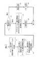
図1は第1の実施形態に係るエネルギー管理装置(EMS)を備えた電力管理システム1の概略構成を示すブロック図である。図1の電力管理システム1は、電力系統管理装置2と、この電力系統管理装置2とインターネット3を介して通信を行う宅内電力管理装置4と、電力系統管理装置2とインターネット3を介して通信を行うメンテナンス用管理端末5および天気予報サーバ6とを備えている。(First embodiment)
FIG. 1 is a block diagram illustrating a schematic configuration of a
電力系統管理装置2は、EMS(エネルギー管理装置)10と、MDMS(Meter Data Management System)11と、コンセントレータ12と、RTU(Remote Terminal Unit)13と、分散電源14と、蓄電装置15と、送配電制御装置16とを有する。電力系統管理装置2内のEMS10、MDMS11、RTU13は内部ネットワーク17に接続されている。この内部ネットワーク17は、系統ネットワークあるいは専用ネットワークとも呼ばれる。 The power
宅内電力管理装置4は、各家庭ごとに設けられるものであり、スマートメータ18とHEMS19(Home Energy Management System)とを有する。各家庭で太陽電池パネル等により発生した余剰電力を電力系統側に供給する場合には、その制御を行う装置を宅内電力管理装置4内に設けてもよい。 The in-home
スマートメータ18は、インターネット3を介して、電力系統管理装置2内のコンセントレータ12と呼ばれる中継器によって数台ごとにまとめられ、内部ネットワーク17を介してMDMS11と通信する。MDMS11は、各家庭のスマートメータ18から一定の時間間隔で電力使用量を受信して記憶する。MDMS11はインターネット3を介してHEMS19と接続されており、電力の需要抑制命令や発電命令などをHEMS19に送信する。 The
EMS10は、MDMS11に集約された複数の家庭の電力使用量、あるいは電力系統管理装置2内に設置されたセンサ(不図示)からの情報に基づいて、各家庭のスマートメータ18やHEMS19に対して電力使用の抑制を要求するなどの電力制御を行う。また、EMS10は、RTU13に接続された太陽光発電や風力発電などの分散電源14、蓄電装置15、および送配電制御装置16を制御し、スマートグリッド全体の電圧や周波数を安定化するための制御を行う。 The EMS 10 is used for the
さらに、EMS10は、EMS10内に蓄積されたログ情報の収集や設定の変更などのメンテナンスを行うために、遠隔地に設置されたメンテナンス用管理端末5とインターネット3を介して通信する。同様に、EMS10は電力供給量の制御を行ったり電力需要量の抑制を行うために電力需要の予測処理を行うことがある。その場合、インターネット3を介して天気予報サーバ6などから予測処理に必要な各地の天気予報などの情報を取得する。 Furthermore, the EMS 10 communicates with the
なお、天気予報サーバ6は一例であり、電力管理に役立つ各種情報を提供するサーバであればよい。 The
図1ではEMS10とメンテナンス用管理端末5、MDMS11と家庭内に設置されるスマートメータ18、およびMDMS11と同じく家庭内に設置されるHEMS19をそれぞれインターネット3で接続しているが、インターネット3に直接接続する代わりに、不図示のブリッジやルータ、ファイアウォールなどのネットワーク機器を介して接続していてもよい。これにより、セキュリティの向上が図れる。 In FIG. 1, the EMS 10 and the
また、図1では、EMS10とRTU13、EMS10とMDMS11を内部ネットワーク17(イントラネット)に接続しているが、内部ネットワーク17に不図示のブリッジやルータなどのネットワーク機器を接続してもよい。なお、EMS10とRTU13はインターネット3を経由して接続してもよい。 In FIG. 1, the EMS 10 and the RTU 13 and the EMS 10 and the MDMS 11 are connected to the internal network 17 (intranet). However, a network device such as a bridge or a router (not shown) may be connected to the
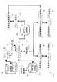
図2および図3はEMS10のネットワーク構成を示すブロック図である。図2の例では、EMS10、MDMS11およびRTU13は内部ネットワーク17(系統ネットワーク17)に接続されている。EMS10は、遠隔管理用ネットワーク21にも接続されており、この遠隔管理用ネットワーク21は、ゲートウェイ(GW)/ファイアウォール(FW)22を介してインターネット3に接続されている。インターネット3には天気予報サーバ6とメンテナンス用管理端末5が接続されており、EMS10は、遠隔管理用ネットワーク21、ファイアウォール22およびインターネット3を介して、天気予報サーバ6およびメンテナンス用管理端末5と通信を行う。 2 and 3 are block diagrams showing the network configuration of the
また、図3の例では、EMS10は、ルータ23を介して内部ネットワーク17に接続されている。内部ネットワーク17には、MDMS11とRTU13が接続されている。ルータ23には遠隔管理用ネットワーク21も接続されている。 In the example of FIG. 3, the
図2および図3は一例であり、他のネットワーク構成を採用してもよい。ただし、本実施形態のEMS10は、基本的なネットワーク機能として、インターネット3接続用のインタフェースと、内部ネットワーク17接続用のインタフェースとを有する。この機能を備えている限り、種々のネットワーク形態を採用することができる。 2 and 3 are examples, and other network configurations may be adopted. However, the
なお、遠隔管理用ネットワーク21と系統ネットワーク17の物理レイヤおよびリンクレイヤとして、イーサネット(登録商標)やIEEE802.11に準拠した無線LANなどの種々の形態が採用可能である。ネットワークレイヤとして、インターネット3プロトコル(IP)を使用する場合、IPv4とIPv6のいずれでもよい。 As the physical layer and link layer of the
図2では、EMS10が二つのネットワークに接続するために物理的に二つのネットワークインタフェース(以下、ネットワークI/F)を有する例を示しているが、図3に示すように、EMS10が物理的に一つのネットワークI/Fを有し、EMS10に二つ以上のIPアドレスを付与して論理的に複数のインタフェースを持つようにしてもよい。この場合、ルータ23は、EMS10のアドレスXから送信されるパケットを遠隔管理用ネットワーク21に転送し、アドレスYから送信されるパケットを系統ネットワーク17に転送するように設定しておく。 FIG. 2 shows an example in which the
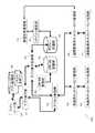
図4は本実施形態によるEMS10の概略構成を示すブロック図である。図4に示したEMS10はアプリ実行部31、アクセス制御部32、ポリシー記憶部33、ポリシー設定部34、アプリロード部35、アプリ記憶部36、I/F管理部37、系統ネットワークI/F管理部38、遠隔管理用ネットワークI/F管理部39、系統ネットワークI/F処理部40、遠隔管理用ネットワークI/F処理部41、および登録状態管理部42を有する。 FIG. 4 is a block diagram showing a schematic configuration of the
アプリ記憶部36は、EMS10が実行するアプリケーションを記憶する。ここで、アプリケーションとは、プログラムモジュールであり、例えば、MDMS11と通信を行って消費電力情報を取得したり、電力の需給予測の計算を行ってRTU13と通信して電力供給量を調整する処理を行うプログラムモジュールを指す。また、アプリケーションとは、インターネット3経由で接続されたメンテナンス用管理端末5と通信を行い、どのようなログ情報を記録すべきかの指示を受け付けたり、ログ情報などをメンテナンス用管理端末5に送信する処理を行うプログラムモジュールも指す。 The
プログラムモジュールの実装形態はハードウェアでもソフトウェアでも、その組み合わせでもよいが、ここではソフトウェアモジュールとして実装した場合の例について述べる。なお、図4ではエネルギー管理アプリがアプリ記憶部36に格納されている例を示しているが、これ以外のアプリケーションがアプリ記憶部36に格納されていてもよい。 The implementation form of the program module may be hardware, software, or a combination thereof. Here, an example of implementation as a software module will be described. FIG. 4 shows an example in which the energy management application is stored in the
アプリロード部35はアプリ記憶部36に格納されたアプリケーションを必要に応じてロードする処理を行う。アプリケーションのロードはユーザの指示で行ってもよいし、毎日決まった時刻などに定期的にロードしてもよいし、電力消費が一定の閾値を超えた場合など特定のイベントが発生した場合にロードしてもよいし、ネットワークからの所定の信号を受信する事によってロードしてもよい。 The
アプリ実行部31はアプリロード部35がロードしたアプリケーションを実行する。アプリケーションは複数同時に実行されることを想定しており、また系統ネットワーク17に接続された機器を制御したりデータを取得したりするアプリケーションと、メンテナンス用の処理を行うアプリケーションとは、別々のアプリケーション(例えば別々のファイルのソフトウェアモジュール)として構成されることを想定している。なお、複数のアプリケーションは必ずしも同時に実行されるとは限らず、場合によっては、一つのアプリケーションが実行される場合もありうる。 The
I/F管理部37は、アプリケーションが接続先機器を指定した場合にアプリケーションから送受信されるデータ(パケット)が、系統ネットワークI/F管理部38で処理するデータか、遠隔管理用ネットワークI/F管理部39で処理するデータかを選別する処理を行う。接続先機器は、例えばIPアドレスを用いて指定される。その場合、I/F管理部37はアプリケーションから送信されたパケットに含まれる宛先IPアドレスから、どちらのI/F管理部37で処理させるデータかを選別する。 The I /
系統ネットワークI/F管理部38は、系統ネットワーク17に接続された機器と通信を行うためのデータリンクレイヤ処理、ネットワークレイヤ処理、およびトランスポートレイヤ処理を行う。一方、遠隔管理用ネットワークI/F管理部39は、遠隔管理用ネットワーク21に接続された機器あるいはメンテナンス用管理端末5と通信を行うためのデータリンクレイヤ処理、ネットワークレイヤ処理、およびトランスポートレイヤ処理を行う。 The system network I /
なお、系統ネットワーク17と遠隔管理用ネットワーク21がともにネットワークプロトコルとしてTCP/IPを用いる場合、系統ネットワーク17に付与されるIPアドレスと遠隔管理用ネットワーク21に付与されるIPアドレスに違いはあるものの、両I/F管理部38,39の処理内容に違いはない。 When both the
両I/F管理部38,39の処理が終わると、系統ネットワークI/F処理部40または遠隔管理用ネットワークI/F処理部41の処理が行われる。系統ネットワークI/F処理部40は系統ネットワーク17と通信を行うための物理レイヤ処理の処理を行う。遠隔管理用ネットワークI/F処理部41は遠隔管理用ネットワーク21に接続された機器と通信を行うための物理レイヤ処理の処理を行う。 When the processing of both I /
系統ネットワークI/F管理部38と系統ネットワークI/F処理部40を専用ネットワークI/F部に対応し、遠隔管理用ネットワークI/F管理部39と遠隔管理用ネットワークI/F処理部41は公衆ネットワークI/F部に対応する。本実施形態では、2つのネットワークI/F処理部を有するが、3つ以上のネットワークI/F処理部を設けて、I/F管理部37で任意の一つを選択してもよい。 The network network I /
図2に示すように、EMS10は異なるネットワーク(内部ネットワーク17と遠隔管理用ネットワーク21)に接続されており、二つの物理インタフェースを有する。これらの物理インタフェースがそれぞれ系統ネットワークI/F処理部40と遠隔管理用ネットワークI/F処理部41に対応する。 As shown in FIG. 2, the
また、図2に示すネットワーク構成では、系統ネットワーク17と遠隔管理用ネットワーク21は異なるネットワークアドレス(例えばIPアドレス)が付与される。I/F管理部37は、アプリケーションで指定された宛先IPアドレスが系統ネットワーク17と遠隔管理用ネットワーク21のどちらのネットワークアドレスの範囲に含まれるか検索し、利用するネットワークI/Fを決定する処理を行うことになる。 In the network configuration shown in FIG. 2, different network addresses (for example, IP addresses) are assigned to the
ポリシー記憶部33は、アプリケーションごとに、どのネットワークI/Fに対するアクセスを許可するかを定めたアクセス可否情報(ポリシー)を蓄積する。つまり、ポリシー記憶部33は、個々のアプリケーションごとに、アプリケーションの識別情報と、複数のネットワークI/F部のそれぞれに対するアクセスを許可するか否かを示すアクセス可否情報とを、対応付けて記憶する。 The
ポリシー設定部34は、ポリシー記憶部33に対してポリシーを設定する。つまり、ポリシー設定部34は、個々のアプリケーションごとに、複数のネットワークI/F部のそれぞれに対するアクセスを許可するか否かを設定する。ポリシーのデータ構造や設定方法については後述する。 The
アクセス制御部32は、アプリケーションからのネットワークI/F利用要求に基づいて、ポリシー記憶部33からポリシーを取得し、比較処理を行ってアプリケーションがネットワークI/Fのアクセスを許可されているか否かを判断するアクセス制御処理を行う。アクセス制御の処理の詳細については後述する。 The
本実施形態によるEMS10は、アプリケーション登録フェーズとアクセス制御フェーズとの二つの処理を行う。アプリケーション登録フェーズでは、アプリケーションのネットワークI/F利用に先立ち、ネットワークを利用してよいアプリケーションをあらかじめ登録しておく処理を行う。一方、アクセス制御フェーズでは、実際にアプリケーションがネットワークI/Fを利用する時に、そのアプリケーションが利用してよいインタフェースか否か判別処理を行う。 The
まず、EMS10が行うアプリケーション登録フェーズの処理手順について説明する。アプリケーション登録フェーズでは、ポリシー設定部34を使ってポリシー記憶部33に対して、どのアプリケーションがどのネットワークI/Fのアクセスを許可するかを登録する処理を行う。 First, the processing procedure of the application registration phase performed by the
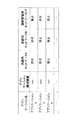
図5はポリシー記憶部33に登録される情報のデータ構成の一例を示す図である。図5に示すように、ポリシー記憶部33には、各アプリケーションごとに、アプリケーション識別情報、系統用ネットワークI/Fのアクセス可否情報、遠隔管理用ネットワークI/Fのアクセス可否情報が登録されている。アプリケーション識別情報はアプリケーションを識別するための情報である。アプリケーションを識別する情報として、以下の3つのいずれか、あるいはその任意の組み合わせが考えられる。
(a)アプリケーションプログラムファイルが保存されている場所(パス名+ファイル名)。
(b)アプリケーションが実行される時に付与されるプロセス名またはプロセス識別情報。
(c)アプリケーションプログラムのハッシュ値。FIG. 5 is a diagram illustrating an example of a data configuration of information registered in the
(A) Location (path name + file name) where the application program file is stored.
(B) Process name or process identification information given when the application is executed.
(C) A hash value of the application program.
このように、ポリシー記憶部33は、アプリケーションの種類によって、どちらのネットワークI/Fに対するアクセスを許可するかのアクセス可否情報を登録する。例えば、系統ネットワーク17を経由してMDMS11に対して電力需要抑制命令を送信するアプリケーションについては、系統用ネットワークI/Fに対するアクセスを許可するが、遠隔管理用ネットワークI/Fに対するアクセスを禁止する。 As described above, the
同様に、RTU13から発電情報を取得したり、RTU13に対して発電命令を送信したりするアプリケーションについても、系統用ネットワークI/Fに対するアクセスを許可するが、遠隔管理用ネットワークI/Fに対するアクセスは禁止する。 Similarly, access to the grid network I / F is permitted for applications that acquire power generation information from the
一方、インターネット3を経由してメンテナンス用管理端末5に対してログ情報を送信したりするアプリケーションについては、遠隔管理用ネットワークI/Fに対するアクセスを許可し、系統用ネットワークI/Fに対するアクセスは禁止する。同様にインターネット3上のサーバからインターネット3を経由して天気情報を取得するアプリケーションについてもインターネット3に接続する遠隔管理用ネットワークI/Fのアクセスを許可し、系統用ネットワークI/Fに対するアクセスは禁止する。また、ログ情報を記録するといったネットワークの機能を用いないアプリケーションに対しては両方のネットワークI/Fに対するアクセスを禁止する。 On the other hand, for applications that send log information to the
なお、後述するように、登録されていないアプリケーションについてはネットワークI/Fに対するアクセスを禁止するというルールにしておけば、ネットワークI/Fを利用するアプリケーションのポリシーをポリシー記憶部33に登録しておけばよく、ネットワークI/Fに対するアクセスを禁止するアプリケーションを明示的に登録しておくことは必須ではないため、アプリケーション登録の手間を省くことができる。 As will be described later, if the rule is that access to the network I / F is prohibited for applications that are not registered, the policy of the application that uses the network I / F can be registered in the
一般的なEMS10では、メンテナンス用管理端末5と通信するアプリケーションは系統用ネットワークI/Fを利用するが、本実施形態では明示的にポリシー記憶部33にポリシーを登録しておかない限り、アプリケーションが系統用ネットワークI/Fにアクセスすることを禁止する設定にすることに利点がある。 In a
特にアプリケーションが外部からのアクセスを許可するような、いわゆるサーバとして機能する場合に極めて有用である。昨今、インターネット3から管理者の権限を不正に取得して装置に侵入したり、不正にデータを取得したりするような不正アクセスによるサイバー犯罪が後を絶たない。EMS10では電力の需給予測などを行う他、RTU13などEMS10以外の装置に対して電力の需要命令を送信したりするため、EMS10内のデータが改ざんされたり、EMS10以外の装置に対して不正な電力の需要命令を送信したりすると正常に需給を管理することができず、需給のバランスが崩れて停電などの大規模災害を引き起こす危険性がある。 This is extremely useful particularly when the application functions as a so-called server that permits access from the outside. In recent years, cyber crimes due to unauthorized access such as illegally acquiring the authority of the administrator from the
特にアプリケーションがインターネット3からアクセス可能な状態でサーバ機能を提供する場合、アプリケーションの実装ミスや設定ミスによって不正に管理者権限が取得されてしまうと、攻撃者はインターネット3を経由して系統ネットワーク17に不正なデータを送信可能となり、RTU13やMDMS11などの装置に不正な命令を送信したり、EMS10をRTU13やMDMS11に対して侵入を仕掛ける際の踏み台として利用されたりする危険性がある。各アプリケーションがアクセス可能なネットワークI/Fを制限することで、仮にアプリケーションに脆弱性が含まれていて攻撃者がその脆弱性を利用してアプリケーションを乗っ取り、遠隔管理用ネットワーク21から侵入したとしても、そのアプリケーションを使って系統ネットワーク17に不正なパケットを送信することを防ぐことができる。 In particular, in the case where the server function is provided in a state where the application is accessible from the
登録状態管理部42はポリシー記憶部33にアプリケーションを登録してもよい状態か否かを判別する。前述のようにポリシー記憶部33にアプリケーションを登録できるのはポリシー設定部34に限定されるが、ポリシー設定部34がポリシー記憶部33にアプリケーションを登録する際、登録状態管理部42は、ポリシー設定部34がアプリケーションの登録を許可できる状態(登録許可状態)にあるか否かを確認する。登録禁止状態の場合はポリシー設定部34によるアプリケーションの登録を禁止し、登録許可状態の時にポリシー設定部34によるアプリケーションの登録を許可する。これは不正にアプリケーションが登録されることを防ぐためである。 The registration
上述のように、遠隔管理用ネットワーク21を経由して不正者がEMS10に侵入し、本来許可されていないアプリケーションに対してネットワークI/Fのアクセスが許可されるようポリシー設定部34に登録する危険性がある。これを防ぐためにポリシーへの登録が正規のオペレーターによる操作であることを確認する処理が必要となる。 As described above, a risk that an unauthorized person enters the
なお、登録状態管理部42が確認する登録許可状態とは、以下の3つのいずれか、あるいはその任意の組み合わせである。
(a)アプリケーションが遠隔管理用ネットワークI/F管理部39を使ってパケットの送受信を行っていない時(遠隔管理用ネットワーク21を経由したネットワークコネクションが確立されていない時)。
(b)ポリシー設定部34が遠隔管理用ネットワークI/F管理部39からの入力ではなく、キーボードからの入力に基づいてポリシー記憶部33への登録を行っていることが確認できたとき。
(c)系統ネットワークI/F管理部38を使ってパケットの送受信を行っていないとき。The registration permission state confirmed by theregistration
(A) When the application is not transmitting / receiving packets using the remote management network I / F management unit 39 (when the network connection via the
(B) When it is confirmed that the
(C) When packet transmission / reception is not performed using the system network I /
図6はポリシー設定部34がアプリケーションをポリシー記憶部33に登録する処理手順の一例を示すフローチャートである。まず、登録対象のアプリケーションを選択し、ポリシー設定部34に登録対象のアプリケーションを指定する(ステップS1)。次に、ポリシー設定部34またはポリシー記憶部33は登録対象のアプリケーション識別情報を収集する(ステップS2)。これらの手順はEMS10をネットワークに接続する前に行ってもよいし、ネットワーク接続後のアプリケーションのインストール時に行ってもよい。 FIG. 6 is a flowchart illustrating an example of a processing procedure in which the
アプリケーション識別情報の収集は、オペレーターに手入力させてもよい。以降では、ポリシー設定部34が自動的に情報を収集する処理の例について説明する。その前提として、アプリケーション開発者がアプリケーション識別情報をアプリケーションパッケージのファイルに含めておく。 Collection of application identification information may be manually input by an operator. Hereinafter, an example of processing in which the
図7はアプリケーションパッケージのファイル構成を示す図である。なお、図7ではアプリケーション識別情報としてアプリケーション実行プログラムのハッシュ値を使うものとする。アプリケーション識別情報はアプリケーションを識別可能な値であれば、アプリケーション開発者が一意に付けたID、一意に付けたファイル名(パッケージ名)などでもよい。図7に示すように、アプリケーションパッケージには複数のファイルが含まれている。これらファイルは、アプリケーションの実態であるアプリケーション実行ファイル、設定データやインストーラーなどが含まれたアプリケーションデータ、それにアプリケーション識別情報(ハッシュ値)などを含んでいる。 FIG. 7 shows the file structure of the application package. In FIG. 7, the hash value of the application execution program is used as the application identification information. The application identification information may be an ID uniquely assigned by the application developer, a uniquely assigned file name (package name), or the like as long as it is a value that can identify the application. As shown in FIG. 7, the application package includes a plurality of files. These files include an application execution file which is the actual state of the application, application data including setting data and an installer, and application identification information (hash value).
なお、オプションとしてどのネットワークI/Fを利用するアプリケーションかを示す情報を記述したファイルを含めてもよい。 As an option, a file describing information indicating which network I / F is used may be included.
アプリケーション開発者はアプリケーションインストールに先立ちアプリケーション生成時にアプリケーション識別情報(ハッシュ値)を事前に計算しておき、パッケージファイルと共に配布する。 Prior to application installation, the application developer calculates application identification information (hash value) in advance when generating the application and distributes it together with the package file.
ポリシー設定部34はEMS10にインストールされているアプリケーション実行プログラムのハッシュ値を計算するか、またはアプリケーションパッケージに含まれていたファイルに含まれるハッシュ値をアプリケーション識別情報とする。 The
ポリシー設定部34は、アプリケーションの登録に必要な情報の収集が終了すると、登録状態管理部42の状態を検査する(ステップS3)。その結果、登録状態管理部42が登録許可状態か否かを判定し(ステップS4)、登録許可状態でなければ(ステップS5)、エラー処理を行って(ステップS6)、以降の処理は行わない。登録可能状態であれば、ポリシー設定部34は収集した情報をポリシー記憶部33に登録する(ステップS7)。この時、EMS10にインストールされているアプリケーション実行プログラムのハッシュ値を計算し、その計算値がアプリケーションパッケージに含まれていたファイルに含まれるハッシュ値と一致するか否かを検査し、一致する場合にアプリケーションをハッシュ値と共に登録する。この時さらに、アプリケーションパッケージのハッシュ値にアプリケーション開発者の秘密鍵で署名を施してアプリケーションパッケージファイルに含め、かつポリシー記憶部33は事前に秘密鍵に対応する公開鍵をインストールしておけば、ポリシー設定部34はアプリケーション登録時にその公開鍵で署名を検証し、署名検証処理が成功した時に登録する。このように、署名検証処理を行うことで、信頼できるアプリケーション開発者が開発したアプリケーションであること、さらにアプリケーションパッケージが改変されていないことが保証できる。 When the collection of information necessary for application registration is completed, the
なお、アプリケーションパッケージのハッシュ値に署名を施してもよいし、アプリケーションパッケージ内の特定のファイル、例えばアプリケーション実行ファイルやアプリケーション識別情報に署名を施してもよい。その後、ポリシー設定部34はアプリケーション識別情報と、系統用ネットワークI/Fまたは遠隔管理用ネットワークI/Fのいずれかのインタフェースに対するアクセスを許可するかを示すアクセス可否情報をポリシー記憶部33に登録する(ステップS7)。これにより、アプリケーションの登録処理が終了する(ステップS8)。 The hash value of the application package may be signed, or a specific file in the application package, for example, an application execution file or application identification information may be signed. Thereafter, the
どのインタフェースに対するアクセスを許可するかを示すアクセス可否情報として、どのネットワークI/Fにアクセスするアプリケーションかを示す情報がアプリケーションパッケージ内に含まれている場合は、その情報を利用してもよいし、含まれていない場合には管理者がアプリケーションの内容に応じてアクセス可能なインタフェースを選択してもよい。もしアプリケーションパッケージにアプリケーション実行ファイルがどのIPアドレスの機器と接続するかそのIPアドレス利用情報が含まれていれば、その情報を利用して登録してもよい。 When information indicating which network I / F is an application to be accessed is included in the application package as access permission information indicating which interface is permitted to access, that information may be used. If not included, the administrator may select an accessible interface according to the contents of the application. If the application package contains information on which IP address the application execution file is connected to, the IP address usage information may be registered using that information.
なお、IPアドレス利用情報はIPアドレス(123.456.789.123)の形式でもよいし、DNSドメイン名(bar.foo.com)でもよい。 The IP address usage information may be in the form of an IP address (123.456.789.123) or a DNS domain name (bar.foo.com).
次に、EMS10が行うアクセス制御フェーズの処理手順について説明する。図8はアクセス制御フェーズにおけるアプリ実行部31とアクセス制御部32の処理手順の一例を示すフローチャートである。まず、アプリ実行部31はアプリケーションが利用するIPアドレス(またはDNSドメイン)とアプリケーション識別情報をアクセス制御部32に通知する(ステップS11)。この処理はアプリケーション実行プログラム自身がアクセス制御部32に通知してもよいし、アプリケーション実行に先立ち、アプリ実行部31がアプリケーションパッケージ内に含まれるIPアドレス利用情報とアプリケーション識別情報を取得してアクセス制御部32に通知してもよい。アクセス制御部32は受信したIPアドレスから系統用ネットワークと遠隔管理用ネットワーク21のどちらのネットワークにアクセスするかをI/F管理部37に問い合わせる(ステップS12)。 Next, an access control phase processing procedure performed by the
なお、IPアドレスの代わりにDNSドメイン名を利用している場合は、I/F管理部37に通知する前にDNSサーバからIPアドレスに変換する処理を行ってもよい。 If a DNS domain name is used instead of an IP address, a process of converting from a DNS server to an IP address may be performed before notifying the I /
図9はI/F管理部37が管理するテーブルの一例を示す図である。この管理テーブルは、どのIPアドレスがどちらのネットワークI/Fに対応するかを管理する。図9に示すように、IPアドレスとネットワークI/Fは1対1に対応してもよいし、アドレス範囲ごとにネットワークI/Fに対応していてもよい。I/P管理部は、アクセス制御部32から指定されたIPアドレスがどのネットワークI/Fに対応するかをテーブルから検索し、ネットワークI/F名をアクセス制御部32に回答する(ステップS13)。 FIG. 9 is a diagram illustrating an example of a table managed by the I /
アクセス制御部32は、許可されたネットワークI/Fに対するアクセスであるか否かをポリシー記憶部33に問い合わせる(ステップS14)。ポリシー記憶部33は図5に示したテーブルに従って許可か禁止かをアクセス制御部32に回答する。アクセス制御部32は、ポリシー記憶部33からの回答に基づいて、アプリケーションがアクセスを要求したネットワークI/Fのアクセスが許可されているか否かを判定する(ステップS15,S16)。 The
禁止されたアクセスであればアプリ実行部31またはアプリケーションに対してそのことを通知し(ステップS17)、アプリケーションはエラー処理を行う(ステップS18)。もちろん、禁止されていてもアプリケーション実行中にネットワークI/Fを利用してネットワーク上の機器とコネクションを確立しようとする場合にはそのコネクション確立を禁止する。ネットワークI/Fに対するアクセスが許可されていれば、そのことをアプリケーションに通知して(ステップS19)、アプリケーションはネットワーク上の機器とネットワークコネクションの確立が成功する(ステップS20)。 If the access is prohibited, the
なお、このネットワークI/Fに対するアクセスの可否はファイアウォール装置などでよく用いられている機器のネットワークフィルタリングの仕組みを用いてもよいし、ネットワークコネクション確立命令をオペレーティングシステムに通知する際に、その命令をアクセス制御部32がブロックするように実装してもよい。 The network I / F can be accessed using the network filtering mechanism of equipment often used in firewall devices, etc., and when the network connection establishment command is notified to the operating system, the command is used. You may mount so that the
図8ではアプリケーションがどちらのネットワークI/Fにアクセスするかをアクセス制御部32がI/F管理部37に問い合わせていたが、アプリ実行部31がI/F管理部37に対してネットワークI/Fを問い合わせてもよい。 In FIG. 8, the
図10はアプリ実行部31がI/F管理部37に対してネットワークI/Fを問い合わせる場合の処理手順の一例を示すフローチャートである。まずアプリ実行部31はアプリケーションが利用するIPアドレスをI/F管理部37に問い合わせる(ステップS31)。I/F管理部37は図9のテーブルに従ってネットワークI/Fを特定して、アプリ実行部31に回答する(ステップS32)。アプリ実行部31はアプリケーションがアクセスするネットワークI/Fとアプリケーション識別情報をアクセス制御部32に通知する(ステップS33)。その後のアクセス制御部32の処理(ステップS34〜S39)は図8のステップS15〜S20と同じである。 FIG. 10 is a flowchart illustrating an example of a processing procedure when the
なお、この場合、アプリケーション開発者が必ずネットワークコネクション利用に先立ち、I/F管理部37にどちらのネットワークI/Fを利用するか問い合わせる処理を含めるよう、合意しておく必要がある。 In this case, it is necessary for the application developer to agree to include a process for inquiring which network I / F to use in the I /
次に、IPアドレスとネットワークI/Fの対応を管理する別例について示す。次世代電力網の特徴の一つにネットワーク構成が機器によって管理されていることが挙げられる。一般的なインターネット3では個々のネットワーク管理者が個々の機器に個々のドメイン名やIPアドレスを割り振るローカルネットワークをそれぞれ運用・管理しており、すべてのローカルネットワーク上の機器を統一的に管理する管理者は存在しない。しかし次世代電力網では、図1に示す分散電源14や蓄電装置15などがどの内部ネットワーク17(電力系統ネットワーク17)に接続されており、個々の電力系統ネットワーク17を束ねるネットワーク構成がどのような形態であるかを示すネットワークトポロジーの情報が管理されている。より具体的には、IEC 61850規格(CIM(Common Information Model))に代表されるようにネットワークトポロジーのモデルの記述方法が規定されている。すなわち、次世代電力網(系統ネットワーク17)に蓄電装置15などの機器が新たに接続されたり、停電やメンテナンス作業などによって切断されたりした場合に、データベースの内容を更新する仕組みが次世代電力網では提供されている。このデータベース管理はEMS10が行ってもよいし、CIMデータベースの専用装置が行ってもよい。以下では、EMS10がCIMデータベースを管理する構成について説明する。 Next, another example for managing the correspondence between the IP address and the network I / F is shown. One of the features of the next-generation power network is that the network configuration is managed by equipment. In the
図11は第1の実施形態の第1の変形例に係る電力管理システム1aの概略構成を示すブロック図である。図1では、EMS10とすべてのRTU13が共通の内部ネットワーク17に接続される例を説明したが、図11では、電力系統管理装置2内に複数の系統ネットワークが設けられ、それぞれの系統ネットワークがルータを介して接続される。 FIG. 11 is a block diagram showing a schematic configuration of a
より具体的には、図1では電力系統管理装置2内のEMS10やRTU13などが接続されるネットワークを内部ネットワーク17(系統ネットワーク17)と総称したが、図11に示す電力系統管理装置2では、分散電源14と蓄電装置15およびそれらに接続されるRTU13は系統ネットワーク17内のネットワークAに接続され、送配電制御装置16とそれに接続されるRTU13は系統ネットワーク17内のネットワークBに接続されている。そしてネットワークAとネットワークBはルータAを介してEMS10と接続されている。 More specifically, in FIG. 1, the network to which the
以下に示す例では、EMS10がCIMデータベース(CIM DB)を利用することで、アプリケーションが系統ネットワーク17か遠隔管理用ネットワーク21のどちらのネットワークに所属する機器と接続しようとしているかを特定し、かつ系統ネットワーク17の中のどのネットワークあるいは機器に接続しようとしているかを特定して、アクセス制御を行うものである。すなわち、図11の電力管理システム1aは、アプリケーションが天気予報サーバ6やRTU13に接続してよいかだけでなく、分散電源14に接続されたRTU13に接続してよいか(ネットワークAの機器に接続してよいか)、あるいは送配電制御装置16のRTU13に接続してよいか(ネットワークBの機器に接続してよいか)といったことまで管理することができる。 In the example shown below, the
図12は図11のEMS10aの内部構成の一例を示すブロック図である。図12のEMS10aはCIM DB記憶部43とCIM DB管理部44を備えている点が図4と異なる。CIM DB記憶部43は上述したCIMデータベースのデータを格納する。CIM DB管理部44は、ネットワークに機器が接続された時や、ネットワークから機器が切断された時など、ネットワークの構成が変更された時に、そのことを示すメッセージを外部の機器から受信し、CIM DB記憶部43に通知して、ネットワークの構成とCIM DB記憶部43の内容が一致するようにCIM DB記憶部43のデータを書き換える処理を行う機能を有する。 FIG. 12 is a block diagram showing an example of the internal configuration of the
図13はポリシー記憶部33が管理する情報の構成の一例を示す図である。図13のポリシー記憶部33は、遠隔管理用ネットワークI/Fに加えて、系統ネットワーク17のうちネットワークAとネットワークBの利用許可情報についても管理できる点が図5とは異なる。 FIG. 13 is a diagram illustrating an example of a configuration of information managed by the
図14は図13のEMS10aが行うアクセス制御の処理手順を示すフローチャートである。図13のEMS10aが行うポリシー記憶部33への登録処理手順は図6と比べて、個々のアプリケーションがネットワークAとネットワークBへのアクセス許可情報を加えるだけの違いしかないため、説明を省略する。 FIG. 14 is a flowchart showing a processing procedure of access control performed by the
図14において、アプリ実行部31がI/F管理部37を使ってインタフェースを特定するまでのステップS41〜S43は図8のステップS11〜S13と同様の処理手順でよい。その後、遠隔管理用I/Fか否かを判定し(ステップS44)、遠隔管理用ネットワークI/Fではなく系統用ネットワークI/Fだった場合、アクセス制御部32はCIM DB記憶部43からネットワーク構成を取得する(ステップS45)。そしてアクセス制御部32はアプリケーションが該当するネットワーク(ネットワークA、ネットワークB、遠隔管理用ネットワーク21)へのアクセスが許可されているか否かをポリシー記憶部33に問い合わせ、許可されたアクセスであるか否かを判定する。それ以降の処理(ステップS46〜S52)は図8のステップS14〜S20と同じ処理手順でよい。 In FIG. 14, steps S41 to S43 until the
このように、第1の実施形態では、 個々のアプリケーションごとに、個々のネットワークI/F部のアクセス可否情報をポリシー設定部34で判断してポリシー記憶部33に記憶しておくため、アプリ実行部31が実行するアプリケーションに対して特定のネットワークI/F部のアクセスを許可するか否かを簡易かつ迅速に決定できる。これにより、不正なアプリケーションによるネットワークI/F部へのアクセスを禁止でき、本来の電力制御の処理に影響を与えずにネットワークからの不正アクセスを防止できる。 As described above, in the first embodiment, for each individual application, the access setting information of each network I / F unit is determined by the
また、系統ネットワーク17の詳細なネットワーク構成を記憶するCIM DB記憶部43を設ければ、系統ネットワーク17内の個々のネットワークごとに、アプリケーションによるアクセスを許可するか否かを設定でき、系統ネットワーク17内の個々のネットワーク単位でアクセス制限をかけることができ、不正アクセス防止をより徹底させることができる。 Further, if the CIM
(第2の実施形態)
第1の実施形態では、ネットワークI/Fを利用するアプリケーションを事前に登録しておき、アプリケーションはネットワークI/F利用時にネットワークI/Fを利用してよいかどうかアプリケーション自身がEMS10aに可否を問い合わせる。ネットワークI/Fの利用が許可されていることを示すポリシーが登録されているアプリケーションであれば特定のネットワークI/Fに対するアクセスを許可し、そうでなければアクセスを禁止することで、特定のアプリケーションしか特定のネットワークI/Fの利用をできないように禁止することを実現していた。すなわち、第1の実施形態は、アクセス制御の判定をアプリケーションがネットワーク上の機器とネットワークコネクションを確立する前に行っている。これに対して、第2の実施形態は、アプリケーションがネットワーク上の機器とネットワークコネクションを確立する時に自動的にネットワークI/Fのアクセス可否を判定する処理を行う。(Second Embodiment)
In the first embodiment, an application that uses the network I / F is registered in advance, and the application itself inquires of the
図15は第2の実施形態によるEMS10bの概略構成を示すブロック図である。図15のEMS10bはアプリ実行管理部45を備えている点が図4のブロック図とは異なる。前述したように、EMS10bでは複数のアプリケーションが同時に実行される場合がある。第2の実施形態ではアプリケーションの実行が開始されると、その実行中のアプリケーションがアプリ実行管理部45に登録される。アプリケーションの実行が終了するとアプリ実行管理部45からアプリケーションが削除される。すなわちアプリ実行管理部45は現在どのようなアプリケーションが実行されているかを管理する処理を行う。 FIG. 15 is a block diagram showing a schematic configuration of the
図16はアプリ実行管理部45が管理するデータ構造を示す図である。ここで、図13に示すようなデータがポリシー記憶部33に登録されているものとする。アプリ実行管理部45はアプリケーションの実行を監視し、アプリ実行部31がアプリケーションの実行を開始するとポリシー記憶部33に登録されたアプリケーションか否かを調べる。 FIG. 16 is a diagram showing a data structure managed by the application
例えば、アプリケーションAが実行された場合、アプリ実行管理部45はアプリケーションAが実行されたことを検出して、ポリシー記憶部33にアプリケーションAが登録されているか否かを確認する。例えば、アプリケーションAのポリシーがポリシー記憶部33に登録されている場合には、図16に示すように、アプリケーション名とアプリケーション識別情報、ネットワークI/F情報をアプリ実行管理部45にロードする。 For example, when the application A is executed, the application
同様に、アプリケーションAが実行されている状態で、アプリケーションCとアプリケーションEが実行されると、アプリ実行管理部45にロードされるデータは図16に示すようなものになる。ポリシー記憶部33に登録されていないアプリケーションであればネットワークI/Fの利用は禁止状態として登録する。すなわち、図16に示すようにアプリ実行管理部45には現在実行中のアプリケーションに関するポリシーがロードされることになる。図16の例では、アプリケーションA、C、Eが現在実行されており、AとCはポリシー設定部34に登録されたアクセス可否情報がそのままアプリ実行管理部45に登録される。アプリケーションBやDは現在実行されていないため、アプリ実行管理部45にはロードされていない。一方、アプリケーションEはポリシー設定部34にはアクセス可否情報が登録されていないが実行中のアプリケーションであるため、ネットワークI/Fの利用はすべて禁止状態となる。 Similarly, when application C and application E are executed while application A is being executed, the data loaded into application
なお、アプリケーション識別情報は、第1の実施形態と同様に、(a)アプリケーションプログラムファイルが保存されている場所(パス名+ファイル名)、(b)アプリケーションが実行される時に付与されるプロセス名またはプロセス識別情報、(c)アプリケーションプログラムのハッシュ値のいずれでもよく、これらの任意の組み合わせでもよい。以下では(c)の情報を用いた例について説明する。 As in the first embodiment, the application identification information includes (a) a location (path name + file name) where the application program file is stored, and (b) a process name given when the application is executed. Alternatively, it may be either process identification information or (c) a hash value of an application program, or any combination thereof. Below, the example using the information of (c) is demonstrated.
仮にアプリケーションCの実行が終了した場合には、アプリ実行管理部45はアプリケーションCに対応するエントリー(ポリシー)をアプリ実行管理部45から削除する。 If the execution of the application C is finished, the application
ただし、ポリシー記憶部33に格納されたアプリケーションCに対応するエントリーは削除しない。これはポリシー記憶部33に格納されたデータは現在実行中のアプリケーションとは関係なくポリシーを管理するデータベースであり、かつポリシー記憶部33のデータを追加・削除できるのはポリシー設定部34に限定しているためである。 However, the entry corresponding to the application C stored in the
また、アプリケーションの実行に先立ち、アプリケーションをポリシー記憶部33に登録する必要があるが、この処理手順は第1の実施形態と同じであるため説明を省略する。 Prior to executing the application, it is necessary to register the application in the
次に、第2の実施形態によるEMS10bが行うアクセス制御フェーズの処理手順について説明する。図17は第2の実施形態によるEMS10bが行うアクセス制御フェーズのアプリ実行部31とアクセス制御部32の処理手順を示す図である。まず、アプリケーションの実行時にアプリ実行管理部45にアプリケーションを登録する。次にアプリ実行部31はネットワーク上の機器と接続するためにネットワークコネクション確立要求をアクセス制御部32に送信する(ステップS61)。このネットワークコネクション確立要求には少なくとも確立先の機器のIPアドレスまたはDNSドメイン名が含まれる。アクセス制御部32はコネクション確立要求の通知を受けると、そのコネクション確立要求がどのアプリケーションから発行されたものであるかを調査して、アプリケーションを特定する(ステップS62)。この調査にはアプリ実行管理部45が管理している情報(図16の情報)を用いる。別の方法として、現在動作中のアプリケーションプロセスリストの中から特定してもよいし、もしネットワークコネクション確立要求に実行中のアプリケーション名またはアプリケーション識別情報が含まれている場合には、その情報を用いてアプリケーションを特定してもよい。 Next, an access control phase processing procedure performed by the
次に、アクセス制御部32はコネクション確立要求に含まれるIPアドレスがどのインタフェースに対応するかI/F管理部37に問い合わせて(ステップS63)、系統用ネットワークI/Fか遠隔管理用ネットワークI/Fかを特定する(ステップS64)。 Next, the
次に、遠隔管理用I/Fか否かを判定して(ステップS65)、系統用ネットワークI/Fであれば、CIM DB記憶部43からネットワーク構成を取得する(ステップS66)。ステップS66の処理が終了した場合、またはステップS65で遠隔管理用I/Fと判定された場合、アクセス制御部32は、ネットワーク情報とアプリケーション識別情報をポリシー記憶部33に問い合わせる(ステップS67)。 Next, it is determined whether or not it is a remote management I / F (step S65). If it is a system network I / F, the network configuration is acquired from the CIM DB storage unit 43 (step S66). When the process of step S66 is completed, or when it is determined as the remote management I / F in step S65, the
次に、アクセス制御部32は、アプリケーション識別情報に基づいて、ネットワークI/Fのアクセスが許可されているかをアプリ実行管理部45に問い合わせる(ステップS68、S69)。もしアクセスが許可されていればコネクション確立要求を受け付けて所定の処理を行い(ステップS70)、もし禁止されていればコネクション確立要求に対してエラーを返す(ステップS71)。 Next, the
なお、この例では、図16に示すように、現在実行中のアプリケーションが個々のネットワークおよびネットワークI/Fを利用できるか否かのアクセス可否情報をアプリ実行管理部45が管理する例を示した。この例とは別に、アプリ実行管理部45が現在実行中のアプリケーションに対応するアプリケーション識別情報を管理し、個々のネットワークおよびネットワークI/Fを利用できるか否かのアクセス可否情報は管理しないようにしてもよい。その場合、アクセス制御部32がアプリケーション識別情報に基づいてネットワークアクセスが許可されているアプリケーションであるか否かをアプリ実行管理部45に問い合わせた場合、アプリ実行管理部45は、アプリケーションに該当するエントリーがポリシー記憶部33に格納されているかどうか検査し、格納されていない場合にはアクセスを拒否し、格納されている場合はそのアプリケーションに対応するエントリーをポリシー記憶部33からロードし、アプリケーションが利用するネットワークI/Fへのアクセスが許可されているか否かを判定してもよい。 In this example, as shown in FIG. 16, an example is shown in which the application
第1の実施形態では、アプリケーションに対してネットワークI/F部の利用が許可されているか否かをアクセス制御部32が通知する処理を行ったが、第2の実施形態ではコネクション確立要求処理が正常に行われるか、あるいはエラー処理を返すかで、アプリケーションによるネットワークI/Fの利用可否を判定するため、アプリケーション開発者は通常の手順に沿ってアプリケーションを開発すればよく、アプリケーション開発コストを下げることができる利点がある。 In the first embodiment, the
以下では、EMS10bの処理をより簡略化した構成を説明する。図18は第2の実施形態の一変形例によるEMS10cの概略構成を示すブロック図である。図18に示したEMS10cはI/F管理部37がなく、その代わりにアプリ実行管理部45がポリシー記憶部33を呼び出す点が図12のブロック図と異なる。図18のEMS10cはCIM DB記憶部43とCIM DB管理部44を備えているが、これらは必須の構成ではなく、省略してもよい。 Below, the structure which simplified the process of EMS10b is demonstrated. FIG. 18 is a block diagram showing a schematic configuration of the
図19は図18のEMS10cが行うアクセス制御フェーズの処理手順を示すフローチャートである。より具体的には、図19(a)はアプリケーション実行時におけるアプリ実行部31とアプリ実行管理部45の処理手順を示し。図19(b)はアプリケーション終了時におけるアプリ実行部31とアプリ実行管理部45の処理手順を示す。 FIG. 19 is a flowchart showing the processing procedure of the access control phase performed by the
図19(a)において、まずアプリケーションが実行されると、アプリ実行管理部45は系統用ネットワークI/Fにアクセスしてよいアプリケーションかをポリシー記憶部33に問い合わせる(ステップS81)。この時、ポリシー記憶部33に加えてCIM DB記憶部43を使って系統用ネットワークのネットワークAまたはBにアクセスしてよいアプリケーションか否かを問い合わせてもよい(ステップS82)。もし系統用ネットワークI/Fにアクセスしてもよいアプリケーションの場合にはアプリ実行管理部45は許可モードに入る(ステップS83)。 In FIG. 19A, when an application is first executed, the application
一方、系統用ネットワークI/Fに対するアクセスを禁止されているアプリケーションの場合にはアプリケーションをアプリ実行管理部45に登録し(ステップS84)、禁止モードに入る(ステップS85)。すなわち、アプリ実行管理部45には現在実行中で系統用ネットワークI/Fの利用が禁止されているアプリケーションのリストが登録されることになる。なお、禁止モードで系統用ネットワークI/Fにアクセスしてもよいアプリケーションが実行された場合でも、許可モードに入る事はなく、禁止モードのままである(不図示)。 On the other hand, in the case of an application for which access to the system network I / F is prohibited, the application is registered in the application execution management unit 45 (step S84), and the prohibit mode is entered (step S85). That is, the application
図20はアプリ実行管理部45に登録されるアプリケーションのリストの一例を示す図である。図20に示すように、実際には系統用ネットワークI/Fに対するアクセスが許可されているアプリケーションA,Cが実行されているが、アプリ実行管理部45には登録されず、その代わり系統用ネットワークI/Fに対するアクセスが禁止されているアプリケーションEが登録されている。 FIG. 20 is a diagram illustrating an example of a list of applications registered in the application
アプリケーションが終了した場合は、図19(b)に示すように、そのアプリケーションが系統用ネットワークI/Fをアクセスしてよいかをポリシー記憶部33に問い合わせる(ステップS91、S92)。もしアクセスが許可されているアプリケーションであれば、その状態を保持したまま処理を終える。 When the application is terminated, as shown in FIG. 19B, the
一方、禁止されているアプリケーションであれば他にアプリ実行管理部45に登録されているアプリケーションがあるか否かを調べ(ステップS93)、もしあればアプリ実行管理部45のモードを禁止モードのままにし(ステップS94)、もしアプリケーションがなければ許可モードに設定し(ステップS95)、終了したアプリケーションについての情報をアプリ実行管理部45から削除して終了する(ステップS96)。 On the other hand, if it is a prohibited application, it is checked whether there is another application registered in the application execution management unit 45 (step S93). If there is, the mode of the application
ここで、禁止モードに設定された場合は、ポリシー記憶部33とアプリ実行管理部45に登録されていない実行中のアプリケーションすべてについて、系統用ネットワークI/Fに対するアクセスが禁止される。逆に、許可モードに設定された場合は、ポリシー記憶部33とアプリ実行管理部45に登録されていない実行中のアプリケーションすべてについて、系統用ネットワークI/Fに対するアクセスが許可される。 Here, when the prohibit mode is set, access to the system network I / F is prohibited for all the applications that are not registered in the
なお、アプリ実行管理部45のアプリケーションの登録と削除は同時に実行されないよう排他的に管理することが望ましい。 It is desirable to exclusively manage the application
図21はアプリ実行部31がネットワーク上の機器に対してコネクション確立要求がアクセス制御部32に通知された時の処理手順を示すフローチャートである。アクセス制御部32はコネクション確立要求の通知を受けると(ステップS101)、アプリ実行管理部45にモードを問い合わせる(ステップS102、S103)。もし禁止モードであればコネクション確立要求に対してエラーを返す(ステップS104)。許可モードであれば所定のコネクション確立処理を行う(ステップS105)。 FIG. 21 is a flowchart showing a processing procedure when the
ここで、アプリ実行管理部45が禁止モードの場合とは、系統用ネットワークI/Fに対するアクセスが禁止されているアプリケーションが一つ以上実行されている状態にあるため、すべてのアプリケーションに対して系統用ネットワークI/Fに対するアクセスを禁止してしまう。これにより、アクセス制御部32がコネクション確立要求の発行元を調べる処理を省略することができるため、機器の構成を簡略化することができるだけでなく、実行速度を保ちつつアクセス制御を両立させることができる。 Here, the case where the application
以上説明したように、第2の実施形態によれば、ネットワーク上の機器と接続する処理を行うアプリケーションを開発する開発者が特別な処理を記述しなくても、図19の処理によって許可モードまたは禁止モードの設定を行うため、簡易な処理で個々のアプリケーションのネットワークアクセス制御を実現することができる。 As described above, according to the second embodiment, even if a developer who develops an application for performing a process for connecting to a device on the network does not write a special process, the process shown in FIG. Since the prohibit mode is set, network access control of individual applications can be realized with a simple process.
上述した実施形態で説明したエネルギー管理装置および電力管理システムの少なくとも一部は、ハードウェアで構成してもよいし、ソフトウェアで構成してもよい。ソフトウェアで構成する場合には、エネルギー管理装置および電力管理システムの少なくとも一部の機能を実現するプログラムをフレキシブルディスクやCD−ROM等の記録媒体に収納し、コンピュータに読み込ませて実行させてもよい。記録媒体は、磁気ディスクや光ディスク等の着脱可能なものに限定されず、ハードディスク装置やメモリなどの固定型の記録媒体でもよい。 At least a part of the energy management apparatus and the power management system described in the above-described embodiments may be configured by hardware or software. When configured by software, a program for realizing at least a part of the functions of the energy management apparatus and the power management system may be stored in a recording medium such as a flexible disk or a CD-ROM, and read and executed by a computer. . The recording medium is not limited to a removable medium such as a magnetic disk or an optical disk, but may be a fixed recording medium such as a hard disk device or a memory.
また、エネルギー管理装置および電力管理システムの少なくとも一部の機能を実現するプログラムを、インターネット3等の通信回線(無線通信も含む)を介して頒布してもよい。さらに、同プログラムを暗号化したり、変調をかけたり、圧縮した状態で、インターネット3等の有線回線や無線回線を介して、あるいは記録媒体に収納して頒布してもよい。 Further, a program that realizes at least a part of the functions of the energy management apparatus and the power management system may be distributed via a communication line (including wireless communication) such as the
本発明の態様は、上述した個々の実施形態に限定されるものではなく、当業者が想到しうる種々の変形も含むものであり、本発明の効果も上述した内容に限定されない。すなわち、特許請求の範囲に規定された内容およびその均等物から導き出される本発明の概念的な思想と趣旨を逸脱しない範囲で種々の追加、変更および部分的削除が可能である。 The aspect of the present invention is not limited to the individual embodiments described above, and includes various modifications that can be conceived by those skilled in the art, and the effects of the present invention are not limited to the contents described above. That is, various additions, modifications, and partial deletions can be made without departing from the concept and spirit of the present invention derived from the contents defined in the claims and equivalents thereof.
1 電力管理システム
2 電力系統管理装置
3 インターネット
4 宅内電力管理装置
5 メンテナンス用管理端末
6 天気予報サーバ
10 EMS(エネルギー管理装置)
11 MDMS
12 コンテントレータ
13 RTU
14 分散電源
15 蓄電装置
16 送配電制御装置
17 内部ネットワーク
18 スマートメータ
19 HEMS
21 遠隔管理用ネットワーク
22 ファイアウォール
23 ルータ
31 アプリ実行部
32 アクセス制御部
33 ポリシー記憶部
34 ポリシー設定部
35 アプリロード部
36 アプリ記憶部
37 I/F管理部
38 系統ネットワークI/F管理部
39 遠隔管理用ネットワークI/F管理部
40 系統ネットワークI/F処理部
41 遠隔管理用ネットワークI/F処理部
42 登録状態管理部DESCRIPTION OF
11 MDMS
12
14 Distributed
DESCRIPTION OF
Claims (5)
Translated fromJapanese前記アプリケーション記憶部に記憶されたアプリケーションを実行するアプリケーション実行部と、
複数のネットワークのそれぞれに対応した複数のネットワークインタフェース部と、
個々のアプリケーションごとに、前記複数のネットワークインタフェース部のそれぞれに対するアクセスを許可するか否かを設定するポリシー設定部と、
前記アプリケーションの識別情報と、前記複数のネットワークインタフェース部のそれぞれに対するアクセスを許可するか否かを示すアクセス可否情報とを記憶するポリシー記憶部と、
ネットワークアドレスと、前記複数のネットワークインタフェース部のそれぞれとの対応関係を管理し、前記アプリケーション実行部が実行するアプリケーションが利用するネットワークインタフェース部を特定するI/F管理部と、
前記アプリケーション実行部が実行するアプリケーションが利用するネットワークインタフェース部に対するアクセスが許可されているか否かを前記ポリシー記憶部に記憶されたアクセス可否情報に基づいて判断する制御部と、
専用ネットワークの構成に変更が生じたことを検出するネットワーク構成管理部と、
専用ネットワークの構成情報を記憶するとともに、前記ネットワーク構成管理部にて専用ネットワークの構成の変更が検出されると、記憶されている専用ネットワークの構成情報を更新するネットワーク構成情報記憶部と、を有し、
前記制御部は、前記アプリケーション実行部が実行するアプリケーションが利用するネットワークインタフェース部が専用ネットワーク用のネットワークインタフェース部の場合には、前記ネットワーク構成情報記憶部から最新の構成情報を読出して、読出した構成情報に対応する個々のネットワークに対するアクセスが許可されているか否かを前記ポリシー記憶部に基づいて判断するエネルギー管理装置。An application storage unit storing at least one application including an application for power management;
An application execution unit that executes an application stored in the application storage unit;
A plurality of network interface units corresponding to each of a plurality of networks;
A policy setting unit for setting whether to allow access to each of the plurality of network interface units for each individual application;
A policy storage unit that stores identification information of the application and access permission / rejection information indicating whether or not to permit access to each of the plurality of network interface units;
An I / F management unit that manages a correspondence relationship between a network address and each of the plurality of network interface units, and that identifies a network interface unit used by an application executed by the application execution unit;
A control unit that determines whether access to a network interface unit used by an application executed by the application execution unit is permitted based on access permission information stored in the policy storage unit;
A network configuration management unit for detecting that the configuration of the dedicated network has changed;
A network configuration information storage unit that stores configuration information of the dedicated network and updates the stored configuration information of the dedicated network when a change in the configuration of the dedicated network is detected by the network configuration management unit; And
When the network interface unit used by the application executed by the application execution unit is a network interface unit for a dedicated network, the control unit reads the latest configuration information from the network configuration information storage unit and reads the configuration An energy management device thatdetermines whether access to an individual network corresponding to information is permitted based on the policy storage unit.
前記アプリケーション実行管理部は、前記ネットワーク構成情報記憶部から読出された最新の構成情報と前記ポリシー記憶部に記憶されたアクセス可否情報とに基づいて、個々のアプリケーションごとに、アプリケーションの識別情報と、個々の専用ネットワークに対するアクセスを許可するか否かのアクセス可否情報と、公衆ネットワーク用の公衆ネットワークインタフェース部に対するアクセスを許可するか否かのアクセス可否情報とを含む管理テーブルを作成して管理し、
前記制御部は、前記アプリケーション実行部が実行するアプリケーションが利用するネットワークインタフェース部に対するアクセスが許可されているか否かを前記アプリケーション実行管理部が管理するアクセス可否情報に基づいて判断する請求項1に記載のエネルギー管理装置。The application execution unit includes an application execution management unit that manages an application currently being executed,
The application execution management unit, for each application, based on the latest configuration information read from the network configuration information storage unit and the accessibility information stored in the policy storage unit, application identification information, Create and manage a management table including access permission information on whether to permit access to each dedicated network and access permission information on whether to allow access to the public network interface unit for the public network,
Wherein the control unit according to claim1 for determining based on whether the application by the application execution unit executes is granted access to the network interface unit to be used for access permission information for managing said application execution management unit Energy management equipment.
前記ポリシー記憶部は、個々のアプリケーションを実行中か否かにかかわらず、個々のアプリケーションについての識別情報とアクセス可否情報とを記憶する請求項2に記載のエネルギー管理装置。When the application execution unit finishes executing the application, the application execution management unit deletes the identification information and the accessibility information about the application from the management table,
The energy management apparatus according to claim2 , wherein the policy storage unit stores identification information and accessibility information about each application regardless of whether or not each application is being executed.
前記アプリケーション記憶部に記憶されたアプリケーションを実行するアプリケーション実行部と、
公衆ネットワークおよび専用ネットワークを含む複数のネットワークのそれぞれに対応した複数のネットワークインタフェース部と、
個々のアプリケーションごとに、前記複数のネットワークインタフェース部のそれぞれに対するアクセスを許可するか否かを設定するポリシー設定部と、
前記アプリケーションの識別情報と、前記複数のネットワークインタフェース部のそれぞれに対するアクセスを許可するか否かを示すアクセス可否情報とを記憶するポリシー記憶部と、
前記アプリケーション実行部が実行するアプリケーションが利用するネットワークインタフェース部に対するアクセスが許可されているか否かを前記ポリシー記憶部に記憶されたアクセス可否情報に基づいて判断する制御部と、
前記アプリケーション実行部が現在実行中のアプリケーションについての識別情報と前記複数のネットワークインタフェース部に対するアクセス可否情報とを登録した管理テーブルを作成して、現在実行中のアプリケーションを管理するアプリケーション実行管理部と、を備え、
前記アプリケーション実行管理部は、
前記アプリケーション実行部が実行するアプリケーションが前記専用ネットワークに対するアクセスを許可されているか否かを前記ポリシー記憶部に記憶されたアクセス可否情報に基づいて判定し、許可されていれば、前記管理テーブル中の該アプリケーションのアクセス可否情報を許可モードに設定し、許可されていなければ禁止モードに設定する開始時モード設定部と、
アプリケーションの終了時に、該アプリケーションが前記専用ネットワークに対するアクセスが禁止されているか否かを前記ポリシー記憶部に記憶されたアクセス可否情報に基づいて判定し、禁止されていなければ、そのまま終了し、前記禁止されていれば、他のアプリケーションが前記管理テーブルに登録されているか否かを検出し、登録されていれば実行中のすべてのアプリケーションについて前記専用ネットワークに対するアクセスを禁止する前記禁止モードに設定し、登録されていなければ実行中のすべてのアプリケーションについて前記専用ネットワークに対するアクセスを許可する前記許可モードに設定する終了時モード設定部と、
前記終了時モード設定部でモード設定を行なった後に、終了したアプリケーションに関する登録情報を前記管理テーブルから削除する登録削除部と、を有するエネルギー管理装置。An application storage unit storing at least one application including an application for power management;
An application execution unit that executes an application stored in the application storage unit;
A plurality of network interface units corresponding to each of a plurality of networks including a public network and a dedicated network;
A policy setting unit for setting whether to allow access to each of the plurality of network interface units for each individual application;
A policy storage unit that stores identification information of the application and access permission / rejection information indicating whether or not to permit access to each of the plurality of network interface units;
A control unit that determines whether access to a network interface unit used by an application executed by the application execution unit is permitted based on access permission information stored in the policy storage unit;
An application execution management unit that creates a management table in which identification information about an application that is currently being executed by the application execution unit and access permission / prohibition information for the plurality of network interface units is registered, and an application that is currently executing; With
The application execution management unit
Whether the application executed by the application execution unit is permitted to access the dedicated network is determined based on the access permission information stored in the policy storage unit. A start mode setting unit that sets the access permission information of the application to a permission mode, and sets the prohibition mode if not permitted;
At the end of the application, it is determined whether or not the application is prohibited from accessing the dedicated network based on the access permission information stored in the policy storage unit. If so, it detects whether another application is registered in the management table, and if it is registered, sets the prohibit mode for prohibiting access to the dedicated network for all running applications, If not registered, an end-time mode setting unit for setting the permission mode to permit access to the dedicated network for all running applications;
An energy management apparatus comprising: a registration deletion unit that deletes registration information related to a terminated application from the management table after performing mode setting in the termination mode setting unit.
電力管理用のアプリケーションを含む少なくとも一つ以上のアプリケーションが記憶されたアプリケーション記憶部に記憶されたアプリケーションを実行するアプリケーション実行部、
複数のネットワークのそれぞれに対応た複数のネットワークインタフェース部、
個々のアプリケーションごとに、前記複数のネットワークインタフェース部のそれぞれに対するアクセスを許可するか否かを設定するポリシー設定部、
ネットワークアドレスと、前記複数のネットワークインタフェース部のそれぞれとの対応関係を管理し、前記アプリケーション実行部が実行するアプリケーションが利用するネットワークインタフェース部を特定するI/F管理部、
前記アプリケーション実行部が実行するアプリケーションが利用するネットワークインタフェース部に対するアクセスが許可されているか否かを、前記アプリケーションの識別情報と、前記複数のネットワークインタフェース部のそれぞれに対するアクセスを許可するか否かを示すアクセス可否情報とを記憶するポリシー記憶部に記憶されたアクセス可否情報に基づいて判断する制御部、
専用ネットワークの構成に変更が生じたことを検出するネットワーク構成管理部、
専用ネットワークの構成情報を記憶するとともに、前記ネットワーク構成管理部にて専用ネットワークの構成の変更が検出されると、記憶されている専用ネットワークの構成情報を更新するネットワーク構成情報記憶部
として機能させるためのプログラムであって、
前記制御部は、前記アプリケーション実行部が実行するアプリケーションが利用するネットワークインタフェース部が専用ネットワーク用のネットワークインタフェース部の場合には、前記ネットワーク構成情報記憶部から最新の構成情報を読出して、読出した構成情報に対応する個々のネットワークに対するアクセスが許可されているか否かを前記ポリシー記憶部に基づいて判断するプログラム。An application execution unit that executes an application stored in an application storage unit in which at least one application including an application for power management is stored;
A plurality of network interface units corresponding to each of a plurality of networks;
A policy setting unit for setting whether to allow access to each of the plurality of network interface units for each individual application;
An I / F management unit that manages a correspondence relationship between a network address and each of the plurality of network interface units, and identifies a network interface unit used by an application executed by the application execution unit;
Indicates whether access to a network interface unit used by an application executed by the application execution unit is permitted, whether to permit access to each of the plurality of network interface units and the identification information of the application A control unit that makes a determination based on the accessibility information stored in the policy storage unit that stores the accessibility information;
A network configuration management unit for detecting that the configuration of the dedicated network has changed,
To store dedicated network configuration information and to function as a network configuration information storage unit that updates the stored dedicated network configuration information when a change in the dedicated network configuration is detected by the network configuration management unit The program of
When the network interface unit used by the application executed by the application execution unit is a network interface unit for a dedicated network, the control unit reads the latest configuration information from the network configuration information storage unit and reads the configuration A program fordetermining whether access to an individual network corresponding to information is permitted based on the policy storage unit.
Priority Applications (2)
| Application Number | Priority Date | Filing Date | Title |
|---|---|---|---|
| JP2011176935AJP5701715B2 (en) | 2011-08-12 | 2011-08-12 | Energy management device, power management system and program |
| US13/564,228US9043622B2 (en) | 2011-08-12 | 2012-08-01 | Energy management device and power management system |
Applications Claiming Priority (1)
| Application Number | Priority Date | Filing Date | Title |
|---|---|---|---|
| JP2011176935AJP5701715B2 (en) | 2011-08-12 | 2011-08-12 | Energy management device, power management system and program |
Publications (2)
| Publication Number | Publication Date |
|---|---|
| JP2013041370A JP2013041370A (en) | 2013-02-28 |
| JP5701715B2true JP5701715B2 (en) | 2015-04-15 |
Family
ID=47678292
Family Applications (1)
| Application Number | Title | Priority Date | Filing Date |
|---|---|---|---|
| JP2011176935AActiveJP5701715B2 (en) | 2011-08-12 | 2011-08-12 | Energy management device, power management system and program |
Country Status (2)
| Country | Link |
|---|---|
| US (1) | US9043622B2 (en) |
| JP (1) | JP5701715B2 (en) |
Families Citing this family (22)
| Publication number | Priority date | Publication date | Assignee | Title |
|---|---|---|---|---|
| US9118686B2 (en)* | 2011-09-06 | 2015-08-25 | Microsoft Technology Licensing, Llc | Per process networking capabilities |
| US8990561B2 (en) | 2011-09-09 | 2015-03-24 | Microsoft Technology Licensing, Llc | Pervasive package identifiers |
| US9800688B2 (en) | 2011-09-12 | 2017-10-24 | Microsoft Technology Licensing, Llc | Platform-enabled proximity service |
| US9589129B2 (en) | 2012-06-05 | 2017-03-07 | Lookout, Inc. | Determining source of side-loaded software |
| US9407443B2 (en) | 2012-06-05 | 2016-08-02 | Lookout, Inc. | Component analysis of software applications on computing devices |
| US10356204B2 (en) | 2012-12-13 | 2019-07-16 | Microsoft Technology Licensing, Llc | Application based hardware identifiers |
| US9858247B2 (en) | 2013-05-20 | 2018-01-02 | Microsoft Technology Licensing, Llc | Runtime resolution of content references |
| KR101492730B1 (en) | 2013-09-16 | 2015-02-12 | 엘에스산전 주식회사 | New renewable energy system |
| CN103699102A (en)* | 2013-12-27 | 2014-04-02 | 山东三龙智能技术有限公司 | Distributed RTU (Remote Terminal Unit) system |
| JP5727063B1 (en)* | 2014-02-27 | 2015-06-03 | 株式会社東芝 | Energy management apparatus, energy management system, energy management method and program |
| EP3771113B1 (en)* | 2014-06-06 | 2022-07-27 | Kabushiki Kaisha Toshiba | Concentrator |
| JP2016046954A (en)* | 2014-08-25 | 2016-04-04 | 一般財団法人電力中央研究所 | Energy management system |
| JP6541177B2 (en)* | 2015-03-24 | 2019-07-10 | 東芝情報システム株式会社 | Computer terminal and program therefor, computer system |
| AU2016258533B2 (en) | 2015-05-01 | 2017-11-30 | Lookout, Inc. | Determining source of side-loaded software |
| AU2017257501A1 (en)* | 2016-04-25 | 2018-11-15 | Intertrust Technologies Corporation | Data management systems and methods |
| US10218697B2 (en) | 2017-06-09 | 2019-02-26 | Lookout, Inc. | Use of device risk evaluation to manage access to services |
| US10734839B2 (en) | 2017-11-30 | 2020-08-04 | International Business Machines Corporation | Smart meters for monitoring individual and multiple energy consuming devices |
| JP2020013288A (en)* | 2018-07-17 | 2020-01-23 | 富士通株式会社 | Authentication program, authentication method and authentication device |
| JP7681982B2 (en)* | 2021-02-12 | 2025-05-23 | キヤノン株式会社 | Information processing device, control method thereof, and program |
| CN113992716B (en)* | 2021-10-28 | 2024-02-09 | 深圳市明动科技有限公司 | Integrated management device for power communication |
| WO2024036470A1 (en)* | 2022-08-16 | 2024-02-22 | Ming Zhongxing | Computing power network system |
| US11979292B1 (en)* | 2022-12-14 | 2024-05-07 | Ca, Inc. | Virtual network interface management for network functions using network definitions |
Family Cites Families (59)
| Publication number | Priority date | Publication date | Assignee | Title |
|---|---|---|---|---|
| US5944794A (en)* | 1994-09-30 | 1999-08-31 | Kabushiki Kaisha Toshiba | User identification data management scheme for networking computer systems using wide area network |
| US20020116281A1 (en)* | 2000-05-02 | 2002-08-22 | Thomas Costello | Internet-based systems and methods for reallocating and selling used industrial equipment and machinery |
| US20040025061A1 (en)* | 2001-10-25 | 2004-02-05 | Lawrence Richard H. | Method and system for power reduction |
| US8332275B2 (en)* | 2001-10-31 | 2012-12-11 | Ebay Inc. | Method and apparatus to facilitate a transaction within a network-based facility |
| JP3792154B2 (en)* | 2001-12-26 | 2006-07-05 | インターナショナル・ビジネス・マシーンズ・コーポレーション | Network security system, computer apparatus, access point recognition processing method, access point check method, program, and storage medium |
| US7480724B2 (en)* | 2002-09-25 | 2009-01-20 | At&T Intellectual Property I, L.P. | API tool-set for providing services through a residential communication gateway |
| US7200862B2 (en)* | 2002-09-30 | 2007-04-03 | Microsoft Corporation | Securing uniform resource identifier namespaces |
| US20040088550A1 (en)* | 2002-11-01 | 2004-05-06 | Rolf Maste | Network access management |
| GB2395638B (en)* | 2002-11-20 | 2005-11-09 | Fujitsu Serv Ltd | Multiple network access |
| US8136155B2 (en)* | 2003-04-01 | 2012-03-13 | Check Point Software Technologies, Inc. | Security system with methodology for interprocess communication control |
| US20050050319A1 (en)* | 2003-08-12 | 2005-03-03 | Zeev Suraski | License control for web applications |
| US20050125486A1 (en)* | 2003-11-20 | 2005-06-09 | Microsoft Corporation | Decentralized operating system |
| KR100522138B1 (en)* | 2003-12-31 | 2005-10-18 | 주식회사 잉카인터넷 | Flexible network security system and method to permit trustful process |
| JP4676779B2 (en)* | 2004-04-02 | 2011-04-27 | 株式会社リコー | Information processing device, resource management device, attribute change permission determination method, attribute change permission determination program, and recording medium |
| US8136149B2 (en)* | 2004-06-07 | 2012-03-13 | Check Point Software Technologies, Inc. | Security system with methodology providing verified secured individual end points |
| US7540013B2 (en)* | 2004-06-07 | 2009-05-26 | Check Point Software Technologies, Inc. | System and methodology for protecting new computers by applying a preconfigured security update policy |
| JP4150701B2 (en)* | 2004-06-30 | 2008-09-17 | 株式会社東芝 | Information processing apparatus, information processing method, and information processing program |
| EP1779595B1 (en)* | 2004-08-20 | 2010-10-27 | Telecom Italia S.p.A. | Method for enrolling a user terminal in a wireless local area network |
| JP4406346B2 (en) | 2004-09-30 | 2010-01-27 | 株式会社東芝 | Server and system, method, and program for providing wide area measurement service for electric power system |
| KR100667333B1 (en)* | 2004-12-16 | 2007-01-12 | 삼성전자주식회사 | Device and user authentication system and method in home network |
| US20060139149A1 (en)* | 2004-12-23 | 2006-06-29 | Faro Todd J | Method, apparatus and system for controlling access to a cabinet |
| US20060150240A1 (en)* | 2005-01-03 | 2006-07-06 | Jason Robinson | Application-specific network access management system |
| US8099509B2 (en)* | 2005-02-04 | 2012-01-17 | Nec Corporation | Access control unit |
| US7523506B1 (en)* | 2005-03-30 | 2009-04-21 | Sun Microsystems, Inc. | Approach for managing functionalities within a system |
| JP4507104B2 (en) | 2005-08-03 | 2010-07-21 | 日本電気株式会社 | Information processing apparatus, communication control method, and communication control program |
| JP4603499B2 (en)* | 2006-03-22 | 2010-12-22 | Necパーソナルプロダクツ株式会社 | Automatic update system, automatic update method |
| US8347077B2 (en)* | 2006-05-04 | 2013-01-01 | Cisco Technology, Inc. | Authenticating a registration request with a mobility key provided to an authenticator |
| US7607032B1 (en)* | 2006-07-19 | 2009-10-20 | Rockwell Collins, Inc. | Power manageable scalable distributed multiple independent levels of security (MILS) computing platform |
| NO324754B1 (en)* | 2006-09-27 | 2007-12-10 | Tandberg Telecom As | System and method of providing scalability in two or more streaming and / or archiving systems for conference calls |
| KR100872345B1 (en)* | 2006-11-07 | 2008-12-05 | 삼성전자주식회사 | System and method for improving network access identifier switching speed and mobile terminal using same |
| US8584227B2 (en)* | 2007-05-09 | 2013-11-12 | Microsoft Corporation | Firewall with policy hints |
| GB2449485A (en)* | 2007-05-24 | 2008-11-26 | Iti Scotland Ltd | Authentication device requiring close proximity to client |
| JP5110082B2 (en)* | 2007-06-12 | 2012-12-26 | 日本電気株式会社 | Communication control system, communication control method, and communication terminal |
| US8971887B2 (en)* | 2007-07-20 | 2015-03-03 | General Motors Llc | Service provider initiated access network selection |
| WO2009031453A1 (en)* | 2007-09-07 | 2009-03-12 | Cyber Solutions Inc. | Network security monitor apparatus and network security monitor system |
| JP4952460B2 (en)* | 2007-09-11 | 2012-06-13 | コニカミノルタビジネステクノロジーズ株式会社 | Management system, management method, and management program |
| US7913299B2 (en)* | 2007-12-21 | 2011-03-22 | International Business Machines Corporation | Systems, methods and computer program products for firewall use of certified binaries |
| JP4994270B2 (en)* | 2008-03-04 | 2012-08-08 | 日本電信電話株式会社 | Transmitting apparatus, receiving apparatus, and data distribution system and method |
| US8560864B2 (en)* | 2008-03-26 | 2013-10-15 | Fego Precision Industrial Co., Ltd. | Firewall for removable mass storage devices |
| US20100043066A1 (en)* | 2008-05-21 | 2010-02-18 | Miliefsky Gary S | Multiple security layers for time-based network admission control |
| US8631468B2 (en)* | 2008-11-10 | 2014-01-14 | Samsung Electronics Co., Ltd. | Active access monitoring for safer computing environments and systems |
| JP5347498B2 (en)* | 2008-12-26 | 2013-11-20 | 株式会社リコー | Image forming apparatus, printing control method, and program |
| US9369938B2 (en)* | 2009-03-31 | 2016-06-14 | Microsoft Technology Licensing, Llc | Subscriber identity module (SIM) for mobile stations |
| US8117622B2 (en)* | 2009-05-14 | 2012-02-14 | Microsoft Corporation | Client application independent extensibility model |
| US8479267B2 (en)* | 2009-06-30 | 2013-07-02 | Sophos Limited | System and method for identifying unauthorized endpoints |
| US9886590B2 (en)* | 2009-07-23 | 2018-02-06 | Oracle International Corporation | Techniques for enforcing application environment based security policies using role based access control |
| KR101618698B1 (en)* | 2009-07-31 | 2016-05-10 | 삼성전자주식회사 | A system for managing unregistered terminals with sharing authentication information and a method thereof |
| EP2506392A4 (en)* | 2009-11-26 | 2014-02-19 | Toshiba Kk | Energy management apparatus and energy management system |
| US20120291106A1 (en)* | 2010-01-19 | 2012-11-15 | Nec Corporation | Confidential information leakage prevention system, confidential information leakage prevention method, and confidential information leakage prevention program |
| JP5487995B2 (en) | 2010-01-25 | 2014-05-14 | ソニー株式会社 | Terminal expansion device and authentication agent method |
| US8437808B2 (en)* | 2010-05-03 | 2013-05-07 | Hewlett-Packard Development Company, L.P. | Apparatus and methods for power management on mobile devices |
| WO2011162079A1 (en)* | 2010-06-25 | 2011-12-29 | 日本電気株式会社 | Confidential information leakage prevention system, confidential information leakage prevention method and confidential information leakage prevention program |
| US8898759B2 (en)* | 2010-08-24 | 2014-11-25 | Verizon Patent And Licensing Inc. | Application registration, authorization, and verification |
| US8650620B2 (en)* | 2010-12-20 | 2014-02-11 | At&T Intellectual Property I, L.P. | Methods and apparatus to control privileges of mobile device applications |
| US8955090B2 (en)* | 2011-01-10 | 2015-02-10 | Alcatel Lucent | Session initiation protocol (SIP) firewall for IP multimedia subsystem (IMS) core |
| US20120291103A1 (en)* | 2011-05-09 | 2012-11-15 | Google Inc. | Permission-based administrative controls |
| US9053337B2 (en)* | 2011-06-07 | 2015-06-09 | Blackberry Limited | Methods and devices for controlling access to a computing resource by applications executable on a computing device |
| US20130024928A1 (en)* | 2011-07-22 | 2013-01-24 | Robert James Burke | Secure network communications for meters |
| US8898459B2 (en)* | 2011-08-31 | 2014-11-25 | At&T Intellectual Property I, L.P. | Policy configuration for mobile device applications |
- 2011
- 2011-08-12JPJP2011176935Apatent/JP5701715B2/enactiveActive
- 2012
- 2012-08-01USUS13/564,228patent/US9043622B2/enactiveActive
Also Published As
| Publication number | Publication date |
|---|---|
| US20130042124A1 (en) | 2013-02-14 |
| JP2013041370A (en) | 2013-02-28 |
| US9043622B2 (en) | 2015-05-26 |
Similar Documents
| Publication | Publication Date | Title |
|---|---|---|
| JP5701715B2 (en) | Energy management device, power management system and program | |
| US20240340340A1 (en) | Systems and methods for distributing partial data to subnetworks | |
| CN112956219B (en) | Subnet-based device allocation with geofence authentication | |
| Scott-Hayward et al. | Operationcheckpoint: Sdn application control | |
| EP2036305B1 (en) | Communication network application activity monitoring and control | |
| CN101895442B (en) | Network quality active monitoring method and system in credible Internet | |
| GB2518526A (en) | Secured mobile communications device | |
| Wang et al. | Enhance the trust between IoT devices, mobile apps, and the cloud based on blockchain | |
| KR102556976B1 (en) | Apparatus and Method for Controlling Hierarchical Connection based on Token | |
| CN114866331B (en) | Dynamic access authentication method and device under zero trust network and storage medium | |
| JP4713186B2 (en) | Network monitoring method and network monitoring system | |
| CN117955667A (en) | Safety monitoring and safety access control method and system for power distribution safety protection | |
| CN113660283A (en) | A legality authentication method and device | |
| CN114629683A (en) | Access method, device, equipment and storage medium of management server | |
| KR101997181B1 (en) | Apparatus for managing domain name servide and method thereof | |
| CN118555128B (en) | Network security risk identification method, device, medium, electronic equipment and program product | |
| CN116112214B (en) | Method and device for accessing resources crossing network boundary and electronic equipment | |
| CN119210686B (en) | Resource control method, device, electronic device and storage medium | |
| KR102695124B1 (en) | METHOD AND APPARATUS OF DETCTING ToB IN IoT ENVIRONMENT BASED ON GATEWAY | |
| Zhou et al. | Logic bugs in IoT platforms and systems: A review | |
| CN119562177A (en) | Network locking method, device, management platform and readable storage medium | |
| CN119382922A (en) | An operation management system based on blockchain | |
| CN119603052A (en) | Rights management method, device, equipment and medium for realizing user access control | |
| WO2012049761A1 (en) | Quarantine program, quarantine method, and information processing device | |
| HK40061824A (en) | Method, system and apparatus for remotely accessing application, and device and storage medium |
Legal Events
| Date | Code | Title | Description |
|---|---|---|---|
| A621 | Written request for application examination | Free format text:JAPANESE INTERMEDIATE CODE: A621 Effective date:20130909 | |
| A977 | Report on retrieval | Free format text:JAPANESE INTERMEDIATE CODE: A971007 Effective date:20140422 | |
| A131 | Notification of reasons for refusal | Free format text:JAPANESE INTERMEDIATE CODE: A131 Effective date:20140509 | |
| A521 | Written amendment | Free format text:JAPANESE INTERMEDIATE CODE: A523 Effective date:20140708 | |
| A131 | Notification of reasons for refusal | Free format text:JAPANESE INTERMEDIATE CODE: A131 Effective date:20141024 | |
| A521 | Written amendment | Free format text:JAPANESE INTERMEDIATE CODE: A523 Effective date:20141224 | |
| TRDD | Decision of grant or rejection written | ||
| A01 | Written decision to grant a patent or to grant a registration (utility model) | Free format text:JAPANESE INTERMEDIATE CODE: A01 Effective date:20150120 | |
| A61 | First payment of annual fees (during grant procedure) | Free format text:JAPANESE INTERMEDIATE CODE: A61 Effective date:20150218 | |
| R151 | Written notification of patent or utility model registration | Ref document number:5701715 Country of ref document:JP Free format text:JAPANESE INTERMEDIATE CODE: R151 |