JP5699092B2 - An instrument for mounting screws in bone tissue, and a tool for cooperating with the instrument, particularly for use in joint operations of multiple bone fragments - Google Patents
An instrument for mounting screws in bone tissue, and a tool for cooperating with the instrument, particularly for use in joint operations of multiple bone fragmentsDownload PDFInfo
- Publication number
- JP5699092B2 JP5699092B2JP2011550615AJP2011550615AJP5699092B2JP 5699092 B2JP5699092 B2JP 5699092B2JP 2011550615 AJP2011550615 AJP 2011550615AJP 2011550615 AJP2011550615 AJP 2011550615AJP 5699092 B2JP5699092 B2JP 5699092B2
- Authority
- JP
- Japan
- Prior art keywords
- hollow body
- spindle
- screw
- observation port
- scale
- Prior art date
- Legal status (The legal status is an assumption and is not a legal conclusion. Google has not performed a legal analysis and makes no representation as to the accuracy of the status listed.)
- Expired - Fee Related
Links
Images


Classifications
- A—HUMAN NECESSITIES
- A61—MEDICAL OR VETERINARY SCIENCE; HYGIENE
- A61B—DIAGNOSIS; SURGERY; IDENTIFICATION
- A61B17/00—Surgical instruments, devices or methods
- A61B17/56—Surgical instruments or methods for treatment of bones or joints; Devices specially adapted therefor
- A61B17/58—Surgical instruments or methods for treatment of bones or joints; Devices specially adapted therefor for osteosynthesis, e.g. bone plates, screws or setting implements
- A61B17/88—Osteosynthesis instruments; Methods or means for implanting or extracting internal or external fixation devices
- A61B17/8897—Guide wires or guide pins
- A—HUMAN NECESSITIES
- A61—MEDICAL OR VETERINARY SCIENCE; HYGIENE
- A61B—DIAGNOSIS; SURGERY; IDENTIFICATION
- A61B17/00—Surgical instruments, devices or methods
- A61B17/16—Instruments for performing osteoclasis; Drills or chisels for bones; Trepans
- A61B17/1637—Hollow drills or saws producing a curved cut, e.g. cylindrical
- A—HUMAN NECESSITIES
- A61—MEDICAL OR VETERINARY SCIENCE; HYGIENE
- A61B—DIAGNOSIS; SURGERY; IDENTIFICATION
- A61B17/00—Surgical instruments, devices or methods
- A61B17/56—Surgical instruments or methods for treatment of bones or joints; Devices specially adapted therefor
- A61B17/58—Surgical instruments or methods for treatment of bones or joints; Devices specially adapted therefor for osteosynthesis, e.g. bone plates, screws or setting implements
- A61B17/88—Osteosynthesis instruments; Methods or means for implanting or extracting internal or external fixation devices
- A61B17/8875—Screwdrivers, spanners or wrenches
- A—HUMAN NECESSITIES
- A61—MEDICAL OR VETERINARY SCIENCE; HYGIENE
- A61B—DIAGNOSIS; SURGERY; IDENTIFICATION
- A61B17/00—Surgical instruments, devices or methods
- A61B17/56—Surgical instruments or methods for treatment of bones or joints; Devices specially adapted therefor
- A61B17/58—Surgical instruments or methods for treatment of bones or joints; Devices specially adapted therefor for osteosynthesis, e.g. bone plates, screws or setting implements
- A61B17/68—Internal fixation devices, including fasteners and spinal fixators, even if a part thereof projects from the skin
- A61B17/84—Fasteners therefor or fasteners being internal fixation devices
- A61B17/86—Pins or screws or threaded wires; nuts therefor
- A61B17/8625—Shanks, i.e. parts contacting bone tissue
- A61B17/863—Shanks, i.e. parts contacting bone tissue with thread interrupted or changing its form along shank, other than constant taper
- A—HUMAN NECESSITIES
- A61—MEDICAL OR VETERINARY SCIENCE; HYGIENE
- A61B—DIAGNOSIS; SURGERY; IDENTIFICATION
- A61B90/00—Instruments, implements or accessories specially adapted for surgery or diagnosis and not covered by any of the groups A61B1/00 - A61B50/00, e.g. for luxation treatment or for protecting wound edges
- A61B90/06—Measuring instruments not otherwise provided for
- A61B2090/061—Measuring instruments not otherwise provided for for measuring dimensions, e.g. length
- A—HUMAN NECESSITIES
- A61—MEDICAL OR VETERINARY SCIENCE; HYGIENE
- A61B—DIAGNOSIS; SURGERY; IDENTIFICATION
- A61B90/00—Instruments, implements or accessories specially adapted for surgery or diagnosis and not covered by any of the groups A61B1/00 - A61B50/00, e.g. for luxation treatment or for protecting wound edges
- A61B90/06—Measuring instruments not otherwise provided for
- A61B2090/062—Measuring instruments not otherwise provided for penetration depth
Landscapes
- Health & Medical Sciences (AREA)
- Surgery (AREA)
- Life Sciences & Earth Sciences (AREA)
- Orthopedic Medicine & Surgery (AREA)
- Biomedical Technology (AREA)
- Nuclear Medicine, Radiotherapy & Molecular Imaging (AREA)
- Engineering & Computer Science (AREA)
- Heart & Thoracic Surgery (AREA)
- Medical Informatics (AREA)
- Molecular Biology (AREA)
- Animal Behavior & Ethology (AREA)
- General Health & Medical Sciences (AREA)
- Public Health (AREA)
- Veterinary Medicine (AREA)
- Oral & Maxillofacial Surgery (AREA)
- Dentistry (AREA)
- Surgical Instruments (AREA)
Description
Translated fromJapanese本発明は、特には骨接合手術において行われる、ネジを骨組織に埋め込むことを促進する器具に関する。本発明はまた、この本発明の器具を用いるに使う手術工具に関する。The present invention relates to an instrument that facilitates the implantation of screws into bone tissue, particularly performed in osteosynthesis surgery. The present invention also relates to a surgical tool used for using the instrument of the present invention.
例えば、骨接合により骨片数を減らすために、骨組織にネジを装着するための、特には中空ネジを装着するための公知の手法は下記の通りである、For example, in order to reduce the number of bone fragments by osteosynthesis, a known technique for attaching a screw to bone tissue, particularly for attaching a hollow screw is as follows.
・
スピンドルを通す突端を有したモータにより回転を加えつつ、おおかた平滑で先端が尖ったスピンドルを用いて複数の骨片に孔を穿ち、
・
「A.O. Synthes」という名で知られるタイプの固定連結突端(fast interlocking tip)または三つ爪ユニバーサルチャックでもってスピンドルを通す前記突端を置き換える、
・
ネジのすわりどころをあらかじめ用意し且つ用いられるべきネジの長さを決めるために穴の深さを測る機能を有した中空で目盛りつきのドリルを用いる、
・
ネジ頭を止めるためのざぐり穴を得るために中空錐カッターを用いる、
・
該錐カッターを取り除きネジを装着する。・
While rotating with a motor with a tip passing through the spindle, using a spindle with a roughly smooth and sharp tip, drill holes in multiple bone fragments,
・
Replacing the tip through the spindle with a fast interlocking tip of the type known as “AO Synthes” or a three-claw universal chuck,
・
Use a hollow, calibrated drill with a function to measure the depth of the hole in order to prepare a place for the screw in advance and determine the length of the screw to be used,
・
Use a hollow cone cutter to get a counterbore to stop the screw head,
・
Remove the cone cutter and attach a screw.
このようないくつかの器具の連続的操作を必要とする手術は、処置されるべき骨片数にもよるが、比較的長く複雑なものとなる。Surgery that requires the continuous operation of several such instruments is relatively long and complex, depending on the number of bone fragments to be treated.
骨接合手術の分野において(WO-2008/036309)、用いられるべきネジの長さを決める目的で、骨に案内孔を錐込む際に、その案内孔の深さを測定しつつ錐込みができるようにしたインストラメントが提案されている。In the field of osteosynthesis surgery (WO-2008 / 036309), when the guide hole is drilled into the bone for the purpose of determining the length of the screw to be used, it is possible to drill while measuring the depth of the guide hole. Such an instrument has been proposed.
このインストラメントは、カット部分といくつかのリングを有したシャフト部分を含んだ非中空ドリルにより構成される。このゲージはまたドリル用スリーブと目盛りのついたスケールを有し、先端部と後端部を持った雌部分と雄部分を有し、該後端部においていくつかのリングを有している。This instrument consists of a non-hollow drill that includes a shaft portion with a cut portion and several rings. The gauge also has a drilling sleeve and a graduated scale, and has a female portion and a male portion with a leading end and a trailing end, and several rings at the trailing end.
このようなインストラメントの大きな不利点は、案内スピンドルが用いられるなら可能となる予めネジの方向を確かめておくことができないので、例えば圧縮ネジなどの骨接合ネジの適切な選択とその装着を促進し選択することができないことであり、これはこのようなインストラメントによる挿入は欠陥を生じることの可能性があることを意味する。The major disadvantage of such an instrument is that it is not possible to ascertain in advance the direction of the screw that would be possible if a guide spindle was used, thus facilitating the proper selection and attachment of bone screws, for example compression screws. And cannot be selected, which means that insertion by such an instrument can cause defects.
WO 2008/036309(特許文献1)において記載されたインストラメントのもう一つの大きな不利点は、ドリリングとざぐり形成操作が異なるインストラメントを用いて独立してなされる必要があるため、整形外科用ネジを装着するために[必要とされる]時間の短縮がたいしてなされないことである。この結果、患者にとっても外科医にとっても圧迫感を強いられる、患者が麻酔状態におかれる時間が長めになってしまう。Another major disadvantage of the instrument described in WO 2008/036309 (patent document 1) is that the drilling and counterbore forming operations need to be done independently using different instruments, so the orthopedic screw The time [necessary] to put on the device is not shortened. As a result, both the patient and the surgeon are forced to feel pressure, and the patient is left in an anesthetic state for a long time.
US2006/0184174[米国特許公開番号](特許文献2)は、分離された調整可能の頭部を有した調整可能圧縮ネジ等の整形外科用ネジを植え込む用途の調整可能ドリルを開示している。この調整可能ドリルは主ドリルとこのドリルを包む錐ドリルとを含んで構成される。この錐ドリルは主ドリルに沿って選択的にスライドできるようになっており、以ってドリル深さを選択する目的で自らが用いられることを可能としている。この錐ドリルは停止部材を備えており、この停止部材は主ドリルに沿った選択された位置において該錐ドリルを選択的に固定し、以ってドリル深さを設定する。これにより予め穿たれる孔の深さは外科医によって選ばれたネジのサイズに呼応する。US2006 / 0184174 [US Patent Publication No.] discloses an adjustable drill for use in implanting orthopedic screws such as adjustable compression screws having a separate adjustable head. The adjustable drill comprises a main drill and a conical drill that encloses the drill. This drill drill can be selectively slid along the main drill, so that it can be used for the purpose of selecting the drill depth. The conical drill includes a stop member that selectively secures the conical drill at a selected position along the main drill and thereby sets the drill depth. Thereby, the depth of the pre-drilled hole corresponds to the screw size chosen by the surgeon.
このインストラメントによるなら、外科医が用いようとするネジの長さに応じた孔を骨組織に穿つことが可能となる。が、骨接合手術の大半において、接合しようとする骨片々に予め穿たれた孔の深さを知る前にネジの長さを決めることは可能でない。According to this instrument, a hole corresponding to the length of the screw to be used by the surgeon can be made in the bone tissue. However, in most osteosynthesis procedures, it is not possible to determine the length of the screw before knowing the depth of the pre-drilled holes in the bone pieces to be joined.
さらに、このインストラメントはネジの装着位置を予め決めておかないことによるすでに述べた不利点を有する。Furthermore, this instrument has the disadvantages already mentioned by not predetermining the mounting position of the screw.
手術例によっては、専門医は自己穿孔ネジという利器に頼ってこの種の手術手順をなしにして、穿孔のための作業時間を省略する。In some surgical cases, specialists rely on a self-drilling screw to perform this type of surgical procedure and save work time for drilling.
本発明の一つの目的は、外科医に、より正確で迅速な骨接合手術用のネジ装着という形の信頼できる解決方法を提供することにより、この種の不利点を解消することにある。One object of the present invention is to eliminate this type of disadvantage by providing the surgeon with a reliable solution in the form of a screw mounting for more accurate and quick osteosynthesis surgery.
本発明によるなら、この目的は、特には骨片々の接合手術を行うために骨組織に外科用ネジを装着するときに行われるすべての手順をこなすことのできる多目的装置によって達成される。According to the present invention, this object is achieved by a multi-purpose device that can perform all the procedures that are performed, in particular, when attaching surgical screws to bone tissue in order to perform a bone-joint operation.
この装置は、
・スピンドルを通すチャックや他の回転駆動装置に自らを固定できる手元部と、
・ネジ頭を受け入れるためのざぐりを入れることのできる錐カッターを有した先端部と
・目盛りスケールを有し長さ方向に配された読み取り観察ポートを備えた中央部と、
を特徴とする長尺の中空体と、This device
-A hand that can fix itself to a chuck or other rotary drive that passes the spindle;
A tip portion having a cone cutter that can receive a counterbore for receiving a screw head, and a central portion having a reading observation port having a scale scale and arranged in the length direction,
A long hollow body characterized by:
・中空体の空孔内を軸方向に滑動できるような直径を有し、該中空体の読み取り観察ポートにおいて目視可能な目印をその中間部に有した、突き刺しスピンドル、より成り、A piercing spindle having a diameter that allows it to slide axially in the hollow of the hollow body and having a mark visible in the middle of the reading observation port of the hollow body;
該中空体の該手元部は、該中空体およびこれに収容された該スピンドルがあるときは双方同時に、あるときは該中空体のみが回転駆動されるようにして成る。The proximal portion of the hollow body is configured such that, when there is the hollow body and the spindle accommodated in the hollow body, at the same time, only the hollow body is rotationally driven.
本発明の装置を用いる場合、外科用ネジを装着する手順は以下の通りである:
・
前記中空体の先端から前記スピンドルの尖端が突出する程度にスピンドルを中空体内に差し込む、
・
該中空体とスピンドルとを同時に、回転駆動装置のチャックによって、好ましくはスピンドル−パス上に、固定する、
・
レントゲン写真制御のもとで、スピンドルを用いて骨組織に通孔を穿つ、
・
穿たれた通孔が所望の深さに達したなら、すなわちスピンドルの尖端が対向する皮質壁に達したなら、アセンブリの回転を止め、駆動チャックを緩める、
・
錐カッターより成る該中空体の先端部が骨の上方皮質部に当たるところまで該中空体をスピンドルに沿って滑らせる、
・
読み取り観察ポート上で、用いられるべきネジの長さを読み取る、
・
駆動装置のチャックが前記中空体のみを回転駆動するように該チャックを締め変える、
・
ネジ頭を受け止めるためのざくりを穿つべく骨の上方皮質部を錐込む、
・
駆動装置からチャックを外し、該中空体を撤去し装着されたスピンドルのみを骨に残す、
・
軸孔を有し適度の長さを持った自己穿孔ネジを前記スピンドル上に通し、これが骨組織に当たるまでスピンドル上を滑らせる、
・
軸孔を有し以ってスピンドル上を滑動且つ回転自在のねじ回しによって、外科用ネジを骨組織に穿ち込む、When using the device of the present invention, the procedure for attaching surgical screws is as follows:
・
Insert the spindle into the hollow body so that the tip of the spindle protrudes from the tip of the hollow body,
・
Fixing the hollow body and the spindle at the same time by means of a chuck of a rotary drive, preferably on the spindle path;
・
Under radiographic control, use a spindle to make a hole in the bone tissue,
・
If the drilled through hole has reached the desired depth, i.e. the spindle tip has reached the opposing cortical wall, stop the assembly rotation and loosen the drive chuck,
・
Sliding the hollow body along the spindle until the tip of the hollow body consisting of a cone cutter hits the upper cortex of the bone;
・
Read the screw length to be used on the reading observation port,
・
Retightening the chuck so that the chuck of the driving device rotates only the hollow body;
・
Drilling into the upper cortex of the bone to make a punch to catch the screw head,
・
Remove the chuck from the drive, remove the hollow body and leave only the mounted spindle on the bone,
・
Pass a self-drilling screw with a shaft hole and moderate length over the spindle and slide on the spindle until it hits the bone tissue,
・
A surgical screw is pierced into the bone tissue by a screwdriver that is slidable and rotatable on the spindle with an axial hole;
本発明の装置はいくつかの興味深い利点を有しており、特には下記のことを可能とする:The device according to the invention has several interesting advantages, in particular:
・
使用されるべき外科用ネジの長さの精確な決定、
・
非常に精度のいい装着
・
一式のインストラメントだけを用いるので誤作業の原因が減少する
・
外科用ネジの装着に要する時間が短縮し、その結果[患者が]麻酔状態にある時間も短縮される・
Precise determination of the length of the surgical screw to be used,
・
Very accurate mounting
Because only a set of instructions is used, the cause of erroneous work is reduced.
Reduces the time it takes to install surgical screws and, consequently, the time that the patient is in anesthesia
一つの有利な実施態様の方法によると、前記中空体の手元部の端部には例えば4つの均等間隔に配された長さ方向のスリットが切られている。この設計は該中空体をスピンドルに固定し且つスピンドルとの一体回転駆動を確実なものとする。According to one advantageous embodiment, the end of the proximal portion of the hollow body is cut, for example, by four longitudinally spaced slits. This design secures the hollow body to the spindle and ensures integral rotational drive with the spindle.
またある好ましい実施態様によると、該中空体の手元部のスリットを入れた端部は同じ手元部で隣る無スリット部の直径より小さな直径を有している。According to a preferred embodiment, the slit end of the proximal portion of the hollow body has a diameter smaller than the diameter of the adjacent slit-free portion at the same proximal portion.
また別の有利な実施態様によると、前記中空で円筒形、あるいは略円筒形の中空体は目盛りスケールつきの観察ポートを有している中央平板部を含んでいる。According to another advantageous embodiment, the hollow, cylindrical or substantially cylindrical hollow body includes a central plate having an observation port with a scale.
また別の好ましい実施態様によると、前記観察ポートは該中空体の中央平板部の両面の一方において長方形の開孔を有しており、且つその少なくとも一方の縁側に目盛りが付されている。According to another preferred embodiment, the observation port has a rectangular opening on one of both surfaces of the central flat plate portion of the hollow body, and a scale is provided on at least one edge side thereof.
この目盛りは例えば該開孔の一方の縁側においては単一間隔の刻みで目盛られ、該開孔の他方の縁側においては5の倍数数字が印されている。The scale is, for example, scaled at a single interval on one edge side of the aperture, and a multiple of 5 is marked on the other edge side of the aperture.
他の有利な実施態様によるなら、前記中空体の中央平板部の両面にそれぞれ、一方の縁側に目盛りが振られた長さ方向開孔が設けられており、これにより本インストラメントの向きにかかわらず孔の深さを読み取ることが可能となる。According to another advantageous embodiment, each of the central flat plate portion of the hollow body is provided with a longitudinal opening having a scale on one edge side, so that the direction of the present instrument is affected. The depth of the hole can be read.
また一つの有利な実施態様によるなら、スピンドルは、その中央部分で、その最先端から所定の距離の位置においてリングあるいは着色された帯域より成る表示手段を備えており、この手段は好ましくはスピンドルの生地に直接刻み込んだリングあるいは帯域であることが好ましい。According to one advantageous embodiment, the spindle is provided with a display means consisting of a ring or colored band at a predetermined distance from its tip at its central part, which means is preferably provided on the spindle. It is preferably a ring or a band cut directly into the fabric.
上記目標、特徴、有利点などは、後述の記載と以下に説明された添付図面とによってより明確となるであろう。The above goals, features, advantages and the like will become more apparent from the following description and the accompanying drawings described below.
骨組織にネジを装着するための本発明器具の、興味をそそるがこれに発明が限定されないところの態様をこれらの図を参照しつつ説明する。An interesting but non-limiting embodiment of the device for attaching a screw to bone tissue will now be described with reference to these figures.
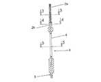
本発明によるところの器具は基本的に以下のものを含んで構成される:
・
第一に、
―スピンドルを通すチャックや他の回転駆動装置に固定できる手元部2と
―ネジ頭を受け入れるためのざぐりをこしらえることのできる錐カッター3を有した先端部と
―目盛り5を特色とする長さ方向に配された観察ポート4を備えた中央部と、
を特徴とする長尺の中空体1、
・
第二に、
中空体1の空孔内を軸方向に滑動できるような直径を有し、該中空体の観察ポート4において目視可能な目印手段7をその中間部に有した、先端部6が套管針であるスピンドル、The device according to the invention basically comprises the following:
・
Primarily,
-A
A long
・
Secondly,
The
且つ、該中空体1の手元部2は、中空体1およびこれに収容されたスピンドル6が、あるときには双方同時に、またあるときには該中空体のみが回転駆動されるように構成されている。Further, the
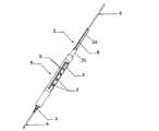
図に示された実施例によると、中空体1の手元部2の端部2aは複数のスリット穴8、例えば等間隔に配された4つのスリット穴を備えている。この設計により中空体1がスピンドルに圧着することが可能となり、中空体とスピンドルとの同時回転駆動をもたらす。According to the embodiment shown in the figure, the
図示された実施例によると、中空体1の手元部2はまた、前記端部2aを中空体の他の部分に連結するための部分2bを備えている。According to the illustrated embodiment, the
中空体の手元部のスリット入り端部2aの側壁面の成す直径を、隣にある前記手元部の無スリット部2bの直径より小さくすると有利である。この設計により一方から他方に指をスライドするとき凹凸により境界を感じることを可能とする。It is advantageous that the diameter formed by the side wall surface of the slit-containing
同様にして、中空部1の無スリット部2bの側壁面の有する直径は残りの部分より小さい。Similarly, the diameter of the side wall surface of the
本発明のプロセスによるなら、中空で、円筒形あるいは略円筒形の本体1は、目盛りを付した観察ポートを備えた平板状の中央部9を含んでいる。According to the process of the present invention, the hollow, cylindrical or substantially
図示された実施例の方法によるなら、観察ポート4は中空体1の中央平板部9の両面のうち一方に成形された長方形の長さ方向のスロットから成り、その少なくとも一方の縁側に目盛り5が目盛られている。According to the method of the illustrated embodiment, the
この目盛り5は、例えば、スロットの一方の縁側にミリ刻みで目盛られ、スロットの他方の縁側に5の倍数数字が印されている。The
中空体1の中央平板部9の両面にそれぞれ、一方の縁側に目盛りが振られた長さ方向スロット4を設けることは好ましく且つ有利であって、これにより本器具のとる向きにかかわらず孔の深さを読み取ることが可能となる。It is preferred and advantageous to provide a
図示された実施例によると、スピンドル6は、その中央部分で、その最先端6aから所定の距離の位置においてリング状のマーク7を有しており、このマークは着色されたリングであってもよく、あるいは好ましくはスピンドル本体に直接刻み込んだリングであり、これは観察ポート4越しに目視できるようにする。外科医はよってそのリングの位置に対応する目盛りを読むことができ、使用すべき外科用ネジの長さを決定することができる。According to the illustrated embodiment, the
前記スピンドル6が、その中央部分で、その最先端6aから所定の距離の位置において環状帯7aを有していると好ましく且つ有利であった、この帯は着色された被膜であってもよく、あるいは好ましくはスピンドル本体に直接刻み込んだ帯であり、これは観察ポート4越しに目視できるようにする。外科医はよってその刻印部と非刻印部との境目7bに対応する目盛りを読むことができ、使用すべき外科用ネジの長さを決定することができる。It was preferred and advantageous if the
前記スピンドル6は好ましくはその全長に亘り平滑な表面を有しており、ドリル先端6aは尖っている。The
中空体1の素材は必要な硬度を有した医学グレードの材料であればよく、例えば、ステンレス鋼や、チタンが挙げられる。The material of the
一方、スピンドル6の素材は必要な硬度を有した生体適合性材料であればよく、例えば、ステンレス鋼や、チタンが挙げられる。On the other hand, the material of the
本発明の器具は外科用中空ネジ、好ましくは圧縮ネジをその一部とする場合があり、これらはスピンドル6上を滑動しやすくまたスピンドル6の周りを回転しやすく、かといってスピンドル6との間に過度の遊びを有さないようにした程度の直径を有した軸孔を備えている。The instrument of the present invention may comprise a surgical hollow screw, preferably a compression screw, which is easy to slide on and rotate around the
一方、本発明の器具はまたねじ回し11をその一部とする場合があり、これは、前記外科用ネジ10を本発明の器具により予め穿たれた孔に装着するためのものであり、このねじ回し11はスピンドル6上を滑動しやすくまたスピンドル6の周りを回転しやすく、かといってスピンドル6との間に過度の遊びを有さないようにした程度の直径を有した軸孔を備えている。On the other hand, the instrument of the present invention may also include a
本発明に関わる器具を用いた骨ネジを装着するための手術手順によるならば、中空体1の先端からスピンドルの尖端がずいぶんと突出する程度にスピンドル6を中空体1内に差し込まねばならないが、同時に該中空体とスピンドルとは回転駆動装置のチャックによって互いに固定される。According to the surgical procedure for attaching the bone screw using the instrument according to the present invention, the
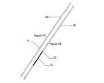
この設定は、例えばX線スクリーン等のスクリーン上でモニターされ、これによって外科医は骨組織内でのスピンドル6の進行を、その最先端6aが複数の骨片O、骨破片Fを通過し、ある骨の下方皮質部の内表面に達するまでを、目視することができる。This setting is monitored on a screen, for example an X-ray screen, so that the surgeon is in the progress of the
スピンドル6が前記所望の位置に達したなら、中空体1とスピンドル6との一体回転が停止され、前記回転駆動装置のチャックが緩められる。When the
中空体1はこのとき、錐カッター3よりなるその先端部が骨Oの上方皮質部に当たるところまでスピンドル6に沿って滑動自在である。At this time, the
外科医師はこのとき観察ポート4において斯く予め空けた孔の深さを読み、用いられるべきネジの長さを確実な精度を以って決定することができる。The surgeon can then read the depth of the previously drilled hole at the
当該医師は次に前記回転駆動装置のチャックを中空体1の手元部2の部分2bのレベルに位置することにより中空体1のみを締め止めする。モータは中空体1のみを回動させ、この錐カッターがネジ10の頭部を受け入れるためのざぐりCをこしらえる。The doctor then clamps only the
この錐込みが終わったなら、前記中空体1は骨に突き刺さったスピンドル6のみを残して撤去される。When this drilling is over, the
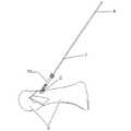
外科医は次に、軸孔10aを有し適度の長さを持った自己穿孔ネジ10をスピンドル6上に通し、これが骨組織に当たるまでスピンドル上を滑らせる。The surgeon then passes a self-
軸孔11aを有し以ってスピンドル6上を滑動且つ回転自在のねじ回し11によって、医師は当該外科用ネジ10を骨組織に穿ち込む。By means of a
こうして当該ネジは骨組織の中に装着され、ねじ回し11とスピンドル6は撤去される。Thus, the screw is mounted in the bone tissue, and the
1 中空部
2 手元部
3 錐カッター
4 観察ポート
5 目盛り
6 突き刺しスピンドル
7 目印手段
8 複数のスロット
9 平板状の中央部
10 外科用ネジ
11 ねじ回しDESCRIPTION OF
Claims (10)
Translated fromJapaneseある部分が、
チャックまたは他の回転駆動装置に自らを固定できる手元部(2)と、
ネジ頭を受け入れるためのざぐり部分をこしらえるための錐カッター(3)を有した先端部と、
目盛り(5)を有し長さ方向に配された観察ポート(4)を備えた中央部と、
を特徴とする長尺の中空体(1)より成り、
他の部分が、
前記中空体(1)の空孔内を軸方向に滑動できるような直径を呈し、前記中空体の前記観察ポート(4)において目視可能な表示手段(7)をその中間部に特徴として有した、突き刺しスピンドル(6)より成り、且つ、
前記中空体(1)の前記手元部(2)は、前記中空体(1)およびこれに収容された前記スピンドル(6)が、あるときは双方同時に、あるときは前記中空体のみが回転駆動されるようにしてなり、
前記中空体(1)の前記手元部(2)の端部(2a)は複数の縦スロット(8)を備えており、以って前記中空体は前記スピンドル(6)に同心締め固定可能であることを特徴とする装置。A device that helps to attach a screw to bone tissue, in particular a device used to join multiple bone fragments,
There is a part
A hand (2) that can fix itself to a chuck or other rotational drive;
A tip having a cone cutter (3) for handling a counterbore for receiving a screw head;
A central part with an observation port (4) having a scale (5) and arranged in the longitudinal direction;
Consisting of a long hollow body (1) characterized by
The other part is
The hollow body (1) has a diameter that allows it to slide in the axial direction in the air holes, and has a display means (7) that is visible in the observation port (4) of the hollow body as a feature in its middle part. Consists of a piercing spindle (6), and
When the hollow body (1) and the spindle (6) accommodated in the hollow body (1) are both present, the hollow portion (1) is rotated at the same time. To become
The end (2a) of the hand portion (2) of the hollow body (1) is provided with a plurality of vertical slots (8), so that the hollow body can be fixed concentrically to the spindle (6). A device characterized by being.
Applications Claiming Priority (3)
| Application Number | Priority Date | Filing Date | Title |
|---|---|---|---|
| FR09/00757 | 2009-02-19 | ||
| FR0900757AFR2942126B1 (en) | 2009-02-19 | 2009-02-19 | DEVICE FOR FACILITATING THE POSITIONING OF SCREWS IN BONE TISSUES AND INSTRUMENTATION BY APPLYING IN PARTICULAR TO PERFORM OSTEOSYNTHESIS OF BONE FRAGMENTS |
| PCT/FR2010/000063WO2010094846A1 (en) | 2009-02-19 | 2010-01-26 | Device to assist with the placement of screws in bone tissue and instrument applying said device, in particular for performing osteosynthesis of bone fragments |
Publications (2)
| Publication Number | Publication Date |
|---|---|
| JP2012517870A JP2012517870A (en) | 2012-08-09 |
| JP5699092B2true JP5699092B2 (en) | 2015-04-08 |
Family
ID=40717175
Family Applications (1)
| Application Number | Title | Priority Date | Filing Date |
|---|---|---|---|
| JP2011550615AExpired - Fee RelatedJP5699092B2 (en) | 2009-02-19 | 2010-01-26 | An instrument for mounting screws in bone tissue, and a tool for cooperating with the instrument, particularly for use in joint operations of multiple bone fragments |
Country Status (9)
| Country | Link |
|---|---|
| US (1) | US20120016373A1 (en) |
| EP (1) | EP2398404B1 (en) |
| JP (1) | JP5699092B2 (en) |
| AU (1) | AU2010215340B2 (en) |
| BR (1) | BRPI1006972A2 (en) |
| CA (1) | CA2750085C (en) |
| ES (1) | ES2608051T3 (en) |
| FR (1) | FR2942126B1 (en) |
| WO (1) | WO2010094846A1 (en) |
Families Citing this family (13)
| Publication number | Priority date | Publication date | Assignee | Title |
|---|---|---|---|---|
| US9427242B2 (en)* | 2011-09-08 | 2016-08-30 | Linvatec Corporation | Guide pin gauge |
| US9198704B2 (en) | 2012-07-18 | 2015-12-01 | Jmea Corporation | Impact and drive system for prosthesis deployment device |
| US12390258B2 (en) | 2012-07-18 | 2025-08-19 | Jmea Corporation | Methods and apparatus for implanting prostheses |
| WO2016035089A1 (en) | 2014-09-07 | 2016-03-10 | Resorbium Ltd. | Biocomposite orthopedic implant introducer assembly |
| EP3628249B1 (en) | 2014-12-26 | 2023-12-06 | Ossio Ltd | Continuous-fiber reinforced biocomposite medical implants |
| US10376367B2 (en) | 2015-07-02 | 2019-08-13 | First Ray, LLC | Orthopedic fasteners, instruments and methods |
| US10702290B2 (en) | 2015-11-02 | 2020-07-07 | First Ray, LLC | Orthopedic fastener, retainer, and guide |
| US11105613B2 (en)* | 2017-08-07 | 2021-08-31 | DePuy Synthes Products, Inc. | Universal direct measurement depth gauge |
| EP3773285A1 (en)* | 2018-04-12 | 2021-02-17 | Premia Spine Ltd. | K-wire depth measurement |
| US10835289B2 (en)* | 2018-10-18 | 2020-11-17 | Medos International Sàrl | Reamer instruments and related methods |
| IL294542A (en)* | 2021-07-19 | 2023-02-01 | Ossio Ltd | A device with a tube for inserting implants with an adjustable insertion depth |
| US12357326B2 (en) | 2021-09-15 | 2025-07-15 | Wright Medical Technology, Inc. | Combination depthsink instrument |
| EP4585169A1 (en)* | 2024-01-11 | 2025-07-16 | Fh Ortho | An instrumentation system for percutaneously fixing a headless bone screw into a patient's bone |
Family Cites Families (9)
| Publication number | Priority date | Publication date | Assignee | Title |
|---|---|---|---|---|
| FR2556377B1 (en)* | 1983-12-07 | 1986-10-24 | Bouygues Sa | BRIDGE MESH, BRIDGE TRUNK COMPRISING SUCH LATTICE AND METHOD FOR CONSTRUCTING THE BRIDGE |
| US5098435A (en)* | 1990-11-21 | 1992-03-24 | Alphatec Manufacturing Inc. | Cannula |
| US20030233098A1 (en)* | 2002-06-18 | 2003-12-18 | Stryker Spine | Variable depth drill guide |
| DE20300988U1 (en)* | 2003-01-23 | 2003-04-03 | stryker Trauma GmbH, 24232 Schönkirchen | Drilling tool for bone, especially the proximal femur |
| US7604643B2 (en)* | 2004-04-06 | 2009-10-20 | Synthes Usa, Llc | Adjustable tool for cannulated fasteners |
| US7491203B2 (en)* | 2005-02-14 | 2009-02-17 | Wright Medical Technology, Inc. | Instruments for bone screws |
| WO2008036309A2 (en) | 2006-09-19 | 2008-03-27 | Synthes (U.S.A) | Codified depth gauge |
| EP2120746A2 (en)* | 2007-01-05 | 2009-11-25 | TRANS1, Inc. | Percutaneous delivery of facet screws using depth control indicator |
| WO2008140748A1 (en)* | 2007-05-09 | 2008-11-20 | Ibalance Medical, Inc. | Method and apparatus for reconstructing a ligament and/or repairing cartilage, and for performing an open wedge, high tibial osteotomy |
- 2009
- 2009-02-19FRFR0900757Apatent/FR2942126B1/ennot_activeExpired - Fee Related
- 2010
- 2010-01-26EPEP10704397.8Apatent/EP2398404B1/ennot_activeNot-in-force
- 2010-01-26WOPCT/FR2010/000063patent/WO2010094846A1/enactiveApplication Filing
- 2010-01-26AUAU2010215340Apatent/AU2010215340B2/ennot_activeCeased
- 2010-01-26ESES10704397.8Tpatent/ES2608051T3/enactiveActive
- 2010-01-26CACA2750085Apatent/CA2750085C/ennot_activeExpired - Fee Related
- 2010-01-26JPJP2011550615Apatent/JP5699092B2/ennot_activeExpired - Fee Related
- 2010-01-26BRBRPI1006972Apatent/BRPI1006972A2/ennot_activeApplication Discontinuation
- 2010-01-26USUS13/146,145patent/US20120016373A1/ennot_activeAbandoned
Also Published As
| Publication number | Publication date |
|---|---|
| BRPI1006972A2 (en) | 2016-04-12 |
| EP2398404B1 (en) | 2016-10-05 |
| CA2750085A1 (en) | 2010-08-26 |
| ES2608051T3 (en) | 2017-04-05 |
| CA2750085C (en) | 2015-07-07 |
| AU2010215340A1 (en) | 2011-09-08 |
| AU2010215340B2 (en) | 2014-11-20 |
| FR2942126B1 (en) | 2011-03-25 |
| WO2010094846A1 (en) | 2010-08-26 |
| US20120016373A1 (en) | 2012-01-19 |
| EP2398404A1 (en) | 2011-12-28 |
| JP2012517870A (en) | 2012-08-09 |
| FR2942126A1 (en) | 2010-08-20 |
Similar Documents
| Publication | Publication Date | Title |
|---|---|---|
| JP5699092B2 (en) | An instrument for mounting screws in bone tissue, and a tool for cooperating with the instrument, particularly for use in joint operations of multiple bone fragments | |
| JP5770306B2 (en) | Surgical instruments | |
| US6665948B1 (en) | Drill bit penetration measurement system and method | |
| JP4486501B2 (en) | Adjustable length tap and method of tapping by drilling in bone | |
| US9427242B2 (en) | Guide pin gauge | |
| ES2620362T3 (en) | Medical devices with controlled depth actuators | |
| US9999444B2 (en) | Depth controlled Jamshidi needle | |
| EP3512440B1 (en) | Multiple head drill | |
| US20060106393A1 (en) | Bone reamer | |
| US20100145340A1 (en) | Introducer Tool for Bone Measurement | |
| EP2757989B1 (en) | Surgical instrument | |
| EP2978375B1 (en) | Tunnel gage | |
| EP0984840A1 (en) | Drilling guide and measuring instrumentation | |
| JP2007508050A (en) | Modular guidance portal | |
| US20170020534A1 (en) | Fluted bone awl and method of use | |
| KR20210005716A (en) | Motorized surgical drill having a transducer assembly comprising at least two rotational sensor devices for use in determining the bore depth of a drilled hole | |
| EP2879587B1 (en) | Depth controlled jamshidi needle | |
| JP2004016819A (en) | Implant system and alignment device therefor | |
| JP2023545391A (en) | Devices and systems for bone fixation based on nails | |
| KR20130108993A (en) | Instruments for mini-invasive spinal column surgery and uses thereof | |
| Palmer | Interlocking nails: the gadgetry and surgical methods. |
Legal Events
| Date | Code | Title | Description |
|---|---|---|---|
| A621 | Written request for application examination | Free format text:JAPANESE INTERMEDIATE CODE: A621 Effective date:20121211 | |
| A977 | Report on retrieval | Free format text:JAPANESE INTERMEDIATE CODE: A971007 Effective date:20131018 | |
| A131 | Notification of reasons for refusal | Free format text:JAPANESE INTERMEDIATE CODE: A131 Effective date:20131111 | |
| A521 | Request for written amendment filed | Free format text:JAPANESE INTERMEDIATE CODE: A523 Effective date:20140210 | |
| A711 | Notification of change in applicant | Free format text:JAPANESE INTERMEDIATE CODE: A711 Effective date:20140311 | |
| A521 | Request for written amendment filed | Free format text:JAPANESE INTERMEDIATE CODE: A821 Effective date:20140311 | |
| A131 | Notification of reasons for refusal | Free format text:JAPANESE INTERMEDIATE CODE: A131 Effective date:20140604 | |
| A521 | Request for written amendment filed | Free format text:JAPANESE INTERMEDIATE CODE: A523 Effective date:20140904 | |
| TRDD | Decision of grant or rejection written | ||
| A01 | Written decision to grant a patent or to grant a registration (utility model) | Free format text:JAPANESE INTERMEDIATE CODE: A01 Effective date:20150126 | |
| A61 | First payment of annual fees (during grant procedure) | Free format text:JAPANESE INTERMEDIATE CODE: A61 Effective date:20150216 | |
| R150 | Certificate of patent or registration of utility model | Ref document number:5699092 Country of ref document:JP Free format text:JAPANESE INTERMEDIATE CODE: R150 | |
| R250 | Receipt of annual fees | Free format text:JAPANESE INTERMEDIATE CODE: R250 | |
| LAPS | Cancellation because of no payment of annual fees |