JP5697694B2 - Device for treating morbid obesity using hydrogels - Google Patents
Device for treating morbid obesity using hydrogelsDownload PDFInfo
- Publication number
- JP5697694B2 JP5697694B2JP2012555021AJP2012555021AJP5697694B2JP 5697694 B2JP5697694 B2JP 5697694B2JP 2012555021 AJP2012555021 AJP 2012555021AJP 2012555021 AJP2012555021 AJP 2012555021AJP 5697694 B2JP5697694 B2JP 5697694B2
- Authority
- JP
- Japan
- Prior art keywords
- hydrogel
- fluid
- forming device
- restriction
- patient
- Prior art date
- Legal status (The legal status is an assumption and is not a legal conclusion. Google has not performed a legal analysis and makes no representation as to the accuracy of the status listed.)
- Expired - Fee Related
Links
- 239000000017hydrogelSubstances0.000titleclaimsdescription294
- 208000008589ObesityDiseases0.000titledescription19
- 208000001022morbid obesityDiseases0.000titledescription19
- 208000012696congenital leptin deficiencyDiseases0.000titledescription18
- 239000012530fluidSubstances0.000claimsdescription176
- 230000002496gastric effectEffects0.000claimsdescription160
- 230000004044responseEffects0.000claimsdescription63
- 230000037406food intakeEffects0.000claimsdescription28
- 238000004891communicationMethods0.000claimsdescription20
- 235000012631food intakeNutrition0.000claimsdescription20
- 230000008961swellingEffects0.000claimsdescription12
- 210000004051gastric juiceAnatomy0.000claimsdescription8
- 210000001035gastrointestinal tractAnatomy0.000claimsdescription6
- 210000003484anatomyAnatomy0.000claimsdescription4
- 230000004888barrier functionEffects0.000claimsdescription4
- 238000002513implantationMethods0.000claimsdescription4
- 238000001514detection methodMethods0.000claims2
- 210000002784stomachAnatomy0.000description90
- 239000000463materialSubstances0.000description33
- 235000013305foodNutrition0.000description29
- 238000000034methodMethods0.000description27
- 239000008188pelletSubstances0.000description25
- 208000021302gastroesophageal reflux diseaseDiseases0.000description21
- 230000007423decreaseEffects0.000description15
- 210000001198duodenumAnatomy0.000description14
- 230000007246mechanismEffects0.000description14
- 235000005686eatingNutrition0.000description13
- 210000003238esophagusAnatomy0.000description13
- 230000008859changeEffects0.000description12
- 210000003236esophagogastric junctionAnatomy0.000description11
- 238000011282treatmentMethods0.000description11
- 238000001802infusionMethods0.000description10
- 230000004048modificationEffects0.000description10
- 238000012986modificationMethods0.000description10
- 201000010099diseaseDiseases0.000description9
- 208000037265diseases, disorders, signs and symptomsDiseases0.000description9
- 229920000642polymerPolymers0.000description9
- 230000002378acidificating effectEffects0.000description8
- 239000000853adhesiveSubstances0.000description8
- 230000001070adhesive effectEffects0.000description8
- 238000010586diagramMethods0.000description7
- 239000000178monomerSubstances0.000description7
- 235000015097nutrientsNutrition0.000description7
- 239000003814drugSubstances0.000description6
- 229940079593drugDrugs0.000description6
- 239000007788liquidSubstances0.000description6
- 239000011148porous materialSubstances0.000description6
- 230000008569processEffects0.000description6
- 239000000126substanceSubstances0.000description6
- FAPWRFPIFSIZLT-UHFFFAOYSA-MSodium chlorideChemical compound[Na+].[Cl-]FAPWRFPIFSIZLT-UHFFFAOYSA-M0.000description5
- 230000006378damageEffects0.000description5
- 239000000499gelSubstances0.000description5
- -1hydrogen ionsChemical class0.000description5
- 238000002347injectionMethods0.000description5
- 239000007924injectionSubstances0.000description5
- 230000035479physiological effects, processes and functionsEffects0.000description5
- 239000011780sodium chlorideSubstances0.000description5
- 230000000694effectsEffects0.000description4
- 229920001296polysiloxanePolymers0.000description4
- 230000005855radiationEffects0.000description4
- 230000002441reversible effectEffects0.000description4
- 102000004190EnzymesHuman genes0.000description3
- 108090000790EnzymesProteins0.000description3
- WOBHKFSMXKNTIM-UHFFFAOYSA-NHydroxyethyl methacrylateChemical compoundCC(=C)C(=O)OCCOWOBHKFSMXKNTIM-UHFFFAOYSA-N0.000description3
- 239000002253acidSubstances0.000description3
- 238000013019agitationMethods0.000description3
- 238000004140cleaningMethods0.000description3
- 102000038379digestive enzymesHuman genes0.000description3
- 108091007734digestive enzymesProteins0.000description3
- 230000030135gastric motilityEffects0.000description3
- 125000004435hydrogen atomChemical group[H]*0.000description3
- 239000004033plasticSubstances0.000description3
- 229920003023plasticPolymers0.000description3
- 239000005020polyethylene terephthalateSubstances0.000description3
- 238000002360preparation methodMethods0.000description3
- 230000004043responsivenessEffects0.000description3
- 238000001356surgical procedureMethods0.000description3
- 229920002818(Hydroxyethyl)methacrylatePolymers0.000description2
- BQCIDUSAKPWEOX-UHFFFAOYSA-N1,1-DifluoroetheneChemical compoundFC(F)=CBQCIDUSAKPWEOX-UHFFFAOYSA-N0.000description2
- 208000034347Faecal incontinenceDiseases0.000description2
- WQZGKKKJIJFFOK-GASJEMHNSA-NGlucoseNatural productsOC[C@H]1OC(O)[C@H](O)[C@@H](O)[C@@H]1OWQZGKKKJIJFFOK-GASJEMHNSA-N0.000description2
- 206010021639IncontinenceDiseases0.000description2
- 206010046543Urinary incontinenceDiseases0.000description2
- 150000001252acrylic acid derivativesChemical class0.000description2
- NIXOWILDQLNWCW-UHFFFAOYSA-Nacrylic acid groupChemical groupC(C=C)(=O)ONIXOWILDQLNWCW-UHFFFAOYSA-N0.000description2
- 125000000129anionic groupChemical group0.000description2
- 230000006399behaviorEffects0.000description2
- 239000013626chemical specieSubstances0.000description2
- 238000010276constructionMethods0.000description2
- 230000008602contractionEffects0.000description2
- 229920001577copolymerPolymers0.000description2
- 201000006549dyspepsiaDiseases0.000description2
- 230000005684electric fieldEffects0.000description2
- 229920002313fluoropolymerPolymers0.000description2
- 239000004811fluoropolymerSubstances0.000description2
- 235000019525fullnessNutrition0.000description2
- 239000008103glucoseSubstances0.000description2
- 208000024798heartburnDiseases0.000description2
- HCDGVLDPFQMKDK-UHFFFAOYSA-NhexafluoropropyleneChemical groupFC(F)=C(F)C(F)(F)FHCDGVLDPFQMKDK-UHFFFAOYSA-N0.000description2
- 239000002184metalSubstances0.000description2
- 229910052751metalInorganic materials0.000description2
- 235000015816nutrient absorptionNutrition0.000description2
- 235000006286nutrient intakeNutrition0.000description2
- 230000002093peripheral effectEffects0.000description2
- 230000004962physiological conditionEffects0.000description2
- 229920000728polyesterPolymers0.000description2
- 229920001223polyethylene glycolPolymers0.000description2
- 229920000139polyethylene terephthalatePolymers0.000description2
- 230000001007puffing effectEffects0.000description2
- 230000036186satietyEffects0.000description2
- 235000019627satietyNutrition0.000description2
- BFKJFAAPBSQJPD-UHFFFAOYSA-NtetrafluoroetheneChemical groupFC(F)=C(F)FBFKJFAAPBSQJPD-UHFFFAOYSA-N0.000description2
- 210000001519tissueAnatomy0.000description2
- 230000001960triggered effectEffects0.000description2
- XLYOFNOQVPJJNP-UHFFFAOYSA-NwaterSubstancesOXLYOFNOQVPJJNP-UHFFFAOYSA-N0.000description2
- 230000004580weight lossEffects0.000description2
- QRIMLDXJAPZHJE-UHFFFAOYSA-N2,3-dihydroxypropyl 2-methylprop-2-enoateChemical compoundCC(=C)C(=O)OCC(O)COQRIMLDXJAPZHJE-UHFFFAOYSA-N0.000description1
- OWPUOLBODXJOKH-UHFFFAOYSA-N2,3-dihydroxypropyl prop-2-enoateChemical compoundOCC(O)COC(=O)C=COWPUOLBODXJOKH-UHFFFAOYSA-N0.000description1
- SMZOUWXMTYCWNB-UHFFFAOYSA-N2-(2-methoxy-5-methylphenyl)ethanamineChemical compoundCOC1=CC=C(C)C=C1CCNSMZOUWXMTYCWNB-UHFFFAOYSA-N0.000description1
- JKNCOURZONDCGV-UHFFFAOYSA-N2-(dimethylamino)ethyl 2-methylprop-2-enoateChemical compoundCN(C)CCOC(=O)C(C)=CJKNCOURZONDCGV-UHFFFAOYSA-N0.000description1
- OMIGHNLMNHATMP-UHFFFAOYSA-N2-hydroxyethyl prop-2-enoateChemical compoundOCCOC(=O)C=COMIGHNLMNHATMP-UHFFFAOYSA-N0.000description1
- 241000894006BacteriaSpecies0.000description1
- 102000008186CollagenHuman genes0.000description1
- 108010035532CollagenProteins0.000description1
- 229920001651CyanoacrylatePolymers0.000description1
- 229920004934Dacron®Polymers0.000description1
- 208000008279Dumping SyndromeDiseases0.000description1
- IAYPIBMASNFSPL-UHFFFAOYSA-NEthylene oxideChemical compoundC1CO1IAYPIBMASNFSPL-UHFFFAOYSA-N0.000description1
- CERQOIWHTDAKMF-UHFFFAOYSA-NMethacrylic acidChemical compoundCC(=C)C(O)=OCERQOIWHTDAKMF-UHFFFAOYSA-N0.000description1
- WHNWPMSKXPGLAX-UHFFFAOYSA-NN-Vinyl-2-pyrrolidoneChemical compoundC=CN1CCCC1=OWHNWPMSKXPGLAX-UHFFFAOYSA-N0.000description1
- 206010033799ParalysisDiseases0.000description1
- 229920002845Poly(methacrylic acid)Polymers0.000description1
- 239000004698PolyethyleneSubstances0.000description1
- 239000004743PolypropyleneSubstances0.000description1
- 208000032395Post gastric surgery syndromeDiseases0.000description1
- 229920002472StarchPolymers0.000description1
- RTAQQCXQSZGOHL-UHFFFAOYSA-NTitaniumChemical compound[Ti]RTAQQCXQSZGOHL-UHFFFAOYSA-N0.000description1
- 229920000690TyvekPolymers0.000description1
- 239000004775TyvekSubstances0.000description1
- 208000027418Wounds and injuryDiseases0.000description1
- 230000003187abdominal effectEffects0.000description1
- 238000010521absorption reactionMethods0.000description1
- 150000003926acrylamidesChemical class0.000description1
- 150000001298alcoholsChemical class0.000description1
- 125000003277amino groupChemical group0.000description1
- 230000008901benefitEffects0.000description1
- 230000015572biosynthetic processEffects0.000description1
- 210000004204blood vesselAnatomy0.000description1
- 230000003139buffering effectEffects0.000description1
- 239000004067bulking agentSubstances0.000description1
- 150000001735carboxylic acidsChemical group0.000description1
- 125000002091cationic groupChemical group0.000description1
- 238000006243chemical reactionMethods0.000description1
- 229920001436collagenPolymers0.000description1
- NLCKLZIHJQEMCU-UHFFFAOYSA-Ncyano prop-2-enoateChemical classC=CC(=O)OC#NNLCKLZIHJQEMCU-UHFFFAOYSA-N0.000description1
- 230000001419dependent effectEffects0.000description1
- 230000005595deprotonationEffects0.000description1
- 238000010537deprotonation reactionMethods0.000description1
- 210000002249digestive systemAnatomy0.000description1
- 230000010339dilationEffects0.000description1
- 238000012377drug deliveryMethods0.000description1
- 235000006694eating habitsNutrition0.000description1
- 230000005611electricityEffects0.000description1
- 230000007613environmental effectEffects0.000description1
- 210000003195fasciaAnatomy0.000description1
- 125000001153fluoro groupChemical groupF*0.000description1
- 229920001973fluoroelastomerPolymers0.000description1
- 229920001002functional polymerPolymers0.000description1
- 239000007789gasSubstances0.000description1
- 210000004211gastric acidAnatomy0.000description1
- 230000027119gastric acid secretionEffects0.000description1
- 238000000227grindingMethods0.000description1
- 229910052739hydrogenInorganic materials0.000description1
- 239000001257hydrogenSubstances0.000description1
- GPRLSGONYQIRFK-UHFFFAOYSA-NhydronChemical group[H+]GPRLSGONYQIRFK-UHFFFAOYSA-N0.000description1
- 201000001881impotenceDiseases0.000description1
- 238000011065in-situ storageMethods0.000description1
- 230000005764inhibitory processEffects0.000description1
- 208000014674injuryDiseases0.000description1
- 210000005027intestinal barrierAnatomy0.000description1
- 230000007358intestinal barrier functionEffects0.000description1
- 239000012948isocyanateSubstances0.000description1
- 150000002513isocyanatesChemical class0.000description1
- 210000000111lower esophageal sphincterAnatomy0.000description1
- 239000011159matrix materialSubstances0.000description1
- 150000002739metalsChemical class0.000description1
- FQPSGWSUVKBHSU-UHFFFAOYSA-NmethacrylamideChemical compoundCC(=C)C(N)=OFQPSGWSUVKBHSU-UHFFFAOYSA-N0.000description1
- 238000012544monitoring processMethods0.000description1
- 230000004899motilityEffects0.000description1
- 210000003205muscleAnatomy0.000description1
- 230000003387muscularEffects0.000description1
- 229940088644n,n-dimethylacrylamideDrugs0.000description1
- YLGYACDQVQQZSW-UHFFFAOYSA-Nn,n-dimethylprop-2-enamideChemical compoundCN(C)C(=O)C=CYLGYACDQVQQZSW-UHFFFAOYSA-N0.000description1
- 230000007935neutral effectEffects0.000description1
- 229910001000nickel titaniumInorganic materials0.000description1
- 235000016709nutritionNutrition0.000description1
- 230000035764nutritionEffects0.000description1
- 235000020824obesityNutrition0.000description1
- 150000007524organic acidsChemical class0.000description1
- XLYOFNOQVPJJNP-UHFFFAOYSA-OoxoniumChemical compound[OH3+]XLYOFNOQVPJJNP-UHFFFAOYSA-O0.000description1
- 125000001997phenyl groupChemical group[H]C1=C([H])C([H])=C(*)C([H])=C1[H]0.000description1
- 230000037081physical activityEffects0.000description1
- 230000035790physiological processes and functionsEffects0.000description1
- 229920000573polyethylenePolymers0.000description1
- 229920000098polyolefinPolymers0.000description1
- 229920001155polypropylenePolymers0.000description1
- 239000004810polytetrafluoroethyleneSubstances0.000description1
- 229920001343polytetrafluoroethylenePolymers0.000description1
- 230000002265preventionEffects0.000description1
- 210000001187pylorusAnatomy0.000description1
- 238000010992refluxMethods0.000description1
- 230000029058respiratory gaseous exchangeEffects0.000description1
- 230000035440response to pHEffects0.000description1
- 229920002379silicone rubberPolymers0.000description1
- 239000000243solutionSubstances0.000description1
- 239000008107starchSubstances0.000description1
- 235000019698starchNutrition0.000description1
- 230000001954sterilising effectEffects0.000description1
- 238000004659sterilization and disinfectionMethods0.000description1
- 210000001562sternumAnatomy0.000description1
- 238000003786synthesis reactionMethods0.000description1
- 229920001897terpolymerPolymers0.000description1
- 239000010936titaniumSubstances0.000description1
- 229910052719titaniumInorganic materials0.000description1
- 210000001942upper esophageal sphincterAnatomy0.000description1
Images


Classifications
- A—HUMAN NECESSITIES
- A61—MEDICAL OR VETERINARY SCIENCE; HYGIENE
- A61F—FILTERS IMPLANTABLE INTO BLOOD VESSELS; PROSTHESES; DEVICES PROVIDING PATENCY TO, OR PREVENTING COLLAPSING OF, TUBULAR STRUCTURES OF THE BODY, e.g. STENTS; ORTHOPAEDIC, NURSING OR CONTRACEPTIVE DEVICES; FOMENTATION; TREATMENT OR PROTECTION OF EYES OR EARS; BANDAGES, DRESSINGS OR ABSORBENT PADS; FIRST-AID KITS
- A61F5/00—Orthopaedic methods or devices for non-surgical treatment of bones or joints; Nursing devices ; Anti-rape devices
- A61F5/0003—Apparatus for the treatment of obesity; Anti-eating devices
- A61F5/0013—Implantable devices or invasive measures
- A61F5/005—Gastric bands
- A61F5/0053—Gastric bands remotely adjustable
- A61F5/0056—Gastric bands remotely adjustable using injection ports
- A—HUMAN NECESSITIES
- A61—MEDICAL OR VETERINARY SCIENCE; HYGIENE
- A61F—FILTERS IMPLANTABLE INTO BLOOD VESSELS; PROSTHESES; DEVICES PROVIDING PATENCY TO, OR PREVENTING COLLAPSING OF, TUBULAR STRUCTURES OF THE BODY, e.g. STENTS; ORTHOPAEDIC, NURSING OR CONTRACEPTIVE DEVICES; FOMENTATION; TREATMENT OR PROTECTION OF EYES OR EARS; BANDAGES, DRESSINGS OR ABSORBENT PADS; FIRST-AID KITS
- A61F5/00—Orthopaedic methods or devices for non-surgical treatment of bones or joints; Nursing devices ; Anti-rape devices
- A61F5/0003—Apparatus for the treatment of obesity; Anti-eating devices
- A61F5/0013—Implantable devices or invasive measures
- A61F5/003—Implantable devices or invasive measures inflatable
- A—HUMAN NECESSITIES
- A61—MEDICAL OR VETERINARY SCIENCE; HYGIENE
- A61F—FILTERS IMPLANTABLE INTO BLOOD VESSELS; PROSTHESES; DEVICES PROVIDING PATENCY TO, OR PREVENTING COLLAPSING OF, TUBULAR STRUCTURES OF THE BODY, e.g. STENTS; ORTHOPAEDIC, NURSING OR CONTRACEPTIVE DEVICES; FOMENTATION; TREATMENT OR PROTECTION OF EYES OR EARS; BANDAGES, DRESSINGS OR ABSORBENT PADS; FIRST-AID KITS
- A61F5/00—Orthopaedic methods or devices for non-surgical treatment of bones or joints; Nursing devices ; Anti-rape devices
- A61F5/0003—Apparatus for the treatment of obesity; Anti-eating devices
- A61F5/0013—Implantable devices or invasive measures
- A61F5/0036—Intragastrical devices
- A—HUMAN NECESSITIES
- A61—MEDICAL OR VETERINARY SCIENCE; HYGIENE
- A61F—FILTERS IMPLANTABLE INTO BLOOD VESSELS; PROSTHESES; DEVICES PROVIDING PATENCY TO, OR PREVENTING COLLAPSING OF, TUBULAR STRUCTURES OF THE BODY, e.g. STENTS; ORTHOPAEDIC, NURSING OR CONTRACEPTIVE DEVICES; FOMENTATION; TREATMENT OR PROTECTION OF EYES OR EARS; BANDAGES, DRESSINGS OR ABSORBENT PADS; FIRST-AID KITS
- A61F5/00—Orthopaedic methods or devices for non-surgical treatment of bones or joints; Nursing devices ; Anti-rape devices
- A61F5/0003—Apparatus for the treatment of obesity; Anti-eating devices
- A61F5/0013—Implantable devices or invasive measures
- A61F5/005—Gastric bands
- A61F5/0053—Gastric bands remotely adjustable
- A—HUMAN NECESSITIES
- A61—MEDICAL OR VETERINARY SCIENCE; HYGIENE
- A61F—FILTERS IMPLANTABLE INTO BLOOD VESSELS; PROSTHESES; DEVICES PROVIDING PATENCY TO, OR PREVENTING COLLAPSING OF, TUBULAR STRUCTURES OF THE BODY, e.g. STENTS; ORTHOPAEDIC, NURSING OR CONTRACEPTIVE DEVICES; FOMENTATION; TREATMENT OR PROTECTION OF EYES OR EARS; BANDAGES, DRESSINGS OR ABSORBENT PADS; FIRST-AID KITS
- A61F5/00—Orthopaedic methods or devices for non-surgical treatment of bones or joints; Nursing devices ; Anti-rape devices
- A61F5/0003—Apparatus for the treatment of obesity; Anti-eating devices
- A61F5/0013—Implantable devices or invasive measures
- A61F5/0076—Implantable devices or invasive measures preventing normal digestion, e.g. Bariatric or gastric sleeves
- A—HUMAN NECESSITIES
- A61—MEDICAL OR VETERINARY SCIENCE; HYGIENE
- A61F—FILTERS IMPLANTABLE INTO BLOOD VESSELS; PROSTHESES; DEVICES PROVIDING PATENCY TO, OR PREVENTING COLLAPSING OF, TUBULAR STRUCTURES OF THE BODY, e.g. STENTS; ORTHOPAEDIC, NURSING OR CONTRACEPTIVE DEVICES; FOMENTATION; TREATMENT OR PROTECTION OF EYES OR EARS; BANDAGES, DRESSINGS OR ABSORBENT PADS; FIRST-AID KITS
- A61F13/00—Bandages or dressings; Absorbent pads
- A61F2013/00361—Plasters
- A61F2013/00655—Plasters adhesive
- A61F2013/00676—Plasters adhesive hydrogel
Landscapes
- Health & Medical Sciences (AREA)
- Child & Adolescent Psychology (AREA)
- Obesity (AREA)
- Nursing (AREA)
- Orthopedic Medicine & Surgery (AREA)
- Engineering & Computer Science (AREA)
- Biomedical Technology (AREA)
- Heart & Thoracic Surgery (AREA)
- Vascular Medicine (AREA)
- Life Sciences & Earth Sciences (AREA)
- Animal Behavior & Ethology (AREA)
- General Health & Medical Sciences (AREA)
- Public Health (AREA)
- Veterinary Medicine (AREA)
- Surgical Instruments (AREA)
Description
Translated fromJapanese病的肥満を治療するために、様々なシステム及び装置が作製され、使用されてきた。そうしたいくつかのシステム及び装置には、食道から胃の中への食物の流れを制限するように操作可能な、調節可能な胃バンドシステムが含まれる。一部の胃バンドは、胃食道接合部の直下の胃を包囲する固定された複数の終点を有する、流体で満たされたエラストマーブラダ(elastomeric bladder)を含む。ブラダに流体が加えられると、バンドは胃に対して拡張して、食物摂取量制限部又は小孔を胃の中に形成する。制限部を崩壊するためには、プラダから流体を除去する。胃バンドの例は、その開示が参照により本明細書に組み込まれる米国特許第7,416,528号、発明の名称「Latching Device for Gastric Band」(2008年8月26日発行)、及びにその開示が参照により本明細書に組み込まれる米国特許出願公開第2006/0211914号、発明の名称「System and Method for Determining Implanted Device Positioning and Obtaining Pressure Data」(2006年9月21日発行)に開示されている。流体は、ブラダ(bladder)と連結されている埋め込まれた注入ポートを介して流体を注入するための注射器及び針(例えば、ヒューバー針)を使用して、ブラダに加えられてもよい。同様に、流体は、埋め込まれた注入ポートを介して流体を引き抜くための注射器及び針を使用して、ブラダから除去されてもよい。 Various systems and devices have been made and used to treat morbid obesity. Some such systems and devices include adjustable gastric band systems that are operable to limit the flow of food from the esophagus into the stomach. Some gastric bands include a fluid-filled elastomeric bladder with a plurality of fixed end points surrounding the stomach directly below the gastroesophageal junction. As fluid is added to the bladder, the band expands against the stomach to form a food intake restriction or stoma in the stomach. In order to collapse the restriction, the fluid is removed from the prada. Examples of gastric bands include US Pat. No. 7,416,528, the title of the invention “Latching Device for Gastric Band” (issued August 26, 2008), and US Patent Application Publication No. 2006/0211914, the disclosure of which is incorporated herein by reference, entitled “System and Method for Determining Implemented Device Positioning and Obtaining Pressure Data” (published on Sep. 21, 2006) Yes. The fluid may be added to the bladder using a syringe and a needle (eg, a Huber needle) for injecting fluid through an implanted infusion port that is coupled to the bladder. Similarly, fluid may be removed from the bladder using a syringe and needle to draw fluid through the implanted infusion port.
胃バンドシステムは、注入ポートに加えて又は注入ポートに代わるものとして、胃バンドのブラダ内の流体レベルを調節するために使用されるポンプを含んでもよい。ポンプを組み込んだ胃バンドシステムの例は、その開示が参照により本明細書に組み込まれる米国特許第7,390,294号、発明の名称「Piezo Electrically Driven Bellows Infuser for Hydraulically Controlling an Adjustable Gastric Band」(2008年6月24日発行)に記載されている。このようなシステムの他の例は、その開示が参照により本明細書に組み込まれる米国特許第7,351,240号、発明の名称「Thermodynamically Driven Reversible Infuser Pump for Use as a Remotely Controlled Gastric Band」(2008年4月1日発行)に記載されている。 The gastric band system may include a pump that is used to regulate the fluid level in the gastric band bladder in addition to or as an alternative to the infusion port. An example of a gastric band system incorporating a pump is described in US Pat. No. 7,390,294, the disclosure of which is hereby incorporated by reference, “Piezo Electrically Drawn Bellows Informer for Hybrid Controlling An Adjustable”. Issued on June 24, 2008). Another example of such a system is US Pat. No. 7,351,240, the disclosure of which is incorporated herein by reference, the title of “Thermodynamically Driven Reversible Infused Pump for Use as a Remotely Controlled Gas”. Issued on April 1, 2008).
病的肥満又は他の疾患を治療するためのその他の方法及び装置としては、胃スリーブ、胃バルブ、空間占有デバイス(space occupying device)、及び膨化装置(bulking device)の使用が挙げられる。胃スリーブは、胃の外部の周囲に設置されるのではなく、胃の内部(又は胃腸管内の他の場所)内に設置されてもよい。胃スリーブのいくつかのタイプは、胃腸管内(例えば、十二指腸内)への栄養素の吸収を制限するように構成されてもよい。胃スリーブの例は、その開示が参照により本明細書に組み込まれる米国特許第7,037,344号、発明の名称「Apparatus and Methods for Treatment of Morbid Obesity」(2006年5月2日発行)に開示されている。 Other methods and devices for treating morbid obesity or other diseases include the use of gastric sleeves, gastric valves, space occupying devices, and bulking devices. Rather than being placed around the exterior of the stomach, the stomach sleeve may be placed within the stomach (or elsewhere in the gastrointestinal tract). Some types of gastric sleeves may be configured to limit the absorption of nutrients into the gastrointestinal tract (eg, within the duodenum). Examples of gastric sleeves can be found in US Pat. No. 7,037,344, the disclosure of which is hereby incorporated by reference, “Apparatus and Methods for Treatment of Morbid Obesity” (issued May 2, 2006). It is disclosed.
胃バルブは、胃の内部又は外部(例えば、食道又は幽門等)に設置されてもよく、胃の中への食物の流れを選択的に制限することができる。胃バンドと同様に、胃バルブによってもたらされる制限部の程度は、少なくとも一部には、胃バルブの1つ又は2つ以上の可膨張部分内の流体の量に基づく。そのような流体レベルは、様々な方法で調節され得る。胃バルブの例は、その開示が参照により本明細書に組み込まれる米国出願公開第2006/0235448号、発明の名称「Artificial Gastric Valve」(2006年10月19日公開)に開示されている。 The gastric valve may be placed inside or outside the stomach (eg, the esophagus or pylorus) and can selectively restrict the flow of food into the stomach. As with the gastric band, the degree of restriction provided by the gastric valve is based, at least in part, on the amount of fluid in one or more inflatable portions of the gastric valve. Such fluid levels can be adjusted in various ways. Examples of gastric valves are disclosed in US Application Publication No. 2006/0235448, entitled “Artificial Gastric Valve” (published 19 October 2006), the disclosure of which is incorporated herein by reference.
空間占有デバイスは、胃に埋め込まれるバルーンなどの装置であり得る。空間占有バルーンは実質的に難消化性であり得、胃の中に存在することによって、比較的早期の満腹感をもたらすことができる。バルーンが占有する空間の量は、少なくとも一部には、バルーンの中の流体量に基づくことができる。そのような流体レベルは、様々な方法で調節され得る。空間占有デバイスは、胃の中の空間を占有することに加えて、食物の通過のための比較的狭い通路を提供することによって胃の中に制限部を形成することすら可能であり、該通路の寸法は、少なくとも一部には、空間占有デバイスの中の流体量に基づく。空間占有デバイスの例は、その開示が参照により本明細書に組み込まれる米国出願公開第2008/0103593号、発明の名称「Use of Biosurgical Adhesive on Inflatable Device for Gastric Restriction」(2008年5月1日公開)に開示されている。 The space occupying device may be a device such as a balloon implanted in the stomach. Space-occupying balloons can be substantially indigestible and can be present in the stomach to provide a relatively early feeling of fullness. The amount of space occupied by the balloon can be based at least in part on the amount of fluid in the balloon. Such fluid levels can be adjusted in various ways. In addition to occupying the space in the stomach, the space occupancy device can even form a restriction in the stomach by providing a relatively narrow passage for the passage of food, the passage The dimensions of are based at least in part on the amount of fluid in the space occupying device. An example of a space occupying device is US Application Publication No. 2008/0103593, the disclosure of which is hereby incorporated by reference, “Use of Biosurgical Adhesive Device for Gastronomy Restriction” (published May 1, 2008). ).
膨化装置には、胃の層間に設置されて胃の内部容積又は容量を低減する装置が含まれる。空間占有デバイスと同様に、胃の中に膨化装置が存在することによって、比較的早期の満腹感をもたらすことができ、膨化装置の存在によって低減される容積の量は、少なくとも一部には、膨化装置の中の流体量に基づくことができる。これに加えて又は代替として、膨化装置は、胃の中への食物の流れを制限するために、食道の層の間に設置されてもよい。膨化装置として使用される接着剤の例は、その開示が参照により本明細書に組み込まれる米国出願公開第2008/0154228号、発明の名称「Use of Biosurgical Adhesive as Bulking Agent」(2008年6月26日公開)に開示されているが、そのような接着剤は、1つ又は2つ以上の可膨張部と交換可能又は1つ又は2つ以上の可膨張部で補足可能であることを理解すべきである。膨化の追加の例は、その開示が参照により本明細書に組み込まれる米国出願公開第2006/0247768号、発明の名称「Bulking of Upper Esophageal Sphincter for Treatment of Obesity」(2006年11月2日公開)に開示されている。 Inflation devices include devices that are placed between stomach layers to reduce the internal volume or volume of the stomach. Similar to the space occupancy device, the presence of the inflation device in the stomach can provide a relatively early feeling of fullness and the amount of volume reduced by the presence of the inflation device is at least in part: It can be based on the amount of fluid in the expansion device. In addition or alternatively, a puffing device may be placed between the layers of the esophagus to limit the flow of food into the stomach. An example of an adhesive used as a puffing device is disclosed in U.S. Application Publication No. 2008/0154228, whose title is “Use of Biosurgical Adhesive as Bulking Agent” (June 26, 2008), the disclosure of which is incorporated herein by reference. It is understood that such an adhesive is interchangeable with one or more inflatable parts or can be supplemented with one or more inflatable parts. Should. An additional example of swelling is U.S. Application Publication No. 2006/0247768, the disclosure of which is incorporated herein by reference, the title "Bulking of Upper Esophageal Sphincter for Treatment of Obesity" (published November 2, 2006). Is disclosed.
病的肥満又は他の疾患を治療するための前述の装置には、流体で充填された部材がなくてもよく、その結果、装置は、装置の中の流体の量又は圧力を調節するのではない何らかの方法で調節され得ることもまた理解すべきである。例えば、かかる装置は、機械又は電気機械的な、非液体ベースで調節されてもよい。 The aforementioned devices for treating morbid obesity or other diseases may be free of fluid-filled members so that the device does not regulate the amount or pressure of fluid in the device. It should also be understood that it can be adjusted in some way. For example, such devices may be adjusted on a non-liquid basis, mechanical or electromechanical.
ヒドロゲルもまた、様々な生物医学的用途で使用されてきた。例えば、かかる使用の例は、Hydrogels in Medicine and Pharmacy,CRC Press,Boca Raton,FL(1986)、及びHoffman,「Hydrogels for Biomedical Applications,」Adv.Drug Deliv.Revs.,54,3〜12(2002)に記載されている。ヒドロゲルは、それが置かれた環境の変化、例えば、温度、pH、電界、イオン強度、液体の存在、化学的刺激等の変化などに応答するように構成され得る。環境応答性のヒドロゲル(及びその使用)の例は、Peppas,「Physiologically Responsive Gels,」J.Bioact.Compat.Polym.,6,241〜246(1991)、Qiu,et al.,「Environment−Sensitive Hydrogels for Drug Delivery,」Adv.Drug Deliv.Revs.,53,321〜339(2001)、Byrne,et al.,「Molecular Imprinting within Hydrogels,」Adv.Drug Deliv.Revs.,54,149〜161(2002)、Jeong,et al.,「Thermosenstive Sol−Gel Reversible Hydrogels,」Adv.Drug Deliv.Revs.,54,37〜51(2002)、及びMiyata,et al.,「Biomolecule−Sensitive Hydrogels,」Adv.Drug Deliv.Revs.,54,79〜98(2002)に記載されている。 Hydrogels have also been used in various biomedical applications. For example, examples of such uses include: Hydrogels in Medicine and Pharmacy, CRC Press, Boca Raton, FL (1986), and Hoffman, “Hydrogels for Biomedical Applications,” Adv. Drug Deliv. Revs. , 54, 3-12 (2002). A hydrogel can be configured to respond to changes in the environment in which it is placed, such as changes in temperature, pH, electric field, ionic strength, presence of liquid, chemical stimuli, and the like. Examples of environmentally responsive hydrogels (and their use) are described in Peppas, “Physiologically Responsive Gels,” J. Am. Bioact. Compat. Polym. 6, 241-246 (1991), Qiu, et al. "Environment-Sensitive Hydrogens for Drug Delivery," Adv. Drug Deliv. Revs. 53, 321-339 (2001), Byrne, et al. , “Molecular Improving with Hydrogens,” Adv. Drug Deliv. Revs. , 54, 149-161 (2002), Jeong, et al. , “Thermosensitive Sol-Gel Reversible Hydrogens,” Adv. Drug Deliv. Revs. , 54, 37-51 (2002), and Miyata, et al. , “Biomolecule-Sensitive Hydrogels,” Adv. Drug Deliv. Revs. , 54, 79-98 (2002).
空腹時と摂取との間の消化器系の生理学的変化は、pHを用いて測定した場合の胃液酸度の変化を用いて説明することができる(ヒドロニウムイオン濃度の対数濃度、つまりlog[H+])。pHスケールは1(酸性)から14(塩基性)に及び、7.0が中性である。空腹状態の間、胃のpHは比較的低い(酸性)場合がある。食事摂取すると、胃内の酸性度は緩衝されることができ、胃のpHは上昇する。pHの変化は、食物が胃に入ったときに、摂取の開始と同時に迅速に生じ得る。この変化は、摂取中の連続的な胃酸の分泌の観点からしても生じ得る。酸性食品又は「香辛料の入った」食品などの緩衝能は、胃のpHの著しい変化をもたらすのに十分であり得る。Physiological changes in the digestive system between fasting and ingestion can be explained using changes in gastric acidity as measured using pH (the log concentration of hydronium ion concentration, ie log [H+ ]). The pH scale ranges from 1 (acidic) to 14 (basic), with 7.0 being neutral. During an empty stomach, the pH of the stomach may be relatively low (acidic). When ingested, the acidity in the stomach can be buffered and the pH of the stomach rises. Changes in pH can occur rapidly as food enters the stomach as soon as ingestion begins. This change can also occur in terms of continuous gastric acid secretion during ingestion. Buffering capacity, such as acidic foods or “spicy” foods, may be sufficient to cause significant changes in gastric pH.
以下に記載されるいくつかの例は、患者内の環境条件の変化に従って病的肥満を治療するための方法又は装置において、調節を行うためにヒドロゲルを使用することに関する。病的肥満を治療するために、様々な装置及び方法が製造されかつ使用されてきたが、本発明者より以前に、本明細書に記載されたような発明をなし、又はこれを用いた者はいないと考えられる。 Some examples described below relate to the use of hydrogels to make adjustments in a method or apparatus for treating morbid obesity according to changes in environmental conditions within a patient. Various devices and methods have been manufactured and used to treat morbid obesity, but those who have made or used the invention as described herein prior to the inventor. I don't think yes.
本明細書の末尾には発明を具体的に示し、明確にその権利を請求する特許請求の範囲が付属しているが、本発明は下記の特定の実施形態の説明を添付図面と併せ読むことでより深い理解が得られるものと考えられる。図中、同様の参照符合は同様の要素を示す:
各図面は、いかなる意味においても限定的なものではなく、図に必ずしも示されていないものを含め、本発明の異なる実施形態を様々な他の方法で実施し得ることも考えられる。本明細書に組み込まれその一部をなす添付の図面は、本発明の幾つかの態様を示すものであり、説明文と共に本発明の原理を説明する役割を果たすものである。しかしながら、本発明は図に示される正確な構成に限定されない点が理解されるべきである。 The drawings are not intended to be limiting in any way, and it is contemplated that different embodiments of the invention may be implemented in various other ways, including those not necessarily shown in the drawings. The accompanying drawings, which are incorporated in and constitute a part of this specification, illustrate several aspects of the present invention and, together with the description, serve to explain the principles of the invention. However, it should be understood that the invention is not limited to the precise configuration shown in the figures.
本発明の特定の実施例の以下の説明は、本発明の範囲を限定するために用いられるべきではない。本発明の他の実施例、特徴、態様、実施形態、及び利点が以下の説明から当業者には明らかとなろう。以下の説明は、実例として、本発明を実施するために企図される最良の形態の1つである。明らかなように、本発明は、本発明から逸脱することなく、他の様々な明白な態様が可能である。したがって、図面及び説明文は、例示的な性質のものであって限定的なものと見なすべきではない。 The following description of specific embodiments of the present invention should not be used to limit the scope of the present invention. Other examples, features, aspects, embodiments, and advantages of the present invention will be apparent to those skilled in the art from the following description. The following description is, by way of illustration, one of the best mode contemplated for carrying out the invention. As will be apparent, the invention is capable of various other and obvious aspects, without departing from the invention. Accordingly, the drawings and descriptions are exemplary in nature and should not be considered limiting.
概論
ある設定において、患者の生理的パラメータに動的に応答する病的肥満の治療方法又は装置を提供することが所望され得る。例えば、ある設定では、患者の物理的及び/又は化学的変化が、病的肥満治療装置に動的な応答変化を生成する、トリガシステムを提供することが所望され得る。そのような病的肥満治療及び装置のいくつかの例が以下により詳細に記載されるが、以下の例は単なる例示であるであることを理解すべきである。主な例は、調節可能な胃バンドシステムとの関係において記載されるが、同じ教示を、種々のその他の病的肥満を治療するための装置、例えば、上述のような及び本明細書の他の場所に記載のような、胃スリーブ、胃バルブ、空間占有デバイス、及び膨化装置などに容易に組み込むことが可能であることを理解すべきである。本発明の教示を胃バンド、胃スリーブ、胃バルブ、空間占有デバイス、及び膨化装置に組み込むことができる種々の代替的方法は、本明細書の教示を考慮すれば当業者には明らかであろう。Overview In certain settings, it may be desirable to provide a method or apparatus for treating morbid obesity that responds dynamically to a patient's physiological parameters. For example, in certain settings, it may be desirable to provide a trigger system in which a physical and / or chemical change in a patient generates a dynamic response change in a morbid obesity treatment device. While some examples of such morbid obesity treatments and devices are described in more detail below, it should be understood that the following examples are merely illustrative. The main example is described in the context of an adjustable gastric band system, but the same teachings can be applied to devices for treating various other morbid obesities, such as those described above and others herein. It should be understood that it can be readily incorporated into gastric sleeves, gastric valves, space occupancy devices, inflator devices, and the like, as described above. Various alternative ways in which the teachings of the present invention can be incorporated into gastric bands, gastric sleeves, gastric valves, space occupancy devices, and inflation devices will be apparent to those skilled in the art in view of the teachings herein. .
同様に、以下の例は、病的肥満治療装置からの動的応答をトリガするための基準として、患者の胃の中のpH値を用いることを含む。しかしながら、患者における任意のその他の種類の物理的及び/又は化学的変化を、装置からの動的応答をトリガするための基準として用いることができることを理解すべきである。単なる例として、そのような変化は、空腹時及び摂取時の各段階と共に変化及び循環する胃運動性(例えば、応答をトリガするための物理的刺激として)、異なるレベル又はタイプの活動(例えば、休息、睡眠、日常の活動等)と共に変化及び循環する呼吸(例えば、応答をトリガするための隔壁の変化に基づく物理的刺激として)、及び/又は運動性の変化に伴う筋活動を介した電気的活動などが挙げられる。このような代替基準を、患者の胃内のpH値に加えて又はpH値の代わりに用いてもよく、及び/又はこのような代替基準を、他の基準と組み合わせて用いてもよい。装置からの動的応答をトリガするための基準として用いることができる、患者における様々なタイプの物理的及び/又は化学的変化は、本明細書の教示を考慮すれば当業者には明らかであろう。 Similarly, the following example includes using the pH value in the patient's stomach as a reference for triggering a dynamic response from the morbid obesity treatment device. However, it should be understood that any other type of physical and / or chemical change in the patient can be used as a basis for triggering a dynamic response from the device. By way of example only, such changes may include gastric motility that changes and circulates with each stage of fasting and ingestion (eg, as a physical stimulus to trigger a response), different levels or types of activity (eg, Electricity through muscular activity associated with changes in breathing that change and circulate (e.g., as a physical stimulus based on changes in the septum to trigger a response) and / or motility changes with rest, sleep, daily activities, etc. Activities. Such alternative criteria may be used in addition to or in place of the pH value in the patient's stomach and / or such alternative criteria may be used in combination with other criteria. Various types of physical and / or chemical changes in the patient that can be used as a basis for triggering a dynamic response from the device will be apparent to those skilled in the art in view of the teachings herein. Let's go.
ヒドロゲル
本明細書において明示的に記載される例のほとんどは、装置の動的応答をトリガするためにヒドロゲル材料を使用する。具体的には、本明細書に記載される例は、環境感受性ヒドロゲルを、装置のセンサ及び/又は作動機構として使用する。ヒドロゲルを動的応答装置システムに組み込むことができる方法について論ずる前に、好適なヒドロゲル及び好適なヒドロゲルの特性の例について簡単に説明する。Hydrogels Most of the examples explicitly described herein use hydrogel materials to trigger the dynamic response of the device. Specifically, the examples described herein use an environmentally sensitive hydrogel as a sensor and / or actuation mechanism for the device. Before discussing how a hydrogel can be incorporated into a dynamic responder system, a brief description of suitable hydrogels and suitable hydrogel properties is provided.
機能性ポリマーゲルネットワークを形成するために使用するモノマーは、わずかな化学的又は生物学的刺激に応答して、比較的大きな物理的変化を呈し得る。応答性材料としては、多官能性アクリレート、ヒドロキシエチルメタクリレート(HEMA)、エラストマーアクリレート、及び関連モノマー類から調製されるポリマーを挙げることができる。センサ又は作動機構として使用される装置への環境感受性ヒドロゲルの導入には、非応答性材料も関係している。非応答性材料は、応答系又は作用系の壁又は境界を画定して、透過性、半透過性、及び/又は不透過性の可撓性又は剛性バリアを形成するために使用され得る。非応答性材料は、様々なモノマー及びポリマーから調製され得る。 Monomers used to form functional polymer gel networks can exhibit relatively large physical changes in response to slight chemical or biological stimuli. Responsive materials can include polymers prepared from multifunctional acrylates, hydroxyethyl methacrylate (HEMA), elastomeric acrylates, and related monomers. Non-responsive materials are also involved in the introduction of environmentally sensitive hydrogels into devices used as sensors or actuation mechanisms. Non-responsive materials can be used to define walls or boundaries of the responsive or working system to form a permeable, semi-permeable, and / or impermeable flexible or rigid barrier. Non-responsive materials can be prepared from various monomers and polymers.
本明細書に記載の例で使用することができる環境感受性ヒドロゲルとしては、pH依存性の可逆的膨潤挙動を示すものを挙げることができる。こうしたpH感受性ヒドロゲルは、イオン性ネットワークに基づいていてもよい。アニオン性ネットワークは、特異的pKaを有する、カルボン酸などの酸性のペンダント基を含み、カチオン性ネットワークは、特異的pKbを有するアミン基などの塩基性のペンダント基を含む。アニオン性ネットワークの場合、これら酸性基のイオン化は、環境のpHが酸性基の特異的pKaを超えた時点で生じる。酸性基の脱プロトン化により、ネットワークはその鎖上に固定電荷を有することができ、その結果、鎖間の静電反発力が生じ、加えてネットワークの親水性が増加する。ネットワークのこうした変化に起因して、水はより大きな度合でポリマーに吸収されることができ、ポリマーの膨潤が生じる。Environmentally sensitive hydrogels that can be used in the examples described herein include those that exhibit a pH-dependent reversible swelling behavior. Such pH sensitive hydrogels may be based on an ionic network. The anionic network contains acidic pendant groups such as carboxylic acids witha specific pKa and the cationic network contains basic pendant groups such as amine groups with a specific pKb . For anionic network, ionization of these acid groups, occurs when the pH of the environment has exceeded a specific pKa of the acid groups. Due to the deprotonation of acidic groups, the network can have a fixed charge on its chain, resulting in an electrostatic repulsion between the chains and in addition increasing the hydrophilicity of the network. Due to these changes in the network, water can be absorbed by the polymer to a greater degree, resulting in swelling of the polymer.
ヒドロゲルからの応答をトリガする生体信号又はパラメータは、化学種であってもよい。化学種が水素イオンの場合には、ヒドロゲルネットワークの膨潤状態は、ヒドロゲルの周囲の流体又は環境の水素イオン濃度又はpHに対するpKa又はpKbの関数として影響を受ける。そのような場合には、ヒドロゲルポリマーは、不飽和有機酸モノマー、アクリル置換アルコール、及びアクリルアミドからなる群から採用される親水性モノマーの架橋ネットワークである。より詳細には、モノマーは、メタクリル酸、アクリル酸、グリセロールアクリレート、グリセロールメタクリレート、2−ヒドロキシエチルメタクリレート、2−アクリル酸ヒドロキシエチル、2−(メタクリル酸ジメチルアミノエチル、N−ビニルピロリドン、メタクリルアミド、及びポリ(エチレングリコール)(n)ジメタクリル酸の種々の量を含有するN,N−ジメチルアクリルアミドポリ(メタクリル酸)(nはPEG鎖の平均分子量)からなる群から採用され得る。あるいは、他の任意の好適な種類のヒドロゲルを使用することができる。 The biological signal or parameter that triggers a response from the hydrogel may be a chemical species. When the chemical species is hydrogen ions, the swelling state of the hydrogel network is affected as a function of pKa or pKb relative to the hydrogen ion concentration or pH of the fluid or environment surrounding the hydrogel. In such cases, the hydrogel polymer is a crosslinked network of hydrophilic monomers taken from the group consisting of unsaturated organic acid monomers, acrylic substituted alcohols, and acrylamides. More specifically, the monomers are methacrylic acid, acrylic acid, glycerol acrylate, glycerol methacrylate, 2-hydroxyethyl methacrylate, 2-hydroxyethyl acrylate, 2- (dimethylaminoethyl methacrylate, N-vinylpyrrolidone, methacrylamide, And N, N-dimethylacrylamide poly (methacrylic acid) containing various amounts of poly (ethylene glycol) (n) dimethacrylic acid, where n is the average molecular weight of the PEG chain, or others. Any suitable type of hydrogel can be used.
ヒドロゲルポリマーがpH値に応答して膨潤するように構成される場合、この体積変化は相当なものとなり得る。単なる例として、一部のヒドロゲルポリマーは、体積を約300%〜400%、又は更に約600%変化させることが可能であり得る。体積変化を受ける駆動力又は電位は有意であり、その結果、膨張期の間、ヒドロゲルが抑制されている場合には大きな膨張力が生じ得る。したがって、以下により詳細に記載されるように、こうした膨張力を利用して、ないしは別の方法で使用して、病的肥満治療装置の応答をトリガすることができる。 If the hydrogel polymer is configured to swell in response to pH values, this volume change can be substantial. Merely by way of example, some hydrogel polymers may be capable of varying volumes from about 300% to 400%, or even about 600%. The driving force or potential that undergoes the volume change is significant, and as a result, a large expansion force can occur if the hydrogel is suppressed during the expansion phase. Thus, as described in more detail below, these expansion forces can be utilized or otherwise used to trigger the response of a morbid obesity treatment device.
以下の例は、装置の動的応答をトリガするためのヒドロゲルの使用を包含しているが、そのような応答は他の様々な方法でトリガされてもよいことを理解すべきである。例えば、ヒドロゲルを使用して応答をトリガするのに加えて又はその代わりに、1つ又は2つ以上の電子及び/又は化学系センサを使用して、装置の応答をトリガしてもよい。単なる例として、電界又は電流に応答して粘度を変化させる(例えば、液体からゲル及びゲルから液体)1種又は2種以上の電気粘性流体(ER流体と呼ばれる場合もある)を使用して、装置の動的応答をトリガしてもよい。そのようなER流体の単なる例示的な例としては、でんぷん溶液を挙げることができるが、他の任意の好適な種類のER流体を使用してもよい。胃バンドなどの装置の動的応答をトリガするために使用することができる、更にその他の好適な種類の材料及び/又は装置など(これらの組み合わせを含む)は、本明細書の教示を考慮すれば当業者には明らかであろう。 The following example includes the use of a hydrogel to trigger the dynamic response of the device, but it should be understood that such a response may be triggered in various other ways. For example, in addition to or instead of using a hydrogel to trigger a response, one or more electronic and / or chemical sensors may be used to trigger the response of the device. By way of example only, using one or more electrorheological fluids (sometimes referred to as ER fluids) that change viscosity in response to an electric field or current (eg, liquid to gel and gel to liquid) A dynamic response of the device may be triggered. A mere illustrative example of such an ER fluid may include a starch solution, but any other suitable type of ER fluid may be used. Still other suitable types of materials and / or devices (including combinations thereof) that can be used to trigger the dynamic response of a device such as a gastric band are contemplated in view of the teachings herein. Will be apparent to those skilled in the art.
胃バンド用ヒドロゲルポンプ(Hydrogel Pump)
図1〜4は、代表的な胃バンドシステム(10)を示している。図のように、胃バンドシステム(10)は、注入ポート(12)と、胃バンド(20)と、カテーテル(18)とを含み、これらは一緒になって閉鎖流体回路を形成する。本発明の例の注入ポート(12)は、ハウジング(14)と針穿通可能な隔膜(16)とを備える。以下により詳細に記載されるように、ハウジング(14)は流体リザーバ(図示せず)を画定し、針は隔膜(16)を穿孔してリザーバに到達し、流体(例えば、生理食塩水等)を加える又は抜くことができる。ハウジング(14)は、チタン、プラスチック、又は他の任意の好適な材料若しくは材料の組み合わせで形成されてもよい。隔膜(16)は、シリコーン、又は他の任意の好適な材料若しくは材料の組み合わせで形成されてもよい。注入ポート(12)は、患者の胸骨の上、患者の腹筋膜、又は他の任意の好適な位置に皮下固定されることができる。注入ポート(12)は、患者の皮膚表面の約10cm下に、又は他の任意の好適な深さに固定されてもよい。他の変更形態では、注入ポート(12)は、その開示が参照により本明細書に組み込まれる米国出願公開第2005/0283118号、発明の名称「Implantable Medical Device with Simultaneous Attachment Mechanism and Method」(2005年12月22日公開)の教示に従って構成され、かつ操作可能である。あるいは、注入ポート(12)は、その他の任意の好適な構成及び/又は操作性を有してもよい。Hydrogel Pump for gastric band
1-4 show a representative gastric band system (10). As shown, the gastric band system (10) includes an infusion port (12), a gastric band (20), and a catheter (18) that together form a closed fluid circuit. The injection port (12) of the present example comprises a housing (14) and a needle pierceable diaphragm (16). As described in more detail below, the housing (14) defines a fluid reservoir (not shown) and the needle pierces the septum (16) to reach the reservoir and fluid (eg, saline, etc.) Can be added or removed. The housing (14) may be formed of titanium, plastic, or any other suitable material or combination of materials. The diaphragm (16) may be formed of silicone or any other suitable material or combination of materials. The injection port (12) can be fixed subcutaneously on the patient's sternum, on the patient's abdominal fascia, or any other suitable location. The injection port (12) may be fixed about 10 cm below the patient's skin surface, or any other suitable depth. In another variation, the infusion port (12) is a U.S. Published Application No. 2005/0283118, the disclosure of which is hereby incorporated by reference, “Implantable Medical Device with Stimultaneous Attachment Mechanism and Method” (200). (December 22)) and can be operated. Alternatively, the injection port (12) may have any other suitable configuration and / or operability.
本発明の例の胃バンド(20)は、可撓性ストラップ(24)に固定される可膨張ブラダ(22)を備える。可膨張ブラダ(22)は、シリコーン又は他の任意の好適な材料若しくは材料の組み合わせで形成されてもよい。カテーテル(18)は、ブラダ(22)と注入ポート(12)のリザーバとの間に流体連通を提供する。したがって、隔膜(16)を貫通して挿入される針を使用して、可膨張ブラダ(22)に流体を加える又は可膨張ブラダ(22)から流体を引き抜いて、胃バンド(20)によって作り出された制限部を調節することができる。他の変更形態では、胃バンド(20)は、その開示が参照により本明細書に組み込まれる米国特許第7,416,528号、発明の名称「Latching Device for Gastric Band」(2008年8月26日発行)の教示に従って構成され、かつ操作可能である。あるいは、胃バンド(20)は、その他の任意の好適な構成及び/又は操作性を有してもよい。 An example gastric band (20) of the present invention comprises an inflatable bladder (22) secured to a flexible strap (24). The inflatable bladder (22) may be formed of silicone or any other suitable material or combination of materials. The catheter (18) provides fluid communication between the bladder (22) and the reservoir of the infusion port (12). Thus, a needle inserted through the septum (16) is used to add fluid to or withdraw fluid from the inflatable bladder (22), which is created by the gastric band (20). The limiting part can be adjusted. In another variation, the gastric band (20) is disclosed in US Pat. No. 7,416,528, entitled “Latching Device for Gastric Band” (August 26, 2008), the disclosure of which is incorporated herein by reference. Configured and operable according to the teaching of Alternatively, the gastric band (20) may have any other suitable configuration and / or operability.
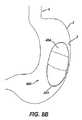
ある設定において、胃バンド(20)は、患者の胃食道接合部の周囲に適用される。具体的には、図2に示されるように、胃バンド(20)は、ブラダ(22)の外部上のストラップ(24)を使用して、ブラダ(22)が胃食道接合の組織に隣接するように取り付けられる。胃バンド(20)が患者の胃(2)の周りに巻き付けられると、ストラップ(24)の末端部は互いに対して固定される。この例ではストラップ(24)は可撓性であるが、ストラップ(24)は、その長さに沿った伸張を実質的に妨げる。したがって、(例えば、注入ポート(12)の隔膜(16)を貫通して挿入された針などを使用して)流体がブラダ(22)に加えられると、ブラダ(22)は膨張し、患者の胃食道接合部に内向きの力を加える。これにより、胃食道接合部の内部小孔のサイズが低減され、それによって患者の胃(2)の中への食物摂取量に制限部を加える。この小孔のサイズは、より大きな制限部の程度を作り出すためにブラダ(22)に更なる流体を加えることによって減少させることができ、又は制限部の程度を低減するためにブラダ(22)から流体を引き抜くことによって増加させることができることを理解すべきである。 In one setting, the gastric band (20) is applied around the patient's gastroesophageal junction. Specifically, as shown in FIG. 2, the gastric band (20) uses a strap (24) on the exterior of the bladder (22) so that the bladder (22) is adjacent to the gastroesophageal junction tissue. It is attached as follows. As the gastric band (20) is wrapped around the patient's stomach (2), the ends of the strap (24) are secured relative to each other. In this example, the strap (24) is flexible, but the strap (24) substantially prevents extension along its length. Thus, when fluid is added to the bladder (22) (eg, using a needle or the like inserted through the septum (16) of the injection port (12)), the bladder (22) expands and the patient's Apply inward force to the gastroesophageal junction. This reduces the size of the internal stoma of the gastroesophageal junction, thereby adding a restriction on food intake into the patient's stomach (2). This pore size can be reduced by adding additional fluid to the bladder (22) to create a greater degree of restriction or from the bladder (22) to reduce the degree of restriction. It should be understood that it can be increased by withdrawing fluid.
図2〜図4に示されるように、本例では、取り付けられた胃バンド(20)は、食道(4)との接合部付近の胃(2)の上部を少なくとも実質的に包囲する。図3は、収縮形状の胃バンド(20)を示しており、ブラダ(22)は流体をほとんど収容しておらず、それにより胃(2)に通じる小孔開口部のサイズは最大となっている。図4は、流体が充填されている膨張形状の胃バンド(20)を示しており、ブラダ(22)は、図3よりも実質的に多い流体を収容している。図4に示されるこの形状では、胃(2)に対する胃バンド(20)の圧力は、ブラダ(22)内の流体が増加したため増大し、それによって小孔開口部は小さくなり、食物摂取量制限部を形成する。図4は、患者の横隔膜筋(8)の下に上側嚢(6)を形成するための、胃バンド(20)の上方の食道(4)の拡張も概略的に示している。胃バンドシステム(10)が患者に埋め込まれ、初期量の流体(例えば、生理食塩水等)が胃バンドシステム(10)に導入された後、医師は、注入ポート(12)の隔膜(16)を通して挿入された針(例えば、ヒューバー針等)を使用して、胃バンドシステム(10)の中の流体量を時折調節する必要があり得る。例えば、そうした調節は、患者によって達成された体重減少を明らかにするために望ましくあり得、胃バンドシステム(10)が埋め込まれた後、1ヵ月前後(又は他の任意の好適な期間)で開始されてもよい。 As shown in FIGS. 2-4, in this example, the attached gastric band (20) at least substantially surrounds the upper portion of the stomach (2) near the junction with the esophagus (4). FIG. 3 shows a contracted gastric band (20) in which the bladder (22) contains little fluid, thereby maximizing the size of the stoma opening leading to the stomach (2). Yes. FIG. 4 shows an inflated gastric band (20) filled with fluid, where the bladder (22) contains substantially more fluid than FIG. In this configuration shown in FIG. 4, the pressure of the gastric band (20) against the stomach (2) increases due to increased fluid in the bladder (22), thereby reducing the stoma opening and limiting food intake. Forming part. FIG. 4 also schematically shows dilation of the esophagus (4) above the gastric band (20) to form an upper sac (6) under the patient's diaphragm muscle (8). After the gastric band system (10) is implanted in the patient and an initial amount of fluid (eg, saline, etc.) has been introduced into the gastric band system (10), the physician can use the diaphragm (16) of the infusion port (12). It may be necessary to occasionally adjust the amount of fluid in the gastric band system (10) using a needle (such as a Huber needle) inserted through. For example, such adjustment may be desirable to account for the weight loss achieved by the patient, starting around one month (or any other suitable period) after the gastric band system (10) is implanted. May be.
いくつかのシナリオにおいては、患者が摂食中の場合、図4に示される膨張状態までだけ胃バンド(20)を膨張させ、患者が空腹状態にあるか、又は別様に摂食中でない場合、図3に示される崩壊状態まで胃バンド(20)を戻すのが望ましくあり得る。したがって、ある設定では、患者が摂食中であるか否かに基づいて胃バンド(20)の状態を変化させるように構成されたポンプを設けるのが望ましくあり得る。図5A〜図5Bは、胃バンドシステム(10)に組み込まれるのが可能な代表的なヒドロゲルポンプ(100)を示す。具体的には、ヒドロゲルポンプ(100)は、胃バンドシステム(10)のカテーテル(18)に連結されるカテーテル(19)と流体連通してもよい。例えば、カテーテル(19)は、従来の「T」若しくは「Y」連結、又は他の任意の好適なやり方で、カテーテル(18)に結合されてもよい。あるいは、カテーテル(19)は、胃バンド(20)のブラダ(22)に直接連結されてもよく、注入ポート(12)に直接結合されてもよく、又は別のやり方で胃バンドシステム(10)に組み込まれてもよい。本例では、ヒドロゲルポンプ(100)は胃バンドシステム(10)と流体連通しているが、ヒドロゲルポンプ(100)及び胃バンドシステム(10)は、依然として、一緒になって、図1に示される胃バンドシステム(10)のような閉鎖流体回路を形成している。 In some scenarios, if the patient is eating, the gastric band (20) is inflated only to the inflated state shown in FIG. 4 and the patient is hungry or otherwise not eating It may be desirable to return the gastric band (20) to the collapsed state shown in FIG. Thus, in certain settings, it may be desirable to provide a pump configured to change the state of the gastric band (20) based on whether the patient is eating. 5A-5B show an exemplary hydrogel pump (100) that can be incorporated into the gastric band system (10). Specifically, the hydrogel pump (100) may be in fluid communication with a catheter (19) that is coupled to the catheter (18) of the gastric band system (10). For example, the catheter (19) may be coupled to the catheter (18) in a conventional “T” or “Y” connection, or any other suitable manner. Alternatively, the catheter (19) may be directly coupled to the bladder (22) of the gastric band (20), directly coupled to the infusion port (12), or otherwise the gastric band system (10). It may be incorporated into. In this example, the hydrogel pump (100) is in fluid communication with the gastric band system (10), but the hydrogel pump (100) and the gastric band system (10) are still shown together in FIG. It forms a closed fluid circuit like the gastric band system (10).
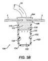
図のように、ヒドロゲルポンプ(100)は、患者の胃(2)の壁(3)に固定されたハウジング(102)を備えている。具体的には、ヒドロゲルポンプ(100)は、患者の胃(2)の内部の中に固定され、カテーテル(19)が患者の胃(2)から外部に伸張して胃バンドシステム(10)に連結する。単なる例として、ハウジング(102)は、患者の胃(2)の下部/遠心領域に固定されてもよいが、他の任意の好適な位置又は複数の位置が用いられてもよい。カテーテル(19)は、患者の胃(2)の壁(3)に形成された開口部を通って送り込まれ、一対のフランジ(104、106)が、壁(3)の対向する面に、この開口部に隣接して固定される。フランジ(104、106)は、カテーテル(19)に対して及び壁(3)の対向する面に対して密封し、そのため流体は、フランジ(104、106)とカテーテル(19)との間の境界面を通って漏出できず、また流体は、フランジ(104、106)と壁(3)との間の境界面を通って漏出できない。換言すれば、本例では、カテーテル(19)の内部ルーメンだけが、壁(3)を通した流体連通のための経路である。フランジ(104、106)は、1種又は2種以上のバイオ外科手術用接着剤(例えば、シアノアクリレート、イソシアネート等)を使用して及び/又は他の任意の好適な装置、物質、又は技術を用いて壁(3)に封止されてもよい。フランジ(104、106)はまた、任意の好適な方法でカテーテル(19)に封止されてもよい。フランジ(106)は、ハウジング(102)の蓋を形成してもよく、フランジ(106)はハウジング(102)にも封止される。 As shown, the hydrogel pump (100) comprises a housing (102) secured to the wall (3) of the patient's stomach (2). Specifically, the hydrogel pump (100) is secured within the patient's stomach (2) and the catheter (19) extends out of the patient's stomach (2) and into the gastric band system (10). Link. Merely by way of example, the housing (102) may be secured to the lower / centrifugal region of the patient's stomach (2), although any other suitable location or locations may be used. The catheter (19) is fed through an opening formed in the wall (3) of the patient's stomach (2), and a pair of flanges (104, 106) are placed on the opposing surfaces of the wall (3) on this side. It is fixed adjacent to the opening. The flange (104, 106) seals against the catheter (19) and against the opposing surface of the wall (3) so that fluid is bounded between the flange (104, 106) and the catheter (19). No fluid can leak through the surface and no fluid can leak through the interface between the flange (104, 106) and the wall (3). In other words, in this example, only the internal lumen of the catheter (19) is the path for fluid communication through the wall (3). The flanges (104, 106) may use one or more biosurgical adhesives (eg, cyanoacrylates, isocyanates, etc.) and / or any other suitable device, material, or technique. It may be used and sealed to the wall (3). The flanges (104, 106) may also be sealed to the catheter (19) in any suitable manner. The flange (106) may form a lid for the housing (102), and the flange (106) is also sealed to the housing (102).
本例のハウジング(102)は、胃(2)の中の酸性液及びその他の流体、胃運動性の粉砕及び撹拌機構、及び消化酵素による酵素の攻撃に実質的に耐え得る、実質的に硬質材料で形成される。例えば、ハウジング(102)は、生体適合性プラスチック、金属、又は他の任意の好適な材料若しくは材料の組み合わせで形成されてもよい。ハウジング(102)は、上方領域(110)と下方領域(120)とを含む。図5A〜図5Bにおいてハウジング(102)は断面で示されているが、ハウジング(102)は、円筒状などであるがこれに限定されない任意の好適形状を有することができることを理解すべきである。本例では、上方領域(110)及び下方領域(120)はピストンディスク(130)によって分離される。生理食塩水などの流体(112)は上方領域(110)に提供され、カテーテル(19)を介して胃バンドシステム(10)と流体連通する。本例では、図5Aにおいて下よりの位置にあるピストンディスク(130)により、上方領域(110)は約2 ccの流体容量を有する。あるいは、上方領域(110)は、その他の任意の好適な流体容量を有してもよい。 The housing (102) of this example is substantially rigid that can substantially withstand the attack of the enzyme by acidic fluids and other fluids in the stomach (2), gastric motility crushing and agitation mechanisms, and digestive enzymes. Formed of material. For example, the housing (102) may be formed of a biocompatible plastic, metal, or any other suitable material or combination of materials. The housing (102) includes an upper region (110) and a lower region (120). Although the housing (102) is shown in cross section in FIGS. 5A-5B, it should be understood that the housing (102) can have any suitable shape, such as but not limited to a cylindrical shape. . In this example, the upper region (110) and the lower region (120) are separated by a piston disk (130). Fluid (112), such as saline, is provided to the upper region (110) and is in fluid communication with the gastric band system (10) via the catheter (19). In this example, the upper region (110) has a fluid capacity of about 2 cc with the piston disk (130) in the lower position in FIG. 5A. Alternatively, the upper region (110) may have any other suitable fluid capacity.
環境感受性ヒドロゲル(122)は、ハウジング(120)の下方領域(120)に提供される。ピストンディスク(130)は、ハウジング(102)の内壁(132)に対して実質的に密封し、その結果ピストンディスク(130)は上方領域(110)を下方領域(120)から流体的に分離する。以下により詳細に記載されるように、ピストンディスク(130)は、流体(112)を上方領域(110)から放出するために、ハウジング(102)によって画定される長手方向軸に沿って移動可能である。ハウジング(110)内でのかかる移動中及び移動後でさえも、ピストンディスク(130)は、上方領域(110)と下方領域(120)との間の封止を維持する。周縁(134)は、ハウジングの内壁(132)から半径方向内向きに突出して、ピストンディスク(130)の外径よりも小さな内径を提供する。したがって、周縁(134)は、ピストンディスク(130)の降下を制限し、それによりピストンディスク(130)は、図5Aに示される位置よりも下には移動することができない。言うまでもなく、本明細書に記載される他の特徴部と同様に、周縁(134)は単に任意の部材である。 An environmentally sensitive hydrogel (122) is provided in the lower region (120) of the housing (120). The piston disk (130) substantially seals against the inner wall (132) of the housing (102) so that the piston disk (130) fluidly separates the upper region (110) from the lower region (120). . As described in more detail below, the piston disk (130) is movable along a longitudinal axis defined by the housing (102) to release fluid (112) from the upper region (110). is there. During and after such movement in the housing (110), the piston disk (130) maintains a seal between the upper region (110) and the lower region (120). The peripheral edge (134) projects radially inward from the inner wall (132) of the housing to provide an inner diameter that is smaller than the outer diameter of the piston disk (130). Thus, the peripheral edge (134) limits the lowering of the piston disk (130) so that the piston disk (130) cannot move below the position shown in FIG. 5A. Of course, like the other features described herein, the perimeter (134) is simply an optional member.
ハウジング(102)の下方領域(120)は、その中に形成される複数の開口部(124)を有し、それにより胃液がハウジング(102)の下方領域(120)に自由に出入りすることができ、胃(2)の中で生じている生理学的状態の変化(例えば、摂取及び空腹時に関連する)を、ハウジング(102)の内部下方領域(120)でも生じさせることができる。したがって、本例では、ヒドロゲル(122)は、開口部(124)を介して胃(2)の内部と流体連通する。更に、本例のヒドロゲル(122)は、低いpH環境では崩壊状態にあり(図5A)、pH値の上昇に応答して膨潤及び膨張する(図5B)ように調製及び構成される。pHの上昇は患者が食物を摂取し始めると生じる場合があり、患者が空腹時ないしは別様に食物を摂取していないときに、胃(2)の中のpH値は下がる場合があることを、当業者は理解されよう。単なる例として、ヒドロゲル(122)は、およそ4以上(又はおよそ5以上)のpH値に暴露されると膨張状態(図5B)へと膨潤し、およそ4未満(又はおよそ5未満)のpH値に暴露されると崩壊状態(図5A)となるように、調製及び構成されてもよい。あるいは、ヒドロゲル(122)は、他の任意の好適なpH値に応答して膨潤又は収縮(shrink)するように調製及び構成されてもよい。本例においてヒドロゲル(122)が膨潤すると、ピストンディスク(130)は、図5Bに示されるように上方に押し上げられることとなり、このことが更にまた流体(112)を、ハウジングの上方領域(110)から胃バンドシステム(10)に押し出す。開口部(124)は、膨潤したヒドロゲル(122)が、開口部(124)を通って突出するのではなく、ピストンディスク(130)を上方に押し上げるのに好都合であるように、寸法設定及び構成される。ヒドロゲル(122)はこうして、患者の胃(2)の中の流体のpH値に基づいて、ピストンディスク(130)を駆動する。特定のヒドロゲル調製物及び構成は、膨潤したヒドロゲル(122)がピストンディスク(130)に加える圧力(図5B)が、胃バンドシステム(10)に対して望ましい流体(112)の圧力を提供するように選択され得る。 The lower region (120) of the housing (102) has a plurality of openings (124) formed therein so that gastric fluid can freely enter and exit the lower region (120) of the housing (102). The changes in physiological conditions occurring in the stomach (2) (eg, related to ingestion and fasting) can also occur in the interior lower region (120) of the housing (102). Thus, in this example, the hydrogel (122) is in fluid communication with the interior of the stomach (2) via the opening (124). Furthermore, the hydrogel (122) of the present example is prepared and configured to be in a collapsed state in a low pH environment (FIG. 5A) and swell and expand in response to an increase in pH value (FIG. 5B). The increase in pH may occur when the patient begins to eat food, and the pH value in the stomach (2) may decrease when the patient is fasting or otherwise not eating food. Those skilled in the art will appreciate. By way of example only, hydrogel (122) swells to an expanded state (FIG. 5B) when exposed to a pH value of about 4 or higher (or about 5 or higher), and has a pH value of less than about 4 (or less than about 5). May be prepared and configured to be in a collapsed state (FIG. 5A) when exposed to. Alternatively, the hydrogel (122) may be prepared and configured to swell or shrink in response to any other suitable pH value. As the hydrogel (122) swells in this example, the piston disk (130) will be pushed upward as shown in FIG. 5B, which also causes the fluid (112) to flow into the upper region (110) of the housing. And extrude into the gastric band system (10). The opening (124) is sized and configured so that the swollen hydrogel (122) is convenient for pushing the piston disk (130) upward rather than protruding through the opening (124). Is done. The hydrogel (122) thus drives the piston disk (130) based on the pH value of the fluid in the patient's stomach (2). Certain hydrogel preparations and configurations are such that the pressure that the swollen hydrogel (122) applies to the piston disk (130) (FIG. 5B) provides the desired fluid (112) pressure to the gastric band system (10). Can be selected.
以上に鑑みて、患者が食物を摂取し始める前、ヒドロゲル(122)は図5Aに示されるような崩壊状態にあり得ることを理解すべきである。この時、胃バンド(20)もまた、図3に示される崩壊状態にあり得る。患者が食物を摂取し始めると、患者の胃(2)の中のpH値は上昇し始める。胃(2)の中の流体が開口部(124)を介して下方領域(120)の中に漏れるので、このpHの上昇はヒドロゲル(122)によって検知される。このpHの上昇に応答して、ヒドロゲル(122)は、図5Bに示される膨張状態へと膨潤する。この膨潤はピストンディスク(130)を上昇位置まで駆動し、それによって流体(112)を、ハウジングの上方領域(110)から胃バンドシステム(10)へと押し出す。次に、胃バンド(20)は図4に示される膨張状態に達して、患者の胃食道接合部に制限部を作り出す。患者が摂食を終了した後、患者の生理機能は、最終的に空腹時の段階に戻り、患者の胃の中のpH値は低下する。このpH値の低下により、ヒドロゲル(122)は図5Aに示される形状まで崩壊して戻る。加えて、胃バンドシステム(10)の中の流体(112)の圧力は、ピストンディスク(130)を図5Aに示される位置まで戻し、それにより、流体(112)は胃バンドシステム(10)からハウジング(120)の上方領域(110)の中に排出され、胃バンド(20)は図3に示される崩壊状態に戻る。言うまでもなく、ヒドロゲルポンプ(100)の様々な特徴及び構成要素は、全て省略できないにしても、種々の方法で変更、置き換え、又は補足されてもよい。ヒドロゲルポンプ(100)の多くの好適な変形は、本明細書の教示を考慮すれば当業者には明らかであろう。 In view of the above, it should be understood that the hydrogel (122) may be in a collapsed state as shown in FIG. 5A before the patient begins to take food. At this time, the gastric band (20) may also be in the collapsed state shown in FIG. As the patient begins to eat food, the pH value in the patient's stomach (2) begins to rise. This increase in pH is detected by the hydrogel (122) as fluid in the stomach (2) leaks through the opening (124) into the lower region (120). In response to this pH increase, the hydrogel (122) swells to the expanded state shown in FIG. 5B. This swelling drives the piston disk (130) to the raised position, thereby pushing the fluid (112) from the upper region (110) of the housing to the gastric band system (10). The gastric band (20) then reaches the expanded state shown in FIG. 4 to create a restriction at the patient's gastroesophageal junction. After the patient has finished eating, the patient's physiology eventually returns to the fasting stage and the pH value in the patient's stomach decreases. This decrease in pH value causes the hydrogel (122) to collapse back to the shape shown in FIG. 5A. In addition, the pressure of the fluid (112) in the gastric band system (10) returns the piston disk (130) to the position shown in FIG. 5A so that the fluid (112) is removed from the gastric band system (10). The gastric band (20) returns to the collapsed state shown in FIG. 3 as it is expelled into the upper region (110) of the housing (120). Of course, the various features and components of the hydrogel pump (100) may not be omitted, but may be altered, replaced, or supplemented in various ways. Many suitable variations of the hydrogel pump (100) will be apparent to those skilled in the art in view of the teachings herein.
ヒドロゲルポンプ(100)の単なる例示的変形では、pH値に対するヒドロゲル(122)の応答性は逆にされる。具体的には、ヒドロゲル(122)は、低いpH値に応答して膨張し(図5A)、高いpH値に応答して崩壊する(図5B)ように構成される。こうした逆の応答は、胃バンド(20)が、(例えば、病的肥満を治療するために使用するのではなく)胃食道逆流性疾患(GERD)又は他の何らかの疾患を治療するために使用されるシナリオにおいて好適であり得る。いくつかのそのような変更形態では、ポンプ(100)は、患者の食道(4)に近接して、又は望ましくない胃酸の逆流の発生に対する応答を提供することができる何らかの他の好適な位置に設置されてもよい。望ましくない胃酸の逆流の発生に応答してバンド(20)を締め付けることにより、こうした胃酸の逆流に起因した損傷の可能性を低減することができる。 In merely an exemplary variation of the hydrogel pump (100), the responsiveness of the hydrogel (122) to the pH value is reversed. Specifically, the hydrogel (122) is configured to swell in response to a low pH value (FIG. 5A) and to disintegrate in response to a high pH value (FIG. 5B). Such an inverse response is used by gastric band (20) to treat gastroesophageal reflux disease (GERD) or any other disease (eg, not to treat morbid obesity). In certain scenarios. In some such variations, the pump (100) is in close proximity to the patient's esophagus (4) or in some other suitable location that can provide a response to the occurrence of undesirable gastric acid reflux. It may be installed. By tightening the band (20) in response to the occurrence of undesirable gastric acid reflux, the potential for damage due to such gastric acid reflux can be reduced.
ヒドロゲルポンプ(100)の別の単なる例示的変形として、ヒドロゲルポンプ(100)は胃バルブに連結されて、バルブを実質的な制限構造と実質的な非制限構造との間で駆動してもよい。例えば、ヒドロゲルポンプ(100)は、その開示が参照により本明細書に組み込まれる米国出願公開第2006/0235448号、発明の名称「Artificial Gastric Valve」(2006年10月19日公開)に記載のように、胃バルブに連結されてもよい。ヒドロゲルポンプ(100)をそのような胃バルブに連結することができる種々の好適な方法は、本明細書の教示を考慮すれば当業者には明らかであろう。ヒドロゲルポンプ(100)(又はその変形)を使用することができる更に他の好適な方法もまた、本明細書の教示を考慮すれば当業者には明らかであろう。 As another merely exemplary variation of hydrogel pump (100), hydrogel pump (100) may be coupled to a gastric valve to drive the valve between a substantially restrictive structure and a substantially unrestricted structure. . For example, the hydrogel pump (100) is as described in US Application Publication No. 2006/0235448, entitled “Artificial Gastric Valve” (published Oct. 19, 2006), the disclosure of which is incorporated herein by reference. In addition, it may be connected to a gastric valve. Various suitable ways in which the hydrogel pump (100) can be coupled to such a gastric valve will be apparent to those skilled in the art in view of the teachings herein. Still other suitable methods in which the hydrogel pump (100) (or variations thereof) can be used will also be apparent to those skilled in the art in view of the teachings herein.
胃バンドを作動させるためのヒドロゲル流体リザーバの収縮
図6A〜図6Bは、胃バンドシステム(10)に組み込まれることができる例示的なヒドロゲル流体リザーバ(200)を示す。したがって、ヒドロゲル流体リザーバ(200)は、上述のヒドロゲルポンプ(100)に代わるものとして使用され得る。具体的には、ヒドロゲル流体リザーバ(200)は、胃バンドシステム(10)のカテーテル(18)に連結されたカテーテル(19)と流体連通してもよい。例えば、カテーテル(19)は、従来の「T」若しくは「Y」連結、又は他の任意の好適なやり方で、カテーテル(18)に結合されてもよい。あるいは、カテーテル(19)は、胃バンド(20)のブラダ(22)に直接連結されてもよく、注入ポート(12)に直接結合されてもよく、又は別のやり方で胃バンドシステム(10)に組み込まれてもよい。本例では、ヒドロゲル流体リザーバ(200)は胃バンドシステム(10)と流体連通するが、ヒドロゲル流体リザーバ(200)及び胃バンドシステム(10)は、依然として、一緒になって、図1に示される胃バンドシステム(10)のような閉鎖流体回路を形成している。Contraction of Hydrogel Fluid Reservoir to Activate Gastric Band FIGS. 6A-6B illustrate an exemplary hydrogel fluid reservoir (200) that can be incorporated into the gastric band system (10). Thus, the hydrogel fluid reservoir (200) can be used as an alternative to the hydrogel pump (100) described above. Specifically, the hydrogel fluid reservoir (200) may be in fluid communication with a catheter (19) coupled to the catheter (18) of the gastric band system (10). For example, the catheter (19) may be coupled to the catheter (18) in a conventional “T” or “Y” connection, or any other suitable manner. Alternatively, the catheter (19) may be directly coupled to the bladder (22) of the gastric band (20), directly coupled to the infusion port (12), or otherwise the gastric band system (10). It may be incorporated into. In this example, the hydrogel fluid reservoir (200) is in fluid communication with the gastric band system (10), but the hydrogel fluid reservoir (200) and the gastric band system (10) are still shown together in FIG. It forms a closed fluid circuit like the gastric band system (10).
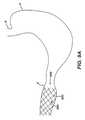
図のように、ヒドロゲル流体リザーバ(200)は、ヒドロゲル(202)から形成される中空の球体を備えている。この例では、ヒドロゲル(202)は、球体として形成されているが、他の任意の好適な形状を用いることもできることを理解すべきである。ヒドロゲル球体(202)は、患者の胃(2)の壁(3)に固定される。具体的には、ヒドロゲル球体(202)は、患者の胃(2)の内部の中に固定され、カテーテル(19)が患者の胃(2)から外部に伸張して胃バンドシステム(10)に連結する。単なる例として、球体(202)は、患者の胃(2)の下部/遠心領域に固定されてもよいが、他の任意の好適な位置又は複数の位置が用いられてもよい。カテーテル(19)は、患者の胃(2)の壁(3)に形成された開口部を通って送り込まれ、一対のフランジ(104、106)が、壁(3)の対向する面に、この開口部に隣接して固定される。フランジ(104、106)は、ヒドロゲルポンプ(100)に関して前述したものと同様に構成されてもよく、又は他の任意の好適な構成を有してもよい。本例では、カテーテル(19)の内部ルーメンだけが、壁(3)を通した流体連通のための経路である。ヒドロゲル球体(202)は中空内部(204)つまりリザーバを画定し、内部に流体(212)(例えば、生理食塩水等)が存在する。中空内部(204)及び流体(212)はカテーテル(19)と連通し、それにより、以下により詳細に記載されるようにヒドロゲル球体(202)が崩壊すると、流体(212)はカテーテル(19)を介して胃バンド(20)に向けて押し出され得る。 As shown, the hydrogel fluid reservoir (200) comprises a hollow sphere formed from the hydrogel (202). In this example, the hydrogel (202) is formed as a sphere, but it should be understood that any other suitable shape may be used. The hydrogel sphere (202) is secured to the wall (3) of the patient's stomach (2). Specifically, the hydrogel sphere (202) is secured within the patient's stomach (2) and the catheter (19) extends out of the patient's stomach (2) into the gastric band system (10). Link. Merely by way of example, the sphere (202) may be secured to the lower / centrifugal region of the patient's stomach (2), although any other suitable location or locations may be used. The catheter (19) is fed through an opening formed in the wall (3) of the patient's stomach (2), and a pair of flanges (104, 106) are placed on the opposing surfaces of the wall (3) on this side. It is fixed adjacent to the opening. The flanges (104, 106) may be configured similar to that described above with respect to the hydrogel pump (100), or may have any other suitable configuration. In this example, only the internal lumen of the catheter (19) is the path for fluid communication through the wall (3). The hydrogel sphere (202) defines a hollow interior (204) or reservoir in which a fluid (212) (eg, saline, etc.) is present. The hollow interior (204) and fluid (212) communicate with the catheter (19) so that when the hydrogel sphere (202) collapses as described in more detail below, the fluid (212) causes the catheter (19) to move. Through the gastric band (20).
本例では、ヒドロゲル球体(202)は、全体がヒドロゲルで形成される。いくつかのその他の変更形態では、中空内部(204)は、例えば流体(212)をヒドロゲル(202)から流体的に分離するために、中空内部(204)はシリコーン又は何らかの他の材料(図示せず)で裏打ちされる。これに加えて又は代替として、ヒドロゲル球体(202)の外面の周りにジャケット又はケース(図示せず)が設けられてもよい。そのようなジャケット又はケースは多孔質であってもよく、その中に形成された開口部を有していてもよく、ないしは別の方法で胃(2)の中の流体がヒドロゲル(202)と接触できるようしてもよい。ヒドロゲル球体(202)の内部及び/又は外部にそのような構成要素を設けることによって、ヒドロゲル球体(202)の構造的一体性を高めることができ、尚且つ、以下により詳細に記載されるようにヒドロゲル球体(202)が膨張又は収縮するのを可能とする。更に、いくつかの変形では、ヒドロゲル球体(202)の外面に設けられたジャケットは、多孔質であるのに加えて、実質的に弾性である。例えば、そのような弾性ジャケットは、図6Bに示されているものと同様に、収縮位置に弾性的に付勢され得る。いくつかのそのような変更形態では、ヒドロゲル球体(202)が図6Aに示される膨張した形状であるとき、弾性ジャケットはその付勢に逆らって伸張し、ジャケットの弾性付勢は、ヒドロゲル球体(202)が図6Bに示される崩壊した形状に達するのを補助する。あるいは、弾性ジャケットは、ヒドロゲル球体(202)が崩壊した形状に達するのを必ずしも補助せずに、ヒドロゲル球体(202)と共に図6Bに示される崩壊した形状へと単に移動してもよい。例えば、ヒドロゲル球体(202)の上又は内部に設けることができるその他の構成要素などであるが、これらに限定されない、ヒドロゲル球体(202)を構成することができる他の種々の代替的方法は、本明細書の教示を考慮すれば当業者には明らかであろう。同様に、カテーテル(19)をヒドロゲル球体(202)に連結することができる様々な方法は、本明細書の教示を考慮すれば当業者には明らかであろう。 In this example, the hydrogel sphere (202) is formed entirely of hydrogel. In some other variations, the hollow interior (204) may be silicone or some other material (not shown), eg, to fluidly separate the fluid (212) from the hydrogel (202). Z)). In addition or alternatively, a jacket or case (not shown) may be provided around the outer surface of the hydrogel sphere (202). Such a jacket or case may be porous and may have an opening formed therein, or otherwise the fluid in the stomach (2) and the hydrogel (202). It may be possible to make contact. By providing such components inside and / or outside of the hydrogel sphere (202), the structural integrity of the hydrogel sphere (202) can be increased and as described in more detail below. Allow the hydrogel sphere (202) to expand or contract. Further, in some variations, the jacket provided on the outer surface of the hydrogel sphere (202) is substantially elastic in addition to being porous. For example, such an elastic jacket can be elastically biased to a retracted position, similar to that shown in FIG. 6B. In some such variations, when the hydrogel sphere (202) is in the expanded configuration shown in FIG. 6A, the elastic jacket stretches against its bias, and the elastic bias of the jacket causes the hydrogel sphere ( 202) helps to reach the collapsed shape shown in FIG. 6B. Alternatively, the elastic jacket may simply move with the hydrogel sphere (202) to the collapsed shape shown in FIG. 6B without necessarily assisting the hydrogel sphere (202) to reach the collapsed shape. Various other alternative ways in which the hydrogel sphere (202) can be constructed, such as but not limited to other components that can be provided on or in the hydrogel sphere (202) include: It will be apparent to those skilled in the art from consideration of the teachings herein. Similarly, the various ways in which the catheter (19) can be coupled to the hydrogel sphere (202) will be apparent to those skilled in the art in view of the teachings herein.
本例においてヒドロゲル球体(202)を形成するヒドロゲルは、ヒドロゲル球体(202)が膨潤状態(図6A)と崩壊状態(図6B)との間で変化するように、環境感受性である。具体的には、ヒドロゲル球体(202)のヒドロゲルは、低いpH環境では膨張状態であり(図6A)、pH値の上昇に応答して崩壊する(図6B)ように、調製及び構成される。pHの上昇は患者が食物を摂取し始めると生じる場合があり、患者が空腹時ないしは別様に食物を摂取していないときに、胃(2)の中のpH値は下がる場合があることを、当業者は理解されよう。単なる例として、ヒドロゲル球体(202)は、およそ4以上(又はおよそ5以上)のpH値に暴露されると崩壊状態に収縮し(図6B)、およそ4未満(又はおよそ5未満)のpH値に暴露されると膨張状態へと膨潤する(図6A)ように、調製及び構成されてもよい。あるいは、ヒドロゲル球体(202)は、他の任意の好適なpH値に応答して膨潤又は収縮するように調製及び構成されてもよい。 The hydrogel that forms the hydrogel spheres (202) in this example is environmentally sensitive such that the hydrogel spheres (202) change between a swollen state (FIG. 6A) and a collapsed state (FIG. 6B). Specifically, the hydrogel of the hydrogel sphere (202) is prepared and configured so that it is in an expanded state in a low pH environment (FIG. 6A) and disintegrates in response to an increase in pH value (FIG. 6B). The increase in pH may occur when the patient begins to eat food, and the pH value in the stomach (2) may decrease when the patient is fasting or otherwise not eating food. Those skilled in the art will appreciate. By way of example only, the hydrogel sphere (202) contracts into a collapsed state when exposed to a pH value of about 4 or higher (or about 5 or higher) (FIG. 6B), with a pH value of less than about 4 (or less than about 5). May be prepared and configured to swell into an expanded state when exposed to (FIG. 6A). Alternatively, the hydrogel sphere (202) may be prepared and configured to swell or shrink in response to any other suitable pH value.
ヒドロゲル球体(202)が図6Aに示されるような膨張状態にある場合、その中空内部(204)は、およそ2 ccの容量を有するリザーバを提供する。あるいは、膨張したヒドロゲル球体(202)の中空内部(204)は、他の任意の好適な容量を有してもよい。ヒドロゲル球体(202)が図6Bに示されるような崩壊状態に収縮すると、中空内部(204)によってもたらされるリザーバの容量は低減することとなり、このことが更にまた流体(212)を、中空内部(204)から胃バンドシステム(10)に押し出す。こうして、ヒドロゲル球体(202)は、患者の胃(2)の中の流体のpH値に基づいて、流体(212)を中空内部(204)から胃バンドシステム(10)へと駆動する。特定のヒドロゲル調製物及び構成は、収縮するヒドロゲル球体(202)が流体(212)に加える圧力(図6B)が、胃バンドシステム(10)に対して望ましい流体(112)の圧力を提供するように選択され得る。 When the hydrogel sphere (202) is in an expanded state as shown in FIG. 6A, its hollow interior (204) provides a reservoir with a capacity of approximately 2 cc. Alternatively, the hollow interior (204) of the expanded hydrogel sphere (202) may have any other suitable volume. When the hydrogel sphere (202) contracts to the collapsed state as shown in FIG. 6B, the volume of the reservoir provided by the hollow interior (204) will be reduced, which also causes the fluid (212) to flow into the hollow interior ( 204) to the gastric band system (10). Thus, the hydrogel sphere (202) drives the fluid (212) from the hollow interior (204) to the gastric band system (10) based on the pH value of the fluid in the patient's stomach (2). Certain hydrogel preparations and configurations are such that the pressure (FIG. 6B) that the shrinking hydrogel sphere (202) exerts on the fluid (212) provides the desired fluid (112) pressure to the gastric band system (10). Can be selected.
以上に鑑みて、患者が食物を摂取し始める前、ヒドロゲル球体(202)は、図6Aに示されるような膨張状態にあり得ることを理解すべきである。この時、胃バンド(20)もまた、図3に示される崩壊状態にあり得る。患者が食物を摂取し始めると、患者の胃(2)の中のpH値は上昇し始める。胃(2)の中の流体がヒドロゲル球体(202)と連通しているので、このpHの上昇はヒドロゲル球体(202)によって検知される。このpHの上昇に応答して、ヒドロゲル球体(202)は、図6に示される崩壊状態へと収縮する。この収縮は中空内部(204)の容量を低減し、それによって流体(212)を、ヒドロゲル球体(202)から胃バンドシステム(10)へと押し出す。次に、胃バンド(20)は図4に示される膨張状態に達して、患者の胃食道接合部に制限部を形成する。患者が摂食を終了した後、患者の生理機能は、最終的に空腹時の段階に戻り、患者の胃の中のpH値は低下する。このpH値の低下により、ヒドロゲル球体(202)は図6Aに示される膨張した形状まで膨潤して戻ることとなり、このことが更にまた、中空内部(204)によってもたらされるリザーバの容量を増加させる。加えて、胃バンドシステム(10)の中の流体(212)の圧力は、流体(212)を中空内部(204)に戻し、それにより、流体(212)は胃バンドシステム(10)から中空内部(204)の中に排出され、胃バンド(20)は図3の崩壊状態に戻る。言うまでもなく、ヒドロゲルリザーバ(200)の様々な特徴及び構成要素は、全て省略できないにしても、種々の方法で変更、置き換え、又は補足されてもよい。ヒドロゲルリザーバ(200)の多くの好適な変形は、本明細書の教示を考慮すれば当業者には明らかであろう。 In view of the above, it should be understood that the hydrogel sphere (202) may be in an expanded state as shown in FIG. 6A before the patient begins to take food. At this time, the gastric band (20) may also be in the collapsed state shown in FIG. As the patient begins to eat food, the pH value in the patient's stomach (2) begins to rise. This increase in pH is detected by the hydrogel sphere (202) because the fluid in the stomach (2) is in communication with the hydrogel sphere (202). In response to this pH increase, the hydrogel sphere (202) contracts to the collapsed state shown in FIG. This contraction reduces the volume of the hollow interior (204), thereby pushing fluid (212) from the hydrogel sphere (202) to the gastric band system (10). The gastric band (20) then reaches the expanded state shown in FIG. 4 to form a restriction at the patient's gastroesophageal junction. After the patient has finished eating, the patient's physiology eventually returns to the fasting stage and the pH value in the patient's stomach decreases. This drop in pH value causes the hydrogel sphere (202) to swell back to the expanded shape shown in FIG. 6A, which again increases the reservoir capacity provided by the hollow interior (204). In addition, the pressure of the fluid (212) in the gastric band system (10) returns the fluid (212) to the hollow interior (204) so that the fluid (212) is removed from the gastric band system (10). (204) and the gastric band (20) returns to the collapsed state of FIG. Of course, the various features and components of the hydrogel reservoir (200) may not be omitted, but may be altered, replaced, or supplemented in various ways. Many suitable variations of the hydrogel reservoir (200) will be apparent to those skilled in the art in view of the teachings herein.
ヒドロゲルリザーバ(200)の単なる例示的変形では、pH値に対するヒドロゲル球体(202)の応答性は逆にされる。具体的には、ヒドロゲル球体(202)は、低いpH値に応答して崩壊し(図6B)、高いpH値に応答して膨潤する(図6A)ように構成される。こうした逆の応答は、胃バンド(20)が、(例えば、病的肥満を治療するために使用するのではなく)胃食道逆流性疾患(GERD)又は他の何らかの疾患を治療するために使用されるシナリオにおいて好適であり得る。いくつかのそのような変更形態では、リザーバ(200)は、患者の食道(4)に近接して、又は望ましくない胃酸の逆流の発生に対する応答を提供することができる何らかの他の好適な位置に設置されてもよい。望ましくない胃酸の逆流の発生に応答してバンド(20)を締め付けることにより、こうした胃酸の逆流に起因した損傷の可能性を低減することができる。ヒドロゲルリザーバ(200)(又はその変形)を使用することができる更に他の好適な方法もまた、本明細書の教示を考慮すれば当業者には明らかであろう。 In an exemplary variation of the hydrogel reservoir (200), the responsiveness of the hydrogel sphere (202) to pH values is reversed. Specifically, the hydrogel sphere (202) is configured to collapse in response to a low pH value (FIG. 6B) and swell in response to a high pH value (FIG. 6A). Such an inverse response is used by gastric band (20) to treat gastroesophageal reflux disease (GERD) or any other disease (eg, not to treat morbid obesity). In certain scenarios. In some such variations, the reservoir (200) is in proximity to the patient's esophagus (4) or in some other suitable location that can provide a response to the occurrence of undesirable gastric acid reflux. It may be installed. By tightening the band (20) in response to the occurrence of undesirable gastric acid reflux, the potential for damage due to such gastric acid reflux can be reduced. Still other suitable methods in which the hydrogel reservoir (200) (or variations thereof) can be used will also be apparent to those skilled in the art in view of the teachings herein.
胃バンドを作動させるための流体リザーバの中のヒドロゲルの膨潤
図7A〜図7Bは、胃バンドシステム(10)に組み込まれることができる例示的なヒドロゲル流体リザーバ(300)を示す。したがって、ヒドロゲル流体リザーバ(300)は、上述のヒドロゲルポンプ(100)及びヒドロゲル流体リザーバ(200)に代わるものとして使用されることができる。具体的には、ヒドロゲル流体リザーバ(300)は、胃バンドシステム(10)のカテーテル(18)に連結されたカテーテル(19)と流体連通してもよい。例えば、カテーテル(19)は、従来の「T」若しくは「Y」連結、又は他の任意の好適なやり方で、カテーテル(18)に結合されてもよい。あるいは、カテーテル(19)は、胃バンド(20)のブラダ(22)に直接連結されてもよく、注入ポート(12)に直接結合されてもよく、又は別のやり方で胃バンドシステム(10)に組み込まれてもよい。本例では、ヒドロゲル流体リザーバ(300)は胃バンドシステム(10)と流体連通するが、ヒドロゲル流体リザーバ(300)及び胃バンドシステム(10)は、依然として、一緒になって、図1に示される胃バンドシステム(10)のような閉鎖流体回路を形成している。Swelling of the hydrogel in the fluid reservoir to actuate the gastric band FIGS. 7A-7B illustrate an exemplary hydrogel fluid reservoir (300) that can be incorporated into the gastric band system (10). Thus, the hydrogel fluid reservoir (300) can be used as an alternative to the hydrogel pump (100) and hydrogel fluid reservoir (200) described above. Specifically, the hydrogel fluid reservoir (300) may be in fluid communication with a catheter (19) coupled to the catheter (18) of the gastric band system (10). For example, the catheter (19) may be coupled to the catheter (18) in a conventional “T” or “Y” connection, or any other suitable manner. Alternatively, the catheter (19) may be directly coupled to the bladder (22) of the gastric band (20), directly coupled to the infusion port (12), or otherwise the gastric band system (10). It may be incorporated into. In this example, the hydrogel fluid reservoir (300) is in fluid communication with the gastric band system (10), but the hydrogel fluid reservoir (300) and the gastric band system (10) are still shown together in FIG. It forms a closed fluid circuit like the gastric band system (10).
図のように、ヒドロゲル流体リザーバ(300)は、ヒドロゲル(304)で形成される中空の球体を被覆する外側ジャケット(302)を備えている。この例では、ヒドロゲル流体リザーバ(300)は、球体として形成されているが、他の任意の好適な形状を用いることもできることを理解すべきである。ヒドロゲル流体リザーバ(300)は、患者の胃(2)の壁(3)に固定される。具体的には、ヒドロゲル流体リザーバ(300)は、患者の胃(2)の内部の中に固定され、カテーテル(19)が患者の胃(2)から外部に伸張して胃バンドシステム(10)に連結する。単なる例として、ヒドロゲル流体リザーバ(300)は、患者の胃(2)の下部/遠心領域に固定されてもよいが、他の任意の好適な位置又は複数の位置が用いられてもよい。カテーテル(19)は、患者の胃(2)の壁(3)に形成された開口部を通って送り込まれ、一対のフランジ(104、106)が、壁(3)の対向する面に、この開口部に隣接して固定される。フランジ(104、106)は、ヒドロゲルポンプ(100)に関して前述したものと同様に構成されてもよく、又は他の任意の好適な構成を有してもよい。本例では、カテーテル(19)の内部ルーメンだけが、壁(3)を通した流体連通のための経路である。ヒドロゲル球体(304)は中空内部(306)つまりリザーバを画定し、内部に流体(312)(例えば、生理食塩水等)が存在する。中空内部(306)及び流体(312)はカテーテル(19)と連通し、それにより、以下により詳細に記載されるようにヒドロゲル球体(302)を形成するヒドロゲルが膨張すると、流体(312)はカテーテル(19)を介して胃バンド(20)に向けて押し出されることができる。 As shown, the hydrogel fluid reservoir (300) includes an outer jacket (302) covering a hollow sphere formed of hydrogel (304). In this example, the hydrogel fluid reservoir (300) is formed as a sphere, but it should be understood that any other suitable shape may be used. The hydrogel fluid reservoir (300) is secured to the wall (3) of the patient's stomach (2). Specifically, the hydrogel fluid reservoir (300) is secured within the patient's stomach (2) and the catheter (19) extends out of the patient's stomach (2) to the gastric band system (10). Connect to Merely by way of example, the hydrogel fluid reservoir (300) may be secured in the lower / centrifugal region of the patient's stomach (2), although any other suitable location or locations may be used. The catheter (19) is fed through an opening formed in the wall (3) of the patient's stomach (2), and a pair of flanges (104, 106) are placed on the opposing surfaces of the wall (3) on this side. It is fixed adjacent to the opening. The flanges (104, 106) may be configured similar to that described above with respect to the hydrogel pump (100), or may have any other suitable configuration. In this example, only the internal lumen of the catheter (19) is the path for fluid communication through the wall (3). The hydrogel sphere (304) defines a hollow interior (306) or reservoir in which fluid (312) (eg, saline, etc.) is present. The hollow interior (306) and fluid (312) are in communication with the catheter (19) so that when the hydrogel forming the hydrogel sphere (302) expands as described in more detail below, the fluid (312) is in contact with the catheter. It can be pushed out towards the gastric band (20) via (19).
本例では、ジャケット(302)は、胃(2)の中の酸性液及びその他の流体、胃運動性の粉砕及び撹拌機構、及び消化酵素による酵素の攻撃に実質的に耐え得る多孔質の非伸張性材料で形成される。例えば、ジャケット(302)は、多孔質のDACRON若しくはポリエステル材料、又は本明細書の他の場所で言及される他の材料であるが、それらに限定されないその他の任意の好適な材料若しくは材料の組み合わせで、形成されてもよい。ジャケット(302)の多孔性は、胃(2)の中の流体がヒドロゲル(304)と接触するのを可能にし、それにより胃液は、ジャケット(302)に自由に出入りすることができ、胃(2)の中で生じている生理学的状態の変化(例えば、摂取及び空腹時に関連する)を、ジャケット(302)の内部でも生じさせることができる。ジャケット(302)は、多孔質材料で形成されるのに加えて又はそれに代わるものとして、その中に形成された開口部を有してもよい。ジャケット(302)の非伸張性特性は、以下により詳細に記載されるように、ヒドロゲル球体(304)の外向きの膨潤に対する抵抗をもたらす。他の変更形態では、例えば流体(312)をヒドロゲル(304)から流体的に分離するために、ヒドロゲル球体(304)の中空内部(306)は、シリコーン又は何らかの他の材料(図示せず)で裏打ちされる。例えば、ヒドロゲル球体(304)の上又は内部に設けることができるその他の構成要素などであるが、これらに限定されない、ヒドロゲル流体リザーバ(300)を構成することができる他の種々の代替的方法は、本明細書の教示を考慮すれば当業者には明らかであろう。同様に、カテーテル(19)をヒドロゲル流体リザーバ(300)に連結することができる様々な方法は、本明細書の教示を考慮すれば当業者には明らかであろう。 In this example, the jacket (302) is a porous non-porous material that can substantially withstand the attack of enzymes by digestive enzymes and acidic fluids and other fluids in the stomach (2), gastric motility crushing and agitation mechanisms. Made of extensible material. For example, the jacket (302) is a porous DACRON or polyester material, or any other suitable material or combination of materials, but not limited to, other materials mentioned elsewhere herein. And may be formed. The porosity of the jacket (302) allows fluid in the stomach (2) to contact the hydrogel (304) so that gastric fluid can freely enter and exit the jacket (302) and the stomach (302 Changes in the physiological condition occurring in 2) (eg, related to ingestion and fasting) can also occur within the jacket (302). Jacket (302) may have openings formed therein in addition to or as an alternative to being formed of a porous material. The non-extensible properties of the jacket (302) provide resistance to outward swelling of the hydrogel sphere (304), as described in more detail below. In other variations, the hollow interior (306) of the hydrogel sphere (304) is made of silicone or some other material (not shown), eg, to fluidly separate the fluid (312) from the hydrogel (304). Backed. Various other alternative ways in which the hydrogel fluid reservoir (300) can be constructed include, but are not limited to, other components that can be provided on or in the hydrogel sphere (304), and the like. It will be apparent to those skilled in the art in view of the teachings herein. Similarly, the various ways in which the catheter (19) can be coupled to the hydrogel fluid reservoir (300) will be apparent to those skilled in the art in view of the teachings herein.
本例においてヒドロゲル球体(304)を形成するヒドロゲルは、ヒドロゲル球体(304)が崩壊状態(図7A)と膨潤状態(図7B)との間で変化するように、環境感受性である。具体的には、ヒドロゲル球体(304)のヒドロゲルは、低いpH環境では崩壊状態であり(図7A)、pH値の上昇に応答して膨潤する(図7B)ように、調製及び構成される。pHの上昇は患者が食物を摂取し始めると生じる場合があり、患者が空腹時ないしは別様に食物を摂取していないときに、胃(2)の中のpH値は下がる場合があることを、当業者は理解されよう。単なる例として、ヒドロゲル球体(304)は、およそ4以上(又はおよそ5以上)のpH値に暴露されると膨張状態(図7B)へと膨潤し、およそ4未満(又はおよそ5未満)のpH値に暴露されると崩壊状態(図7A)に収縮するように、調製及び構成されてもよい。あるいは、ヒドロゲル球体(304)は、他の任意の好適なpH値に応答して膨潤又は収縮するように調製及び構成されてもよい。 The hydrogel that forms hydrogel spheres (304) in this example is environmentally sensitive such that the hydrogel spheres (304) change between a collapsed state (FIG. 7A) and a swollen state (FIG. 7B). Specifically, the hydrogel of the hydrogel sphere (304) is prepared and configured to be in a collapsed state in a low pH environment (FIG. 7A) and swell in response to an increase in pH value (FIG. 7B). The increase in pH may occur when the patient begins to eat food, and the pH value in the stomach (2) may decrease when the patient is fasting or otherwise not eating food. Those skilled in the art will appreciate. By way of example only, hydrogel spheres (304) swell into an expanded state (FIG. 7B) when exposed to a pH value of about 4 or higher (or about 5 or higher), and have a pH of less than about 4 (or less than about 5). It may be prepared and configured to contract into a collapsed state (FIG. 7A) when exposed to a value. Alternatively, the hydrogel sphere (304) may be prepared and configured to swell or shrink in response to any other suitable pH value.
ヒドロゲル球体(304)が図7Aに示されるような崩壊状態にあるとき、その中空内部(306)は、およそ2 ccの容量を有するリザーバを提供する。あるいは、崩壊したヒドロゲル球体(304)の中空内部(306)は、他の任意の好適な容量を有してもよい。ヒドロゲル球体(304)が図7Bに示されるような膨張状態に膨潤すると、ジャケット(302)は、ヒドロゲル球体(304)が外向きに膨張するのを実質的に防止し、その結果ヒドロゲル球体(304)は内向きに膨張する。中空内部(306)によってもたらされるリザーバの容量は、それにより低減することとなり、このことが更にまた流体(312)を、中空内部(306)から胃バンドシステム(10)に押し出す。こうして、ヒドロゲル球体(304)は、患者の胃(2)の中の流体のpH値に基づいて、流体(312)を中空内部(306)から胃バンドシステム(10)へと駆動する。特定のヒドロゲル調製物及び構成は、膨潤したヒドロゲル球体(304)が流体(312)に加える圧力(図7B)が、胃バンドシステム(10)に対して望ましい流体(312)の圧力を提供するように選択され得る。 When the hydrogel sphere (304) is in a collapsed state as shown in FIG. 7A, its hollow interior (306) provides a reservoir with a capacity of approximately 2 cc. Alternatively, the hollow interior (306) of the collapsed hydrogel sphere (304) may have any other suitable volume. When the hydrogel sphere (304) swells to the expanded state as shown in FIG. 7B, the jacket (302) substantially prevents the hydrogel sphere (304) from expanding outward, so that the hydrogel sphere (304 ) Expands inward. The reservoir volume provided by the hollow interior (306) will thereby be reduced, which also forces fluid (312) out of the hollow interior (306) into the gastric band system (10). Thus, the hydrogel sphere (304) drives the fluid (312) from the hollow interior (306) to the gastric band system (10) based on the pH value of the fluid in the patient's stomach (2). Certain hydrogel preparations and configurations are such that the pressure that the swollen hydrogel sphere (304) applies to the fluid (312) (FIG. 7B) provides the desired fluid (312) pressure to the gastric band system (10). Can be selected.
以上に鑑みて、患者が食物を摂取し始める前、ヒドロゲル球体(304)は図7Aに示されるような崩壊状態にあり得ることを理解すべきである。この時、胃バンド(20)もまた、図3に示される崩壊状態にあり得る。患者が食物を摂取し始めると、患者の胃(2)の中のpH値は上昇し始める。胃(2)の中の流体がジャケット(302)を介してヒドロゲル球体(304)と連通するので、このpHの上昇はヒドロゲル球体(304)によって検知される。このpHの上昇に応答して、ヒドロゲル球体(304)は、図7Bに示される膨張状態へと膨潤する。ヒドロゲル球体(304)によるこの膨潤と、ジャケット(302)の非伸張性との組み合わせは、中空内部(306)の容量を低減し、それによって流体(312)を、ヒドロゲル球体(304)から胃バンドシステム(10)へと押し出す。次に、胃バンド(20)は図4に示される膨張状態に達して、患者の胃食道接合部に制限部を形成する。患者が摂食を終了した後、患者の生理機能は、最終的に空腹時の段階に戻り、患者の胃の中のpH値は低下する。このpH値の低下により、ヒドロゲル球体(304)は図7Aに示される崩壊した形状まで収縮して戻ることとなり、このことが更にまた、中空内部(306)によってもたらされるリザーバの容量を増加させる。加えて、胃バンドシステム(10)の中の流体(312)の圧力は、流体(312)を中空内部(306)まで戻し、それにより、流体(312)は胃バンドシステム(10)から中空内部(306)の中に排出され、胃バンド(20)は図3の崩壊状態に戻る。言うまでもなく、ヒドロゲルリザーバ(300)の様々な特徴及び構成要素は、全て省略できないにしても、種々の方法で変更、置き換え、又は補足されてもよい。ヒドロゲルリザーバ(300)の多くの好適な変形は、本明細書の教示を考慮すれば当業者には明らかであろう。 In view of the above, it should be understood that the hydrogel sphere (304) may be in a collapsed state as shown in FIG. 7A before the patient begins to take food. At this time, the gastric band (20) may also be in the collapsed state shown in FIG. As the patient begins to eat food, the pH value in the patient's stomach (2) begins to rise. This increase in pH is detected by the hydrogel sphere (304) as fluid in the stomach (2) communicates with the hydrogel sphere (304) via the jacket (302). In response to this pH increase, the hydrogel spheres (304) swell to the expanded state shown in FIG. 7B. This combination of swelling by the hydrogel sphere (304) and the non-extensible nature of the jacket (302) reduces the volume of the hollow interior (306), thereby fluid (312) from the hydrogel sphere (304) to the gastric band. Extrude into system (10). The gastric band (20) then reaches the expanded state shown in FIG. 4 to form a restriction at the patient's gastroesophageal junction. After the patient has finished eating, the patient's physiology eventually returns to the fasting stage and the pH value in the patient's stomach decreases. This decrease in pH value causes the hydrogel sphere (304) to contract back to the collapsed shape shown in FIG. 7A, which again increases the reservoir capacity provided by the hollow interior (306). In addition, the pressure of the fluid (312) in the gastric band system (10) returns the fluid (312) to the hollow interior (306) so that the fluid (312) is removed from the gastric band system (10) to the hollow interior. (306) and the gastric band (20) returns to the collapsed state of FIG. Of course, the various features and components of the hydrogel reservoir (300) may not be omitted, but may be altered, replaced, or supplemented in various ways. Many suitable variations of the hydrogel reservoir (300) will be apparent to those skilled in the art in view of the teachings herein.
ヒドロゲルリザーバ(300)の単なる例示的変形では、pH値に対するヒドロゲル球体(304)の応答性は逆にされる。具体的には、ヒドロゲル球体(304)は、低いpH値に応答して膨張し(図7B)、高いpH値に応答して収縮する(図7A)ように構成される。こうした逆の応答は、胃バンド(20)が、(例えば、病的肥満を治療するために使用するのではなく)胃食道逆流性疾患(GERD)又は他の何らかの疾患を治療するために使用されるシナリオにおいて好適であり得る。いくつかのそのような変更形態では、リザーバ(300)は、患者の食道(4)に近接して、又は望ましくない胃酸の逆流の発生に対する応答を提供することができる何らかの他の好適な位置に設置されてもよい。望ましくない胃酸の逆流の発生に応答してバンド(20)を締め付けることにより、こうした胃酸の逆流に起因した損傷の可能性を低減することができる。ヒドロゲルリザーバ(300)(又はその変形)を使用することができる更に他の好適な方法もまた、本明細書の教示を考慮すれば当業者には明らかであろう。 In merely an exemplary variation of the hydrogel reservoir (300), the responsiveness of the hydrogel sphere (304) to pH values is reversed. Specifically, the hydrogel sphere (304) is configured to expand in response to a low pH value (FIG. 7B) and to contract in response to a high pH value (FIG. 7A). Such an inverse response is used by gastric band (20) to treat gastroesophageal reflux disease (GERD) or any other disease (eg, not to treat morbid obesity). In certain scenarios. In some such variations, the reservoir (300) is in proximity to the patient's esophagus (4) or in some other suitable location that can provide a response to the occurrence of undesirable gastric acid reflux. It may be installed. By tightening the band (20) in response to the occurrence of undesirable gastric acid reflux, the potential for damage due to such gastric acid reflux can be reduced. Still other suitable methods in which the hydrogel reservoir (300) (or variations thereof) can be used will also be apparent to those skilled in the art in view of the teachings herein.
電気機械的ポンプを作動させるためのヒドロゲル
上で述べたように、胃バンドシステム(10)のいくつかの変更形態は、胃バンド(20)の中のブラダ(22)の流体レベルを調節するように操作可能なポンプを備えてもよい。そのようなポンプの単なる例示的な例は、その開示が参照により本明細書に組み込まれる米国特許第7,390,294号、発明の名称「Piezo Electrically Driven Bellows Infuser for Hydraulically Controlling an Adjustable Gastric Band」(2008年6月24日発行)に記載されている。そのようなポンプの他の単なる例示的な例は、その開示が参照により本明細書に組み込まれる米国特許第7,351,240号、発明の名称「Thermodynamically Driven Reversible Infuser Pump for Use as a Remotely Controlled Gastric Band」(2008年4月1日発行)に記載されている。言うまでもなく、他の任意の好適な種類のポンプを使用することも可能である。胃バンドシステム(10)の別の変形は、そのようなポンプ(図示せず)と連通する、ヒドロゲルで作動するスイッチ機構(図示せず)を備えてもよい。Hydrogels for Actuating Electromechanical Pumps As noted above, some modifications of the gastric band system (10) may adjust the fluid level of the bladder (22) in the gastric band (20). An operable pump may be provided. A mere illustrative example of such a pump is U.S. Pat. No. 7,390,294, the disclosure of which is hereby incorporated by reference, the title of the invention “Piezo Electrically Drawn Bellows Informer for Hybridly Controlling an Adjustable Gadget”. (Issued June 24, 2008). Another merely exemplary example of such a pump is US Pat. No. 7,351,240, the disclosure of which is hereby incorporated by reference, the title of “Thermodynamically Driven Reversible Infused Pump for Use as a Remotely Controlled”. "Gastic Band" (issued April 1, 2008). Of course, any other suitable type of pump can be used. Another variation of the gastric band system (10) may include a hydrogel-operated switch mechanism (not shown) in communication with such a pump (not shown).
例えば、かかるスイッチ機構は、ヒドロゲルがその中に存在するハウジングを備え、このハウジングは胃(2)の中に位置決めされ、また、このハウジングは、胃(2)の内部の流体がヒドロゲルと接触するのを可能にする細孔又は開口部を含む。ハウジングはまた、膨潤したヒドロゲルによって閉じられ、ヒドロゲルが崩壊されると開いたままとなるスイッチを備えてもよい。かかるスイッチは、解放位置に弾性的に付勢される、従来通り又は特別設計の、電気機械スイッチを包含する。ヒドロゲルは、ヒドロゲル(122)に関して上述したように、比較的高いpH値に応答して膨潤してもよい。スイッチが膨潤したヒドロゲルによって閉じられると(例えば、患者が摂食を開始した場合)、そのようにスイッチが閉じることによってポンプが作動されて、より多くの流体をブラダ(22)の中に駆動して、胃バンド(20)を図4に示される形状に変えることができる。スイッチが崩壊したヒドロゲルによって開かれると(例えば、空腹状態にあるか、又は別様に摂食中でない場合)、そのようにスイッチが開かれることによってポンプが作動されて、流体をブラダ(22)から引き出して、胃バンド(20)を図3に示される形状に変えることができる。スイッチ機構は、胃壁(3)を通して送り込まれたワイヤーを介してポンプと連通してもよい。あるいは、スイッチ機構は、無線でポンプと連通してもよい。 For example, such a switch mechanism includes a housing in which a hydrogel is present, which is positioned in the stomach (2), and the housing is in contact with fluid within the stomach (2). Including pores or openings that allow The housing may also include a switch that is closed by the swollen hydrogel and remains open when the hydrogel is collapsed. Such switches include conventional or specially designed electromechanical switches that are resiliently biased to a release position. The hydrogel may swell in response to relatively high pH values, as described above with respect to the hydrogel (122). When the switch is closed by the swollen hydrogel (eg, when the patient begins to eat), the switch closes and the pump is actuated to drive more fluid into the bladder (22). Thus, the gastric band (20) can be changed to the shape shown in FIG. When the switch is opened by a collapsed hydrogel (eg, when hungry or otherwise not feeding), the switch is opened to actuate the pump, causing fluid to flow into the bladder (22). The gastric band (20) can be changed into the shape shown in FIG. The switch mechanism may communicate with the pump via a wire fed through the stomach wall (3). Alternatively, the switch mechanism may communicate with the pump wirelessly.
更なる別の単なる例示的変形として、ヒドロゲルに基づくスイッチ機構は、胃バルブに連結され、バルブが実質的な制限構造と実質的な非制限構造との間で駆動するように作動することができる。例えば、ヒドロゲルに基づくスイッチ機構は、その開示が参照により本明細書に組み込まれる米国出願公開第2006/0235448号、発明の名称「Artificial Gastric Valve」(2006年10月19日公開)に記載の胃バルブに連結されてもよい。ヒドロゲルに基づくスイッチ機構をそのような胃バルブに連結することができる種々の好適な方法は、本明細書の教示を考慮すれば当業者には明らかであろう。そのようなヒドロゲルに基づくスイッチ機構に関する様々なその他の好適な構成要素、特徴、構成、及び用途は、本明細書の教示を考慮すれば当業者には明らかであろう。 As yet another merely exemplary variation, a hydrogel-based switch mechanism is coupled to the gastric valve and can operate to drive the valve between a substantially restrictive structure and a substantially unrestricted structure. . For example, a hydrogel-based switch mechanism is described in US Pat. Appl. Pub. No. 2006/0235448, entitled “Artificial Gastric Valve” (published Oct. 19, 2006), the disclosure of which is incorporated herein by reference. It may be connected to a valve. Various suitable ways in which a hydrogel-based switch mechanism can be coupled to such a gastric valve will be apparent to those skilled in the art in view of the teachings herein. Various other suitable components, features, configurations, and uses for such hydrogel-based switch mechanisms will be apparent to those skilled in the art in view of the teachings herein.
ヒドロゲルで作動する空間占有デバイス
図8A〜図8Bは、患者の胃(2)の中に提供されることができる例示的なヒドロゲル空間占有デバイス(400)を示す。この例の空間占有デバイス(400)は、複数のヒドロゲルペレット(404)を収容しているパウチ又はジャケット(402)を備える。3つのヒドロゲルペレット(404)が示されているが、例えば、たった1つの単一ヒドロゲルペレット(404)を含むがこれに限定されない、その他の任意の好適な数のヒドロゲルペレット(404)を使用してもよいことを理解すべきである。ジャケット(402)は、縫合、ステープル、留め金、リベット、接着剤を使用して、及び/又は他の任意の好適な構成要素、装置、若しくは技術を使用して(これらの組み合わせを含む)、患者の胃(2)の中(例えば胃(2)の壁(3))に固定されてもよい。Space Occupancy Device Working with Hydrogel FIGS. 8A-8B illustrate an exemplary hydrogel space occupancy device (400) that can be provided in the stomach (2) of a patient. The space occupancy device (400) of this example comprises a pouch or jacket (402) containing a plurality of hydrogel pellets (404). Although three hydrogel pellets (404) are shown, any other suitable number of hydrogel pellets (404) may be used, including but not limited to, for example, only one single hydrogel pellet (404). It should be understood that it may be. The jacket (402) uses stitches, staples, clasps, rivets, adhesives, and / or using any other suitable component, device, or technique (including combinations thereof) It may be fixed in the stomach (2) of the patient (for example, the wall (3) of the stomach (2)).
本例のジャケット(402)は、胃(2)の中の酸性液及びその他の流体、胃運動性の粉砕及び撹拌機構、及び消化酵素による酵素の攻撃に実質的に耐え得る、多孔質の非伸張性材料で形成される。ジャケット(402)の多孔性は、胃(2)の中の流体がヒドロゲルペレット(404)と接触するのを可能にし、それにより胃液は、ジャケット(402)に自由に出入りすることができ、胃(2)の中で生じている生理学的状態の変化(例えば、摂取及び空腹時に関連する)を、ジャケット(402)の内部でも生じさせることができる。ジャケット(402)は、多孔質材料で形成されるのに加えて又はそれに代わるものとして、その中に形成された開口部を有してもよい。ジャケット(402)の伸張性特性は、以下により詳細に記載されるように、ヒドロゲルペレット(404)が膨潤したときに、ジャケット(402)がヒドロゲルペレット(404)と共に膨張するのを可能にする。いくつかのその他の変更形態では、ジャケット(402)は、可撓性であるが非伸張性である。例えば、ジャケット(402)は、図8Aに示される構成では、ヒドロゲルペレット(404)と共に非伸張性で崩壊してもよく、図8Bに示される構成では、膨潤したヒドロゲルペレット(404)に適応するために非伸張性で屈曲してもよい。単なる例として、ジャケット(402)は、以下の材料のいずれか(これらの組み合わせも含む)で形成されてもよい:NiTiなどの金属;ポリエチレンテレフタレートつまりPETなどのポリエステル;ポリプロピレン、ポリエチレン、及びコポリマーなどのポリオレフィン;ジメチルシロキサンを基体とする一群のポリマーからのシリコーンエラストマー、例えば、フェニルシリコーン及びフルオロシリコーンを含むためにフェニル基又はフルオロ基によって官能化される材料;フルオロポリマー及びフルオロエラストマーとして知られる材料のクラスを作製するテトラフルオロエチレン(TFE)、ヘキサフルオロプロピレン(HFP)、フッ化ビニリデン(VDF)などを含有するモノマー基と合成された膨張したPTFE、PTFE、コポリマー又はターポリマーなどのフルオロポリマー。その他の好適な材料及び材料の組み合わせは、本明細書の教示を考慮すれば当業者には明らかであろう。同様に、ジャケット(402)の上又は内部に設けることができるその他の構成要素などであるが、これらに限定されない、空間占有デバイス(400)を構成することができる他の種々の代替的方法は、本明細書の教示を考慮すれば当業者には明らかであろう。 The jacket (402) of this example is a porous non-porous material that can substantially withstand the attack of the enzyme by acidic fluids and other fluids in the stomach (2), gastric kinetic grinding and agitation mechanisms, and digestive enzymes. Made of extensible material. The porosity of the jacket (402) allows fluid in the stomach (2) to contact the hydrogel pellets (404) so that gastric fluid can freely enter and exit the jacket (402) Changes in the physiological state occurring in (2) (eg, associated with ingestion and fasting) can also occur within the jacket (402). The jacket (402) may have openings formed therein in addition to or as an alternative to being formed of a porous material. The extensibility properties of the jacket (402) allow the jacket (402) to expand with the hydrogel pellet (404) as the hydrogel pellet (404) swells, as described in more detail below. In some other variations, the jacket (402) is flexible but non-extensible. For example, the jacket (402) may collapse non-extensible with the hydrogel pellet (404) in the configuration shown in FIG. 8A, and accommodates the swollen hydrogel pellet (404) in the configuration shown in FIG. 8B. Therefore, it may be bent in a non-extensible manner. By way of example only, jacket (402) may be formed of any of the following materials (including combinations thereof): metals such as NiTi; polyesters such as polyethylene terephthalate or PET; polypropylene, polyethylene, copolymers, and the like Of polyolefins; silicone elastomers from a group of polymers based on dimethylsiloxane, eg, materials functionalized with phenyl or fluoro groups to include phenylsilicones and fluorosilicones; of materials known as fluoropolymers and fluoroelastomers Expanded PTFE and PT synthesized with monomer groups containing tetrafluoroethylene (TFE), hexafluoropropylene (HFP), vinylidene fluoride (VDF), etc. to make the class E, fluoropolymers such as copolymers or terpolymers. Other suitable materials and material combinations will be apparent to those skilled in the art in view of the teachings herein. Similarly, various other alternative ways in which the space occupancy device (400) can be constructed, including but not limited to other components that can be provided on or within the jacket (402), and the like. It will be apparent to those skilled in the art in view of the teachings herein.
本例においてヒドロゲルペレット(404)を形成するヒドロゲルは、ヒドロゲルペレット(404)が膨潤状態(図8A)と崩壊状態(図8B)との間で変化するように、環境感受性である。具体的には、ヒドロゲルペレット(404)のヒドロゲルは、低いpH環境では崩壊状態であり(図8A)、pH値の上昇に応答して膨潤する(図8B)ように調製及び構成される。pHの上昇は患者が食物を摂取し始めると生じる場合があり、患者が空腹時ないしは別様に食物を摂取していないときに、胃(2)の中のpH値は下がる場合があることを、当業者は理解されよう。単なる例として、ヒドロゲルペレット(404)は、およそ4以上(又はおよそ5以上)のpH値に暴露されると膨張状態に膨潤し(図8B)、およそ4未満(又はおよそ5未満)のpH値に暴露されると崩壊状態へと収縮する(図8A)ように、調製及び構成されてもよい。あるいは、ヒドロゲルペレット(404)は、他の任意の好適なpH値に応答して膨潤又は収縮するように調製及び構成されてもよい。 The hydrogel that forms the hydrogel pellet (404) in this example is environmentally sensitive such that the hydrogel pellet (404) changes between a swollen state (FIG. 8A) and a collapsed state (FIG. 8B). Specifically, the hydrogel of the hydrogel pellet (404) is prepared and configured to be in a collapsed state in a low pH environment (Figure 8A) and swell in response to an increase in pH value (Figure 8B). The increase in pH may occur when the patient begins to eat food, and the pH value in the stomach (2) may decrease when the patient is fasting or otherwise not eating food. Those skilled in the art will appreciate. By way of example only, the hydrogel pellet (404) swells into an expanded state when exposed to a pH value of about 4 or higher (or about 5 or higher) (FIG. 8B), with a pH value of less than about 4 (or less than about 5). And may be prepared and configured to contract into a collapsed state when exposed to (FIG. 8A). Alternatively, the hydrogel pellet (404) may be prepared and configured to swell or shrink in response to any other suitable pH value.
以上に鑑みて、患者が食物を摂取し始める前、ヒドロゲルペレット(404)は図8Aに示される崩壊状態にあり得ることを理解すべきである。この時、空間占有デバイス(400)は、患者の胃(2)の中の比較的最小量の容量を占有し、空間占有デバイス(400)は、患者の満腹に対して比較的ごくわずかな影響を有する。患者が食物を摂取し始めると、患者の胃(2)の中のpH値は上昇し始める。胃(2)の中の流体がジャケット(402)を介してヒドロゲルペレット(404)と連通するので、このpHの上昇はヒドロゲルペレット(404)によって検知される。このpHの上昇に応答して、ヒドロゲルペレット(404)は図8Bに示される膨張状態へと膨潤する。このヒドロゲルペレット(404)の膨潤は、患者の胃(2)の中の空体積の容量を低減し、それによって、患者が食物を摂取し始めると、又はその直後に、患者の満腹が比較的早期に検知される。したがって、患者は、空間占有デバイス(400)がない場合よりも早期に食物摂取を中止することができる。患者が摂食を終了した後、患者の生理機能は、最終的に空腹時の段階に戻り、患者の胃の中のpH値は低下する。このpH値の低下により、ヒドロゲルペレット(404)は図8Aに示される崩壊した形状まで収縮して戻る。言うまでもなく、空間占有デバイス(400)の様々な特徴及び構成要素は、全て省略できないにしても、種々の方法で変更、置き換え、又は補足されてもよい。空間占有デバイス(400)の多くの好適な変形は、本明細書の教示を考慮すれば当業者には明らかであろう。単なる例として、いくつかの変更形態は、患者の胃(2)の中の異なる位置に配置される2つ又は3つ以上の空間占有デバイス(400)を含み得る。 In view of the above, it should be understood that the hydrogel pellet (404) may be in the collapsed state shown in FIG. 8A before the patient begins to ingest food. At this time, the space occupancy device (400) occupies a relatively minimal amount of volume in the patient's stomach (2) and the space occupancy device (400) has a relatively negligible impact on the patient's satiety. Have As the patient begins to eat food, the pH value in the patient's stomach (2) begins to rise. This increase in pH is detected by the hydrogel pellet (404) as fluid in the stomach (2) communicates with the hydrogel pellet (404) via the jacket (402). In response to this pH increase, the hydrogel pellet (404) swells to the expanded state shown in FIG. 8B. This swelling of the hydrogel pellet (404) reduces the volume of empty volume in the patient's stomach (2), so that the patient's satiety is relatively low when the patient begins to eat or immediately thereafter. Detected early. Thus, the patient can stop food intake earlier than without the space occupancy device (400). After the patient has finished eating, the patient's physiology eventually returns to the fasting stage and the pH value in the patient's stomach decreases. This decrease in pH value causes the hydrogel pellet (404) to contract back to the collapsed shape shown in FIG. 8A. Of course, the various features and components of the space occupancy device (400) may not be omitted, but may be changed, replaced, or supplemented in various ways. Many suitable variations of the space occupancy device (400) will be apparent to those skilled in the art in view of the teachings herein. Merely by way of example, some variations may include two or more space occupancy devices (400) positioned at different locations in the patient's stomach (2).
ヒドロゲルで作動する胃スリーブ
図9A〜図9Bは、ヒドロゲルで作動する例示的な胃スリーブ(500)を示す。本例では、胃スリーブ(500)は患者の十二指腸(5)に取り付けられるが、胃スリーブ(500)は、別の方法として、患者の胃腸管の中の他の任意の好適な位置(例えば、胃(5)及び/又は食道(4)の中など)に配置されてもよいことを理解すべきである。この例の胃スリーブ(500)は、複数の開口部(504)を画定するメッシュ状構造を形成するヒドロゲルが含浸された本体(502)を備える。ヒドロゲルが含浸された本体(502)は、十二指腸(5)の内側表面に接して直接取り付けられることができるように、実質的に円筒状でありかつ細長い。単なる例として、ヒドロゲルが含浸された本体(502)は、縫合、ステープル、留め金、リベット接着剤を使用して、及び/又は他の任意の好適な構成要素、装置、若しくは技術を使用して(これらの組み合わせを含む)、十二指腸(5)の中の適所に固定されてもよい。本例では、ヒドロゲルが含浸された本体(502)は、食物及び流体がヒドロゲルが含浸された本体(502)を通って長手方向に送達されることができるように、その長手方向軸に沿って実質的に中空内部を有する。加えて、ヒドロゲルが含浸された本体(502)が崩壊状態(図9A)にあるか膨潤状態(図9B)にあるかに関わらず、ヒドロゲルが含浸された本体(502)は十二指腸(5)内に固定されたままである。Gastric Sleeve Operating with Hydrogel FIGS. 9A-9B show an exemplary gastric sleeve (500) operating with hydrogel. In this example, the gastric sleeve (500) is attached to the patient's duodenum (5), but the gastric sleeve (500) may alternatively be in any other suitable location within the patient's gastrointestinal tract (eg, It should be understood that it may be placed in the stomach (5) and / or in the esophagus (4) and the like. The gastric sleeve (500) of this example comprises a body (502) impregnated with a hydrogel that forms a mesh-like structure defining a plurality of openings (504). The body (502) impregnated with hydrogel is substantially cylindrical and elongated so that it can be directly attached to the inner surface of the duodenum (5). Merely by way of example, the hydrogel impregnated body (502) may be used using sutures, staples, clasps, rivet adhesives, and / or using any other suitable component, device, or technique. (Including combinations thereof), may be fixed in place in the duodenum (5). In this example, the hydrogel-impregnated body (502) is along its longitudinal axis so that food and fluid can be delivered longitudinally through the hydrogel-impregnated body (502). It has a substantially hollow interior. In addition, the hydrogel-impregnated body (502) is in the duodenum (5) regardless of whether the hydrogel-impregnated body (502) is in a collapsed state (FIG. 9A) or in a swollen state (FIG. 9B). Remains fixed.
ヒドロゲルが崩壊状態(図9A)と膨潤状態(図9B)との間で変化するように、ヒドロゲルが含浸された本体(502)は環境感受性である。具体的には、本体(502)に含浸させたヒドロゲルは、低いpH環境では崩壊状態にあり(図9A)、pH値の上昇に応答して膨潤する(図9B)ように調製及び構成される。pHの上昇は患者が食物を摂取し始めると生じる場合があり、患者が空腹時ないしは別様に食物を摂取していないときに、胃(2)の中のpH値は下がる場合があることを、当業者は理解されよう。単なる例として、本体(502)に含浸させたヒドロゲルは、およそ4以上(又はおよそ5以上)のpH値に暴露されると膨張状態(図9B)へと膨潤し、およそ4未満(又はおよそ5未満)のpH値に暴露されると崩壊状態(図9A)へと収縮するように調製及び構成されてもよい。あるいは、本体(502)に含浸させたヒドロゲルは、他の任意の好適なpH値に応答してその膨潤又は収縮するように調製及び構成されてもよい。 The body (502) impregnated with the hydrogel is environmentally sensitive so that the hydrogel changes between a collapsed state (FIG. 9A) and a swollen state (FIG. 9B). Specifically, the hydrogel impregnated in the body (502) is prepared and configured to be in a collapsed state in a low pH environment (FIG. 9A) and swell in response to an increase in pH value (FIG. 9B). . The increase in pH may occur when the patient begins to eat food, and the pH value in the stomach (2) may decrease when the patient is fasting or otherwise not eating food. Those skilled in the art will appreciate. By way of example only, a hydrogel impregnated in the body (502) swells to an expanded state (FIG. 9B) when exposed to a pH value of about 4 or higher (or about 5 or higher), and is less than about 4 (or about 5). May be prepared and configured to contract into a collapsed state (FIG. 9A) when exposed to a pH value of (less than). Alternatively, the hydrogel impregnated in the body (502) may be prepared and configured to swell or shrink in response to any other suitable pH value.
ヒドロゲルは、代用血管にコラーゲンを含浸させる既知のプロセスと同様のプロセスを用いて、又は他の任意の好適なプロセス又はプロセスの組み合わせを用いて、本体(502)に含浸されてもよい。例えば、ヒドロゲルポリマーは、本質的にその場で本体(502)の上に直接形成(又は合成)されてもよい。そのような合成は、液体が多孔質の本体(502)に含浸して相互貫入網状組織を形成するといった、液体反応であってもよい。ヒドロゲルを本体(502)に含浸させることができる様々なその他の好適な方法、及び/又はヒドロゲルを別の方法で本体(502)に組み込むことができる他の好適な方法は、本明細書の教示を考慮すれば当業者には明らかであろう。 The hydrogel may be impregnated in the body (502) using a process similar to the known process of impregnating a blood vessel with collagen or using any other suitable process or combination of processes. For example, the hydrogel polymer may be formed (or synthesized) directly on the body (502) essentially in situ. Such synthesis may be a liquid reaction where the liquid impregnates the porous body (502) to form an interpenetrating network. Various other suitable methods by which the body (502) can be impregnated with the hydrogel, and / or other suitable methods by which the hydrogel can be otherwise incorporated into the body (502) are described herein. Will be apparent to those skilled in the art.
ヒドロゲルが含浸された本体(502)が図9Aに示されるような崩壊状態にある場合、そのマトリックス又はメッシュ状構造は、比較的大きな開口部(504)を画定する。こうした比較的大きな開口部(504)は、十二指腸(5)の内側表面に対して栄養素を実質的に自由に送達するのを可能にし、栄養素は内側表面を通って吸収される。ヒドロゲルが含浸された本体(502)が図9Bに示される膨張状態に膨潤すると、開口部(504)のサイズは小さくなる。こうした比較的小さな開口部(504)は、十二指腸(5)の内側表面に対する栄養素の送達を実質的に制限する。他のバージョンでは、ヒドロゲルが含浸された本体(502)の全長に沿って栄養素が十二指腸(5)の内側表面に送達されるのを阻止するほど、開口部(504)のサイズを小さくすることができる。十二指腸(5)の内側表面に対する栄養素の送達のこうした制限又は阻止は、十二指腸(5)がそうした栄養素を吸収するのを実質的に制限又は阻止することができる。ある設定において、このような栄養吸収の阻止は、その開示が参照により本明細書に組み込まれる米国出願公開第2008/0269715号、発明の名称「Use of an Adhesive as an Intestinal Barrier for Bariatrics」(2008年10月30日公開)に記載されているように、患者の体重減少をもたらすことができる。 When the body (502) impregnated with hydrogel is in a collapsed state as shown in FIG. 9A, the matrix or mesh structure defines a relatively large opening (504). These relatively large openings (504) allow for substantially free delivery of nutrients to the inner surface of the duodenum (5), which is absorbed through the inner surface. When the body (502) impregnated with hydrogel swells to the expanded state shown in FIG. 9B, the size of the opening (504) decreases. These relatively small openings (504) substantially limit nutrient delivery to the inner surface of the duodenum (5). In other versions, the size of the opening (504) may be reduced to prevent nutrients from being delivered to the inner surface of the duodenum (5) along the entire length of the body (502) impregnated with the hydrogel. it can. Such restriction or prevention of nutrient delivery to the inner surface of the duodenum (5) can substantially limit or prevent the duodenum (5) from absorbing such nutrients. In certain settings, such nutrient absorption inhibition is described in U.S. Application Publication No. 2008/0269715, the title of which is “Use of an Adhesive as an Intestinal Barrier for Barriers” (2008), the disclosure of which is incorporated herein by reference. (As published on Oct. 30, 1 year) can result in a weight loss of the patient.
以上に鑑みて、患者が食物を摂取し始める前、胃スリーブ(500)は図9Aに示されるような崩壊状態にあり得ることを理解すべきである。この時、開口部(504)は比較的大きい。患者が食物を摂取し始めると、患者の十二指腸(5)の中のpH値は上昇し始める。このpHの上昇は、ヒドロゲルが含浸された本体(502)と連通する十二指腸(5)の中の流体に起因して、ヒドロゲルが含浸された本体(502)によって検知される。このpHの上昇に応答して、胃スリーブ(500)は図9Bに示される膨張状態へと膨潤する。この膨潤は、開口部(504)のサイズを有意に小さくするので、胃スリーブ(500)を通って連通される食物からの栄養素が、十二指腸(5)を通って吸収されるのを制限又は阻止する。患者が摂食を終了した後、患者の生理機能は、最終的に空腹時の段階に戻り、患者の十二指腸(5)の中のpH値は低下する。このpH値の低下により、ヒドロゲル胃スリーブ(500)は図9Aに示される崩壊した形状まで収縮して戻ることとなり、このことが更にまた開口部(504)のサイズを増加させる。言うまでもなく、胃スリーブ(500)の様々な特徴及び構成要素は、全て省略できないにしても、種々の方法で変更、置き換え、又は補足されてもよい。胃スリーブ(500)の多くの好適な変形は、本明細書の教示を考慮すれば当業者には明らかであろう。 In view of the above, it should be understood that the stomach sleeve (500) may be in a collapsed state as shown in FIG. 9A before the patient begins to take food. At this time, the opening (504) is relatively large. As the patient begins to eat food, the pH value in the patient's duodenum (5) begins to rise. This increase in pH is detected by the body (502) impregnated with hydrogel due to fluid in the duodenum (5) in communication with the body (502) impregnated with hydrogel. In response to this increase in pH, the stomach sleeve (500) swells to the expanded state shown in FIG. 9B. This swelling significantly reduces the size of the opening (504), thus limiting or preventing nutrients from food communicated through the gastric sleeve (500) from being absorbed through the duodenum (5). To do. After the patient has finished eating, the patient's physiology finally returns to the fasting stage and the pH value in the patient's duodenum (5) decreases. This decrease in pH value causes the hydrogel stomach sleeve (500) to contract back to the collapsed shape shown in FIG. 9A, which again increases the size of the opening (504). Of course, the various features and components of the gastric sleeve (500) may not be omitted, but may be altered, replaced, or supplemented in various ways. Many suitable variations of the gastric sleeve (500) will be apparent to those skilled in the art in view of the teachings herein.
胃スリーブ(500)の単なる例示的変形では、胃スリーブ(500)は、患者の食道(4)の中で、胃(2)の真上(例えば、下部食道括約筋の真上)に取り付けられ、pH値に対するヒドロゲルが含浸された本体(502)の応答性は逆にされる。具体的には、ヒドロゲルが含浸された本体(502)は、低いpH値に応答して膨潤し(図9B)、高いpH値に応答して崩壊する(図9A)ように構成される。こうした逆の応答は、胃スリーブ(500)が、(例えば、病的肥満を治療するために使用するのではなく)胃食道逆流性疾患(GERD)又は他の何らかの疾患を治療するために使用されるシナリオにおいて好適であり得る。即ち、食道(4)に逆流する胃酸はヒドロゲルが含浸された本体(502)を膨潤させ、開口部(504)のサイズを著しく減少させ得ることなり、このことが、更にまた、胃スリーブ(500)が逆流した酸性に対する食道(4)の組織の遮蔽物として本質的に機能するのを可能にし得る。望ましくない胃酸の逆流の発生に応答して膨潤するヒドロゲル(hyrdogel)が含浸された本体(502)は、そうした胃酸の逆流に起因して食道(4)に引き起こされる損傷の可能性を低減することができる。胃スリーブ(500)(又はその変形)を使用することができる更に他の好適な方法は、本明細書の教示を考慮すれば当業者には明らかであろう。 In a mere exemplary variation of the gastric sleeve (500), the gastric sleeve (500) is attached in the patient's esophagus (4) just above the stomach (2) (eg, just above the lower esophageal sphincter), The response of the body (502) impregnated with the hydrogel to the pH value is reversed. Specifically, the hydrogel-impregnated body (502) is configured to swell in response to a low pH value (FIG. 9B) and to disintegrate in response to a high pH value (FIG. 9A). Such an inverse response is used by gastric sleeve (500) to treat gastroesophageal reflux disease (GERD) or some other disease (rather than for example, to treat morbid obesity). In certain scenarios. That is, gastric acid backflowing into the esophagus (4) can swell the body (502) impregnated with the hydrogel and significantly reduce the size of the opening (504), which in turn is also a gastric sleeve (500). ) May essentially function as a tissue shield for the esophagus (4) against refluxed acidity. A body (502) impregnated with a hydrogel that swells in response to the occurrence of undesirable gastric acid reflux reduces the potential for damage caused to the esophagus (4) due to such gastric acid reflux. Can do. Still other suitable ways in which the gastric sleeve (500) (or variations thereof) can be used will be apparent to those skilled in the art in view of the teachings herein.
ヒドロゲルを使用した摂取追跡
別の単なる例示的な例として、グルコース濃度に対して感受性があるように調製及び構成された環境感受性ヒドロゲルが使用されてもよい。単なる例として、グルコース濃度の変化を用いて食物摂取の追跡パターンをモニタして、食習慣の変化、バンド調節、通院等に関する信号を潜在的に提供することができる。これに加えて又は代替として、心拍数モニタリング及び/又はその他の生理的パラメータを介して、栄養摂取情報を物理的活動と比較してもよい。これに加えて又は代替として、栄養摂取情報を用いて、入ってくるエネルギーと出て行くエネルギーとの均衡を図るアルゴリズムを作成してもよい。そうしたアルゴリズムを使用して、胃バンド(20)による制限部、胃バンド(20)の調節、行動修正又は調節が必要であるという患者又は医師に対する信号情報等をトリガする又は合図することができる。栄養摂取情報を用いることができる様々なその他の好適な方法は、本明細書の教示を考慮すれば当業者には明らかであろう。Ingestion Tracking Using Hydrogels As another illustrative example, an environmentally sensitive hydrogel prepared and configured to be sensitive to glucose concentration may be used. By way of example only, changes in glucose concentration can be used to monitor food intake tracking patterns to potentially provide signals regarding changes in eating habits, band adjustments, visits, etc. In addition or alternatively, nutrient intake information may be compared to physical activity via heart rate monitoring and / or other physiological parameters. In addition or alternatively, an algorithm may be created that uses nutrient intake information to balance the incoming and outgoing energy. Such an algorithm can be used to trigger or signal a restriction by the gastric band (20), adjustment of the gastric band (20), signal information to the patient or physician that a behavior modification or adjustment is required, and the like. Various other suitable ways in which nutrition information can be used will be apparent to those skilled in the art in view of the teachings herein.
その他
本明細書に記載される例のほとんどは、病的肥満の治療に関連しているが、本明細書の教示は、胃酸の逆流、失禁(例えば、尿失禁、便失禁)、運動性傷害(例えば、胃不全麻痺、ダンピング症候群等)、及び/又はこれらの疾患の組み合わせ等の他の疾患を含むがこれらに限定されない、様々なその他の疾患の治療にも適用され得ることを理解すべきである。病的肥満の治療に加え又は病的肥満の治療の代わりに、そうした他の疾患を治療するために本明細書の教示を用いることができる様々な方法は、当業者には明らかであろう。Others Although most of the examples described herein relate to the treatment of morbid obesity, the teachings herein include gastric acid reflux, incontinence (eg, urinary incontinence, fecal incontinence), motor injury It should be understood that it may also be applied to the treatment of various other diseases, including but not limited to (eg, gastric failure paralysis, dumping syndrome, etc.), and / or combinations of these diseases It is. Various ways in which the teachings herein can be used to treat such other diseases in addition to or in place of treating morbid obesity will be apparent to those skilled in the art.
本明細書に記載される例は、他のタイプの埋め込み可能なバンドに対する適用性を有し得ることもまた、当業者には容易に明らかになろう。例えば、バンドは、便失禁の治療に用いられる。そうしたバンドの1つは、その開示が参照により本明細書に組み込まれる、米国特許第6,461,292号、発明の名称「Anal Incontinence Treatment with Wireless Energy Supply」(2002年10月8日発行)に記載されている。バンドは、尿失禁の治療にも使用され得る。そうしたバンドの1つは、その開示が参照により本明細書に組み込まれる、米国特許第7,621,863号、発明の名称「Urinary Incontinence Treatment with Wireless Energy Supply」(2009年11月24日発行)に記載されている。バンドは、胸焼け及び/又は胃酸の逆流の治療にも使用され得る。そうしたバンドの1つは、その開示が参照により本明細書に組み込まれる、米国特許第6,470,892号、発明の名称「Mechanical Heartburn and Reflux Treatment」(2002年10月29日発行)に記載されている。バンドは、インポテンスの治療にも使用され得る。そうしたバンドの1つは、その開示が参照により本明細書に組み込まれる、米国特許第7,442,165号、発明の名称「Penile Prosthesis」(2008年10月28日発行)に記載されている。本明細書の教示とこれらの特許参照文献の教示とを組み合わせる様々な方法は、当業者には明らかであろう。 It will also be readily apparent to those skilled in the art that the examples described herein may have applicability to other types of implantable bands. For example, bands are used to treat fecal incontinence. One such band is US Pat. No. 6,461,292, entitled “Anal Intensity Treatment with Wireless Energy Supply” (issued October 8, 2002), the disclosure of which is incorporated herein by reference. It is described in. Bands can also be used to treat urinary incontinence. One such band is U.S. Pat. No. 7,621,863, the title of which is the title of the invention “Urary Incontinence Treatment with Wireless Energy Supply” (issued November 24, 2009). It is described in. Bands can also be used to treat heartburn and / or gastric acid reflux. One such band is described in US Pat. No. 6,470,892, entitled “Mechanical Heartburn and Reflux Treatment” (issued October 29, 2002), the disclosure of which is incorporated herein by reference. Has been. Bands can also be used to treat impotence. One such band is described in US Pat. No. 7,442,165, entitled “Penile Prosthesis” (issued October 28, 2008), the disclosure of which is incorporated herein by reference. . Various ways of combining the teachings herein with the teachings of these patent references will be apparent to those skilled in the art.
本明細書で開示した装置の形態は、1回の使用後に処分するように設計されることができ、又はそれらの形態は、複数回使用するように設計することができる。諸形態は、いずれの場合も、少なくとも1回の使用後に再利用のために再調節することができる。再調節することは、装置を分解する工程、それに続いて特定の部品を洗浄及び交換する工程、並びにその後の再組み立てする工程の任意の組み合わせを含んでよい。特に、装置の実施形態は分解されてもよく、また、装置の任意の数の特定の部片又は部品が、任意の組み合わせで選択的に交換されるか、又は取り外されてもよい。特定の部品の洗浄及び/又は交換の際、装置の実施形態は、再調節用の施設で、又は外科的処置の直前に外科チームによって、その後の使用のために再び組み立てられ得る。装置の再調節が、分解、洗浄/交換、及び再組み立てのための様々な技術を利用できることが、当業者には理解されよう。このような技術の使用、及びその結果として得られる再調節された装置は、全て、本出願の範囲内にある。 The device configurations disclosed herein can be designed to be disposed of after a single use, or the configurations can be designed to be used multiple times. In any case, the forms can be readjusted for reuse after at least one use. Reconditioning may include any combination of the steps of disassembling the device, followed by cleaning and replacement of particular parts, and subsequent reassembly. In particular, device embodiments may be disassembled, and any number of specific pieces or parts of the device may be selectively replaced or removed in any combination. Upon cleaning and / or replacement of particular parts, the device embodiments can be reassembled for subsequent use either at a readjustment facility or by a surgical team immediately prior to a surgical procedure. Those skilled in the art will appreciate that reconditioning of the device can utilize a variety of techniques for disassembly, cleaning / replacement, and reassembly. The use of such techniques and the resulting reconditioned device are all within the scope of this application.
単に例として、本明細書で説明した形態は、手術の前及び/又は後に、滅菌してもよい。1つの滅菌技術では、装置は、プラスチック又はTYVEKバッグなど、閉められかつ密閉された容器に入れられる。次いで、容器及び装置は、γ放射線、x線、又は高エネルギー電子など、容器を透過し得る放射線場に置かれてもよい。放射線は、装置上及び容器内の細菌を死滅させることができる。次に、滅菌された装置は、後の使用のために、滅菌した容器内に保管してもよい。装置はまた、限定されるものではないが、ベータ若しくはガンマ放射線、エチレンオキシド、又は水蒸気を含めて、当該技術分野で既知の任意の他の技術を使用して滅菌されてもよい。 By way of example only, the forms described herein may be sterilized before and / or after surgery. In one sterilization technique, the device is placed in a closed and sealed container, such as a plastic or TYVEK bag. The container and device may then be placed in a radiation field that can penetrate the container, such as gamma radiation, x-rays, or high energy electrons. Radiation can kill bacteria on the device and in the container. The sterilized device may then be stored in a sterilized container for later use. The device may also be sterilized using any other technique known in the art, including but not limited to beta or gamma radiation, ethylene oxide, or water vapor.
本発明の形態は、従来の内視鏡的手術及び開腹手術の機器、並びにロボット支援手術に用途を有する。 The embodiments of the present invention have application in conventional endoscopic and laparoscopic instruments and robot-assisted surgery.
本発明の様々な実施形態について図示し説明したが、本明細書で説明した方法及びシステムの更なる改作が、当業者による適切な変更により、本発明の範囲を逸脱することなく達成され得る。そうした可能な改変例の幾つかについて述べたが、その他の改変も当業者には明らかであろう。例えば、上で議論した実施例、実施形態、幾何学的図形、材料、寸法、比率、工程などは、例示的なものであり、必須ではない。したがって、本発明の範囲は以下の特許請求の範囲において考慮されるべきであり、本明細書及び図面において示し、説明した構造及び動作の細部に限定されないものとして理解される。 While various embodiments of the present invention have been illustrated and described, further modifications to the methods and systems described herein may be achieved by appropriate modifications by those skilled in the art without departing from the scope of the present invention. While some of such possible modifications have been described, other modifications will be apparent to those skilled in the art. For example, the examples, embodiments, geometric figures, materials, dimensions, ratios, processes, etc. discussed above are exemplary and not essential. Accordingly, the scope of the present invention should be considered in the following claims and is understood not to be limited to the details of construction and operation shown and described herein and in the drawings.
本発明の様々な実施形態について図示し説明したが、本明細書で説明した方法及びシステムの更なる改作が、当業者による適切な変更により、本発明の範囲を逸脱することなく達成され得る。そうした可能な改変例の幾つかについて述べたが、その他の改変も当業者には明らかであろう。例えば、上で議論した実施例、実施形態、幾何学的図形、材料、寸法、比率、工程などは、例示的なものであり、必須ではない。したがって、本発明の範囲は以下の特許請求の範囲において考慮されるべきであり、本明細書及び図面において示し、説明した構造及び動作の細部に限定されないものとして理解される。 While various embodiments of the present invention have been illustrated and described, further modifications to the methods and systems described herein may be achieved by appropriate modifications by those skilled in the art without departing from the scope of the present invention. While some of such possible modifications have been described, other modifications will be apparent to those skilled in the art. For example, the examples, embodiments, geometric figures, materials, dimensions, ratios, processes, etc. discussed above are exemplary and not essential. Accordingly, the scope of the present invention should be considered in the following claims and is understood not to be limited to the details of construction and operation shown and described herein and in the drawings.
〔実施の態様〕
(1) (a)患者の胃腸管内に埋め込むために構成されたセンサ装置であって、前記センサ装置が、前記患者による食物摂取と関連した生理的パラメータを検知するように構成されたヒドロゲルを含み、前記ヒドロゲルが、前記患者による食物摂取と関連した生理的パラメータの検知に応答して膨潤又は崩壊するように構成される、センサ装置、及び
(b)前記患者に埋め込むために構成された制限部形成装置であって、前記制限部形成装置が、前記患者の解剖学的構造に制限部を形成するように構成され、前記制限部形成装置が前記センサ装置に連結され、前記制限部形成装置が、少なくとも一部には、前記ヒドロゲルが膨潤状態にあるか又は崩壊状態にあるかどうかに基づいて、前記制限部形成装置によって形成された制限部の程度を選択的に変化させるように構成される、制限部形成装置、
を含む装置。
(2) 前記制限部形成装置が胃バンドを備える、実施態様1に記載の装置。
(3) 前記胃バンドがブラダを備え、前記胃バンドによって形成された前記制限部のサイズが、前記ブラダの中の流体の量に基づき、前記ブラダの中の前記流体の量が、少なくとも一部には、前記ヒドロゲルが前記膨潤状態にあるか又は前記崩壊状態にあるかどうかに基づく、実施態様2に記載の装置。
(4) 前記制限部形成装置が流体を収容するように構成され、前記制限部形成装置によって形成された前記制限部の程度が、前記制限部形成装置の中の流体の量に基づき、前記センサ装置が、前記制限部形成装置と連通する作動流体を収容する流体リザーバを画定する、実施態様1に記載の装置。
(5) 前記センサ装置が、第1の区域と第2の区域とを有するハウジングを備え、前記流体リザーバが前記ハウジングの前記第1の区域の中に画定され、前記ハウジングの前記第2の区域が前記ヒドロゲルを収容し、前記ハウジングの前記第2の区域が、胃液が前記ハウジングを通って連通し前記ヒドロゲルに送達されるのを可能にするように構成された複数の開口部を画定する、実施態様4に記載の装置。
(6) 前記センサ装置が、前記ハウジングの中にピストンディスクを更に備え、前記ピストンディスクが前記ヒドロゲルと前記作動流体との間に設置され、それにより前記ピストンディスクが、前記ハウジングの前記第1の区域を前記ハウジングの前記第2の区域から分離する可動バリアを提供する、実施態様5に記載の装置。
(7) 前記ヒドロゲルが、前記患者による食物摂取を示す胃液に暴露されることに応答して膨潤するように調製及び構成され、前記ハウジングが、前記ヒドロゲルによる膨潤が作動流体を前記ハウジングの前記第1の区域から前記制限部形成装置に向けて押出して前記制限部形成装置に流体を加え、それによって前記制限部形成装置によって形成される前記制限部の程度を増加させるように構成される、実施態様5に記載の装置。
(8) 前記流体リザーバが前記ヒドロゲルによって画定される、実施態様4に記載の装置。
(9) 前記ヒドロゲルが、前記患者による食物摂取を示す胃液に暴露されることに応答して崩壊するように調製及び構成され、前記ハウジングが、前記ヒドロゲルによる崩壊が作動流体を前記リザーバから前記制限部形成装置に向けて押出して前記制限部形成装置に流体を加え、それによって前記制限部形成装置によって形成される前記制限部の程度を増加させるように構成される、実施態様8に記載の装置。
(10)前記ヒドロゲルが、前記患者による食物摂取を示す胃液に暴露されることに応答して膨潤するように調製及び構成され、前記ハウジングが、前記ヒドロゲルによる膨潤が作動流体を前記リザーバから前記制限部形成装置に向けて押出して前記制限部形成装置に流体を加え、それによって前記制限部形成装置によって形成される前記制限部の程度を増加させるように構成される、実施態様8に記載の装置。Embodiment
(1) (a) a sensor device configured for implantation in a gastrointestinal tract of a patient, the sensor device comprising a hydrogel configured to detect physiological parameters associated with food intake by the patient A sensor device, wherein the hydrogel is configured to swell or disintegrate in response to sensing a physiological parameter associated with food intake by the patient; and (b) a restriction configured for implantation in the patient A restriction forming device configured to form a restriction in the anatomical structure of the patient, the restriction forming device connected to the sensor device, and the restriction forming device , At least in part, based on whether the hydrogel is in a swollen state or in a collapsed state, the extent of the limiting portion formed by the limiting portion forming device Configured to change the 択的, limiting portion forming apparatus,
Including the device.
(2) The device according to embodiment 1, wherein the restriction forming device comprises a gastric band.
(3) The gastric band includes a bladder, and the size of the restriction formed by the gastric band is based on the amount of fluid in the bladder, and the amount of fluid in the bladder is at least partially 3. The device of
(4) The restriction portion forming device is configured to contain a fluid, and the degree of the restriction portion formed by the restriction portion forming device is based on the amount of fluid in the restriction portion forming device. 2. The apparatus of embodiment 1, wherein the apparatus defines a fluid reservoir that contains a working fluid in communication with the restriction forming device.
(5) the sensor device comprises a housing having a first section and a second section, the fluid reservoir being defined in the first section of the housing, the second section of the housing; Contains the hydrogel, and the second section of the housing defines a plurality of openings configured to allow gastric fluid to communicate through the housing and be delivered to the hydrogel. Embodiment 5. The apparatus according to embodiment 4.
(6) The sensor device further comprises a piston disk in the housing, the piston disk being installed between the hydrogel and the working fluid, whereby the piston disk is connected to the first of the housing. 6. The apparatus of embodiment 5, wherein the apparatus provides a movable barrier that separates a section from the second section of the housing.
(7) wherein the hydrogel is prepared and configured to swell in response to exposure to gastric juice indicative of food intake by the patient, and wherein the housing is swelled by the hydrogel to cause working fluid to flow through the housing; An implementation configured to extrude from one zone toward the restriction forming device and add fluid to the restriction forming device, thereby increasing the degree of the restriction formed by the restriction forming device. The apparatus according to aspect 5.
8. The apparatus of embodiment 4, wherein the fluid reservoir is defined by the hydrogel.
(9) the hydrogel is prepared and configured to disintegrate in response to exposure to gastric juice indicative of food intake by the patient, and the housing is configured to dissipate working fluid from the reservoir when the hydrogel disintegrates. 9. The apparatus of embodiment 8, configured to extrude towards the part forming device and add fluid to the restricting part forming device, thereby increasing the degree of the restricting part formed by the restricting part forming device. .
(10) the hydrogel is prepared and configured to swell in response to exposure to gastric juice indicative of food intake by the patient, and the housing is configured to swell by the hydrogel to restrict working fluid from the reservoir; 9. The apparatus of embodiment 8, configured to extrude towards the part forming device and add fluid to the restricting part forming device, thereby increasing the degree of the restricting part formed by the restricting part forming device. .
(11) 前記ヒドロゲルの外面にジャケットを更に備え、前記ジャケットが、胃液が前記ジャケットを通って連通し前記ヒドロゲルに達するのを可能にするように構成される、実施態様10に記載の装置。
(12) 前記ジャケットが非伸張性であり、それにより、前記ジャケットは前記ヒドロゲルの外向きの膨潤を実質的に防止して、前記ヒドロゲルを内向きに膨潤させる、実施態様11に記載の装置。
(13) 前記ヒドロゲルが実質的に中空の球形状を有する、実施態様8に記載の装置。
(14) 前記センサの前記流体リザーバと前記制限部形成装置とを連結するカテーテルを更に備える、実施態様4に記載の装置。
(15) 前記制限部形成装置が胃スリーブを備える、実施態様1に記載の装置。
(16) 前記胃スリーブが本体を備え、前記本体が、前記ヒドロゲルが含浸した材料で形成される、実施態様15に記載の装置。
(17) 前記本体が複数の開口部を含み、前記開口部のサイズが、前記本体に含浸させた前記ヒドロゲルが前記膨潤状態にあるか又は前記崩壊状態にあるかどうかに基づき、前記本体に含浸させた前記ヒドロゲルが前記膨潤状態にあると前記開口部の前記サイズが減少し、前記減少したサイズの開口部が、前記患者の前記解剖学的構造による栄養吸収を制限するように構成される、実施態様16に記載の装置。
(18) 前記ヒドロゲルが前記患者による食物摂取に関連したpH値に応答し、それにより、前記患者のpH値に基づいて前記ヒドロゲルが前記膨潤状態又は前記崩壊状態になる、実施態様1に記載の装置。
(19) (a)パウチであって、前記パウチは患者の胃の中に位置決めされるように寸法設定され、前記パウチが胃液に耐性の材料で形成され、前記パウチが、胃液が前記パウチを通って連通し前記パウチの内部に達するのを可能とするように構成される、パウチ、及び
(b)前記パウチの前記内部内の1つ又は2つ以上のヒドロゲルペレットであって、前記1つ又は2つ以上のヒドロゲルペレットが、患者による食物摂取を示す胃液のpH値に応答して膨潤するように構成されて、前記患者の胃の中の使用可能な容量を低減する、1つ又は2つ以上のヒドロゲルペレット、
を含む装置。
(20) 前記パウチが、前記1つ又は2つ以上のヒドロゲルペレットが膨潤すると、前記1つ又は2つ以上のヒドロゲルペレットと共に膨張するように伸張可能である、実施態様19に記載の装置。The apparatus of claim 10, further comprising a jacket on an outer surface of the hydrogel, wherein the jacket is configured to allow gastric fluid to communicate through the jacket to reach the hydrogel.
12. The apparatus of embodiment 11, wherein the jacket is non-extensible so that the jacket substantially prevents outward swelling of the hydrogel and causes the hydrogel to swell inward.
(13) The apparatus of embodiment 8, wherein the hydrogel has a substantially hollow spherical shape.
(14) The apparatus according to embodiment 4, further comprising a catheter that connects the fluid reservoir of the sensor and the restriction forming device.
(15) The device according to embodiment 1, wherein the restriction forming device comprises a stomach sleeve.
16. The device of embodiment 15, wherein the gastric sleeve comprises a body, and the body is formed of a material impregnated with the hydrogel.
(17) The main body includes a plurality of openings, and the size of the openings is impregnated in the main body based on whether the hydrogel impregnated in the main body is in the swollen state or the collapsed state. The size of the opening is reduced when the hydrogel is in the swollen state, and the reduced size opening is configured to limit nutrient absorption by the anatomy of the patient; Embodiment 17. The apparatus according to
18. The embodiment of claim 1, wherein the hydrogel is responsive to a pH value associated with food intake by the patient, thereby causing the hydrogel to enter the swollen state or the disintegrated state based on the patient's pH value. apparatus.
(19) (a) a pouch, wherein the pouch is dimensioned to be positioned in a patient's stomach, the pouch is formed of a material that is resistant to gastric juice, and the pouch is configured to allow the gastric juice to pass the pouch. A pouch configured to allow communication to reach the interior of the pouch, and (b) one or more hydrogel pellets within the interior of the pouch, the one Or two or more hydrogel pellets are configured to swell in response to a pH value of gastric juice indicative of food intake by the patient, reducing the usable volume in the patient's stomach, 1 or 2 Two or more hydrogel pellets,
Including the device.
20. The apparatus of
Claims (8)
Translated fromJapanese(b)前記患者に埋め込むために構成された制限部形成装置であって、前記制限部形成装置が、前記患者の解剖学的構造に制限部を形成するように構成され、前記制限部形成装置が前記センサ装置に連結され、前記制限部形成装置が、少なくとも一部には、前記ヒドロゲルが膨潤状態にあるか又は崩壊状態にあるかどうかに基づいて、前記制限部形成装置によって形成された制限部の程度を選択的に変化させるように構成される、制限部形成装置、
を含み、
前記制限部形成装置が流体を収容するように構成され、前記制限部形成装置によって形成された前記制限部の程度が、前記制限部形成装置の中の流体の量に基づき、前記センサ装置が、前記制限部形成装置と連通する作動流体を収容する流体リザーバを画定し、
前記センサ装置が、第1の区域と第2の区域とを有するハウジングを備え、前記流体リザーバが前記ハウジングの前記第1の区域の中に画定され、前記ハウジングの前記第2の区域が前記ヒドロゲルを収容し、前記ハウジングの前記第2の区域が、胃液が前記ハウジングを通って連通し前記ヒドロゲルに送達されるのを可能にするように構成された複数の開口部を画定する、装置。(A) a sensor device configured for implantation in a gastrointestinal tract of a patient, the sensor device comprising a hydrogel configured to sense a physiological parameter associated with food intake by the patient, the hydrogel A sensor device configured to swell or disintegrate in response to detection of a physiological parameter associated with food intake by the patient; and (b) a restriction forming device configured to be implanted in the patient The restriction forming device is configured to form a restriction in the anatomical structure of the patient, the restriction forming device is connected to the sensor device, and the restriction forming device is at least one The portion is selectively selected based on whether the hydrogel is in a swollen state or in a collapsed state, and the degree of the restricting portion formed by the restricting portion forming device is selected. A restriction forming device configured to vary,
Only including,
The limiting portion forming device is configured to contain fluid, and the degree of the limiting portion formed by the limiting portion forming device is based on the amount of fluid in the limiting portion forming device. Defining a fluid reservoir containing a working fluid in communication with the restriction forming device;
The sensor device comprises a housing having a first zone and a second zone, the fluid reservoir is defined in the first zone of the housing, and the second zone of the housing is the hydrogel. And wherein the second section of the housing defines a plurality of openings configured to allow gastric fluid to communicate through the housing and be delivered to the hydrogel .
(b)前記患者に埋め込むために構成された制限部形成装置であって、前記制限部形成装置が、前記患者の解剖学的構造に制限部を形成するように構成され、前記制限部形成装置が前記センサ装置に連結され、前記制限部形成装置が、少なくとも一部には、前記ヒドロゲルが膨潤状態にあるか又は崩壊状態にあるかどうかに基づいて、前記制限部形成装置によって形成された制限部の程度を選択的に変化させるように構成される、制限部形成装置、
を含み、
前記制限部形成装置が流体を収容するように構成され、前記制限部形成装置によって形成された前記制限部の程度が、前記制限部形成装置の中の流体の量に基づき、前記センサ装置が、前記制限部形成装置と連通する作動流体を収容する流体リザーバを画定し、
前記流体リザーバが前記ヒドロゲルによって画定される、装置。(A) a sensor device configured for implantation in a gastrointestinal tract of a patient, the sensor device comprising a hydrogel configured to sense a physiological parameter associated with food intake by the patient, the hydrogel A sensor device configured to swell or disintegrate in response to detection of a physiological parameter associated with food intake by the patient; and (b) a restriction forming device configured to be implanted in the patient The restriction forming device is configured to form a restriction in the anatomical structure of the patient, the restriction forming device is connected to the sensor device, and the restriction forming device is at least one The portion is selectively selected based on whether the hydrogel is in a swollen state or in a collapsed state, and the degree of the restricting portion formed by the restricting portion forming device is selected. A restriction forming device configured to vary,
Only including,
The limiting portion forming device is configured to contain fluid, and the degree of the limiting portion formed by the limiting portion forming device is based on the amount of fluid in the limiting portion forming device. Defining a fluid reservoir containing a working fluid in communication with the restriction forming device;
The device, wherein the fluid reservoir is defined by the hydrogel .
Applications Claiming Priority (3)
| Application Number | Priority Date | Filing Date | Title |
|---|---|---|---|
| US12/712,466US8608642B2 (en) | 2010-02-25 | 2010-02-25 | Methods and devices for treating morbid obesity using hydrogel |
| US12/712,466 | 2010-02-25 | ||
| PCT/US2011/024213WO2011106157A1 (en) | 2010-02-25 | 2011-02-09 | Devices for treating morbid obesity using hydrogel |
Publications (2)
| Publication Number | Publication Date |
|---|---|
| JP2013520282A JP2013520282A (en) | 2013-06-06 |
| JP5697694B2true JP5697694B2 (en) | 2015-04-08 |
Family
ID=43858055
Family Applications (1)
| Application Number | Title | Priority Date | Filing Date |
|---|---|---|---|
| JP2012555021AExpired - Fee RelatedJP5697694B2 (en) | 2010-02-25 | 2011-02-09 | Device for treating morbid obesity using hydrogels |
Country Status (7)
| Country | Link |
|---|---|
| US (1) | US8608642B2 (en) |
| EP (1) | EP2538894B1 (en) |
| JP (1) | JP5697694B2 (en) |
| CN (1) | CN102781374B (en) |
| AU (1) | AU2011218900B2 (en) |
| CA (1) | CA2791052C (en) |
| WO (1) | WO2011106157A1 (en) |
Families Citing this family (18)
| Publication number | Priority date | Publication date | Assignee | Title |
|---|---|---|---|---|
| US7702394B2 (en) | 2001-05-01 | 2010-04-20 | Intrapace, Inc. | Responsive gastric stimulator |
| US8934976B2 (en)* | 2004-09-23 | 2015-01-13 | Intrapace, Inc. | Feedback systems and methods to enhance obstructive and other obesity treatments, optionally using multiple sensors |
| MX2010008003A (en)* | 2008-01-29 | 2010-09-24 | Milux Holding Sa | Apparatus for treating obesity. |
| US20120078141A1 (en)* | 2010-09-03 | 2012-03-29 | Knowlton Edward W | Systems and methods for using reverse thermal gradient to non-invasively heat a subjacent soft tissue structure |
| US9849018B2 (en) | 2012-02-21 | 2017-12-26 | Allurion Technologies, Inc. | Ingestible delivery systems and methods |
| ES2608629T3 (en) | 2012-02-21 | 2017-04-12 | Allurion Technologies, Inc. | Devices for deployment and release of a temporary implant in the body |
| US10182932B2 (en) | 2012-02-21 | 2019-01-22 | Allurion Technologies, Inc. | Methods and devices for deploying and releasing a temporary implant within the body |
| US9456916B2 (en) | 2013-03-12 | 2016-10-04 | Medibotics Llc | Device for selectively reducing absorption of unhealthy food |
| US9011365B2 (en) | 2013-03-12 | 2015-04-21 | Medibotics Llc | Adjustable gastrointestinal bifurcation (AGB) for reduced absorption of unhealthy food |
| US9067070B2 (en) | 2013-03-12 | 2015-06-30 | Medibotics Llc | Dysgeusia-inducing neurostimulation for modifying consumption of a selected nutrient type |
| CN106456143B (en)* | 2014-03-28 | 2018-05-04 | 社会医疗法人苏西厚生会松波医学研究所 | medical device |
| US10172735B2 (en)* | 2014-04-05 | 2019-01-08 | Rex Medical, L.P | Duodenum sleeve for treating obesity |
| EP4344724A3 (en) | 2018-02-26 | 2024-08-21 | Allurion Technologies, LLC | Automatic-sealing balloon-filling catheter system |
| CN112638464B (en) | 2018-07-06 | 2021-12-14 | 阿勒里恩科技公司 | Binary fluid control valve system |
| EP3886774A4 (en) | 2018-12-13 | 2022-09-28 | Allurion Technologies, Inc. | Enhanced fluid delivery system |
| CN110934622B (en)* | 2019-12-15 | 2021-04-30 | 吉林大学第一医院 | A kind of hemostatic rescue device with buffer protection function for clinical use in cardiology |
| US12245962B2 (en) | 2023-04-12 | 2025-03-11 | Allurion Technologies, Inc. | Balloon sealing and fill valve |
| US12246163B2 (en) | 2023-04-12 | 2025-03-11 | Allurion Technologies, Inc. | Automatic-sealing balloon-filling catheter system |
Family Cites Families (200)
| Publication number | Priority date | Publication date | Assignee | Title |
|---|---|---|---|---|
| US4315509A (en) | 1977-01-10 | 1982-02-16 | Smit Julie A | Insertion and removal catheters and intestinal tubes for restricting absorption |
| US4311146A (en) | 1980-05-08 | 1982-01-19 | Sorenson Research Co., Inc. | Detachable balloon catheter apparatus and method |
| US4766898A (en) | 1980-10-20 | 1988-08-30 | American Cyanamid Company | Anastomotic device |
| US4899747A (en) | 1981-12-10 | 1990-02-13 | Garren Lloyd R | Method and appartus for treating obesity |
| AT379311B (en) | 1984-03-29 | 1985-12-27 | Immuno Ag | DEVICE FOR APPLICATING A TISSUE ADHESIVE |
| US4723547A (en) | 1985-05-07 | 1988-02-09 | C. R. Bard, Inc. | Anti-obesity balloon placement system |
| AT382783B (en) | 1985-06-20 | 1987-04-10 | Immuno Ag | DEVICE FOR APPLICATING A TISSUE ADHESIVE |
| US5154320A (en) | 1985-12-23 | 1992-10-13 | Tri-Point Medical L.P. | Aerosol spray system |
| US4874368A (en) | 1988-07-25 | 1989-10-17 | Micromedics, Inc. | Fibrin glue delivery system |
| EP0386285A1 (en) | 1989-03-07 | 1990-09-12 | Ricerche Biomediche S.R.L. | Improvements in automatic mechanic suturing guns |
| US5226877A (en) | 1989-06-23 | 1993-07-13 | Epstein Gordon H | Method and apparatus for preparing fibrinogen adhesive from whole blood |
| US5234454A (en) | 1991-08-05 | 1993-08-10 | Akron City Hospital | Percutaneous intragastric balloon catheter and method for controlling body weight therewith |
| US5312333A (en) | 1992-04-03 | 1994-05-17 | United States Surgical Corporation | Endoscopic material delivery device |
| US5372585A (en) | 1992-04-09 | 1994-12-13 | Tiefenbrun; Jonathan | Instrument and associated method for applying biologically effective composition during laparoscopic operation |
| US5443481A (en) | 1992-07-27 | 1995-08-22 | Lee; Benjamin I. | Methods and device for percutaneous sealing of arterial puncture sites |
| US5254113A (en) | 1992-08-31 | 1993-10-19 | Wilk Peter J | Anastomosis method |
| CA2124320C (en) | 1992-09-26 | 2007-02-06 | Nobuto Fukunaga | Applicator for applying a biocompatible adhesive |
| US5690666A (en) | 1992-11-18 | 1997-11-25 | Target Therapeutics, Inc. | Ultrasoft embolism coils and process for using them |
| US5324305A (en) | 1992-12-15 | 1994-06-28 | Ryder International Corporation | Bioadhesive applicator |
| US6004547A (en) | 1997-09-29 | 1999-12-21 | Focal, Inc. | Apparatus and method for local application of polymeric material to tissue |
| US5383899A (en) | 1993-09-28 | 1995-01-24 | Hammerslag; Julius G. | Method of using a surface opening adhesive sealer |
| AT400675B (en) | 1993-10-18 | 1996-02-26 | Immuno Ag | SYRINGE SET FOR STORAGE AND APPLICATION OF A MULTI-COMPONENT MATERIAL, SYRINGE DEVICE AND ACTUATING DEVICE THEREFOR, AND METHOD FOR PRODUCING A FILLED, STERILE SYRINGE DEVICE |
| AT400304B (en) | 1994-02-28 | 1995-12-27 | Immuno Ag | DEVICE FOR APPLICATING A MULTI-COMPONENT TISSUE ADHESIVE |
| US5474540A (en) | 1994-03-25 | 1995-12-12 | Micromedics, Inc. | Fluid separation control attachment for physiologic glue applicator |
| WO1995031137A1 (en) | 1994-05-18 | 1995-11-23 | Omrix Biopharmaceuticals S.A. | Dispenser for a multi-component tissue adhesive |
| NZ288144A (en)* | 1994-06-22 | 1998-12-23 | Unasco Pty | Active agent sustained release capsule: fluid expandable layers and active agent layers |
| US6302898B1 (en) | 1994-06-24 | 2001-10-16 | Advanced Closure Systems, Inc. | Devices for sealing punctures in body vessels |
| WO1996000760A1 (en) | 1994-06-28 | 1996-01-11 | Tri-Point Medical Corporation | pH-MODIFIED BIOCOMPATIBLE MONOMER AND POLYMER COMPOSITIONS |
| US5605541A (en) | 1994-12-07 | 1997-02-25 | E. R. Squibb And Sons, Inc. | Fibrin sealant applicatoor |
| EP0716833A3 (en) | 1994-12-14 | 1997-01-29 | Global Therapeutics Inc | Method and apparatus for sealing a body site |
| WO1996032153A1 (en) | 1995-04-14 | 1996-10-17 | Interventional Therapeutics Corporation | Dual valve detachable occlusion balloon and over-the-wire delivery apparatus and method for use therewith |
| US5928611A (en) | 1995-06-07 | 1999-07-27 | Closure Medical Corporation | Impregnated applicator tip |
| US5981621A (en) | 1996-02-29 | 1999-11-09 | Closure Medical Corporation | Monomeric compositions effective as wound closure devices |
| US6676322B1 (en) | 1995-06-07 | 2004-01-13 | Closure Medical Corporation | Impregnated applicator tip |
| US6217603B1 (en) | 1997-08-29 | 2001-04-17 | Closure Medical Corporation | Methods of applying monomeric compositions effective as wound closure devices |
| US20050147457A1 (en) | 1995-06-07 | 2005-07-07 | Closure Medical Corporation | Adhesive applicators with improved polymerization initiators |
| WO1997013461A1 (en) | 1995-10-11 | 1997-04-17 | Fusion Medical Technologies, Inc. | Device and method for sealing tissue |
| US5814022A (en) | 1996-02-06 | 1998-09-29 | Plasmaseal Llc | Method and apparatus for applying tissue sealant |
| US5759169A (en) | 1996-03-13 | 1998-06-02 | New York Blood Center Inc. | Fibrin sealant glue-gun |
| DE19627992A1 (en) | 1996-07-11 | 1998-01-22 | Storz Karl Gmbh & Co | Instrument with two independent jaws |
| US6126682A (en) | 1996-08-13 | 2000-10-03 | Oratec Interventions, Inc. | Method for treating annular fissures in intervertebral discs |
| CA2266033C (en) | 1996-09-10 | 2005-11-08 | Omrix Biopharmaceuticals S.A. | Applicator device for applying a multiple component fluid |
| DE19636622C1 (en) | 1996-09-10 | 1998-06-10 | Omrix Biopharm Sa | Application device for applying a multi-component tissue adhesive and holder for such an application device |
| US5759171A (en) | 1996-09-27 | 1998-06-02 | Thermogenesis Corp. | Sprayer for fibrin glue |
| US5752965A (en) | 1996-10-21 | 1998-05-19 | Bio-Vascular, Inc. | Apparatus and method for producing a reinforced surgical fastener suture line |
| US5844087A (en) | 1996-11-05 | 1998-12-01 | Bayer Corporation | Method and device for delivering fibrin glue |
| IL129916A0 (en) | 1996-11-15 | 2000-02-29 | Bristol Myers Squibb Co | Devices and method for applying a mixture of two or more liquid components to form a biomaterial |
| US6010714A (en) | 1996-11-22 | 2000-01-04 | Closure Medical Corporation | Non-thermogenic heat dissipating biomedical adhesive compositions |
| US6613020B1 (en) | 1996-12-06 | 2003-09-02 | Bristol-Myers Squibb Company | Method of applying a mixture of two liquid components as well as a device for carrying out the method |
| US6783514B2 (en) | 1997-01-31 | 2004-08-31 | United States Surgical Corporation | Fibrin sealant applicator |
| US6508825B1 (en) | 1997-02-28 | 2003-01-21 | Lumend, Inc. | Apparatus for treating vascular occlusions |
| DE19709896C1 (en) | 1997-03-11 | 1998-12-24 | Omrix Biopharm Sa | Applicator for applying a single or multi-component fluid and method for spraying such a fluid |
| EP1009291B8 (en) | 1997-03-20 | 2006-01-11 | Genzyme Corporation | Biodegradable tissue retractor |
| JP2001522270A (en) | 1997-03-27 | 2001-11-13 | ブリストル−マイヤーズ スクイブ カンパニー | Laparoscopic sealant applicator |
| US6331172B1 (en) | 1997-04-14 | 2001-12-18 | Baxter International Inc. | Applicator for dispensing measured quantities with use of controlled suction |
| AU8399598A (en) | 1997-07-11 | 1999-02-08 | Karl Ehrenfels | Fibrin glue applicator system |
| WO1999017833A1 (en) | 1997-10-06 | 1999-04-15 | United States Surgical Corporation | Fibrin sealant applicator |
| US6458095B1 (en) | 1997-10-22 | 2002-10-01 | 3M Innovative Properties Company | Dispenser for an adhesive tissue sealant having a housing with multiple cavities |
| AU1923199A (en) | 1997-12-17 | 1999-07-05 | Hemodynamics, Inc. | Sealing media for surgery and wound closure |
| DE69838457T2 (en) | 1997-12-19 | 2008-06-19 | United States Surgical Corporation, Norwalk | DISTRIBUTION DEVICE COMPRISING TWO ELEMENTS |
| ES2299223T3 (en) | 1997-12-19 | 2008-05-16 | United States Surgical Corporation | DISPENSER SET. |
| US6055828A (en) | 1997-12-30 | 2000-05-02 | Closure Medical Corporation | Treatment methods for glass medical adhesive applicators |
| US6143805A (en) | 1998-02-18 | 2000-11-07 | Closure Medical Corporation | Electron beam sterilization of liquid adhesive compositions |
| US6174919B1 (en) | 1998-02-18 | 2001-01-16 | Closure Medical Corporation | Cyanoacrylate compositions with vinyl terminated ester groups |
| US6455064B1 (en) | 1998-04-30 | 2002-09-24 | Closure Medical Corporation | Method of applying an adhesive composition over a bioactive polymerization initiator or accelerator |
| US20040137067A1 (en) | 1998-04-30 | 2004-07-15 | Closure Medical Corporation | Adhesive applicator tip with a polymerization initiator, polymerization rate modifier, and/or bioactive material |
| CA2330439A1 (en) | 1998-04-30 | 1999-11-04 | Closure Medical Corporation | Adhesive applicator with polymerization agents and/or bioactive material |
| US6461361B1 (en) | 1998-05-01 | 2002-10-08 | Baxter International Inc. | Gas-driven spraying of mixed sealant agents |
| CA2329538C (en) | 1998-05-06 | 2008-12-09 | Bristol-Myers Squibb Company | Directional endoscopic delivery of material |
| US6475183B1 (en) | 1998-06-03 | 2002-11-05 | Baxter International Inc. | Direct dual filling device for sealing agents |
| US6512023B1 (en) | 1998-06-18 | 2003-01-28 | Closure Medical Corporation | Stabilized monomer adhesive compositions |
| CA2336733A1 (en) | 1998-08-17 | 2000-02-24 | Baxter International Inc. | Variable output applicator and method for multi-component biologic fluid agents, and application method |
| WO2000012411A2 (en) | 1998-09-01 | 2000-03-09 | Closure Medical Corporation | Package assembly with applicator and container for adhesive materials |
| US6372313B1 (en) | 1998-09-01 | 2002-04-16 | Closure Medical Corporation | Package assembly with applicator and container for adhesive materials |
| US6471670B1 (en) | 1998-10-05 | 2002-10-29 | Karl Enrenfels | Fibrin sealant applicator system |
| US6280399B1 (en) | 1998-10-06 | 2001-08-28 | Allegiance Corporation | Substance delivery device for use with a procedure performing instrument |
| US6340097B1 (en) | 1998-10-22 | 2002-01-22 | Closure Medical Corporation | Applicator with protective barrier |
| US20030080151A1 (en) | 1998-10-22 | 2003-05-01 | Closure Medical Corporation | Applicator with protective barrier |
| WO2000026284A1 (en) | 1998-10-29 | 2000-05-11 | Closure Medical Corporation | Polymeric containers for 1,1-disubstituted monomer compositions |
| US6595940B1 (en) | 1998-12-23 | 2003-07-22 | Closure Medical Corporation | Applicator for dispensable liquids |
| US6283933B1 (en) | 1998-12-23 | 2001-09-04 | Closure Medical Corporation | Applicator for dispensable liquids |
| JP2000217830A (en) | 1999-01-29 | 2000-08-08 | Senko Medical Instr Mfg Co Ltd | Medical adhesive applicator |
| DE19910972C1 (en) | 1999-03-09 | 2000-10-26 | Omrix Biopharm Sa | Device for applying a flowable medium, in particular a tissue adhesive |
| US6432084B1 (en) | 1999-05-07 | 2002-08-13 | Baxter International Inc. | Non-newtonian fluid spray applicator and method |
| US6491201B1 (en) | 2000-02-22 | 2002-12-10 | Power Medical Interventions, Inc. | Fluid delivery mechanism for use with anastomosing, stapling, and resecting instruments |
| US6663639B1 (en) | 1999-06-22 | 2003-12-16 | Ndo Surgical, Inc. | Methods and devices for tissue reconfiguration |
| US6325810B1 (en) | 1999-06-30 | 2001-12-04 | Ethicon, Inc. | Foam buttress for stapling apparatus |
| US6352704B1 (en) | 1999-06-30 | 2002-03-05 | Closure Medical Corporation | Flavored cyanoacrylate compositions |
| US6461367B1 (en) | 1999-07-16 | 2002-10-08 | Loma Linda University Medical Center | Method and device for urethral-vesicle anastomosis |
| US6391038B2 (en) | 1999-07-28 | 2002-05-21 | Cardica, Inc. | Anastomosis system and method for controlling a tissue site |
| US6310166B1 (en) | 1999-08-12 | 2001-10-30 | Closure Medical Corporation | Sterilized cyanoacrylate solutions containing thickeners |
| US6450173B1 (en) | 1999-08-12 | 2002-09-17 | Obtech Medical Ag | Heartburn and reflux disease treatment with controlled wireless energy supply |
| CA2316554C (en) | 1999-08-25 | 2007-10-23 | Bristol-Myers Squibb Company | Applicator and electro-mechanical applicator drive system |
| KR100349797B1 (en) | 1999-09-13 | 2002-08-22 | 주)녹십자 | Fibrin sealant delivery device |
| JP4418097B2 (en) | 1999-09-24 | 2010-02-17 | 財団法人化学及血清療法研究所 | Auxiliary device for tissue adhesive applicator |
| WO2001024869A1 (en) | 1999-10-06 | 2001-04-12 | United States Surgical | Fibrin sealant applicator system |
| JP2001190558A (en) | 1999-10-28 | 2001-07-17 | Sumitomo Bakelite Co Ltd | Device for applying organism tissue adhesive |
| US6579469B1 (en) | 1999-10-29 | 2003-06-17 | Closure Medical Corporation | Cyanoacrylate solutions containing preservatives |
| US6245933B1 (en) | 1999-11-19 | 2001-06-12 | Closure Medical Corporation | Transesterification method for making cyanoacrylates |
| US6494896B1 (en) | 1999-11-30 | 2002-12-17 | Closure Medical Corporation | Applicator for laparoscopic or endoscopic surgery |
| US6183593B1 (en) | 1999-12-23 | 2001-02-06 | Closure Medical Corporation | 1,1-disubstituted ethylene adhesive compositions containing polydimethylsiloxane |
| US6428234B1 (en) | 2000-01-07 | 2002-08-06 | Closure Medical Corporation | Adhesive applicator tips with improved flow properties |
| US6428233B1 (en) | 2000-01-07 | 2002-08-06 | Closure Medical Corporation | Adhesive applicator tips with improved flow properties |
| US6425704B2 (en) | 2000-01-07 | 2002-07-30 | Closure Medical Corporation | Adhesive applicators with improved applicator tips |
| AU764705B2 (en) | 2000-02-10 | 2003-08-28 | Implantica Patent Ltd. | Urinary incontinence treatment with wireless energy supply |
| US6470892B1 (en) | 2000-02-10 | 2002-10-29 | Obtech Medical Ag | Mechanical heartburn and reflux treatment |
| US7442165B2 (en) | 2000-02-14 | 2008-10-28 | Obtech Medical Ag | Penile prosthesis |
| US6488197B1 (en) | 2000-02-22 | 2002-12-03 | Power Medical Interventions, Inc. | Fluid delivery device for use with anastomosing resecting and stapling instruments |
| AU2001243234A1 (en) | 2000-02-23 | 2001-09-03 | United States Surgical, A Division Of Tyco Healthcare Group | Adhesive applicator |
| MXPA00001922A (en) | 2000-02-24 | 2002-03-08 | De Hayos Garza Andres | Percutaneous intra-gastric balloon catheter for obesity treatment. |
| EP1259168B1 (en) | 2000-02-24 | 2010-09-08 | Loma Linda University Medical Center | Patch and glue delivery system for closing tissue openings during surgery |
| US6802822B1 (en) | 2000-03-31 | 2004-10-12 | 3M Innovative Properties Company | Dispenser for an adhesive tissue sealant having a flexible link |
| US6412639B1 (en) | 2000-04-28 | 2002-07-02 | Closure Medical Corporation | Medical procedure kit having medical adhesive |
| US6896684B2 (en) | 2000-06-12 | 2005-05-24 | Niti Medical Technologies Ltd. | Surgical clip applicator device |
| US6620846B1 (en) | 2000-08-02 | 2003-09-16 | Closure Medical Corporation | Absorbable adhesive compositions |
| US6605667B1 (en) | 2000-09-08 | 2003-08-12 | Closure Medical Corporation | Antioxidant enriched adhesive compositions and storage containers therefor |
| US6607631B1 (en) | 2000-09-08 | 2003-08-19 | Closure Medical Corporation | Adhesive compositions with reduced coefficient of friction |
| AU2001292609A1 (en) | 2000-09-11 | 2002-03-26 | Closure Medical Corporation | Bronchial occlusion method and apparatus |
| US6648863B2 (en) | 2000-09-20 | 2003-11-18 | Scimed Life Systems, Inc. | Apparatus and methods for treating the urinary bladder |
| US6439789B1 (en) | 2000-09-27 | 2002-08-27 | Closure Medical Corporation | Polymerizable 1, 1-disubstituted ethylene monomer formulation applicators, applicator tips, applicator kits and methods |
| US6420590B1 (en) | 2000-10-31 | 2002-07-16 | Closure Medical Corporation | Continuous processes and apparatus for forming cyanoacetate and cyanoacrylate |
| US7033373B2 (en) | 2000-11-03 | 2006-04-25 | Satiety, Inc. | Method and device for use in minimally invasive placement of space-occupying intragastric devices |
| US20020165483A1 (en) | 2000-11-10 | 2002-11-07 | Curtis Miller | Gas assisted spray applicator |
| US6756051B1 (en) | 2000-11-15 | 2004-06-29 | Li-Lan H. Chen | Bioadhesive, closed-cell foam film, sustained release, delivery devices and methods of making and using same |
| JP3857059B2 (en) | 2001-02-09 | 2006-12-13 | 住友ベークライト株式会社 | Biological tissue adhesive applicator |
| DE60224990T2 (en) | 2001-02-27 | 2009-02-05 | Tyco Healthcare Group Lp, Norwalk | EXTERNAL MIXING ARRANGEMENT |
| ATE551955T1 (en) | 2001-04-20 | 2012-04-15 | Tyco Healthcare | SURGICAL DEVICE HAVING BIPOLAR OR ULTRASONIC FEATURES |
| US7025776B1 (en) | 2001-04-24 | 2006-04-11 | Advanced Catheter Engineering, Inc. | Arteriotomy closure devices and techniques |
| GB2374905B (en) | 2001-04-27 | 2004-09-15 | Reckitt Benckiser Uk Ltd | Aerosol delivery system |
| US6748950B2 (en) | 2001-04-30 | 2004-06-15 | Closure Medical Corporation | Compositions and medical procedure to treat snoring |
| US20020173770A1 (en) | 2001-05-16 | 2002-11-21 | Flory Alan R. | Adhesive delivery system |
| US6779657B2 (en) | 2001-06-06 | 2004-08-24 | Closure Medical Corporation | Single-use applicators, dispensers and methods for polymerizable monomer compound |
| US20030031499A1 (en) | 2001-07-03 | 2003-02-13 | Closure Medical Corporation | Quenched foam applicators for polymerizable adhesives, and methods of making and using the same |
| US6942875B2 (en) | 2001-07-05 | 2005-09-13 | Closure Medical Corporation | Adhesive treatment for skin yeast infections |
| US6602496B2 (en) | 2001-07-05 | 2003-08-05 | Closure Medical Corporation | Adhesive treatment for tinea corporis |
| US6746667B2 (en) | 2001-07-05 | 2004-06-08 | Closure Medical Corporation | Adhesive treatment for tinea pedis |
| US6767552B2 (en) | 2001-07-05 | 2004-07-27 | Closure Medical Corporation | Adhesive treatment for oral fungal infection |
| US6585967B2 (en) | 2001-07-05 | 2003-07-01 | Closure Medical Corporation | Adhesive treatment for tinea cruris |
| US6616019B2 (en) | 2001-07-18 | 2003-09-09 | Closure Medical Corporation | Adhesive applicator with improved applicator tip |
| US7094250B2 (en) | 2001-08-01 | 2006-08-22 | Medlogic Global Limited | Multiple function medical adhesive applicator |
| WO2003016834A1 (en) | 2001-08-16 | 2003-02-27 | Closure Medical Corporation | Multiple-component combining |
| US6547467B2 (en) | 2001-08-29 | 2003-04-15 | Closure Medical Corporation | Microapplicators, delivery systems and methods for adhesives and sealants |
| US20030060380A1 (en) | 2001-09-26 | 2003-03-27 | Closure Medical Corporation | Bio-compatible remover composition for removing medical grade and other adhesives, and kit including the same |
| US20030082116A1 (en) | 2001-09-28 | 2003-05-01 | Closure Medical Corporation | Adhesive compositions containing dual function stabilizers and active agents |
| US6921381B2 (en) | 2001-10-05 | 2005-07-26 | Baxter International Inc. | Laparoscopic spray device and method of use |
| JP2003126268A (en) | 2001-10-22 | 2003-05-07 | Sumitomo Bakelite Co Ltd | Biological tissue adhesive applicator |
| US6755869B2 (en) | 2001-11-09 | 2004-06-29 | Boston Scientific Corporation | Intragastric prosthesis for the treatment of morbid obesity |
| US6896838B2 (en) | 2001-11-21 | 2005-05-24 | Closure Medical Corporation | Halogenated polymeric containers for 1, 1-disubstituted monomer compositions |
| US6939374B2 (en) | 2001-12-21 | 2005-09-06 | Scimed Life Systems, Inc. | Stents, stenting systems, and related methods for agent delivery |
| US7128748B2 (en) | 2002-03-26 | 2006-10-31 | Synovis Life Technologies, Inc. | Circular stapler buttress combination |
| US6863660B2 (en) | 2002-03-27 | 2005-03-08 | Hapio Biotech, Inc. | Fibrin applicator pistol |
| EP2298187B1 (en) | 2002-04-16 | 2017-06-07 | Covidien LP | Surgical stapler and method |
| JP4316491B2 (en) | 2002-05-10 | 2009-08-19 | タイコ ヘルスケア グループ エルピー | Wound closure material applicator and stapler |
| EP2292151B1 (en) | 2002-05-10 | 2014-08-27 | Covidien LP | Surgical stapling apparatus having a wound closure material applicator assembly |
| EP1507572B1 (en) | 2002-05-17 | 2007-01-10 | Tyco Healthcare Group Lp | Wound closure material applicator |
| US7338511B2 (en) | 2002-05-24 | 2008-03-04 | Boston Scientific-Scimed, Inc. | Solid embolic material with variable expansion |
| US6666873B1 (en) | 2002-08-08 | 2003-12-23 | Jack L. Cassell | Surgical coupler for joining tubular and hollow organs |
| US7214233B2 (en)* | 2002-08-30 | 2007-05-08 | Satiety, Inc. | Methods and devices for maintaining a space occupying device in a relatively fixed location within a stomach |
| US20040111115A1 (en) | 2002-09-17 | 2004-06-10 | Jennifer Maw | Otologic adhesive applicator |
| US7217254B2 (en) | 2002-09-20 | 2007-05-15 | Genzyme Corporation | Multi-pressure biocompatible agent delivery device and method |
| US9060844B2 (en)* | 2002-11-01 | 2015-06-23 | Valentx, Inc. | Apparatus and methods for treatment of morbid obesity |
| US7037344B2 (en)* | 2002-11-01 | 2006-05-02 | Valentx, Inc. | Apparatus and methods for treatment of morbid obesity |
| US7371345B2 (en) | 2002-12-23 | 2008-05-13 | Closure Medical Corporation | Sterilization of medical adhesive kits |
| US7008442B2 (en) | 2003-01-20 | 2006-03-07 | Medtronic Vascular, Inc. | Vascular sealant delivery device and sheath introducer and method |
| US20040151688A1 (en) | 2003-01-31 | 2004-08-05 | Closure Medical Corporation | Adhesive treatment for epistaxis |
| US20040190975A1 (en) | 2003-02-07 | 2004-09-30 | Closure Medical Corporation | Applicators, dispensers and methods for dispensing and applying adhesive material |
| USD500085S1 (en) | 2003-02-07 | 2004-12-21 | Closure Medical Corporation | Adhesive dispenser/applicator device |
| US20040223946A1 (en) | 2003-05-05 | 2004-11-11 | Closure Medical Corporation | Adhesive treatment for insect and related bites |
| US20040223932A1 (en) | 2003-05-05 | 2004-11-11 | Closure Medical Corporation | Adhesive treatment for acne |
| US7909808B2 (en) | 2003-06-13 | 2011-03-22 | Medlogic Global Limited | Dual-ended applicator for dispensing two fluids |
| US7850660B2 (en) | 2003-12-19 | 2010-12-14 | Ethicon Endo-Surgery, Inc. | Implantable medical device with simultaneous attachment mechanism and method |
| JP4141916B2 (en) | 2003-07-10 | 2008-08-27 | 住友ベークライト株式会社 | Biological tissue adhesive applicator |
| US20090259236A2 (en)* | 2003-07-28 | 2009-10-15 | Baronova, Inc. | Gastric retaining devices and methods |
| US20050042266A1 (en) | 2003-08-21 | 2005-02-24 | Closure Medical Corporation | Cyanoacrylate compositions containing anti-microbial agent |
| US20050047846A1 (en) | 2003-08-28 | 2005-03-03 | Closure Medical Corporation | Single-use applicators for adhesive material, packaging systems, methods of use and methods of manufacture |
| IL158036A (en) | 2003-09-21 | 2012-06-28 | Univ Ramot | Cervical collar |
| US20050070935A1 (en) | 2003-09-30 | 2005-03-31 | Ortiz Mark S. | Single lumen access deployable ring for intralumenal anastomosis |
| US6884232B1 (en) | 2003-10-31 | 2005-04-26 | Baxter International Inc. | Laparoscopic spray device and method of use |
| DK1550512T3 (en) | 2003-12-12 | 2009-12-07 | Medmix Systems Ag | Application device for a dispenser |
| US20050182443A1 (en) | 2004-02-18 | 2005-08-18 | Closure Medical Corporation | Adhesive-containing wound closure device and method |
| US20050245957A1 (en) | 2004-04-30 | 2005-11-03 | Medtronic, Inc. | Biasing stretch receptors in stomach wall to treat obesity |
| US7112186B2 (en) | 2004-05-26 | 2006-09-26 | Shah Tilak M | Gastro-occlusive device |
| US7351240B2 (en) | 2004-05-28 | 2008-04-01 | Ethicon Endo—Srugery, Inc. | Thermodynamically driven reversible infuser pump for use as a remotely controlled gastric band |
| US7390294B2 (en)* | 2004-05-28 | 2008-06-24 | Ethicon Endo-Surgery, Inc. | Piezo electrically driven bellows infuser for hydraulically controlling an adjustable gastric band |
| US20060009099A1 (en) | 2004-07-12 | 2006-01-12 | Closure Medical Corporation | Adhesive-containing wound closure device and method |
| US20060173472A1 (en)* | 2005-01-31 | 2006-08-03 | Starkebaum Warren L | Gastric banding device |
| US7775215B2 (en) | 2005-02-24 | 2010-08-17 | Ethicon Endo-Surgery, Inc. | System and method for determining implanted device positioning and obtaining pressure data |
| US8251888B2 (en) | 2005-04-13 | 2012-08-28 | Mitchell Steven Roslin | Artificial gastric valve |
| US7736392B2 (en) | 2005-04-28 | 2010-06-15 | Medtronic, Inc. | Bulking of upper esophageal sphincter for treatment of obesity |
| US7364542B2 (en)* | 2005-07-15 | 2008-04-29 | Ethicon Endo-Surgery, Inc. | Gastric band suture tab extender |
| US7416528B2 (en) | 2005-07-15 | 2008-08-26 | Ethicon Endo-Surgery, Inc. | Latching device for gastric band |
| US20070100369A1 (en)* | 2005-10-31 | 2007-05-03 | Cragg Andrew H | Intragastric space filler |
| US20090024152A1 (en)* | 2007-07-17 | 2009-01-22 | Searete Llc, A Limited Liability Corporation Of The State Of Delaware | Custom-fitted blood vessel sleeve |
| CN2925414Y (en)* | 2006-07-07 | 2007-07-25 | 陈俊峰 | Self-extending degradable diet hydrogel capsule |
| US7892220B2 (en) | 2006-10-04 | 2011-02-22 | Ethicon Endo-Surgery, Inc. | Use of an adhesive as an intestinal barrier for bariatrics |
| US7914511B2 (en) | 2006-10-18 | 2011-03-29 | Ethicon Endo-Surgery, Inc. | Use of biosurgical adhesive as bulking agent |
| US7892250B2 (en) | 2006-11-01 | 2011-02-22 | Ethicon Endo-Surgery, Inc. | Use of biosurgical adhesive on inflatable device for gastric restriction |
| US20090149879A1 (en)* | 2007-12-10 | 2009-06-11 | Dillon Travis E | Dynamic volume displacement weight loss device |
| US8287562B2 (en)* | 2007-12-20 | 2012-10-16 | 7L, Llc | Swallowable self-expanding gastric space occupying device |
| US20090259246A1 (en)* | 2008-04-14 | 2009-10-15 | Sherif Eskaros | Intragastric Volume-Occupying Device |
- 2010
- 2010-02-25USUS12/712,466patent/US8608642B2/ennot_activeExpired - Fee Related
- 2011
- 2011-02-09JPJP2012555021Apatent/JP5697694B2/ennot_activeExpired - Fee Related
- 2011-02-09EPEP11705108.6Apatent/EP2538894B1/enactiveActive
- 2011-02-09WOPCT/US2011/024213patent/WO2011106157A1/enactiveApplication Filing
- 2011-02-09CNCN201180011413.4Apatent/CN102781374B/ennot_activeExpired - Fee Related
- 2011-02-09CACA2791052Apatent/CA2791052C/ennot_activeExpired - Fee Related
- 2011-02-09AUAU2011218900Apatent/AU2011218900B2/ennot_activeCeased
Also Published As
| Publication number | Publication date |
|---|---|
| JP2013520282A (en) | 2013-06-06 |
| AU2011218900B2 (en) | 2014-01-23 |
| CN102781374B (en) | 2014-08-20 |
| CA2791052A1 (en) | 2011-09-01 |
| US20110207994A1 (en) | 2011-08-25 |
| AU2011218900A1 (en) | 2012-09-06 |
| WO2011106157A1 (en) | 2011-09-01 |
| CA2791052C (en) | 2018-06-12 |
| EP2538894B1 (en) | 2016-04-06 |
| EP2538894A1 (en) | 2013-01-02 |
| CN102781374A (en) | 2012-11-14 |
| US8608642B2 (en) | 2013-12-17 |
Similar Documents
| Publication | Publication Date | Title |
|---|---|---|
| JP5697694B2 (en) | Device for treating morbid obesity using hydrogels | |
| JP4900978B2 (en) | Stomach filling device | |
| JP5765717B2 (en) | Intragastric balloon system and treatment processes and products | |
| CA2638988C (en) | Intragastric space filler | |
| EP2817062B1 (en) | Devices for deploying and releasing a temporary implant within the body | |
| AU2011245543B2 (en) | Self-adjusting gastric band | |
| AU2005201846A1 (en) | A surgically implantable injection port having a centered catheter connection tube | |
| US20130331643A1 (en) | Self-adjusting gastric band | |
| EP2629708A2 (en) | Variable size intragastric implant devices | |
| EP2741808B1 (en) | Anchoring and delivery system for a gastro-duodenal implant |
Legal Events
| Date | Code | Title | Description |
|---|---|---|---|
| A621 | Written request for application examination | Free format text:JAPANESE INTERMEDIATE CODE: A621 Effective date:20140207 | |
| A977 | Report on retrieval | Free format text:JAPANESE INTERMEDIATE CODE: A971007 Effective date:20140917 | |
| A131 | Notification of reasons for refusal | Free format text:JAPANESE INTERMEDIATE CODE: A131 Effective date:20140930 | |
| A521 | Request for written amendment filed | Free format text:JAPANESE INTERMEDIATE CODE: A523 Effective date:20141211 | |
| TRDD | Decision of grant or rejection written | ||
| A01 | Written decision to grant a patent or to grant a registration (utility model) | Free format text:JAPANESE INTERMEDIATE CODE: A01 Effective date:20150113 | |
| A61 | First payment of annual fees (during grant procedure) | Free format text:JAPANESE INTERMEDIATE CODE: A61 Effective date:20150210 | |
| R150 | Certificate of patent or registration of utility model | Ref document number:5697694 Country of ref document:JP Free format text:JAPANESE INTERMEDIATE CODE: R150 | |
| R250 | Receipt of annual fees | Free format text:JAPANESE INTERMEDIATE CODE: R250 | |
| R250 | Receipt of annual fees | Free format text:JAPANESE INTERMEDIATE CODE: R250 | |
| R250 | Receipt of annual fees | Free format text:JAPANESE INTERMEDIATE CODE: R250 | |
| R250 | Receipt of annual fees | Free format text:JAPANESE INTERMEDIATE CODE: R250 | |
| R250 | Receipt of annual fees | Free format text:JAPANESE INTERMEDIATE CODE: R250 | |
| LAPS | Cancellation because of no payment of annual fees |