JP5694784B2 - Light source condensing module with GIC mirror and LPP / EUV light source - Google Patents
Light source condensing module with GIC mirror and LPP / EUV light sourceDownload PDFInfo
- Publication number
- JP5694784B2 JP5694784B2JP2011000143AJP2011000143AJP5694784B2JP 5694784 B2JP5694784 B2JP 5694784B2JP 2011000143 AJP2011000143 AJP 2011000143AJP 2011000143 AJP2011000143 AJP 2011000143AJP 5694784 B2JP5694784 B2JP 5694784B2
- Authority
- JP
- Japan
- Prior art keywords
- gic
- lpp
- euv
- mirror
- target
- Prior art date
- Legal status (The legal status is an assumption and is not a legal conclusion. Google has not performed a legal analysis and makes no representation as to the accuracy of the status listed.)
- Expired - Fee Related
Links
Images


Classifications
- G—PHYSICS
- G03—PHOTOGRAPHY; CINEMATOGRAPHY; ANALOGOUS TECHNIQUES USING WAVES OTHER THAN OPTICAL WAVES; ELECTROGRAPHY; HOLOGRAPHY
- G03F—PHOTOMECHANICAL PRODUCTION OF TEXTURED OR PATTERNED SURFACES, e.g. FOR PRINTING, FOR PROCESSING OF SEMICONDUCTOR DEVICES; MATERIALS THEREFOR; ORIGINALS THEREFOR; APPARATUS SPECIALLY ADAPTED THEREFOR
- G03F7/00—Photomechanical, e.g. photolithographic, production of textured or patterned surfaces, e.g. printing surfaces; Materials therefor, e.g. comprising photoresists; Apparatus specially adapted therefor
- G03F7/70—Microphotolithographic exposure; Apparatus therefor
- G03F7/708—Construction of apparatus, e.g. environment aspects, hygiene aspects or materials
- G03F7/70908—Hygiene, e.g. preventing apparatus pollution, mitigating effect of pollution or removing pollutants from apparatus
- G03F7/70941—Stray fields and charges, e.g. stray light, scattered light, flare, transmission loss
- B—PERFORMING OPERATIONS; TRANSPORTING
- B82—NANOTECHNOLOGY
- B82Y—SPECIFIC USES OR APPLICATIONS OF NANOSTRUCTURES; MEASUREMENT OR ANALYSIS OF NANOSTRUCTURES; MANUFACTURE OR TREATMENT OF NANOSTRUCTURES
- B82Y10/00—Nanotechnology for information processing, storage or transmission, e.g. quantum computing or single electron logic
- G—PHYSICS
- G02—OPTICS
- G02B—OPTICAL ELEMENTS, SYSTEMS OR APPARATUS
- G02B5/00—Optical elements other than lenses
- G02B5/08—Mirrors
- G02B5/0891—Ultraviolet [UV] mirrors
- G—PHYSICS
- G02—OPTICS
- G02B—OPTICAL ELEMENTS, SYSTEMS OR APPARATUS
- G02B5/00—Optical elements other than lenses
- G02B5/08—Mirrors
- G02B5/10—Mirrors with curved faces
- G—PHYSICS
- G03—PHOTOGRAPHY; CINEMATOGRAPHY; ANALOGOUS TECHNIQUES USING WAVES OTHER THAN OPTICAL WAVES; ELECTROGRAPHY; HOLOGRAPHY
- G03F—PHOTOMECHANICAL PRODUCTION OF TEXTURED OR PATTERNED SURFACES, e.g. FOR PRINTING, FOR PROCESSING OF SEMICONDUCTOR DEVICES; MATERIALS THEREFOR; ORIGINALS THEREFOR; APPARATUS SPECIALLY ADAPTED THEREFOR
- G03F7/00—Photomechanical, e.g. photolithographic, production of textured or patterned surfaces, e.g. printing surfaces; Materials therefor, e.g. comprising photoresists; Apparatus specially adapted therefor
- G03F7/70—Microphotolithographic exposure; Apparatus therefor
- G03F7/70008—Production of exposure light, i.e. light sources
- G03F7/70033—Production of exposure light, i.e. light sources by plasma extreme ultraviolet [EUV] sources
- G—PHYSICS
- G03—PHOTOGRAPHY; CINEMATOGRAPHY; ANALOGOUS TECHNIQUES USING WAVES OTHER THAN OPTICAL WAVES; ELECTROGRAPHY; HOLOGRAPHY
- G03F—PHOTOMECHANICAL PRODUCTION OF TEXTURED OR PATTERNED SURFACES, e.g. FOR PRINTING, FOR PROCESSING OF SEMICONDUCTOR DEVICES; MATERIALS THEREFOR; ORIGINALS THEREFOR; APPARATUS SPECIALLY ADAPTED THEREFOR
- G03F7/00—Photomechanical, e.g. photolithographic, production of textured or patterned surfaces, e.g. printing surfaces; Materials therefor, e.g. comprising photoresists; Apparatus specially adapted therefor
- G03F7/70—Microphotolithographic exposure; Apparatus therefor
- G03F7/70058—Mask illumination systems
- G03F7/7015—Details of optical elements
- G03F7/70166—Capillary or channel elements, e.g. nested extreme ultraviolet [EUV] mirrors or shells, optical fibers or light guides
- G—PHYSICS
- G03—PHOTOGRAPHY; CINEMATOGRAPHY; ANALOGOUS TECHNIQUES USING WAVES OTHER THAN OPTICAL WAVES; ELECTROGRAPHY; HOLOGRAPHY
- G03F—PHOTOMECHANICAL PRODUCTION OF TEXTURED OR PATTERNED SURFACES, e.g. FOR PRINTING, FOR PROCESSING OF SEMICONDUCTOR DEVICES; MATERIALS THEREFOR; ORIGINALS THEREFOR; APPARATUS SPECIALLY ADAPTED THEREFOR
- G03F7/00—Photomechanical, e.g. photolithographic, production of textured or patterned surfaces, e.g. printing surfaces; Materials therefor, e.g. comprising photoresists; Apparatus specially adapted therefor
- G03F7/70—Microphotolithographic exposure; Apparatus therefor
- G03F7/70058—Mask illumination systems
- G03F7/7015—Details of optical elements
- G03F7/70175—Lamphouse reflector arrangements or collector mirrors, i.e. collecting light from solid angle upstream of the light source
- H—ELECTRICITY
- H05—ELECTRIC TECHNIQUES NOT OTHERWISE PROVIDED FOR
- H05G—X-RAY TECHNIQUE
- H05G2/00—Apparatus or processes specially adapted for producing X-rays, not involving X-ray tubes, e.g. involving generation of a plasma
- H05G2/001—Production of X-ray radiation generated from plasma
- H05G2/009—Auxiliary arrangements not involved in the plasma generation
- G—PHYSICS
- G21—NUCLEAR PHYSICS; NUCLEAR ENGINEERING
- G21K—TECHNIQUES FOR HANDLING PARTICLES OR IONISING RADIATION NOT OTHERWISE PROVIDED FOR; IRRADIATION DEVICES; GAMMA RAY OR X-RAY MICROSCOPES
- G21K2201/00—Arrangements for handling radiation or particles
- G21K2201/06—Arrangements for handling radiation or particles using diffractive, refractive or reflecting elements
- G21K2201/061—Arrangements for handling radiation or particles using diffractive, refractive or reflecting elements characterised by a multilayer structure
Landscapes
- Physics & Mathematics (AREA)
- Engineering & Computer Science (AREA)
- General Physics & Mathematics (AREA)
- Optics & Photonics (AREA)
- Chemical & Material Sciences (AREA)
- Epidemiology (AREA)
- Nanotechnology (AREA)
- Plasma & Fusion (AREA)
- Public Health (AREA)
- Health & Medical Sciences (AREA)
- Atmospheric Sciences (AREA)
- Crystallography & Structural Chemistry (AREA)
- Life Sciences & Earth Sciences (AREA)
- Mathematical Physics (AREA)
- Environmental & Geological Engineering (AREA)
- Theoretical Computer Science (AREA)
- Exposure And Positioning Against Photoresist Photosensitive Materials (AREA)
- Exposure Of Semiconductors, Excluding Electron Or Ion Beam Exposure (AREA)
- X-Ray Techniques (AREA)
Description
Translated fromJapanese本発明は、一般に、斜入射集光器(GIC)に関し、特に、レーザ生成プラズマを採用する極端紫外光(EUV)リソグラフィシステムにおいて使用される光源集光モジュールに関する。 The present invention relates generally to grazing incidence concentrators (GICs), and more particularly to light source concentrator modules used in extreme ultraviolet (EUV) lithography systems that employ laser-produced plasma.
(優先権主張)
本出願は、米国特許法§119(e)の下、2010年1月11日に出願された米国仮特許出願第61/355700号の利益を主張するものである。また、当該仮出願を本出願に援用する。(Priority claim)
This application claims the benefit of US Provisional Patent Application No. 61 / 355,700, filed on January 11, 2010, under US Patent Act §119 (e). The provisional application is incorporated in the present application.
例えば、レーザ生成プラズマ(LPP)は、集光したレーザ光線をSn液滴に照射することにより形成される。LPPは、電磁スペクトルの極端紫外光(EUV)の範囲において放射することができる。このため、LPPは、EUVリソグラフィシステムにとって有望なEUV放射源として期待されている。 For example, laser generated plasma (LPP) is formed by irradiating a Sn droplet with a focused laser beam. LPP can emit in the extreme ultraviolet (EUV) range of the electromagnetic spectrum. For this reason, LPP is expected as a promising EUV radiation source for EUV lithography systems.
図1は、直入射集光器(NIC)のミラーMNを利用する従前のLPP方式の光源集光モジュール(SOCOMO)10の一般構成の概略図である。一方、図2は、図1の「LPP・NIC」型SOCOMO10のより具体的な従前の例の構成図である。LPP・NIC型SOCOMO10は、高出力レーザ光源12を備えている。高出力レーザ光源12は、焦点F13を有する高出力で高反復率のレーザ光線13を生成する。また、LPP・NIC型SOCOMO10は、光学軸A1に沿って、折り返しミラーFMと、大型の(例えば、径が600mm以下の)楕円形NICミラーMNを備えている。NICミラーMNは、(ターゲットに向けてレーザ光線13を通過させる開口を軸上に有し、)多層コーティング18を含む表面16を有する。多層コーティング18は、EUVの波長において良好な略通常の鏡面反射率を確保するために不可欠である。また、LPP・NIC型SOCOMO10はSnペレット(液滴)源20を備えている。Snペレット(液滴)源20は、レーザ光線の焦点F13を通過するSnペレット(液滴)22のペレット流を放出する。 FIG. 1 is a schematic diagram of a general configuration of a conventional LPP-type light source condensing module (SOCOMO) 10 that uses a mirror MN of a normal incidence concentrator (NIC). On the other hand, FIG. 2 is a configuration diagram of a more specific conventional example of the “LPP • NIC” type SOCOMO 10 of FIG. The LPP / NIC type SOCOMO 10 includes a high-power
LPP・NIC型SOCOMO10の動作時、Snペレット(液滴)22がレーザ光線の焦点F13を通過する際に、レーザ光線13がSnペレット(液滴)22に照射され、これにより高出力LPP24が生成される。LPP24は、典型的には、NICミラーMNから約数百ミリメートルの距離に位置し、エネルギーSnイオン、粒子、中性原子、赤外線(IR)とともにEUV30を発する。EUV30の一部は、NICミラーMNに導かれ、NICミラーMNによって集光され、中間焦点IFに導かれ(焦点が合わせられ)、中間焦点FSを形成する。 During operation of the LPP / NIC-type SOCOMO 10, when the Sn pellet (droplet) 22 passes through the focal point F13 of the laser beam, the
LPP・NIC型SOCOMO10は、光学設計が簡素であること(即ち、単一の楕円形NICミラーを使用すればよい)に利点があると共に、NICミラーMNがLPP24から放出されたEUV30を広角度で集光するように設計可能であることから、理論上、集光率を高くすることができることに利点がある。なお、LPP24の反対側に配置される単反射型NICミラーMNを使用することにより、中間焦点IFが形成され、幾何学的に便利であるものの、NICミラーMNから中間焦点IFに送られるEUV30をSnペレット(液滴)源20が著しく妨げないようにする必要がある。したがって、例えば、Snペレット(液滴)22のペレット流の吐出に器材が必要となることを除き、LPP・NIC型SOCOMO10には、一般的に、障害は存在しない。 The LPP / NIC-type SOCOMO 10 is advantageous in that the optical design is simple (ie, a single elliptical NIC mirror may be used), and the
LPP・NIC型SOCOMO10は、実験室及び実験装置においては良好に動作し、こうした環境ではLPP・NIC型SOCOMO10の寿命や交換コストは問題視されない。しかし、商業的に利用されるEUVリソグラフィシステムには、長寿命のSOCOMOが必要とされる。残念ながら、NICミラーMNの表面16及びその表面上の多層被覆膜18からLPP24までの距離が短いため、放射線集光プロセスの通常の入射特性が加わると、典型的なEUV方式の半導体製造条件では、多層コーティング18を妥当な時間、損傷なく維持することは極めて困難である。損傷の原因となり得るのは、多層コーティング18に入射してEUV30の混合及び/または吸収を引き起こすイオンや、多層コーティング18を覆ってEUV30の反射を妨げるSn原子や、その他、熱負荷、及び/又はイオン化電磁(EM)放射、及び/又はエネルギー電子である。 The LPP / NIC-type SOCOMO 10 operates well in a laboratory and an experimental apparatus, and in such an environment, the lifetime and replacement cost of the LPP / NIC-type SOCOMO 10 are not regarded as problems. However, commercially available EUV lithography systems require long-lasting SOCOMO. Unfortunately, due to the short distance from the
LPP・NIC型SOCOMO10には、物理的塵埃軽減装置(DMD)と容易に連動させることができないというさらなる問題点がある。これは、EUV30がNICミラーMNによって反射されるのをDMDが妨げるからである。さらに、液滴ターゲットを高反復率で使用するNIC構造では、正確な反復率がレーザシステムに要求される。このため、レーザシステムの分、コスト増となり、SOCOMOシステムの信頼性をさらに損ねることになる。 The LPP / NIC type SOCOMO 10 has a further problem that it cannot be easily linked with a physical dust reduction device (DMD). This is because the DMD prevents the
また、多層コーティング18は、Snが堆積すると、その性能が著しく低下しやすい。Snが数ナノメートルしか堆積していなくとも、SnがEUV30を著しく吸収し、多層コーティング18の 反射率を低下させる。また、LPP24によって生成された上記のエネルギーイオン、原子、粒子は、多層コーティング18に衝突し、多層コーティング18の上層を順に破壊し得る。さらに、 エネルギーイオン、原子および粒子は、多層コーティング18を侵食する。また、IRの生成時に発生する熱により、多層コーティング18の層が混合したり相互拡散したりする場合もある。 Further, the performance of the
上述のLPP・NIC型SOCOMO10の問題を解消するために、様々なサブシステムが提案されているが、これらは全て、商業ベースのEUVリソグラフィシステムにSOCOMOシステムを組み込むことが非現実的になる程度まで、相当なコスト、信頼性のリスク、複雑性の問題を伴うことになる。したがって、LPP方式のEUVを利用するEUVリソグラフィシステムでは、より安価で、より単純で、より堅牢な、一般的に商業的に実現可能なSOCOMOが必要とされる。 Various subsystems have been proposed to solve the above-mentioned LPP / NIC-type SOCOMO 10 problems, all of which are unrealistic to incorporate a SOCOMO system into a commercial EUV lithography system. Entails considerable costs, reliability risks, and complexity issues. Therefore, EUV lithography systems that utilize LPP-type EUV require cheaper, simpler, more robust, and generally commercially feasible SOCOMO.
本願では、一般に、斜入射集光器(GIC)が開示され、特に、EUVリソグラフィシステムに利用される光源集光モジュール(SOCOMO)を形成するためのGICミラーが開示される。なお、EUVリソグラフィシステムは、上述の液滴システムよりも、より簡素な構造を備える可動Snターゲット方式のLLP型EUV光源を有する。このような簡素な構造には、回転式のSn被覆ホイール又はディスクを組み込むこともできる。LPP・GIC型SOCOMOは、例えば、LPP源とGICミラーとの間に配置される塵埃低減装置を備え、GICへの熱負荷や塵埃負荷を低減することにより、GICミラーの寿命を延ばす。
本発明の一態様は、極端紫外光(EUV)リソグラフィシステム用の光源集光モジュールである。光源 集光モジュールは、レーザ、固体レーザ生成プラズマ(LPP)ターゲットおよび斜入射集光器(GIC)ミラーを備える。レーザは、光源集光モジュール軸に沿ってパルスレーザ光線を生成する。固体LPPターゲットは、パルスレーザ光線を受光して、EUVを生成する固体レーザ生成プラズマ(LPP)を生成するように構成された表面を有する。GICミラーは、入射端および出射端を有する。GICミラーは、入射端においてEUVを受光し、受光したEUVの焦点を、出射端に隣接する中間焦点に合わせるように配置される。
この光源集光モジュールにおいて、GICミラーは第1反射面を有するのが好ましい。第1反射面は、第1反射面の主要部分を覆う多層コーティングを有していない。
この光源集光モジュールにおいて、GICミラーはRuコーティングを有するのが好ましい。
この光源集光モジュールにおいて、GICミラーは多層コーティングを有するのが好ましい。
この光源集光モジュールにおいて、GICミラーは、第1反射面および第2反射面を有する少なくとも一つの区画化GICシェルを有するのが好ましい。第2反射面は多層コーティングを有する。
この光源集光モジュールにおいて、レーザ光線は、出射端から入射端までGICミラーを進行し、LPPターゲットの表面に達するのが好ましい。
この光源集光モジュールにおいて、LPPターゲットの表面は、基板上に形成されたLPP生成物質のコーティングを有するのが好ましい。
この光源集光モジュールにおいて、LPPターゲットの表面は、Sn及びXeのいずれかを含むのが好ましい。
光源集光モジュールは、放射線集光強化装置をさらに備えるのが好ましい。放射線集光強化装置は、GICミラーの出射端と中間焦点との間に配置され、EUVを焦点に向けるように構成されている。
本発明の他の態様は、反射レチクルに光を照射するための極端紫外光(EUV)リソグラフィシステムである。EUVリソグラフィシステムは、上述の光源集光モジュールおよびイルミネータを備えている。イルミネータは、中間焦点で焦点が合わせられたEUVを受光して凝縮EUVを形成し、凝縮EUVを反射レチクルに照射するように構成される。
EUVリソグラフィシステムは、感光性半導体ウエハ上にパターン化された画像を形成するのが好ましい。そして、EUVリソグラフィシステムは、投影光学システムをさらに備えるのが好ましい。投影光学システムは、反射レチクルの下流に配置され、反射レチクルから反射されたEUVを受光し、そこから感光性半導体ウエハ上にパターン化された画像を形成するように構成される。
本発明の他の態様は、レーザ生成プラズマ(LPP)から極端紫外光(EUV)を集光する方法である。その方法には、斜入射集光器(GIC)ミラーを軸に沿って配置することが含まれる。斜入射集光器(GIC)ミラーは、入射端及び出射端を有する。また、その方法には、ターゲット面を有する固体LPPターゲットを有するLPPターゲットシステムをGICミラーの入射端に隣接して配置することが含まれる。また、その方法には、LPPターゲットを移動させながら、パルスレーザ光線をGIC軸に沿って出射端から入射端までGICを通過させてターゲット面まで送信し、EUVを発するLPPを形成することが含まれる。さらに、その方法には、GICミラーの入射端において、GICミラーにより、LPPからのEUVの一部を集光し、GICミラーの出射端から出射する集光された放射線を導き、中間焦点に焦点を形成することが含まれる。
この方法には、GICミラーの出射端と中間焦点との間に放射線集光強化装置を配置し、通常はGICミラーによって焦点に導かれることのないEUVを、焦点に導くことがさらに含まれるのが好ましい。
この方法には、LPP生成材料のコーティングを有する可動基板としてターゲットを設けることがさらに含まれるのが好ましい。LPP生成材料は、SnまたはXeを含む。
この方法において、基板は表面および縁を有するのが好ましい。そして、この方法には、表面及び縁の少なくともいずれかにコーティングを施すことがさらに含まれるのが好ましい。
この方法には、多層コーティングを有していない第1反射面をGICミラーに設けることがさらに含まれるのが好ましい。
この方法において、GICミラーはRuコーティングを有するのが好ましい。
この方法において、GICミラーは多層コーティングを有するのが好ましい。
この方法において、GICミラーは少なくとも一つの区画化GICシェルを備えるのが好ましい。区画化GICシェルは、第1反射面および第2反射面を有する。第2反射面は、多層コーティングを有する。
この方法には、中間焦点においてEUVから凝縮EUVを形成し、凝縮EUVを反射レチクルに照射することがさらに含まれるのが好ましい。
この方法には、反射レチクルから反射されるEUVを受光し、そこから投影光学システムを利用して、感光性半導体ウエハ上にパターン化された画像を形成することがさらに含まれるのが好ましい。
本発明の他の態様は、入射端及び出射端を有し、極端紫外光(EUV)を発するレーザ生成プラズマ(LPP)を生成するLPPターゲットシステムと共に使用される斜入射集光器(GIC)ミラーである。GICミラーは、3つの同心円状に配置された最内部GICシェルと、5つの最外部GICシェルとを備える。3つの同心円状に配置された最内部GICシェルは、楕円形を有する。5つの最外部GICシェルは、3つの最内部GICシェルを同心円状に取り囲む。また、5つの最外部GICシェルは、EUVの二重反射を実現する。また、5つの最外部GICシェルは、それぞれが楕円形部と双曲線部とを、前記楕円形部の軸および前記双曲線部の軸に一致しない共通軸周りに回転させることにより規定される曲率を有している。そして、5つの最外部GICシェルは、入射端に入り、出射端から出るEUVを単反射させるように構成される。
このGICミラーにおいて、GICシェルは、それぞれ厚みを有している。そして、GICシェルは、GICシェルの厚みによる中間画像の変化を均一化する多項式表面形状補正を有するのが好ましい。
本発明の他の態様は、極端紫外光(EUV)リソグラフィシステム用の光源集光モジュール(SOCOMO)である。SOCOMOは、上述のGICミラーおよびLPPターゲットシステムを備える。LPPターゲットシステムは、LPPがGICミラーの入射端近傍に形成されるように構成される。The present application generally discloses a grazing incidence concentrator (GIC), and in particular, a GIC mirror for forming a light source concentrator module (SOCOMO) utilized in an EUV lithography system. The EUV lithography system has a movable Sn target type LLP type EUV light source having a simpler structure than the above-described droplet system. Such a simple structure can also incorporate a rotating Sn-coated wheel or disk. The LPP / GIC type SOCOMO includes, for example, a dust reduction device disposed between the LPP source and the GIC mirror, and extends the life of the GIC mirror by reducing the thermal load and dust load on the GIC.
One aspect of the present invention is a light source collection module for an extreme ultraviolet (EUV) lithography system. The light source condensing module comprises a laser, a solid state laser produced plasma (LPP) target and a grazing incidence concentrator (GIC) mirror. The laser generates a pulsed laser beam along the light source condensing module axis. The solid LPP target has a surface configured to receive a pulsed laser beam and generate a solid state laser generated plasma (LPP) that generates EUV. The GIC mirror has an entrance end and an exit end. The GIC mirror receives EUV at the incident end, and is arranged so that the received EUV is focused on an intermediate focus adjacent to the exit end.
In this light source condensing module, the GIC mirror preferably has a first reflecting surface. The first reflective surface does not have a multilayer coating that covers the main portion of the first reflective surface.
In this light source condensing module, the GIC mirror preferably has a Ru coating.
In this light source condensing module, the GIC mirror preferably has a multilayer coating.
In this light source condensing module, the GIC mirror preferably has at least one partitioned GIC shell having a first reflecting surface and a second reflecting surface. The second reflective surface has a multilayer coating.
In this light source condensing module, it is preferable that the laser beam travels through the GIC mirror from the exit end to the entrance end and reaches the surface of the LPP target.
In this light source condensing module, the surface of the LPP target preferably has a coating of an LPP generating material formed on the substrate.
In this light source condensing module, the surface of the LPP target preferably contains either Sn or Xe.
The light source condensing module preferably further includes a radiation condensing enhancement device. The radiation concentration enhancing device is disposed between the exit end of the GIC mirror and the intermediate focus, and is configured to direct EUV to the focus.
Another aspect of the present invention is an extreme ultraviolet (EUV) lithography system for irradiating light on a reflective reticle. The EUV lithography system includes the light source condensing module and the illuminator described above. The illuminator is configured to receive EUV focused at an intermediate focus to form condensed EUV and irradiate the reflective reticle with condensed EUV.
The EUV lithography system preferably forms a patterned image on a photosensitive semiconductor wafer. The EUV lithography system preferably further comprises a projection optical system. The projection optical system is disposed downstream of the reflective reticle and is configured to receive EUV reflected from the reflective reticle and form a patterned image on the photosensitive semiconductor wafer therefrom.
Another aspect of the invention is a method of collecting extreme ultraviolet light (EUV) from laser-produced plasma (LPP). The method includes placing a grazing incidence collector (GIC) mirror along the axis. A grazing incidence collector (GIC) mirror has an entrance end and an exit end. The method also includes placing an LPP target system having a solid LPP target having a target surface adjacent to the incident end of the GIC mirror. The method also includes forming an LPP that emits EUV by moving the LPP target while transmitting a pulsed laser beam along the GIC axis from the exit end to the entrance end through the GIC to the target surface. It is. Further, in the method, at the incident end of the GIC mirror, a part of EUV from the LPP is condensed by the GIC mirror, and the condensed radiation emitted from the exit end of the GIC mirror is guided to focus on the intermediate focus. Forming.
The method further includes placing a radiation collection enhancement device between the exit end of the GIC mirror and the intermediate focus to direct EUV to the focus, which is not normally guided to the focus by the GIC mirror. Is preferred.
Preferably, the method further includes providing the target as a movable substrate having a coating of LPP-generating material. The LPP-generating material contains Sn or Xe.
In this method, the substrate preferably has a surface and an edge. The method preferably further includes coating at least one of the surface and the edge.
Preferably, the method further includes providing the GIC mirror with a first reflective surface that does not have a multilayer coating.
In this method, the GIC mirror preferably has a Ru coating.
In this method, the GIC mirror preferably has a multilayer coating.
In this method, the GIC mirror preferably comprises at least one compartmentalized GIC shell. The compartmented GIC shell has a first reflective surface and a second reflective surface. The second reflective surface has a multilayer coating.
Preferably, the method further comprises forming condensed EUV from EUV at the intermediate focus and irradiating the reflective reticle with condensed EUV.
Preferably, the method further includes receiving EUV reflected from the reflective reticle and forming a patterned image on the photosensitive semiconductor wafer using the projection optical system therefrom.
Another aspect of the present invention is a grazing incidence concentrator (GIC) mirror for use with an LPP target system having an entrance end and an exit end and generating a laser produced plasma (LPP) that emits extreme ultraviolet light (EUV). It is. The GIC mirror includes three innermost GIC shells and five outermost GIC shells arranged concentrically. The three innermost GIC shells arranged concentrically have an elliptical shape. The five outermost GIC shells concentrically surround the three outermost GIC shells. Also, the five outermost GIC shells provide EUV double reflection. Each of the five outermost GIC shells has a curvature defined by rotating an elliptical portion and a hyperbolic portion around a common axis that does not coincide with the axis of the elliptical portion and the axis of the hyperbolic portion. doing. The five outermost GIC shells are configured to simply reflect EUV that enters the entrance end and exits from the exit end.
In this GIC mirror, each GIC shell has a thickness. The GIC shell preferably has a polynomial surface shape correction that equalizes changes in the intermediate image due to the thickness of the GIC shell.
Another aspect of the invention is a light source collection module (SOCOMO) for an extreme ultraviolet (EUV) lithography system. SOCOMO comprises the GIC mirror and LPP target system described above. The LPP target system is configured such that the LPP is formed near the incident end of the GIC mirror.
本発明のさらなる特徴及び利点は、下記の詳細な説明(発明を実施するための形態)に明記されている。また、それらの一部は詳細な説明の記載内容から当業者にとって直ちに明白となるか、下記の詳細な説明、特許請求の範囲、添付図面を含む、ここに記載された発明を実施することによって認識される。 Additional features and advantages of the invention will be set forth in the detailed description which follows. Some of them will be readily apparent to those skilled in the art from the detailed description, or by practicing the invention described herein, including the following detailed description, the claims, and the accompanying drawings. Be recognized.
また、図中の様々な構成要素は、単に表示目的で図示されたものであり、必ずしも実際の縮尺通りに図示されている訳ではない。これらの構成要素のある部分は、誇張して図示されている場合もあれば、最小化して図示されている場合もある。本図面は、当業者によって理解され、適切に実行され得る本発明の実施形態の一例を図示することを意図するものである。 Also, the various components in the figures are merely shown for display purposes and are not necessarily shown to scale. Some portions of these components may be exaggerated or may be minimized. This drawing is intended to illustrate one example of an embodiment of the present invention that can be understood and appropriately implemented by those skilled in the art.
本願では、一般に、斜入射集光器(GIC)が開示され、特に、EUVリソグラフィシステムに利用される光源集光モジュール(SOCOMO)を形成するためのGICミラーが開示される。なお、EUVリソグラフィシステムは、LLP型EUV光源を有する。LPP・GIC型SOCOMOには、例えば、GICミラーの寿命を延ばすために、LPPとGICミラーとの間に塵埃低減装置(DMD)が配置されてもよい。 The present application generally discloses a grazing incidence concentrator (GIC), and in particular, a GIC mirror for forming a light source concentrator module (SOCOMO) utilized in an EUV lithography system. The EUV lithography system has an LLP type EUV light source. In the LPP / GIC type SOCOMO, for example, a dust reducing device (DMD) may be disposed between the LPP and the GIC mirror in order to extend the life of the GIC mirror.
図3Aは、LPP・GIC型SOCOMO100の一般例の概略図である。本図では、LPP24及び中間焦点IFはGICミラーMGの反対側に位置する。GICミラーMGは、入射端3及び出射端5を有する。LPP24を生成するLPPターゲットシステム40についても図示されており、以下、LPPターゲットシステム40の例について詳細に議論する。 FIG. 3A is a schematic diagram of a general example of an LPP /
図3Bは、図3Aと同様の図であるが、放射線集光強化装置(RCED)37を備えるLPP・GIC型SOCOMO100の一例を示している。なお、RCED37は、中間焦点FSが形成される位置、または、その近傍において、開口絞りASに隣接して配置される。RCED37については、米国特許仮出願第61/341,806号(発明の名称:EUVの集光を強化したEUV集光システム)において議論されており、当該仮出願は本出願に援用される。RCED37は、GICミラーMGの出射端と中間焦点FSとの間に配置されており、EUV30を中間焦点FSに導くように構成されると共に、中間焦点FSの形成には関与しないように構成される。 FIG. 3B is a view similar to FIG. 3A, but shows an example of an LPP /
図4は、図3Aの一般的構成に基づくLPP・GIC型SOCOMO100の一例の概略図である。図4のLPP・GIC型SOCOMO100では、LPPターゲットシステム40が用いられる。LPPターゲットシステム40は、Snペレット(液滴)源20を備える。Snペレット(液滴)源20は、上述のSnペレット(液滴)22を吐出する。本実施形態において、Snペレット(液滴)22は、比較的低質量のペレットであって、レーザ光線13が照射されると、略等方性のEUV30を生成する。このため、LPP24と中間焦点IFとの間に光学軸A1に沿って多層シェル型GICミラーMG(2つのGICシェルM1及びM2を図示)を配置することができる。レンズ17は、レーザ光線13を焦点F13に収束させる。一実施形態の例において、GICシェルM1及びM2は、Ruコーティングを有している。Ruコーティングは、比較的安定しており、GICミラーMGの反射率を著しく低下させることなく、LPP24から生じるSnの堆積にある程度、耐えることができる。 FIG. 4 is a schematic diagram of an example of an LPP /
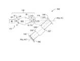
図5AのLPP・GIC型SOCOMO100は、Snペレット(液滴)22が比較的高質量のペレットであり、集束レーザ光線13で照射された場合に、異方性のEUV30が放射されるという点を除き、図4のLPP・GIC型SOCOMO100と同様である。図5AのLPP・GIC型SOCOMO100では、レーザ光源12、集束レンズ17および折り返しミラーFMは、Snペレット(液滴)22が光学軸A1に沿って−X方向に吐出されるように配置されている。このため、略+X方向に放射されるEUV30が生成される。最内部GICシェルの径が限られているため、折り返しミラーFMによる軸方向の広がりが最小限に抑えられている。したがって、レーザ光線13は略光学軸A1に沿ってGICミラーMGを一方向に進行し、EUVは、GICミラーMGを反対方向に通過し、中間焦点IFに向かう。 The LPP / GIC-
図5Bは、図5Aと同様の図であるが、LPP・GIC型SOCOMO100は、RCED37を備えている。RCED37は、中間焦点FSが形成される位置、または、その付近において、開口絞りASに隣接して配置されている。 FIG. 5B is a view similar to FIG. 5A, but the LPP /
図6AのLPP・GIC型SOCOMO100は、表面29を有する比較的高質量の可動固体LPPターゲット27をLPPターゲットシステム40が備えている点を除いて、図5AのLPP・GIC型SOCOMO100と同様である。様々の例において、LPPターゲット材料は、SnまたはXeを含んでもよい。LPPターゲットシステム40は、ターゲット駆動部31(例えば、モータ)を有するターゲットアセンブリ41と、ターゲット駆動部31に取り付けられる駆動軸32と、駆動軸32に取り付けられる取付板MPとを備えている。LPPターゲット27は、取付板MPに取り付けられる。レーザ光源12からの入射レーザ光線13は、軸方向に沿って−X方向にGICミラーMGを進行するように導かれ、LPPターゲット27の表面29に入射してLPP24を形成する。可動ターゲット27により、レーザ光線13をレーザパルス毎に異なる位置でLPPターゲット27の表面29に入射させることが可能となったり、ターゲット位置毎にレーザパルス数を限定してレーザ光線13を照射させることが可能となったりする。LPPターゲット27上に形成されたLPP24からのEUV30は、一般に+X方向に放射され、レーザ光線13の進行方向と逆方向に向かってGICミラーMGを通過する。 The LPP /
図6Bは、図6Aと同様の図であって、回転円板状の固体LPPターゲット27を有するLPPターゲットシステム40の一実施形態例を示している。なお、LPPターゲット27の表面29は、円板面というよりは円板縁である。以下、LPPターゲットシステム40の実施形態について、より詳細に議論する。図6A及び図6BのLPP・GIC型SOCOMO100の実施形態は、両方ともRCED37を備えている。 FIG. 6B is a view similar to FIG. 6A showing an example embodiment of an
(ターゲットの一実施形態例)
図7Aは、図6AのLPPターゲットシステムの詳細な概略側面図である。LPPターゲットシステム40は、真空チャンバ42を備えている。真空チャンバ42は、内部43及び開口部44を有する。開口部44はフランジ45に囲まれており、そのフランジ45は真空チャンバ42をLPP・GIC型SOCOMO100用の大型真空チャンバ(図示せず)に接続するために使用される。(Example of target embodiment)
FIG. 7A is a detailed schematic side view of the LPP target system of FIG. 6A. The
LPPターゲットシステム40は、上記ターゲットアセンブリ41を備えている。ターゲットアセンブリ41は、LPPターゲット27を支持する。ターゲットアセンブリ41は、レーザ光線13がLPPターゲット27の表面29上を走査(例えば、ラスタ走査、螺旋走査等)することができるようにLPPターゲット27を平行移動及び/または回転するように構成されている。 The
図7Bに示されるように、一実施形態例では、LPPターゲット27は、コーティング52を有する基板(例えば、ガラス、セラミック、金属等)50である。なお、コーティング52は、例えば、SnまたはXe等のLPP生成材料からなる。コーティング52の厚みTHは、例えば、1から5ミクロンである。一実施形態例では、基板50は、半導体製造に使用される標準的な未使用のレチクルである。したがって、こうした基板用の処理装置が既に開発されており、その処理装置が直ちに利用可能であるという利点がある。他の実施形態例において、基板50は、コーティング52で覆われている点を除き、データ保存用の標準的な未使用のコンパクトディスク(CD)である。標準的な処理装置は、このような基板に対しても利用可能である。上記2種類の基板は、低コストで再生及び再利用することが可能である。 As shown in FIG. 7B, in one example embodiment, the
また、図7Cの正面図に示されるように、LPPターゲットシステム40は、第1カセット60N及び第2カセット60Uを備えている。第1カセット60Nは複数の新しいLPPターゲット27を保存し、第2カセット60Uは複数の使用済LPPターゲット27を保存する。また、LPPターゲットシステム40は、ターゲット処理システム62を備えている。ターゲット処理システム62は、可動ターゲットホルダ64と協働して、取付板MPから複数の使用済LPPターゲット27を取り除き、これらを(経路P1を通じて)保存用の第2カセット60Uに移動し、第1カセット60Nから新しい複数のターゲットを(経路P2を通じて)取り出して取付板MPに設置するように構成されている。一実施形態例において、ターゲット処理システム62は、真空係止ロボットを利用する。他の実施形態では、複数の使用済LPPターゲット27を第2カセット60Uに移動し、新たなLPPターゲットを第1カセット60Nから取り出す移動(平行移動)ターゲットアセンブリ41が備えられている。この特別な実施形態は、軽量型LPPターゲット27に最適である。 As shown in the front view of FIG. 7C, the
図7Dに示される他の実施形態では、一組のターゲットアセンブリ41が備えられている。一方のターゲットアセンブリ41は、使用済ターゲット27を取り除いて新しいターゲットを交換するために「オフライン」状態になっている。他方のターゲットアセンブリ41は、「オンライン」状態になっており、LPP24を生成するために使用される。 In another embodiment shown in FIG. 7D, a set of
図8Aは、円板型LPPターゲット27を備えた図6BのLPPターゲットシステム40の一例の詳細な概略側面図である。図8Aにおいて、LPPターゲット27の表面29は、円板の表側面というよりは縁に位置する部分である。ターゲットアセンブリ41は、LPPターゲット27を駆動するためにここでも使用されている。しかし、LPPターゲット27は、LPPターゲット27がZ軸周りに回転駆動される際にレーザ光線13がLPPターゲット27の縁に照射されるように、方向付けされている。 FIG. 8A is a detailed schematic side view of an example of the
図8Bは、LPPターゲット27の一例の斜視図である。図8Cは、8C−8Cに沿って切断したLPPターゲット27の一例の断面図であり、LPP生成材料のコーティング52で縁51が被覆されたLPPターゲット27の基板50を示している。このため、LPPターゲット27の表面29を規定するコーティング52が形成される。コーティング52の幅Wは、例えば、1から5mmであり、コーティング52の厚みTHは、例えば、1から5ミクロンである。 FIG. 8B is a perspective view of an example of the
また、図8AのLPPターゲットシステム40は、溶融源70を備えている。溶融源70は、レーザ光線13がLPPターゲット27の表面29に入射する位置とは反対側に配置される。溶融源70は、LPPターゲット27の表面29に照射されるエネルギー光線72を放射する。エネルギー光線72は、局所的にコーティング52を溶融させて、LPPターゲット27の表面29を再生する。溶融源70には、例えば、エネルギー光線システム、レーザ、加熱素子、フィラメント等が含まれる。表面仕上げモニタ80は、エネルギー光線72がLPPターゲット27の表面29に入射する位置に対応して配置されており、LPPターゲット27の再生済(再仕上げ済)の表面29を監視する。折り返しミラー81は、表面仕上げモニタ80によるLPPターゲット27の再生済の表面29の監視をわかり易く説明するために図示されている。 The
一実施形態例において、LPPターゲットシステム40は、コントローラ90を備えている。コントローラ90は、ターゲット駆動部31、溶融源70および表面仕上げモニタ80に動作可能に接続されている。また、コントローラ90は、LPPターゲットシステム40の全体的な動作を制御するように構成されている。コントローラ90は、例えば、コンピュータ読み取り可能な媒体(メモリ)に複数の指示(ソフトウェア)を記録可能なコンピュータを備えている。コントローラ90は、当該コンピュータに(搭載されたプロセッサを介して)LPPターゲットシステム40を操作してLPP24を生成する指示を実行する。コントローラ90の動作としては、例えば、LPP源24の生成中においてコーティング52の厚みTHが減少するにつれて、LPPターゲット27をレーザ光線13の方向に移動させることが挙げられる。 In one example embodiment, the
図8Dは、ターゲットアセンブリ41の一実施形態例の部分拡大図である。図8Dに示されるように、駆動軸32は、仕切り33Dを備えた冷却チャネル33を有している。また、LPPターゲット27は、内部ターゲットチャンバ28を有する。駆動軸32の冷却チャネル33と内部ターゲットチャンバ28とは、流体接続されている。このため、上記の通り、冷却液CFが冷却液源CFSから冷却チャネル33を介して内部ターゲットチャンバ28に向かって流れ、そして、冷却液源CFSに戻ることができる。他の冷却構成は、ここで説明した一例の範囲を超えることを意図している。このような冷却システムは、高反復率の実現にとって望ましいものであるが、これは、付随するコーティング52の選択加熱によってLPPターゲット27の表面29が劣化し得るからである。 FIG. 8D is a partially enlarged view of an example embodiment of
(多層第1ミラーのないSOCOMO)
LPP・GIC型SOCOMO100の一構成例では、多層コート「第1ミラー」が設けられていない。即ち、EUV30が最初に入射する(最初に反射する)ミラーまたはミラー部が、反射面の主要部分を覆う多層コーティング18を有していない。LPP・GIC型SOCOMO100の他の構成例では、第1ミラーは、実質的に斜入射ミラーである。例えば、診断目的で、反射面の僅かな部分(即ち、非主要部分)のみに多層コーティング18が設けられている。(SOCOMO without multilayer first mirror)
In one configuration example of the LPP /
LPP・GIC型SOCOMO100の主な利点は、その性能が多層被覆反射面の残存に依存しない点にある。一実施形態例に係るGICミラーMGは、例えば、図9に示されるGICシェルM1等のような、少なくとも一つの区画化GICシェルが備えている。GICシェルM1は、2つのミラー区画、即ち、第1面S1を有するミラー区画M1Aと、第2面S2を有するミラー区画M1Bとを有することが示されている。第1面S1により第1反射が行われ(したがって、「第1ミラー」であり)、第2面S2により第2反射が行われる。なお、第2反射はLPP24の視線上に位置しない。一実施形態例では、第2面S2が多層コーティング18を支持する。これは、EUV30が一旦反射されると、その強度が相当弱められると共に、通常はLPP24が視線上に位置しないので、多層コーティング18に入射するイオン及び中性原子の量が最小になるからである。また、放射線は、第2反射において第2面S2に斜入射する。このため、最終的に多層コーティング18が損傷するリスクはより少なくなる。 The main advantage of the LPP /
(SOCOMOの寿命)
本発明に係るLPP・GIC型SOCOMO100の他の利点は、その見込み寿命が1年を超えており、半導体製造で使用されるEUVリソグラフィシステムにおいて商業的に実現可能な寿命となっている点にある。他の利点としては、LPP・GIC型SOCOMO100は、LPPターゲットシステム40が、注入されるSnペレット(液滴)22に基づく必要がなく、むしろ、固体LPPターゲット27(例えば、図6A及び図6Bを参照)を採用する実施形態をサポートしている点にある。(SOCOMO life)
Another advantage of the LPP / GIC-
(GIC型SOCOMO対NIC型SOCOMO)
LPP・NIC型SOCOMO10とLPP・GIC型SOCOMO100とには、あるトレードオフの関係が成立する。例えば、LPP24からのEUV30の特定の集光角度に関しては、LPP・NIC型SOCOMO10は、LPP・GIC型SOCOMO100に比して、よりコンパクトに設計することができる。(GIC type SOCOMO vs. NIC type SOCOMO)
A certain trade-off relationship is established between the LPP /
また、LPP・NIC型SOCOMO10は、原則、(光学軸A1に対して)90°を超える角度で、光源から放射されたEUV30を集光するように設計することができ、集光効率をより高めることができる。しかし、NICの径が過度に大きくなる、または、EUV30が中間焦点IFにおいて光学軸A1となす角度が過度に大きくなるので、通常、上記の利点が実際に利用されることはない。 In addition, the LPP / NIC type SOCOMO 10 can be designed to condense the
また、LPP・GIC型SOCOMO100により生成される遠隔フィールドの強度分布は、GICシェルM1の厚みの影と複数のGICミラーMGを支持する機械的構造が原因で、さらに広がる。しかし、本発明において以下議論する実施形態においては、GICの表面が、表面補正機能を有している。この表面補正機能により、GICの複数のシェルの厚みによる陰影効果が低減され、中間焦点IFにおける中間焦点FSの均一性が向上する。 Further, the intensity distribution of the remote field generated by the LPP /
さらに、LPP・GIC型SOCOMO100は、LPP・NIC型SOCOMO10に比して、中間焦点IFにおいて一般的により大きな中間焦点FSを形成する。このような相違の大きさは、主としてGICミラーの形状誤差に関係があり、技術進歩に伴い低減されつつある。 Further, the LPP /
全体としては、LPP・GIC型SOCOMO100から得られる利益、即ち、より長い動作寿命、費用の低減、簡素であること、維持費用及び問題の低減が、上記のトレードオフを上回るものであると一般に考えられている。 Overall, we generally believe that the benefits gained from the LPP /
(塵埃低減装置を備えたLPP・GIC型SOCOMO)
図10は、図3Bと同様に、LPP・GIC型SOCOMO100を一般化した一実施形態例を示している。ただし、ここでは、LPP・GIC型SOCOMO100は、塵埃低減装置(DMD)200を備えている。塵埃低減装置(DMD)200は、LPP24とGICミラーMGとの間に配置されている。DMD200は、隠れ線で図示されている。これは、典型的には、EUV30がDMD200を通過する際に、DMD200が、LPP24からの他の有害なイオン及び粒子(例えば、エネルギーSnイオン等)を遮断するという事実を示すためである。また、DMD200は、GICミラーMGに形成される塵埃(Sn等)を除去するように構成されている。また、図10には、RCED37が図示されている。(LPP / GIC type SOCOMO with dust reduction device)
FIG. 10 shows an embodiment in which the LPP /
DMD200には、例えば、磁界ベースのDMDや複数の放射金属ラメラに基づくDMD等、LPP・NIC型SOCOMO技術で使用されるDMDが含まれる。DMDは、例えば、米国特許第7,230,258号、7,423,275号、7,372,049号、7,355,190号、7,193,229号、7,180,083号、6,963,071号において言及されており、当該特許は本出願に援用される。また、DMDは、例えば、D.J.W.Klunder等の論文「EUVリソグラフィ用のSnベースの光源に対する塵埃低減及び洗浄戦略(Debris Mitigation and Cleaning Strategies for Sn−Based Sources for EUV Lithography)」(SPIE論文集、Vol.5751、第943−951頁)にも記載されており、当該論文は本出願に援用される。 The
(LPP・GIC型SOCOMO用GICミラーの一例)
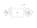
図11は、LPP・GIC型SOCOMO100用のGICミラーMGの一例の概略部分側面図である。光学設計上、図11のGICミラーMGは、実際には、図12に示されるように、光学軸A1周りに対称な円筒状の8つの入れ子状GICシェル210から構成されている。また、GICシェル210の数を最小化するために、3つの最内部GICシェル210は楕円形を有し、5つの最外部GICシェル210は、楕円形かつ双曲線状の断面を有する軸外し二重反射設計に基づいている。これは、欧州特許出願公報第EP1901126A1(発明の名称:コレクタ光学システム)等に記載されており、当該公報は本出願に援用される。図11は、2つの最外部GICシェル210を図示している。当該最外部GICシェル210は、それぞれ、楕円形部210E及び双曲線部210Hを有する。また、図11には、光源焦点SF、仮想共通焦点VCFおよび中間焦点IFに加えて、GICシェル210の楕円形部210E及び双曲線部210Hそれぞれの軸AE及び軸AHが図示されている。仮想共通焦点VCFと中間焦点IFとの間の距離は、ΔLである。仮想共通焦点VCFは、光学軸A1から距離Δr分だけオフセットされている。光学軸A1周りに楕円形部210E及び双曲線部210Hの断面を1回転させることで、光学面全体が得られる。(Example of GPP mirror for LPP / GIC type SOCOMO)
FIG. 11 is a schematic partial side view of an example of the GIC mirror MG for the LPP /
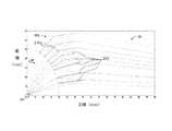
GICミラーMGの一例の設計例が、下記の表1及び表2に掲載されている。当該設計の主な光学パラメータは、a)LPP24と中間焦点IFとの間の距離ΔL=2400mm、b)LPP側の最大集光角度=70.7°である。一実施形態例において、各GICシェル210は、Ruコーティングを有しており、各EUV波長での反射率が改善されている。複数のGICシェル210の光学面がRuで被覆された場合、波長13.5nmのEUV30に対するGICミラーMGの理論上の集光効率は、LPP24からの2πステラジアン放射に対して37.6%である。 A design example of an example of the GIC mirror MG is listed in Tables 1 and 2 below. The main optical parameters of the design are a) the distance ΔL = 2400 mm between the
LPP・EUV光源は、放電生成プラズマ(DPP)EUV光源に比して随分小型(約10分の1)である。このため、LPP24を使用すれば、GICミラー出力とイルミネータ入力との間の面積効率(etendue)を良好に一致させることができる。特に、LPP24における集光角度は、GICミラーMGとイルミネータの面積効率との不一致による効率損失が無視できる程度の状態または極めて限定的な状態で、極めて大きな値に増加し得る。一実施形態例において、集光角度は70度を超える。 The LPP / EUV light source is considerably smaller (about 1/10) than the discharge-generated plasma (DPP) EUV light source. For this reason, if the
特定の集光器の光学設計に関して、遠隔フィールドにおける強度分布の均一性がDPP源よりも劣る傾向にあるという点で、LPP24の寸法には問題がある。事実、LPP24は小型であるので、DPP源に比して、複数のGICシェル210の厚みによる遠隔フィールドの影がより急激になる傾向がある。 For certain concentrator optical designs, the
こうした効果を少なくとも部分的に相殺するために、各GICシェル210に対して表面形状(即ち光学プロファイル)補正が加えられ、遠隔フィールドにおける強度分布の均一性が改善されている(例えば、国際特許出願公報第WO2009−095219A1号(発明の名称:EUV及びX線を適用する改良型斜入射集光器光学システム)を参照。なお、当該公報は本出願に援用される。)。このように、GICミラーMGの一実施形態例では、各GICシェル210は、GICシェルの2つの縁において、ゼロに等しい多項式補正(放物線補正)が重畳されている。なお、その値は、最大でも0.01mmである。 To at least partially offset these effects, a surface shape (ie, optical profile) correction is applied to each
表1及び表2には、図10に示されるGICミラーMGの一設計例が示されている。「ミラー番号」は、特定のGICシェル210の番号であり、最内部GICシェルから順に最外部GICシェルまで付与されている。 Tables 1 and 2 show one design example of the GIC mirror MG shown in FIG. The “mirror number” is a number of a

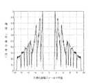
図13Aは、GICシェルのプロファイルを補正しない場合における、中間焦点IFにおける正規化遠隔フィールド位置と、そこに入射する光線の強度(任意の単位)との関係を表すプロットである。当該プロットは、中間焦点IFにおいて形成されるLPP24の中間画像(即ち、「中間焦点」FS)の均一性に関する測定値である。LPP24は、0.2mmの径を有する球体としてモデル化されている。 FIG. 13A is a plot showing the relationship between the normalized far field position at the intermediate focus IF and the intensity (in arbitrary units) of the light incident thereon when the GIC shell profile is not corrected. The plot is a measure of the uniformity of the intermediate image of the LPP 24 (ie, “intermediate focus” FS) formed at the intermediate focus IF. The
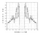
図13Bは、複数のGICシェル210に上記補正を適用したことを除いて、先と同様のプロットである。図13Aのプロットと図13Bのプロットとを比較すると、図13Bの強度においては振幅が相当低減されており、複数のGICシェル210の表面形状を補正した結果、中間焦点IFにおける中間焦点FSでの遠隔フィールド均一性が著しく改善されていることがわかる。 FIG. 13B is a plot similar to the previous plot except that the above correction is applied to a plurality of
(LPP・GIC型SOCOMOを備えたEUVリソグラフィシステム)
図14は、本発明に係るEUVリソグラフィシステム300の一例である。EUVリソグラフィシステム300は、例えば、米国特許出願第US2004/0265712A1号、第US2005/0016679A1号、第US2005/0155624A1号に開示されており、当該出願は本出願に援用される。(EUV lithography system with LPP / GIC type SOCOMO)
FIG. 14 is an example of an
リソグラフィシステム300は、システム軸ASyおよびEUV光源LSを備えている。EUV光源LSは、例えば、上記の何れか一つのLPPターゲットシステム40を備えている。LPPターゲットシステム40は、λ=13.5nmの作用EUV30を放出するLPP24を生成する。 The
リソグラフィシステム300は、例えば、上記のようなEUV・GICミラーMGを備えている。一実施形態例において、EUV・GICミラーMGは、米国特許出願第12/592,735号に記載されているように冷却される。なお、当該米国特許出願は、本出願に援用される。EUV・GICミラーMGは、EUV光源LSの下流側の近傍に配置されており、集光器軸ACがシステム軸ASyに沿うようにして配置されている。EUV・GICミラーMGは、光源焦点SFに位置するEUV光源LSからの作用EUV30(即ち、光線LR)を集光する。そして、集光された放射光線は、中間焦点IFに中間光源像IS(即ち、中間焦点FS)を結像する。LPP・GIC型SOCOMO100は、一例において、EUV光源LS及びGICミラーMGを備えている。RCED37は、例示目的で図示されている。 The
照明システム316は、入力端317及び出力端318を有し、システム軸ASyに沿って配置され、入力端317がEUV・GICミラーMG側に配置された状態で、EUV・GICミラーMGの下流側の近傍に配置されている。照明システム316は、入力端317において中間光源像ISからのEUV30を受け、出力端318において略均一なEUV320(即ち、凝縮EUV)を出力する。リソグラフィシステムシステム300が走査型システムである場合、EUV320は、典型的には、反射レチクル336を走査する略均一なライン状またはリングフィールド状のEUV30として、反射レチクル336上に形成される。 The
投影光学システム326は、(屈折した)システム軸ASyに沿って、照明システム316の下流に配置されている。投影光学システム326は、照明システム316の出力端318に対向する入力端327と、反対側の出力端328を有する。反射レチクル326は投影光学システム326の入力端327に隣接して配置されており、半導体ウエハ340は投影光学システム326の出力端328に隣接して配置されている。反射レチクル336は、半導体ウエハ340に転写されるパターン(図示せず)を有し、半導体ウエハ340は感光性コーティング(例えば、フォトレジスト層)342を有する。動作時において、均一化されたEUV320は、反射レチクル336を照射し、レチクル336によって反射される。そして、投影光学システム326によって、半導体ウエハ340の感光性コーティング342の表面上に、レチクル336上のパターンが結像される。リソグラフィシステムシステム300では、レチクル像が感光性コーティング342の表面上を走査し、露光フィールド上にパターンが形成される。典型的には、反射レチクル336と半導体ウエハ340とを同期させて移動させることにより、走査が実行される。 The projection optical system 326 is arranged downstream of the
レチクルパターンが一旦半導体ウエハ340に結像され、記録されると、パターン化された半導体ウエハ340は、標準的なフォトリソグラフィ技術及び半導体プロセス技術を使用して処理される。その結果、複数の集積回路(IC)チップが形成される。 Once the reticle pattern is imaged and recorded on the
なお、一般的にリソグラフィシステム300の構成要素は、共通の屈折した軸ASyに沿って配置されることが図14に図示されている。当業者であれば、例えば、照明システム316や投影光学システム326の様々な構成 要素の入口軸及び出口軸がオフセットされる場合もあり得ることは、理解される。 Note that it is generally illustrated in FIG. 14 that the components of the
当業者には明白であるが、本発明の精神及び範囲を逸脱することなく、本発明に対して様々な修正及び変更を加えることができる。したがって、本発明は、添付の特許請求の範囲及びその均等範囲内において本発明の修正及び変更を包含する。
It will be apparent to those skilled in the art that various modifications and variations can be made to the present invention without departing from the spirit and scope of the invention. Accordingly, the present invention includes modifications and variations of this invention within the scope of the appended claims and their equivalents.
Claims (24)
Translated fromJapanese光源集光モジュール軸に沿ってパルスレーザ光線を生成するレーザと、
前記パルスレーザ光線を受光して、EUVを生成するレーザ生成プラズマ(LPP)を生成するように構成された表面を有する固体LPPターゲットであって、内部を冷却液が流れる内部ターゲットチャンバを有する固体LPPターゲットと、
入射端及び出射端を有し、前記入射端において前記EUVを受光し、前記受光したEUVの焦点を、前記出射端に隣接する中間焦点に合わせるように配置される斜入射集光器(GIC)ミラーと
を備える、光源集光モジュール。A light source collection module for an extreme ultraviolet (EUV) lithography system comprising:
A laser that generates a pulsed laser beam along the axis of the light source condensing module;
Wherein by receiving the pulsed laser beam,a solid LPP target having a surface configured to generate EUV generation,Relais chromatography The generated plasma(LPP), the internal target chamber flowing through the cooling fluid Having a solid LPP target ;
A grazing incidence collector (GIC) having an entrance end and an exit end, arranged to receive the EUV at the entrance end, and to focus the received EUV on an intermediate focus adjacent to the exit end A light source condensing module comprising a mirror.
前記第1反射面は、前記第1反射面の主要部分を覆う多層コーティングを有していない
請求項1に記載の光源集光モジュール。The GIC mirror has a first reflecting surface;
2. The light source condensing module according to claim 1, wherein the first reflecting surface does not have a multilayer coating covering a main part of the first reflecting surface.
請求項1または2に記載の光源集光モジュール。The light source condensing module according to claim 1, wherein the GIC mirror has a Ru coating.
請求項2に記載の光源集光モジュール。The light source condensing module according to claim 2, wherein the GIC mirror has a multilayer coating.
前記第2反射面は、多層コーティングを有する
請求項2に記載の光源集光モジュール。The GIC mirror has at least one partitioned GIC shell having the first reflective surface and the second reflective surface;
The light source condensing module according to claim 2, wherein the second reflecting surface has a multilayer coating.
請求項1から5のいずれかに記載の光源集光モジュール。6. The light source condensing module according to claim 1, wherein the laser beam travels through the GIC mirror from the emission end to the incident end and reaches the surface of the LPP target.
請求項6に記載の光源集光モジュール。The light source condensing module according to claim 6, wherein the surface of the LPP target has a coating of an LPP generating material formed on a substrate.
請求項1から7のいずれかに記載の光源集光モジュール。The light source condensing module according to claim 1, wherein the surface of the LPP target includes one of Sn and Xe.
請求項1から8のいずれかに記載の光源集光モジュール。The light source condensing according to any one of claims 1 to 8, further comprising a radiation concentrating enhancement device arranged between the exit end of the GIC mirror and the intermediate focal point and configured to direct EUV toward the focal point. module.
請求項1から9のいずれかに記載の光源集光モジュールと、
前記中間焦点で焦点が合わせられた前記EUVを受光して凝縮EUVを形成し、前記凝縮EUVを前記反射レチクルに照射するように構成されるイルミネータと
を備える、EUVリソグラフィシステム。An extreme ultraviolet (EUV) lithography system for illuminating a reflective reticle,
A light source condensing module according to any one of claims 1 to 9,
An EUV lithography system comprising: an illuminator configured to receive the EUV focused at the intermediate focus to form condensed EUV and to irradiate the reflective EUV onto the reflective reticle;
前記反射レチクルの下流に配置され、前記反射レチクルから反射されたEUVを受光し、そこから前記感光性半導体ウエハ上に前記パターン化された画像を形成するように構成される投影光学システムをさらに備える
請求項10に記載のEUVリソグラフィシステム。The EUV lithography system is an EUV lithography system for forming a patterned image on a photosensitive semiconductor wafer;
A projection optical system disposed downstream of the reflective reticle and configured to receive EUV reflected from the reflective reticle and form the patterned image on the photosensitive semiconductor wafer therefrom; The EUV lithography system according to claim 10.
入射端及び出射端を有する斜入射集光器(GIC)ミラーを軸に沿って配置することと、
ターゲット面を有する固体LPPターゲットを有するLPPターゲットシステムを前記GICミラーの前記入射端に隣接して配置することと、
前記LPPターゲットを移動させながら、パルスレーザ光線を前記GIC軸に沿って前記出射端から前記入射端まで前記GICを通過させて前記ターゲット面まで送信し、前記EUVを発する前記LPPを形成することと、
前記GICミラーの前記入射端において、前記GICミラーにより、前記LPPからの前記EUVの一部を集光し、前記GICミラーの前記出射端から出射する前記集光された放射線を導き、中間焦点に焦点を形成することと
を備え、
前記固体LPPターゲットは、内部ターゲットチャンバを有し、前記内部ターゲットチャンバ内には冷却液が流れる、方法。A method of collecting extreme ultraviolet light (EUV) from laser-produced plasma (LPP),
Arranging a grazing incidence collector (GIC) mirror having an entrance end and an exit end along an axis;
Placing an LPP target system having a solid LPP target having a target surface adjacent to the entrance end of the GIC mirror;
While moving the LPP target, a pulsed laser beam is transmitted along the GIC axis from the exit end to the entrance end through the GIC to the target surface to form the LPP that emits the EUV. ,
At the entrance end of the GIC mirror, the GIC mirror condenses a part of the EUV from the LPP, and guides the collected radiation emitted from the exit end of the GIC mirror to an intermediate focus.e Bei and forming a focalpoint,
The method, wherein the solid LPP target has an internal target chamber and a coolant flows in the internal target chamber .
請求項12に記載の方法。A radiation condensing enhancement device is disposed between the exit end of the GIC mirror and the intermediate focus, and further comprising guiding EUV that is not normally guided to the focus by the GIC mirror to the focus. Item 13. The method according to Item 12.
前記LPP生成材料は、SnまたはXeを含む
請求項12または13に記載の方法。Further comprising providing the target as a movable substrate having a coating of LPP-generating material;
The method according to claim 12 or 13, wherein the LPP-generating material comprises Sn or Xe.
前記表面及び前記縁の少なくともいずれかに前記コーティングを施すことをさらに備える
請求項14に記載の方法。The substrate has a surface and an edge;
The method of claim 14, further comprising applying the coating to at least one of the surface and the edge.
請求項12から15のいずれかに記載の方法。16. A method according to any of claims 12 to 15, further comprising providing a first reflective surface on the GIC mirror that does not have a multilayer coating.
請求項12から16のいずれかに記載の方法。17. A method according to any of claims 12 to 16, wherein the GIC mirror has a Ru coating.
請求項12から17のいずれかに記載の方法。18. A method according to any of claims 12 to 17, wherein the GIC mirror has a multilayer coating.
前記区画化GICシェルは、前記第1反射面および第2反射面を有し、
前記第2反射面は、前記多層コーティングを有する
請求項18に記載の方法。The GIC mirror comprises at least one partitioned GIC shell;
The partitioned GIC shell has the first reflective surface and the second reflective surface,
The method of claim 18, wherein the second reflective surface comprises the multilayer coating.
請求項12から19のいずれかに記載の方法。20. A method according to any of claims 12 to 19, further comprising forming condensed EUV from the EUV at the intermediate focus and irradiating the reflective reticle with the condensed EUV.
請求項20に記載の方法。21. The method of claim 20, further comprising receiving the EUV reflected from the reflective reticle and utilizing the projection optical system to form the patterned image on the photosensitive semiconductor wafer. .
光源集光モジュール軸に沿ってパルスレーザ光線を生成するレーザと、
前記パルスレーザ光線を受光して、EUVを生成するレーザ生成プラズマ(LPP)を生成するように構成された表面を有する固体LPPターゲットであって、内部を冷却液が流れる内部ターゲットチャンバを有する固体LPPターゲットと、
入射端及び出射端を有する斜入射集光器(GIC)ミラーと、を備え、
前記斜入射集光器(GIC)ミラーは、
楕円形を有する3つの同心円状に配置された最内部GICシェルと、
前記3つの最内部GICシェルを同心円状に取り囲み、前記EUVの二重反射を実現する5つの最外部GICシェルと
を備え、
前記最外部GICシェルは、
それぞれが楕円形部と双曲線部とを、前記楕円形部の軸および前記双曲線部の軸に一致しない共通軸周りに回転させることにより規定される曲率を有しており、
前記入射端に入り、前記出射端から出るEUVを単反射させるように構成される
光源集光モジュール(SOCOMO)。A light source concentrator module (SOCOMO) for an extreme ultraviolet (EUV) lithography system,
A laser that generates a pulsed laser beam along the axis of the light source condensing module;
A solid LPP target having a surface configured to receive the pulsed laser beam and generate a laser-produced plasma (LPP) that generates EUV, and having an internal target chamber through which a coolant flows. Target,
A grazing incidence collector (GIC) mirror having an entrance end and an exit end;
The grazing incidence collector (GIC) mirror is
Three innermost GIC shells arranged in concentric circles having an oval shape;
And five outermost GIC shells that concentrically surround the three innermost GIC shells and realize double reflection of the EUV,
The outermost GIC shell is
Each having a curvature defined by rotating the elliptical portion and the hyperbolic portion about a common axis that does not coincide with the axis of the elliptical portion and the axis of the hyperbolic portion;
It is configured to single-reflect EUV that enters the entrance end and exits from the exit end.
Light source condensing module (SOCOMO).
請求項22に記載の光源集光モジュール(SOCOMO)。23. The light source condensing module (SOCOMO) according to claim 22, wherein each of the GIC shells has a thickness, and has a polynomial surface shape correction that uniformizes a change in an intermediate image due to the thickness of the GIC shell.
Applications Claiming Priority (4)
| Application Number | Priority Date | Filing Date | Title |
|---|---|---|---|
| US33570010P | 2010-01-11 | 2010-01-11 | |
| US61/335,700 | 2010-01-11 | ||
| US12/803,075 | 2010-06-18 | ||
| US12/803,075US8330131B2 (en) | 2010-01-11 | 2010-06-18 | Source-collector module with GIC mirror and LPP EUV light source |
Publications (2)
| Publication Number | Publication Date |
|---|---|
| JP2011142323A JP2011142323A (en) | 2011-07-21 |
| JP5694784B2true JP5694784B2 (en) | 2015-04-01 |
Family
ID=44257814
Family Applications (1)
| Application Number | Title | Priority Date | Filing Date |
|---|---|---|---|
| JP2011000143AExpired - Fee RelatedJP5694784B2 (en) | 2010-01-11 | 2011-01-04 | Light source condensing module with GIC mirror and LPP / EUV light source |
Country Status (4)
| Country | Link |
|---|---|
| US (1) | US8330131B2 (en) |
| JP (1) | JP5694784B2 (en) |
| DE (1) | DE102010056553B4 (en) |
| NL (1) | NL2005960C2 (en) |
Families Citing this family (17)
| Publication number | Priority date | Publication date | Assignee | Title |
|---|---|---|---|---|
| JP5315100B2 (en)* | 2009-03-18 | 2013-10-16 | 株式会社ニューフレアテクノロジー | Drawing device |
| US8587768B2 (en) | 2010-04-05 | 2013-11-19 | Media Lario S.R.L. | EUV collector system with enhanced EUV radiation collection |
| US9057962B2 (en)* | 2010-06-18 | 2015-06-16 | Media Lario S.R.L. | Source-collector module with GIC mirror and LPP EUV light source |
| JP2012028759A (en)* | 2010-06-29 | 2012-02-09 | Asml Netherlands Bv | Euv radiation source and method for generating euv radiation |
| US8344339B2 (en)* | 2010-08-30 | 2013-01-01 | Media Lario S.R.L. | Source-collector module with GIC mirror and tin rod EUV LPP target system |
| US8746975B2 (en) | 2011-02-17 | 2014-06-10 | Media Lario S.R.L. | Thermal management systems, assemblies and methods for grazing incidence collectors for EUV lithography |
| US8731139B2 (en) | 2011-05-04 | 2014-05-20 | Media Lario S.R.L. | Evaporative thermal management of grazing incidence collectors for EUV lithography |
| WO2013041323A1 (en) | 2011-09-22 | 2013-03-28 | Asml Netherlands B.V. | Radiation source |
| TWI596384B (en)* | 2012-01-18 | 2017-08-21 | Asml荷蘭公司 | Light source collector element, lithography device and component manufacturing method |
| DE102013002064A1 (en) | 2012-02-11 | 2013-08-14 | Media Lario S.R.L. | SOURCE-COLLECTOR MODULES FOR EUV LITHOGRAPHY USING A GIC MIRROR AND AN LPP SOURCE |
| US9268031B2 (en)* | 2012-04-09 | 2016-02-23 | Kla-Tencor Corporation | Advanced debris mitigation of EUV light source |
| DE102012220465A1 (en)* | 2012-11-09 | 2014-05-15 | Carl Zeiss Smt Gmbh | EUV collector |
| CN103869633B (en)* | 2014-04-11 | 2015-08-05 | 哈尔滨工业大学 | Extreme Ultraviolet Lithography Source is collected and illuminator |
| US9609731B2 (en) | 2014-07-07 | 2017-03-28 | Media Lario Srl | Systems and methods for synchronous operation of debris-mitigation devices |
| US9859226B1 (en) | 2016-12-13 | 2018-01-02 | International Business Machines Corporation | Core-shell particles for anti-tampering applications |
| CN109029921B (en)* | 2018-08-03 | 2024-04-26 | 中国电子科技集团公司第十一研究所 | Target simulator for focusing and adjusting the axis of multi-sensor optoelectronic equipment |
| US11217357B2 (en)* | 2020-02-10 | 2022-01-04 | Sigray, Inc. | X-ray mirror optics with multiple hyperboloidal/hyperbolic surface profiles |
Family Cites Families (24)
| Publication number | Priority date | Publication date | Assignee | Title |
|---|---|---|---|---|
| US6566668B2 (en) | 1997-05-12 | 2003-05-20 | Cymer, Inc. | Plasma focus light source with tandem ellipsoidal mirror units |
| US6963071B2 (en) | 2002-11-25 | 2005-11-08 | Intel Corporation | Debris mitigation device |
| US7217940B2 (en)* | 2003-04-08 | 2007-05-15 | Cymer, Inc. | Collector for EUV light source |
| US6841322B1 (en) | 2003-06-30 | 2005-01-11 | Intel Corporation | Detecting erosion in collector optics with plasma sources in extreme ultraviolet (EUV) lithography systems |
| US7230258B2 (en) | 2003-07-24 | 2007-06-12 | Intel Corporation | Plasma-based debris mitigation for extreme ultraviolet (EUV) light source |
| FR2860385B1 (en)* | 2003-09-26 | 2007-06-01 | Cit Alcatel | SOURCE EUV |
| US7423275B2 (en) | 2004-01-15 | 2008-09-09 | Intel Corporation | Erosion mitigation for collector optics using electric and magnetic fields |
| US7405804B2 (en)* | 2004-10-06 | 2008-07-29 | Asml Netherlands B.V. | Lithographic apparatus with enhanced spectral purity, device manufacturing method and device manufactured thereby |
| US20080099935A1 (en)* | 2004-11-09 | 2008-05-01 | Wilhelm Egle | High-Precision Optical Surface Prepared by Sagging from a Masterpiece |
| US7193229B2 (en) | 2004-12-28 | 2007-03-20 | Asml Netherlands B.V. | Lithographic apparatus, illumination system and method for mitigating debris particles |
| US7180083B2 (en) | 2005-06-27 | 2007-02-20 | Cymer, Inc. | EUV light source collector erosion mitigation |
| JP4901874B2 (en)* | 2005-11-02 | 2012-03-21 | ユニバーシティ・カレッジ・ダブリン,ナショナル・ユニバーシティ・オブ・アイルランド,ダブリン | EUV mirror |
| US7372049B2 (en) | 2005-12-02 | 2008-05-13 | Asml Netherlands B.V. | Lithographic apparatus including a cleaning device and method for cleaning an optical element |
| US7910900B2 (en)* | 2006-07-20 | 2011-03-22 | Carl Zeiss Smt Gmbh | Collector for an illumination system |
| ATE528693T1 (en) | 2006-09-15 | 2011-10-15 | Media Lario Srl | OPTICAL COLLECTOR SYSTEM |
| JP5149514B2 (en)* | 2007-02-20 | 2013-02-20 | ギガフォトン株式会社 | Extreme ultraviolet light source device |
| JP5277496B2 (en)* | 2007-04-27 | 2013-08-28 | ギガフォトン株式会社 | Extreme ultraviolet light source device and optical element contamination prevention device of extreme ultraviolet light source device |
| JP5429951B2 (en)* | 2007-04-27 | 2014-02-26 | ギガフォトン株式会社 | Target supply device in EUV light generator |
| EP2083327B1 (en) | 2008-01-28 | 2017-11-29 | Media Lario s.r.l. | Improved grazing incidence collector optical systems for EUV and X-ray applications |
| EP2083328B1 (en) | 2008-01-28 | 2013-06-19 | Media Lario s.r.l. | Grazing incidence collector for laser produced plasma sources |
| JP5133740B2 (en)* | 2008-03-10 | 2013-01-30 | ギガフォトン株式会社 | Extreme ultraviolet light source device |
| JP5580032B2 (en)* | 2008-12-26 | 2014-08-27 | ギガフォトン株式会社 | Extreme ultraviolet light source device |
| US8050380B2 (en)* | 2009-05-05 | 2011-11-01 | Media Lario, S.R.L. | Zone-optimized mirrors and optical systems using same |
| US8587768B2 (en)* | 2010-04-05 | 2013-11-19 | Media Lario S.R.L. | EUV collector system with enhanced EUV radiation collection |
- 2010
- 2010-06-18USUS12/803,075patent/US8330131B2/ennot_activeExpired - Fee Related
- 2010-12-30DEDE102010056553.9Apatent/DE102010056553B4/ennot_activeExpired - Fee Related
- 2011
- 2011-01-04JPJP2011000143Apatent/JP5694784B2/ennot_activeExpired - Fee Related
- 2011-01-06NLNL2005960Apatent/NL2005960C2/ennot_activeIP Right Cessation
Also Published As
| Publication number | Publication date |
|---|---|
| JP2011142323A (en) | 2011-07-21 |
| NL2005960A (en) | 2011-07-12 |
| US8330131B2 (en) | 2012-12-11 |
| US20110168925A1 (en) | 2011-07-14 |
| DE102010056553A1 (en) | 2011-07-14 |
| DE102010056553B4 (en) | 2019-04-04 |
| NL2005960C2 (en) | 2011-08-30 |
Similar Documents
| Publication | Publication Date | Title |
|---|---|---|
| JP5694784B2 (en) | Light source condensing module with GIC mirror and LPP / EUV light source | |
| JP5864154B2 (en) | Light source condensing module with GIC mirror and liquid xenon EUV / LPP target system | |
| JP5898429B2 (en) | Light source condensing module with GIC mirror and tin rod EUV / LPP target system | |
| JP6126798B2 (en) | Radiation source and lithographic apparatus | |
| JP5878120B2 (en) | EUV radiation system and lithographic apparatus | |
| US8884257B2 (en) | Chamber apparatus and extreme ultraviolet light generation system | |
| JP5070264B2 (en) | Source module, radiation source and lithographic apparatus | |
| JP6687691B2 (en) | Radiation source and method for lithography | |
| JP5777951B2 (en) | Light source condensing module with GIC mirror and tin vapor LPP target system | |
| KR20110015660A (en) | Radiation systems, radiation collectors, radiation beam conditioning systems, spectral purity filters for radiation systems, and methods of forming spectral purity filters | |
| JP2013522866A (en) | Radiation source, lithographic apparatus and device manufacturing method | |
| JP6116128B2 (en) | Lithographic apparatus and method | |
| CN119758679A (en) | Extreme ultraviolet radiation source module | |
| JP5740106B2 (en) | EUV radiation generator | |
| JP2012054551A (en) | Source-collector module with gic mirror and xenon ice euv lpp target system | |
| US9057962B2 (en) | Source-collector module with GIC mirror and LPP EUV light source | |
| JP2007208239A (en) | Lithography device and method for manufacturing device | |
| JP5689059B2 (en) | Spectral purity filter, radiation source module, lithographic apparatus and device manufacturing method | |
| JP2013524525A (en) | EUV radiation source and EUV radiation generation method | |
| JP2005294087A (en) | Light source unit, illumination optical device, exposure apparatus, and exposure method | |
| JP6395832B2 (en) | Radiation source components, associated radiation sources and lithographic apparatus | |
| JP2012054548A (en) | Source-collector module with gic mirror and tin wire euv lpp target system | |
| NL2010217A (en) | Source collector apparatus, lithographic apparatus and device manufacturing method. |
Legal Events
| Date | Code | Title | Description |
|---|---|---|---|
| RD02 | Notification of acceptance of power of attorney | Free format text:JAPANESE INTERMEDIATE CODE: A7422 Effective date:20120705 | |
| A621 | Written request for application examination | Free format text:JAPANESE INTERMEDIATE CODE: A621 Effective date:20131225 | |
| A977 | Report on retrieval | Free format text:JAPANESE INTERMEDIATE CODE: A971007 Effective date:20140916 | |
| A131 | Notification of reasons for refusal | Free format text:JAPANESE INTERMEDIATE CODE: A131 Effective date:20140924 | |
| A521 | Request for written amendment filed | Free format text:JAPANESE INTERMEDIATE CODE: A523 Effective date:20141216 | |
| TRDD | Decision of grant or rejection written | ||
| A01 | Written decision to grant a patent or to grant a registration (utility model) | Free format text:JAPANESE INTERMEDIATE CODE: A01 Effective date:20150203 | |
| A61 | First payment of annual fees (during grant procedure) | Free format text:JAPANESE INTERMEDIATE CODE: A61 Effective date:20150205 | |
| R150 | Certificate of patent or registration of utility model | Ref document number:5694784 Country of ref document:JP Free format text:JAPANESE INTERMEDIATE CODE: R150 | |
| R250 | Receipt of annual fees | Free format text:JAPANESE INTERMEDIATE CODE: R250 | |
| R250 | Receipt of annual fees | Free format text:JAPANESE INTERMEDIATE CODE: R250 | |
| R250 | Receipt of annual fees | Free format text:JAPANESE INTERMEDIATE CODE: R250 | |
| R250 | Receipt of annual fees | Free format text:JAPANESE INTERMEDIATE CODE: R250 | |
| R250 | Receipt of annual fees | Free format text:JAPANESE INTERMEDIATE CODE: R250 | |
| LAPS | Cancellation because of no payment of annual fees |