JP5693472B2 - Deformable safety helmet - Google Patents
Deformable safety helmetDownload PDFInfo
- Publication number
- JP5693472B2 JP5693472B2JP2011549621AJP2011549621AJP5693472B2JP 5693472 B2JP5693472 B2JP 5693472B2JP 2011549621 AJP2011549621 AJP 2011549621AJP 2011549621 AJP2011549621 AJP 2011549621AJP 5693472 B2JP5693472 B2JP 5693472B2
- Authority
- JP
- Japan
- Prior art keywords
- shell
- damping
- damping element
- helmet
- support belt
- Prior art date
- Legal status (The legal status is an assumption and is not a legal conclusion. Google has not performed a legal analysis and makes no representation as to the accuracy of the status listed.)
- Expired - Fee Related
Links
- 238000013016dampingMethods0.000claimsdescription100
- 239000000463materialSubstances0.000claimsdescription13
- 230000008878couplingEffects0.000claimsdescription12
- 238000010168coupling processMethods0.000claimsdescription12
- 238000005859coupling reactionMethods0.000claimsdescription12
- 230000006835compressionEffects0.000claimsdescription7
- 238000007906compressionMethods0.000claimsdescription7
- 239000006260foamSubstances0.000claimsdescription5
- 230000008901benefitEffects0.000description5
- 238000010586diagramMethods0.000description5
- 239000000243solutionSubstances0.000description5
- 230000000694effectsEffects0.000description3
- LYCAIKOWRPUZTN-UHFFFAOYSA-NEthylene glycolChemical compoundOCCOLYCAIKOWRPUZTN-UHFFFAOYSA-N0.000description2
- PPBRXRYQALVLMV-UHFFFAOYSA-NStyreneChemical compoundC=CC1=CC=CC=C1PPBRXRYQALVLMV-UHFFFAOYSA-N0.000description2
- XECAHXYUAAWDEL-UHFFFAOYSA-Nacrylonitrile butadiene styreneChemical compoundC=CC=C.C=CC#N.C=CC1=CC=CC=C1XECAHXYUAAWDEL-UHFFFAOYSA-N0.000description2
- 239000004676acrylonitrile butadiene styreneSubstances0.000description2
- 229920000122acrylonitrile butadiene styrenePolymers0.000description2
- 238000005452bendingMethods0.000description2
- DQXBYHZEEUGOBF-UHFFFAOYSA-Nbut-3-enoic acid;etheneChemical compoundC=C.OC(=O)CC=CDQXBYHZEEUGOBF-UHFFFAOYSA-N0.000description2
- 239000005038ethylene vinyl acetateSubstances0.000description2
- 229920001200poly(ethylene-vinyl acetate)Polymers0.000description2
- 239000004800polyvinyl chlorideSubstances0.000description2
- 229920000915polyvinyl chloridePolymers0.000description2
- 238000011084recoveryMethods0.000description2
- 238000000926separation methodMethods0.000description2
- 238000009423ventilationMethods0.000description2
- 241000239290AraneaeSpecies0.000description1
- 239000004831Hot glueSubstances0.000description1
- 239000004698PolyethyleneSubstances0.000description1
- 239000004793PolystyreneSubstances0.000description1
- XUIMIQQOPSSXEZ-UHFFFAOYSA-NSiliconChemical compound[Si]XUIMIQQOPSSXEZ-UHFFFAOYSA-N0.000description1
- 239000000853adhesiveSubstances0.000description1
- 230000001070adhesive effectEffects0.000description1
- 230000015572biosynthetic processEffects0.000description1
- 210000004556brainAnatomy0.000description1
- 230000006931brain damageEffects0.000description1
- 231100000874brain damageToxicity0.000description1
- 208000029028brain injuryDiseases0.000description1
- 239000011248coating agentSubstances0.000description1
- 238000000576coating methodMethods0.000description1
- 230000000295complement effectEffects0.000description1
- 230000006378damageEffects0.000description1
- 230000005489elastic deformationEffects0.000description1
- 239000004744fabricSubstances0.000description1
- 238000007667floatingMethods0.000description1
- WGCNASOHLSPBMP-UHFFFAOYSA-NhydroxyacetaldehydeNatural productsOCC=OWGCNASOHLSPBMP-UHFFFAOYSA-N0.000description1
- 238000001746injection mouldingMethods0.000description1
- 239000004417polycarbonateSubstances0.000description1
- 229920000515polycarbonatePolymers0.000description1
- -1polyethylene terephthalatePolymers0.000description1
- 229920000139polyethylene terephthalatePolymers0.000description1
- 239000005020polyethylene terephthalateSubstances0.000description1
- 229920005644polyethylene terephthalate glycol copolymerPolymers0.000description1
- 239000002861polymer materialSubstances0.000description1
- 229920002223polystyrenePolymers0.000description1
- 230000005855radiationEffects0.000description1
- 230000035939shockEffects0.000description1
- 229910052710siliconInorganic materials0.000description1
- 239000010703siliconSubstances0.000description1
- 210000003625skullAnatomy0.000description1
- 239000007921spraySubstances0.000description1
- 238000003856thermoformingMethods0.000description1
- 229920001169thermoplasticPolymers0.000description1
Images


Classifications
- A—HUMAN NECESSITIES
- A42—HEADWEAR
- A42B—HATS; HEAD COVERINGS
- A42B3/00—Helmets; Helmet covers ; Other protective head coverings
- A42B3/04—Parts, details or accessories of helmets
- A42B3/10—Linings
- A42B3/12—Cushioning devices
- A42B3/125—Cushioning devices with a padded structure, e.g. foam
- A—HUMAN NECESSITIES
- A42—HEADWEAR
- A42B—HATS; HEAD COVERINGS
- A42B3/00—Helmets; Helmet covers ; Other protective head coverings
- A42B3/04—Parts, details or accessories of helmets
- A42B3/10—Linings
- A42B3/12—Cushioning devices
- A—HUMAN NECESSITIES
- A42—HEADWEAR
- A42B—HATS; HEAD COVERINGS
- A42B3/00—Helmets; Helmet covers ; Other protective head coverings
- A42B3/04—Parts, details or accessories of helmets
- A42B3/10—Linings
- A42B3/14—Suspension devices
- A—HUMAN NECESSITIES
- A42—HEADWEAR
- A42B—HATS; HEAD COVERINGS
- A42B3/00—Helmets; Helmet covers ; Other protective head coverings
- A42B3/04—Parts, details or accessories of helmets
- A42B3/10—Linings
- A42B3/14—Suspension devices
- A42B3/145—Size adjustment devices
- A—HUMAN NECESSITIES
- A42—HEADWEAR
- A42B—HATS; HEAD COVERINGS
- A42B3/00—Helmets; Helmet covers ; Other protective head coverings
- A—HUMAN NECESSITIES
- A42—HEADWEAR
- A42B—HATS; HEAD COVERINGS
- A42B3/00—Helmets; Helmet covers ; Other protective head coverings
- A42B3/04—Parts, details or accessories of helmets
- A42B3/06—Impact-absorbing shells, e.g. of crash helmets
- A42B3/062—Impact-absorbing shells, e.g. of crash helmets with reinforcing means
- A42B3/063—Impact-absorbing shells, e.g. of crash helmets with reinforcing means using layered structures
- A42B3/064—Impact-absorbing shells, e.g. of crash helmets with reinforcing means using layered structures with relative movement between layers
Landscapes
- Helmets And Other Head Coverings (AREA)
- Organic Low-Molecular-Weight Compounds And Preparation Thereof (AREA)
Description
Translated fromJapanese本発明は、開口部を介して外側に通じ、頭部に適合するキャビティを画成する安全ヘルメットであって、単一部品の外側シェルと、シェルの内側に付設された複数のダンピング要素と、ダンピング要素を互いに結合する結合要素と、を備えた安全ヘルメットに関する。 The present invention is a safety helmet that communicates outwardly through an opening and defines a cavity that fits a head, comprising a single-part outer shell, and a plurality of damping elements attached to the inside of the shell; The present invention relates to a safety helmet including a coupling element that couples damping elements to each other.
このタイプの安全ヘルメットは、US6,665,884B1の公報により知られている。ここでは、硬いシェルだけが、外部衝撃力の影響で変形するようになっている。シェルの内側には、側部、前部および頂部ダンピング要素が付設されている。側部要素の各々は、シェルに取り付けられた側部部分と、側部部分に接合されていない後側部分とに、更に分割されている。このため、側部ダンピング要素の各々は、シェルに部分的に取り付けられている。後部部分の自由端部は、柔軟性バンドによって互いに結合されている。後部部分と柔軟性バンドとは、シェルの内面から所定の距離に位置付けられている。このことにより、シェルとダンピング要素との間に配置されるデッドボリュームが存在するようになり、最適な保護がなされない。前部ダンピング要素は、側部ダンピング要素から完全に分離され、シェルのキャビティ内の適切な位置にある頭部に締め付けが適用されないというレベルの空きスペースが介在される。 This type of safety helmet is known from the publication US 6,665,884 B1. Here, only the hard shell is deformed by the influence of the external impact force. Inside the shell are side, front and top damping elements. Each of the side elements is further divided into a side portion attached to the shell and a rear side portion not joined to the side portion. For this reason, each of the side damping elements is partly attached to the shell. The free ends of the rear part are joined together by a flexible band. The rear portion and the flexible band are positioned at a predetermined distance from the inner surface of the shell. As a result, there is a dead volume arranged between the shell and the damping element, and optimal protection is not achieved. The front damping element is completely separated from the side damping elements, and there is an empty space at a level where no tightening is applied to the head at the proper position in the shell cavity.
頭部の締め付けは、側方にのみ後部から行われる。このことは、頭部へのヘルメットの保持と、もたらされる保護とに問題があることを意味している。締付機能は、後部の柔軟性バンドと側部ダンピング要素の圧縮によって行われる。これらの部分から上述したようなデッドボリュームを介在させて所定の距離に位置付けられたシェルは、頭部への締め付けに関与せず、ユーザの頭部の形に可能な適合をもたらすことがない。側部要素だけが頭部の形に適合するようになる。 The head is tightened from the rear side only. This means that there are problems with holding the helmet on the head and the protection provided. The clamping function is performed by compression of the rear flexible band and the side damping elements. The shell positioned at a predetermined distance from these portions with the dead volume as described above does not participate in the tightening to the head and does not bring a possible fit to the shape of the user's head. Only the side elements will conform to the shape of the head.
転倒した際のヘルメットへの衝撃は、シェルに対して純粋に垂直とはならず、シェルへの接線方向成分が、激しいねじりトルクを、頭部に、そして首に引き起こすことがある。これらの突然の頭部の回転は、脳を頂部に結合する要素に内部損傷を引き起こす。先行技術のヘルメットは、この現象に対する保護を提供することはなく、安全性の問題に関する限りは十分に満足されるものではない。 The impact on the helmet when it falls is not purely perpendicular to the shell, and the tangential component to the shell can cause severe torsional torque on the head and neck. These sudden head rotations cause internal damage to the elements that connect the brain to the top. Prior art helmets do not provide protection against this phenomenon and are not fully satisfactory as far as safety concerns are concerned.
本発明の目的は、ユーザの頭部がどんな形であろうとも、快適性、強度、美観および安全性が最適化された安全ヘルメットを提供することにある。 It is an object of the present invention to provide a safety helmet that is optimized for comfort, strength, aesthetics and safety regardless of the shape of the user's head.
この目的は、添付された特許請求の範囲によるヘルメットによって実現され、とりわけ、ダンピング要素が硬質発泡体を形成する材料によって形成され、シェルが弾性変形可能な材料から作製され、開口部の周囲に沿って配設されたダンピング要素のシェルの方を向く面全体が、シェルの内面に位置付けられて、シェルと完全に接触する内側支持ベルトを形成し、キャビティ内における頭部の位置が、頭部の形に応じるシェルの弾性変形によって支持ベルトの変形を引き起こし、ヘルメットが、支持ベルトに沿って実質的に均一に、頭部に対する支持ベルトの永続的な締め付けを生じさせるように構成されている、ことによって実現される。 This object is achieved by a helmet according to the appended claims, in particular, the damping element is formed by a material forming a rigid foam, the shell is made of an elastically deformable material, along the periphery of the opening. The entire surface of the damping element facing the shell is positioned on the inner surface of the shell to form an inner support belt that is in full contact with the shell, and the position of the head in the cavity is The elastic deformation of the shell in response to the shape causes deformation of the support belt, and the helmet is configured to cause permanent tightening of the support belt against the head substantially uniformly along the support belt. It is realized by.
開口部の周囲に配置されたダンピング要素は、例えば、並んで位置付けられ、開口部の周囲全体を画定する支持ベルトを形成し、開口部の周囲に沿って空きスペースが設けられることを回避する。開口部の周囲においてシェルの方を向くダンピング要素の面の全体がシェルに位置付けられているため、シェルとダンピング要素との間にデッドボリュームが配置されることがなく、これにより、最適な保護が提供される。頭部がヘルメットのキャビティ内の適切な位置にあって頭部に対して支持ベルトの締め付けを発生させている場合に、頭部がキャビティ内に置かれる前の元の構造へのシェルの弾性的な回復によって、屈曲して弾性的に変形するように、シェルは構成されている。このため、シェルは、ユーザの頭部の形に自動的に適合する。開口部の周囲を画定するダンピング要素の全てが、締め付けに関与し、頭部の形に適合する。このようにして形成され、頭部がヘルメットのキャビティ内の適切な位置にある場合に変形するように構成された支持ベルトは、十分に押圧されているシェルの変形により、ベルトの周長にわたって永続的に、かつ均一に頭部をクランプする効果を有し、頭部へのヘルメットの保持を改良し、保護を高める。 Damping elements arranged around the opening, for example, are positioned side by side to form a support belt that defines the entire periphery of the opening, avoiding the provision of empty space along the periphery of the opening. The entire surface of the damping element facing the shell around the opening is positioned on the shell, so no dead volume is placed between the shell and the damping element, which provides optimal protection. Provided. Elasticity of the shell to the original structure before the head is placed in the cavity when the head is in the proper position in the helmet cavity and causes tightening of the support belt against the head The shell is configured so as to be bent and elastically deformed by an appropriate recovery. Thus, the shell automatically adapts to the shape of the user's head. All of the damping elements that define the perimeter of the opening are involved in tightening and conform to the shape of the head. The support belt formed in this way and configured to deform when the head is in the proper position within the helmet cavity is permanent over the circumference of the belt due to deformation of the fully pressed shell. It has the effect of clamping the head evenly and uniformly, improving the holding of the helmet on the head and increasing the protection.
他の利点および特徴は、非限定的な例のために与えることを目的とし、添付した図面において示された本発明の実施の形態における以下の記述からより一層明らかになる。 Other advantages and features are intended to be given by way of non-limiting example and will become more apparent from the following description of embodiments of the invention illustrated in the accompanying drawings.
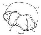
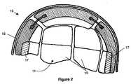
図1および図2の安全ヘルメット10は、開口部11を介して外側に通じるキャビティを画成しており、キャビティの内側に頭部を適合するようになっている。ヘルメット10は、単一部品で形成され、ノッチを有していない外側シェル12を備えている。シェル12の内側には、複数のダンピング要素13が付設されており、シェル12の内面の全体を実質的に覆っているダンピングライナー(damping liner)を形成している。ダンピング要素13を互いに結合するように結合手段を設けることができるが、このような結合手段は必須ではない。各ダンピング要素13は、他のダンピング要素13に連結されることなくシェルに付着させることができる。 The
ノッチによって理解されるべきことは、ヘルメットの厚さ全体にわたる(すなわち、発泡体ライナーの全厚さ、およびシェルの全厚さにわたる)局所的な細長い材料除去部が、ヘルメットのエッジに通じるように構成されることである。しかしながら、シェル12は、閉ざされた輪郭を有する局所的な通気開口部、すなわちヘルメットのエッジに通じていない局所的な通気開口部を有することができる。 What is to be understood by the notch is that local elongated material removal that spans the entire thickness of the helmet (ie, the entire thickness of the foam liner and the entire thickness of the shell) leads to the edge of the helmet. Is to be configured. However, the
ダンピング要素13は、発泡スチレン(PSE)、または、PSE若しくは興味深いダンピング特性に匹敵する経済的利益をもたらす他の実質的な硬質発泡体から作製されている。一方、シェル12は、例えば、ポリカーボネート、アクリロニトリルブタジエンスチレン(あるいはABS)、ポリスチレン、ポリエチレンテレフタレートグリコール(あるいはPETG)、またはポリ塩化ビニル(あるいはPVC)などの熱可塑性ポリマー材料といった、弾性変形可能な材料から作製されている。シェル12の材料は、シェル12が外部衝撃力に対して十分な抵抗力を示すと共に、材料の曲げ係数が1500〜4500MPaとなるように選択される。屈曲において必要とされる柔軟な変形能力のために、外側シェル12の厚さは、とりわけ弾性係数に応じて、例えば0.5〜3mmとなる。また、シェル12を形成する材料は、好ましくは10%を超える引張破壊伸び特性をもたらす。
使用時には、ダンピング要素13間の結合手段は、任意の方法で実現されることができ、例えば、ダンピング要素13間の相対移動を可能にするように構成されている。 In use, the coupling means between the
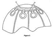
第1の解決法は、全てのダンピング要素13を互いに連結する単一の構造体14を使用することである。周囲に複数の側部、前部および後部ダンピング要素が角度を付けて配設されている頂部ダンピング要素によってダンピングライナーが形成されている場合、単一の構造体14は、例えば、クモの形状とすることができる。その頭は、頂部ダンピング要素に取り付けられ、各脚は、頂部ダンピング要素と周囲のダンピング要素との間の結合を行う。図3においては、頂部、側部、前部および後部ダンピング要素は、単一の構造体14に外側被覆することにより実現されている。他方、図5においては、単一の構造体14は、外側被覆されておらず、ダンピング要素13と外側シェル12の内面との間に閉じ込められている。 The first solution is to use a
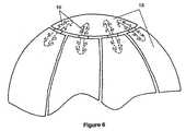
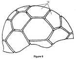
他の解決法は、2つのダンピング要素13の間の局所的な連結を個々に行う複数の個別連結部品を使用することである。周囲に複数の側部、前部および後部ダンピング要素が角度を付けて配設されている頂部ダンピング要素によってダンピングライナーが形成されている場合、各連結部品は、頂部ダンピング要素と周囲のダンピング要素との間の連結を行う。図4においては、各連結部品は、布地、またはVelcro(登録商標)タイプの自己グリップ材料から作製されたバンドを閉じることにより形成されたループ15の形状となっている。ループ15の一方の端部は、頂部ダンピング要素内に配設された通路開口部を貫通し、他方の端部は、これに結合された周囲のダンピング要素の通路開口部を貫通している。他方、図6においては、各連結部品は、軸方向にオフセットされた2つの部分の間のインサート16によって形成されている。各部品は、頂部ダンピング要素または周囲のダンピング要素と協働するように構成され、この目的のために、モミの木の形状の複数の非戻りタブ(anti-return tab)を有している。 Another solution is to use a plurality of individual connecting parts that make local connections between the two
開口部11の周囲に沿って配設されたダンピング要素13のシェル12の方を向く面全体は、シェル12の内面に位置付けられ、開口部の周囲を画定し、シェルに完全に接触する支持ベルトを形成している。このため、ユーザの頭部がヘルメットのキャビティ内の適切な位置にある場合、支持ベルトを形成する各ダンピング要素13のシェル12の方を向く面全体は、シェル12の内面に完全に接触する。開口部11の周囲の全体を画定する支持ベルトを形成して開口部11の周囲に沿って空きスペースが設けられることを回避するために、開口部11の周囲に配設されたダンピング要素13は、並んで位置付けられ、または数ミリメートルのごくわずかな距離で配置されることができる。支持ベルトは、開口部11の輪郭を内側に画成するリング形状になっている。外側では、支持ベルトは、シェル12の内面に完全に接触し、シェル12と、ベルトを構成するダンピング要素13との間にデッドボリュームが配置されないことを保証し、最適な保護を提供する。 The entire surface facing the
シェル12の形状、大きさおよび厚さと、支持ベルトを構成するダンピング要素13の厚さは、(開口部11の周囲を画成する)支持ベルトの内側寸法が頭部のために予定されている接触領域内において頭部の所望の周長に完全に適合するように、選択される。このことにより、ヘルメットは以下のように構成される。すなわち、ヘルメットのキャビティ内におけるヘッドの位置付けが、支持ベルトの変形を引き起こし、その結果としてシェルの弾性的な屈曲変形を生じ、(ヘルメットのキャビティ内に頭部が位置付けられる前の)元の構造に戻ろうとするシェルの柔軟な付勢力によって、支持ベルトに沿って実質的に均一に、頭部に対する支持ベルトの永続的な締め付けを生じさせる。 The shape, size and thickness of the
ダンピング要素13の間の結合手段がどんなものであっても、シェル12の内面へのダンピングライナーの固定は、シェルへライナーの少なくとも1つのダンピング要素13を取り付けることによって行われ得る。このような取付手段は、シェル12と、取り付けられたダンピング要素13との間のわずかなスライドを可能にするように構成され得る。このダンピング要素13とシェル12との間のわずかなスライドと、ダンピング要素13間の移動とは、潜在的に不快な音を発生させ得るが、このような不快な音には、シェルの内面および/またはダンピング要素をライトフェルト(light felt)、スプレー、またはシリコンタイプなどのコーティングで覆うことによって対抗することができる。 Whatever the coupling means between the damping
周囲に複数の側部、前部および後部ダンピング要素が角度を付けて配設されている頂部ダンピング要素によってダンピングライナーが形成されている場合、第1の解決法は、頂部ダンピング要素のシェル12の内面への固定を行う取付手段を使用することである。第2の解決法においては、ヘルメット10は、支持ベルトを構成するダンピング要素をシェル12に一体的に取り付けるための手段を有しており、これにより、支持ベルトはシェル12の内面に完全に固定されている。そして、その手段は、シェル12と、取り付けられたダンピング要素との間のわずかな量のスライドを可能にするために、支持ベルトを構成するダンピング要素をシェル12に一体的に取り付けるために設けられていることが好ましい。この特徴は、Velcro(登録商標)の自己グリップバンドタイプまたは協働ループ/フックタイプの固定手段を使用することによって得ることができ、頭部の形に対するダンピング要素のより良い適合という利点をもたらす。 When the damping liner is formed by a top damping element having a plurality of side, front and rear damping elements disposed at an angle around the first damping solution, the first solution is that of the
支持ベルトと頭部との間の接触のレベルの快適さを改善する他の実施の形態においては、シェル12に取り付けられた支持ベルトを構成するダンピング要素の面の反対側の面に、圧縮要素17が配設され得る。このような圧縮要素17は、支持ベルトの周長の全体または一部を覆うことができ、強固な軟質発砲体、例えばエチレン酢酸ビニルから作製され、支持ベルトのダンピング要素が製造される際に付設される、または設けられる。このような圧縮要素17は、補完ベルトを作り出す機能を有し、圧縮要素17の変形によって、所望の頭部周長のために提供されたヘルメットの内側に、より大きな周長を有する頭部が位置付けられることを可能にする。 In another embodiment that improves the comfort of the level of contact between the support belt and the head, the compression element is placed on the surface opposite the surface of the damping element that constitutes the support belt attached to the
さらに、ダンピングライナーの全体または一部にわたって、ダンピング要素13の間のギャップを充填する充填要素が配設され得る。このような充填要素は、適度に強固な柔軟材料、例えばエチレン酢酸ビニルから作製され得る。 Furthermore, a filling element that fills the gap between the damping
非限定的な実施の形態によれば、ダンピング要素13の間に配設された充填要素は、分離要素18によって形成され得る。図11に示したように、このような分離要素18は、各ダンピング要素13の間の残部に最小スペースを永続的に維持することを目的として概略的なV字形状を採用する柔軟性コネクタによって形成され得る。外力の影響による柔軟性コネクタの変形によって、この最小スペースは、一時的に減少して、その後、外力がなくなると、元の残部構造にコネクタの柔軟的な回復によってその元のサイズに戻ることができる。この実施の形態は、圧縮要素17が無い場合に特に有利である。 According to a non-limiting embodiment, the filling element disposed between the damping
シェル12とダンピング要素13との間のスライドを作り出すことに加えて、分離要素18は、シェル12の内面に対してダンピング要素13を配置する効果が、とりわけヘルメットが使用されていない間、一定に維持されて、要素13の動きを排除することを保証するという第1の利点をもたらす。それらは、さらに、スライドを助長することにより、シェルによっておよび分割されたライナーによって形成された組立体の変形を容易にする。最後に、それらは、要素13の間の接触および要素とシェル12との間の接触によって引き起こされる不快な音やこすれる音を排除することができる。分離要素18は、材料(例えば、PEまたはPP)の熱成型または射出成型によって得ることができる。 In addition to creating a slide between the
また、ヘルメット10は、各々が支持ベルトに属している2つの対向するダンピング要素に端部が連結されたあごひもを有することができる。 The
図7乃至図10の目的は、ダンピングライナーのダンピング要素13の可能性のある異なる形状の変形例を示すことである。図10においては、頂部ダンピング要素は、頂部ダンピング要素の周囲に配設された複数の側部、前部および後部ダンピング要素に連結されている。図9は、図10の変形例であって、ここでは、周囲のダンピング要素が、キャビティの底部の方向にオフセットされた2つの独立した要素にさらに分割されている。一方、図7および図8は、ダンピング要素13がシェル12の内面全体にわたって六角形状で均一に分配され、大きい分配密度を有するライナーと、これより小さい分配密度を有するライナーを示している。 The purpose of FIGS. 7 to 10 is to show possible different shaped variants of the damping
上述したヘルメットの他の実施の形態の全ては、ヘルメット内の向上した通気品質という利点をもたらす。ユーザの頭部から発生する熱は、主に、頭蓋骨の周囲における放射である。要素13の間のスリットまたはギャップは、熱および水分の効率的な除去を可能にする空気流網を形成する。この効果は、シェル12に、外側に開口してユーザの動きにより引き起こされる可変の通気の形成を容易にする穴が設けられた場合に、増大され得る。 All of the other embodiments of the helmet described above provide the advantage of improved ventilation quality within the helmet. The heat generated from the user's head is mainly radiation around the skull. The slits or gaps between the
最後に、安全性に関して、側部ダンピング要素13が浮遊している上述した実施の形態は、接線方向の力成分の場合に頭部とシェルとの間のスライドおよび枢動によってエネルギの一部を吸収することができる。この数十ミリメートルの移動は、ストレスのピークを吸収して、脳へのダメージのしきい値以下にとどまらせることを可能にする点で重要である。ストレスがより大きい場合には、頭部とヘルメットとの間の支持ベルトの平面内におけるスライドが、衝撃波を弱めることを可能にする。このことは、支持ベルトの周長の変形が無いことにより可能となる。 Finally, with respect to safety, the above-described embodiment in which the
好適な他の実施の形態においては、頂部ダンパー要素13とシェル12とを取り付ける手段は、ヒューズ要素として作用することができ、2つの要素を互いから少なくとも部分的に分離させることができ、ライナーに対してシェルのより大きな回転を可能にし、伝達される力をほとんどゼロにする。このような取付手段は、接着剤、例えばホットメルト接着剤のタイプ、若しくは磁石で、またはVelcro(登録商標)タイプの自己グリップ材料で、実現され得る。シェル12は、ユーザのあごの下のあごひも、またはその同等物が全体の一体性を保証するために、分離することはできない。 In another preferred embodiment, the means for attaching the
Claims (10)
Translated fromJapanese単一部品の外側シェル(12)と、
シェル(12)の内側に付設された複数のダンピング要素(13)と、を備え、
ダンピング要素(13)は、硬質発泡体によって形成され、シェル(12)は、弾性変形可能な材料から作製され、
開口部(11)の周囲に配設されたダンピング要素(13)のシェル(12)の方を向く面全体が、シェル(12)の内面に位置付けられて内側支持ベルトを形成し、
キャビティ内に前記頭部が位置付けられた場合、当該頭部がダンピング要素(13)を介してシェル(12)を押圧し、これにより支持ベルトがシェル(12)と完全に接触してシェル(12)を当該頭部の形に応じて弾性変形させ、弾性変形したシェル(12)の付勢力によって支持ベルトに沿って均一に、頭部に対する支持ベルトの永続的な締め付けを生じさせるように構成されていることを特徴とするヘルメット。In a safety helmet (10) defining a cavity that leads to the outside through an opening (11) and fitsa headhaving adesired circumference ,
A single part outer shell (12);
A plurality of damping elements (13) attached to the inside of the shell (12),
The damping element (13) is formed by a rigid foam, the shell (12) is made of an elastically deformable material,
Entire surface facing the shell (12) of disposed a damping element around (13) of the opening (11), theinner side support belt formedis positioned on the inner surface of the shell (12),
When the head is positioned in the cavity, thehead presses the shell (12) via the damping element (13), so that the support belt comes into full contact with the shell (12) and the shell (12 ) and it is elastically deformed according to the shape of the head, configuredevenly onealong the support beltby the urging force of the shell (12) which is elastically deformed, to produce a permanent fastening of the support belt with respect to the head Helmet characterized by being.
Applications Claiming Priority (3)
| Application Number | Priority Date | Filing Date | Title |
|---|---|---|---|
| FR09/00674 | 2009-02-13 | ||
| FR0900674AFR2942111B1 (en) | 2009-02-13 | 2009-02-13 | DEFORMABLE PROTECTION HELMET |
| PCT/FR2010/000108WO2010092254A1 (en) | 2009-02-13 | 2010-02-11 | Deformable safety helmet |
Publications (2)
| Publication Number | Publication Date |
|---|---|
| JP2012518097A JP2012518097A (en) | 2012-08-09 |
| JP5693472B2true JP5693472B2 (en) | 2015-04-01 |
Family
ID=41066142
Family Applications (1)
| Application Number | Title | Priority Date | Filing Date |
|---|---|---|---|
| JP2011549621AExpired - Fee RelatedJP5693472B2 (en) | 2009-02-13 | 2010-02-11 | Deformable safety helmet |
Country Status (7)
| Country | Link |
|---|---|
| US (1) | US8850622B2 (en) |
| EP (1) | EP2395865B1 (en) |
| JP (1) | JP5693472B2 (en) |
| CA (1) | CA2752516C (en) |
| DK (1) | DK2395865T3 (en) |
| FR (1) | FR2942111B1 (en) |
| WO (1) | WO2010092254A1 (en) |
Families Citing this family (85)
| Publication number | Priority date | Publication date | Assignee | Title |
|---|---|---|---|---|
| US9289024B2 (en) | 2007-04-16 | 2016-03-22 | Riddell, Inc. | Protective sports helmet |
| EP2347665A1 (en)* | 2010-01-22 | 2011-07-27 | Nederlandse Organisatie voor toegepast -natuurwetenschappelijk onderzoek TNO | Helmet element |
| US8588806B2 (en) | 2010-02-26 | 2013-11-19 | Thl Holding Company, Llc | Wireless device and methods for use in a paging network |
| US9943746B2 (en)* | 2010-02-26 | 2018-04-17 | The Holding Company, Llc | Protective headgear with impact diffusion |
| NL2005798C2 (en)* | 2010-12-01 | 2012-06-04 | Headies B V | Safety helmet with flexible impact core. |
| US10952484B2 (en) | 2016-09-01 | 2021-03-23 | Adrienne Yeung | Conformal protective head wear |
| US12268264B2 (en) | 2010-12-31 | 2025-04-08 | Adrienne Yeung | Conformal protective head wear |
| USD681281S1 (en) | 2011-05-02 | 2013-04-30 | Riddell, Inc. | Protective sports helmet |
| USD838922S1 (en) | 2011-05-02 | 2019-01-22 | Riddell, Inc. | Football helmet |
| US20140090155A1 (en)* | 2011-05-05 | 2014-04-03 | James Michael Johnston | Systems and methods for attenuating rotational acceleration of the head |
| US9032558B2 (en) | 2011-05-23 | 2015-05-19 | Lionhead Helmet Intellectual Properties, Lp | Helmet system |
| US9763488B2 (en) | 2011-09-09 | 2017-09-19 | Riddell, Inc. | Protective sports helmet |
| WO2013123113A1 (en)* | 2012-02-16 | 2013-08-22 | Bonin Walter | Personal impact protection device |
| US20150223546A1 (en)* | 2012-09-14 | 2015-08-13 | Yochanan Cohen | Protective Helmets |
| US9572390B1 (en)* | 2012-10-05 | 2017-02-21 | Elwood J. B. Simpson | Football helmet having improved impact absorption |
| US9603408B2 (en)* | 2012-10-05 | 2017-03-28 | Elwood J. B. Simpson | Football helmet having improved impact absorption |
| US10159296B2 (en) | 2013-01-18 | 2018-12-25 | Riddell, Inc. | System and method for custom forming a protective helmet for a customer's head |
| US9314063B2 (en) | 2013-02-12 | 2016-04-19 | Riddell, Inc. | Football helmet with impact attenuation system |
| SE1351032A1 (en)* | 2013-04-19 | 2014-10-20 | Mips Ab | Connecting arrangements and helmets including such connecting arrangements |
| FR3009167B1 (en)* | 2013-08-05 | 2016-01-01 | Salomon Sas | HELMET |
| US10645982B2 (en)* | 2013-10-28 | 2020-05-12 | Robert T. Bayer | Protective athletic helmet to reduce linear and rotational brain acceleration |
| US20170367428A1 (en)* | 2013-10-28 | 2017-12-28 | Robert T. Bayer | Protective Athletic Helmet to Reduce Linear and Rotational Brain Acceleration |
| US10362829B2 (en) | 2013-12-06 | 2019-07-30 | Bell Sports, Inc. | Multi-layer helmet and method for making the same |
| CA3186442A1 (en) | 2013-12-19 | 2015-06-25 | Bauer Hockey Ltd. | Helmet for impact protection |
| US9693594B1 (en)* | 2014-02-18 | 2017-07-04 | Harvest Moon Inventions, LLC | Protective headgear |
| US10993496B2 (en) | 2014-02-21 | 2021-05-04 | Matscitechno Licensing Company | Helmet padding system |
| US20180235303A1 (en)* | 2014-02-21 | 2018-08-23 | Matscitechno Licensing Company | Helmet padding system |
| US11744312B2 (en) | 2014-02-21 | 2023-09-05 | Matscitechno Licensing Company | Helmet padding system |
| US11659882B2 (en) | 2014-02-21 | 2023-05-30 | Matscitechno Licensing Company | Helmet padding system |
| US11730222B2 (en) | 2014-02-21 | 2023-08-22 | Matscitechno Licensing Company | Helmet padding system |
| US11253771B2 (en)* | 2014-02-21 | 2022-02-22 | Matscitechno Licensing Company | Helmet padding system |
| JP6345444B2 (en)* | 2014-03-04 | 2018-06-20 | 一般財団法人日本自動車研究所 | Head protection |
| JP6413303B2 (en)* | 2014-04-02 | 2018-10-31 | 凸版印刷株式会社 | Composite food container |
| CN106470565B (en)* | 2014-07-03 | 2019-06-21 | 贝尔运动股份有限公司 | flexible spring helmet |
| GB2530309A (en) | 2014-09-19 | 2016-03-23 | Strategic Sports Ltd | A triple layered compressible liner for impact protection |
| US10721987B2 (en) | 2014-10-28 | 2020-07-28 | Bell Sports, Inc. | Protective helmet |
| US9943129B2 (en) | 2015-04-06 | 2018-04-17 | Cascade Maverik Lacrosse, Llc | Protective headgear |
| FR3035778B1 (en)* | 2015-05-06 | 2017-05-12 | Salomon Sas | SPORT HELMET |
| GB2540198B (en)* | 2015-07-09 | 2020-12-09 | Jsp Ltd | Protective headgear |
| US9961952B2 (en) | 2015-08-17 | 2018-05-08 | Bauer Hockey, Llc | Helmet for impact protection |
| US10376010B2 (en) | 2015-11-04 | 2019-08-13 | Bell Sports, Inc. | Shock absorbing helmet |
| US12250980B2 (en) | 2015-12-18 | 2025-03-18 | Matscitechno Licensing Company | Apparatuses, systems and methods for equipment for protecting the human body by absorbing and dissipating forces imparted to the body |
| US11864599B2 (en) | 2015-12-18 | 2024-01-09 | Matscitechno Licensing Company | Apparatuses, systems and methods for equipment for protecting the human body by absorbing and dissipating forces imparted to the body |
| DE202016100235U1 (en) | 2016-01-19 | 2017-04-20 | Rockwell Gmbh | helmet |
| WO2018017867A1 (en) | 2016-07-20 | 2018-01-25 | Riddell, Inc. | System and methods for designing and manufacturing a bespoke protective sports helmet |
| US10595577B1 (en)* | 2016-10-17 | 2020-03-24 | Terry Leonard Lewis | Lewis helmet |
| US11229255B2 (en)* | 2016-11-08 | 2022-01-25 | JMH Consulting Group, LLC | Helmet |
| DE102017108038A1 (en) | 2017-04-13 | 2018-10-18 | Rockwell Gmbh | Adjustable damping insert |
| US10542788B2 (en) | 2017-05-11 | 2020-01-28 | Safer Sports, LLC | Football helmet having three energy absorbing layers |
| GB201708094D0 (en) | 2017-05-19 | 2017-07-05 | Mips Ab | Helmet |
| US20180338558A1 (en)* | 2017-05-24 | 2018-11-29 | David Christopher Reynolds | Helmet impact absorption system |
| USD850013S1 (en) | 2017-07-20 | 2019-05-28 | Riddell, Inc. | Internal padding assembly of a protective sports helmet |
| USD850012S1 (en) | 2017-07-20 | 2019-05-28 | Riddell, Inc. | Internal padding assembly of a protective sports helmet |
| USD850011S1 (en) | 2017-07-20 | 2019-05-28 | Riddell, Inc. | Internal padding assembly of a protective sports helmet |
| US10201208B1 (en)* | 2017-07-26 | 2019-02-12 | Ronnie Z. Bochner | Foldable helmet |
| WO2019023224A1 (en)* | 2017-07-27 | 2019-01-31 | Counter, Inc. | Protective sports headgear |
| EP4581972A1 (en) | 2017-10-19 | 2025-07-09 | Mips Ab | Helmet |
| WO2020037279A1 (en) | 2018-08-16 | 2020-02-20 | Riddell, Inc. | System and method for designing and manufacturing a protective helmet |
| WO2020056416A1 (en)* | 2018-09-14 | 2020-03-19 | Beckman Steven Benjamin | Baseball helmet and related methods |
| USD917101S1 (en) | 2018-09-26 | 2021-04-20 | Dana Ratliff | Football helmet |
| US10306944B1 (en) | 2018-10-19 | 2019-06-04 | Dana Ratliff | Modular helmet apparatus and system |
| US10426212B1 (en)* | 2018-10-19 | 2019-10-01 | Dana Ratliff | Modular football helmet apparatus and system |
| CA3169309A1 (en) | 2018-11-21 | 2020-05-28 | Riddell, Inc. | Protective recreational sports helmet with components additively manufactured to manage impact forces |
| USD927084S1 (en) | 2018-11-22 | 2021-08-03 | Riddell, Inc. | Pad member of an internal padding assembly of a protective sports helmet |
| CA3133385A1 (en)* | 2019-03-14 | 2020-09-17 | Socovar L.P. | Helmet with padding arrangement |
| US11849793B2 (en)* | 2019-03-29 | 2023-12-26 | Bell Sports, Inc. | Flexible slip plane for helmet energy management liner |
| USD927073S1 (en) | 2019-04-16 | 2021-08-03 | Safer Sports, LLC | Football helmet |
| IT201900009369A1 (en) | 2019-06-18 | 2020-12-18 | Alpinestars Res Spa | Protective helmet |
| FR3100692B1 (en)* | 2019-09-13 | 2021-09-24 | Roof Int | Protective helmet and method of mounting a cushioning pad for a helmet |
| US10869520B1 (en) | 2019-11-07 | 2020-12-22 | Lionhead Helmet Intellectual Properties, Lp | Helmet |
| US20210153592A1 (en) | 2019-11-22 | 2021-05-27 | Safer Sports, LLC DBA Light Helmets | Soft shell helmet |
| USD935106S1 (en) | 2019-11-22 | 2021-11-02 | Safer Sports, LLC | Helmet |
| IT202000001117A1 (en)* | 2020-01-22 | 2021-07-22 | Mango Sport System S R L | PROTECTIVE HELMET |
| US11540577B2 (en) | 2020-03-12 | 2023-01-03 | Matscitechno Licensing Company | Helmet system |
| US11540578B2 (en) | 2020-03-12 | 2023-01-03 | Matscitechno Licensing Company | Helmet system |
| US10905187B1 (en) | 2020-03-30 | 2021-02-02 | Gwenventions, Llc | Collapsible helmet |
| GB202107484D0 (en)* | 2021-05-26 | 2021-07-07 | Mips Ab | Shell, kit, helmet and methods of manufacture of a shell |
| US11832675B2 (en)* | 2021-08-20 | 2023-12-05 | Tenacious Holdings, Inc. | Insert for a hat |
| US20250275600A1 (en)* | 2021-11-01 | 2025-09-04 | Mips Ab | Connector and apparatus |
| US11547166B1 (en) | 2022-02-11 | 2023-01-10 | Lionhead Helmet Intellectual Properties, Lp | Helmet |
| JP7216454B1 (en) | 2022-02-14 | 2023-02-01 | 株式会社シゲマツ | hat |
| US11641904B1 (en) | 2022-11-09 | 2023-05-09 | Lionhead Helmet Intellectual Properties, Lp | Helmet |
| JP7664659B1 (en) | 2024-01-09 | 2025-04-18 | 株式会社谷沢製作所 | helmet |
| JP7599250B1 (en) | 2024-01-09 | 2024-12-13 | 株式会社谷沢製作所 | helmet |
| US12121095B1 (en) | 2024-04-24 | 2024-10-22 | Lionhead Helmet Intellectual Properties, Lp | Helmet |
Family Cites Families (36)
| Publication number | Priority date | Publication date | Assignee | Title |
|---|---|---|---|---|
| US532567A (en)* | 1895-01-15 | Head-protector | ||
| US2706294A (en)* | 1952-01-15 | 1955-04-19 | Goodyear Tire & Rubber | Protective headgear |
| US2969547A (en)* | 1958-12-17 | 1961-01-31 | Edward R Dye | Protective head covering |
| US2983923A (en)* | 1959-01-20 | 1961-05-16 | Leonard P Frieder | Rigging for protective helmet |
| US3153792A (en)* | 1963-07-09 | 1964-10-27 | Michael T Marietta | Two part detachable liner for safety helmets |
| US3241154A (en)* | 1963-12-03 | 1966-03-22 | Leonard P Frieder | Safety helmets |
| US3329968A (en)* | 1965-04-20 | 1967-07-11 | Donald W Gordon | Athletic helmet with floating adjustable headband |
| US3486169A (en)* | 1968-01-26 | 1969-12-30 | Automatic Sprinkler Corp | Helmet combination suspension |
| US3465363A (en)* | 1968-07-01 | 1969-09-09 | American Safety Equip | Safety helmet sizing band |
| US3787894A (en)* | 1972-10-12 | 1974-01-29 | J Goodman | Easily adjustable protective head gear |
| JPS5435781Y2 (en)* | 1973-04-06 | 1979-10-30 | ||
| US3994020A (en)* | 1975-06-05 | 1976-11-30 | The Kendall Company | Protective helmet with liner means |
| JPS5313423U (en)* | 1976-07-13 | 1978-02-03 | ||
| CH657760A5 (en)* | 1984-06-18 | 1986-09-30 | Battelle Memorial Institute | IMPACT PROTECTIVE HELMET AND MANUFACTURING METHOD THEREOF. |
| DE8804821U1 (en)* | 1988-04-13 | 1988-06-01 | Peter Küpper "Codeba" GmbH & Co, 5600 Wuppertal | Headgear such as helmet, cap, hat or similar, especially for riders |
| JPH0638093Y2 (en)* | 1991-02-26 | 1994-10-05 | 昭栄化工株式会社 | Helmet cap |
| US5337420A (en)* | 1992-11-03 | 1994-08-16 | Haysom Elbert M | Method and apparatus for mounting and locating a helmet comfortably on the head of a person, and combination resulting therefrom |
| US5511250A (en)* | 1995-01-26 | 1996-04-30 | A-Star Sports Group, Inc. | Adjustable protective helmet |
| EP1066765B1 (en)* | 1995-10-30 | 2005-06-15 | Shoei Co., Ltd. | Safety helmet and a head protector therefor |
| US5575017A (en)* | 1996-01-02 | 1996-11-19 | Rawlings Sporting Goods Company, Inc. | Adjustable baseball batter's helmet |
| US5694649A (en)* | 1996-01-02 | 1997-12-09 | Rawlings Sporting Goods Company, Inc. | Adjustable baseball batter's and catcher's helmet with mask |
| JP2853850B2 (en)* | 1996-03-01 | 1999-02-03 | 株式会社アライヘルメット | Helmet interior pad and interior pad |
| US5815847A (en)* | 1997-06-23 | 1998-10-06 | Ampac Enterprises, Inc. | One size fits all baseball batter's helmet |
| US6128786A (en)* | 1997-10-16 | 2000-10-10 | Hos Development Corporation | One-size-fits-all helmet |
| US6085357A (en)* | 1998-04-09 | 2000-07-11 | Troxel Cycling & Fitness, Llc | Headgear fitting and accessory system |
| US6317895B1 (en)* | 1999-02-26 | 2001-11-20 | Mine Safety Appliances Company | Safety helmet assembly |
| DE10029374A1 (en)* | 1999-06-23 | 2000-12-28 | Manfred Busen | Riding hat, comprises a plastic shell and a ring shaped damping member with a net or tissue material on its surface. |
| US6240571B1 (en)* | 1999-11-09 | 2001-06-05 | Riddell, Inc. | Protective helmet with adjustable sizes |
| AUPR071200A0 (en)* | 2000-10-12 | 2000-11-09 | Bostock Developments Pty Ltd | Safety headgear |
| US6665884B1 (en)* | 2002-05-31 | 2003-12-23 | Adams Usa | Helmet with self-adjusting padding |
| JP4059729B2 (en)* | 2002-08-09 | 2008-03-12 | 株式会社Shoei | Head protector for safety helmet |
| IL152006A0 (en)* | 2002-09-30 | 2003-07-31 | Rabintex Ind Ltd | Shell for ballistic helmet |
| US6865752B2 (en)* | 2002-12-23 | 2005-03-15 | Wilson Sporting Goods Co. | Adjustable sports helmet |
| FR2904197B1 (en)* | 2006-07-26 | 2008-12-26 | Salomon Sa | HEAD PROTECTION ASSEMBLY |
| FR2905235B1 (en)* | 2006-08-29 | 2009-03-13 | Salomon Sa | PROTECTIVE HELMET AND METHOD OF MANUFACTURING THE SAME |
| US7987525B2 (en)* | 2007-04-13 | 2011-08-02 | Klim | Helmet |
- 2009
- 2009-02-13FRFR0900674Apatent/FR2942111B1/ennot_activeExpired - Fee Related
- 2010
- 2010-02-11EPEP10707090Apatent/EP2395865B1/ennot_activeNot-in-force
- 2010-02-11DKDK10707090.6Tpatent/DK2395865T3/enactive
- 2010-02-11WOPCT/FR2010/000108patent/WO2010092254A1/enactiveApplication Filing
- 2010-02-11USUS13/201,381patent/US8850622B2/ennot_activeExpired - Fee Related
- 2010-02-11JPJP2011549621Apatent/JP5693472B2/ennot_activeExpired - Fee Related
- 2010-02-11CACA2752516Apatent/CA2752516C/ennot_activeExpired - Fee Related
Also Published As
| Publication number | Publication date |
|---|---|
| US8850622B2 (en) | 2014-10-07 |
| FR2942111B1 (en) | 2011-02-25 |
| FR2942111A1 (en) | 2010-08-20 |
| WO2010092254A1 (en) | 2010-08-19 |
| DK2395865T3 (en) | 2013-07-01 |
| EP2395865B1 (en) | 2013-04-03 |
| EP2395865A1 (en) | 2011-12-21 |
| US20120047635A1 (en) | 2012-03-01 |
| CA2752516A1 (en) | 2010-08-19 |
| CA2752516C (en) | 2017-06-27 |
| JP2012518097A (en) | 2012-08-09 |
Similar Documents
| Publication | Publication Date | Title |
|---|---|---|
| JP5693472B2 (en) | Deformable safety helmet | |
| US10561181B2 (en) | Face mask having a flexible skeleton and a flexible skeleton for a face mask | |
| US6427253B1 (en) | Protective headgear comprising a headband and a semi-rigid support to protect a back region of a user's head | |
| US8191179B2 (en) | Hockey helmet with an outer shell made of two different materials | |
| US9538799B2 (en) | Watertight cap | |
| US20160021966A1 (en) | Lacrosse helmet | |
| US20090241240A1 (en) | Cap with ventilation channels | |
| JP2016536473A (en) | System and method for connecting helmet components and liners | |
| US8561216B2 (en) | Helmet | |
| US11291264B2 (en) | Football helmet shell | |
| US20060123526A1 (en) | Inner layer of cover for bulletproof helmet | |
| EP2523573A1 (en) | Helmet comprising surface reinforcing component with embedded anchors | |
| CA2965321C (en) | Football helmet with cheek supports | |
| US20050193477A1 (en) | Protective headgear | |
| AU2021295599B2 (en) | Helmet | |
| US20170120134A1 (en) | Lacrosse helmet | |
| US20050081279A1 (en) | Elastic headwear | |
| US20230180878A1 (en) | Helmet fit system and methods | |
| CA2783078C (en) | Ear protector for a hockey or lacrosse helmet | |
| US20080256682A1 (en) | Headwear having attached panels | |
| JP2012072540A (en) | Protective helmet | |
| AU2021297261A1 (en) | Impact protection system | |
| TW202502227A (en) | Protective helmet | |
| EP2759218B1 (en) | Helmet | |
| EP3549468B1 (en) | Helmet with floating brow band |
Legal Events
| Date | Code | Title | Description |
|---|---|---|---|
| A621 | Written request for application examination | Free format text:JAPANESE INTERMEDIATE CODE: A621 Effective date:20130108 | |
| A977 | Report on retrieval | Free format text:JAPANESE INTERMEDIATE CODE: A971007 Effective date:20140130 | |
| A131 | Notification of reasons for refusal | Free format text:JAPANESE INTERMEDIATE CODE: A131 Effective date:20140204 | |
| A601 | Written request for extension of time | Free format text:JAPANESE INTERMEDIATE CODE: A601 Effective date:20140502 | |
| A602 | Written permission of extension of time | Free format text:JAPANESE INTERMEDIATE CODE: A602 Effective date:20140513 | |
| A521 | Request for written amendment filed | Free format text:JAPANESE INTERMEDIATE CODE: A523 Effective date:20140604 | |
| TRDD | Decision of grant or rejection written | ||
| A01 | Written decision to grant a patent or to grant a registration (utility model) | Free format text:JAPANESE INTERMEDIATE CODE: A01 Effective date:20150106 | |
| A61 | First payment of annual fees (during grant procedure) | Free format text:JAPANESE INTERMEDIATE CODE: A61 Effective date:20150203 | |
| R150 | Certificate of patent or registration of utility model | Ref document number:5693472 Country of ref document:JP Free format text:JAPANESE INTERMEDIATE CODE: R150 | |
| LAPS | Cancellation because of no payment of annual fees |