JP5687197B2 - Method and apparatus for coupling a prosthesis to a spinal segment - Google Patents
Method and apparatus for coupling a prosthesis to a spinal segmentDownload PDFInfo
- Publication number
- JP5687197B2 JP5687197B2JP2011526200AJP2011526200AJP5687197B2JP 5687197 B2JP5687197 B2JP 5687197B2JP 2011526200 AJP2011526200 AJP 2011526200AJP 2011526200 AJP2011526200 AJP 2011526200AJP 5687197 B2JP5687197 B2JP 5687197B2
- Authority
- JP
- Japan
- Prior art keywords
- item
- patient
- compliance element
- tool
- lower back
- Prior art date
- Legal status (The legal status is an assumption and is not a legal conclusion. Google has not performed a legal analysis and makes no representation as to the accuracy of the status listed.)
- Active
Links
Images


Classifications
- A—HUMAN NECESSITIES
- A61—MEDICAL OR VETERINARY SCIENCE; HYGIENE
- A61B—DIAGNOSIS; SURGERY; IDENTIFICATION
- A61B17/00—Surgical instruments, devices or methods
- A61B17/56—Surgical instruments or methods for treatment of bones or joints; Devices specially adapted therefor
- A61B17/58—Surgical instruments or methods for treatment of bones or joints; Devices specially adapted therefor for osteosynthesis, e.g. bone plates, screws or setting implements
- A61B17/68—Internal fixation devices, including fasteners and spinal fixators, even if a part thereof projects from the skin
- A61B17/70—Spinal positioners or stabilisers, e.g. stabilisers comprising fluid filler in an implant
- A61B17/7062—Devices acting on, attached to, or simulating the effect of, vertebral processes, vertebral facets or ribs ; Tools for such devices
- A61B17/7067—Devices bearing against one or more spinous processes and also attached to another part of the spine; Tools therefor
- A—HUMAN NECESSITIES
- A61—MEDICAL OR VETERINARY SCIENCE; HYGIENE
- A61B—DIAGNOSIS; SURGERY; IDENTIFICATION
- A61B17/00—Surgical instruments, devices or methods
- A61B17/56—Surgical instruments or methods for treatment of bones or joints; Devices specially adapted therefor
- A61B17/58—Surgical instruments or methods for treatment of bones or joints; Devices specially adapted therefor for osteosynthesis, e.g. bone plates, screws or setting implements
- A61B17/68—Internal fixation devices, including fasteners and spinal fixators, even if a part thereof projects from the skin
- A61B17/70—Spinal positioners or stabilisers, e.g. stabilisers comprising fluid filler in an implant
- A61B17/7062—Devices acting on, attached to, or simulating the effect of, vertebral processes, vertebral facets or ribs ; Tools for such devices
- A—HUMAN NECESSITIES
- A61—MEDICAL OR VETERINARY SCIENCE; HYGIENE
- A61B—DIAGNOSIS; SURGERY; IDENTIFICATION
- A61B17/00—Surgical instruments, devices or methods
- A61B17/56—Surgical instruments or methods for treatment of bones or joints; Devices specially adapted therefor
- A61B17/58—Surgical instruments or methods for treatment of bones or joints; Devices specially adapted therefor for osteosynthesis, e.g. bone plates, screws or setting implements
- A61B17/68—Internal fixation devices, including fasteners and spinal fixators, even if a part thereof projects from the skin
- A61B17/70—Spinal positioners or stabilisers, e.g. stabilisers comprising fluid filler in an implant
- A61B17/7053—Spinal positioners or stabilisers, e.g. stabilisers comprising fluid filler in an implant with parts attached to bones or to each other by flexible wires, straps, sutures or cables
- A—HUMAN NECESSITIES
- A61—MEDICAL OR VETERINARY SCIENCE; HYGIENE
- A61B—DIAGNOSIS; SURGERY; IDENTIFICATION
- A61B17/00—Surgical instruments, devices or methods
- A61B17/56—Surgical instruments or methods for treatment of bones or joints; Devices specially adapted therefor
- A61B17/58—Surgical instruments or methods for treatment of bones or joints; Devices specially adapted therefor for osteosynthesis, e.g. bone plates, screws or setting implements
- A61B17/68—Internal fixation devices, including fasteners and spinal fixators, even if a part thereof projects from the skin
- A61B17/70—Spinal positioners or stabilisers, e.g. stabilisers comprising fluid filler in an implant
- A61B17/7055—Spinal positioners or stabilisers, e.g. stabilisers comprising fluid filler in an implant connected to sacrum, pelvis or skull
- A—HUMAN NECESSITIES
- A61—MEDICAL OR VETERINARY SCIENCE; HYGIENE
- A61B—DIAGNOSIS; SURGERY; IDENTIFICATION
- A61B17/00—Surgical instruments, devices or methods
- A61B2017/00681—Aspects not otherwise provided for
- A61B2017/00725—Calibration or performance testing
Landscapes
- Health & Medical Sciences (AREA)
- Orthopedic Medicine & Surgery (AREA)
- Life Sciences & Earth Sciences (AREA)
- Neurology (AREA)
- Surgery (AREA)
- Heart & Thoracic Surgery (AREA)
- Engineering & Computer Science (AREA)
- Biomedical Technology (AREA)
- Nuclear Medicine, Radiotherapy & Molecular Imaging (AREA)
- Medical Informatics (AREA)
- Molecular Biology (AREA)
- Animal Behavior & Ethology (AREA)
- General Health & Medical Sciences (AREA)
- Public Health (AREA)
- Veterinary Medicine (AREA)
- Neurosurgery (AREA)
- Prostheses (AREA)
- Surgical Instruments (AREA)
Description
Translated fromJapanese (1.発明の分野)
本発明は、概して、医療方法および装置に関する。より具体的には、本発明は、整形外科的な内部固定手術中に人工装具を脊髄分節に結合し、人工装具を調節するために使用される方法および装置に関する。これは、背部痛または他の脊髄症状を有する患者の治療を含むが、それに限定されない。(1. Field of the Invention)
The present invention generally relates to medical methods and apparatus. More specifically, the present invention relates to a method and apparatus used to couple a prosthesis to a spinal segment and adjust the prosthesis during orthopedic internal fixation surgery. This includes, but is not limited to, treating patients with back pain or other spinal symptoms.
慢性背下部痛の主な原因は、椎間板内破裂としても称される、椎間板起因の疼痛である。椎間板起因の疼痛を罹患する患者は、若年であるか、さもなければ、背部に局限した疼痛を呈する健康な個人である傾向がある。椎間板起因の疼痛は、通常、脊椎のL4−L5またはL5−S1の接合部に位置する椎間板で生じる。疼痛は、患者が腰椎を曲げさせた時に(すなわち、座位または前屈によって)悪化し、腰椎を伸展させた時に(すなわち、立位または後屈によって)緩和する傾向がある。曲げおよび伸展は、腰部の機械的荷重パターンを変更することで公知である。腰部が伸展状態にある時に、腰部によって負担される軸荷重は、椎間板および面関節によって共有される(荷重の約30%は、面関節によって負担される)。曲げにおいては、分節荷重は、椎間板によってほぼ完全に負担される。さらに、核は、後方に移動し、輪(神経支配されている)の後方部分上の荷重を変化させ、その線維が引張力およびせん断力を受ける可能性が高い。次いで、分節曲げは、椎間板によって負担される両方の荷重を増大させ、それらは、より疼痛を伴う方法で負担させられる。椎間板起因の疼痛は、比較的機能障害になる可能性があり、一部の患者では、労働および生活を満喫する能力に影響を及ぼす可能性がある。 The main cause of chronic lower back pain is intervertebral disc pain, also referred to as intradiscal rupture. Patients with intervertebral disc pain tend to be younger or otherwise healthy individuals with localized pain in the back. Intervertebral disc pain usually occurs in the intervertebral disc located at the L4-L5 or L5-S1 junction of the spine. Pain tends to worsen when the patient flexes the lumbar spine (ie, due to sitting or forward bending) and relieves when the lumbar spine extends (ie, due to standing or backward bending). Bending and stretching are known by changing the mechanical load pattern of the waist. When the lumbar part is in the extended state, the axial load borne by the lumbar part is shared by the intervertebral disc and the facet joint (about 30% of the load is carried by the facet joint). In bending, the segmental load is almost entirely borne by the intervertebral disc. In addition, the nucleus moves posteriorly and changes the load on the posterior part of the annulus (innervated), and its fibers are likely to undergo tensile and shear forces. Segmental bending then increases both loads borne by the intervertebral disc, which are borne in a more painful manner. Intervertebral disc pain can be relatively dysfunctional and in some patients can affect the ability to enjoy work and life.
椎間板起因の背下部痛を罹患する患者が経験する疼痛は、曲げ不安定性と考えることができ、他の疾患で認められる曲げ不安定性に関連する。これらの最も一般的なものは、異常分節の並進が分節の曲げによって悪化する、脊髄症状の脊椎すべり症である。本明細書に説明する方法およびデバイスはまた、それ自体、これらの他の脊髄障害または分節の曲げに関連する治療のために有用でなければならず、そのためには、脊髄分節の曲げの予防または制御が望ましい。本明細書に説明する方法およびデバイスが使用され得る別の用途は、運動を制限し、治癒を促進し、術後の疼痛を緩和するために、脊椎固定術と併せることである。あるいは、説明する方法およびデバイスはまた、圧迫骨折セメント固定、椎間板全置換、核増生、および環修補を含む、脊椎前柱の他の治療と併せて有用でなければならない。 Pain experienced by patients with intervertebral disc lower back pain can be considered bending instability and is related to bending instability observed in other diseases. The most common of these is spinal symptomatic spondylolisthesis, in which abnormal segment translation is exacerbated by segment bending. The methods and devices described herein should also be useful per se for the treatment associated with these other spinal cord disorders or segment bends, to prevent or prevent spinal segment bends. Control is desirable. Another application in which the methods and devices described herein may be used is in conjunction with spinal fusion to limit movement, promote healing, and relieve post-operative pain. Alternatively, the described methods and devices should also be useful in conjunction with other treatments of the anterior spinal column, including compression fracture cement fixation, total disc replacement, nuclear augmentation, and ring repair.
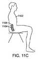
椎間板起因の疼痛を罹患する患者は、疼痛を伴う部分を曲げさせる座位等の位置を回避し、痛みを伴う部分を伸展状態に維持する立位等の位置を好むことによってそれらの症候群を調節する。椎間板起因の疼痛を軽減するための1つのアプローチは、しばしば、会社の椅子に取り付けられている腰支持枕の使用に関与する。生物力学的に、偏在する腰支持枕の目的とした効果はまた、疼痛を伴う腰セグメントを疼痛の少ない伸展位置に維持することである。 Patients with intervertebral disc pain adjust their syndromes by avoiding a position such as a sitting position that bends the painful part and prefers a position such as a standing position that maintains the painful part in an extended state . One approach to reducing discogenic pain often involves the use of waist support pillows that are attached to company chairs. Biomechanically, the intended effect of an unevenly distributed waist support pillow is also to maintain the painful waist segment in an extended position with less pain.
慢性椎間板起因の疼痛と診断された患者のための現在の治療における代替案は、かなり制限されている。多くの患者は、理学療法、マッサージ、抗炎症および鎮痛剤投薬、筋肉弛緩剤、および硬膜外ステロイド注射等のその後の治療コースを受けるが、典型的には、有意な程度の疼痛に悩まされ続ける。他の患者は、通常、隣接椎骨の癒着と共に椎間板切除(椎間板の除去)を必要とする、脊椎固定術を受けることを選択する。癒着はまた、例えば、茎ネジおよび固定ロッドを含む、罹患した脊髄分節の計装を含み得る、または含み得ない。癒着は、それが不可逆的であり、費用がかかり、高い罹患率を伴い、不確かな有効性を有するため、椎間板起因の疼痛に安易に推奨されていない。しかしながら、その短所にも関わらず、椎間板起因の疼痛のための脊椎固定術は、実行可能な代替案がないため、依然として一般的である。 Alternatives in current treatment for patients diagnosed with chronic discogenic pain are quite limited. Many patients receive subsequent treatment courses such as physical therapy, massage, anti-inflammatory and analgesic medications, muscle relaxants, and epidural steroid injections, but typically suffer from a significant degree of pain. to continue. Other patients usually choose to undergo spinal fusion, which requires discectomy (disc removal) with adjacent vertebral fusion. Adhesions can also include or not include instrumentation of the affected spinal cord segment, including, for example, pedicle screws and fixation rods. Adhesions are not easily recommended for disc-related pain because it is irreversible, expensive, has high morbidity, and has uncertain efficacy. However, despite its shortcomings, spinal fusion for intervertebral disc pain remains common because there are no viable alternatives.
実践において一般的に使用されていないが、米国食品医薬品局(FDA)によって使用が認可されている代替的方法は、棘突起または他の椎骨要素を包囲し、それによって、運動に対する拘束を形成する、骨セルクラージュデバイスの適用である。医師は、典型的には、生体構造上に一定の高い力を印加し、1つの位置に分節を固定し、効果的に運動を不可能にさせる、引張または伸長をデバイスに印加する。そのようなデバイスの適用後に可能になった運動の欠如は、同時に実施される癒着の可能性を改善するために有用であると考えられ、癒着が行われない場合には、これらのデバイスは、デバイス、またはデバイスが取り付けられる棘突起の破損により機能しなくなる。これらのデバイスは、備え付け用途のために設計され、可動域にわたる曲げへの動的弾性抵抗を可能にするために設計されるものではない。上述の骨セルクラージュデバイスおよび他の技術の目的は、対象の椎骨分節の測定可能な運動をほぼ完全に制限することである。所与の分節におけるこの運動の喪失は、最終的に隣接分節の罹患率につながる可能性のある、隣接分節における異常な荷重および運動を引き起こす。 An alternative method not commonly used in practice but approved for use by the US Food and Drug Administration (FDA) surrounds the spinous process or other vertebral elements, thereby creating a constraint on movement The application of bone cerclage device. The physician typically applies a constant high force on the anatomy, applying a tension or extension to the device that fixes the segment in one position and effectively disables movement. The lack of movement that has become possible after application of such devices is considered useful to improve the likelihood of simultaneous adhesions, and if no adhesions are made, these devices Failure of the device or the spinous process to which the device is attached will cause it to fail. These devices are designed for installation applications and are not designed to allow dynamic elastic resistance to bending over a range of motion. The purpose of the bone cerclage device and other techniques described above is to almost completely limit the measurable movement of the vertebral segment of interest. This loss of movement in a given segment results in abnormal loading and movement in adjacent segments that can ultimately lead to adjacent segment morbidity.
セルクレージュデバイスに付随する問題のいくつかを回避する代替的解決策は、テザー構造等の脊髄分節に結合される弾性構造の使用に関する。弾性構造は、しばしば、実質的に制限されていない脊髄の伸展を可能にしながら、曲げに対する消極的抵抗を増大することによって、疼痛を緩和することができる。これは、患者が緩和を提供するために既に使用する、姿勢適応の機械的影響を模倣する。 An alternative solution that avoids some of the problems associated with cell clage devices involves the use of elastic structures that are coupled to spinal segments such as tether structures. Elastic structures can often relieve pain by increasing passive resistance to bending while allowing for substantially unrestricted spinal cord extension. This mimics the mechanical effects of posture adaptation that patients already use to provide relief.
テザー構造を使用する脊髄インプラントは、現在、商業的に入手可能である。そのようなインプラントの1つは、それらの茎を介して隣接椎骨を結合する。このインプラントには、スペーサ、テザーおよび茎ネジが挙げられる。インプラントを設置するために、椎間板および椎骨の選択した部分は、除去される。次いで、インプラントは、脊椎の各側面の2つの隣接茎を結合するために配置される。茎ネジは、インプラントを適所に固定する。テザーは、止めネジを用いて茎ネジに締め付けられ、対象の椎骨の伸展/曲げ動作を制限する。有意な組織が除去されるため、かつネジが茎内に配置されるため、インプラントおよび付随する外科方法は、侵襲性が高く、インプラントは、しばしば、不可逆的に埋め込まれる。付随する重要な神経根損傷の機会も存在する。また、止めネジの先端は、テザーを締め付け、これは、微粒子の摩耗粉の生成のテザーの他に摩滅を引き起こし得る。 Spinal implants that use tethered structures are currently commercially available. One such implant connects adjacent vertebrae through their stems. This implant includes spacers, tethers and pedicle screws. To install the implant, the disc and selected portions of the vertebra are removed. The implant is then placed to join two adjacent stems on each side of the spine. The pedicle screw secures the implant in place. The tether is fastened to the pedicle screw using a set screw to limit the extension / bending movement of the subject's vertebra. Because significant tissue is removed and the screw is placed in the stem, the implant and accompanying surgical methods are highly invasive and the implant is often irreversibly implanted. There are also attendant opportunities for significant nerve root damage. The tip of the set screw also tightens the tether, which can cause wear in addition to the tether that produces fine abrasive powder.
テザー構造を使用する他のインプラントは、代わりにそれらの突起を介して隣接椎骨を結合する。これらのインプラントには、テザーおよびスペーサが挙げられる。インプラントを設置するために、棘状靭帯は、一時的に持ち上げられ、置き換えられる。次いで、対象の2つの隣接椎骨の間の棘間靭帯は、永久的に除去され、スペーサは、棘間の隙間に挿入される。次いで、テザーは、隣接棘間靭帯を介して2つの隣接椎骨の突起の周に巻き付けられ、次いで、スペーサによって、またはスペーサに締結された個別の構成要素によって、機械的に適所に固定される。次いで、棘状靭帯は、その本来の位置に再度戻される。そのようなインプラントおよび付随する外科的方法は、不都合が存在しないわけではない。これらのインプラントは、棘突起を日々の活動中の頻繁な高荷重にさらし、しばしば、棘突起の破損または低下を引き起こし得る。さらに、スペーサは、患者を、矢状面バランスの欠如に付随する長期の臨床問題に潜在的につながる分節脊柱後弯症にさせ得る。テザーを固定するプロセスは、しばしば、外科医が実施するには非常に複雑な手順であり、外科手術をより侵襲性にさせる。また、前述のように、棘間靭帯の除去は、永久的である。そのため、デバイスの適用は可逆的ではない。 Other implants that use tethered structures instead connect adjacent vertebrae through their protrusions. These implants include tethers and spacers. To place the implant, the spinous ligament is temporarily lifted and replaced. The interspinous ligament between the two adjacent vertebrae of interest is then permanently removed and a spacer is inserted into the interspinous gap. The tether is then wrapped around the process of two adjacent vertebrae via adjacent interspinous ligaments and then mechanically secured in place by spacers or by individual components fastened to the spacers. The spinal ligament is then returned again to its original position. Such implants and the accompanying surgical methods are not without disadvantages. These implants expose the spinous processes to frequent high loads during day-to-day activities and can often cause the spinous processes to break or fall. In addition, the spacer may cause the patient to have segmental kyphosis that can potentially lead to long-term clinical problems associated with lack of sagittal balance. The process of securing the tether is often a very complex procedure for the surgeon to perform, making the surgery more invasive. Also, as described above, the removal of the interspinous ligament is permanent. As such, device application is not reversible.
ごく近年では、侵襲性の少ない脊髄インプラントが導入されている。前述のインプラントのように、これらの脊髄インプラントは、1対以上の棘突起の上に配置され、湾曲中に生じる棘突起の広がりに対する弾性拘束を提供する。しかしながら、伸展を制限するスペーサは、使用されず、棘間靭帯は、永久的に除去されない。そのため、これらのインプラントは、侵襲性が少なく、可逆的に埋め込まれ得る。インプラントは、典型的には、テザー構造およびテザーのための固定機構を含む。テザーは、ポリエステル(PET)またはポリエチレン(例えば、超高分子量のポリエチレン、UHMWPE)織物等の可撓性ポリマー布地、マルチストランドケーブル、または他の可撓性構造から作製され得る。テザーは、隣接椎骨の突起の周りに巻きつけられ、次いで、固定機構によって固定される。固定機構は、テザーおよびストラップの指標付けに関与し得、例えば、テザーおよび固定機構は、その2つを連結する、歯、フック、ループ等の不連続界面を含む。また、非常に強力な圧着を使用して、固定機構を用いてテザーを押圧し、連結し得る。多くの公知の埋込は、止めネジの先端、または締結部のネジ山部分を用いてテザーを圧着する。しかしながら、脊髄インプラントに印加された機械力は、相互にインターフェースする、テザーおよび固定機構の特定の部分に向かって非均一に分配される。したがって、これらの部分は、典型的には、摩滅、摩耗、または他の損傷をより受けやすく、したがって、これらの脊髄インプラント全体の信頼性を低下させる。他の公知の方法は、他の構成要素を共に引き出し、圧着力を生成するためにネジまたはボルトを使用する。他の係止方法は、摩擦嵌合の使用を含み、下記により詳細に開示する。これらの方法は、潜在的に損傷させる荷重を回避し得る一方で、アセンブリの機械的複雑性は、さらに付属部品を導入することによって増大し得る。 Very recently, less invasive spinal implants have been introduced. Like the previously described implants, these spinal implants are placed over one or more pairs of spinous processes and provide elastic constraints on the extent of the spinous processes that occur during bending. However, spacers that limit extension are not used and the interspinous ligaments are not permanently removed. Therefore, these implants are less invasive and can be reversibly implanted. Implants typically include a tether structure and a locking mechanism for the tether. The tether can be made from a flexible polymer fabric, such as polyester (PET) or polyethylene (eg, ultra high molecular weight polyethylene, UHMWPE) fabric, multi-strand cables, or other flexible structures. The tether is wrapped around the adjacent vertebral process and then fixed by a fixation mechanism. The fixation mechanism may be involved in indexing the tether and strap, for example, the tether and the fixation mechanism include discontinuous interfaces such as teeth, hooks, loops, etc. that connect the two. Also, a very strong crimp can be used to press and connect the tether using a securing mechanism. Many known implants use a set screw tip or a threaded portion of a fastening portion to crimp the tether. However, the mechanical force applied to the spinal implant is distributed non-uniformly towards the specific parts of the tether and fixation mechanism that interface with each other. Thus, these portions are typically more susceptible to wear, wear, or other damage, thus reducing the overall reliability of these spinal implants. Other known methods use screws or bolts to pull the other components together and generate a crimping force. Other locking methods include the use of a friction fit and are disclosed in more detail below. While these methods can avoid potentially damaging loads, the mechanical complexity of the assembly can be increased by introducing additional accessories.
上述の多くの棘突起拘束デバイスの適切な埋込への鍵は、棘突起の周りに巻かれている時に、デバイスの引張または寸法を調節することである。バンドが適切に調節されていない場合には、それは、緩過ぎる可能性があり、したがって、生体構造から係脱し得る、または曲げへの適切な抵抗を提供せず、それによって、疼痛または不安定性の緩和の失敗をもたらし得る。一方、バンドがきつ過ぎる、または小さ過ぎる場合には、デバイスは、曲げへの過剰な抵抗を提供し得、脊髄分節の曲げ能力を不必要に制限し、椎骨または軟組織の部分に対して必要以上の荷重を生じ得る。したがって、棘突起デバイスの寸法/引張力を適切に調節することは必須である。デバイスは、理想的には、患者が好ましい姿勢(例えば、起立位置)にある間に規定および好ましい構造を有さなければならず、デバイスはまた、依然として脊髄分節の有意に制限されない伸展を可能にしながら、脊髄分節の曲げに抵抗する力を提供しなければならない。前述の理由のため、脊髄分節に人工装具を結合し、特に整形外科的内固定手術中に人工装具を調節するための改善された方法および装置を提供することが望ましいであろう。特に、そのような方法および装置は、実行するために容易であり、最小侵襲性でなければならない。 The key to proper implantation of many of the spinous process restraint devices described above is to adjust the tension or size of the device as it is wrapped around the spinous process. If the band is not properly adjusted, it may be too loose and therefore disengage from the anatomy or does not provide adequate resistance to bending, thereby causing pain or instability May lead to mitigation failures. On the other hand, if the band is too tight or too small, the device may provide excessive resistance to bending, unnecessarily restricting the bending ability of the spinal segment and more than necessary for vertebral or soft tissue parts Can cause a load of. Therefore, it is essential to properly adjust the size / tensile force of the spinous process device. The device should ideally have a defined and preferred structure while the patient is in a preferred position (eg, standing position), and the device also allows for a significantly unrestricted extension of the spinal cord segment. However, it must provide a force that resists bending of the spinal segment. For the foregoing reasons, it would be desirable to provide an improved method and apparatus for coupling a prosthesis to a spinal segment and adjusting the prosthesis, particularly during orthopedic internal fixation procedures. In particular, such methods and devices must be easy to perform and minimally invasive.
(2.背景技術の記述)
対象の特許および発行された明細書には、米国特許第3,648,691号、同第4,643,178号、同第4,743,260号、同第4,966,600号、同第5,011,494号、同第5,092,866号、同第5,116,340号、同第5,180,393号、同第5,282,863号、同第5,395,374号、同第5,415,658号、同第5,415,661号、同第5,449,361号、同第5,456,722号、同第5,462,542号、同第5,496,318号、同第5,540,698号、同第5,562,737号、同第5,609,634号、同第5,628,756号、同第5,645,599号、同第5,725,582号、同第5,902,305号、同第36,221号、同第5,928,232号、同第5,935,133号、同第5,964,769号、同第5,989,256号、同第6,053,921号、同第6,248,106号、同第6,312,431号、同第6,364,883号、同第6,378,289号、同第6,391,030号、同第6,468,309号、同第6,436,099号、同第6,451,019号、同第6,582,433号、同第6,605,091号、同第6,626,944号、同第6,629,975号、同第6,652,527号、同第6,652,585号、同第6,656,185号、同第6,669,729号、同第6,682,533号、同第6,689,140号、同第6,712,819号、同第6,689,168号、同第6,695,852号、同第6,716,245号、同第6,761,720号、同第6,835,205号、同第7,029,475号、同第7,163,558号、米国特許出願公開第2002/0151978号、同第2004/0024458号、同第2004/0106995号、同第2004/0116927号、同第2004/0117017号、同第2004/0127989号、同第2004/0172132号、同第2004/0243239号、同第2005/0033435号、同第2005/0049708号、同第2005/0192581号、同第2005/0216017号、同第2006/0069447号、同第2006/0136060号、同第2006/0240533号、同第2007/0213829号、同第2007/0233096号、同第2008/0009866号、同第2008/0108993、PCT国際公開WO01/28442 A1号、同WO02/03882 A2号、同WO02/051326 A1号、同WO02/071960 A1号、同WO03/045262 A1号、同WO2004/052246 A1号、同WO2004/073532 A1号、同WO2008/051806号、同WO2008/051423号、同WO2008/051801号、同WO2008/051802、および外国特許出願公開第EP0322334 A1号、および第FR2 681 525 A1号が挙げられる。脊髄分節に適用された可撓性拘束の機械的特性は、Papp et al.(1997)Spine 22:151〜155、Dickman et al.(1997)Spine 22:596〜604、およびGarner et al(2002)Eur.Spine J.S186〜S191、A1 Baz et al(1995)Spine 20,No.11,1241〜1244、Heller,(1997)Arch.Orthopedic and Trauma Surgery,117,No.1〜2:96〜99、Leahy et al.(2000)Proc.Inst.Mech.Eng.Part H:J.Eng.Med.214,No.5:489〜495、Minns et al.,(1997)Spine 22 No.16:1819〜1825、Miyasaka et al.(2000)Spine 25,No.6:732〜737、Shepherd et al.(2000)Spine 25,No.3:319〜323、Shepherd(2001)Medical Eng.Phys.23,No.2:135〜141、ならびにVoydeville et al(1992)Orthop Traumatol 2:259〜264に説明されている。(2. Description of background art)
The subject patents and issued specifications include US Pat. Nos. 3,648,691, 4,643,178, 4,743,260, 4,966,600, 5,011,494, 5,092,866, 5,116,340, 5,180,393, 5,282,863, 5,395, No. 374, No. 5,415,658, No. 5,415,661, No. 5,449,361, No. 5,456,722, No. 5,462,542, No. 5,496,318, 5,540,698, 5,562,737, 5,609,634, 5,628,756, 5,645,599 No. 5,721,582, No. 5,902,305, No. 36,221, No. No. 5,928,232, No. 5,935,133, No. 5,964,769, No. 5,989,256, No. 6,053,921, No. 6,248,106. 6,312,431, 6,364,883, 6,378,289, 6,391,030, 6,468,309, 6, 436,099, 6,451,019, 6,582,433, 6,605,091, 6,626,944, 6,629,975, 6,652,527, 6,652,585, 6,656,185, 6,669,729, 6,682,533, 6,689 No. 140, No. 6,712,819, No. 6,689,168, No. 6,695,85 No. 6,716,245, No. 6,761,720, No. 6,835,205, No. 7,029,475, No. 7,163,558, US patent application Published 2002/0151978, 2004/0024458, 2004/0106995, 2004/0116927, 2004/0117017, 2004/0127989, 2004/0172132, 2004 No. 2004/0243239, No. 2005/0033435, No. 2005/0049708, No. 2005/0192581, No. 2005/0216017, No. 2006/0069447, No. 2006/0136060, No. 2006/0240533, 2007/0213829, second 007/0233096, 2008/0009866, 2008/0108993, PCT International Publication WO01 / 28442 A1, WO02 / 03882 A2, WO02 / 051326 A1, WO02 / 071960 A1, WO03 No. 045262 A1, No. WO 2004/052246 A1, No. WO 2004/073532 A1, No. WO 2008/051806, No. WO 2008/051423, No. WO 2008/051801, No. WO 2008/051802, and Foreign Patent Application Publication No. EP0322334 A1 No., and FR2 681 525 A1. The mechanical properties of the flexible restraint applied to the spinal cord segment are described in Papp et al. (1997) Spine 22: 151-155, Dickman et al. (1997) Spine 22: 596-604, and Garner et al (2002) Eur. Spine J. et al. S186-S191, A1 Baz et al (1995) Spine 20, No. 5; 11, 1241-1244, Heller, (1997) Arch. Orthopedic and Trauma Surgery, 117, no. 1-2: 96-99, Leahy et al. (2000) Proc. Inst. Mech. Eng. Part H: J.M. Eng. Med. 214, no. 5: 489-495, Minns et al. , (1997) Spine 22 No. 16: 1819-1825, Miyasaka et al. (2000) Spine 25, no. 6: 732-737, Shepherd et al. (2000) Spine 25, no. 3: 319-323, Shepherd (2001) Medical Eng. Phys. 23, no. 2: 135-141, as well as Voydeville et al (1992) Orthotraumol 2: 259-264.
本発明は、人工装具を脊髄分節に結合し、整形外科適内固定手術中に人工装具を調節するために使用される方法および装置に関する。これには、脊髄疼痛または他の脊髄症状を有する患者の治療が挙げられるが、それに限定されない。 The present invention relates to a method and apparatus used to couple a prosthesis to a spinal segment and adjust the prosthesis during orthopedic internal fixation surgery. This includes, but is not limited to, treating patients with spinal pain or other spinal symptoms.
本発明の第1の側面においては、患者の脊髄分節に人工装具を結合するための方法は、脊髄分節に沿って配置される第1および第2の基準点を選択するステップと、手術前に標的距離を測定するステップとを含む。標的距離は、患者が好ましい姿勢である間に、第1の基準点と第2の基準点との間に延在する。本方法はまた、脊髄分節に人工装具を結合するステップと、標的距離に基づき、第1の基準点と第2の基準点との間の距離を設定するために、手術中に人工装具を調節するステップとを含む。 In a first aspect of the invention, a method for coupling a prosthesis to a patient's spinal segment includes selecting first and second reference points that are positioned along the spinal segment, and prior to surgery. Measuring a target distance. The target distance extends between the first reference point and the second reference point while the patient is in a preferred posture. The method also adjusts the prosthesis during surgery to set a distance between the first reference point and the second reference point based on the target distance and coupling the prosthesis to the spinal segment. Including the step of.
第1の基準点は、第1の椎骨上に配置され得、第2の基準点は、椎骨または仙骨の上に配置され得る。第1の基準点はまた、第1の椎骨の第1の棘突起の上面上に配置され得、第2の基準点は、第2の椎骨の第2の棘突起の下面上に配置され得る。第1の基準点はまた、第1の椎骨の第1の棘突起の下面上に配置され得、第2の基準点は、第2の椎骨の第2の棘突起の上面上に配置され得る。第1の椎骨は、第2の椎骨の頭方に配置され得る。好ましい姿勢は、起立位置または痛みを伴わない位置を含み得る。 The first reference point may be placed on the first vertebra and the second reference point may be placed on the vertebra or sacrum. The first reference point may also be located on the upper surface of the first spinous process of the first vertebra, and the second reference point may be located on the lower surface of the second spinous process of the second vertebra. . The first reference point may also be disposed on the lower surface of the first spinous process of the first vertebra and the second reference point may be disposed on the upper surface of the second spinous process of the second vertebra. . The first vertebra may be placed on the head of the second vertebra. Preferred postures may include a standing position or a painless position.
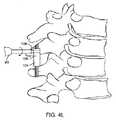
標的距離を測定するステップは、患者が好ましい姿勢である間に撮影された、患者の放射線写真を観察するステップを含み得る。放射線写真は、手術前に撮影され得、脊髄分節の側面図を含み得る。人工装具は、テザー構造を含み得、結合するステップは、テザーの第1の部分を上棘突起と係合するステップと、テザー構造の第2の部分を内棘突起または仙骨と係合するステップとを含み得る。 Measuring the target distance may include observing a radiograph of the patient taken while the patient is in a preferred posture. The radiograph can be taken before surgery and can include a side view of the spinal cord segment. The prosthesis may include a tether structure, and the coupling step includes engaging a first portion of the tether with the superior spinous process and engaging a second portion of the tether structure with the internal spinous process or sacrum. Can be included.
調節するステップは、患者が好ましい姿勢である時に、人工装具が中立位置にあり、人工装具が、依然として、脊髄分節の有意に制限されていない伸展を可能にしながら、脊髄分節の曲げに抵抗する力を提供するように、人工装具を調節するステップを含み得る。調節するステップはまた、患者が好ましい姿勢以外の位置である間に、人工装具を調節するステップ、または人工装具上の較正マーキングを観察するステップを含み得る。調節するステップはまた、第1の基準点と第2の基準点との間の距離を標的距離に設定するステップを含み得る。 The adjusting step is a force that resists bending of the spinal segment while the prosthesis is in a neutral position when the patient is in a preferred position and the prosthesis still allows for significant unrestricted extension of the spinal segment. Adjusting the prosthesis to provide The adjusting step may also include adjusting the prosthesis or observing calibration markings on the prosthesis while the patient is in a position other than the preferred posture. The adjusting step may also include setting a distance between the first reference point and the second reference point as a target distance.
本方法は、第1の基準点と第2の基準点との間の距離が標的距離に実質的に一致することを確認するステップをさらに含み得る。確認するステップは、第1の基準点と第2の基準点との間の距離を決定するためにゲージを使用するステップを含み得る。本方法はまた、第1の基準点と第2の基準点との間の距離が標的距離に実質的に一致するまで、人工装具を再調節するステップをさらに含み得る。 The method may further include confirming that the distance between the first reference point and the second reference point substantially matches the target distance. The step of confirming may include using a gauge to determine the distance between the first reference point and the second reference point. The method may also further include readjusting the prosthesis until the distance between the first reference point and the second reference point substantially matches the target distance.
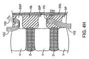
人工装具は、第1のコンプライアンス要素(compliance element)を備え、本方法は、人工装具の調節中に、その伸展または収縮を制限するために、第1の拘束装置を第1のコンプライアンス要素と係合し、係止するステップをさらに含み得る。第1の拘束装置は、その移動を可能にするように、第1のコンプライアンス要素から係脱され得る。人工装具はまた、第2のコンプライアンス要素を備え得、本方法は、人工装具の調節中に、その伸展または収縮を制限するために、第2の拘束装置を第2のコンプライアンス要素と係合するステップを含み得る。第1および第2の拘束装置は、脊髄分節の正中線の対向側の第1および第2のコンプライアンス要素の整列および位置付けを容易にするように結合され得る。第1の拘束装置は、様々な厚さの棘突起または正中線靭帯(例えば、棘間靭帯および棘上靭帯)に適応するために、1つの自由度に沿って第2の拘束装置に対して移動させられ得る。ドライバまたはツールは、第1または第2の拘束装置の中心管腔内に位置付けられ、それによって、コンプライアンス要素上の係止機構を用いてドライバまたはツールを同心円状に整列させ得る。拘束装置を使用して、第1または第2のコンプライアンス要素が調節される時、または第1または第2の拘束装置が共に解放可能に係止される時に、反対トルクを提供し得る。人工装具は、所望の値までプレテンションを加えられ得る。 The prosthesis includes a first compliance element, and the method engages the first restraining device with the first compliance element to limit its extension or contraction during adjustment of the prosthesis. A step of combining and locking may further be included. The first restraining device can be disengaged from the first compliance element to allow its movement. The prosthesis may also include a second compliance element, and the method engages the second restraining device with the second compliance element to limit its extension or contraction during adjustment of the prosthesis. Steps may be included. The first and second restraining devices may be coupled to facilitate alignment and positioning of the first and second compliance elements opposite the midline of the spinal cord segment. The first restraining device is relative to the second restraining device along one degree of freedom to accommodate various thicknesses of spinous processes or midline ligaments (eg, interspinous and supraspinal ligaments). Can be moved. The driver or tool may be positioned within the central lumen of the first or second restraining device, thereby using a locking mechanism on the compliance element to align the driver or tool concentrically. The restraining device may be used to provide an opposite torque when the first or second compliance element is adjusted, or when the first or second restraining devices are releasably locked together. The prosthesis can be pretensioned to a desired value.
標的距離は、長軸長を画定し、調節するステップは、標的人工装具円周を決定するために標的距離を使用するステップと、標的円周に人工装具を調節するステップとを含む。長軸長は、参照テーブル内の標的円周または人工装具上の較正マーキングと相関し得る。 The target distance defines and adjusts the major axis length, including using the target distance to determine the target prosthesis circumference and adjusting the prosthesis to the target circumference. The major axis length may be correlated with a target circumference in the lookup table or a calibration marking on the prosthesis.
本方法はまた、人工装具円周が標的円周に実質的に一致することを確認するステップを含み得る。人工装具円周を確認するステップは、人工装具上の較正マーキングを観察するステップを含み得る。人工装具は、人工装具円周が標的円周に実質的に一致するまで再調節され得る。 The method may also include confirming that the prosthetic circumference substantially matches the target circumference. Checking the prosthesis circumference may include observing calibration markings on the prosthesis. The prosthesis can be readjusted until the prosthetic circumference substantially matches the target circumference.
本方法はまた、脊髄分節に沿って配置される、第3および第4の基準点を選択するステップを含み得る。第3および第4の基準点の間の距離は、短軸長を有する短軸を画定し、短軸は、長軸に対して直角である。本方法はまた、標的人工装具円周を決定するために、手術前画像上の短軸長を測定するステップを含み得る。標的円周は、人工装具において、上棘突起および下棘突起を包囲するループを形成するために十分である。人工装具は、所望の姿勢を超えた曲げに抵抗する力を提供し得る。第3および第4の基準点は、棘突起についての対向側にあり得、棘突起幅に適応する必要がある、人工装具の長さを推定し得る。第3および第4の基準点は、単一の椎骨上に配置され得る。短軸長は、参照テーブル内の標的円周と相関し得るか、または短軸長は、人工装具上の較正マーキングと相関し得る。本方法はさらに、脊髄分節の一部分を減圧するステップを含み得る。 The method may also include selecting third and fourth reference points that are positioned along the spinal cord segment. The distance between the third and fourth reference points defines a minor axis having a minor axis length, the minor axis being perpendicular to the major axis. The method may also include measuring a minor axis length on the pre-operative image to determine a target prosthesis circumference. The target circumference is sufficient to form a loop that surrounds the upper and lower spinous processes in the prosthesis. The prosthesis may provide a force that resists bending beyond a desired posture. The third and fourth reference points may be on opposite sides for the spinous process and may estimate the length of the prosthesis that needs to be adapted to the spinous process width. The third and fourth reference points can be placed on a single vertebra. The short axis length can correlate with the target circumference in the lookup table, or the short axis length can correlate with calibration markings on the prosthesis. The method may further comprise depressurizing a portion of the spinal segment.
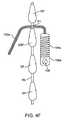
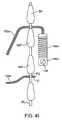
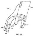
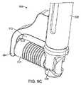
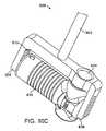
本発明の別の側面においては、患者の脊髄分節の曲げを制限するためのシステムは、上棘突起、および下棘突起または仙骨と結合されるように適合される、テザー構造と、テザー構造と結合される、第1のコンプライアンス要素とを備える。本システムはまた、コンプライアンス要素を所望の位置に保持するように、またはコンプライアンス要素の運動を規定の範囲に制限するように、コンプライアンス要素と解放可能に結合される、第1の拘束ツールを含む。テザー構造は、実質的に非伸張性であり得、第1の拘束ツールは、細長いシャフトを備え得る。第1の拘束ツールは、第1のコンプライアンス要素を解放可能に保持するように適合される、クレードルを備え得る。第1の拘束ツールはまた、第1のコンプライアンス要素を解放可能に保持するためのレセプタクルを形成し、コンプライアンス要素の伸長を拘束する、複数の細長いアームを備え得る。第1のツールは、第1のコンプライアンス要素を所望の緊張状態に保持し得る。圧縮力は、可変であり得る。 In another aspect of the invention, a system for limiting bending of a patient's spinal segment is a tether structure adapted to be coupled with an upper spinous process and a lower spinous process or sacrum, and a tether structure. A first compliance element coupled. The system also includes a first restraining tool that is releasably coupled to the compliance element to hold the compliance element in a desired position or to limit the movement of the compliance element to a defined range. The tether structure can be substantially inextensible and the first restraining tool can comprise an elongate shaft. The first restraining tool may comprise a cradle that is adapted to releasably hold the first compliance element. The first restraining tool may also include a plurality of elongate arms that form a receptacle for releasably holding the first compliance element and restrain extension of the compliance element. The first tool may hold the first compliance element in a desired tension state. The compression force can be variable.
第1の拘束ツールは、第1のコンプライアンス要素が規定の距離に延在するまで、第1のコンプライアンス要素の伸展を制限し得ない。第1の拘束ツールは、所望の位置、引張力、または範囲を変化させるように調節可能であり得る。本システムはまた、テザー構造と結合される、第2のコンプライアンス要素と、第2の拘束ツールとを備え得る。第2のツールは、第2のコンプライアンス要素を所望の位置に保持するように、または第2のコンプライアンス要素の動作を規定の範囲に制限するように、第2のコンプライアンス要素と解放可能に結合され得る。第1および第2の拘束ツールは、脊髄分節の正中線の対向側の第1および第2のコンプライアンス要素の整合および位置付けを容易にするように、解放可能かつ対称的に共に結合され得る。第1および第2の拘束ツールは、1つの自由度に沿って、相互に対して移動可能であり、それによって、様々な厚さの棘突起または正中線軟組織に適応し得る。第1または第2のコンプライアンス要素は、係止機構を備え得、第1または第2の拘束ツールのうちの少なくとも1つは、係止機構を用いて同心円状にドライバまたは他のツールを受容し、整列させるように適合される管腔を有する細長いシャフトを備え得る。第1または第2のコンプライアンス要素は、第1または第2の拘束ツールを用いて解放可能に係止する。第1または第2の拘束ツールはまた、係止機構が作動させられると、反対トルクを提供するように適合され得る。 The first restraining tool cannot limit the extension of the first compliance element until the first compliance element extends a defined distance. The first restraining tool may be adjustable to change the desired position, tension, or range. The system may also include a second compliance element and a second restraining tool coupled to the tether structure. The second tool is releasably coupled with the second compliance element to hold the second compliance element in a desired position or to limit the operation of the second compliance element to a defined range. obtain. The first and second restraining tools may be releasably and symmetrically coupled together to facilitate alignment and positioning of the first and second compliance elements opposite the midline of the spinal cord segment. The first and second restraining tools are movable relative to one another along one degree of freedom, thereby adapting to various thicknesses of spinous processes or midline soft tissue. The first or second compliance element may comprise a locking mechanism, and at least one of the first or second constraint tools receives a driver or other tool concentrically using the locking mechanism. May comprise an elongate shaft having a lumen adapted to be aligned. The first or second compliance element is releasably locked using the first or second restraining tool. The first or second restraining tool may also be adapted to provide an opposite torque when the locking mechanism is activated.
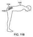
本発明の別の側面においては、患者の背下部痛を治療するための方法は、背下部を様々な曲げ位置に配置するように患者に指示を提供するステップと、患者が背下部痛を経験しない、または背下部痛が軽減される、背下部の閾値位置を決定するステップとを含み得る。閾値位置にある間の患者の背下部の第1の画像または一組の画像を提供し、患者の背下部の特徴は、第1の画像または一組の画像を使用して測定される。拘束デバイスは、患者の背下部に結合し、それに結合された拘束デバイスによって、背下部の特徴は、再測定される。再測定された特徴は、測定された特徴と比較され、患者の背下部が、測定された特徴と再測定された特徴との比較に基づく閾値位置より下の位置にあるように調節される。したがって、背下部痛または背下部の不安定性が軽減されるか、または排除される。 In another aspect of the invention, a method for treating lower back pain in a patient includes providing instructions to the patient to place the lower back in various bending positions, and the patient experiences lower back pain. Determining a threshold position of the lower back where no lower back pain is relieved. A first image or set of images of the patient's lower back while in the threshold position is provided, and the patient's lower back features are measured using the first image or set of images. The restraining device is coupled to the lower back of the patient, and the lower back features are re-measured by the restraining device coupled thereto. The remeasured feature is compared to the measured feature and adjusted so that the patient's lower back is at a position below a threshold position based on the comparison of the measured feature with the remeasured feature. Thus, lower back pain or lower back instability is reduced or eliminated.
決定するステップは、疼痛が経験される時を示すための手段を患者に提供するステップを含み得る。本手段は、作動可能なスイッチを備え得る。第1の画像または一組の画像は、X線、MRI、およびCTスキャンのうちの1つを含み得る。提供するステップは、疼痛を感じる姿勢と疼痛を感じない姿勢または疼痛が軽減された姿勢との間の患者の背下部の単一の連続動作から、一組の画像を取得するステップを含み得る。 The determining step may include providing the patient with a means to indicate when pain is experienced. The means may comprise an operable switch. The first image or set of images may include one of X-rays, MRI, and CT scans. The providing step may include obtaining a set of images from a single continuous motion of the patient's lower back between a pain-sensing posture and a pain-free or pain-relieving posture.
測定された特徴は、椎骨板間の角度、棘突起間の距離、および弓根間の距離のうちの1つを含み得る。測定するステップは、特徴を定量化するためにキャリパまたは角度測定デバイスを使用するステップを含み得る。 The measured feature may include one of an angle between vertebral discs, a distance between spinous processes, and a distance between pedicles. Measuring may include using a caliper or angle measurement device to quantify the feature.
結合するステップは、拘束デバイスを上棘突起および下棘突起または仙骨と係合するステップを含み得る。拘束デバイスは、背下部の曲げに抵抗する力を提供するように適合され得る。 Coupling may include engaging the restraining device with the upper and lower spinous processes or sacrum. The restraining device may be adapted to provide a force that resists bending of the lower back.
再測定するステップは、それに接合された拘束デバイスによって、患者の背下部の第2の画像または一組の画像を提供するステップを含み得る。第2の画像または一組の画像は、X線、MRI、またはCTスキャンのうちの1つを含み得る。再測定するステップは、1つ以上の放射線不透過性マーカーを患者の背下部と係合するように配置するステップを含み得る。放射線不透過性マーカーは、患者の背下部の棘突起と結合し得る。比較するステップは、第1および第2の放射線画像または複数組の画像を視覚的に比較するステップを含み得る。調節するステップは、拘束デバイスにおける長さまたは引張力を調節するステップを含み得る。 Re-measuring may include providing a second image or set of images of the patient's lower back with a restraining device bonded thereto. The second image or set of images may include one of X-ray, MRI, or CT scan. The re-measuring step may include positioning one or more radiopaque markers to engage the lower back of the patient. The radiopaque marker may bind to the spinous processes on the patient's lower back. The comparing step may include visually comparing the first and second radiographic images or sets of images. Adjusting may include adjusting a length or tension in the restraining device.
本方法はさらに、それに拘束デバイスを結合するための、背下部の棘突起の存在および形状を評価するステップを含み得る。背下部内の面関節係合はまた、評価され得る。評価するステップは、面関節の関節突起の線形重複を測定するステップを含み得る。拘束デバイスを調節するステップは、背下部内の少なくとも1つの面関節における面関節係合を増大させるように、拘束デバイスを調節するステップを含み得る。調節するステップはまた、背下部内の少なくとも1つの面関節の過伸展または係止を防止するように、拘束デバイスを調節するステップを含み得る。本方法はさらに、背下部が測定および再測定された特徴の比較に基づく閾値位置の位置に、またはそれより下の位置にあるように、患者の背下部を手術中に操作するステップを含み得る。操作するステップは、その中で脊柱前弯症を形成または増大するように、患者の背下部を操作するステップを含み得る。 The method may further include assessing the presence and shape of the lower spinous process for coupling a restraining device thereto. Facial joint engagement within the lower back can also be evaluated. The step of evaluating can include measuring a linear overlap of the articular process of the facet joint. Adjusting the restraining device may include adjusting the restraining device to increase facet joint engagement in at least one facet joint in the lower back. The adjusting step may also include adjusting the restraining device to prevent overextension or locking of at least one face joint in the lower back. The method may further include manipulating the patient's lower back during surgery such that the lower back is at or below a threshold position based on a comparison of measured and remeasured features. . The step of manipulating may include manipulating the lower back of the patient so as to form or increase lordosis.
本発明の別の側面においては、患者の背下部の変性脊椎すべり症を治療するための方法は、背下部を様々な曲げ位置に配置するように患者に指示を提供するステップと、様々な位置の背下部の複数の画像を提供するステップとを含み得る。患者の背下部内の面関節が亜脱臼し始める、背下部の閾値位置が決定され、次いで、閾値位置にある間の患者の背下部の第1の画像が提供される。拘束デバイスを患者の背下部に結合し、拘束デバイスが患者の背下部に結合された後に、手術中に患者の背中の第2の画像を提供する。第1および第2の画像を比較し、患者の背下部が第1および第2の画像の比較に基づく閾値位置より下の位置にあるように、拘束デバイスを調節する。したがって、関節の亜脱臼は、低減または排除される。 In another aspect of the invention, a method for treating degenerative spondylolisthesis of a patient's lower back provides instructions to the patient to place the lower back in various bending positions; Providing a plurality of images of the lower back of the body. A lower back threshold position is determined at which the face joint in the patient's lower back begins to subluxation, and then a first image of the patient's lower back is provided while in the threshold position. A restraining device is coupled to the lower back of the patient, and a second image of the patient's back is provided during surgery after the restraining device is coupled to the lower back of the patient. The first and second images are compared and the restraint device is adjusted so that the patient's lower back is in a position below a threshold position based on the comparison of the first and second images. Thus, subluxation of the joint is reduced or eliminated.
決定するステップは、作動可能なスイッチ等の疼痛が経験される時を示すための手段を患者に提供するステップを含み得る。決定するステップはまた、尾椎骨に関して、面関節の係合または頭蓋椎骨の前方並進に抵抗する面関節の能力を評価するステップを含み得る。 The determining step may include providing the patient with a means for indicating when pain is experienced, such as an actuated switch. The determining step may also include evaluating the ability of the face joint to resist face joint engagement or anterior translation of the cranial vertebra with respect to the tail vertebra.
第1の画像は、X線、MRI、またはCTスキャンのうちの1つを含み得る。結合するステップは、拘束デバイスを上棘突起および下棘突起または仙骨と係合するステップを含み得る。拘束デバイスは、背下部の曲げに抵抗する力を提供するように適合され得る。第2の画像は、X線、MRI、またはCTスキャンを含み得る。1つ以上の放射線不透過性マーカーを患者の背下部と係合するように配置し得る。配置は、放射線不透過性マーカーを患者の背下部の棘突起と結合するステップを含み得る。 The first image may include one of X-ray, MRI, or CT scan. Coupling may include engaging the restraining device with the upper and lower spinous processes or sacrum. The restraining device may be adapted to provide a force that resists bending of the lower back. The second image can include an x-ray, MRI, or CT scan. One or more radiopaque markers may be positioned to engage the patient's lower back. The placement may include coupling a radiopaque marker with a spinous process on the patient's lower back.
比較するステップは、第1および第2の画像、または複数の組の画像間の椎骨版間の角度、棘突起間の距離、面関節係合、または弓根間の距離を比較するステップを含み得る。比較するステップはまた、第1および第2の画像の背下部の特徴を定量化するためにキャリパまたは角度測定デバイスを使用するステップを含み得る。第1および第2の画像は、視覚的に比較され得る。 The step of comparing may include comparing the angle between the vertebral plates, the distance between spinous processes, the facet joint engagement, or the distance between the pedicles between the first and second images or sets of images. . The comparing step may also include using a caliper or angle measurement device to quantify the features of the lower back of the first and second images. The first and second images can be visually compared.
調節するステップは、拘束デバイスにおける長さまたは引張力を調節するステップを含み得る。本方法はまた、それに拘束デバイスを結合するための、背下部の棘突起の存在および形状を評価するステップを含み得る。 Adjusting may include adjusting a length or tension in the restraining device. The method may also include assessing the presence and shape of the spinal process of the lower back for coupling a restraining device thereto.
本発明の別の側面においては、患者の背下部痛を治療するための方法は、背下部痛が軽減または排除される位置に患者の背下部を操作するステップと、その位置を記録するステップとを含む。患者の背下部においてその位置を手術中に再現し、拘束デバイスを背下部に結合する。 In another aspect of the invention, a method for treating a patient's lower back pain includes manipulating the patient's lower back to a position where the lower back pain is reduced or eliminated, and recording the position. including. The position is reproduced during surgery on the lower back of the patient and a restraint device is coupled to the lower back.
操作するステップは、患者の背下部を手動で操作するステップと、患者の背下部において脊柱前弯症を形成または増大するステップとを含み得る。操作するステップはまた、調節可能な腰部部材を伴う枠または椅子に患者を配置するステップと、股関節を曲げさせるステップとを含み得る。股関節を曲げさせるステップは、骨盤を前傾させるように、大腿骨頭を通して近位方向に力を方向付け、それによって、患者の背下部において脊柱前弯症を形成または増大するステップを含み得る。膝は、拘束され得る。 The manipulating step may include manually manipulating the lower back of the patient and forming or augmenting lordosis in the lower back of the patient. The manipulating step may also include placing the patient in a frame or chair with an adjustable waist member and bending the hip joint. Bending the hip joint may include directing a force proximally through the femoral head to tilt the pelvis forward, thereby creating or increasing lordosis in the lower back of the patient. The knee can be restrained.
記録するステップは、作動可能なスイッチ等の疼痛が経験される時を示すための手段を患者に提供するステップを含み得る。再現するステップは、患者の背下部をその位置に手動で操作するステップ、または患者の背下部において脊柱前弯症を形成または増大するステップを含み得る。結合するステップは、拘束デバイスを上棘突起および下棘突起または仙骨と係合するステップを含み得る。拘束デバイスは、背下部の曲げに抵抗する力を提供するように適合され得る。 The step of recording may include providing the patient with a means for indicating when pain is experienced, such as an actuated switch. The step of reproducing may include manually manipulating the patient's lower back to that position, or forming or augmenting lordosis in the lower back of the patient. Coupling may include engaging the restraining device with the upper and lower spinous processes or sacrum. The restraining device may be adapted to provide a force that resists bending of the lower back.
本方法はさらに、その位置にある患者の背下部の画像を提供するステップを含み得る。画像は、X線、MRI、またはCTスキャンを含み得る。本方法はまた、位置を再現した後に、患者の背下部の手術中画像を提供するステップを含み得る。手術中画像は、X線、Cアーム蛍光透視法、MRI、およびCTスキャンのうちの1つを含み得る。放射線不透過性マーカーは、棘突起等の患者の背下部と結合され得る。本方法はさらに、患者の背下部の分節の可動域、分節安定性、線形剛性、または曲げ剛性を手術中に特徴付けるステップを含み得る。拘束デバイスは、患者の背下部の特徴付けに基づき調節され得る。調節するステップは、拘束デバイスにおける長さまたは引張力を調節するステップを含み得る。また、患者の背下部の特徴付けは、参照ガイドと比較され得、拘束デバイスは、参照ガイドによって提供される情報に基づき調節され得る。 The method may further include providing an image of the patient's lower back at that location. The image may include an x-ray, MRI, or CT scan. The method may also include providing an intraoperative image of the patient's lower back after reproducing the position. The intraoperative image may include one of X-ray, C-arm fluoroscopy, MRI, and CT scan. Radiopaque markers can be coupled to the patient's lower back, such as spinous processes. The method may further include characterizing the range of motion, segmental stability, linear stiffness, or bending stiffness of the patient's lower back during surgery. The restraining device may be adjusted based on the characterization of the patient's lower back. Adjusting may include adjusting a length or tension in the restraining device. Also, the patient's lower back characterization can be compared to a reference guide and the restraint device can be adjusted based on information provided by the reference guide.
本発明のさらに別の側面においては、患者の脊椎すべり症を治療するための方法は、背下部を様々な曲げ位置に配置するように患者に指示を提供するステップと、患者が並進不安定性を経験しないか、または並進不安定性が軽減される、背下部の閾値位置を決定するステップとを含む。患者の背下部の第1の画像または一組の画像は、患者が閾値位置にある間に提供され、患者の背下部の特徴は、第1の画像または一組の画像から測定される。拘束デバイスを患者の背下部に結合し、それに結合された拘束デバイスによって患者の背下部の特徴を再測定する。再測定された特徴を、測定された特徴と比較し、患者の背下部が、測定および再測定された特徴の比較に基づく閾値位置より下の位置にあり、それによって、背下部の不安定性が軽減または排除されるように、拘束デバイスを調節する。 In yet another aspect of the invention, a method for treating a patient's spondylolisthesis includes providing instructions to the patient to place the lower back in various bending positions; Determining a threshold position of the lower back that is not experienced or in which translational instability is reduced. A first image or set of images of the patient's lower back is provided while the patient is in the threshold position, and features of the patient's lower back are measured from the first image or set of images. A restraint device is coupled to the patient's lower back and the patient's lower back features are remeasured by the restraint device coupled thereto. The remeasured feature is compared to the measured feature and the patient's lower back is in a position below a threshold position based on the comparison of the measured and remeasured feature, thereby reducing lower back instability. Adjust the restraint device to be reduced or eliminated.
これらおよび他の実施形態を付属の図面に関連する以下の説明において、さらに詳細に説明する。
本発明は、例えば以下の項目を提供する。
(項目1)
患者の脊髄分節に人工装具を結合するための方法であって、該方法は、
該脊髄分節に沿って配置される第1の基準点および第2の基準点を選択するステップと、
標的距離を手術前に測定するステップであって、該標的距離は、該患者が好ましい姿勢である間に該第1の基準点と第2の基準点との間に延在する、ステップと、
該人工装具を該脊髄分節に結合するステップと、
該標的距離に基づいて、該第1の基準点と第2の基準点との間の距離を設定するために、該人工装具を手術中に調節するステップと
を含む、方法。
(項目2)
前記第1の基準点は、第1の椎骨上に配置され、前記第2の基準点は、第2の椎骨または仙骨上に配置される、項目1に記載の方法。
(項目3)
前記第1の基準点は、第1の椎骨の棘突起の上面上に配置され、前記第2の基準点は、第2の椎骨の第2の棘突起の下面上に配置され、該第1の椎骨は、該第2の椎骨の頭方に配置される、項目1に記載の方法。
(項目4)
前記第1の基準点は、第1の椎骨の第1の棘突起の下面上に配置され、前記第2の基準点は、第2の椎骨の第2の棘突起の上面上に配置され、該第1の椎骨は、該第2の椎骨の頭方に配置される、項目1に記載の方法。
(項目5)
前記好ましい姿勢は、起立位置を含む、項目1に記載の方法。
(項目6)
前記好ましい姿勢は、痛みを伴わない位置を含む、項目1に記載の方法。
(項目7)
前記測定するステップは、前記患者が前記好ましい姿勢である間に撮影された、該患者の放射線写真を観察するステップを含む、項目1に記載の方法。
(項目8)
前記放射線写真は、手術前に撮影される、項目7に記載の方法。
(項目9)
前記放射線写真は、前記脊髄分節の側面図を含む、項目7に記載の方法。
(項目10)
前記人工装具は、テザー構造を備え、前記結合するステップは、該テザー構造の第1の部分を上棘突起と係合するステップと、該テザー構造の第2の部分を下棘突起または仙骨と係合するステップとを含む、項目1に記載の方法。
(項目11)
前記調節するステップは、前記人工装具を調節するステップを含み、それにより、前記患者が前記好ましい姿勢である時に、該人工装具は中立位置にあり、該人工装具が、依然として前記脊髄分節の有意に制限されていない伸展を可能にしながら、該脊髄分節の曲げに抵抗する力を提供する、項目1に記載の方法。
(項目12)
前記調節するステップは、前記患者が前記好ましい姿勢以外の位置にある間に、前記人工装具を調節するステップを含む、項目1に記載の方法。
(項目13)
前記調節するステップは、その上の較正マーキングを観察するステップを含む、項目1に記載の方法。
(項目14)
前記調節するステップは、前記第1の基準点と第2の基準点との間の距離を前記標的距
離に設定するステップを含む、項目1に記載の方法。
(項目15)
前記第1の基準点と第2の基準点との間の距離が、前記標的距離に実質的に一致するステップを確認するステップをさらに含む、項目1に記載の方法。
(項目16)
前記確認するステップは、前記第1の基準点と第2の基準点との間の距離を決定するためにゲージを使用するステップを含む、項目15に記載の方法。
(項目17)
前記第1の基準点と第2の基準点との間の距離が、前記標的距離に実質的に一致するまで、人工装具を再調節するステップをさらに含む、項目15に記載の方法。
(項目18)
前記人工装具は、第1のコンプライアンス要素を備え、前記方法は、該人工装具の調節中に、第1の拘束装置を該第1のコンプライアンス要素に係合し、係止して、該コンプライアンス要素の伸展または収縮を制限するステップをさらに含む、項目1に記載の方法。
(項目19)
前記第1のコンプライアンス要素から前記第1の拘束装置を係脱するステップにより、該コンプライアンス要素の移動を可能にするステップをさらに含む、項目18に記載の方法。
(項目20)
前記人工装具は、第2のコンプライアンス要素を備え、前記方法は、
該人工装具の調節中に、第2の拘束装置を該第2のコンプライアンス要素と係合するステップにより、該第2のコンプライアンス要素の伸展または収縮を制限するステップと、
前記第1および第2の拘束装置を共に解放可能に係止するステップにより、前記脊髄分節の正中線についての反対側の前記第1のコンプライアンス要素と該第2のコンプライアンス要素との整列および位置付けを容易にするステップと
をさらに含む、項目18に記載の方法。
(項目21)
1つの自由度に沿って、前記第2の拘束装置に対して前記第1の拘束装置を移動させるステップをさらに含み、それにより、様々な厚さの棘突起および棘間/棘上靭帯複合体に適応する、項目20に記載の方法。
(項目22)
前記第1または第2の拘束装置の中心管腔内にドライバまたはツールを位置付け、それによって、前記コンプライアンス要素上の係止機構を用いて該ドライバまたはツールを同心円状に整列させるステップをさらに含む、項目20に記載の方法。
(項目23)
前記第1または第2のコンプライアンス要素が調節される時、または前記第1および第2の拘束装置が共に解放可能に係止される時に、反対のトルクを提供するステップをさらに含む、項目20に記載の方法。
(項目24)
前記人工装具に所望の値までプレテンションを加えるステップをさらに含む、項目1に記載の方法。
(項目25)
前記標的距離は、長軸長を画定し、前記調節するステップは、標的人工装具円周を決定するために該標的距離を使用するステップと、該標的円周に該人工装具を調節するステップとを含む、項目1に記載の方法。
(項目26)
前記長軸長は、参照テーブル内の前記標的円周と相関している、項目25に記載の方法。
(項目27)
前記長軸長は、前記人工装具上の較正マーキングと相関している、項目25に記載の方法。
(項目28)
前記人工装具円周が前記標的円周に実質的に一致するステップを確認するステップをさらに含む、項目25に記載の方法。
(項目29)
前記人工装具円周を確認するステップは、前記人工装具上の較正マーキングを観察するステップを含む、項目28に記載の方法。
(項目30)
前記人工装具円周が前記標的円周に実質的に一致するまで、前記人工装具を再調節するステップをさらに含む、項目28に記載の方法。
(項目31)
前記脊髄分節に沿って配置される第3の基準点および第4の基準点を選択するステップであって、該第3の基準点と第4の基準点との間の距離は、短軸長を有する短軸を画定し、該短軸は、前記長軸に対して直角である、ステップと、
前記標的人工装具円周を決定するために、手術前画像上に該短軸長を測定するステップであって、該標的円周は、該人工装具が上棘突起および下棘突起を包囲するループを形成し、所望の姿勢を超えた曲げに抵抗する力を提供するステップに十分である、ステップと
をさらに含む、項目25に記載の方法。
(項目32)
前記第3および第4の基準点は、棘突起についての対向側にあり、棘突起幅に適応する必要がある前記人工装具の長さを推定する、項目31に記載の方法。
(項目33)
前記第3および第4の基準点は、単一の椎骨上に配置される、項目31に記載の方法。
(項目34)
前記短軸長は、参照テーブル内の前記標的円周と相関している、項目31に記載の方法。
(項目35)
前記短軸長は、前記人工装具上の較正マーキングと相関している、項目31に記載の方法。
(項目36)
前記脊髄分節の一部分を減圧するステップをさらに含む、項目1に記載の方法。
(項目37)
患者の脊髄分節の曲げを制限するためのシステムであって、
上棘突起と、下棘突起または仙骨と結合されるように適合されるテザー構造と、
該テザー構造と結合される第1のコンプライアンス要素と、
該コンプライアンス要素を所望の位置に保持するために、または該コンプライアンス要素の運動を規定の範囲に制限するために、該コンプライアンス要素と解放可能に結合される第1の拘束ツールと
を備える、システム。
(項目38)
前記テザー構造は、実質的に非伸張性である、項目37に記載のシステム。
(項目39)
前記第1の拘束ツールは、細長いシャフトを備える、項目37に記載のシステム。
(項目40)
前記第1の拘束ツールは、前記第1のコンプライアンス要素を解放可能に保持するように適合されるクレードルを備える、項目37に記載のシステム。
(項目41)
前記第1の拘束ツールは、複数の細長いアームを備え、該複数のアームは、前記コンプ
ライアンス要素の伸長に対する拘束を形成する、項目37に記載のシステム。
(項目42)
前記第1のツールは、第1のコンプライアンス要素を所望の緊張状態に保持する、項目37に記載のシステム。
(項目43)
前記第1の拘束ツールは、前記第1のコンプライアンス要素に圧縮力を印加する、項目37に記載のシステム。
(項目44)
前記圧縮力は、可変である、項目43に記載のシステム。
(項目45)
前記第1の拘束ツールは、前記第1のコンプライアンス要素が規定の距離に延在するまで、該第1のコンプライアンス要素の伸展を制限しない、項目37に記載のシステム。
(項目46)
前記第1の拘束ツールは、前記所望の位置、緊張状態、または範囲を変化させるように調節可能である、項目37に記載のシステム。
(項目47)
前記テザー構造と結合される第2のコンプライアンス要素と、
該第2のコンプライアンス要素を所望の位置に保持するために、または該第2のコンプライアンス要素の動作を規定の範囲に制限するために、該第2のコンプライアンス要素と解放可能に結合される第2の拘束ツールと
をさらに備え、
前記第1および該第2の拘束ツールは、前記脊髄分節の正中線についての対向する側の前記第1のコンプライアンス要素と該第2のコンプライアンス要素との整列および位置付けを容易にするために、解放可能かつ対称的に共に結合される、項目37に記載のシステム。
(項目48)
前記第1および前記第2の拘束ツールは、1つの自由度に沿って、相互に対して移動可能であり、それによって、様々な厚さの棘突起に適応する、項目47に記載のシステム。
(項目49)
前記第1または前記第2のコンプライアンス要素は、係止機構を備え、前記第1または前記第2の拘束ツールのうちの少なくとも1つは、該係止機構を用いて同心円状にドライバまたは他のツールを受容し、整列させるように適合される管腔を有する細長いシャフトを備える、項目47に記載のシステム。
(項目50)
前記第1または前記第2のコンプライアンス要素は、前記第1または前記第2の拘束ツールを用いて解放可能に係止する、項目47に記載のシステム。
(項目51)
前記第1または前記第2の拘束ツールは、前記係止機構が作動させられると、反対のトルクを提供するように適合される、項目49に記載のシステム。
(項目52)
患者の背下部痛を治療するための方法であって、該方法は、
該背下部を様々な曲げ位置に配置するために該患者に指示を提供するステップと、
該患者が背下部痛を経験しないか、または背下部痛が軽減される該背下部の閾値位置を決定するステップと、
該閾値位置にある間に該患者の背下部の第1の画像または一組の画像を提供するステップと、
該第1の画像または該一組の画像から該患者の背下部の特徴を測定するステップと、
拘束デバイスを該患者の背下部に結合するステップと、
該患者の背下部の特徴を、それに結合された該拘束デバイスによって再測定するステッ
プと、
該再測定された特徴を、該測定された特徴と比較するステップと、
該測定された特徴と再測定された特徴との比較に基づいて、該患者の背下部が、該閾値位置より下の位置にあるように該拘束デバイスを調節するステップであって、それにより、該背下部痛または該背下部の不安定性が軽減または排除される、ステップと
を含む、方法。
(項目53)
前記決定するステップは、疼痛が経験される時を示すための手段を前記患者に提供するステップを含む、項目52に記載の方法。
(項目54)
前記手段は、作動可能なスイッチを備える、項目53に記載の方法。
(項目55)
前記第1の画像または前記一組の画像は、X線、MRI、およびCTスキャンのうちの1つを含む、項目52に記載の方法。
(項目56)
前記提供するステップは、疼痛を感じる姿勢と、疼痛を感じない姿勢または疼痛が軽減された姿勢との間の前記患者の背下部の単一の連続動作から、前記一組の画像を取得するステップを含む、項目52に記載の方法。
(項目57)
前記測定された特徴は、椎骨板間の角度、棘突起間の距離、および弓根間の距離のうちの1つを含む、項目52に記載の方法。
(項目58)
前記測定するステップは、前記特徴を定量化するためのキャリパまたは角度測定デバイスを使用するステップを含む、項目57に記載の方法。
(項目59)
前記結合するステップは、前記拘束デバイスを上棘突起と、下棘突起または仙骨と係合するステップを含む、項目52に記載の方法。
(項目60)
前記拘束デバイスは、前記背下部の曲げに抵抗する力を提供するように適合される、項目52に記載の方法。
(項目61)
前記再測定するステップは、前記患者の背下部の第2の画像または一組の画像を、それに結合された前記拘束デバイスによって提供するステップを含む、項目52に記載の方法。
(項目62)
前記第2の画像または前記一組の画像は、X線、MRI、またはCTスキャンのうちの1つを含む、項目61に記載の方法。
(項目63)
前記再測定するステップは、1つ以上の放射線不透過性マーカーを前記患者の背下部と係合するように配置するステップを含む、項目61に記載の方法。
(項目64)
前記配置するステップは、前記放射線不透過性マーカーのうちの少なくとも1つを前記患者の背下部の棘突起と結合するステップを含む、項目63に記載の方法。
(項目65)
前記比較するステップは、前記第1の放射線画像と前記第2の放射線画像または複数組の画像とを視覚的に比較するステップを含む、項目61に記載の方法。
(項目66)
調節するステップは、前記拘束デバイスの長さまたは緊張状態を調節するステップを含む、項目52に記載の方法。
(項目67)
前記背下部の棘突起の存在および形状を、それに前記拘束デバイスを結合するために評価するステップをさらに含む、項目52に記載の方法。
(項目68)
前記背下部内の面関節係合を評価するステップをさらに含む、項目52に記載の方法。
(項目69)
前記評価するステップは、関節突起の線状の重複を測定するステップを含む、項目68に記載の方法。
(項目70)
前記拘束デバイスを調節する前記ステップは、前記背下部内の少なくとも1つの面関節における面関節係合を増大させるために、該拘束デバイスを調節するステップを含む、項目52に記載の方法。
(項目71)
前記拘束デバイスを調節する前記ステップは、前記背下部内の少なくとも1つの面関節の過伸展または係止を防止するために、該拘束デバイスを調節するステップを含む、項目52に記載の方法。
(項目72)
前記背下部が、測定された特徴と再測定された特徴との比較に基づく前記閾値位置の位置、またはそれより下の位置にあるように前記患者の背下部を手術中に操作するステップをさらに含む、項目52に記載の方法。
(項目73)
前記操作するステップは、前記患者の背下部を、その中で脊柱前弯症を形成または増大させるように操作するステップを含む、項目72に記載の方法。
(項目74)
患者の背下部の変性脊椎すべり症を治療するための方法であって、該方法は、
該背下部を様々な曲げ位置に配置するために、該患者に指示を提供するステップと、
該様々な位置の該背下部の複数の画像を提供するステップと、
該患者の背下部内の面関節が亜脱臼し始める、該背下部の閾値位置を決定するステップと、
該閾値位置にある間に該患者の背下部の第1の画像を提供するステップと、
拘束デバイスを該患者の背下部に結合するステップと、
該拘束デバイスが該患者の背下部に結合された後に、手術中の該患者の背中の第2の画像を提供するステップと、
該第1の画像と該第2の画像とを比較するステップと、
該患者の背下部が、該第1の画像と該第2の画像との比較に基づく該閾値位置より下の位置にあり、それにより、該面関節の該亜脱臼が軽減または排除されるように該拘束デバイスを調節するステップと
を含む、方法。
(項目75)
前記決定するステップは、疼痛が経験される時を示すための手段を前記患者に提供するステップを含む、項目74に記載の方法。
(項目76)
前記手段は、作動可能なスイッチを備える、項目75に記載の方法。
(項目77)
神経減圧を同時に実施するステップをさらに含む、項目74に記載の方法。
(項目78)
前記決定するステップは、前記患者の背下部の同時減圧によって、またはよらずに面関節の係合を評価するステップを含む、項目74に記載の方法。
(項目79)
前記第1の画像は、X線、MRI、またはCTスキャンのうちの1つを含む、項目7
4に記載の方法。
(項目80)
前記結合するステップは、前記拘束デバイスを上棘突起と、下棘突起または仙骨と係合するステップを含む、項目74に記載の方法。
(項目81)
前記拘束デバイスは、前記背下部の曲げに抵抗する力を提供するように適合される、項目74に記載の方法。
(項目82)
前記第2の画像は、X線を含む、項目74に記載の方法。
(項目83)
1つ以上の放射線不透過性マーカーを前記患者の背下部と係合するように配置するステップをさらに含む、項目82に記載の方法。
(項目84)
前記配置するステップは、前記放射線不透過性マーカーのうちの少なくとも1つを前記患者の背下部の棘突起と結合するステップを含む、項目83に記載の方法。
(項目85)
前記比較するステップは、前記第1の画像と、前記第2の画像、または複数の組の画像との間の椎骨板間の角度、棘突起間の距離、面関節係合、または弓根間の距離を比較するステップを含む、項目74に記載の方法。
(項目86)
前記比較するステップは、前記第1および前記第2の画像の背下部の特徴を定量化するためにキャリパまたは角度測定デバイスを使用するステップを含む、項目74に記載の方法。
(項目87)
前記比較するステップは、前記第1の画像と前記第2の画像とを視覚的に比較するステップを含む、項目74に記載の方法。
(項目88)
前記調節するステップは、前記拘束デバイスにおける長さまたは緊張状態を調節するステップを含む、項目74に記載の方法。
(項目89)
前記背下部の棘突起の存在および形状を、それに前記拘束デバイスを結合するために評価するステップをさらに含む、項目74に記載の方法。
(項目90)
患者の背下部痛を治療するための方法であって、該方法は、
該背下部痛が軽減または排除される位置に該患者の背下部を操作するステップと、
該位置を記録するステップと、
該患者の背下部において該位置を手術中に再現するステップと、
拘束デバイスを該背下部に結合するステップと
を含む、方法。
(項目91)
前記操作するステップは、前記患者の背下部を手動で操作するステップを含む、項目90に記載の方法。
(項目92)
前記操作するステップは、前記患者の背下部において脊柱前弯症を形成または増大させるステップを含む、項目90に記載の方法。
(項目93)
前記操作するステップは、調節可能な腰部部材によって枠または椅子に前記患者を配置するステップを含む、項目90に記載の方法。
(項目94)
前記操作するステップは、股関節を曲げさせるステップを含む、項目90に記載の方
法。
(項目95)
前記股関節を曲げさせるステップは、骨盤を前傾させるために大腿骨頭を通して近位方向に力を方向付け、それによって、前記患者の背下部において脊柱前弯症を形成または増大させるステップを含む、項目94に記載の方法。
(項目96)
膝を拘束するステップをさらに含む、項目95に記載の方法。
(項目97)
前記記録するステップは、疼痛が経験される時を示すための手段を前記患者に提供するステップを含む、項目90に記載の方法。
(項目98)
前記手段は、作動可能なスイッチを備える、項目97に記載の方法。
(項目99)
前記再現するステップは、前記患者の背下部を前記位置に手動で操作するステップを含む、項目90に記載の方法。
(項目100)
前記再現するステップは、前記患者の背下部において脊柱前弯症を形成または増大させるステップを含む、項目90に記載の方法。
(項目101)
前記結合するステップは、前記拘束デバイスを上棘突起と、下棘突起または仙骨と係合するステップを含む、項目90に記載の方法。
(項目102)
前記拘束デバイスは、前記背下部の曲げに抵抗する力を提供するように適合される、項目101に記載の方法。
(項目103)
前記位置にある前記患者の背下部の画像を提供するステップをさらに含む、項目90に記載の方法。
(項目104)
前記画像は、X線を含む、項目103に記載の方法。
(項目105)
前記位置を再現した後に、前記患者の背下部の手術中画像を提供するステップをさらに含む、項目90に記載の方法。
(項目106)
前記手術中画像は、X線、MRI、およびCTスキャンのうちの1つを含む、項目105に記載の方法。
(項目107)
放射線不透過性マーカーを前記患者の背下部と結合するステップをさらに含む、項目90に記載の方法。
(項目108)
前記放射線不透過性マーカーは、前記患者の背下部の棘突起と結合される、項目107に記載の方法。
(項目109)
前記患者の背下部の分節の可動域、分節安定性、線形剛性、または曲げ剛性を手術中に特徴付けるステップをさらに含む、項目90に記載の方法。
(項目110)
前記患者の背下部の前記特徴付けに基づいて、前記拘束デバイスを調節するステップをさらに含む、項目109に記載の方法。
(項目111)
前記調節するステップは、前記拘束デバイスにおける長さまたは緊張状態を調節するステップを含む、項目110に記載の方法。
(項目112)
前記患者の背下部の特徴付けを参照ガイドと比較するステップと、
該参照ガイドによって提供される情報に基づいて、前記拘束デバイスを調節するステップと
をさらに含む、項目109に記載の方法。
(項目113)
患者の脊椎すべり症を治療するための方法であって、
背下部を様々な曲げ位置に配置するように該患者に指示を提供するステップと、
該背下部の閾値位置を決定するステップであって、該閾値位置において、該患者は並進不安定性を経験しないか、または並進不安定性が軽減される、ステップと、
該閾値位置にある間の該患者の背下部の第1の画像または一組の画像を提供するステップと、
該第1の画像または該一組の画像から該患者の背下部の特徴を測定するステップと、
拘束デバイスを該患者の背下部に結合するステップと、
該患者の背下部の特徴を、それに結合された該拘束デバイスによって再測定するステップと、
該再測定された特徴を該測定された特徴と比較するステップと、
該患者の背下部が、測定の特徴と再測定された特徴との比較に基づく該閾値位置より下の位置にあり、それにより、該背下部の不安定性が軽減または排除されるように、該拘束デバイスを調節するステップと
を含む、方法。These and other embodiments are described in further detail in the following description, taken in conjunction with the accompanying drawings.
For example, the present invention provides the following items.
(Item 1)
A method for connecting a prosthesis to a patient's spinal segment, the method comprising:
Selecting a first reference point and a second reference point located along the spinal cord segment;
Measuring a target distance before surgery, the target distance extending between the first and second reference points while the patient is in a preferred posture;
Coupling the prosthesis to the spinal cord segment;
Adjusting the prosthesis during surgery to set a distance between the first reference point and a second reference point based on the target distance;
Including the method.
(Item 2)
The method of
(Item 3)
The first reference point is disposed on the upper surface of the spinous process of the first vertebra, and the second reference point is disposed on the lower surface of the second spinous process of the second vertebra. 2. The method of
(Item 4)
The first reference point is disposed on the lower surface of the first spinous process of the first vertebra, and the second reference point is disposed on the upper surface of the second spinous process of the second vertebra; 2. The method of
(Item 5)
The method according to
(Item 6)
The method of
(Item 7)
The method of
(Item 8)
Item 8. The method according to Item 7, wherein the radiograph is taken before surgery.
(Item 9)
8. The method of item 7, wherein the radiograph includes a side view of the spinal cord segment.
(Item 10)
The prosthesis comprises a tether structure, and the coupling step includes engaging a first portion of the tether structure with an upper spinous process, and a second portion of the tether structure with a lower spinous process or sacrum. The method of
(Item 11)
The step of adjusting includes adjusting the prosthesis so that when the patient is in the preferred posture, the prosthesis is in a neutral position and the prosthesis is still significantly in the spinal segment. The method of
(Item 12)
The method of
(Item 13)
The method of
(Item 14)
In the adjusting step, the distance between the first reference point and the second reference point is set to the target distance.
The method of
(Item 15)
The method of
(Item 16)
16. The method of
(Item 17)
16. The method of
(Item 18)
The prosthesis comprises a first compliance element, and the method engages and locks a first restraining device to the first compliance element during adjustment of the prosthesis, the compliance element. 2. The method of
(Item 19)
19. The method of item 18, further comprising allowing movement of the compliance element by disengaging the first restraining device from the first compliance element.
(Item 20)
The prosthesis comprises a second compliance element, the method comprising:
Limiting the expansion or contraction of the second compliance element by engaging a second restraining device with the second compliance element during adjustment of the prosthesis;
Releasably locking the first and second restraining devices together to align and position the first and second compliance elements on opposite sides of the midline of the spinal cord segment With steps to facilitate
The method according to item 18, further comprising:
(Item 21)
Further comprising moving the first restraint device relative to the second restraint device along one degree of freedom, thereby providing various thicknesses of spinous processes and interspinous / supraspinal ligament composites. Item 21. The method according to Item 20, wherein
(Item 22)
Further comprising positioning a driver or tool within a central lumen of the first or second restraining device, thereby concentrically aligning the driver or tool with a locking mechanism on the compliance element; Item 21. The method according to Item 20.
(Item 23)
Item 20 further comprising providing an opposite torque when the first or second compliance element is adjusted, or when the first and second restraining devices are both releasably locked together. The method described.
(Item 24)
2. The method of
(Item 25)
The target distance defines a major axis length and the adjusting step uses the target distance to determine a target prosthesis circumference; and adjusting the prosthesis to the target circumference The method according to
(Item 26)
26. The method of item 25, wherein the major axis length is correlated with the target circumference in a lookup table.
(Item 27)
26. The method of item 25, wherein the major axis length is correlated with a calibration marking on the prosthesis.
(Item 28)
26. The method of item 25, further comprising the step of identifying a step in which the prosthetic circumference substantially matches the target circumference.
(Item 29)
29. A method according to item 28, wherein the step of ascertaining the prosthesis circumference comprises observing calibration markings on the prosthesis.
(Item 30)
29. The method of item 28, further comprising the step of readjusting the prosthesis until the prosthetic circumference substantially matches the target circumference.
(Item 31)
Selecting a third reference point and a fourth reference point arranged along the spinal cord segment, the distance between the third reference point and the fourth reference point being a short axis length Defining a minor axis having the steps of: perpendicular to the major axis; and
Measuring the minor axis length on a pre-operative image to determine the target prosthesis circumference, the target circumference being a loop in which the prosthesis surrounds the upper and lower spinous processes Sufficient to provide a force that resists bending beyond the desired posture, forming and
26. The method of item 25, further comprising:
(Item 32)
32. The method of item 31, wherein the third and fourth reference points are on opposite sides of the spinous process and estimate the length of the prosthesis that needs to be adapted to the spinous process width.
(Item 33)
32. The method of item 31, wherein the third and fourth reference points are located on a single vertebra.
(Item 34)
32. The method of item 31, wherein the minor axis length is correlated with the target circumference in a lookup table.
(Item 35)
32. The method of item 31, wherein the minor axis length is correlated with a calibration marking on the prosthesis.
(Item 36)
The method of
(Item 37)
A system for limiting the bending of a patient's spinal segment,
An upper spinous process and a tether structure adapted to be coupled with the lower spinous process or sacrum;
A first compliance element coupled to the tether structure;
A first constraining tool releasably coupled to the compliance element to hold the compliance element in a desired position or to limit movement of the compliance element to a defined range;
A system comprising:
(Item 38)
38. A system according to item 37, wherein the tether structure is substantially inextensible.
(Item 39)
38. The system of item 37, wherein the first restraining tool comprises an elongate shaft.
(Item 40)
38. The system of item 37, wherein the first restraining tool comprises a cradle adapted to releasably hold the first compliance element.
(Item 41)
The first restraining tool includes a plurality of elongate arms, the plurality of arms including the compressor.
38. A system according to item 37, which forms a constraint on extension of the liaison element.
(Item 42)
38. The system of item 37, wherein the first tool holds the first compliance element in a desired tension state.
(Item 43)
38. The system of item 37, wherein the first restraining tool applies a compressive force to the first compliance element.
(Item 44)
44. A system according to item 43, wherein the compressive force is variable.
(Item 45)
38. The system of item 37, wherein the first restraining tool does not limit extension of the first compliance element until the first compliance element extends a defined distance.
(Item 46)
38. The system of item 37, wherein the first restraining tool is adjustable to change the desired position, tension state, or range.
(Item 47)
A second compliance element coupled to the tether structure;
A second releasably coupled to the second compliance element to hold the second compliance element in a desired position or to limit the operation of the second compliance element to a specified range. The constraint tool and
Further comprising
The first and second restraining tools are released to facilitate alignment and positioning of the first compliance element and the second compliance element on opposite sides of the midline of the spinal cord segment 38. A system according to item 37, which is coupled together as possible and symmetrically.
(Item 48)
48. The system of item 47, wherein the first and second constraint tools are movable relative to one another along one degree of freedom, thereby adapting to various thicknesses of spinous processes.
(Item 49)
The first or second compliance element includes a locking mechanism, and at least one of the first or second restraining tools is concentrically configured using the locking mechanism with a screwdriver or other 48. The system of item 47, comprising an elongate shaft having a lumen adapted to receive and align the tool.
(Item 50)
48. The system of item 47, wherein the first or second compliance element is releasably locked using the first or second restraining tool.
(Item 51)
50. The system of item 49, wherein the first or second restraining tool is adapted to provide an opposite torque when the locking mechanism is actuated.
(Item 52)
A method for treating lower back pain in a patient comprising:
Providing instructions to the patient to place the lower back in various bending positions;
Determining a lower threshold position at which the patient does not experience lower back pain or at which lower back pain is reduced;
Providing a first image or set of images of the patient's lower back while in the threshold position;
Measuring features of the lower back of the patient from the first image or the set of images;
Coupling a restraining device to the lower back of the patient;
A step of re-measuring features of the lower back of the patient with the restraining device coupled thereto.
And
Comparing the remeasured feature to the measured feature;
Adjusting the restraint device so that the lower back of the patient is in a position below the threshold position based on a comparison of the measured and re-measured characteristics, thereby: The lower back pain or lower back instability is reduced or eliminated, and
Including the method.
(Item 53)
53. The method of item 52, wherein the determining step includes providing the patient with a means for indicating when pain is experienced.
(Item 54)
54. A method according to item 53, wherein the means comprises an actuatable switch.
(Item 55)
53. The method of item 52, wherein the first image or the set of images includes one of X-ray, MRI, and CT scan.
(Item 56)
The providing step includes acquiring the set of images from a single continuous movement of the lower back of the patient between a pain-sensing posture and a pain-free or pain-relieving posture. 53. The method of item 52, comprising:
(Item 57)
53. The method of item 52, wherein the measured characteristics include one of an angle between vertebral discs, a distance between spinous processes, and a distance between pedicles.
(Item 58)
58. The method of item 57, wherein the measuring step comprises using a caliper or an angle measurement device to quantify the feature.
(Item 59)
53. The method of item 52, wherein the coupling step includes engaging the restraining device with an upper spinous process and a lower spinous process or sacrum.
(Item 60)
53. The method of item 52, wherein the restraining device is adapted to provide a force that resists bending of the lower back.
(Item 61)
53. The method of item 52, wherein the re-measuring step includes providing a second image or set of images of the lower back of the patient with the restraining device coupled thereto.
(Item 62)
62. A method according to item 61, wherein the second image or the set of images includes one of X-ray, MRI, or CT scan.
(Item 63)
62. The method of item 61, wherein the re-measuring step includes positioning one or more radiopaque markers to engage the lower back of the patient.
(Item 64)
64. The method of item 63, wherein the placing step comprises coupling at least one of the radiopaque markers with a spinous process in the patient's lower back.
(Item 65)
62. The method of item 61, wherein the step of comparing includes the step of visually comparing the first radiographic image and the second radiographic image or sets of images.
(Item 66)
53. The method of item 52, wherein the adjusting step includes adjusting a length or tension state of the restraining device.
(Item 67)
53. The method of item 52, further comprising evaluating the presence and shape of the lower spinous process to couple the restraint device thereto.
(Item 68)
53. The method of item 52, further comprising evaluating a facet joint engagement in the lower back.
(Item 69)
69. The method of item 68, wherein the step of evaluating includes measuring a linear overlap of the articular process.
(Item 70)
53. The method of item 52, wherein the step of adjusting the restraint device comprises adjusting the restraint device to increase facet joint engagement at at least one facet joint in the lower back.
(Item 71)
53. The method of item 52, wherein the step of adjusting the restraining device comprises adjusting the restraining device to prevent overextension or locking of at least one facet joint in the lower back.
(Item 72)
Manipulating the patient's lower back during surgery such that the lower back is at or below the threshold position based on a comparison of the measured and remeasured features 53. The method of item 52, comprising.
(Item 73)
73. A method according to item 72, wherein the manipulating step includes manipulating the lower back of the patient to form or increase lordosis in the patient.
(Item 74)
A method for treating degenerative spondylolisthesis in a patient's lower back, the method comprising:
Providing instructions to the patient to place the lower back in various bending positions;
Providing a plurality of images of the lower back of the various locations;
Determining a threshold position of the lower back where the facet joint in the lower back of the patient begins to subluxate;
Providing a first image of the lower back of the patient while in the threshold position;
Coupling a restraining device to the lower back of the patient;
Providing a second image of the patient's back during surgery after the restraining device is coupled to the lower back of the patient;
Comparing the first image and the second image;
The patient's lower back is in a position below the threshold position based on the comparison of the first image and the second image, thereby reducing or eliminating the subluxation of the facet joint Adjusting the restraining device to
Including the method.
(Item 75)
75. The method of item 74, wherein the determining step includes providing the patient with a means for indicating when pain is experienced.
(Item 76)
76. The method of item 75, wherein the means comprises an actuatable switch.
(Item 77)
75. The method of item 74, further comprising the step of simultaneously performing nerve decompression.
(Item 78)
75. The method of item 74, wherein the determining step comprises assessing facet joint engagement with or without simultaneous decompression of the patient's lower back.
(Item 79)
Item 7 wherein the first image includes one of X-ray, MRI, or CT scan.
4. The method according to 4.
(Item 80)
75. The method of item 74, wherein the coupling step includes engaging the restraining device with an upper spinous process and a lower spinous process or sacrum.
(Item 81)
75. The method of item 74, wherein the restraining device is adapted to provide a force that resists bending of the lower back.
(Item 82)
75. The method of item 74, wherein the second image includes x-rays.
(Item 83)
83. The method of item 82, further comprising placing one or more radiopaque markers in engagement with the lower back of the patient.
(Item 84)
84. The method of item 83, wherein the placing step comprises coupling at least one of the radiopaque markers with a spinous process in the patient's lower back.
(Item 85)
The comparing step includes: an angle between vertebral discs between the first image and the second image or sets of images, a distance between spinous processes, a facet joint engagement, or between pedicles. 75. A method according to item 74, comprising comparing the distances.
(Item 86)
75. The method of item 74, wherein the comparing step includes using a caliper or an angle measurement device to quantify lower back features of the first and second images.
(Item 87)
75. The method of item 74, wherein the comparing step includes a step of visually comparing the first image and the second image.
(Item 88)
75. The method of item 74, wherein the adjusting step includes adjusting a length or tension in the restraining device.
(Item 89)
75. The method of item 74, further comprising evaluating the presence and shape of the lower spinous process to couple the restraint device thereto.
(Item 90)
A method for treating lower back pain in a patient comprising:
Manipulating the patient's lower back to a position where the lower back pain is reduced or eliminated;
Recording the position;
Reproducing the position during surgery in the lower back of the patient;
Coupling a restraining device to the lower back;
Including the method.
(Item 91)
91. The method of item 90, wherein the manipulating step comprises manually manipulating a lower back of the patient.
(Item 92)
91. The method of item 90, wherein the manipulating step comprises forming or increasing lordosis in the lower back of the patient.
(Item 93)
91. The method of item 90, wherein the manipulating step comprises placing the patient on a frame or chair with an adjustable waist member.
(Item 94)
91. The method according to item 90, wherein the step of operating includes a step of bending a hip joint.
Law.
(Item 95)
Bending the hip joint includes directing a force proximally through the femoral head to tilt the pelvis forward, thereby forming or increasing lordosis in the patient's lower back. 94 The method described in 1.
(Item 96)
96. The method of item 95, further comprising constraining the knee.
(Item 97)
91. The method of item 90, wherein the step of recording includes providing the patient with a means for indicating when pain is experienced.
(Item 98)
98. The method of item 97, wherein the means comprises an actuatable switch.
(Item 99)
91. The method of item 90, wherein the step of reproducing comprises manually manipulating the lower back of the patient to the position.
(Item 100)
91. The method of item 90, wherein the step of reproducing comprises forming or augmenting lordosis in the lower back of the patient.
(Item 101)
91. The method of item 90, wherein the coupling step includes engaging the restraining device with an upper spinous process and a lower spinous process or sacrum.
(Item 102)
102. The method of item 101, wherein the restraining device is adapted to provide a force that resists bending of the lower back.
(Item 103)
91. The method of item 90, further comprising providing an image of the lower back of the patient in the position.
(Item 104)
104. A method according to item 103, wherein the image includes X-rays.
(Item 105)
94. The method of item 90, further comprising providing an intraoperative image of the patient's lower back after reproducing the position.
(Item 106)
106. The method of item 105, wherein the intraoperative image comprises one of X-ray, MRI, and CT scan.
(Item 107)
91. The method of item 90, further comprising the step of combining a radiopaque marker with the lower back of the patient.
(Item 108)
108. The method of item 107, wherein the radiopaque marker is associated with a spinous process in the lower back of the patient.
(Item 109)
91. The method of item 90, further comprising characterizing a range of motion, segmental stability, linear stiffness, or bending stiffness of the patient's lower back segment during surgery.
(Item 110)
110. The method of item 109, further comprising adjusting the restraint device based on the characterization of the lower back of the patient.
(Item 111)
111. The method of
(Item 112)
Comparing the patient's lower back characterization with a reference guide;
Adjusting the restraining device based on information provided by the reference guide;
110. The method of item 109, further comprising:
(Item 113)
A method for treating spondylolisthesis in a patient comprising:
Providing instructions to the patient to place the lower back in various bending positions;
Determining a threshold position for the lower back, wherein the patient does not experience translational instability at the threshold position or the translational instability is reduced; and
Providing a first image or set of images of the patient's lower back while in the threshold position;
Measuring features of the lower back of the patient from the first image or the set of images;
Coupling a restraining device to the lower back of the patient;
Re-measuring the lower back features of the patient with the restraining device coupled thereto;
Comparing the remeasured feature with the measured feature;
The patient's lower back is in a position below the threshold position based on a comparison of measured and remeasured characteristics, thereby reducing or eliminating instability of the lower back Adjusting the restraining device; and
Including the method.
図1Aは、棘突起(SP)、面関節(FJ)、層(L)、横突起(TP)、および仙骨(S)を含む、脊椎の腰領域を図示する、概略図である。図1Bは、矢状平面に沿って切り取った脊椎の腰領域の一部分を示し、本開示において、しばしば使用される、「中立位置」、「曲げ」、および「伸展」という用語を提示するために有用である。 FIG. 1A is a schematic diagram illustrating the lumbar region of the spine including spinous processes (SP), facet joints (FJ), layers (L), transverse processes (TP), and sacrum (S). FIG. 1B shows a portion of the lumbar region of the spine taken along the sagittal plane to present the terms “neutral position”, “bending”, and “extension” that are often used in this disclosure. Useful.
本明細書に使用する時、「中立位置」は、患者の脊椎がくつろいだ起立位置で休む位置を指す。「中立位置」は、患者によって異なるであろう。通常、そのような中立位置は、脊椎がわずか前方に凸性、およびわずか後方に凹性を有する、腰椎のわずかな曲率または脊柱前弯症によって特徴付けられるであろう。一部の場合においては、本発明の拘束の存在は、中立位置を修正し得る、例えば、デバイスは、未治療の脊椎の一部の伸展を有する、「新規」の中立位置を画定する、初期力を印加し得る。したがって、「中立位置」という用語の使用は、デバイスの存在、または不在の中で使用されるものである。本明細書に使用する時、「脊髄分節の中立位置」は、脊椎が中立位置にある時の脊髄分節の位置を指す。 As used herein, a “neutral position” refers to a position where the patient's spine rests in a relaxed standing position. The “neutral position” will vary from patient to patient. Typically, such a neutral position will be characterized by a slight curvature of the lumbar spine or lordosis, where the spine is slightly forward convex and slightly backward concave. In some cases, the presence of the restraint of the present invention may modify the neutral position, e.g., the device defines an initial "new" neutral position that has an extension of a portion of the untreated spine. A force can be applied. Thus, use of the term “neutral position” is intended to be used in the presence or absence of a device. As used herein, “neutral position of spinal segment” refers to the position of the spinal segment when the spine is in the neutral position.
さらに、本明細書に使用される時、「曲げ」は、患者が前屈する時の脊髄分節の隣接椎骨間の運動を指す。図1Bを参照すると、患者が脊椎の中立位置から、すなわち、湾曲軸Aに対して右に前屈すると、椎骨板間Dの前方部分が圧縮されるように、前方側面の個々の椎骨L間の距離は減少する。対照的に、後方側面の個々の棘突起SPは、矢印Bで示す方向に離れるように移動する。したがって、曲げは、患者が図1Bに図示する中立位置から前屈するときの隣接椎骨間の相対的動作を指す。 Further, as used herein, “bending” refers to the movement between adjacent vertebrae of the spinal segment when the patient bends forward. Referring to FIG. 1B, when the patient bends forward from the neutral position of the spine, i.e., to the right with respect to the curve axis A, the anterior portion of the intervertebral disc D is compressed so that the individual vertebra L between the front sides is compressed. The distance of decreases. In contrast, the individual spinous processes SP on the posterior side move away in the direction indicated by arrow B. Thus, bending refers to the relative movement between adjacent vertebrae as the patient bends forward from the neutral position illustrated in FIG. 1B.
また、本明細書に使用する時、「伸展」は、患者が後屈し、脊椎が図1Bに図示する中立位置から延在するときの個々の椎骨L間の運動を指す。患者が後屈すると、個々の椎骨の後方端部は、離れるように移動する。隣接椎骨上の個々の棘突起SPは、矢印Bで示す方向とは反対の方向に相互により接近する。 Also, as used herein, “extension” refers to the movement between individual vertebrae L when the patient is bent back and the spine extends from the neutral position illustrated in FIG. 1B. When the patient is bent back, the posterior ends of the individual vertebrae move away. Individual spinous processes SP on adjacent vertebrae approach each other in a direction opposite to the direction indicated by arrow B.
図2は、関連する米国特許第2005/02161017A1号に説明する種類の脊髄インプラントを示し、その全体の内容は、参照により本明細書に組み込まれる。図2に図示するように、インプラント10は、典型的には、一対のコンプライアンス要素16によって接合される、上部ストラップ構成要素12および下部ストラップ構成要素14を有するテザー構造を備える。上部ストラップ12は、L4の棘突起SP4の上部上に配置して示す一方、下部ストラップ14は、L5の棘突起SP5の底部上に延在して示す。コンプライアンス要素16は、ストラップ12および14に取り付けられるバネまたはゴムブロック等の内部要素を含み、典型的には、棘突起SP4およびSP5が曲げ中に離れるように移動すると、ストラップが「弾力的」または「追従的に」に引き離されるように取り付けられている。このように、インプラントは、曲げに抵抗する力を提供する弾性引張力を棘突起上に提供する。力は、突起がさらに離れるように移動すると増加する。通常、ストラップ自体は、本質的に非追従的であって、弾性率またはコンプライアンスは、コンプライアンス要素16によってのみ制御され、提供される。 FIG. 2 shows a spinal implant of the type described in the related US Patent Application No. 2005 / 02161717A1, the entire contents of which are hereby incorporated by reference. As illustrated in FIG. 2, the
図3Aは、椎骨本体Vを分離する、椎間板Dを有する脊椎の腰領域の側面図である。棘状靭帯SSLは、棘突起SPの後方部分に沿って走り、棘間靭帯ISLならびに多裂腱および筋肉Mは、棘突起SPと平行して走り、そこに取り付けられる。図3Bは、図3Aの後方図である。 FIG. 3A is a side view of the lumbar region of the spine with the disc D separating the vertebral body V. FIG. The spinous ligament SSL runs along the posterior portion of the spinous process SP, and the interspinous ligament ISL and the multifidus tendon and muscle M run parallel to the spinous process SP and are attached thereto. FIG. 3B is a rear view of FIG. 3A.
図4A〜4Mは、図2の実施形態等の棘突起拘束を移植する例示的外科方法を図示する。脊髄インプラントを外科的に埋め込む第1のステップのうちの1つは、対象の脊髄領域にアクセスするために切開部を作成することである。図4Aは、切開部Iが患者の皮膚を通過して作成された後の背部Kの腰領域を示す。図4Bは、切開部Iが患者の皮膚を通過して作成された後の脊椎の腰領域を図示する。多烈筋および腱Mは、棘突起を露出するために収縮ツールTRで収縮させられている。 4A-4M illustrate an exemplary surgical method for implanting a spinous process constraint, such as the embodiment of FIG. One of the first steps to surgically implant a spinal implant is to create an incision to access the subject's spinal region. FIG. 4A shows the waist region of the back K after the incision I has been made through the patient's skin. FIG. 4B illustrates the lumbar region of the spine after an incision I has been made through the patient's skin. The multiliant muscles and tendons M are contracted with the contraction tool TR to expose the spinous processes.
切開部が作成された後に、棘状靭帯SSLを回避しながら、棘間靭帯ISLにアクセスし、穿孔するために先細りの遠位端を有する穿孔ツールTを使用し得、対象の第1の棘突起SSPの上の棘間靭帯穿孔P1を作成する。穿孔ツールTの例示的実施形態は、米国特許第12/478,953号(代理人整理番号第026398〜000610US)に開示されており、その全体の内容は、参照により本明細書に組み込まれる。この外科的アプローチは、それが棘状靭帯を無傷に維持し、多裂筋および腱、ならびに他の側副靭帯への損傷を最小化するため望ましい。図4Cに示すように、ツールTは、脊椎の右側面から、対象の第1の棘突起SSPに隣接する棘間靭帯ISLにアクセスし、かつ穿孔する。ツールTの遠位端を点線で示す。あるいは、ツールTは、代わりに、左側面から棘間靭帯ISLにアクセスし、かつ穿孔し得る。ツールTの遠位端はテザー102と結合され、その部分もまた、点線で示す。棘間靭帯ISLにアクセスし、かつ穿孔する他に、穿孔ツールTはまた、前進するか、または穿孔P1を介してテザー102にネジ山を付ける。図4Dに示すように、次いで、ツールTは、穿孔P1を通ってテザー102を位置付けたまま、取り外される。多裂腱および筋肉Mは、他の要素をより明確に示すように、図4Cおよび4Dにおいて図示しない。 After the incision is made, a drilling tool T having a tapered distal end can be used to access and drill the interspinous ligament ISL while avoiding the spinous ligament SSL, and the subject's first spine An interspinous ligament perforation P1 is created over the process SSP. An exemplary embodiment of a drilling tool T is disclosed in US Patent No. 12 / 478,953 (Attorney Docket No. 026398-000610 US), the entire contents of which are hereby incorporated by reference. This surgical approach is desirable because it keeps the spinous ligament intact and minimizes damage to the multifidus and tendons and other collateral ligaments. As shown in FIG. 4C, the tool T accesses and punctures the interspinous ligament ISL adjacent to the subject first spinous process SSP from the right side of the spine. The distal end of the tool T is indicated by a dotted line. Alternatively, the tool T can instead access and drill the interspinous ligament ISL from the left side. The distal end of the tool T is coupled with the
図4Eは、上記のステップが実行された後の脊椎の区画の後方図である。しばしば、ツールTの遠位先端TIは、着脱可能である。図4Eに示すように、遠位先端TIを用いて、ツールTが棘間靭帯ISLにアクセスし、かつ穿孔した後に、遠位先端TIは、ツールTから着脱され、対象の第1の棘突起SSPの上の穿孔P1(点線で示す)内の適所に残される。テザー102は、先端TIに遅行する。一部の場合では、遠位先端TIは、棘間靭帯ISLを完全に穿孔し得る。これらの場合においては、遠位先端TIは、棘間靭帯ISLを通過している一方、テザー102の一部分は、穿孔P1の適所に残されたままである。 FIG. 4E is a posterior view of the compartment of the spine after the above steps have been performed. Often, the distal tip TI of the tool T is removable. As shown in FIG. 4E, using the distal tip TI, after the tool T has accessed and punctured the interspinous ligament ISL, the distal tip TI is removed from the tool T and the subject's first spinous process Left in place in the perforation P1 (shown in dotted lines) above the SSP. The
先端TIまたはテザー102aの一部分が穿孔P1の適所に残された後に、別のツールは、図4Fに示すように、それが、テザー102aおよびコンプライアンス要素104aを脊椎に対する適切な位置まで引っ張るように、先端TIに結合され、先端TIを引っ張り得る。コンプライアンス要素104aは、テザー102aに結合され、棘突起SPの曲げに抵抗する力を提供するために使用される。コンプライアンス要素104aは、締結機構または締結要素106aを含み、バネ、引張部材、圧縮部材、または同等物備え得る。関連するコンプライアンス要素は、共同所有の米国特許第12/106,103号(代理人整理番号第026398〜000410US)に説明されており、その全体の内容は、参照により本明細書に組み込まれる。 After the tip TI or a portion of the
ISLにアクセスするステップ、ISLを穿孔するステップ、およびテザー102にネジ山を付けるステップは、次いで、対象の第1の上脊髄突起SSPの下の隣接する棘突起ISPのための脊椎の対向する外側面で繰り返される。図4Gおよび4Hに示すように、ツールTは、脊髄正中線の左側面から棘間靭帯にアクセスし、棘間靭帯ISLを穿孔し、下棘突起ISPと標識される対象の第2の棘突起の下部に位置する、第2の穿孔P2を作成する。当業者は、穿孔ステップがまた、反対方向から実施し得ることを理解するであろう。図4Gに示すように、対象の下棘突起ISPは、対象の第1の上棘突起SSPに直接隣接し、その下にある。しかしながら、上棘突起SSPの代わりに下棘突起ISPで開始される説明した手順を実行することは完全に可能であり、例えば、穿孔P2を穿孔P1の前に作成し得る。対象の棘突起間に1つ以上の棘突起SPの間隙があり得ることも可能である。多裂腱および筋肉Mは、他の示す要素を明確にするために、図4Gおよび4Hにおいて図示しない。 The steps of accessing the ISL, drilling the ISL, and threading the
図4H、4Iおよび4Jに示すように、第1の穿孔するステップと併せて示すステップと同様に、テザー102bは、穿孔P2を通って穿孔され、ツールTの遠位先端TI(図4Iに最も良く示す)とともに適所に残される。図4Jに示すように、次いで、一対の鉗子等の他のツールを使用して、遠位先端TIを保持し、テザー102bおよびコンプライアンス要素104bを脊椎に対して適所に引っ張る。棘突起SPの対向側の対向するコンプライアンス要素104aおよび104bは、反対方向に配向される。各コンプライアンス要素104a、104bは、それぞれの各テザー102a、102bに結合され、かつ対応する締結機構または締結要素106a、106bを有する。締結機構106a、106bは、対向するコンプライアンス要素104a、104bのテザー102a、102bに結合するように構成される。締結機構の例示的実施形態に関するさらなる詳細は、米国特許第12/479,016号(代理人整理番号第026398〜000710US)および米国仮特許出願第61/059,543号(代理人整理番号第026398〜000800US)に開示されており、その全体の内容は、参照により本明細書に組み込まれる。例えば、図4Kに示すように、テザー102aは、コンプライアンス要素104bに係合し、次いで、締結機構106bを用いて、そこに解放可能に結合される。同様に、テザー102bはまた、コンプライアンス要素104aに係合し、締結機構106aを用いて、そこに解放可能に結合される。その配向を除き、コンプライアンス要素104aおよび104bは、同一である。当業者は、多くの異なる方向および構成で、テザーが締結機構に進入し、そこから出ること、および図4Kが単に1つの例示的実施形態であることを理解するであろう。 As shown in FIGS. 4H, 4I and 4J, similar to the step shown in conjunction with the first drilling step, the
締結機構106は、ドライバ特性108を備え得る。図4Lに示すように、ドライバ特性は、回転ドライバツールRTを受容するように適合される。ドライバ特性は、Phillipsヘッド、溝付きフラットヘッド、Torxヘッド、六角形ヘッド、または同等物であり得る。時計回りまたは反時計回りのいずれかであり得る、ツールRTの回転は、テザー102を適所に係止し、固定するように、締結機構106の構成を変更する。これは、図4Mに示すように、2つの棘突起SPを共に結合する、連続的多構成要素のテザー構造または拘束110を形成する。コンプライアンス要素104a、104bを使用して、棘突起SP間の曲げを制御する一方、テザー102a、102bおよび各締結機構106a、106bは、棘突起SPを共に結合するステップに寄与する。穿孔P1およびP2の位置、ならびにコンプライアンス要素104a、104bの長さによって、拘束110は、2つ以上の棘突起SPを共に結合し得る。一般に、コンプライアンス要素104a、104bは、脊椎に一般に平行する軸のテザー102a、102bを介して力が印加されると、弾力的に伸張するバネ状の要素を備える。棘突起または棘突起および仙骨が拘束された脊髄分節の曲げ中に離れるように移動すると、上テザー102aおよび下テザー102bもまた、離れるように移動する。コンプライアンス要素104a、104bはそれぞれ、バネ状要素の機械的特性によって決定された力を用いて、広がりに対して弾力的に抵抗するバネ状要素を含む。したがって、拘束110は、中立位置を越える脊髄分節の曲げに対する弾性抵抗を提供する。拘束110は、しばしば、7.5N/mm〜20N/mmの範囲の抵抗を提供するように構成されるが、その抵抗は、3N/mm以下、またはさらには0.5N/mm以下であり得る。拘束110はまた、脊髄分節が中立位置にある時に、棘突起または棘突起および仙骨にわたって締め付けを可能にするように特定の寸法で調節可能であり得る。他の関連するテザーの実施形態および接合方法は、米国特許第12/106,103号(代理人整理番号第026398〜000410US)、米国特許第2008/0009866号(代理人整理番号第026398〜000140US)、米国特許第2008/0108993号(代理人整理番号第026398〜000150US)、米国仮特許出願第60/936,897号(代理人整理番号第026398〜000400US)に開示されており、その全体の内容は、参照により本明細書に組み込まれる。
図4A〜4Mの棘突起拘束デバイスが背部痛および/または脊髄の不安定な位置を効果的に低減させるために、拘束デバイスは、疼痛を感じる位置または不安定な位置を防止するか、または制限するように寸法決定されなければならず、例えば、拘束は、依然として脊髄分節の有意に制限されていない伸展を可能にしながら、脊髄分節の曲げに抵抗する力を提供しなければならない。したがって、医師は、脊髄分節に対して拘束装置を結合し、かつ調節するための方法および装置を必要とする。 In order for the spinous process restraint device of FIGS. 4A-4M to effectively reduce back pain and / or unstable position of the spinal cord, the restraint device prevents or limits pain-sensitive or unstable positions. For example, the restraint must provide a force that resists bending of the spinal segment while still allowing significant unrestricted extension of the spinal segment. Thus, physicians need methods and devices for coupling and adjusting a restraint device to the spinal segment.
図5Aは、棘突起SPおよび椎骨の間に配置される椎間板Dを有する腰椎骨L3〜L5を含む、脊椎の腰領域の一部分の側面図を図示する。拘束デバイスの適切な寸法を決定する1つの例示的方法は、放射線画像等の罹患した脊髄分節の手術前の画像を入手するステップに関与する。放射線画像は、脊髄分節がデバイスの最終的に所望の中立位置にあるように、患者が所望の姿勢、好ましくは、疼痛を感じない姿勢にある間に撮影される。放射線画像から、2つの基準点を選択し、これらの基準点を使用して、拘束デバイスが調節されるべき寸法を推測する。また、放射線画像における拡大および歪み効果の決定に役立つために放射線画像を使用し得る。基準点との間の距離を測定するために尺度を放射線画像に使用し得、医師は、拡大および/または画像の歪みを補正し得る。好ましい実施形態においては、第1の基準点A1は、第1の椎骨に結合される第1の棘突起SPの上面上で選択され、第2の基準点A2は、第2の椎骨に結合される第2の棘突起SPの下面上で選択される。第2の椎骨は、患者が起立位置にある時に、第1の椎骨の下になる。点A1とA2との間の長さは、図5Aの矢印に示す標的距離を画定する。したがって、拘束デバイスが脊髄分節に適用されると、それは、基準点A1とA2との間の距離が手術前の標的距離に戻るまで、手術中に調節され得る。これは、患者が起立している時に拘束デバイスが中立位置にあるが、依然として脊髄分節の有意に制限されていない曲げを可能にしながら、脊髄分節の曲げに抵抗する力を提供することを保証するために役立つ。標的距離は、キャリパ、定規、デジタル放射線画像測定、または他の好適なゲージを用いて測定され得る。基準点A1とA2との間の距離が測定され、調節された後に、確認ステップは、外科手術を完了する前に、適切な距離が維持されていることを保証するために実施され得る。距離が標的値から変更されている場合には、外科医は、2つの基準点A1とA2との間の距離を標的距離に近付けるように、拘束デバイスを再調節して棘突起を再位置付けし得る。この微調節および再調節は、必要に応じて反復し得る。図6Aは、図5Aに見られる脊髄分節の簡略化された前後図を図示する。標的距離はまた、側面の放射線画像の代わりに、またはそれと併せて、前後の放射線画像を使用して推定し得る。 FIG. 5A illustrates a side view of a portion of the lumbar region of the spine including lumbar vertebrae L3-L5 having a spinal process SP and an intervertebral disc D disposed between the vertebrae. One exemplary method of determining the appropriate dimensions of the restraint device involves obtaining a pre-operative image of an affected spinal segment, such as a radiographic image. The radiographic image is taken while the patient is in a desired posture, preferably a pain-free posture, so that the spinal cord segment is finally in the desired neutral position of the device. From the radiographic image, select two reference points and use these reference points to infer the dimensions to which the constraining device is to be adjusted. The radiographic image can also be used to help determine the magnification and distortion effects in the radiographic image. A scale can be used on the radiographic image to measure the distance between the reference points, and the physician can correct for magnification and / or image distortion. In a preferred embodiment, the first reference point A1 is selected on the upper surface of the first spinous process SP that is coupled to the first vertebra, and the second reference point A2 is coupled to the second vertebra. Selected on the lower surface of the second spinous process SP. The second vertebra is below the first vertebra when the patient is in an upright position. The length between points A1 and A2 defines the target distance indicated by the arrow in FIG. 5A. Thus, once the constraining device is applied to the spinal segment, it can be adjusted during surgery until the distance between the reference points A1 and A2 returns to the pre-surgical target distance. This ensures that the restraint device is in a neutral position when the patient is standing, but still provides a force that resists bending of the spinal segment while still allowing a significantly unrestricted bending of the spinal segment. To help. The target distance can be measured using calipers, rulers, digital radiographic measurements, or other suitable gauges. After the distance between reference points A1 and A2 has been measured and adjusted, a confirmation step can be performed to ensure that the proper distance is maintained before completing the surgery. If the distance has been changed from the target value, the surgeon may readjust the restraint device and reposition the spinous process to bring the distance between the two reference points A1 and A2 closer to the target distance. . This fine adjustment and readjustment can be repeated as necessary. FIG. 6A illustrates a simplified anteroposterior view of the spinal cord segment seen in FIG. 5A. The target distance may also be estimated using front and back radiographs instead of or in conjunction with side radiographs.
別の好ましい実施形態においては、2つの基準点は、棘突起の異なる領域に沿って位置し得る。例えば、図5Bは、図5Aの脊髄分節と同一の図を図示するが、ここでは、第1の基準点B1は、第1の椎骨に結合される、第1の棘突起の下面に沿って位置し、第2の基準点B2は、第2の椎骨に結合される、棘突起の上面に沿って位置する。第2の椎骨は、患者が起立位置にある時に、第1の椎骨の下になる。点B1とB2との間の手術前の長さを入手するために、患者が起立位置等の好ましい姿勢にある間の脊髄分節の放射線画像または他の画像を使用し得、これは、図5Bの矢印で示す標的距離を画定するために使用される。この長さを使用して、図5Aを参照して前述した方法と同様の方法で、拘束デバイスの調節を制御し得る。図5Bに図示する基準点を使用する1つの利点は、図5Aの基準点の間の距離を測定するよりも、手術中にこの距離を測定するためにキャリパ、定規、ゲージピン、または寸法決定するブロックを使用することが容易であり得ることである。図5Bにおいては、この距離は、図5Bの「外側」寸法とは対照的に、「内側」寸法であり、したがって、一貫した位置において測定することがより容易であり得る。調節、確認、および再調節はまた、上述のように実施し得る。図6Bは、図5Bに図示する脊髄分節の簡略化された前後図を図示する。標的距離はまた、側面の放射線画像の代わりに、またはそれと併せて、前後の放射線画像を使用して推測され得る。拘束デバイスが標的値に設定されると、デバイスの任意のさらなる調節は、医師が所望のプレテンション値を設定することを可能にする。さらに別の実施形態においては、測定された距離は、両方の棘突起の上面間の距離であり得る。 In another preferred embodiment, the two reference points may be located along different regions of the spinous process. For example, FIG. 5B illustrates the same view as the spinal segment of FIG. 5A, where the first reference point B1 is along the lower surface of the first spinous process that is coupled to the first vertebra. Located, the second reference point B2 is located along the upper surface of the spinous process that is coupled to the second vertebra. The second vertebra is below the first vertebra when the patient is in an upright position. To obtain the pre-operative length between points B1 and B2, a radiographic or other image of the spinal cord segment while the patient is in a preferred posture, such as a standing position, can be used, as shown in FIG. Used to define the target distance indicated by the arrows. This length can be used to control the adjustment of the restraining device in a manner similar to that described above with reference to FIG. 5A. One advantage of using the reference points illustrated in FIG. 5B is to determine calipers, rulers, gauge pins, or dimensions to measure this distance during surgery rather than measuring the distance between the reference points of FIG. 5A. It can be easy to use blocks. In FIG. 5B, this distance is the “inner” dimension, as opposed to the “outer” dimension of FIG. 5B, and may therefore be easier to measure at a consistent location. Adjustment, confirmation, and readjustment may also be performed as described above. FIG. 6B illustrates a simplified anteroposterior view of the spinal cord segment illustrated in FIG. 5B. The target distance can also be inferred using front and back radiographs instead of or in conjunction with side radiographs. Once the restraining device is set to the target value, any further adjustment of the device will allow the physician to set the desired pretension value. In yet another embodiment, the measured distance can be the distance between the upper surfaces of both spinous processes.
寸法決定アルゴリズムの別の実施形態は、罹患した脊髄分節の手術前の放射線画像から、棘突起拘束デバイスの円周を推定する。図7Aは、脊椎の腰領域の一部分の前後図を図示する。これは、棘突起SPおよび椎骨Dの間に配置される椎間板を有する、腰椎骨L3〜L5を含む。棘突起拘束デバイスSPDは、2つの棘突起SPを包囲する。この実施例においては、2つの棘突起は、相互に隣接するが、他の実施形態においては、1つ以上の棘突起は、棘突起拘束デバイスが結合される、2つの棘突起の間に配置され得る。第1の対の基準点は、それに棘突起拘束デバイスが調節されなければならない、円周を推定に役立つように、手術前の放射線画像上で選択され得る。図7Aにおいては、第1の基準点C1は、第1の椎骨に結合される第1の棘突起の上面またはそのわずか上に配置され、第2の基準点C2は、第2の椎骨に結合される第2の棘突起の下面またはそのわずか下に配置される。第1の椎骨は、患者が起立位置にある時に、第2の椎骨の頭方、またはその上になる。基準点C1およびC2は、長軸を画定し、長軸長を有する。長軸長は、キャリパ、定規、または、上述の技術等を含む他の測定技術を使用して、放射線画像から測定され得る。また、医師は、放射線画像における歪みまたは拡大を説明するために、測定結果を調節し得る。長軸は、図7Bにおいて、C1およびC2を通って延在する垂直の点線で示される。長軸長はまた、罹患した脊髄分節の側面図から推定され得る。棘突起拘束デバイスSPDの円周は、主要軸長と、上部および下部棘突起の頂点の周りに巻き付く拘束デバイスに適応する定数の二倍と推定され得る。この定数は、患者の身体(例えば、身長、体型等)の他の特性に基づき、放射線画像から測定される、または、参照テーブルから入手され得る。 Another embodiment of the sizing algorithm estimates the circumference of the spinous process restraint device from pre-operative radiographic images of the affected spinal segment. FIG. 7A illustrates a anteroposterior view of a portion of the lumbar region of the spine. This includes lumbar vertebrae L3-L5 having an intervertebral disc disposed between spinous processes SP and vertebra D. The spinous process restraint device SPD surrounds the two spinous processes SP. In this example, the two spinous processes are adjacent to each other, but in other embodiments, one or more spinous processes are located between the two spinous processes to which the spinous process restraint device is coupled. Can be done. The first pair of reference points can be selected on the pre-operative radiographic image to help estimate the circumference to which the spinous process restraint device must be adjusted. In FIG. 7A, the first reference point C1 is located on or slightly above the first spinous process that is coupled to the first vertebra, and the second reference point C2 is coupled to the second vertebra. Placed below or slightly below the second spinous process. The first vertebra is on or above the head of the second vertebra when the patient is in an upright position. Reference points C1 and C2 define a major axis and have a major axis length. The major axis length can be measured from the radiographic image using calipers, rulers, or other measurement techniques including those described above. The physician can also adjust the measurement results to account for distortion or magnification in the radiographic image. The major axis is indicated in FIG. 7B by a vertical dotted line extending through C1 and C2. The major axis length can also be estimated from the side view of the affected spinal cord segment. The circumference of the spinous process restraint device SPD can be estimated to be twice the major axial length and a constant that accommodates the restraint devices that wrap around the apex of the upper and lower spinous processes. This constant can be measured from a radiographic image or obtained from a look-up table based on other characteristics of the patient's body (eg, height, body type, etc.).
第2の対の基準点はまた、任意に、棘突起拘束デバイスSPDの調節された寸法の推定にさらに役立つように、手術前放射線画像上で選択され得る。図7Aにおいては、基準点D1およびD2は、その周りを拘束デバイスSPDが包囲する、棘突起SPの1つのいずれかの側面上で取得される。図7Aは、下棘突起のいずれかの側面のD1およびD2を示すが、それらはまた、上棘突起のいずれかの側面に位置し得る。基準点D1およびD2は、長軸に対して直角であり、短軸長を有する短軸を画定する。短軸は、図7Bにおいて、点D1およびD2を通って延在する、点線で図示される。短軸長は、長軸長と同様に測定され得る。 The second pair of reference points can also optionally be selected on the pre-operative radiographic image to further assist in estimating the adjusted dimensions of the spinous process constraint device SPD. In FIG. 7A, the reference points D1 and D2 are acquired on either side of the spinous process SP around which the restraining device SPD surrounds. Although FIG. 7A shows D1 and D2 on either side of the inferior spinous process, they can also be located on either side of the superior spinous process. Reference points D1 and D2 are perpendicular to the major axis and define a minor axis having a minor axis length. The minor axis is illustrated in FIG. 7B by a dotted line that extends through points D1 and D2. The minor axis length can be measured in the same manner as the major axis length.
長軸長および任意の短軸長が、手術前の放射線画像または他の手術前の画像から測定されると、棘突起拘束デバイスの円周を推定し得る。棘突起拘束デバイスの円周は、長方形として推定され得、したがって、長軸長の二倍と、短軸長の二倍であると計算される。拘束デバイスの円周はまた、卵形または楕円の円周を計算すること等によって、他のモデルを使用して推定され得る。さらに、長軸長および短軸長は、拘束デバイスの円周に相関し得、参照テーブルは、使用するための対応する調節寸法を提供し得る。拘束デバイスが棘突起の周りに埋め込まれると、その寸法は、その円周が計算された値または参照テーブルによって提供された値に一致するまで、調節される。拘束デバイスの円周は、直接測定され得るか、または拘束デバイス上の較正マーキングを使用して、拘束デバイスの寸法を示し得る。拘束デバイスの寸法が、標的値に設定されると、デバイスの任意のさらなる調節は、医師が所望のプレテンション値を設定するのを可能にする。 Once the major axis length and any minor axis length are measured from pre-operative radiographic images or other pre-operative images, the circumference of the spinous process restraint device can be estimated. The circumference of the spinous process restraint device can be estimated as a rectangle and is therefore calculated to be twice the major axis length and twice the minor axis length. The circumference of the constraining device can also be estimated using other models, such as by calculating the circumference of an oval or ellipse. Further, the major axis length and minor axis length can be correlated to the circumference of the constraining device, and the lookup table can provide corresponding adjustment dimensions for use. As the constraining device is implanted around the spinous process, its dimensions are adjusted until its circumference matches the value calculated or provided by the lookup table. The circumference of the restraining device can be measured directly, or calibration markings on the restraining device can be used to indicate the dimensions of the restraining device. Once the restraint device dimensions are set to the target value, any further adjustment of the device allows the physician to set the desired pretension value.
図8A〜8Bは、デバイスにおける長さまたは周辺の推定に役立つように、棘突起拘束デバイス上に含まれ得る、較正マーキングの例示的実施形態を図示する。図8Aにおいては、棘突起拘束デバイス400のテザー部分402を図示する。テザーの先端404は、角度を付けて切断され、対向端部406は、係止機構(図示せず)を有するコンプライアンス要素で結合され得る開口部を形成するように、それ自体に対して折り畳まれ、固定される。先端上の角度は、2つ以上のデバイスが共に結合される時に、端部がこの棘突起拘束デバイスまたは他の棘突起拘束デバイスの係止機構内に容易に挿入されるのを可能にする。較正マーキング408は、印刷、エッチング、またはさもなければ、デバイスのテザー部分402に装着され得る。較正マーキング408は、相互から公知の距離で離間させられ得るか、または数はまた、読み込みを容易にするためにマーキングとともに含まれ得る。較正マーキングは、テザー長または円周、または医師が、手術前の起立位置の放射線画像から推定された標的値までテザーを調節するのを可能にする別のパラメータを示し得る。図8Bは、図8Aの拡大図である。 8A-8B illustrate an exemplary embodiment of calibration markings that may be included on a spinous process constraint device to help estimate length or perimeter in the device. In FIG. 8A, the
デバイスにおける長さまたは周辺を推定するステップの他に、疼痛が経験される閾値位置を確立するために、様々な位置の患者の下部の腰椎を特徴付けることも所望であり得る。この閾値位置が決定されると、拘束デバイスは、患者の脊椎に適用され、患者の背部が閾値位置にあるか、またはそれより下のままにあることを保証する手助けとなるように調節され得る。したがって、疼痛を悪化させる曲げの臨床的評価は、診断技術に基づく画像化に関係し得、様々な要因は、背下部痛の特徴化において定量化され得る。例えば、疼痛または面関節の亜脱臼を引き起こすか、または悪化させる曲げ量が測定され得、天然組織構造の並進に抵抗する能力が決定され得る。任意の不安定性の性質および程度はまた、評価され得る。仙骨上の棘突起の存在および形状はまた、拘束デバイスで結合するために評価され得る。棘突起の形状はまた、拘束デバイスを受容するために、棘突起の修正が必要であるか否かの決定と共に評価され得る。また、曲げを制限するために使用する拘束デバイスの剛性、寸法および/または張力は、特別の患者を最適に治療するために推定され得る。 In addition to estimating the length or perimeter in the device, it may also be desirable to characterize the patient's lower lumbar spine at various locations in order to establish the threshold position at which pain is experienced. Once this threshold position is determined, the restraining device can be applied to the patient's spine and adjusted to help ensure that the patient's back is at or below the threshold position. . Thus, the clinical assessment of bends that exacerbate pain can be related to imaging based on diagnostic techniques, and various factors can be quantified in the characterization of lower back pain. For example, the amount of bending that causes or exacerbates pain or subluxation of the facet joint can be measured and the ability to resist translation of the natural tissue structure can be determined. The nature and degree of any instability can also be evaluated. The presence and shape of the spinous process on the sacrum can also be evaluated for coupling with a restraint device. The shape of the spinous process can also be evaluated along with a determination of whether the spinous process needs modification in order to receive the constraining device. Also, the stiffness, size and / or tension of the restraining device used to limit bending can be estimated to optimally treat a particular patient.
図11A〜11Cは、患者が異なる姿勢にある時の患者の下部腰椎の曲率を図示する。図11Aにおいては、患者1102は、中立の起立位置にあり、下部腰椎1104は、脊柱前弯症として称される、点線1106で示す背側が凹部の曲率を有する。前屈(図11B)または座位(図11C)と同様に、脊椎が湾曲する時に、前弯曲率は、平坦化する。脊椎が湾曲し続けると、曲率は、点線1108で図示するように、前方の凹面に移動し得る。これは、脊椎後弯症と称される。 11A-11C illustrate the curvature of the patient's lower lumbar spine when the patient is in different postures. In FIG. 11A,
疼痛を悪化させる曲げは、しばしば、機械的背下部痛として称され、脊椎が曲げ姿勢にある時に疼痛を伴う。疼痛を悪化させる曲げは、椎骨板間の変形に関与し得る(変形カスケードは、Kirkaldy−Willisによって、より詳細に説明されている)。診断前技術は、しばしば、椎間板の高さのフイルムX線分析、可動域(ROM)およびMRIに基づく(磁気共鳴影像法)椎間板変形(例えば、Pfirrmann MRI分類システム)の等級付けを含む、臨床評価の基準として変性椎間板の減少に、より焦点を置いていた。 Bending that exacerbates pain is often referred to as mechanical lower back pain, and is accompanied by pain when the spine is in a bending position. Bending that exacerbates pain can be involved in deformation between vertebral discs (the deformation cascade is described in more detail by Kirkaldy-Willis). Pre-diagnostic techniques often include clinical X-ray film analysis of disc height, grading of range of motion (ROM) and MRI-based (magnetic resonance imaging) disc deformities (eg, Pfirmann MRI classification system) The focus was on reducing degenerative discs as a criterion.
図12Aは、重複する面関節1208とともに、2つの椎骨Vおよび椎間板Dを有する脊髄分節1202を図示する。脊髄分節は、しばしば、点線1210で示す、中立(前弯)姿勢において疼痛を伴わない。しかしながら、図12Bに図示するように、分節が曲げすると、分節は、より疼痛が大きくなり得る。曲げ1204は、点線1212で示すように、脊柱前弯症から脊椎後弯症へ脊髄分節の曲率を変化させ、疼痛1206をもたらす。疼痛を引き起こす曲げ量は、患者によって異なり得る。 FIG. 12A illustrates a
変性脊椎すべり症(DS)等の他の病理学はまた、曲げによって悪化され得る。DSにおいては、面関節の変形は、運動分節のせん断並進に抵抗する固有の能力を低下させる。これは、面関節の係合が減少すると、曲げにおいて悪化される。図13Aは、2つの椎骨および椎間板Dを有する脊髄運動分節1302を図示する。面関節1304は、変形し、したがって、健康な面関節(例えば、図12Aに図示する)と同程度に重複しない。図13Bに図示するように、脊髄分節1302が曲げ1306に移動すると、面関節1304は、相互から分離し、したがって、他の椎骨Vに対する1つの椎骨Vのせん断移動1308に抵抗することできなくなり、したがって、それらは、椎間板Dを歪ませ、疼痛を引き起こしながら、移動する。変性脊椎すべり症のための典型的な診断技術は、神経学的症状および全体の機械的不安定性(例えば、可動域および椎骨間並進)の評価に焦点を置いている。 Other pathologies such as degenerative spondylolisthesis (DS) can also be exacerbated by bending. In DS, facet joint deformation reduces the inherent ability to resist shear translation of the motion segment. This is exacerbated in bending as facet joint engagement decreases. FIG. 13A illustrates a
単純写真放射線画像(X線)は、どの姿勢が疼痛または不安定性を引き起こすかを決定するために、様々な姿勢の患者で撮影され得る。手術前の任意のインプラントの計画および寸法決定のために、X線を使用して、椎骨版間の角度、棘突起間または弓根距離を測定し得る。この姿勢で撮影されたX線は、疼痛を引き起こす分節姿勢を臨床医に示す。この姿勢は、患者が疼痛を経験する位置の上、および疼痛が軽減または排除される位置の下である閾値位置を表す。図14Aは、腰脊髄分節1404が曲げ1406状態になるように、前屈している患者1402を図示し、図14Bは、脊髄分節1404が中立位置にあるように、起立している患者1402を図示する。患者は、疼痛が開始される、または中断したことを示すために、ボタンまたはスイッチを作動し得る。スイッチは、画像が疼痛の閾値および他の姿勢で取り込まれるように、放射線装置に統合され得る。 Simple photographic radiographic images (X-rays) can be taken with patients in various postures to determine which postures cause pain or instability. For planning and sizing of any implant prior to surgery, X-rays can be used to measure angles between vertebral plates, interspinous processes, or pedicle distances. X-rays taken in this position indicate to the clinician the segmental position that causes pain. This posture represents a threshold position that is above where the patient experiences pain and below where pain is reduced or eliminated. FIG. 14A illustrates a
棘突起の放射線画像が変化しやすい可能性があるため(特に、軟骨組織が存在する場合)、放射線不透過性マーカーを使用して、解剖学的パラメータを測定するための一貫した測定点/基準を提供し得る。例えば、タンタルビーズは、棘突起の分離の一貫した測定を可能にするように、棘突起内に埋め込まれ得る。測定のための一貫した参照を提供するビーズを用いて、所望(恐らく、疼痛を伴わない)姿勢は、動作設定においてより確実に再現し得る。 Consistent measurement points / references for measuring anatomical parameters using radiopaque markers, as the radiographic image of the spinous process can be prone to change (especially when cartilage tissue is present) Can provide. For example, tantalum beads can be embedded within the spinous process to allow consistent measurement of spinous process separation. With beads that provide a consistent reference for measurement, the desired (possibly painless) posture can be more reliably reproduced in the motion setting.
疼痛に対する姿勢を評価するステップの他に、この技術は、小関節面係合等の姿勢に依存する特質を評価し得る。面関節の係合は、分節の曲げに伴い減少し、それは、変性脊椎すべり症等の症状を悪化させ得る。面関節が亜脱臼し始め、せん断荷重および並進運動に対する抵抗は減少される姿勢を決定するために、放射線を使用し得る。次いで、上述の技術を使用して、これらの姿勢を予防するために、曲げ拘束を適用し、調節し得る。図15Aは、2つの椎骨V、椎間板D、および面関節1504を有する、腰脊髄運動分節1502を図示する。脊髄分節1502は、曲げ1506状態にある一方、図15Bの脊髄分節は、脊髄分節が湾曲1508を有する、中立位置にある。棘突起SPD間の距離は、放射線画像から、椎骨版間の角度IVDAと共に測定され得、これらのパラメータを使用して、閾値位置を特徴付け得る。疼痛を感じる(図15A)および疼痛を感じない姿勢、または疼痛が軽減された(図15B)姿勢の放射線画像からの解剖学的測定は、外科医が患者を手術台に正確に位置付け、曲げを拘束するインプラントに正確な寸法および張力を適用する上での補助になり得る。拘束を埋め込むための目的は、疼痛を伴わない動作が可能である一方、疼痛を伴う、または不安定な動作を制限されることである。対象の測定は、棘突起(SPD)と椎骨版間の角度(IVDA)との間の距離を含み得る。 In addition to assessing posture for pain, this technique can assess posture dependent properties such as facet engagement. Facial joint engagement decreases with segment bending, which can exacerbate symptoms such as degenerative spondylolisthesis. Radiation can be used to determine a posture where the facet joint begins to subluxation and resistance to shear loading and translational motion is reduced. The techniques described above can then be used to apply and adjust bending constraints to prevent these postures. FIG. 15A illustrates a lumbar
単純フイルム放射線写真および得られる測定はまた、疼痛を引き起こす状態および運動を決定するために、患者の日常生活の通常の活動中の曲げの姿勢測定に相関し得る。例えば、患者は、脊髄曲げを測定するゴニオメータまたは背下部の皮膚上の歪みゲージで装着され得る。ゴニオメータまたは歪みゲージからの測定は、腰曲げを推定するための上述の放射線測定に相関することができる。患者は、通常の日常生活中に、恐らく1日または1週間の間、デバイスを着用する。デバイスは、腰曲げ、および患者による疼痛を示すための入力を記録する。デバイスによって記録されたデータは、患者の疼痛の状態、頻度、および姿勢依存に関して、医師に報告することができる。 Simple film radiographs and resulting measurements can also be correlated to bending posture measurements during normal activities of the patient's daily life to determine the conditions and movements that cause pain. For example, a patient can be worn with a goniometer that measures spinal bending or a strain gauge on the skin behind the back. Measurements from goniometers or strain gauges can be correlated to the radiation measurements described above to estimate hip bending. The patient wears the device during normal daily life, perhaps for a day or a week. The device records inputs to indicate hip bending and pain by the patient. Data recorded by the device can be reported to the physician regarding the patient's pain status, frequency, and posture dependence.
患者の脊椎は、疼痛を伴わない姿勢をもたらし、分節不安定性または手術後の治療の有効性を評価するために、医師によって手動で操作され得る。臨床的診断設定においては、これは、典型的には、前弯曲線を作成するために、下部の腰椎に対して押し付けることによって行われる(自動車の座席の背部の支持部が脊椎の曲率を支持するように機能するのと同様)。調節可能なボルスタ(プランジャ等)を伴う枠または椅子を使用して、脊椎に反復可能な操作を適用し得る。あるいは、股関節曲げ(座席の角度を介する)を使用して、脊髄の姿勢を操作し得る。これらの技術はまた、大腿骨頭および股関節を介する近位方向に方向付けられた力を使用して、骨盤を前傾させ(前方に回転させ)、したがって、前弯曲率を誘発し得る。大腿骨頭を介して近位方向に方向付けられた力は、典型的に、膝に力または抑制を印加することによって達成されるであろう。 The patient's spine provides a painless posture and can be manually manipulated by a physician to assess segmental instability or the effectiveness of post-surgical treatment. In a clinical diagnostic setting, this is typically done by pressing against the lower lumbar spine to create a lordosis curve (the back support of the car seat supports the curvature of the spine). Just like it works). A frame or chair with an adjustable bolster (such as a plunger) may be used to apply repeatable manipulations to the spine. Alternatively, hip bending (via seat angle) can be used to manipulate spinal posture. These techniques may also use proximally directed forces through the femoral head and hip joint to tilt the pelvis forward (rotate forward) and thus induce anterior curvature. Force directed proximally through the femoral head will typically be achieved by applying a force or restraint to the knee.
医師は、疼痛を伴うまたは疼痛を伴わない腰姿勢にアクセスするために、これらの方法およびシステムを使用し得る。上述のように、患者は、疼痛の閾値を示すためにスイッチを作動し得る。スイッチは、動的放射線写真のためにタイムスタンプを提供する、またはX線機械が画像の取り込みを始動することができる。枠または椅子が放射線透過性である場合には、次いで、放射線画像はさらに、疼痛を伴う姿勢への動作を防止するように、医師が疼痛を伴わない姿勢を手術中に再現し、拘束構造を適用することを可能にし得る。また、上述のように、タンタルビーズ等の埋め込まれた放射線不透過性マーカーは、放射線測定のために一貫した基準点を提供し得る。 A physician may use these methods and systems to access a painful or painless waist posture. As described above, the patient can actuate a switch to indicate a pain threshold. The switch can provide a time stamp for dynamic radiography, or the x-ray machine can initiate an image capture. If the frame or chair is radiolucent, then the radiographic image is then further reproduced by the physician during the surgery to prevent the movement to a painful posture and the restraint structure is It may be possible to apply. Also, as described above, embedded radiopaque markers such as tantalum beads can provide a consistent reference point for radiation measurements.
図16Aは、患者1602の脊椎1604が曲がっている1606、通常の疼痛を伴う姿勢を図示する。患者は、着席している可能性があるか、または患者は、脊椎が曲げ状態にある、任意の他の位置にあり得る。図16Bは、腰椎1604の脊柱前弯症1608を回復させる、力1610または支持(自動車の座席の腰支持部と同様)の適用で、そのように疼痛が緩和されるかを示す。操作された疼痛を伴わない姿勢の放射線画像は、以前に疼痛を伴った姿勢の疼痛を緩和するために、脊髄整合が変化されるように、曲げ拘束デバイスを埋め込むために、上述のように使用し得る。 FIG. 16A illustrates a normal
上述のように、診断的脊髄操作は、一貫した姿勢操作を適用するために、システムを用いてさらに反復可能に実施され得る。一例は、図16Cに見られる椅子である。患者1602は、座席1616、背部1614、および方杖1618を有する椅子に着席している。プランジャ1612は、腰椎1604に操作圧力を印加することができ、方杖1618は、患者を所望の位置に維持するために役立つ。椅子は、好ましくは、前述のように放射線写真が得られ、曲げ拘束を埋め込むために使用し得るように、放射線透過性である。 As described above, diagnostic spinal manipulation can be performed more repeatably using the system to apply consistent posture manipulation. An example is the chair seen in FIG. 16C.
この目的に使用し得、上記に図示したシステムと同様の原則で動作する装置は、「Nada Chair」(http://www.nadachair.com/)で市販されている。腰椎の周りに巻きつけられるストラップは、脊柱前弯症回復腰支持を提供する。ストラップの対向端部は、それが、張力がかけられ、腰椎および大腿骨頭(膝を介する)の両方に力を印加することができるように、膝の周りに巻きつけられる。そのような装置を使用して、腰椎に機械的操作を適用し、疼痛に対する姿勢の影響を決定し得る。他の支持部または整形機器は、曲げによって悪化された姿勢の疼痛を診断するために同様に使用し得る。 An apparatus that can be used for this purpose and operates on a principle similar to the system illustrated above is commercially available from “Nada Chair” (http://www.nadachair.com/). A strap wrapped around the lumbar spine provides lumbar spinal recovery lumbar support. The opposite end of the strap is wrapped around the knee so that it can be tensioned and apply force to both the lumbar spine and the femoral head (through the knee). Using such a device, mechanical manipulations can be applied to the lumbar spine to determine the effect of posture on pain. Other supports or orthopedic devices may be used as well to diagnose posture pain exacerbated by bending.
また、手動または機械的操作は、分節生体力学および不安定性にアクセスするために、手術中に使用し得る。外科医は、調節可能な台(Jackson Axisの台等)、またはラミナースプレッダーもしくはMekanika脊髄合成ゲージデバイス等の機器を使用して、曲げ拘束から必要とされる再安定化の量および種類を決定するために可動域または分節不安定性を測定し得る。これは、分節生物力学が手術によってどのように影響を受けるかを理解するために、分節不安定性が圧縮手順の前後に評価され得る、圧縮等の潜在的な不安定な手順に特に有用であり得る。例えば、外科機器は、脊髄構造(通常、N/mm)の線形剛性を評価するために、印加された荷重および椎骨構造(典型的には、棘突起または層)の置換を測定し得る。線形剛性および外科的機器から分節の回転中心(COR)までの距離の測定または推定を用いて、分節の曲げ剛性を、通常、1度当たりニュートンメートルで推定することができる。これは、以下のように計算し得る: Manual or mechanical manipulation can also be used during surgery to access segmental biomechanics and instability. The surgeon uses an adjustable platform (such as a Jackson Axis platform) or an instrument such as a laminar spreader or a Mekanika spinal composite gauge device to determine the amount and type of re-stabilization required from the bend restraint. Range of motion or segmental instability can be measured. This is particularly useful for potentially unstable procedures such as compression where segmental instability can be assessed before and after the compression procedure to understand how segmental biomechanics are affected by surgery. obtain. For example, the surgical instrument may measure applied loads and vertebral structure (typically spinous processes or layers) replacement to assess the linear stiffness of the spinal structure (usually N / mm). Using linear stiffness and measurement or estimation of the distance from the surgical instrument to the center of rotation (COR) of the segment, the bending stiffness of the segment can usually be estimated in Newton meters per degree. This can be calculated as follows:

Kは、分節曲げ剛性(通常、N−m/deg)であり、
Pは、外科機器によって印加された荷重(通常、N)であり、
ΔLは、機器によって印加された仮骨延長または圧縮(通常、mm)であり、
Rは、モーメントアーム、または機器から分節の回転中心までの距離(通常、mm)であり、
係数0.001は、ミリメートルの可変LおよびRに適応するように使用され、可変Kは、ニュートンメートル/度である。
K is the segment bending stiffness (usually Nm / deg),
P is the load (usually N) applied by the surgical instrument;
ΔL is the callus extension or compression (usually mm) applied by the instrument;
R is the distance from the moment arm or device to the center of rotation of the segment (usually mm);
A factor of 0.001 is used to accommodate variable L and R in millimeters, and variable K is Newton meter / degree.
図17は、椎間板Dによって分離される、2つの椎骨Vを有する脊髄運動分節を示し、これらの測定を概略的に図示する。外科機器1702は、隣接椎骨Vの棘突起SP間に挿入され、仮骨延長または圧縮、および椎骨構造に印加された荷重を測定する。モーメントアーム1706は、運動分節の回転中心1704から外科機器1702までの距離である。分節曲げ剛性の評価を用いて、外科医は、安定化のための適切な計装(例えば、脊髄ロッド)、ならびに計装の剛性および気密度の決断を下すことができる。雛型参照テーブルソフトウエアプログラムまたは他のアルゴリズムは、これらの測定を用いて、そのような決断を下すために、埋込システムとともに提供され得る。例示的一実施形態においては、曲げへの弾性抵抗を提供するためのシステムは、複数の剛性で提供され得る。埋込システムと共に使用するために提供されるテーブルは、手術中に測定されたパラメータに基づき、どの剛性が特定の患者に適切であるかを推奨し得る。 FIG. 17 shows a spinal motion segment with two vertebrae V separated by an intervertebral disc D and schematically illustrates these measurements. The
また、ビデオ放射線透視検査、またはX線画像のいくつかの枠から得られたもの等の動的放射線写真を使用して、より特異性および解像度で不安定性を評価し得る。変性脊椎すべり症においては、動的放射線写真は、小関節面が不安定になる、椎骨間の角度の特定に役立ち得る。椎骨の定量的運動分析はさらに、特定の運動分節の曲げ不安定性の性質を特定し得る。例えば、全体の脊椎が曲げに移動すると、運動のより大きな部分が単一の運動分節で生じ得、その分節における曲げ不安定性を示す。さらに、不安定性は、全体の可動域の特定部分内に圧倒的に存在し得る。これらの診断的な動的放射線写真技術の使用は、医師が、病理学的に不安定または疼痛を伴う曲げ動作を予防しながら、できるだけ多くの中立動作を可能にする曲げに対する拘束を適用するのを可能にし得る。同様の動的放射線写真測定を使用して、任意の治療の生物力学的有効性を評価し得る。 In addition, dynamic radiographs, such as video radioscopy, or obtained from several frames of x-ray images, can be used to assess instability with more specificity and resolution. In degenerative spondylolisthesis, dynamic radiography can help identify the angle between vertebrae where the facet of the small joint becomes unstable. Quantitative kinematic analysis of vertebrae can further identify the nature of bending instability of a particular kinematic segment. For example, when the entire spine moves to bend, a larger portion of motion can occur in a single motion segment, indicating bending instability in that segment. Furthermore, instability can be overwhelmingly present within specific parts of the overall range of motion. The use of these diagnostic dynamic radiographic techniques allows doctors to apply bending constraints that allow as many neutral motions as possible while preventing pathologically unstable or painful bending motions. Can make it possible. Similar dynamic radiographic measurements can be used to assess the biomechanical effectiveness of any treatment.
上述のように、患者は、恐らく、動的放射線写真上のタイムスタンプとして、疼痛閾値を示すためにスイッチを使用し得る。また、動的放射線写真を使用して、可動域にわたる、面関節係合もしくは亜脱臼、または椎骨間並進を決定し得る。埋込可能な放射線不透過性マーカーは、外科医が手術中に所望の姿勢を再現するのを可能にする、一貫した測定基準を提供し得る。次いで、これらの技術を使用して、所望の姿勢が制限されるように、曲げ拘束を適用し得る。 As mentioned above, the patient may use the switch to indicate the pain threshold, perhaps as a time stamp on the dynamic radiograph. Dynamic radiographs can also be used to determine facet joint engagement or subluxation, or intervertebral translation, over a range of motion. Implantable radiopaque markers can provide a consistent metric that allows a surgeon to reproduce a desired posture during surgery. These techniques can then be used to apply bending constraints such that the desired posture is limited.
図18は、2つの異なる状況における、椎骨間の角度と分節曲げモーメントとの間の関係を図形で図示する。動的放射線写真は、中立ゾーン(湾曲A)に対する過可動性または過剰な総ROM(湾曲B)の周りの不安定性等の不安定性の性質を特定することに役立ち得る。不安定性の性質は、拘束デバイスの適用に影響を及ぼし得る。例えば、湾曲Aは、よりきつく埋め込まれる拘束を必要とし得る一方、湾曲Bは、より硬化な拘束を必要とし得る。 FIG. 18 graphically illustrates the relationship between the angle between the vertebrae and the segmental bending moment in two different situations. Dynamic radiographs can help identify instability properties such as over-mobility for the neutral zone (curve A) or instability around excess total ROM (curve B). The nature of instability can affect the application of the constraining device. For example, curve A may require tighter embedded constraints while curve B may require more rigid constraints.
図19A〜19Bは、2つの異なる状況における、全腰運動に対する分節寄与と全腰運動との間の関係を図形で図示する。動的放射線写真は、全可動域を介する、異なる運動分節間の関係を示すことができる。図19Aは、腰の全可動域にわたって均等に曲がる5つの運動分節を図示する。図19Bは、脊椎が曲がり始めると、L4〜L5分節が動作の最大部分を占める、運動分節を図示する。しかしながら、5つの分節の全可動域は、同一である。動的放射線写真は、L4〜L5の初期段階の不安定性を検出し得る一方、従来のX線は、すべての分節が同一の全可動域を有することを単純に示し得る。分節不安定性の性質を理解することは、医師が曲げ拘束インプラントを適切に適用することを可能にする。 19A-19B graphically illustrate the relationship between segmental contribution to full hip exercise and full hip exercise in two different situations. Dynamic radiographs can show the relationship between different motion segments through the full range of motion. FIG. 19A illustrates five motion segments that bend evenly across the entire range of motion of the waist. FIG. 19B illustrates the motion segment where the L4-L5 segment occupies the largest portion of motion as the spine begins to bend. However, the total range of motion of the five segments is the same. While dynamic radiographs can detect instability in the early stages of L4-L5, conventional x-rays can simply show that all segments have the same total range of motion. Understanding the nature of segmental instability allows the physician to properly apply the bend restraint implant.
上述の診断的および治療技術のいずれかは、プロセスの一部としてソフトウエアを使用し得る。ソフトウエアは、椎骨版間の角度、組織剛性、株、または動的動作の特性等の解剖学的特性の測定を促進し得る。ソフトウエアパッケージは、適切な寸法、剛性、または張力等の曲げ拘束インプラントの適切なパラメータを計算するために、これらの測定を使用し得る。ソフトウエアは、目的とした生物力学的影響を有するように、拘束が移植されていることを手術中または手術後に確認し得る。例示的方法を図20に図示し、そこでは、先ず、疼痛または不安定性を引き起こす姿勢が決定され2010、次いで、疼痛を伴うおよび疼痛を伴わない姿勢、または疼痛が軽減される姿勢2020において、解剖学的特徴が測定される。曲げ拘束の適切なパラメータ(例えば、剛性、寸法、張力等)2030が計算され、次いで、外科医は、拘束2040を埋め込む。次いで、姿勢矯正は、確認され得る2050。 Any of the diagnostic and therapeutic techniques described above may use software as part of the process. The software may facilitate measurement of anatomical properties such as angles between vertebral plates, tissue stiffness, strains, or dynamic motion characteristics. The software package may use these measurements to calculate appropriate parameters for the bend constrained implant such as appropriate dimensions, stiffness, or tension. The software can confirm during or after surgery that the restraint has been implanted to have the intended biomechanical effect. An exemplary method is illustrated in FIG. 20, where first the posture that causes pain or instability is determined 2010, and then the anatomy in the painful and non-paining posture or the
図4A〜4Mに対して、上記に前述するように、棘突起拘束デバイスは、しばしば、脊髄分節正中線にわたって、棘突起についての対向側に位置付けられる、1つ以上のコンプライアンス要素を含む。コンプライアンス要素は、棘突起が相互から離れるように移動する時に、脊髄分節の曲げに抵抗する力を提供することに役立つようにバネのように機能する。コンプライアンス要素のため、相互からの標的位置に棘突起を位置付けるか、または円周等の人工装具の標的寸法を提供するためにデバイスを調節することは、困難であり得る。デバイスに張力が加えられると、コンプライアンス要素は、伸張し、かつ参照距離の決定を防止するであろう。したがって、拘束デバイスの調節中にコンプライアンス要素の伸張を防止することができる、拘束ツールを提供することは有利であろう。拘束ツールは、前述の展開および埋込手順中に使用し得る。拘束ツールは、デバイス長または円周の調節中に、その伸張を一時的に制限するか、または所望値への進展を制限するために、コンプライアンス要素に適用される。コンプライアンス要素が調節されると、拘束ツールは取り外され得る。次いで、医師は、その中の所望のプレテンションを確立するために、拘束デバイスの調節を継続し得る。 As described above with respect to FIGS. 4A-4M, spinous process restraint devices often include one or more compliance elements positioned on opposite sides of the spinous process across the midline of the spinal cord segment. The compliance element functions like a spring to help provide a force that resists bending of the spinal segment as the spinous processes move away from each other. Because of the compliance element, it can be difficult to position the spinous processes at target locations from each other or to adjust the device to provide the target dimensions of the prosthesis, such as the circumference. When tension is applied to the device, the compliance element will stretch and prevent the determination of the reference distance. Accordingly, it would be advantageous to provide a constraining tool that can prevent stretching of the compliance element during adjustment of the constraining device. The restraint tool may be used during the aforementioned deployment and implantation procedures. The restraint tool is applied to the compliance element to temporarily limit its extension or limit its progress to the desired value during adjustment of the device length or circumference. Once the compliance element is adjusted, the restraining tool can be removed. The physician can then continue to adjust the restraint device to establish the desired pretension therein.
図9A〜9Cは、棘突起拘束デバイスの調節中に、コンプライアンス要素514を保持するように適合される、拘束ツール500の例示的実施形態を図示する。9Aにおいては、複数のアーム504、506、508、510は、細長いシャフト502から延在して、コンプライアンス要素514を受容するためのクレードルまたはレセプタクル512を画定する。コンプライアンス要素514は、クレードル512内に配置される、またはその中にスナップ嵌めされ、アーム504、506、508、510は、コンプライアンス要素514の対向端部に係合し、その拡張を防止する。他の実施形態においては、クレードルの寸法は、可変である、または所定の延長量を可能にするために、コンプライアンス要素よりも大きく寸法決定され得る。また、複数のアーム504、506、508、510は、コンプライアンス要素514上のネジまたは開口部を調節するための容易なアクセスを可能にするように、十分に離間される。拘束ツール500は、外科機器に一般に使用される、チタニウム、ステンレス網、またはABS等のポリマー等の任意の数の金属から加工され得る。図9Bは、クレードル512内に配置される、コンプライアンス要素514を有する、拘束ツール500の側面図を示す。図9Cは、図9Bの斜視図を図示する。アーム504、506、508、510は、好ましくは、デバイスの操作に介入しないか、または例えば、拘束デバイスの動きに介入するか、または拘束デバイスを棘突起から離れるようにオフセットすることによって、寸法決定に影響しない。 9A-9C illustrate an exemplary embodiment of a
拘束ツール600の別の例示的実施形態を、図10A〜10Cに図示する。図10Aにおいては、拘束ツール600は、細長いシャフト602、および複数の軸方向に延在するアーム604、606、608、610を有する枠を含む。複数のアーム604、606、608、610は、コンプライアンス要素616を保持するためのクレードルまたはレセプタクル612を画定する。クレードル612は、コンプライアンス要素にも含まれ得る、任意の調節ネジおよび開口部を含む、コンプライアンス要素への容易なアクセスを可能にするように、十分に開口される。さらに、開口部614はまた、コンプライアンス要素616の係止機構へのアクセスを可能にする。係止機構は、係止ローラを備え得、その詳細は、米国特許第12/479,016号(代理人整理番号第026398〜000710US)に開示されており、その全体の内容は、参照により本明細書に事前に組み込まれている。拘束ツール600は、図9A〜9Cを参照して、上記に開示する任意の材料から加工され得る。図10Bは、クレードル612内に配置される、コンプライアンス要素616を有する、拘束ツール600の側面図を図示し、図10Cは、図10Bの斜視図である。 Another exemplary embodiment of a
拘束デバイスが2つのコンプライアンス要素を有する実施形態においては、調節中にコンプライアンス要素の両方の移動を同時に制限することができる、2つの拘束ツールを有することが有利である。図21A〜21Cは、そのようなツールの例示的実施形態を図示する。ツールは、相互に一致する2つの拘束ツール2102a、2102bを含む。各ツールは、近位端付近に回転可能なノブ2106a、2106bを有する、細長い管状シャフト2104a、2104bを含む。管状シャフトは、ノブを回転させることにより、シャフトを前進または後退させるように、ノブにネジ山で結合される、先細りのシャフトであり得る。したがって、シャフトが後退すると、アーム2118a、2118bは、コンプライアンス要素を圧縮し、その周りを閉口する。 In embodiments where the restraining device has two compliance elements, it is advantageous to have two restraining tools that can simultaneously limit the movement of both compliance elements during adjustment. 21A-21C illustrate an exemplary embodiment of such a tool. The tool includes two
中心管腔2108a、2108bは、シャフトの近位端からシャフトの遠位端に延在し、ツールは、下記に説明するように、中心管腔内に位置付けられ得る。各シャフトとの近位端付近のフランジ領域2120a、2120bは、ピン2112a、2112b、および開口部2110a、2110bを含む。1つのツールのピンは、対向ツールの開口部内に位置付けられ得、それによって、2つのツールを共に解放可能に結合し、それらを実質的に相互に対して並行に維持する。シャフトの遠位端は、シャフトから半径方向外向きに延在し、溝付き領域2116a、2116bを有する、アーム2114a、2114bを含む。シャフトの遠位端はまた、第2の2118a、2118bを有する。各ツール上の2つのアームは、拘束デバイスのコンプライアンス要素を受容し、調節中にその拡大を制限するためのクレードルを形成する。フランジ領域2120a、2120bは、異なる患者の生体構造に適応するように寸法決定され得るが、好ましい実施形態においては、2つのツールの長手方向軸は、棘突起または棘間/棘上靭帯複合体にまたがるための十分な距離2130(図21Cにおいて最もよく見られる)によって分離される。この距離は、患者によって異なり得るが、好ましい実施形態においては、10mm〜25mm、より好ましくは、15mm〜20mmの幅である。また、上述のピン開口部結合機構を使用することによって、2つのツールは、依然として、1つの自由度を有し、内外方向に移動することができる。コンプライアンス要素は、管腔がコンプライアンス要素上の調節特性と整列するように、クレードル内に保持される。例えば、図22は、らせん状ネジ状本体2204を有する、コンプライアンス要素2202の例示的実施形態を図示する。コンプライアンス要素の1つの端部上のピン2208は、その上にコンプライアンスデバイスのテザー構造2206を固定し、対向端は、コンプライアンス要素筐体2210に係止ネジ2212およびテザー調節ローリング機構(図示せず)を含む。係止ネジ2212が緩む時に、ツールは、ローリング機構を回転させて、そこを通過するテザーを締結または緩めるために、筐体内に挿入され得る。調節が完了すると、係止ネジは、ローラを適所に係止するように、締結され得る。これらの特性は、それらが、係止ネジまたはローラ機構と同心円状に整列させられる拘束デバイスシャフトの管腔を通って、ツール(例えば、ネジドライバ、六角形ドライバ等)を通過させることによってアクセスされ得る。拘束ツールの別の利点は、ローラ機構および係止ネジを締結するプロセス中に反対トルクを提供することである。
上記は、本発明の好ましい実施形態の完全な説明であるが、様々な代替、修正、および等価物が使用され得る。したがって、上記の説明は、付属の請求項によって定義される、本発明の範囲を制限するものと解釈されてはならない。 While the above is a complete description of the preferred embodiments of the invention, various alternatives, modifications, and equivalents may be used. Therefore, the above description should not be taken as limiting the scope of the invention, which is defined by the appended claims.
Claims (13)
Translated fromJapanese上棘突起と、下棘突起または仙骨と結合されるように適合されるテザー構造と、
該テザー構造と結合される第1のコンプライアンス要素と、
該コンプライアンス要素と解放可能に結合される第1の拘束ツールと
該テザー構造と結合される第2のコンプライアンス要素と、
該第2のコンプライアンス要素を所望の位置に保持するために、または該第2のコンプライアンス要素の運動を規定の範囲に制限するために、該第2のコンプライアンス要素と解放可能に結合される第2の拘束ツールと
を備え、
該拘束ツールは、該第1のコンプライアンス要素を保持し、かつ該第1のコンプライアンス要素の所定量の延長を可能にするサイズであるクレードルを備え、
該第1の拘束ツールおよび該第2の拘束ツールは、前記脊髄分節の正中線についての対向する側の該第1のコンプライアンス要素と該第2のコンプライアンス要素との整列および位置付けを容易にするために、解放可能かつ対称的に共に結合される、システム。A system for limiting the bending of a patient's spinal segment,
An upper spinous process and a tether structure adapted to be coupled with the lower spinous process or sacrum;
A first compliance element coupled to the tether structure;
A first restraining tool releasably coupled with the compliance element;
A second compliance element coupled to the tether structure;
A second releasably coupled to the second compliance element to hold the second compliance element in a desired position or to limit movement of the second compliance element to a predetermined range. The constraint tool and
With
The restraining tool comprises a cradle that is sized to hold the first compliance element and to allow a predetermined amount of extension of the first compliance element;
The first constraint tool and the second constraint tool facilitate alignment and positioning of the first compliance element and the second compliance element on opposite sides of the midline of the spinal cord segment Releasably and symmetrically coupled together .
Applications Claiming Priority (3)
| Application Number | Priority Date | Filing Date | Title |
|---|---|---|---|
| US9392208P | 2008-09-03 | 2008-09-03 | |
| US61/093,922 | 2008-09-03 | ||
| PCT/US2009/055914WO2010028165A1 (en) | 2008-09-03 | 2009-09-03 | Methods and apparatus for coupling a prosthesis to a spinal segment |
Publications (3)
| Publication Number | Publication Date |
|---|---|
| JP2012501748A JP2012501748A (en) | 2012-01-26 |
| JP2012501748A5 JP2012501748A5 (en) | 2012-08-30 |
| JP5687197B2true JP5687197B2 (en) | 2015-03-18 |
Family
ID=41797481
Family Applications (1)
| Application Number | Title | Priority Date | Filing Date |
|---|---|---|---|
| JP2011526200AActiveJP5687197B2 (en) | 2008-09-03 | 2009-09-03 | Method and apparatus for coupling a prosthesis to a spinal segment |
Country Status (5)
| Country | Link |
|---|---|
| US (6) | US20120059419A1 (en) |
| EP (1) | EP2328494B1 (en) |
| JP (1) | JP5687197B2 (en) |
| ES (1) | ES2523801T3 (en) |
| WO (1) | WO2010028165A1 (en) |
Families Citing this family (32)
| Publication number | Priority date | Publication date | Assignee | Title |
|---|---|---|---|---|
| US8523904B2 (en) | 2004-03-09 | 2013-09-03 | The Board Of Trustees Of The Leland Stanford Junior University | Methods and systems for constraint of spinous processes with attachment |
| US7458981B2 (en) | 2004-03-09 | 2008-12-02 | The Board Of Trustees Of The Leland Stanford Junior University | Spinal implant and method for restricting spinal flexion |
| US8187307B2 (en) | 2006-10-19 | 2012-05-29 | Simpirica Spine, Inc. | Structures and methods for constraining spinal processes with single connector |
| US8029541B2 (en) | 2006-10-19 | 2011-10-04 | Simpirica Spine, Inc. | Methods and systems for laterally stabilized constraint of spinous processes |
| US8162982B2 (en) | 2006-10-19 | 2012-04-24 | Simpirica Spine, Inc. | Methods and systems for constraint of multiple spine segments |
| US20100036424A1 (en) | 2007-06-22 | 2010-02-11 | Simpirica Spine, Inc. | Methods and systems for increasing the bending stiffness and constraining the spreading of a spinal segment |
| EP2182864B1 (en) | 2007-06-22 | 2016-06-08 | Empirical Spine, Inc. | Devices for controlled flexion restriction of spinal segments |
| US20110092859A1 (en) | 2007-06-25 | 2011-04-21 | Neubardt Seth L | System for determining and placing spinal implants or prostheses |
| JP5687197B2 (en) | 2008-09-03 | 2015-03-18 | シンピライカ スパイン, インコーポレイテッド | Method and apparatus for coupling a prosthesis to a spinal segment |
| WO2010104975A1 (en) | 2009-03-10 | 2010-09-16 | Simpirica Spine, Inc. | Surgical tether apparatus and methods of use |
| EP2405840B1 (en) | 2009-03-10 | 2024-02-21 | Empirical Spine, Inc. | Surgical tether apparatus |
| WO2010104935A1 (en) | 2009-03-10 | 2010-09-16 | Simpirica Spine, Inc. | Surgical tether apparatus and methods of use |
| US8668719B2 (en) | 2009-03-30 | 2014-03-11 | Simpirica Spine, Inc. | Methods and apparatus for improving shear loading capacity of a spinal segment |
| DE102010060101A1 (en) | 2010-09-20 | 2012-03-22 | Aesculap Ag | Spinal stabilization system and surgical device for temporarily stiffening a flexible intermediate portion of a spinal stabilization system connector |
| WO2012048131A2 (en)* | 2010-10-06 | 2012-04-12 | Simpirica Spine, Inc. | Device and accessories for limiting flexion |
| US9968379B2 (en) | 2012-10-04 | 2018-05-15 | Loubert S. Suddaby | Subcutaneous implantable device for gradually aligning a spine and subcutaneous implantable device for gradually lengthening a bone |
| US8764803B2 (en)* | 2012-10-04 | 2014-07-01 | Loubert S. Suddaby | Apparatus and method for aligning a spine |
| JP6266317B2 (en)* | 2013-11-15 | 2018-01-24 | 東芝メディカルシステムズ株式会社 | Diagnostic support device and diagnostic support method |
| US10852290B2 (en) | 2016-05-11 | 2020-12-01 | Bonraybio Co., Ltd. | Analysis accuracy improvement in automated testing apparatus |
| US11166764B2 (en) | 2017-07-27 | 2021-11-09 | Carlsmed, Inc. | Systems and methods for assisting and augmenting surgical procedures |
| US10456174B2 (en) | 2017-07-31 | 2019-10-29 | Medos International Sarl | Connectors for use in systems and methods for reducing the risk of proximal junctional kyphosis |
| US10463403B2 (en) | 2017-07-31 | 2019-11-05 | Medos International Sarl | Systems and methods for reducing the risk of proximal junctional kyphosis using a bone anchor or other attachment point |
| FR3073391B1 (en) | 2017-11-10 | 2021-08-27 | Cousin Biotech | FLAT SOFT TEXTILE LONG LINE ELEMENT INCLUDING A DEVICE FOR IDENTIFYING ITS FACES A AND B OPPOSITE |
| US11083586B2 (en) | 2017-12-04 | 2021-08-10 | Carlsmed, Inc. | Systems and methods for multi-planar orthopedic alignment |
| WO2020056186A1 (en) | 2018-09-12 | 2020-03-19 | Carlsmed, Inc. | Systems and methods for orthopedic implants |
| US10902944B1 (en) | 2020-01-06 | 2021-01-26 | Carlsmed, Inc. | Patient-specific medical procedures and devices, and associated systems and methods |
| US11376076B2 (en) | 2020-01-06 | 2022-07-05 | Carlsmed, Inc. | Patient-specific medical systems, devices, and methods |
| US20230014384A1 (en)* | 2021-07-19 | 2023-01-19 | Carlsmed, Inc. | Patient-specific sacroiliac implant, and associated systems and methods |
| JP2024542048A (en) | 2021-11-01 | 2024-11-13 | カールスメッド インコーポレイテッド | Reduced Subsidence Spinal Implants and Surgical Procedures, and Related Systems and Methods - Patent application |
| USD979647S1 (en)* | 2022-03-21 | 2023-02-28 | Xiangjun Wang | Clipboard |
| US11806241B1 (en) | 2022-09-22 | 2023-11-07 | Carlsmed, Inc. | System for manufacturing and pre-operative inspecting of patient-specific implants |
| US11793577B1 (en) | 2023-01-27 | 2023-10-24 | Carlsmed, Inc. | Techniques to map three-dimensional human anatomy data to two-dimensional human anatomy data |
Family Cites Families (96)
| Publication number | Priority date | Publication date | Assignee | Title |
|---|---|---|---|---|
| US3648691A (en) | 1970-02-24 | 1972-03-14 | Univ Colorado State Res Found | Method of applying vertebral appliance |
| US4643178A (en) | 1984-04-23 | 1987-02-17 | Fabco Medical Products, Inc. | Surgical wire and method for the use thereof |
| US4743260A (en) | 1985-06-10 | 1988-05-10 | Burton Charles V | Method for a flexible stabilization system for a vertebral column |
| FR2623085B1 (en) | 1987-11-16 | 1992-08-14 | Breard Francis | SURGICAL IMPLANT TO LIMIT THE RELATIVE MOVEMENT OF VERTEBRES |
| FR2625097B1 (en) | 1987-12-23 | 1990-05-18 | Cote Sarl | INTER-SPINOUS PROSTHESIS COMPOSED OF SEMI-ELASTIC MATERIAL COMPRISING A TRANSFILING EYE AT ITS END AND INTER-SPINOUS PADS |
| US4955885A (en)* | 1988-12-21 | 1990-09-11 | Zimmer, Inc. | Surgical slider instrument and method of using instrument |
| US5116340A (en) | 1989-01-26 | 1992-05-26 | Songer Robert J | Surgical securance apparatus |
| US4966600A (en) | 1989-01-26 | 1990-10-30 | Songer Robert J | Surgical securance method |
| FR2642645B1 (en) | 1989-02-03 | 1992-08-14 | Breard Francis | FLEXIBLE INTERVERTEBRAL STABILIZER AND METHOD AND APPARATUS FOR CONTROLLING ITS VOLTAGE BEFORE PLACEMENT ON THE RACHIS |
| USRE36221E (en) | 1989-02-03 | 1999-06-01 | Breard; Francis Henri | Flexible inter-vertebral stabilizer as well as process and apparatus for determining or verifying its tension before installation on the spinal column |
| FR2666981B1 (en) | 1990-09-21 | 1993-06-25 | Commarmond Jacques | SYNTHETIC LIGAMENT VERTEBRAL. |
| FR2681525A1 (en) | 1991-09-19 | 1993-03-26 | Medical Op | Device for flexible or semi-rigid stabilisation of the spine, in particular of the human spine, by a posterior route |
| FR2693364B1 (en) | 1992-07-07 | 1995-06-30 | Erpios Snc | INTERVERTEBRAL PROSTHESIS FOR STABILIZING ROTATORY AND FLEXIBLE-EXTENSION CONSTRAINTS. |
| GB9217578D0 (en)* | 1992-08-19 | 1992-09-30 | Surgicarft Ltd | Surgical implants,etc |
| US5540703A (en) | 1993-01-06 | 1996-07-30 | Smith & Nephew Richards Inc. | Knotted cable attachment apparatus formed of braided polymeric fibers |
| US5456722A (en) | 1993-01-06 | 1995-10-10 | Smith & Nephew Richards Inc. | Load bearing polymeric cable |
| US5496318A (en)* | 1993-01-08 | 1996-03-05 | Advanced Spine Fixation Systems, Inc. | Interspinous segmental spine fixation device |
| US5415661A (en) | 1993-03-24 | 1995-05-16 | University Of Miami | Implantable spinal assist device |
| US5540698A (en) | 1993-04-21 | 1996-07-30 | Amei Technologies Inc. | System and method for securing a medical cable |
| US5449361A (en) | 1993-04-21 | 1995-09-12 | Amei Technologies Inc. | Orthopedic cable tensioner |
| US5395374A (en) | 1993-09-02 | 1995-03-07 | Danek Medical, Inc. | Orthopedic cabling method and apparatus |
| FR2712481B1 (en) | 1993-11-18 | 1996-01-12 | Graf Henry | Improvements to flexible inter-vertebral stabilizers. |
| US5415658A (en) | 1993-12-14 | 1995-05-16 | Pioneer Laboratories, Inc. | Surgical cable loop connector |
| US5462542A (en) | 1994-01-24 | 1995-10-31 | United States Surgical Corporation | Sternum buckle with serrated strap |
| FR2722980B1 (en) | 1994-07-26 | 1996-09-27 | Samani Jacques | INTERTEPINOUS VERTEBRAL IMPLANT |
| ATE214897T1 (en) | 1994-11-16 | 2002-04-15 | Advanced Spine Fixation Syst | GRIP HOOK FOR FIXING THE SPINAL SEGMENTS |
| DE19627864C2 (en) | 1996-07-11 | 2003-05-08 | Aesculap Ag & Co Kg | Surgical jig |
| US6835207B2 (en) | 1996-07-22 | 2004-12-28 | Fred Zacouto | Skeletal implant |
| US6712819B2 (en)* | 1998-10-20 | 2004-03-30 | St. Francis Medical Technologies, Inc. | Mating insertion instruments for spinal implants and methods of use |
| US6451019B1 (en) | 1998-10-20 | 2002-09-17 | St. Francis Medical Technologies, Inc. | Supplemental spine fixation device and method |
| US6068630A (en)* | 1997-01-02 | 2000-05-30 | St. Francis Medical Technologies, Inc. | Spine distraction implant |
| US6053921A (en) | 1997-08-26 | 2000-04-25 | Spinal Concepts, Inc. | Surgical cable system and method |
| US5964769A (en) | 1997-08-26 | 1999-10-12 | Spinal Concepts, Inc. | Surgical cable system and method |
| FR2775183B1 (en) | 1998-02-20 | 2000-08-04 | Jean Taylor | INTER-SPINOUS PROSTHESIS |
| FR2775890B1 (en)* | 1998-03-12 | 2000-09-01 | Orthomed Sa | BODY FOR LIGATING TWO VERTEBRES AND TOOL FOR POSITIONING SUCH A BODY |
| US6652527B2 (en) | 1998-10-20 | 2003-11-25 | St. Francis Medical Technologies, Inc. | Supplemental spine fixation device and method |
| US5989256A (en) | 1999-01-19 | 1999-11-23 | Spineology, Inc. | Bone fixation cable ferrule |
| US6436099B1 (en) | 1999-04-23 | 2002-08-20 | Sdgi Holdings, Inc. | Adjustable spinal tether |
| FR2799640B1 (en) | 1999-10-15 | 2002-01-25 | Spine Next Sa | IMPLANT INTERVETEBRAL |
| US6378289B1 (en) | 1999-11-19 | 2002-04-30 | Pioneer Surgical Technology | Methods and apparatus for clamping surgical wires or cables |
| US6629975B1 (en) | 1999-12-20 | 2003-10-07 | Pioneer Laboratories, Icn. | Multiple lumen crimp |
| US6248106B1 (en) | 2000-02-25 | 2001-06-19 | Bret Ferree | Cross-coupled vertebral stabilizers |
| US6402750B1 (en)* | 2000-04-04 | 2002-06-11 | Spinlabs, Llc | Devices and methods for the treatment of spinal disorders |
| US6312431B1 (en) | 2000-04-24 | 2001-11-06 | Wilson T. Asfora | Vertebrae linking system |
| US6605091B1 (en) | 2000-06-30 | 2003-08-12 | Pioneer Laboratories, Inc. | Surgical cable assembly and method |
| FR2811543B1 (en) | 2000-07-12 | 2003-07-04 | Spine Next Sa | INTERSOMATIC IMPLANT |
| FR2811540B1 (en) | 2000-07-12 | 2003-04-25 | Spine Next Sa | IMPORTING INTERVERTEBRAL IMPLANT |
| EP1192908A3 (en) | 2000-10-02 | 2004-05-26 | Howmedica Osteonics Corp. | System and method for spinal reconstruction |
| US6468309B1 (en) | 2000-10-05 | 2002-10-22 | Cleveland Clinic Foundation | Method and apparatus for stabilizing adjacent bones |
| AU2002239723B2 (en) | 2000-10-24 | 2004-08-26 | The Spineology Group, Llc | Tension band clip |
| FR2817461B1 (en) | 2000-12-01 | 2003-08-15 | Henry Graf | INTERVERTEBRAL STABILIZATION DEVICE |
| FR2818530B1 (en) | 2000-12-22 | 2003-10-31 | Spine Next Sa | INTERVERTEBRAL IMPLANT WITH DEFORMABLE SHIM |
| US6364883B1 (en) | 2001-02-23 | 2002-04-02 | Albert N. Santilli | Spinous process clamp for spinal fusion and method of operation |
| US6652585B2 (en) | 2001-02-28 | 2003-11-25 | Sdgi Holdings, Inc. | Flexible spine stabilization system |
| FR2822051B1 (en) | 2001-03-13 | 2004-02-27 | Spine Next Sa | INTERVERTEBRAL IMPLANT WITH SELF-LOCKING ATTACHMENT |
| US6582433B2 (en)* | 2001-04-09 | 2003-06-24 | St. Francis Medical Technologies, Inc. | Spine fixation device and method |
| GB0114783D0 (en) | 2001-06-16 | 2001-08-08 | Sengupta Dilip K | A assembly for the stabilisation of vertebral bodies of the spine |
| FR2828398B1 (en) | 2001-08-08 | 2003-09-19 | Jean Taylor | VERTEBRA STABILIZATION ASSEMBLY |
| US6736815B2 (en) | 2001-09-06 | 2004-05-18 | Core Medical, Inc. | Apparatus and methods for treating spinal discs |
| US6695852B2 (en) | 2001-10-31 | 2004-02-24 | Spineology, Inc. | Tension tools for tension band clip |
| FR2832917B1 (en) | 2001-11-30 | 2004-09-24 | Spine Next Sa | ELASTICALLY DEFORMABLE INTERVERTEBRAL IMPLANT |
| US6669729B2 (en) | 2002-03-08 | 2003-12-30 | Kingsley Richard Chin | Apparatus and method for the replacement of posterior vertebral elements |
| FR2844179B1 (en) | 2002-09-10 | 2004-12-03 | Jean Taylor | POSTERIOR VERTEBRAL SUPPORT KIT |
| US20040210310A1 (en) | 2002-12-10 | 2004-10-21 | Trieu Hai H. | Implant system and method for intervertebral disc augmentation |
| US7101398B2 (en)* | 2002-12-31 | 2006-09-05 | Depuy Acromed, Inc. | Prosthetic facet joint ligament |
| FR2850009B1 (en) | 2003-01-20 | 2005-12-23 | Spine Next Sa | TREATMENT ASSEMBLY FOR THE DEGENERATION OF AN INTERVERTEBRAL DISC |
| US7282064B2 (en)* | 2003-02-11 | 2007-10-16 | Spinefrontier Lls | Apparatus and method for connecting spinal vertebrae |
| EP1470790B1 (en)* | 2003-04-24 | 2006-04-05 | Zimmer GmbH | Instrumentsystem for pedicle screw |
| CA2524145A1 (en) | 2003-05-02 | 2004-11-18 | Yale University | Dynamic spine stabilizer |
| US20050171543A1 (en)* | 2003-05-02 | 2005-08-04 | Timm Jens P. | Spine stabilization systems and associated devices, assemblies and methods |
| FR2858546B1 (en) | 2003-08-04 | 2006-04-28 | Spine Next Sa | INTERVERTEBRAL DISC PROSTHESIS |
| US7252673B2 (en)* | 2003-09-10 | 2007-08-07 | Warsaw Orthopedic, Inc. | Devices and methods for inserting spinal implants |
| US8133500B2 (en) | 2003-12-04 | 2012-03-13 | Kensey Nash Bvf Technology, Llc | Compressed high density fibrous polymers suitable for implant |
| US7588590B2 (en)* | 2003-12-10 | 2009-09-15 | Facet Solutions, Inc | Spinal facet implant with spherical implant apposition surface and bone bed and methods of use |
| US8523904B2 (en)* | 2004-03-09 | 2013-09-03 | The Board Of Trustees Of The Leland Stanford Junior University | Methods and systems for constraint of spinous processes with attachment |
| US7458981B2 (en)* | 2004-03-09 | 2008-12-02 | The Board Of Trustees Of The Leland Stanford Junior University | Spinal implant and method for restricting spinal flexion |
| US20050267470A1 (en)* | 2004-05-13 | 2005-12-01 | Mcbride Duncan Q | Spinal stabilization system to flexibly connect vertebrae |
| FR2870719B1 (en)* | 2004-05-27 | 2007-09-21 | Spine Next Sa | SPINAL ARTHROPLASTY SYSTEM |
| US7559951B2 (en) | 2004-09-30 | 2009-07-14 | Depuy Products, Inc. | Adjustable, remote-controllable orthopaedic prosthesis and associated method |
| US8075591B2 (en)* | 2004-11-09 | 2011-12-13 | Depuy Spine, Inc. | Minimally invasive spinal fixation guide systems and methods |
| US7993342B2 (en)* | 2005-02-17 | 2011-08-09 | Kyphon Sarl | Percutaneous spinal implants and methods |
| US20070233096A1 (en) | 2006-02-13 | 2007-10-04 | Javier Garcia-Bengochea | Dynamic inter-spinous device |
| US20080009863A1 (en)* | 2006-06-23 | 2008-01-10 | Zimmer Spine, Inc. | Pedicle screw distractor and associated method of use |
| ES2364417T3 (en) | 2006-10-19 | 2011-09-01 | The Board Of Trustees Of The Leland Stanford Junior University | SYSTEMS FOR THE LIMITATION OF SPINE APOPHYSIS WITH CLAMPS. |
| US8029541B2 (en) | 2006-10-19 | 2011-10-04 | Simpirica Spine, Inc. | Methods and systems for laterally stabilized constraint of spinous processes |
| US20080262549A1 (en)* | 2006-10-19 | 2008-10-23 | Simpirica Spine, Inc. | Methods and systems for deploying spinous process constraints |
| EP2182864B1 (en)* | 2007-06-22 | 2016-06-08 | Empirical Spine, Inc. | Devices for controlled flexion restriction of spinal segments |
| US20110172708A1 (en)* | 2007-06-22 | 2011-07-14 | Simpirica Spine, Inc. | Methods and systems for increasing the bending stiffness of a spinal segment with elongation limit |
| WO2009149414A1 (en)* | 2008-06-06 | 2009-12-10 | Simpirica Spine, Inc. | Methods and apparatus for locking a band |
| WO2009149399A1 (en)* | 2008-06-06 | 2009-12-10 | Simpirica Spine, Inc. | Methods and apparatus for deploying spinous process constraints |
| JP5687197B2 (en)* | 2008-09-03 | 2015-03-18 | シンピライカ スパイン, インコーポレイテッド | Method and apparatus for coupling a prosthesis to a spinal segment |
| EP2346425A4 (en)* | 2008-11-12 | 2012-04-18 | Simpirica Spine Inc | Modulated constraining apparatus and methods of use |
| US8114135B2 (en)* | 2009-01-16 | 2012-02-14 | Kyphon Sarl | Adjustable surgical cables and methods for treating spinal stenosis |
| WO2010104975A1 (en)* | 2009-03-10 | 2010-09-16 | Simpirica Spine, Inc. | Surgical tether apparatus and methods of use |
| US8668719B2 (en)* | 2009-03-30 | 2014-03-11 | Simpirica Spine, Inc. | Methods and apparatus for improving shear loading capacity of a spinal segment |
| GB0922614D0 (en)* | 2009-12-23 | 2010-02-10 | Butterfield Forbes | Device |
- 2009
- 2009-09-03JPJP2011526200Apatent/JP5687197B2/enactiveActive
- 2009-09-03WOPCT/US2009/055914patent/WO2010028165A1/enactiveApplication Filing
- 2009-09-03ESES09812225.2Tpatent/ES2523801T3/enactiveActive
- 2009-09-03EPEP09812225.2Apatent/EP2328494B1/enactiveActive
- 2011
- 2011-02-28USUS13/037,039patent/US20120059419A1/ennot_activeAbandoned
- 2015
- 2015-06-05USUS14/732,633patent/US20160143670A1/ennot_activeAbandoned
- 2017
- 2017-01-03USUS15/397,611patent/US10092331B2/enactiveActive
- 2018
- 2018-10-01USUS16/148,907patent/US10864022B2/enactiveActive
- 2020
- 2020-11-11USUS17/095,647patent/US20210251669A1/ennot_activeAbandoned
- 2023
- 2023-11-28USUS18/521,795patent/US20240350180A1/enactivePending
Also Published As
| Publication number | Publication date |
|---|---|
| ES2523801T3 (en) | 2014-12-01 |
| EP2328494B1 (en) | 2014-10-22 |
| EP2328494A1 (en) | 2011-06-08 |
| WO2010028165A8 (en) | 2010-10-14 |
| US20160143670A1 (en) | 2016-05-26 |
| US10092331B2 (en) | 2018-10-09 |
| EP2328494A4 (en) | 2013-01-09 |
| US20210251669A1 (en) | 2021-08-19 |
| US20170112548A1 (en) | 2017-04-27 |
| US20190029735A1 (en) | 2019-01-31 |
| WO2010028165A1 (en) | 2010-03-11 |
| US20120059419A1 (en) | 2012-03-08 |
| US10864022B2 (en) | 2020-12-15 |
| JP2012501748A (en) | 2012-01-26 |
| US20240350180A1 (en) | 2024-10-24 |
Similar Documents
| Publication | Publication Date | Title |
|---|---|---|
| JP5687197B2 (en) | Method and apparatus for coupling a prosthesis to a spinal segment | |
| US8668719B2 (en) | Methods and apparatus for improving shear loading capacity of a spinal segment | |
| JP5807078B2 (en) | Method and apparatus for securing a band | |
| US8676293B2 (en) | Devices, systems and methods for measuring and evaluating the motion and function of joint structures and associated muscles, determining suitability for orthopedic intervention, and evaluating efficacy of orthopedic intervention | |
| US20080262549A1 (en) | Methods and systems for deploying spinous process constraints | |
| US20130325069A1 (en) | Method and System for the Treatment of Spinal Deformities | |
| US20110288589A1 (en) | Methods and apparatus for locking a band | |
| JP2009535108A (en) | Interspinous process fixator | |
| JP2010516397A (en) | Interspinous process implant including binder and method of transplantation | |
| US20220218417A1 (en) | Surgical system and method | |
| CN115334986A (en) | Surgical systems and methods | |
| CN114848048A (en) | Modular surgical instrument system and method of handle-based retraction and distraction | |
| van Leeuwen et al. | Assessment of spinal movement reduction by thoraco-lumbar-sacral orthoses. | |
| Takatori et al. | Effect of three-dimensional rotational deformity correction in surgery for adult degenerative scoliosis using lumbar lateral interbody fusion and posterior pedicle screw fixation | |
| JP5466228B6 (en) | Method and apparatus for securing a band | |
| Silber et al. | Posttraumatic Thoracolumbar Kyphosis | |
| Mo et al. | Posterior Thoracic Instrumentation for Scoliosis | |
| CN120129504A (en) | Spine correction system and method | |
| JEFFREY | CERVICOTHORACIC FIXATION | |
| Vedat Deviren | Cervical Deformity | |
| Mayer | 4.2. 5 Interspinous spacers | |
| Wood et al. | Assessment and Avoiding Complications in the Scoliotic Elderly Patient | |
| Maclaine et al. | Scoliosis implants: surgical requirements |
Legal Events
| Date | Code | Title | Description |
|---|---|---|---|
| A521 | Request for written amendment filed | Free format text:JAPANESE INTERMEDIATE CODE: A523 Effective date:20120711 | |
| A621 | Written request for application examination | Free format text:JAPANESE INTERMEDIATE CODE: A621 Effective date:20120711 | |
| A131 | Notification of reasons for refusal | Free format text:JAPANESE INTERMEDIATE CODE: A131 Effective date:20130730 | |
| A977 | Report on retrieval | Free format text:JAPANESE INTERMEDIATE CODE: A971007 Effective date:20130802 | |
| A601 | Written request for extension of time | Free format text:JAPANESE INTERMEDIATE CODE: A601 Effective date:20131029 | |
| A602 | Written permission of extension of time | Free format text:JAPANESE INTERMEDIATE CODE: A602 Effective date:20131106 | |
| A521 | Request for written amendment filed | Free format text:JAPANESE INTERMEDIATE CODE: A523 Effective date:20140128 | |
| A131 | Notification of reasons for refusal | Free format text:JAPANESE INTERMEDIATE CODE: A131 Effective date:20140422 | |
| A601 | Written request for extension of time | Free format text:JAPANESE INTERMEDIATE CODE: A601 Effective date:20140717 | |
| A602 | Written permission of extension of time | Free format text:JAPANESE INTERMEDIATE CODE: A602 Effective date:20140725 | |
| A521 | Request for written amendment filed | Free format text:JAPANESE INTERMEDIATE CODE: A523 Effective date:20141016 | |
| TRDD | Decision of grant or rejection written | ||
| A01 | Written decision to grant a patent or to grant a registration (utility model) | Free format text:JAPANESE INTERMEDIATE CODE: A01 Effective date:20141128 | |
| A601 | Written request for extension of time | Free format text:JAPANESE INTERMEDIATE CODE: A601 Effective date:20141231 | |
| A61 | First payment of annual fees (during grant procedure) | Free format text:JAPANESE INTERMEDIATE CODE: A61 Effective date:20150121 | |
| R150 | Certificate of patent or registration of utility model | Ref document number:5687197 Country of ref document:JP Free format text:JAPANESE INTERMEDIATE CODE: R150 | |
| R250 | Receipt of annual fees | Free format text:JAPANESE INTERMEDIATE CODE: R250 | |
| R250 | Receipt of annual fees | Free format text:JAPANESE INTERMEDIATE CODE: R250 | |
| R250 | Receipt of annual fees | Free format text:JAPANESE INTERMEDIATE CODE: R250 | |
| R250 | Receipt of annual fees | Free format text:JAPANESE INTERMEDIATE CODE: R250 | |
| R250 | Receipt of annual fees | Free format text:JAPANESE INTERMEDIATE CODE: R250 | |
| R250 | Receipt of annual fees | Free format text:JAPANESE INTERMEDIATE CODE: R250 | |
| R250 | Receipt of annual fees | Free format text:JAPANESE INTERMEDIATE CODE: R250 | |
| R250 | Receipt of annual fees | Free format text:JAPANESE INTERMEDIATE CODE: R250 |