JP5683775B2 - Partially reusable surgical stapler - Google Patents
Partially reusable surgical staplerDownload PDFInfo
- Publication number
- JP5683775B2 JP5683775B2JP2008183388AJP2008183388AJP5683775B2JP 5683775 B2JP5683775 B2JP 5683775B2JP 2008183388 AJP2008183388 AJP 2008183388AJP 2008183388 AJP2008183388 AJP 2008183388AJP 5683775 B2JP5683775 B2JP 5683775B2
- Authority
- JP
- Japan
- Prior art keywords
- surgical stapler
- jaw portion
- latch member
- module
- lower jaw
- Prior art date
- Legal status (The legal status is an assumption and is not a legal conclusion. Google has not performed a legal analysis and makes no representation as to the accuracy of the status listed.)
- Active
Links
- 238000010304firingMethods0.000claimsdescription21
- 230000001681protective effectEffects0.000claimsdescription6
- 238000000034methodMethods0.000claimsdescription4
- 230000014759maintenance of locationEffects0.000claimsdescription2
- 238000005406washingMethods0.000claims1
- 125000006850spacer groupChemical group0.000description3
- 238000004140cleaningMethods0.000description2
- 239000002184metalSubstances0.000description2
- 238000001356surgical procedureMethods0.000description2
- 102000004190EnzymesHuman genes0.000description1
- 108090000790EnzymesProteins0.000description1
- 230000015572biosynthetic processEffects0.000description1
- 238000005520cutting processMethods0.000description1
- 239000003599detergentSubstances0.000description1
- 230000003993interactionEffects0.000description1
- 238000005304joiningMethods0.000description1
- 238000012986modificationMethods0.000description1
- 230000004048modificationEffects0.000description1
- 230000007935neutral effectEffects0.000description1
- 238000002360preparation methodMethods0.000description1
- 238000002432robotic surgeryMethods0.000description1
- 230000001954sterilising effectEffects0.000description1
- 238000004659sterilization and disinfectionMethods0.000description1
- 238000006467substitution reactionMethods0.000description1
- 230000000153supplemental effectEffects0.000description1
- 238000003466weldingMethods0.000description1
Images


Classifications
- A—HUMAN NECESSITIES
- A61—MEDICAL OR VETERINARY SCIENCE; HYGIENE
- A61B—DIAGNOSIS; SURGERY; IDENTIFICATION
- A61B17/00—Surgical instruments, devices or methods
- A61B17/068—Surgical staplers, e.g. containing multiple staples or clamps
- A61B17/072—Surgical staplers, e.g. containing multiple staples or clamps for applying a row of staples in a single action, e.g. the staples being applied simultaneously
- A61B17/07207—Surgical staplers, e.g. containing multiple staples or clamps for applying a row of staples in a single action, e.g. the staples being applied simultaneously the staples being applied sequentially
- A—HUMAN NECESSITIES
- A61—MEDICAL OR VETERINARY SCIENCE; HYGIENE
- A61B—DIAGNOSIS; SURGERY; IDENTIFICATION
- A61B17/00—Surgical instruments, devices or methods
- A61B17/068—Surgical staplers, e.g. containing multiple staples or clamps
- A—HUMAN NECESSITIES
- A61—MEDICAL OR VETERINARY SCIENCE; HYGIENE
- A61B—DIAGNOSIS; SURGERY; IDENTIFICATION
- A61B17/00—Surgical instruments, devices or methods
- A61B2017/0023—Surgical instruments, devices or methods disposable
- A—HUMAN NECESSITIES
- A61—MEDICAL OR VETERINARY SCIENCE; HYGIENE
- A61B—DIAGNOSIS; SURGERY; IDENTIFICATION
- A61B90/00—Instruments, implements or accessories specially adapted for surgery or diagnosis and not covered by any of the groups A61B1/00 - A61B50/00, e.g. for luxation treatment or for protecting wound edges
- A61B90/08—Accessories or related features not otherwise provided for
- A61B2090/0813—Accessories designed for easy sterilising, i.e. re-usable
Landscapes
- Health & Medical Sciences (AREA)
- Life Sciences & Earth Sciences (AREA)
- Surgery (AREA)
- Heart & Thoracic Surgery (AREA)
- Engineering & Computer Science (AREA)
- Biomedical Technology (AREA)
- Nuclear Medicine, Radiotherapy & Molecular Imaging (AREA)
- Medical Informatics (AREA)
- Molecular Biology (AREA)
- Animal Behavior & Ethology (AREA)
- General Health & Medical Sciences (AREA)
- Public Health (AREA)
- Veterinary Medicine (AREA)
- Surgical Instruments (AREA)
Description
Translated fromJapanese〔分野〕
本発明は、概して、外科用ステープル留めに関するものであり、また、ロボットによる外科手術との関連を有するものである。[Field]
The present invention relates generally to surgical stapling and is related to robotic surgery.
〔背景〕
外科用ステープラーが導入される前、外科医は、患者の組織を元通り縫い合わせるために非常に多くの時間を費やさなければならなかった。これは、外科的処置において最も時間集約的な(time intensive)側面であった。外科用ステープラーにより、使用者が組織を元通り縫い合わせるために費やす時間が削減された。そのような外科用ステープラーは、チョウ(Chow)らに付与された米国特許第4633861号、米国特許第4633874号、およびシュルツ(Schulze)らに付与された米国特許第5129570号に記載されている。これらの米国特許は、参照によって本明細書に含めるものとする。〔background〕
Prior to the introduction of surgical staplers, surgeons had to spend a great deal of time re-stitching the patient's tissue. This was the most time intensive aspect of the surgical procedure. Surgical staplers have reduced the time spent by users to sew tissue back on. Such surgical staplers are described in US Pat. No. 4,633,861 to Chow et al., US Pat. No. 4,633,874, and US Pat. No. 5,129,570 to Schulze et al. These US patents are hereby incorporated by reference.
一問題として、処置中に使用されるステープラーが滅菌状態にあるかどうかという問題がある。再利用可能なステープラーは、比較的複雑な機械的器具であり、使用後に滅菌することが難しい。従って、かつては、外科用ステープラーは使い捨てであることが望まれた。外科処置においては、複数の外科用ステープラーが必要とされ得るため、経済的な理由から、再充填可能なステープルカートリッジを有する使い捨ての外科用ステープラーが開発された。 One problem is whether the stapler used during the procedure is sterile. Reusable staplers are relatively complex mechanical instruments that are difficult to sterilize after use. Thus, in the past, it was desirable for surgical staplers to be disposable. In surgical procedures, disposable surgical staplers with refillable staple cartridges have been developed for economic reasons, as multiple surgical staplers may be required.
最近では、そのようなステープラーの一部を再利用可能とすることが望まれており、よって、一部が使い捨てで、一部が再利用可能となっている。 Recently, it has been desired to make some of such staplers reusable, so that some are disposable and some are reusable.
〔発明の詳細な説明〕
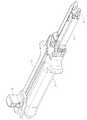
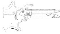
ここで、図面を参照すると、アンビル1、カートリッジ溝(Cartridge Channel)2、およびフックラッチ3から成る再利用可能なハンドルが示されている。図6および図7に描かれたアンビルの主な機能は、B形状ステープルの成形を可能にすることである。装置の発射の際に、カートリッジ小組立体(cartridge subassembly)から押し出されるU字型のステープルは、アンビルのステープル成形ポケット18に押し入れられ、その結果、B形状となる。アンビルはまた、装置が閉じられるのを可能にする円柱状突起部12a、12bも含む。これらの突起部は、フックラッチ3のカム面13a、13bと相互に作用し、アンビル面とカートリッジ面との間で組織を圧迫する。アンビルはまた、2つのV字型ノッチ17a、17bも含み、これらは、カートリッジ溝の突起部20と相互に作用し、使用中に、再利用可能な2つの部品を容易に整列させる手段を提供する。開示されるアンビルは、好ましくは、構造上の補足的な強度において役に立つよう、金属の単一ピースから作られる。さまざまな領域が個別に製造され、溶接などの既知の接合方法によって相互に取り付けられ得る。アンビルの組織ストッパー14a、14bは、ステープル留めされない組織の切開を防止するために、含まれる。Detailed Description of the Invention
Referring now to the drawings, a reusable handle consisting of an
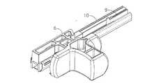
カートリッジ溝2は、使い捨てカートリッジを所定の場所に設置し、保持する。使用の際、溝のノッチ23a、23bは、カートリッジ組立体の突起部27a、27bにゆるやかに係合する。溝はまた、アンビル突起部12a、12bとの連結(interface)を可能にするように整列スロット16a、16bも含む。カートリッジ溝は、ノッチ24a、24bをも含み、ナイフモジュール5の保護キャップ7との、スナップ38a、38bを利用したスナップ接続を可能にする。溝はまた、近位端部に保持特徴部25を有し、モジュールパン10の戻り止め隆起部36a、36bとのスナップ接続を容易にする。 The cartridge groove 2 installs and holds a disposable cartridge in a predetermined place. In use, the groove notches 23a, 23b gently engage the protrusions 27a, 27b of the cartridge assembly. The groove also includes
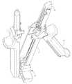
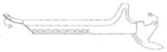
フックラッチ3は、スロット31によって、カートリッジ溝に取り外し可能に接続される。この取り外し可能な設計により、再利用可能な部品の容易な洗浄および滅菌が促進される。スロット31は、狭幅の開口を有し、この狭幅の開口よりわずかに大きい円形孔で終端をなす。フックラッチは、概して円柱形のピン上に2つの平坦部50a、50bを有するラッチピンを含む。図5aに示されるように、平坦部が溝スロット31に対して角度を定められると、溝スロット31内へのフックラッチの挿入が可能となる。次に、フックラッチは作動位置に回転され、この位置では、フックラッチは溝から外れることができない。 The
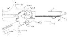
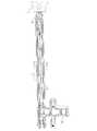
重要な点として、フックラッチの組立位置は、フックラッチの作動位置とは異なっており、作動中にフックラッチが外れるのを防止することを特筆する。図5a、図5bおよび図5cは、使用前の準備の際における、フックラッチのさまざまな位置を示す。図5eは、使用中における、開放位置にある装置を示す。この位置では、アンビルピン12a、12bは、溝スロット16a、16bから自由に外れることができる。一旦、組織が適切に配されると、装置は閉鎖前位置(pre-close position)に設定され、閉鎖を完了する前に組織の操作ができるようになっている。こうした別々の位置は、フックラッチのバネ手段34a、34bと、溝の戻り止め隆起部22との間の相互作用によって可能となる。図5dは、フックラッチのカム面13a、13bが溝スロット16a、16bを塞ぐことによって、アンビルピン12a、12bが溝スロットから外れるのを防止している、閉鎖前位置を示す。 It is important to note that the hook latch assembly position is different from the hook latch operating position and prevents the hook latch from being removed during operation. Figures 5a, 5b and 5c show the various positions of the hook latch during preparation before use. FIG. 5e shows the device in the open position when in use. In this position, the
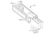
発射モジュール5は、発射機構を提供し、装置のジョー部に把持された組織のステープル留めおよび切開を可能にする。このモジュールは、洗浄が困難なことから、単一患者用の滅菌装置であることが好ましい。しかしながら、処置に対する費用削減のため、このモジュールは、同一患者において、複数回使用されることもできる。主な部品は、発射ノブ6、保護キャップ7、スペーサー8、ナイフ9、ウェッジ37a、37b、およびモジュールパン10である。モジュールパン10は、概してU字型をしており、残りの他の部品を合せて支持する構造を提供する。モジュールパン10はまた、2つの一体型の板バネをも含む。遠位端部のバネ52は、安全なロックアウト機構を作動させるよう使用され、この安全なロックアウト機構は、スペーサーに対してナイフを持ち上げ、使用済みカートリッジの再発射を防止する。図4bおよび図4cに示されるもう一方の板バネ11は、戻り止めバネとして作用する。戻り止めバネ11は、発射ノブのノッチと相互作用して配送中における発射ノブの前進移動を防止し、また、ノブが完全に戻った時に可聴フィードバックおよび触感によるフィードバックを提供する。ナイフおよびウェッジは、発射ノブに取り付けられ、使用の際、発射ノブによって押される。ナイフは、ナイフの特徴部40、41によって発射ノブに対しスライド可能に圧迫(constrained)される。ナイフは、研磨されたカッティングエッジを備えたシートメタル部品である。 The
再利用可能な装置(アンビル1、カートリッジ溝2、およびフックラッチ3を含む)は、非滅菌パッケージで使用者に提供される。使用者は、各処置の前に装置を滅菌するために、PH中性の酵素洗剤で、次に、高圧蒸気滅菌器(steam autoclave)で、装置を洗浄しなければならない。ナイフモジュール5は、滅菌された使い捨てパッケージに梱包される。使用者は、モジュールを滅菌野(sterile field)で開封する。カートリッジ4は、滅菌された使い捨てパッケージに梱包される。使用者は、カートリッジを滅菌野でパッケージから取り出す。ナイフモジュール5は、近位端部が最初に溝2に挿入され、所定の位置でスナップ止めされる。次に、モジュールの遠位端部が、溝内に入るよう下方に回転される。保護キャップ7は、モジュールを溝にロックするよう下方に押され、これにより、モジュールが所定の位置に保持される。次にフックラッチが溝内に挿入され、図5a、図5bおよび図5cに示されるように使用位置にロックされる。保護キャップは、キャップ7に埋め込まれた矢印の方向に保護キャップを動かすことによって外される。次に、新しいカートリッジが所定の位置に挿入される。図2は、カートリッジ4が、溝2内で、組立てられた位置にある状態を示す。横に切開されるべき組織が、アンビル1とカートリッジ4との間に配される。次に、フックラッチを図1に示される閉鎖位置に回転させることにより、装置が閉鎖される。この状態で、組織は、装置に把持される。アンビルの組織ストッパー14a、14bが、組織が装置内に入り込みすぎて配されるのを防止する。図5eに示される閉鎖前位置は、閉鎖を完了する前に組織を再配置するために使用され得る。この位置で、アンビルおよびカートリッジ溝は、互いにロックされるが、組織の再配置を調整するには十分に動くことができる。装置は、ノブが停止するまでノブを前方に押すことによって、発射される。この動作が、装置内に配された組織をステープル留めし、切り離す。ノブは、完全に戻った位置まで戻される。装置は、モジュールパン10の戻り止めバネの動作によって、触感によるフィードバックを提供する。ラッチは、開放位置に開かれる。使用済みカートリッジは、取り外され、廃棄される。必要であれば、新しいカートリッジが挿入され、装置が再利用される。一旦、必要な全ての組織が横に切開されると、フックラッチが、図5a、図5bに示される組立/取り外し可能位置に回転されることによって、外され、装置を洗浄および滅菌する準備がなされる。ナイフモジュールは、取り外され、廃棄される。次に、装置は、簡単な洗浄が促進されるよう、個々の部品として洗浄および滅菌される。こうして、装置の再利用の準備が整う。 Reusable devices (including
本発明は、いくつかの実施形態の記載によって説明されてきたが、そうした詳細内容に、添付の特許請求の範囲の精神および範囲を制限または限定することは、出願人の意図するところではない。本発明の範囲を逸脱することなく、多くの変更、変形および代用が、当業者には発想されるであろう。さらに、本発明に関連する各要素の構造は、その要素によって実施される機能を提供する手段として代替的に記載されることができる。従って、本発明は、添付の特許請求の範囲の精神および範囲によってのみ限定されることが意図されている。 While this invention has been described in terms of several embodiments, it is not the intention of the applicant to limit or limit the spirit and scope of the appended claims to such details. Many modifications, variations and substitutions will occur to those skilled in the art without departing from the scope of the invention. Further, the structure of each element associated with the present invention can alternatively be described as a means for providing the function performed by that element. Accordingly, it is intended that the invention be limited only by the spirit and scope of the appended claims.
〔実施の態様〕
(1)ステープルを組織中に配するための外科用ステープラーにおいて、
a.遠位端部、近位端部、および、前記遠位端部と前記近位端部との間の長さ方向軸を有する本体であって、前記近位端部はハンドルを含み、また、前記遠位端部はステープルカートリッジホルダーおよび反対側のアンビルを含む、本体と、
b.ステープルを配するためのアクチュエーターモジュールであって、前記アクチュエーターモジュールは、前記アンビルに向けてステープルを連続的に押し出すための、長さ方向に移動可能な部材を含み、前記アクチュエーターは、前記本体から容易に取り外されることができ、また、取り替えられ得る、アクチュエーターモジュールと、
を含む、外科用ステープラー。
(2)実施態様1に記載の外科用ステープラーにおいて、
複数のステープルを含んだステープルカートリッジであって、前記ステープルカートリッジは、前記ステープルカートリッジホルダー内に配される、ステープルカートリッジ、
をさらに含む、外科用ステープラー。Embodiment
(1) In a surgical stapler for placing staples in tissue,
a. A body having a distal end, a proximal end, and a longitudinal axis between the distal end and the proximal end, the proximal end including a handle; and The distal end includes a body including a staple cartridge holder and an opposite anvil;
b. An actuator module for dispensing staples, the actuator module including a longitudinally movable member for continuously pushing staples toward the anvil, the actuator being easily accessible from the body An actuator module that can be removed and replaced
Including surgical stapler.
(2) In the surgical stapler according to
A staple cartridge comprising a plurality of staples, wherein the staple cartridge is disposed within the staple cartridge holder;
A surgical stapler further comprising:
Claims (13)
Translated fromJapanesea.遠位端部、近位端部、および、前記遠位端部と前記近位端部との間の長さ方向軸を有する本体であって、前記近位端部はハンドルおよび近位溝を含み、また、前記遠位端部はステープルカートリッジ溝および反対側のアンビルを含む、本体と、
b.ステープルを配するための発射モジュールであって、前記発射モジュールは、前記アンビルに向けてステープルを連続的に押し出すための、少なくとも1つの、長さ方向に移動可能な部材を含み、前記発射モジュールは、前記近位溝の中に前記発射モジュールを取り外し可能に取り付けるための取り付け手段を有するモジュールパンをさらに含む、発射モジュールと、
を含み、
前記モジュールパンは、U字型の断面を有し、その中に前記長さ方向に移動可能な部材を支持し、
前記取り付け手段は、前記近位溝の近位端部に設けられた保持特徴部とのスナップ接続を可能にする、前記モジュールパンの外面に設けられた戻り止め隆起部を含み、
前記発射モジュールは、前記発射モジュールを前記近位溝内の所定の位置に保持するための、前記本体に設けられたノッチとのスナップ接続を可能にする保護キャップをさらに含む、外科用ステープラー。In a surgical stapler for placing staples in tissue,
a. A body having a distal end, a proximal end, and a longitudinal axis between the distal end and the proximal end, wherein the proximal end includes a handle and a proximal groove. A body, wherein the distal end includes a staple cartridge groove and an opposite anvil;
b. Afiring module for deploying staples, saidfiring module, for sequentially ejecting staples towards the anvil, comprises at least one, longitudinally movable member, saidfiring module , further comprising a module pan having an attachment means for removably attaching saidfiring module into the proximal groove, afiring module,
Only including,
The module pan has a U-shaped cross section, and supports a member movable in the length direction therein,
The attachment means includes a detent ridge provided on an outer surface of the module pan that allows a snap connection with a retention feature provided at a proximal end of the proximal groove;
The surgical stapler, wherein the firing module further includes a protective cap that allows a snap connection with a notch provided in the body to hold the firing module in place within the proximal groove .
複数のステープルを含んだステープルカートリッジであって、前記ステープルカートリッジは、前記ステープルカートリッジ溝内に配される、ステープルカートリッジ、
をさらに含む、外科用ステープラー。The surgical stapler according to claim 1, wherein
A staple cartridge comprising a plurality of staples, wherein the staple cartridge is disposed in the staple cartridge groove;
A surgical stapler further comprising:
前記本体は、上側ジョー部、および下側ジョー部を含み、前記上側および下側ジョー部は各々、単一部品として形成されており、前記上側ジョー部は、対になった固定用突起部を有し、前記下側ジョー部は、対になった整列スロットを含み、前記突起部は、前記スロットの中に挿入されて前記上側および下側ジョー部を整列させる、外科用ステープラー。The surgical stapler according to claim 2, wherein
The main body includes an upper jaw portion and a lower jaw portion, and each of the upper and lower jaw portions is formed as a single part, and the upper jaw portion includes a pair of fixing protrusions. A surgical stapler, wherein the lower jaw includes a pair of aligned slots and the protrusion is inserted into the slot to align the upper and lower jaws.
前記本体の前記長さ方向軸に沿った中間の位置で前記上側および下側ジョー部を共に接続するためのラッチ部材、
をさらに含み、
前記ラッチ部材は、前記上側および下側ジョー部に対して移動可能である、外科用ステープラー。The surgical stapler according to claim3 ,
Latch member for both connecting the upper and lower jaws at an intermediate position along said longitudinal axis of said body,
Further including
Thelatch member is movable relative to the upper and lower jaws, a surgical stapler.
前記ラッチ部材は、前記ステープラーを一連の異なるロック状態に位置づけるように、前記上側および下側ジョー部に対して移動可能である、外科用ステープラー。The surgical stapler according to claim4 , wherein
Thelatch member is to position the stapler in a series of different locking states, it is movable relative to said upper and lower jaws, a surgical stapler.
前記ラッチ部材は、単一部品コンポーネントであり、前記上側ジョー部、前記下側ジョー部、および前記ラッチ部材は、前記ステープラーから取り外され、異なる患者の手技で再利用するために洗浄および滅菌されることができる、外科用ステープラー。The surgical stapler according to claim4 , wherein
Thelatch member is a single piece component,washing the upper jaw portion, the lower jaw portion, and thelatch member is removed from the stapler, in order to reuse in a different patient procedures Surgical stapler that can besterilized and .
前記ラッチ部材は、ラッチピンを含み、前記ラッチピンは、前記ステープラーに対して前記ラッチ部材を接続したり接続解除したりするために、前記本体上のスロットに挿入および取り外し可能である、外科用ステープラー。The surgical stapler according to claim4 , wherein
Thelatch member includes a latch pin, said latch pin, to or disconnect or connect thelatch member relative to the stapler, it is inserted and removably slot on the body, Surgical stapler.
前記本体は、前記上側および下側ジョー部に対して前記異なるロック状態に前記ラッチ部材を保持するための、前記本体上に設けられた戻り止め部をさらに含む、外科用ステープラー。The surgical stapler according to claim5 , wherein
Said body, said upper and lower jaw for holding thelatch member in the different lock state with respect to unit, further comprising a detent portion provided on the body, the surgical stapler.
前記戻り止め部は、前記ラッチ部材をロック閉鎖前状態に保持することができ、前記ロック閉鎖前状態では、前記上側ジョー部の突起部が、前記下側ジョー部のスロットから係合解除されるのを妨げられ、前記下側ジョー部は、なお前記上側ジョー部に対して動くことができる、外科用ステープラー。The surgical stapler according to claim8 ,
The detent portion, the rack can holdswitch member in the locked closed state before, in the locked closed state before the protrusion of the upper jaw portion, disengaged from the lower jaw of the slot Surgical stapler that is prevented from being moved and the lower jaw portion can still move relative to the upper jaw portion.
前記戻り止め部は、前記ラッチ部材を部分的にロックされた状態に保持することができ、前記部分的にロックされた状態では、前記ラッチ部材が、前記下側ジョー部に接続されており、前記上側ジョー部の突起部は、前記下側ジョー部のスロットから係合解除されて、前記上側および下側ジョー部が分離されるのを可能にする、外科用ステープラー。The surgical stapler according to claim8 ,
The detent portion, saidlatch member partially can be held in a locked state, in the partly locked state, thelatch member is connected to the lower jaw portion A surgical stapler, wherein the protrusion of the upper jaw portion is disengaged from the slot of the lower jaw portion to allow the upper and lower jaw portions to be separated.
前記ラッチ部材は、前記下側ジョー部の対向する側壁に対して移動可能であるフックラッチをさらに含み、前記フックラッチは、ロック閉鎖状態で前記上側ジョー部の突起部に係合し、前記上側および下側ジョー部を共に作動位置に固定する、外科用ステープラー。The surgical stapler according to claim 7, wherein
Thelatch member further includes a hook latch is movable relative to opposite side walls of the lower jaw portion, the hook latch is engaged with the protrusion of the upper jaw portion in the locked closed state, A surgical stapler that secures the upper and lower jaws together in an operating position.
前記本体は、ステープルカートリッジを前記本体に接続したり接続解除したりするためのノッチをさらに含み、
複数のステープルカートリッジが、前記本体の内部で単一の発射モジュールと共に使用され得る、外科用ステープラー。The surgical stapler according to claim3 ,
The body further includes a notch for connecting and disconnecting a staple cartridge to and from the body,
A surgical stapler, wherein a plurality of staple cartridges can be used with a singlefiring module within the body.
前記長さ方向に移動可能な部材は、ナイフおよび対になったウェッジを含む、外科用ステープラー。The surgical stapler according to claim 1, wherein
The surgical stapler, wherein the longitudinally movable member includes a knife and a pair of wedges.
Applications Claiming Priority (2)
| Application Number | Priority Date | Filing Date | Title |
|---|---|---|---|
| US77816407A | 2007-07-16 | 2007-07-16 | |
| US11/778,164 | 2007-07-16 |
Publications (2)
| Publication Number | Publication Date |
|---|---|
| JP2009066392A JP2009066392A (en) | 2009-04-02 |
| JP5683775B2true JP5683775B2 (en) | 2015-03-11 |
Family
ID=40010761
Family Applications (1)
| Application Number | Title | Priority Date | Filing Date |
|---|---|---|---|
| JP2008183388AActiveJP5683775B2 (en) | 2007-07-16 | 2008-07-15 | Partially reusable surgical stapler |
Country Status (4)
| Country | Link |
|---|---|
| EP (1) | EP2018826B1 (en) |
| JP (1) | JP5683775B2 (en) |
| CN (1) | CN101366647B (en) |
| PL (1) | PL2018826T3 (en) |
Families Citing this family (16)
| Publication number | Priority date | Publication date | Assignee | Title |
|---|---|---|---|---|
| US8308043B2 (en)* | 2009-05-19 | 2012-11-13 | Covidien Lp | Recognition of interchangeable component of a device |
| BR112013007627B1 (en)* | 2010-09-30 | 2021-01-05 | Ethicon Endo-Surgery, Inc | surgical stapling system |
| CN101991452B (en) | 2010-12-10 | 2012-07-04 | 苏州天臣国际医疗科技有限公司 | Linear type surgical stapling apparatus |
| US8714352B2 (en) | 2010-12-10 | 2014-05-06 | Covidien Lp | Cartridge shipping aid |
| US9451959B2 (en) | 2011-06-09 | 2016-09-27 | Covidien Lp | Surgical fastener applying apparatus |
| US9271728B2 (en) | 2011-06-09 | 2016-03-01 | Covidien Lp | Surgical fastener applying apparatus |
| US9724095B2 (en) | 2011-08-08 | 2017-08-08 | Covidien Lp | Surgical fastener applying apparatus |
| CN102429693B (en)* | 2011-12-14 | 2013-05-29 | 北京中法派尔特医疗设备有限公司 | A staple cartridge assembly of a linear cutting stapler and a stapler using the same |
| CN105682567B (en) | 2013-11-04 | 2021-09-10 | 柯惠Lp公司 | Surgical fastener applying apparatus |
| CN105682568B (en) | 2013-11-04 | 2018-10-23 | 柯惠Lp公司 | Surgical fasteners bringing device |
| US10175127B2 (en)* | 2014-05-05 | 2019-01-08 | Covidien Lp | End-effector force measurement drive circuit |
| US11039832B2 (en) | 2015-08-24 | 2021-06-22 | Cilag Gmbh International | Surgical stapler buttress applicator with spent staple cartridge lockout |
| US10166023B2 (en) | 2015-08-24 | 2019-01-01 | Ethicon Llc | Method of applying a buttress to a surgical stapler end effector |
| US10342532B2 (en)* | 2015-08-24 | 2019-07-09 | Ethicon Llc | Surgical stapler buttress applicator with multi-point actuated release mechanism |
| US11033266B2 (en)* | 2018-08-13 | 2021-06-15 | Cilag Gmbh International | Decoupling mechanism for linear surgical stapler |
| US10898187B2 (en) | 2018-08-13 | 2021-01-26 | Ethicon Llc | Firing system for linear surgical stapler |
Family Cites Families (9)
| Publication number | Priority date | Publication date | Assignee | Title |
|---|---|---|---|---|
| AU534210B2 (en)* | 1980-02-05 | 1984-01-12 | United States Surgical Corporation | Surgical staples |
| US4633861A (en) | 1984-10-19 | 1987-01-06 | Senmed, Inc. | Surgical stapling instrument with jaw clamping mechanism |
| US4633874A (en) | 1984-10-19 | 1987-01-06 | Senmed, Inc. | Surgical stapling instrument with jaw latching mechanism and disposable staple cartridge |
| US5129570A (en) | 1990-11-30 | 1992-07-14 | Ethicon, Inc. | Surgical stapler |
| US5931847A (en)* | 1997-01-09 | 1999-08-03 | Ethicon Endo-Surgery, Inc. | Surgical cutting instrument with improved cutting edge |
| US5865361A (en)* | 1997-09-23 | 1999-02-02 | United States Surgical Corporation | Surgical stapling apparatus |
| AU2003230359B2 (en)* | 2002-05-10 | 2008-11-13 | Covidien Lp | Electrosurgical stapling apparatus |
| CN2577769Y (en)* | 2002-11-13 | 2003-10-08 | 马剑文 | side stapler |
| US7398908B2 (en)* | 2005-08-15 | 2008-07-15 | Tyco Healthcare Group Lp | Surgical stapling instruments including a cartridge having multiple staple sizes |
- 2008
- 2008-07-15JPJP2008183388Apatent/JP5683775B2/enactiveActive
- 2008-07-16PLPL08252413.3Tpatent/PL2018826T3/enunknown
- 2008-07-16EPEP08252413.3Apatent/EP2018826B1/enactiveActive
- 2008-07-16CNCN2008101316129Apatent/CN101366647B/enactiveActive
Also Published As
| Publication number | Publication date |
|---|---|
| PL2018826T3 (en) | 2016-10-31 |
| CN101366647B (en) | 2013-03-27 |
| EP2018826A3 (en) | 2009-09-16 |
| JP2009066392A (en) | 2009-04-02 |
| EP2018826A2 (en) | 2009-01-28 |
| CN101366647A (en) | 2009-02-18 |
| EP2018826B1 (en) | 2016-04-13 |
Similar Documents
| Publication | Publication Date | Title |
|---|---|---|
| JP5683775B2 (en) | Partially reusable surgical stapler | |
| EP2299914B1 (en) | A partially reusable surgical stapler | |
| JP5512663B2 (en) | Partially reusable surgical stapler | |
| JP4722476B2 (en) | Surgical instruments adapted to staple and dissect tissue in a highly controlled form | |
| EP3187130B1 (en) | Surgical stapler with variable height drivers for uniform staple formation | |
| JP4731904B2 (en) | Surgical instruments adapted to staple and dissect tissue in a highly controlled form | |
| JP4704028B2 (en) | Surgical instruments adapted to apply multiple surgical fasteners to body tissue | |
| CN106974687B (en) | Surgical fastener applying apparatus | |
| CN110680437B (en) | Surgical fastener applying apparatus | |
| ES3035092T3 (en) | Features to enhance staple height consistency in curved surgical stapler | |
| AU2012294734A1 (en) | Surgical fastener applying apparatus | |
| JP2015506753A (en) | Surgical fastener applicator | |
| CN105682570A (en) | Surgical fastener applying apparatus | |
| JP5623392B2 (en) | Partially reusable surgical stapler | |
| JP2008188433A (en) | Surgical stapling apparatus with locking mechanism |
Legal Events
| Date | Code | Title | Description |
|---|---|---|---|
| RD04 | Notification of resignation of power of attorney | Free format text:JAPANESE INTERMEDIATE CODE: A7424 Effective date:20100806 | |
| A621 | Written request for application examination | Free format text:JAPANESE INTERMEDIATE CODE: A621 Effective date:20110715 | |
| RD04 | Notification of resignation of power of attorney | Free format text:JAPANESE INTERMEDIATE CODE: A7424 Effective date:20111209 | |
| A977 | Report on retrieval | Free format text:JAPANESE INTERMEDIATE CODE: A971007 Effective date:20130117 | |
| A131 | Notification of reasons for refusal | Free format text:JAPANESE INTERMEDIATE CODE: A131 Effective date:20130122 | |
| A521 | Request for written amendment filed | Free format text:JAPANESE INTERMEDIATE CODE: A523 Effective date:20130405 | |
| A02 | Decision of refusal | Free format text:JAPANESE INTERMEDIATE CODE: A02 Effective date:20131022 | |
| A521 | Request for written amendment filed | Free format text:JAPANESE INTERMEDIATE CODE: A523 Effective date:20140220 | |
| A911 | Transfer to examiner for re-examination before appeal (zenchi) | Free format text:JAPANESE INTERMEDIATE CODE: A911 Effective date:20140228 | |
| A912 | Re-examination (zenchi) completed and case transferred to appeal board | Free format text:JAPANESE INTERMEDIATE CODE: A912 Effective date:20140502 | |
| A61 | First payment of annual fees (during grant procedure) | Free format text:JAPANESE INTERMEDIATE CODE: A61 Effective date:20150114 | |
| R150 | Certificate of patent or registration of utility model | Ref document number:5683775 Country of ref document:JP Free format text:JAPANESE INTERMEDIATE CODE: R150 | |
| R250 | Receipt of annual fees | Free format text:JAPANESE INTERMEDIATE CODE: R250 | |
| R250 | Receipt of annual fees | Free format text:JAPANESE INTERMEDIATE CODE: R250 | |
| R250 | Receipt of annual fees | Free format text:JAPANESE INTERMEDIATE CODE: R250 | |
| R250 | Receipt of annual fees | Free format text:JAPANESE INTERMEDIATE CODE: R250 | |
| R250 | Receipt of annual fees | Free format text:JAPANESE INTERMEDIATE CODE: R250 | |
| R250 | Receipt of annual fees | Free format text:JAPANESE INTERMEDIATE CODE: R250 | |
| R250 | Receipt of annual fees | Free format text:JAPANESE INTERMEDIATE CODE: R250 | |
| R250 | Receipt of annual fees | Free format text:JAPANESE INTERMEDIATE CODE: R250 |