JP5683102B2 - Lean delayed injection with adjustment of airflow division - Google Patents
Lean delayed injection with adjustment of airflow divisionDownload PDFInfo
- Publication number
- JP5683102B2 JP5683102B2JP2009296996AJP2009296996AJP5683102B2JP 5683102 B2JP5683102 B2JP 5683102B2JP 2009296996 AJP2009296996 AJP 2009296996AJP 2009296996 AJP2009296996 AJP 2009296996AJP 5683102 B2JP5683102 B2JP 5683102B2
- Authority
- JP
- Japan
- Prior art keywords
- fuel
- combustor
- transition zone
- compressor
- turbine
- Prior art date
- Legal status (The legal status is an assumption and is not a legal conclusion. Google has not performed a legal analysis and makes no representation as to the accuracy of the status listed.)
- Expired - Fee Related
Links
- 238000002347injectionMethods0.000titledescription7
- 239000007924injectionSubstances0.000titledescription7
- 230000003111delayed effectEffects0.000titledescription2
- 239000000446fuelSubstances0.000claimsdescription182
- 230000007704transitionEffects0.000claimsdescription70
- 238000002485combustion reactionMethods0.000claimsdescription23
- 238000000034methodMethods0.000claimsdescription19
- 239000012530fluidSubstances0.000claimsdescription4
- 230000003247decreasing effectEffects0.000claimsdescription2
- 239000007789gasSubstances0.000description32
- VNWKTOKETHGBQD-UHFFFAOYSA-NmethaneChemical compoundCVNWKTOKETHGBQD-UHFFFAOYSA-N0.000description24
- 239000003054catalystSubstances0.000description7
- MWUXSHHQAYIFBG-UHFFFAOYSA-Nnitrogen oxideInorganic materialsO=[N]MWUXSHHQAYIFBG-UHFFFAOYSA-N0.000description6
- 239000000203mixtureSubstances0.000description5
- 239000003345natural gasSubstances0.000description4
- 230000003647oxidationEffects0.000description4
- 238000007254oxidation reactionMethods0.000description4
- 238000009792diffusion processMethods0.000description3
- 238000010790dilutionMethods0.000description3
- 239000012895dilutionSubstances0.000description3
- 229930195733hydrocarbonNatural products0.000description3
- 150000002430hydrocarbonsChemical class0.000description3
- 230000009257reactivityEffects0.000description3
- ATUOYWHBWRKTHZ-UHFFFAOYSA-NPropaneChemical compoundCCCATUOYWHBWRKTHZ-UHFFFAOYSA-N0.000description2
- 239000001273butaneSubstances0.000description2
- 239000001257hydrogenSubstances0.000description2
- 229910052739hydrogenInorganic materials0.000description2
- 125000004435hydrogen atomChemical class[H]*0.000description2
- IJDNQMDRQITEOD-UHFFFAOYSA-Nn-butaneChemical compoundCCCCIJDNQMDRQITEOD-UHFFFAOYSA-N0.000description2
- OFBQJSOFQDEBGM-UHFFFAOYSA-Nn-pentaneNatural productsCCCCCOFBQJSOFQDEBGM-UHFFFAOYSA-N0.000description2
- 238000010926purgeMethods0.000description2
- 239000000376reactantSubstances0.000description2
- IJGRMHOSHXDMSA-UHFFFAOYSA-NAtomic nitrogenChemical compoundN#NIJGRMHOSHXDMSA-UHFFFAOYSA-N0.000description1
- 239000004215Carbon black (E152)Substances0.000description1
- UGFAIRIUMAVXCW-UHFFFAOYSA-NCarbon monoxideChemical compound[O+]#[C-]UGFAIRIUMAVXCW-UHFFFAOYSA-N0.000description1
- 101100322735Danio rerio aep1 geneProteins0.000description1
- OTMSDBZUPAUEDD-UHFFFAOYSA-NEthaneChemical compoundCCOTMSDBZUPAUEDD-UHFFFAOYSA-N0.000description1
- 101100310354Homo sapiens SKIDA1 geneProteins0.000description1
- 101150042946NAC20 geneProteins0.000description1
- 102100027349SKI/DACH domain-containing protein 1Human genes0.000description1
- 239000000809air pollutantSubstances0.000description1
- 231100001243air pollutantToxicity0.000description1
- 238000003915air pollutionMethods0.000description1
- 230000004075alterationEffects0.000description1
- 230000015572biosynthetic processEffects0.000description1
- 229910002091carbon monoxideInorganic materials0.000description1
- 230000003197catalytic effectEffects0.000description1
- 238000006243chemical reactionMethods0.000description1
- 238000001816coolingMethods0.000description1
- 230000000694effectsEffects0.000description1
- 230000007613environmental effectEffects0.000description1
- 230000009970fire resistant effectEffects0.000description1
- 239000002737fuel gasSubstances0.000description1
- 238000002309gasificationMethods0.000description1
- 238000004519manufacturing processMethods0.000description1
- 230000004048modificationEffects0.000description1
- 238000012986modificationMethods0.000description1
- 239000001294propaneSubstances0.000description1
- 238000006467substitution reactionMethods0.000description1
Images


Classifications
- F—MECHANICAL ENGINEERING; LIGHTING; HEATING; WEAPONS; BLASTING
- F02—COMBUSTION ENGINES; HOT-GAS OR COMBUSTION-PRODUCT ENGINE PLANTS
- F02C—GAS-TURBINE PLANTS; AIR INTAKES FOR JET-PROPULSION PLANTS; CONTROLLING FUEL SUPPLY IN AIR-BREATHING JET-PROPULSION PLANTS
- F02C7/00—Features, components parts, details or accessories, not provided for in, or of interest apart form groups F02C1/00 - F02C6/00; Air intakes for jet-propulsion plants
- F02C7/22—Fuel supply systems
- F—MECHANICAL ENGINEERING; LIGHTING; HEATING; WEAPONS; BLASTING
- F23—COMBUSTION APPARATUS; COMBUSTION PROCESSES
- F23R—GENERATING COMBUSTION PRODUCTS OF HIGH PRESSURE OR HIGH VELOCITY, e.g. GAS-TURBINE COMBUSTION CHAMBERS
- F23R3/00—Continuous combustion chambers using liquid or gaseous fuel
- F23R3/28—Continuous combustion chambers using liquid or gaseous fuel characterised by the fuel supply
- F23R3/34—Feeding into different combustion zones
- F—MECHANICAL ENGINEERING; LIGHTING; HEATING; WEAPONS; BLASTING
- F23—COMBUSTION APPARATUS; COMBUSTION PROCESSES
- F23N—REGULATING OR CONTROLLING COMBUSTION
- F23N2241/00—Applications
- F23N2241/20—Gas turbines
Landscapes
- Engineering & Computer Science (AREA)
- Chemical & Material Sciences (AREA)
- Combustion & Propulsion (AREA)
- Mechanical Engineering (AREA)
- General Engineering & Computer Science (AREA)
- Output Control And Ontrol Of Special Type Engine (AREA)
Description
Translated fromJapanese本発明は、希薄遅延噴射(LLI)燃料のステージング及び希薄遅延噴射の方法に関する。 The present invention relates to lean retarded injection (LLI) fuel staging and lean retarded injection methods.
現在、一部のガスタービンエンジンでは、非効率的な動作により、望ましくない空気汚染物質が排出される。従来の炭化水素燃料を燃焼させるタービンから発生する主な空気汚染排出物は、基本的に、窒素酸化物、一酸化炭素及び未燃焼炭化水素である。ガスタービンエンジンにおける、例えば窒素分子の酸化は、燃焼器内の高温、及び反応物が燃焼器内で高温になる時間の長さの影響を受けて進行する。従って、燃焼器温度をサーマルNOx形成レベルよりも低く保つことによって、又は、反応物が高温になる時間を制限し、NOxが形成される時間的猶予を与えないことによって、サーマルNOxを低減させる。 Currently, some gas turbine engines emit undesirable air pollutants due to inefficient operation. The main air pollution emissions generated from turbines that burn conventional hydrocarbon fuels are basically nitrogen oxides, carbon monoxide and unburned hydrocarbons. In gas turbine engines, for example, the oxidation of molecular nitrogen proceeds under the influence of the high temperature in the combustor and the length of time that the reactants are hot in the combustor. Therefore, thermal NOx is reduced by keeping the combustor temperature below the thermal NOx formation level, or by limiting the time during which the reactants become hot and not giving time to form NOx.
温度制御の一方法には、燃焼前に燃料と空気を予混合して、希薄混合気を生成することが含まれる。しかしながら、大型の産業用ガスタービンの場合、予混合希薄燃料を使用しても、燃焼生成物に必要な温度が非常に高いので、燃焼器の反応ゾーン内をサーマルNOxが形成される温度閾値を上回るピークガス温度となるよう動作させることになる。その結果、多量のNOxが形成される。One method of temperature control includes premixing fuel and air before combustion to produce a lean mixture. However, in the case of large industrial gas turbines, even if premixed lean fuel is used, the temperature required for the combustion products is very high, so the temperature threshold at which thermal NOx is formed in the reactionzone of the combustor. It will be operated to have a peak gas temperature above. As a result, a large amount of NOx is formed.
本発明の一実施形態に係るガスタービンエンジンは、燃料回路から供給される第1の燃料を燃焼させる第1の内部空間を有する燃焼器と、回転タービンブレードを有するタービンであって、少なくとも第1の燃料の燃焼生成物を受け取ってタービンブレードに回転力を与えるタービンと、燃料回路から供給される第2の燃料と第1の燃料の燃焼生成物とを燃焼させることのできる第2の内部空間を含む移行ゾーンであって、燃焼器とタービンとを互いに流体接続させる移行ゾーンと、移行ゾーンによって構造的に支持され、燃料回路に接続された複数の燃料噴射器であって、第2の燃料を第2の内部空間に軸方向単段、軸方向多段、軸方向単段周方向段及び軸方向多段周方向段のいずれかで供給するように構成された複数の燃料噴射器と、燃焼器及び移行ゾーンに流体接続された圧縮機であって、燃焼用の空気を第1及び第2の内部空間に供給する圧縮機と、燃料回路に接続された制御システムであって、第1及び第2の内部空間への空気の相対量、及び燃料回路から第1及び第2の内部空間に供給される第1及び第2の燃料の相対量を制御する制御システムとを備える。Gas turbine engine according to an embodiment of the present invention includes a combustor having afirst interiorspace combustingthe first fuelthat will be supplied from the fuel circuit, a turbine having a rotating turbine blade, at least a first internalcombustion products of fuelit receives a turbine which gives a rotational force to the turbine blade,the secondthat will be supplied from the fuel circuit fuel anda secondthat can be combusted and the combustion productsof the first fuel a transitionzone including aspace, a transitionzone Ru is fluidly connected to each othercombustorand a turbine, is structurally supported by the transitionzone, a plurality of fuel injectors connected to the fuel circuit, the secondaxialsingle stage in the innerspaceof the fuelsecond, andmultipleaxialstages, a plurality of fuel injectors configured to supplyat eitheraxial singlestage circumferential stage andmultipleaxialstages circumferential stages, Burning A vessel and fluid-connectedcompressors inthe transitionzone,the air for combustion andcompressor suppliedto the first andsecond internalspaces, a connected control system to the fuel circuit, the first and the relative amounts of air intothe second internalspace, and a control system for controlling the first and the relative amountof the secondfuel from the fuel circuit Ruis supplied to thefirst andsecond internalspaces.
本発明の別の実施形態に係る、燃料回路から供給される第1の燃料を燃焼させる第1の内部空間を有する燃焼器と、回転タービンブレードを有するタービンであって、少なくとも第1の燃料の燃焼生成物を受け取ってタービンブレードに回転力を与えるタービンを備えたガスタービンエンジンは、燃料回路から供給される第2の燃料と第1の燃料の燃焼生成物とを燃焼させることのできる第2の内部空間を含む移行ゾーンであって、燃焼器とタービンとを互いに流体接続させる移行ゾーンと、移行ゾーンによって構造的に支持され、燃料回路に接続された複数の燃料噴射器であって、第2の燃料を第2の内部空間に軸方向単段、軸方向多段、軸方向単段周方向段及び軸方向多段周方向段のいずれかで供給するように構成された複数の燃料噴射器と、燃焼器及び移行ゾーンに流体接続された圧縮機であって、燃焼用の空気を第1及び第2の内部空間に供給する圧縮機と、燃料回路に接続された制御システムであって、第1及び第2の内部空間への空気の相対量、及び燃料回路から第1及び第2の内部空間に供給される第1及び第2の燃料の相対量を制御する制御システムとを備える。According to another embodiment of the present invention, a combustor having afirst interiorspace combustingthe first fuelthat will be supplied from the fuel circuit, a turbine having a rotating turbine blades, at least afirst fuel gas turbine engine having a turbine which gives a rotational force to the combustion products to the turbine blade receive the firstcapable of combusting the combustion products of thesecond fuel andthe first fuelthat will be supplied from the fuel circuit a transitionzone comprising twointernalspaces, the transitionzone Ru is fluidly connected to each othercombustorand a turbine, is structurally supported by the transitionzone, a plurality of fuel injectors connected to the fuel circuit ,singleaxialstage thesecond fuelsecond internalspace,multipleaxialstages, a plurality of fuel injection that is configured to provideeither a singleaxialstage circumferential stage andmultipleaxialstages circumferential stage When, a combustor and fluid connected tothe compressor tothe transitionzone,the air for combustion andcompressor suppliedto the first andsecond internalspaces, a connected control system to the fuel circuit, the relative amounts of air into the first andsecond internalspace, and a control system for controlling the first and the relative amountof the secondfuel from the fuel circuit Ruis supplied to thefirst andsecond internalspaces.
本発明の更に別の実施形態に係る、タービンが燃焼器に、両者間の移行ゾーンを介して流体接続されており、空気が圧縮機から燃焼器及び移行ゾーンに供給されるガスタービンエンジンの動作方法は、第1の燃料を燃焼器の第1の内部空間に供給すること、第1の燃料を燃焼器の第1の内部空間で燃焼させること、第2の燃料を第2の内部空間に軸方向単段、軸方向多段、軸方向単段周方向段及び軸方向多段周方向段のいずれかで供給すること、第2の燃料と第1の内部空間から受け取った燃焼生成物の流れとを移行ゾーンの第2の内部空間で燃焼させること、並びに、空気と第1及び第2の内部空間に供給される第1及び第2の燃料との相対量を制御することを含む。Operation of a gas turbine engine in which a turbine is fluidly connected to a combustor via a transitionzone between the two and air is supplied from thecompressor to the combustor and the transitionzone according to yet another embodiment of the present invention. the method comprises providing afirst fuel toa first interiorspace of the combustor, combusting the firstfuel in thefirst interiorspace of the combustor, asecond fuel to thesecond interiorspace asingleaxialstage,multipleaxialstages, be providedin eitheraxial singlestage circumferential stage andmultipleaxialstages circumferential stages, the flow of combustion products, received from thesecond fuel andthe first internalspace It is burned inthe second internalspace of the transitionzone, and comprises controlling the relative amounts of air and the first andsecond fuelthat will be supplied to the first andsecond internalspaces.
添付図面に対応した以下の説明において、本発明による、以上に記載の及びその他の利点及び特徴が明示されている。 In the following description, corresponding to the accompanying drawings, the foregoing and other advantages and features of the invention will be apparent.
本発明の企図は、添付の特許請求の範囲に明記されている。次に、本発明による、以上に記載の及びその他の利点及び特徴の詳細な説明と対応した添付図面の内容を説明する。 The intention of the invention is specified in the appended claims. Reference will now be made to the content of the accompanying drawings, which correspond to the detailed description of the foregoing and other advantages and features of the invention.
以下、添付図面を参照しながら本発明の実施例、利点及び特徴について詳細に説明する。Hereinafter , embodiments, advantages, and features of the present invention will be described in detail with reference to the accompanying drawings.
図1に示すガスタービンエンジン10は、燃料回路70から供給される第1の燃料を燃焼させる第1の内部空間21を有する燃焼器20と、吸気を圧縮して少なくとも燃焼器20及び移行ゾーン43に導入する圧縮機30と、回転タービンブレードを有するタービン50を備える。このタービン50は、少なくとも第1の燃料の燃焼生成物を受け取ってタービンブレードに回転力を与える。燃焼器とタービンは、移行ゾーン43を介して流体接続しており、移行ゾーン43には、燃料回路70から供給される第2の燃料と第1の燃料の燃焼生成物とを燃焼させることのできる第2の内部空間41が含まれる。図示のように、燃焼器20と移行ゾーン43は連通しており、全体としてヘッドエンド11を構成しているが、この構造は、後述するように様々であってよい。
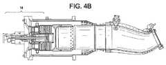
図1のように、ヘッドエンド11は、複数の予混合ノズル12を有してもよい。しかしながら、ヘッドエンド11は、図4A〜Dのようなその他の構造であってもよい。そのような代替構造には、例えば、図4Aの標準燃焼器13、図4Bの乾燥低NOx(DLN)1+燃焼器14、図4CのDLN2+燃焼器15及び図4DのDLN2.6/2.6+燃焼器16がある。更に別の燃焼器の構造としては、統合ガス化複合サイクル(IGCC)ヘッドエンド、触媒ヘッドエンド、拡散型ヘッドエンド、及び複数のノズル式静音燃焼(MNQC)ヘッドエンドがある。 As shown in FIG. 1, the
ヘッドエンド11の上記構造にはそれぞれ、希薄遅延噴射(LLI)を適用可能であることが理解できよう。LLIを行うには、燃焼器として、出口温度が2500°F超の任意の燃焼器を用いるか、メタンよりも反応性の高い成分を含有し、高温側滞留時間が10msを上回る燃料を用いる。例えば、DLN1+燃焼器14におけるLLIの場合、出口温度が2500°F未満であってもよいが、メタンよりも反応性が高い成分を含有する燃料を用いる。拡散式ヘッドエンド燃焼器におけるLLIの場合、出口温度を2500°F超とし、メタンよりも反応性が高い成分を含有する燃料を用いる。同様に、DLN2.0/DLN2+燃焼器15におけるLLIの場合、出口温度を2500°F超とし、メタンよりも反応性が高い成分を含有する燃料を用い、触媒ヘッドエンド又はDLN2.6/2.6+燃焼器16におけるLLIの場合、出口温度を2500°F超とし、メタンよりも反応性が高い成分を含有する燃料を用いる。 It will be appreciated that lean retarded injection (LLI) can be applied to each of the above structures of the
移行ゾーン43の外壁、すなわち移行ゾーン43周囲のスリーブ40の外壁によって、複数の燃料噴射器60のそれぞれが構造的に支持されており、燃料噴射器60は、第2の内部空間41に任意の長さだけ延出している。この構造において、燃料噴射器60のそれぞれによって、LLI燃料のステージングが行われる。すなわち、燃料噴射器60はそれぞれ、第2の燃料(すなわちLLI燃料)を第2の内部空間41へ、例えば、移行ゾーン43を通る主流の方向にほぼ直交するように、且つ軸方向単段、軸方向多段、軸方向単段周方向段及び軸方向多段周方向段のいずれかで供給する。このとき、局所的な燃焼ゾーンを安定して形成するよう、燃焼器20と移行ゾーン43を各段に区切る。The outer wall of the
図5A〜Dのように、燃料噴射器60は、様々な特徴及び機能を有する。例えば、図5Aのように、燃料噴射器60は、チューブ・イン・チューブ(tube-in-tube)式の噴射器125を含む。この構造の場合、燃料は、チューブ130内のノズルから移行ゾーン43の内部空間41に能動的に供給され、空気は、チューブ130とスリーブ衝突面140から接合部分150まで延在するスリーブ145との間にある環状空間を介して受動的に供給される。図5Bのように、燃料噴射器60は、スワール噴射器155を有してもよい。この構造の場合、燃料は、マニホルド160を介して移行ゾーン43の内部空間41に能動的に供給され、空気は、中央パージ165を介して、且つ/又はスワーラ170によって受動的に供給される。燃料噴射器60の他の例として、図5C及び図5Dのように、高濃度触媒要素180を含む高濃度触媒噴射器175や、燃料が移行ゾーン43に供給される際に通る複数のチューブ190を有する複数のチューブ/シャワーヘッド噴射器185がある。明らかなように、いずれの場合も、移行ゾーン43の外面上に既存の希釈孔42が存在すれば、適当な場所において燃料噴射器60を移行ゾーン43に接続することができる。このように、追加の孔を移行ゾーン43の外面に穿孔する必要がないので、大幅に製造コストを抑えながら性能を維持することができる。既存の希釈孔42がない場合、燃料噴射器60を必要に応じて移行ゾーン43の外側に設けることができる。As shown in FIGS. 5A to 5D, the
一実施形態において、軸方向単段は、動作中の単一の燃料噴射器60を含む。複数の段は図示されていないが、軸方向多段は、移行ゾーン43の複数の軸方向位置にそれぞれ配置された複数の動作中の燃料噴射器60を含み、軸方向単段周方向段は、移行ゾーン43の単一の軸方向位置に周方向に配置された複数の動作中の燃料噴射器60を含み、軸方向多段周方向段は、移行ゾーン43の複数の軸方向位置に周方向に配置された複数の動作中の燃料噴射器60を含む。In one embodiment, thesingleaxialstage includes a
ここで、複数の燃料噴射器60を移行ゾーン43に周方向に配置する場合、燃料噴射器60を互いにほぼ等間隔で配置しても、異なる間隔で配置してもよい。例えば、ある特定の周方向段に8個〜10個の燃料噴射器60を用いて、2個、3個、4個又は5個の燃料噴射器60を移行ゾーン43の北半球及び南半球に互いに異なる間隔で設置する。また、複数の燃料噴射器60を移行ゾーン43の軸方向多段として配置する場合、燃料噴射器60を互いに一直線状に配置しても、互い違いに配置してもよい。Here, when arranging the plurality of
ガスタービンエンジン10の動作中、燃料噴射器60の各々を集合的又は個別に作動又は停止させることによって、軸方向単段、軸方向多段、軸方向単段周方向段及び軸方向多段周方向段のうち適宜の段を形成することができる。その際、それぞれの燃料噴射器60には、対応の燃料噴射器60と燃料回路70のブランチ71又は72との間にある弁61を介して、燃料回路70からLLI燃料が供給されることが理解できよう。弁61は、コントローラ80と信号をやり取りし、コントローラ80は、弁61を開放又は閉鎖することによって、対応の燃料噴射器60を作動又は停止させる信号を弁61に送る。During operation of the
従って、それぞれの燃料噴射器60を作動させること(すなわち、軸方向多段周方向段)が現時点で望ましい場合、コントローラ80は弁61のそれぞれを開放する、すなわち、燃料噴射器60のそれぞれを作動させる信号を送る。反対に、移行ゾーン43のある特定の軸方向段の燃料噴射器60を作動させること(すなわち、軸方向単段周方向段)が現時点で望ましい場合、コントローラ80は軸方向単段周方向段の燃料噴射器60にだけ対応する弁61を開放する、すなわち、対応する燃料噴射器60を作動させる信号を送る。もちろん、この制御システムは単なる一例であって、燃料噴射器には複数の構造を組み合わせて用いることができ、燃料噴射器60の作動及び停止の少なくともいずれかを制御するその他のシステム及び方法も使用可能である。Thus, if it is presently desirable to activate each fuel injector 60 (ie, anaxialmulti-stage circumferential stage ),
また、上述のような複数の燃料噴射器構造を有する複数の燃料噴射器60が存在する場合、更に、コントローラ80により、任意のある時点で特定の燃料噴射器構造を有する燃料噴射器60だけを作動させることができる。従って、チューブ・イン・チューブ式の噴射器125を有する各燃料噴射器60を作動させることが現時点で望ましい場合、コントローラ80は、それらの燃料噴射器60に対応する弁61を開放するように信号を送る。反対に、スワール噴射器155を含む各燃料噴射器60を有することが現時点で望ましい場合、コントローラ80は、スワール噴射器155を含む燃料噴射器60に対応する弁61だけを開放するように信号を送る。 In addition, when there are a plurality of
本発明の別の実施形態において、タービン50と燃焼器20とが両者間の移行ゾーン43を介して流体接続されているガスタービンエンジン10を動作させる方法を開示する。本方法は、第1の燃料を燃焼器20の第1の内部空間21に供給すること、燃焼器20の第1の内部空間21で第1の燃料を燃焼させること、第2の燃料を移行ゾーン43の第2の内部空間41に軸方向単段、軸方向多段、軸方向単段周方向段及び軸方向多段周方向段のいずれかで供給すること、並びに、第2の燃料及び第1の内部空間21から受け取った燃焼生成物流を移行ゾーン43内の第2の内部空間41で燃焼させることを含む。In another embodiment of the present invention, a method for operating a
軸方向単段で第2の燃料を第2の内部空間41に供給することには、単一の燃料噴射器60を作動させることが含まれる。軸方向多段で第2の燃料を第2の内部空間41に供給することには、移行ゾーン43の複数の軸方向にそれぞれ配置された複数の燃料噴射器60を作動させることが含まれる。軸方向単段周方向段で第2の燃料を第2の内部空間41に供給することには、移行ゾーン43の単一の軸方向位置で周方向に配置された複数の燃料噴射器60を作動させることが含まれる。軸方向多段周方向段で第2の燃料を第2の内部空間41に供給することには、移行ゾーン43の複数の軸方向位置で周方向に配置された複数の燃料噴射器60を作動させることが含まれる。To supply the second fuel tothesecond
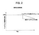
図2は、種々の燃料分割制御を示すグラフである。図2では、ヘッドエンドの燃料分割率と、燃焼器20及び/又は移行ゾーン43内の温度の測定値であるTfire値との関係を示している。コントローラ80は、更に、ヘッドエンド11及び/又は燃料噴射器60に向かう第1及び第2の燃料の流れ方向を制御するので、LLI燃料のステージングの制御も、図2の制御方式に従って、コントローラ80を用いて制御することができる。この場合、コントローラ80は、上記のように弁61及び弁73に接続されており、これにより、燃料噴射器60への第2の燃料の送出と、ヘッドエンド11への第1及び/又はLLI燃料の送出を制御する。Figure 2 is a viewto graphically various fuel split controls. FIG. 2 shows the relationship between the fuel split ratio at the head end and the Tfire value, which is a measured value of the temperature in the
図2において、かかる制御の第1方式は、固定ヘッドエンド分割を用いるものである。この場合、Tfire値が所定値に達すると、第1及び/又はLLI燃料の何パーセントか(<100%)をLLI燃料のステージング用に移行ゾーン43に送出する。従って、移行ゾーン43に送られる燃料のパーセント比はほぼ一定である。第2方式は、ヘッドエンド分割スケジュールを用いるものである。この場合、Tfire値が増加して予め設定した値を上回るので、LLI燃料のパーセント比は比例して、又は、何らかの他の適当な関数に従って増加する。第3方式は、LLI燃料のパーセント比を燃焼器20、圧縮機30、移行ゾーン43、及び/又は、タービン50の内部環境の幾つかの特徴のいずれかに基づく、1つ又は複数の関数にすることである。例えば、パーセント比を、測定された圧縮機排出温度及び圧力状態であるTcd又はPcd、燃焼器20、圧縮機30又は移行ゾーン43内からの湿度読み取り値、ガスタービン排気温度、及び/又は計算燃焼器出口温度であるT39の関数にすることができよう。In FIG. 2, the first method of such control uses fixed head end division. In this case, when the Tfire value reaches a predetermined value, some percentage (<100%) of the first and / or LLI fuel is delivered to the
上記の第3方式を、現在の修正ウォッベ指数(MWI)を示すように修正してもよい。MWIは、燃料のエネルギー密度であり、ある燃料ノズル面積において、MWIが低くなると、ヘッドエンド燃料のノズル全体での圧力比がそれだけ増加する。これは、動力学的の望ましくなく、LLI燃料ノズルを利用できなくなる可能性があることがわかっているので、LLI燃料のパーセント比をMWIの関数にしてもよい。このように、MWIが増加すると、移行ゾーン43に分岐するLLI燃料のパーセント比が大きくなる。熱電対/圧力計100又は何らかの他の適当な環境測定装置を燃焼器20、圧縮機30、移行ゾーン43及び/又はタービン50に設置して、上記の方式に従って、燃焼器20、圧縮機30、移行ゾーン43及びタービン50内の温度及び圧力を測定する。The third scheme above may be modified to indicate the current modified Wobbe index (MWI). MWI is the energy density of the fuel. When the MWI is lowered in a certain fuel nozzle area, the pressure ratio of the head end fuel across the nozzles is increased accordingly. Since this has been found to be kinetically undesirable and may cause the LLI fuel nozzle to become unavailable, the LLI fuel percentage ratio may be a function of MWI. Thus, as the MWI increases, the percentage ratio of LLI fuel that branches to the
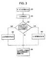
図3に、LLI機能を備えたタービンの制御方法を示す。本方法は、タービンを作動させること(ステップ300)、一定時間後に、又はTfireが所定値に達したら、LLIを始動させること(ステップ310)、更に、第1方式においては、LLIを同一レベルで動作させ続けること(ステップ350)を含む。本方法の第2方式の場合、ステップ350では、LLIを増加レベルで動作させ続ける。第3方式の場合、ステップ320において燃焼器20、圧縮機30及び/又は移行ゾーン43で測定された任意の特性が設定されたパラメータを上回っているか下回っているかを判定し、その決定結果に基づいて、LLIレベルを減少させたり(ステップ330)、増加又は維持したり(ステップ340)し、その後、ステップ350においてLLI動作を継続する。FIG. 3 shows a method for controlling a turbine having an LLI function. The method includes operating the turbine (step 300), starting a LLI after a certain time, or when Tfire reaches a predetermined value (step 310), and in the first scheme, the LLI is at the same level. Continuing to operate (step 350). In the case of the second method of the present method, in
再び図1を参照されたい。コントローラ80は更に、三方弁110の他に、一部の実施形態では、燃料噴射器60周囲のマニホルド上にある追加の弁、又は、上述のように弁61を制御する。すなわち、コントローラ80を用いて、圧縮機30から燃焼器20及び移行ゾーン43に、又は、各燃料噴射器60に送られた吸気の気流分割を制御することができる。このように、コントローラ80を用いて、燃料分割及び気流分割を同時に制御することができる。従って、コントローラ80により、燃焼システムの最適空燃比に基づいて、燃焼システムの作動経路を形成することができる。本発明の実施形態として、三方弁110は、更に、あらゆる空気冷却システムにも適用可能であり、ひいては、ターンダウン活動及び/又はエネルギー省(DoE)プログラムの一助となるであろう。Please refer to FIG. 1 again. In addition to the three-
上述のように、三方弁110の制御により、燃焼システムの空燃比を最適化することができる。燃焼器20及び移行ゾーン43の仕様、又は、現在の動作状態に基づいて、この空燃比を予め設定しておくことができる。そうすると、燃焼器20、圧縮機30、移行ゾーン43及びタービン50内に設置された熱電対/圧力計100からの温度及び/又は圧力読み取り値に基づいて、コントローラ80は、燃焼器20又は移行ゾーン43のいずれか一方の空燃比を増加させる。As described above, the air-fuel ratio of the combustion system can be optimized by controlling the three-
希薄遅延噴射(LLI)により、一般的にはLLIに対応していない燃焼器では使えない、製油所ガスなどの代替ガスをはじめとする様々なガス流を移行ゾーン43に噴射できるようになる。製油所ガスなどの反応性が非常に高いガスは、通常、予混合器内の保炎性の観点から、予混合燃焼器で取り扱うことができない。しかし、特に燃料噴射器60に耐火性がある場合、製油所ガスを、天然ガスと混合しても(しなくてもよいが)、そのような問題を伴わないで移行ゾーン43内へ直接噴射できることもある。ここで、製油所ガスを天然ガスと混合する場合、天然ガスの使用量は、例えば上述のように、Tcd、Pcd及びT39の関数である。また、製油所ガスを移行ゾーン43内へ噴射する場合、保炎事故を防止するために、火炎を検知可能な予混合器をヘッドエンド11に用いることができる。Lean delayed injection (LLI) allows various gas flows, including alternative gases such as refinery gas, that cannot be used with combustors that do not generally support LLI to be injected into the
図1の例では、代替ガスを、供給源90から、コントローラ80によって制御された製油所ガス弁91を介して、燃料回路70のブランチ71又は72へ噴射する。このように、代替ガスを移行ゾーン43内へ噴射すると決定した場合、コントローラ80は、製油所ガス弁91を開き、燃料回路70を介して代替ガスを燃料噴射器60に送る。In the example of FIG. 1, alternative gas is injected from the supply source 90 into the
別の実施形態として、代替ガスを天然ガスと混合して、使用時にヘッドエンド11の耐性に合った組成の第1の燃料を生成することができる。第2の燃料の生成には、そのような混合を行っても、行わなくても、代替ガスを準備することができる。As another embodiment, the alternative gas is mixed with natural gas, it is possible to generate afirst fuel composition that matches the resistance of the
加えて、代替ガスは、上述のように、燃料回路70が供給源90から受け取った製油所ガス、及びメタンより反応性が高い成分を含有するガスであってもよい。代替ガスは、例えば、約0.5体積%を上回る水素と、約5体積%を上回るエタンと、約10体積%を上回るプロパンと、約5体積%を上回るブタン又はブタンより上位の炭化水素を含有するガスであってもよい。 In addition, the alternative gas may be a refinery gas received by the
燃料流に応じて、燃料回路70に複数のブランチ71及び72を組み込むこともできる。複数のブランチ71及び72によって燃料流の面積を増やすことで、又は、燃焼モード(すなわち、拡散及び予混合)を適用して燃料を導入することで、組成が大きく異なる燃料にも対応できる。ブランチ71及び72により、燃料ウォッベ指数や、燃料組成の調節、流れの変更も可能である。燃料回路70のブランチ71及び72は、燃料回路70のブランチとしても、移行ゾーン43の追加の燃料ノズルとしても、この組合せとしても、又は、その他の適当な態様で使用可能である。Depending on the fuel flow, a plurality of
ブランチ71及び72は、更に、長さ方向に沿って配置された触媒部分酸化反応器(CPCR)120を含んでもよい。CPCR120により、第1又は第2の燃料内のメタンを水素に変換し、且つ/又は、窒素酸化物を生じることなくメタンを部分的に酸化することができる。その結果、LLIに使用する反応済み燃料が既に部分的に酸化された状態で、CPCR120を使用しない場合よりも、更に遅らせて燃料を移行ゾーン43内へ噴射することができる。The
以上、一部の実施形態についてのみ、本発明を説明してきたが、明らかなように、本発明の実施形態は本明細書に記載のものに限られない。これらの実施形態にいかなる修正、改変、代替、等価の措置を加えても、本発明の実施形態として認められる。また、本発明の実施形態の態様うち、開示の内容はその一部にすぎない。本発明は、添付の特許請求の範囲に基づいてのみ解釈されるべきであって、本明細書の説明に限定されるものではない。 As mentioned above, although this invention was demonstrated only about one part embodiment, embodiment of this invention is not restricted to what is described in this specification clearly. Any modification, alteration, substitution, or equivalent measure added to these embodiments is recognized as an embodiment of the present invention. Moreover, the content of an indication is only one part among the aspects of embodiment of this invention. The present invention should be construed based solely on the scope of the appended claims, and is not limited to the description herein.
10 ガスタービンエンジン
11 ヘッドエンド
12 複数の予混合ノズル
13 一般的な燃焼器
14 (DLN)1+燃焼器
15 (DLN)2+燃焼器
16 DLN2.6/2.6+燃焼器
20 燃焼器
21 第1の内部空間
40 スリーブ
41 第2の内部空間
42 希釈孔
43 移行ゾーン
50 タービン
60 燃料噴射器
61 弁
70 燃料回路
71、72 ブランチ
80 コントローラ
90 供給源
91 製油所ガス弁
100 熱電対/圧力計
110 三方弁
120 触媒部分酸化反応器
125 チューブ・イン・チューブ噴射器
130 チューブ
140 スリーブ衝突面
145 スリーブ
150 接合部分
155 スワール噴射器
160 マニホルド
165 パージ
170 スワーラ
175 高濃度触媒噴射器
180 高濃度触媒要素
185 複数のチューブ/シャワーヘッド噴射器
190 複数のチューブ
300 タービンを動作させる
310 LLIを始動する
320 判定を行う
330 LLIレベルを減少させる
340 LLIを増加させる
350 LLIの動作を継続10
Claims (8)
Translated fromJapanese燃料回路(70)から供給される第1の燃料を燃焼させる第1の内部空間(21)を有する燃焼器(20)と、
回転タービンブレードを有するタービン(50)であって、少なくとも第1の燃料の燃焼生成物を受け取ってタービンブレードに回転力を与えるタービン(50)と、
前記燃料回路(70)から供給される第2の燃料と第1の燃料の燃焼生成物とを燃焼させることのできる第2の内部空間(41)を含む移行ゾーン(43)であって、前記燃焼器(20)と前記タービン(50)とを互いに流体接続させる移行ゾーン(43)と、
前記移行ゾーン(43)によって構造的に支持され、前記燃料回路(70)に接続された複数の燃料噴射器(60)であって、第2の燃料を第2の内部空間(41)に軸方向単段、軸方向多段、軸方向単段周方向段及び軸方向多段周方向段のいずれかで供給するように構成された複数の燃料噴射器(60)と、
前記燃焼器(20)及び前記移行ゾーン(43)に流体接続された圧縮機(30)であって、燃焼用の空気を第1及び第2の内部空間(21、41)に供給する圧縮機(30)と、
前記燃料回路(70)に接続された制御システムであって、第1及び第2の内部空間(21、41)への空気の相対量、及び前記燃料回路(70)から第1及び第2の内部空間(21、41)に供給される第1及び第2の燃料の相対量を制御する制御システムと、
前記制御システムによって制御される製油所ガス弁(91)であって、弁を開いたときに製油所ガスを前記燃料回路(70)を通して前記燃料噴射器(60)に送るための製油所ガス弁(91)と
を備える、ガスタービンエンジン(10)。A gas turbine engine (10) comprising:
First combustor having an internalspace (21) to burn thefirst fuelthat will be supplied from the fuel circuit (70) and (20),
A turbine having a rotating turbine blade (50), a turbine (50) to impart rotational force to the turbine bladeI receive at least the combustion productsof thefirst fuel,
Asecond fuel and the secondtransitionzone comprising an internalspace (41) to the combustion productsof thefirst fuelcan be burnedthat will be supplied from the fuel circuit (70) (43), wherein a combustor (20)and said turbine (50)and transitionzone Ru was in fluid communication with each other (43),
The structurally supported bythe transitionzone (43), wherein the fuel circuit connected multiple fuel injectors (70) A (60),the axis of thesecond fuel to thesecond interiorspace (41) A plurality of fuel injectors (60) configured to supply inany one of directionalsingle stage ,axialmultistage ,axial singlestage circumferential stage and axialmultistage circumferential stage ;
Said combustor (20) and said a transitionzone (43) in fluid connection to acompressor (30),a compressor for supplyingair for combustionto thefirst andsecond innerspaces (21, 41) (30),
A control system connected to the fuel circuit (70), the relative amounts of air intothe first andsecond innerspaces (21, 41), andthe fuel circuit (70) fromthefirst and second a control system for controlling the relative amounts of thefirst andsecond fuel thatwill be supplied to the internalspace (21,41),
A refinery gas valve (91) controlled by the control system for sending refinery gas through the fuel circuit (70) to the fuel injector (60) when the valve is opened. (91) andRu with a <br/>, gas turbine engine (10).
圧縮機(30)の出口近傍に設置され、前記圧縮機(30)と前記燃焼器(20)と前記移行ゾーン(43)との間に介在する三方弁(110)と、
前記三方弁(110)に接続されたコントローラ(80)であって、前記三方弁(110)の開閉動作によって、第1及び第2の内部空間(21、41)に供給する空気の相対量の増加及び減少の少なくともいずれかを行うコントローラ(80)とを備える、請求項1に記載のガスタービンエンジン(10)。The control system is
Placed near the outlet of the compressor (30), thecompressor (30)and the combustor (20)andthree-way valve interposedbetween said transitionzone (43) and (110),
Wherein athree-way valve (110) connected to a controller (80), the opening and closing operationof thethree-way valve (110), the relative amounts of air supplied to thefirst andsecond innerspaces (21, 41) The gas turbine engine (10) according to claim 1, comprising a controller (80) for increasing and / or decreasing.
第1の燃料を燃焼器(20)の第1の内部空間(21)に供給する段階と、
第1の燃料を前記燃焼器(20)の第1の内部空間(21)で燃焼させる段階と、
第2の燃料を前記移行ゾーン(43)の第2の内部空間(41)に軸方向単段、軸方向多段、軸方向単段周方向段及び軸方向多段周方向段のいずれかで供給する段階と、
第2の燃料と第1の内部空間(21)から受け取った燃焼生成物の流れとを前記移行ゾーン(43)の第2の内部空間(41)で燃焼させる段階と、
空気と第1及び第2の内部空間(21、41)に供給される第1及び第2の燃料との相対量を制御する段階と、
製油所ガスを前記燃料回路(70)を通して前記燃料噴射器(60)に送るための製油所ガス弁(91)を制御する段階と
を含む方法。Turbine (50)and the combustor (20) via adisposed a transitionzone (43)betweentheturbine (50) and the combustor (20) and isoptionally fluidly connected, aircompressor (30 ) From the gas turbine engine (10) supplied to the combustor (20) and the transitionzone (43),
And supplying afirst fuel toa first interiorspace of the combustor (20) (21),
The method comprising combusting in thefirst fuelfirst internalspace of the combustor (20) (21),
Suppliedin one ofthe secondaxialsingle stage in an internalspace (41),multipleaxialstages, a singleaxialstage circumferential stage andmultipleaxialstages circumferential stages of the transitionzone of the secondfuel (43)Stages ,
A method for combusting a flowof thesecond fuel andthefirst combustion products, received from the internalspace (21) in the interiorspace (41)secondof the transitionzone (43),
And controlling the relative amounts of air andthe first andsecond fuelthat will be supplied to thefirst andsecond innerspaces (21,41),
Controlling a refinery gas valve (91) for sending refinery gas through the fuel circuit (70) to the fuel injector (60) .
Applications Claiming Priority (2)
| Application Number | Priority Date | Filing Date | Title |
|---|---|---|---|
| US12/349,933US8112216B2 (en) | 2009-01-07 | 2009-01-07 | Late lean injection with adjustable air splits |
| US12/349,933 | 2009-01-07 |
Publications (3)
| Publication Number | Publication Date |
|---|---|
| JP2010159956A JP2010159956A (en) | 2010-07-22 |
| JP2010159956A5 JP2010159956A5 (en) | 2014-05-15 |
| JP5683102B2true JP5683102B2 (en) | 2015-03-11 |
Family
ID=42041849
Family Applications (1)
| Application Number | Title | Priority Date | Filing Date |
|---|---|---|---|
| JP2009296996AExpired - Fee RelatedJP5683102B2 (en) | 2009-01-07 | 2009-12-28 | Lean delayed injection with adjustment of airflow division |
Country Status (4)
| Country | Link |
|---|---|
| US (3) | US8112216B2 (en) |
| EP (1) | EP2206961A3 (en) |
| JP (1) | JP5683102B2 (en) |
| CN (1) | CN101776018B (en) |
Families Citing this family (116)
| Publication number | Priority date | Publication date | Assignee | Title |
|---|---|---|---|---|
| US8112216B2 (en) | 2009-01-07 | 2012-02-07 | General Electric Company | Late lean injection with adjustable air splits |
| TWI564475B (en)* | 2010-07-02 | 2017-01-01 | 艾克頌美孚上游研究公司 | Low emission triple-cycle power generation systems and methods |
| MX354587B (en)* | 2010-07-02 | 2018-03-12 | Exxonmobil Upstream Res Company Star | Stoichiometric combustion of enriched air with exhaust gas recirculation. |
| US20120102914A1 (en)* | 2010-11-03 | 2012-05-03 | General Electric Company | Systems, methods, and apparatus for compensating fuel composition variations in a gas turbine |
| US8601820B2 (en) | 2011-06-06 | 2013-12-10 | General Electric Company | Integrated late lean injection on a combustion liner and late lean injection sleeve assembly |
| WO2013002669A1 (en) | 2011-06-30 | 2013-01-03 | General Electric Company | Combustor and method of supplying fuel to the combustor |
| EP2726786B1 (en) | 2011-06-30 | 2018-04-04 | General Electric Company | Combustor and method of supplying fuel to the combustor |
| US9032785B1 (en) | 2011-07-01 | 2015-05-19 | The United States Of America As Represented By The Administrator National Aeronautics And Space Administration | Method for making measurements of the post-combustion residence time in a gas turbine engine |
| US8407892B2 (en) | 2011-08-05 | 2013-04-02 | General Electric Company | Methods relating to integrating late lean injection into combustion turbine engines |
| US9010120B2 (en) | 2011-08-05 | 2015-04-21 | General Electric Company | Assemblies and apparatus related to integrating late lean injection into combustion turbine engines |
| US8919137B2 (en)* | 2011-08-05 | 2014-12-30 | General Electric Company | Assemblies and apparatus related to integrating late lean injection into combustion turbine engines |
| US9303872B2 (en)* | 2011-09-15 | 2016-04-05 | General Electric Company | Fuel injector |
| WO2013043076A1 (en) | 2011-09-22 | 2013-03-28 | General Electric Company | Combustor and method for supplying fuel to a combustor |
| US8904796B2 (en)* | 2011-10-19 | 2014-12-09 | General Electric Company | Flashback resistant tubes for late lean injector and method for forming the tubes |
| US20130111918A1 (en)* | 2011-11-07 | 2013-05-09 | General Electric Company | Combustor assembly for a gas turbomachine |
| CN103917826B (en)* | 2011-11-17 | 2016-08-24 | 通用电气公司 | Turbomachine combustor assembly and the method for operation turbine |
| US9140455B2 (en) | 2012-01-04 | 2015-09-22 | General Electric Company | Flowsleeve of a turbomachine component |
| US9170024B2 (en) | 2012-01-06 | 2015-10-27 | General Electric Company | System and method for supplying a working fluid to a combustor |
| US9243507B2 (en) | 2012-01-09 | 2016-01-26 | General Electric Company | Late lean injection system transition piece |
| US9188337B2 (en) | 2012-01-13 | 2015-11-17 | General Electric Company | System and method for supplying a working fluid to a combustor via a non-uniform distribution manifold |
| US9097424B2 (en) | 2012-03-12 | 2015-08-04 | General Electric Company | System for supplying a fuel and working fluid mixture to a combustor |
| US9151500B2 (en) | 2012-03-15 | 2015-10-06 | General Electric Company | System for supplying a fuel and a working fluid through a liner to a combustion chamber |
| US9052115B2 (en) | 2012-04-25 | 2015-06-09 | General Electric Company | System and method for supplying a working fluid to a combustor |
| US9284888B2 (en) | 2012-04-25 | 2016-03-15 | General Electric Company | System for supplying fuel to late-lean fuel injectors of a combustor |
| US8677753B2 (en) | 2012-05-08 | 2014-03-25 | General Electric Company | System for supplying a working fluid to a combustor |
| US8887506B2 (en) | 2012-05-11 | 2014-11-18 | General Electric Company | Fuel injector with mixing circuit |
| US9733141B1 (en)* | 2012-06-27 | 2017-08-15 | The United States Of America As Represented By The Administrator Of National Aeronautics And Space Administration | Method for making measurements of the post-combustion residence time in a gas turbine engine |
| US8479518B1 (en) | 2012-07-11 | 2013-07-09 | General Electric Company | System for supplying a working fluid to a combustor |
| US8683805B2 (en)* | 2012-08-06 | 2014-04-01 | General Electric Company | Injector seal for a gas turbomachine |
| EP2888531B1 (en)* | 2012-08-24 | 2020-06-17 | Ansaldo Energia Switzerland AG | Sequential combustion with dilution gas mixer |
| US9423131B2 (en) | 2012-10-10 | 2016-08-23 | General Electric Company | Air management arrangement for a late lean injection combustor system and method of routing an airflow |
| US9803498B2 (en)* | 2012-10-17 | 2017-10-31 | United Technologies Corporation | One-piece fuel nozzle for a thrust engine |
| US9310078B2 (en) | 2012-10-31 | 2016-04-12 | General Electric Company | Fuel injection assemblies in combustion turbine engines |
| US9291098B2 (en)* | 2012-11-14 | 2016-03-22 | General Electric Company | Turbomachine and staged combustion system of a turbomachine |
| US20140216044A1 (en)* | 2012-12-17 | 2014-08-07 | United Technologoes Corporation | Gas turbine engine combustor heat shield with increased film cooling effectiveness |
| US10088165B2 (en) | 2015-04-07 | 2018-10-02 | General Electric Company | System and method for tuning resonators |
| US9279369B2 (en)* | 2013-03-13 | 2016-03-08 | General Electric Company | Turbomachine with transition piece having dilution holes and fuel injection system coupled to transition piece |
| US9482434B2 (en) | 2013-03-15 | 2016-11-01 | General Electric Company | Methods relating to downstream fuel and air injection in gas turbines |
| US9377202B2 (en) | 2013-03-15 | 2016-06-28 | General Electric Company | System and method for fuel blending and control in gas turbines |
| US9528439B2 (en)* | 2013-03-15 | 2016-12-27 | General Electric Company | Systems and apparatus relating to downstream fuel and air injection in gas turbines |
| US9714768B2 (en)* | 2013-03-15 | 2017-07-25 | General Electric Company | Systems and apparatus relating to downstream fuel and air injection in gas turbines |
| US9435541B2 (en) | 2013-03-15 | 2016-09-06 | General Electric Company | Systems and apparatus relating to downstream fuel and air injection in gas turbines |
| US9400114B2 (en) | 2013-03-18 | 2016-07-26 | General Electric Company | Combustor support assembly for mounting a combustion module of a gas turbine |
| US9322556B2 (en) | 2013-03-18 | 2016-04-26 | General Electric Company | Flow sleeve assembly for a combustion module of a gas turbine combustor |
| US9360217B2 (en) | 2013-03-18 | 2016-06-07 | General Electric Company | Flow sleeve for a combustion module of a gas turbine |
| US9316155B2 (en) | 2013-03-18 | 2016-04-19 | General Electric Company | System for providing fuel to a combustor |
| US9383104B2 (en) | 2013-03-18 | 2016-07-05 | General Electric Company | Continuous combustion liner for a combustor of a gas turbine |
| US10436445B2 (en) | 2013-03-18 | 2019-10-08 | General Electric Company | Assembly for controlling clearance between a liner and stationary nozzle within a gas turbine |
| US9376961B2 (en)* | 2013-03-18 | 2016-06-28 | General Electric Company | System for controlling a flow rate of a compressed working fluid to a combustor fuel injector |
| US9291350B2 (en) | 2013-03-18 | 2016-03-22 | General Electric Company | System for providing a working fluid to a combustor |
| US9631812B2 (en) | 2013-03-18 | 2017-04-25 | General Electric Company | Support frame and method for assembly of a combustion module of a gas turbine |
| US9316396B2 (en) | 2013-03-18 | 2016-04-19 | General Electric Company | Hot gas path duct for a combustor of a gas turbine |
| US9382850B2 (en) | 2013-03-21 | 2016-07-05 | General Electric Company | System and method for controlled fuel blending in gas turbines |
| EP2789915A1 (en)* | 2013-04-10 | 2014-10-15 | Alstom Technology Ltd | Method for operating a combustion chamber and combustion chamber |
| EP3008391B1 (en) | 2013-06-11 | 2020-05-06 | United Technologies Corporation | Combustor with axial staging for a gas turbine engine |
| US20150052905A1 (en)* | 2013-08-20 | 2015-02-26 | General Electric Company | Pulse Width Modulation for Control of Late Lean Liquid Injection Velocity |
| US20150059348A1 (en)* | 2013-08-28 | 2015-03-05 | General Electric Company | System and method for controlling fuel distributions in a combustor in a gas turbine engine |
| US20150075170A1 (en)* | 2013-09-17 | 2015-03-19 | General Electric Company | Method and system for augmenting the detection reliability of secondary flame detectors in a gas turbine |
| GB201317175D0 (en) | 2013-09-27 | 2013-11-06 | Rolls Royce Plc | An apparatus and a method of controlling the supply of fuel to a combustion chamber |
| US20150107255A1 (en)* | 2013-10-18 | 2015-04-23 | General Electric Company | Turbomachine combustor having an externally fueled late lean injection (lli) system |
| US20150159877A1 (en)* | 2013-12-06 | 2015-06-11 | General Electric Company | Late lean injection manifold mixing system |
| US9689574B2 (en) | 2014-02-03 | 2017-06-27 | General Electric Company | System and method for reducing modal coupling of combustion dynamics |
| US9964045B2 (en) | 2014-02-03 | 2018-05-08 | General Electric Company | Methods and systems for detecting lean blowout in gas turbine systems |
| US9644845B2 (en) | 2014-02-03 | 2017-05-09 | General Electric Company | System and method for reducing modal coupling of combustion dynamics |
| US9709279B2 (en) | 2014-02-27 | 2017-07-18 | General Electric Company | System and method for control of combustion dynamics in combustion system |
| US9709278B2 (en)* | 2014-03-12 | 2017-07-18 | General Electric Company | System and method for control of combustion dynamics in combustion system |
| JP6257035B2 (en)* | 2014-03-25 | 2018-01-10 | 三菱日立パワーシステムズ株式会社 | Combustion control device, combustion control method and program for gas turbine |
| US10221777B2 (en)* | 2014-03-25 | 2019-03-05 | Mitsubishi Hitachi Power Systems, Ltd. | Gas turbine combustion control device and combustion control method and program therefor |
| US9644846B2 (en) | 2014-04-08 | 2017-05-09 | General Electric Company | Systems and methods for control of combustion dynamics and modal coupling in gas turbine engine |
| US9845956B2 (en) | 2014-04-09 | 2017-12-19 | General Electric Company | System and method for control of combustion dynamics in combustion system |
| US9803555B2 (en)* | 2014-04-23 | 2017-10-31 | General Electric Company | Fuel delivery system with moveably attached fuel tube |
| US9845732B2 (en) | 2014-05-28 | 2017-12-19 | General Electric Company | Systems and methods for variation of injectors for coherence reduction in combustion system |
| US9551283B2 (en) | 2014-06-26 | 2017-01-24 | General Electric Company | Systems and methods for a fuel pressure oscillation device for reduction of coherence |
| US9909508B2 (en)* | 2014-06-26 | 2018-03-06 | General Electric Company | Automatic combustion system characterization |
| US10094569B2 (en)* | 2014-12-11 | 2018-10-09 | General Electric Company | Injecting apparatus with reheat combustor and turbomachine |
| US10094571B2 (en)* | 2014-12-11 | 2018-10-09 | General Electric Company | Injector apparatus with reheat combustor and turbomachine |
| US10107498B2 (en) | 2014-12-11 | 2018-10-23 | General Electric Company | Injection systems for fuel and gas |
| US10094570B2 (en) | 2014-12-11 | 2018-10-09 | General Electric Company | Injector apparatus and reheat combustor |
| EP3037726B1 (en)* | 2014-12-22 | 2018-09-26 | Ansaldo Energia Switzerland AG | Separate feedings of cooling and dilution air |
| US10060629B2 (en)* | 2015-02-20 | 2018-08-28 | United Technologies Corporation | Angled radial fuel/air delivery system for combustor |
| US10480792B2 (en)* | 2015-03-06 | 2019-11-19 | General Electric Company | Fuel staging in a gas turbine engine |
| US10113747B2 (en) | 2015-04-15 | 2018-10-30 | General Electric Company | Systems and methods for control of combustion dynamics in combustion system |
| KR102096434B1 (en) | 2015-07-07 | 2020-04-02 | 한화에어로스페이스 주식회사 | Combustor |
| US9938903B2 (en) | 2015-12-22 | 2018-04-10 | General Electric Company | Staged fuel and air injection in combustion systems of gas turbines |
| US9976487B2 (en) | 2015-12-22 | 2018-05-22 | General Electric Company | Staged fuel and air injection in combustion systems of gas turbines |
| US9945294B2 (en) | 2015-12-22 | 2018-04-17 | General Electric Company | Staged fuel and air injection in combustion systems of gas turbines |
| US10337411B2 (en) | 2015-12-30 | 2019-07-02 | General Electric Company | Auto thermal valve (ATV) for dual mode passive cooling flow modulation |
| US20170191373A1 (en) | 2015-12-30 | 2017-07-06 | General Electric Company | Passive flow modulation of cooling flow into a cavity |
| JP6651389B2 (en)* | 2016-03-08 | 2020-02-19 | 三菱日立パワーシステムズ株式会社 | Fuel control device, combustor, gas turbine, fuel control method and program |
| US20170260866A1 (en)* | 2016-03-10 | 2017-09-14 | Siemens Energy, Inc. | Ducting arrangement in a combustion system of a gas turbine engine |
| US20170268776A1 (en)* | 2016-03-15 | 2017-09-21 | General Electric Company | Gas turbine flow sleeve mounting |
| EP3228939B1 (en) | 2016-04-08 | 2020-08-05 | Ansaldo Energia Switzerland AG | Method for combusting a fuel, and combustion appliance |
| US10222066B2 (en) | 2016-05-26 | 2019-03-05 | Siemens Energy, Inc. | Ducting arrangement with injector assemblies arranged in an expanding cross-sectional area of a downstream combustion stage in a gas turbine engine |
| US10215038B2 (en) | 2016-05-26 | 2019-02-26 | Siemens Energy, Inc. | Method and computer-readable model for additively manufacturing ducting arrangement for a gas turbine engine |
| DE102016112887A1 (en)* | 2016-07-13 | 2018-01-18 | Truma Gerätetechnik GmbH & Co. KG | Heating device and method for operating a heating device |
| US10337739B2 (en) | 2016-08-16 | 2019-07-02 | General Electric Company | Combustion bypass passive valve system for a gas turbine |
| US10738704B2 (en)* | 2016-10-03 | 2020-08-11 | Raytheon Technologies Corporation | Pilot/main fuel shifting in an axial staged combustor for a gas turbine engine |
| US10508811B2 (en)* | 2016-10-03 | 2019-12-17 | United Technologies Corporation | Circumferential fuel shifting and biasing in an axial staged combustor for a gas turbine engine |
| US10739003B2 (en) | 2016-10-03 | 2020-08-11 | United Technologies Corporation | Radial fuel shifting and biasing in an axial staged combustor for a gas turbine engine |
| JP7214332B2 (en)* | 2017-01-18 | 2023-01-30 | ゼネラル・エレクトリック・カンパニイ | Staged fuel and air injection in gas turbine combustion systems |
| US10712007B2 (en) | 2017-01-27 | 2020-07-14 | General Electric Company | Pneumatically-actuated fuel nozzle air flow modulator |
| US10738712B2 (en) | 2017-01-27 | 2020-08-11 | General Electric Company | Pneumatically-actuated bypass valve |
| JP6769370B2 (en)* | 2017-03-27 | 2020-10-14 | 株式会社Ihi | Combustion equipment and gas turbine |
| US11137144B2 (en) | 2017-12-11 | 2021-10-05 | General Electric Company | Axial fuel staging system for gas turbine combustors |
| US11187415B2 (en) | 2017-12-11 | 2021-11-30 | General Electric Company | Fuel injection assemblies for axial fuel staging in gas turbine combustors |
| US10816203B2 (en) | 2017-12-11 | 2020-10-27 | General Electric Company | Thimble assemblies for introducing a cross-flow into a secondary combustion zone |
| CN111486477B (en)* | 2020-04-07 | 2021-04-20 | 南京航空航天大学 | Blending hole adjustment system and method for adjusting combustion chamber outlet temperature distribution |
| US11371709B2 (en) | 2020-06-30 | 2022-06-28 | General Electric Company | Combustor air flow path |
| US11566790B1 (en)* | 2021-10-28 | 2023-01-31 | General Electric Company | Methods of operating a turbomachine combustor on hydrogen |
| US12379108B2 (en) | 2023-01-06 | 2025-08-05 | Ge Vernova Infrastructure Technology Llc | Method of operating gas turbine combustor with multiple fuel stages |
| US20240230090A1 (en)* | 2023-01-06 | 2024-07-11 | Ge Infrastructure Technology Llc | Combustor head end section with air supply system for bundled tube fuel nozzle contained therein |
| US20250067436A1 (en)* | 2023-08-25 | 2025-02-27 | Ge Infrastructure Technology Llc | Ammonia combustor |
| US12429222B2 (en) | 2023-08-25 | 2025-09-30 | Ge Vernova Infrastructure Technology Llc | Flex fuel combustor |
| US12281794B1 (en) | 2023-12-29 | 2025-04-22 | Ge Infrastructure Technology Llc | Combustor body and axial fuel stage immersed injectors additively manufactured with different materials |
| US12203655B1 (en) | 2023-12-29 | 2025-01-21 | Ge Infrastructure Technology Llc | Additively manufactured combustor with adaptive cooling passage |
| US12092061B1 (en) | 2023-12-29 | 2024-09-17 | Ge Infrastructure Technology Llc | Axial fuel stage immersed injectors with internal cooling |
Family Cites Families (46)
| Publication number | Priority date | Publication date | Assignee | Title |
|---|---|---|---|---|
| US3045425A (en)* | 1954-03-03 | 1962-07-24 | Snecma | Exhaust reheat equipment for gasturbine engines |
| DE2232025A1 (en)* | 1972-06-30 | 1974-01-17 | Motoren Turbinen Union | GAS TURBINE SYSTEM, IN PARTICULAR ENGINE WITH COUNTER-ROOM COMBUSTION |
| JPS62174539A (en)* | 1985-09-30 | 1987-07-31 | Toshiba Corp | Gas turbine controller |
| US4735052A (en)* | 1985-09-30 | 1988-04-05 | Kabushiki Kaisha Toshiba | Gas turbine apparatus |
| GB2219045B (en)* | 1988-05-27 | 1992-06-03 | Rolls Royce Plc | Gas turbine engine fuel system |
| US5163284A (en) | 1991-02-07 | 1992-11-17 | Sundstrand Corporation | Dual zone combustor fuel injection |
| JP3154426B2 (en)* | 1992-01-28 | 2001-04-09 | 三菱瓦斯化学株式会社 | Pretreatment method of fuel gas for gas turbine device |
| GB2284884B (en)* | 1993-12-16 | 1997-12-10 | Rolls Royce Plc | A gas turbine engine combustion chamber |
| JP2950720B2 (en)* | 1994-02-24 | 1999-09-20 | 株式会社東芝 | Gas turbine combustion device and combustion control method therefor |
| DE4416650A1 (en)* | 1994-05-11 | 1995-11-16 | Abb Management Ag | Combustion process for atmospheric combustion plants |
| CH688899A5 (en)* | 1994-05-26 | 1998-05-15 | Asea Brown Boveri | A method for controlling a gas turbine group. |
| US5943866A (en)* | 1994-10-03 | 1999-08-31 | General Electric Company | Dynamically uncoupled low NOx combustor having multiple premixers with axial staging |
| US5836164A (en)* | 1995-01-30 | 1998-11-17 | Hitachi, Ltd. | Gas turbine combustor |
| US5826429A (en) | 1995-12-22 | 1998-10-27 | General Electric Co. | Catalytic combustor with lean direct injection of gas fuel for low emissions combustion and methods of operation |
| US5974781A (en)* | 1995-12-26 | 1999-11-02 | General Electric Company | Hybrid can-annular combustor for axial staging in low NOx combustors |
| US6201029B1 (en)* | 1996-02-13 | 2001-03-13 | Marathon Oil Company | Staged combustion of a low heating value fuel gas for driving a gas turbine |
| US6047550A (en)* | 1996-05-02 | 2000-04-11 | General Electric Co. | Premixing dry low NOx emissions combustor with lean direct injection of gas fuel |
| US5901547A (en)* | 1996-06-03 | 1999-05-11 | Air Products And Chemicals, Inc. | Operation method for integrated gasification combined cycle power generation system |
| US6105359A (en)* | 1997-03-31 | 2000-08-22 | Wilson; Michael A. | Efficiency enhanced turbine engine |
| DE19741197C1 (en)* | 1997-09-18 | 1999-01-28 | Siemens Ag | Adaptor fitting for stationary gas turbine plant |
| FR2774152B1 (en)* | 1998-01-28 | 2000-03-24 | Inst Francais Du Petrole | COMBUSTION CHAMBER OF GAS TURBINE OPERATING ON LIQUID FUEL |
| FR2795716B1 (en)* | 1999-07-02 | 2001-08-03 | Air Liquide | PROCESS FOR CALCINATION OF A MATERIAL BASED ON ORE |
| US6868676B1 (en)* | 2002-12-20 | 2005-03-22 | General Electric Company | Turbine containing system and an injector therefor |
| US7284378B2 (en)* | 2004-06-04 | 2007-10-23 | General Electric Company | Methods and apparatus for low emission gas turbine energy generation |
| US7010921B2 (en)* | 2004-06-01 | 2006-03-14 | General Electric Company | Method and apparatus for cooling combustor liner and transition piece of a gas turbine |
| US7395670B1 (en)* | 2005-02-18 | 2008-07-08 | Praxair Technology, Inc. | Gas turbine fuel preparation and introduction method |
| JP2007107401A (en)* | 2005-10-11 | 2007-04-26 | Chugoku Electric Power Co Inc:The | Gas supply device for thermal power generation installation |
| JP4831820B2 (en)* | 2006-05-22 | 2011-12-07 | 三菱重工業株式会社 | Gas turbine output learning circuit and gas turbine combustion control apparatus having the same |
| US20070277530A1 (en)* | 2006-05-31 | 2007-12-06 | Constantin Alexandru Dinu | Inlet flow conditioner for gas turbine engine fuel nozzle |
| US8141370B2 (en)* | 2006-08-08 | 2012-03-27 | General Electric Company | Methods and apparatus for radially compliant component mounting |
| US7810333B2 (en)* | 2006-10-02 | 2010-10-12 | General Electric Company | Method and apparatus for operating a turbine engine |
| US7690188B2 (en)* | 2007-03-02 | 2010-04-06 | United Technologies Corporation | Combination engines for aircraft |
| JP4719704B2 (en)* | 2007-03-09 | 2011-07-06 | 株式会社日立製作所 | Gas turbine combustor |
| US7886545B2 (en)* | 2007-04-27 | 2011-02-15 | General Electric Company | Methods and systems to facilitate reducing NOx emissions in combustion systems |
| US7886539B2 (en)* | 2007-09-14 | 2011-02-15 | Siemens Energy, Inc. | Multi-stage axial combustion system |
| US8387398B2 (en)* | 2007-09-14 | 2013-03-05 | Siemens Energy, Inc. | Apparatus and method for controlling the secondary injection of fuel |
| US8397512B2 (en)* | 2008-08-25 | 2013-03-19 | General Electric Company | Flow device for turbine engine and method of assembling same |
| US8113000B2 (en)* | 2008-09-15 | 2012-02-14 | Siemens Energy, Inc. | Flashback resistant pre-mixer assembly |
| US8272218B2 (en) | 2008-09-24 | 2012-09-25 | Siemens Energy, Inc. | Spiral cooled fuel nozzle |
| US9822649B2 (en)* | 2008-11-12 | 2017-11-21 | General Electric Company | Integrated combustor and stage 1 nozzle in a gas turbine and method |
| US8701383B2 (en) | 2009-01-07 | 2014-04-22 | General Electric Company | Late lean injection system configuration |
| US8701418B2 (en) | 2009-01-07 | 2014-04-22 | General Electric Company | Late lean injection for fuel flexibility |
| US8683808B2 (en) | 2009-01-07 | 2014-04-01 | General Electric Company | Late lean injection control strategy |
| US8701382B2 (en) | 2009-01-07 | 2014-04-22 | General Electric Company | Late lean injection with expanded fuel flexibility |
| US8707707B2 (en) | 2009-01-07 | 2014-04-29 | General Electric Company | Late lean injection fuel staging configurations |
| US8112216B2 (en) | 2009-01-07 | 2012-02-07 | General Electric Company | Late lean injection with adjustable air splits |
- 2009
- 2009-01-07USUS12/349,933patent/US8112216B2/ennot_activeExpired - Fee Related
- 2009-12-18EPEP09180046Apatent/EP2206961A3/ennot_activeCeased
- 2009-12-28JPJP2009296996Apatent/JP5683102B2/ennot_activeExpired - Fee Related
- 2010
- 2010-01-07CNCN201010003964.3Apatent/CN101776018B/ennot_activeExpired - Fee Related
- 2012
- 2012-01-06USUS13/345,362patent/US8275533B2/ennot_activeExpired - Fee Related
- 2012-08-24USUS13/594,255patent/US8457861B2/ennot_activeExpired - Fee Related
Also Published As
| Publication number | Publication date |
|---|---|
| US20100174466A1 (en) | 2010-07-08 |
| CN101776018A (en) | 2010-07-14 |
| US8112216B2 (en) | 2012-02-07 |
| US8275533B2 (en) | 2012-09-25 |
| EP2206961A3 (en) | 2012-03-07 |
| JP2010159956A (en) | 2010-07-22 |
| US20120312024A1 (en) | 2012-12-13 |
| CN101776018B (en) | 2015-04-08 |
| US8457861B2 (en) | 2013-06-04 |
| US20120110974A1 (en) | 2012-05-10 |
| EP2206961A2 (en) | 2010-07-14 |
Similar Documents
| Publication | Publication Date | Title |
|---|---|---|
| JP5683102B2 (en) | Lean delayed injection with adjustment of airflow division | |
| JP2010159956A5 (en) | ||
| US8701383B2 (en) | Late lean injection system configuration | |
| US8683808B2 (en) | Late lean injection control strategy | |
| US8701382B2 (en) | Late lean injection with expanded fuel flexibility | |
| US8707707B2 (en) | Late lean injection fuel staging configurations | |
| US8701418B2 (en) | Late lean injection for fuel flexibility | |
| EP2902708B1 (en) | Multi-fuel-supporting gas-turbine combustor | |
| EP2206964A2 (en) | Late lean injection fuel injector configurations | |
| JP2009108858A (en) | Method and apparatus for combusting syngas within combustor |
Legal Events
| Date | Code | Title | Description |
|---|---|---|---|
| A621 | Written request for application examination | Free format text:JAPANESE INTERMEDIATE CODE: A621 Effective date:20121217 | |
| A131 | Notification of reasons for refusal | Free format text:JAPANESE INTERMEDIATE CODE: A131 Effective date:20131001 | |
| A601 | Written request for extension of time | Free format text:JAPANESE INTERMEDIATE CODE: A601 Effective date:20131226 | |
| A602 | Written permission of extension of time | Free format text:JAPANESE INTERMEDIATE CODE: A602 Effective date:20140107 | |
| A601 | Written request for extension of time | Free format text:JAPANESE INTERMEDIATE CODE: A601 Effective date:20140131 | |
| A602 | Written permission of extension of time | Free format text:JAPANESE INTERMEDIATE CODE: A602 Effective date:20140205 | |
| A601 | Written request for extension of time | Free format text:JAPANESE INTERMEDIATE CODE: A601 Effective date:20140228 | |
| A602 | Written permission of extension of time | Free format text:JAPANESE INTERMEDIATE CODE: A602 Effective date:20140305 | |
| A524 | Written submission of copy of amendment under article 19 pct | Free format text:JAPANESE INTERMEDIATE CODE: A524 Effective date:20140331 | |
| A131 | Notification of reasons for refusal | Free format text:JAPANESE INTERMEDIATE CODE: A131 Effective date:20140715 | |
| A601 | Written request for extension of time | Free format text:JAPANESE INTERMEDIATE CODE: A601 Effective date:20141015 | |
| A602 | Written permission of extension of time | Free format text:JAPANESE INTERMEDIATE CODE: A602 Effective date:20141020 | |
| TRDD | Decision of grant or rejection written | ||
| A01 | Written decision to grant a patent or to grant a registration (utility model) | Free format text:JAPANESE INTERMEDIATE CODE: A01 Effective date:20141216 | |
| A61 | First payment of annual fees (during grant procedure) | Free format text:JAPANESE INTERMEDIATE CODE: A61 Effective date:20150113 | |
| R150 | Certificate of patent or registration of utility model | Ref document number:5683102 Country of ref document:JP Free format text:JAPANESE INTERMEDIATE CODE: R150 | |
| R250 | Receipt of annual fees | Free format text:JAPANESE INTERMEDIATE CODE: R250 | |
| R250 | Receipt of annual fees | Free format text:JAPANESE INTERMEDIATE CODE: R250 | |
| R250 | Receipt of annual fees | Free format text:JAPANESE INTERMEDIATE CODE: R250 | |
| R250 | Receipt of annual fees | Free format text:JAPANESE INTERMEDIATE CODE: R250 | |
| R250 | Receipt of annual fees | Free format text:JAPANESE INTERMEDIATE CODE: R250 | |
| LAPS | Cancellation because of no payment of annual fees |