JP5682868B2 - Guided radiation therapy system - Google Patents
Guided radiation therapy systemDownload PDFInfo
- Publication number
- JP5682868B2 JP5682868B2JP2009229945AJP2009229945AJP5682868B2JP 5682868 B2JP5682868 B2JP 5682868B2JP 2009229945 AJP2009229945 AJP 2009229945AJP 2009229945 AJP2009229945 AJP 2009229945AJP 5682868 B2JP5682868 B2JP 5682868B2
- Authority
- JP
- Japan
- Prior art keywords
- patient
- wireless marker
- target
- marker
- computer
- Prior art date
- Legal status (The legal status is an assumption and is not a legal conclusion. Google has not performed a legal analysis and makes no representation as to the accuracy of the status listed.)
- Expired - Fee Related
Links
- 238000001959radiotherapyMethods0.000titleclaimsdescription98
- 239000003550markerSubstances0.000claimsdescription503
- 230000005855radiationEffects0.000claimsdescription226
- 238000012384transportation and deliveryMethods0.000claimsdescription82
- 238000000034methodMethods0.000claimsdescription71
- 230000005284excitationEffects0.000claimsdescription64
- 230000033001locomotionEffects0.000claimsdescription39
- 230000004044responseEffects0.000claimsdescription11
- 230000001678irradiating effectEffects0.000claimsdescription8
- 230000001225therapeutic effectEffects0.000claimsdescription4
- 238000005286illuminationMethods0.000claims1
- 238000005259measurementMethods0.000description40
- 238000012544monitoring processMethods0.000description39
- 206010028980NeoplasmDiseases0.000description26
- 210000001519tissueAnatomy0.000description14
- 230000005865ionizing radiationEffects0.000description10
- 238000012790confirmationMethods0.000description7
- 230000004807localizationEffects0.000description7
- 230000000007visual effectEffects0.000description7
- 238000004804windingMethods0.000description7
- 238000004364calculation methodMethods0.000description6
- 230000003750conditioning effectEffects0.000description6
- 238000002595magnetic resonance imagingMethods0.000description6
- 238000002721intensity-modulated radiation therapyMethods0.000description5
- 229910000859α-FeInorganic materials0.000description5
- 239000003990capacitorSubstances0.000description4
- 238000006073displacement reactionMethods0.000description4
- 230000029058respiratory gaseous exchangeEffects0.000description4
- 238000002560therapeutic procedureMethods0.000description4
- 230000008859changeEffects0.000description3
- 230000006870functionEffects0.000description3
- 238000003384imaging methodMethods0.000description3
- 238000013439planningMethods0.000description3
- 238000002604ultrasonographyMethods0.000description3
- ZQICGTYUOSVFMN-UHFFFAOYSA-NIselinNatural productsCC1=C(COc2c3ccoc3cc3oc(=O)ccc23)CC(C)(C)CC1ZQICGTYUOSVFMN-UHFFFAOYSA-N0.000description2
- 238000002725brachytherapyMethods0.000description2
- 201000011510cancerDiseases0.000description2
- 238000002512chemotherapyMethods0.000description2
- 239000011248coating agentSubstances0.000description2
- 238000000576coating methodMethods0.000description2
- 238000010586diagramMethods0.000description2
- 230000005672electromagnetic fieldEffects0.000description2
- NJPPVKZQTLUDBO-UHFFFAOYSA-NnovaluronChemical compoundC1=C(Cl)C(OC(F)(F)C(OC(F)(F)F)F)=CC=C1NC(=O)NC(=O)C1=C(F)C=CC=C1FNJPPVKZQTLUDBO-UHFFFAOYSA-N0.000description2
- 238000012633nuclear imagingMethods0.000description2
- 238000002360preparation methodMethods0.000description2
- 238000012545processingMethods0.000description2
- 210000002307prostateAnatomy0.000description2
- 210000000664rectumAnatomy0.000description2
- 238000012285ultrasound imagingMethods0.000description2
- 2380000114553D conformal radiation therapyMethods0.000description1
- 238000012935AveragingMethods0.000description1
- 206010060862Prostate cancerDiseases0.000description1
- 208000000236Prostatic NeoplasmsDiseases0.000description1
- 239000000853adhesiveSubstances0.000description1
- 230000001070adhesive effectEffects0.000description1
- 238000003491arrayMethods0.000description1
- 238000010009beatingMethods0.000description1
- 230000015572biosynthetic processEffects0.000description1
- 239000002775capsuleSubstances0.000description1
- 229910017052cobaltInorganic materials0.000description1
- 239000010941cobaltSubstances0.000description1
- GUTLYIVDDKVIGB-UHFFFAOYSA-Ncobalt atomChemical compound[Co]GUTLYIVDDKVIGB-UHFFFAOYSA-N0.000description1
- 238000004891communicationMethods0.000description1
- 238000002591computed tomographyMethods0.000description1
- 230000007423decreaseEffects0.000description1
- 230000002950deficientEffects0.000description1
- 231100000673dose–response relationshipToxicity0.000description1
- 230000000694effectsEffects0.000description1
- 230000029142excretionEffects0.000description1
- 238000002710external beam radiation therapyMethods0.000description1
- 230000006872improvementEffects0.000description1
- 210000004185liverAnatomy0.000description1
- 210000004072lungAnatomy0.000description1
- 208000020816lung neoplasmDiseases0.000description1
- 208000037841lung tumorDiseases0.000description1
- 238000007726management methodMethods0.000description1
- 238000013508migrationMethods0.000description1
- 230000005012migrationEffects0.000description1
- 238000012986modificationMethods0.000description1
- 230000004048modificationEffects0.000description1
- 210000000056organAnatomy0.000description1
- 238000000053physical methodMethods0.000description1
- 238000000554physical therapyMethods0.000description1
- 238000002600positron emission tomographyMethods0.000description1
- 230000008569processEffects0.000description1
- 238000002601radiographyMethods0.000description1
- 238000011272standard treatmentMethods0.000description1
- 238000009199stereotactic radiation therapyMethods0.000description1
- 238000002719stereotactic radiosurgeryMethods0.000description1
- 238000003325tomographyMethods0.000description1
- 230000004614tumor growthEffects0.000description1
- 230000004580weight lossEffects0.000description1
Images


Classifications
- A—HUMAN NECESSITIES
- A61—MEDICAL OR VETERINARY SCIENCE; HYGIENE
- A61N—ELECTROTHERAPY; MAGNETOTHERAPY; RADIATION THERAPY; ULTRASOUND THERAPY
- A61N5/00—Radiation therapy
- A61N5/10—X-ray therapy; Gamma-ray therapy; Particle-irradiation therapy
- A61N5/1048—Monitoring, verifying, controlling systems and methods
- A61N5/1049—Monitoring, verifying, controlling systems and methods for verifying the position of the patient with respect to the radiation beam
- A—HUMAN NECESSITIES
- A61—MEDICAL OR VETERINARY SCIENCE; HYGIENE
- A61B—DIAGNOSIS; SURGERY; IDENTIFICATION
- A61B34/00—Computer-aided surgery; Manipulators or robots specially adapted for use in surgery
- A61B34/20—Surgical navigation systems; Devices for tracking or guiding surgical instruments, e.g. for frameless stereotaxis
- A61B2034/2046—Tracking techniques
- A61B2034/2051—Electromagnetic tracking systems
- A—HUMAN NECESSITIES
- A61—MEDICAL OR VETERINARY SCIENCE; HYGIENE
- A61B—DIAGNOSIS; SURGERY; IDENTIFICATION
- A61B34/00—Computer-aided surgery; Manipulators or robots specially adapted for use in surgery
- A61B34/20—Surgical navigation systems; Devices for tracking or guiding surgical instruments, e.g. for frameless stereotaxis
- A61B2034/2072—Reference field transducer attached to an instrument or patient
- A—HUMAN NECESSITIES
- A61—MEDICAL OR VETERINARY SCIENCE; HYGIENE
- A61B—DIAGNOSIS; SURGERY; IDENTIFICATION
- A61B90/00—Instruments, implements or accessories specially adapted for surgery or diagnosis and not covered by any of the groups A61B1/00 - A61B50/00, e.g. for luxation treatment or for protecting wound edges
- A61B90/39—Markers, e.g. radio-opaque or breast lesions markers
- A61B2090/3954—Markers, e.g. radio-opaque or breast lesions markers magnetic, e.g. NMR or MRI
- A61B2090/3958—Markers, e.g. radio-opaque or breast lesions markers magnetic, e.g. NMR or MRI emitting a signal
- A—HUMAN NECESSITIES
- A61—MEDICAL OR VETERINARY SCIENCE; HYGIENE
- A61N—ELECTROTHERAPY; MAGNETOTHERAPY; RADIATION THERAPY; ULTRASOUND THERAPY
- A61N5/00—Radiation therapy
- A61N5/10—X-ray therapy; Gamma-ray therapy; Particle-irradiation therapy
- A61N5/1048—Monitoring, verifying, controlling systems and methods
- A61N5/1049—Monitoring, verifying, controlling systems and methods for verifying the position of the patient with respect to the radiation beam
- A61N2005/105—Monitoring, verifying, controlling systems and methods for verifying the position of the patient with respect to the radiation beam using a laser alignment system
- A—HUMAN NECESSITIES
- A61—MEDICAL OR VETERINARY SCIENCE; HYGIENE
- A61N—ELECTROTHERAPY; MAGNETOTHERAPY; RADIATION THERAPY; ULTRASOUND THERAPY
- A61N5/00—Radiation therapy
- A61N5/10—X-ray therapy; Gamma-ray therapy; Particle-irradiation therapy
- A61N5/1048—Monitoring, verifying, controlling systems and methods
- A61N5/1049—Monitoring, verifying, controlling systems and methods for verifying the position of the patient with respect to the radiation beam
- A61N2005/1051—Monitoring, verifying, controlling systems and methods for verifying the position of the patient with respect to the radiation beam using an active marker
- A—HUMAN NECESSITIES
- A61—MEDICAL OR VETERINARY SCIENCE; HYGIENE
- A61N—ELECTROTHERAPY; MAGNETOTHERAPY; RADIATION THERAPY; ULTRASOUND THERAPY
- A61N5/00—Radiation therapy
- A61N5/10—X-ray therapy; Gamma-ray therapy; Particle-irradiation therapy
- A61N5/1048—Monitoring, verifying, controlling systems and methods
- A61N5/1064—Monitoring, verifying, controlling systems and methods for adjusting radiation treatment in response to monitoring
- A61N5/1069—Target adjustment, e.g. moving the patient support
- A61N5/107—Target adjustment, e.g. moving the patient support in real time, i.e. during treatment
Landscapes
- Health & Medical Sciences (AREA)
- Engineering & Computer Science (AREA)
- Biomedical Technology (AREA)
- Life Sciences & Earth Sciences (AREA)
- Veterinary Medicine (AREA)
- Nuclear Medicine, Radiotherapy & Molecular Imaging (AREA)
- Animal Behavior & Ethology (AREA)
- General Health & Medical Sciences (AREA)
- Public Health (AREA)
- Surgery (AREA)
- Radiology & Medical Imaging (AREA)
- Pathology (AREA)
- Robotics (AREA)
- Heart & Thoracic Surgery (AREA)
- Medical Informatics (AREA)
- Molecular Biology (AREA)
- Radiation-Therapy Devices (AREA)
- Radar Systems Or Details Thereof (AREA)
- Measurement Of The Respiration, Hearing Ability, Form, And Blood Characteristics Of Living Organisms (AREA)
- Position Fixing By Use Of Radio Waves (AREA)
Description
Translated fromJapaneseこの発明は、概略的に放射線療法装置に関し、より詳細には、誘導放射線療法が施される体内のターゲットを正確に位置確認し、且つ追跡するための装置及び方法に関する。 The present invention relates generally to radiation therapy devices, and more particularly to an apparatus and method for accurately locating and tracking a target in a body undergoing guided radiation therapy.
放射線療法における最近の進歩は、限局性癌の効果的な治療の新しい達成方法を提供している。これらは、三次元等角外部ビーム放射、強度調整放射線療法(IMRT,intensity modulated radiation therapy)、及び、定位X線撮影法及び小線源治療を含む。これらの新しい物理治療法は、より多くの線量の放射線を腫瘍に送出し、その多くの線量は、標準の外部ビーム放射線療法と比較したときに、それらの高い有効性の源泉である。 Recent advances in radiation therapy have provided new ways to achieve effective treatment of localized cancer. These include three-dimensional conformal external beam radiation, intensity modulated radiation therapy (IMRT), and stereotactic radiography and brachytherapy. These new physical therapies deliver larger doses of radiation to the tumor, which is a source of their high efficacy when compared to standard external beam radiation therapy.
放射線療法を用いた限局癌の管理の継続した改善を達成するために、放射線療法に対して線量応答関係がほとんどの癌について存在するから、更なる線量の漸増が必要である。しかしながら、送出する放射線の線量が増加すれば、照射される隣接した正常組織の量を減じる対策が講じられない限り、健常組織に対する合併症の可能性が増加する。有効な放射線療法は、放射線の全線量と、腫瘍の周りの照射された正常組織の体積の両方に依存する。したがって、放射線の線量を増やすと、有効な放射線治療の均等割合を保つために、照射される隣接した正常組織の量を減らさなければならない。 In order to achieve continued improvement in the management of localized cancer using radiation therapy, further dose escalation is required as a dose response relationship exists for most cancers to radiation therapy. However, increasing the dose of radiation delivered increases the likelihood of complications for healthy tissue unless measures are taken to reduce the amount of adjacent normal tissue irradiated. Effective radiation therapy depends on both the total dose of radiation and the volume of irradiated normal tissue around the tumor. Therefore, increasing the dose of radiation must reduce the amount of adjacent normal tissue that is irradiated in order to maintain an equal proportion of effective radiation therapy.
照射される隣接した正常組織の量を減ずるために、処方した放射線の十分な線量を受けるターゲットの周りの健常組織の領域である窮屈な治療マージンと共にターゲットに放射線を処方しなければならない。例えば、前立腺癌のための治療マージンが広すぎれば、そのマージンは多少の直腸、膀胱及び球状の尿道組織を含む。これらの重要な組織を含まないマージンを提供することが非常に望ましい。 In order to reduce the amount of adjacent normal tissue that is irradiated, radiation must be prescribed to the target with a tight treatment margin, which is the area of healthy tissue around the target that receives a sufficient dose of the prescribed radiation. For example, if the treatment margin for prostate cancer is too wide, the margin includes some rectum, bladder and spherical urethral tissue. It is highly desirable to provide a margin that does not include these important organizations.
治療マージンが全く無いことが理想である。しかしながら、既存の装置による初期の放射線療法のセットアップ及び放出中の日々の変化のために、多少のマージンは必要である。マージンはまた、患者の外部分が不動のままのときでさえ起こることがある、患者の体内でのターゲットの潜在的な内部移動に適応するために必要であった。放射線療法中、前立腺内の腫瘍の移動が主として患者の呼吸により、また直腸及び膀胱の自然な充満及び排泄により起こることを幾つかの研究が立証し、計量した。多少の治療マージンがないと、腫瘍そのものが治療体積の外に移動する可能性がある。 Ideally there should be no treatment margin. However, some margin is necessary due to the initial radiotherapy setup with existing devices and daily changes during delivery. Margins were also necessary to accommodate the potential internal movement of the target within the patient's body, which can occur even when the outer part of the patient remains stationary. Several studies have demonstrated and weighed that during radiation therapy, tumor migration within the prostate occurs primarily due to patient breathing and due to natural filling and excretion of the rectum and bladder. Without some treatment margin, the tumor itself can move out of the treatment volume.
さらに、放射線ビームが最初からターゲットを外れるように患者がセットアップされるならば、或いは、治療中ターゲットが移動すれば、ビームはより多くの正常組織に当たり、正常組織の付随的な損傷を増大させ、並びに、ターゲットの線量を潜在的に不足させる。正常組織の付随的な損傷をできるだけ防止することが非常に望ましい。かくして、現在の患者のセットアップ操作で線量漸増が試みられるとき、放射線治療のセットアップ及びターゲットの移動の日々刻々の変化、及びターゲットの移動が、重大な挑戦を提起する。 In addition, if the patient is set up so that the radiation beam is off-target from the beginning, or if the target moves during treatment, the beam will hit more normal tissue, increasing incidental damage to normal tissue, As well as potentially deficient target doses. It is highly desirable to prevent incidental damage to normal tissue as much as possible. Thus, when dose escalation is attempted in current patient setup operations, the daily changes in radiation treatment setup and target movement, and target movement pose significant challenges.
現在の患者のセットアップ操作は、患者の身体上の外部基準マークと、放射線放出装置用の視覚的な整合誘導との整合に頼っている。一例として、X線装置、コンピュータ断層撮影(computerized tomography,CT)装置、核磁気共鳴画像(magnetic resonance imaging,MRI)装置、又は超音波装置のような、映像装置を用いて、患者の体内の腫瘍を確認する。体内の腫瘍の近似位置が、患者の体の外部の二つ以上の整合点と整合され、整合点を示すために、外部マークが患者の皮膚に書かれる。 Current patient setup operations rely on alignment of external reference marks on the patient's body with visual alignment guidance for the radiation emitting device. As an example, a tumor in a patient's body using an imaging device, such as an X-ray device, a computerized tomography (CT) device, a magnetic resonance imaging (MRI) device, or an ultrasound device. Confirm. The approximate location of the tumor in the body is aligned with two or more alignment points outside the patient's body, and an external mark is written on the patient's skin to indicate the alignment points.
放射線治療のための患者セットアップ中、外部マークが、放射線放出装置の基準システムと整合される。このセットアップ操作は、マシンアイソセンタとして知られた、体内の治療ターゲット(又は患者)のアイソセンタを、放射線ビームを合焦させる空間内の位置に正確に位置決めしようとする。治療ターゲットをマシンアイソセンタに関して正確に位置決めすることによって、体内の患者有効治療体積が、放射線療法の治療計画位置に正確に登録(又は位置決め)される。しかしながら、ターゲットが外部のマークに対して移動したらならば、外部の整合装置及びマークが適正に整合されても、ターゲットがマシンアイソセンタからずれてしまう。したがって、医者及び技術者は、ターゲットがマシンアイソセンタに対して実際にどの程度移動したのか分からない。一例として、研究が、連続した二日間で1.6cmに達するターゲットの変位を証明した。患者の呼吸及び鼓動のため、非常に短時間での肺腫瘍の実質的なターゲットの変位も証明された。かかるターゲットの内部移動は、治療の放出における不正確さを引き起こすことがあり、そのため、健常組織の広いマージンが、ありそうな内部ターゲット運動を補償するように処方され、且つ照射される。 During patient setup for radiation therapy, the external mark is aligned with the reference system of the radiation emitting device. This set-up operation attempts to accurately position the treatment target (or patient) isocenter in the body, known as the machine isocenter, at a position in the space where the radiation beam is focused. By accurately positioning the treatment target with respect to the machine isocenter, the patient effective treatment volume within the body is accurately registered (or positioned) at the treatment plan location for radiation therapy. However, if the target moves relative to the external mark, the target will deviate from the machine isocenter even if the external alignment device and the mark are properly aligned. Thus, doctors and technicians do not know how much the target has actually moved relative to the machine isocenter. As an example, studies have demonstrated target displacement reaching 1.6 cm in two consecutive days. Due to the patient's breathing and beating, a substantial target displacement of the lung tumor in a very short time was also demonstrated. Such internal movement of the target can cause inaccuracies in the release of treatment, so that a wide margin of healthy tissue is formulated and irradiated to compensate for possible internal target movement.
本発明の一つの側面では、放射線療法のための準備中及び放射線療法中に、体内のターゲットの実際の位置を正確に位置確認し、且つ追跡するためのシステム及び方法を提供する。一つの実施形態では、ターゲットが放射線送出源のマシンアイソセンタに位置決めされるときに、システムを、選択された線量の放射線を体内のターゲットに送出する放射線送出源と一緒に使用することができる。システムは、ターゲット内又はその上のように、ターゲットに対して選択された位置で、体内に又はその上に固定できるマーカーを有する。マーカーは、体内又は体の上に取り付けられながら識別可能な信号を生じさせるように、外部励磁源によって励磁できる。複数のセンサーを有するセンサーアレイが体の外に設けられ、センサーは互いに対して知られた幾何学的関係で間隔を隔てられる。 In one aspect of the present invention, a system and method are provided for accurately locating and tracking the actual position of a target in the body during and for radiotherapy preparation. In one embodiment, the system can be used with a radiation source that delivers a selected dose of radiation to a target in the body when the target is positioned at the machine isocenter of the radiation source. The system has a marker that can be fixed in or on the body at a selected location relative to the target, such as in or on the target. The marker can be excited by an external excitation source so as to produce an identifiable signal while attached to or on the body. A sensor array having a plurality of sensors is provided outside the body and the sensors are spaced apart in a known geometric relationship to each other.
データ演算ユニットが、センサーアレイに連結され、センサーによる測定値を使用して、マーカーの実際の位置と、センサーに対するターゲット内のターゲットアイソセンタを決定するように構成される。基準マーカーも、装置のマシンアイソセンタに対して既知の位置で、放射線放出装置に連結される。基準マーカーは、センサーアレイに対して基準マーカーの位置及びマシンアイソセンタを決定するための測定可能な信号を出す。データ演算ユニットは、ターゲットアイソセンタの位置と、マシンアイソセンタの位置とをリアルタイムで比較して、患者が、放射線療法にとって適正にセットアップされたか否かを決定する。 A data computation unit is coupled to the sensor array and is configured to determine the actual position of the marker and the target isocenter within the target relative to the sensor using the sensor measurements. A fiducial marker is also coupled to the radiation emitting device at a known location relative to the machine isocenter of the device. The reference marker provides a measurable signal for determining the position and machine isocenter of the reference marker relative to the sensor array. The data computing unit compares the target isocenter position with the machine isocenter position in real time to determine whether the patient has been properly set up for radiation therapy.
本発明の別の側面では、監視システムが、データ演算ユニットに連結され、マシンアイソセンタに対するターゲットアイソセンタの実際の位置についてのフィードバック情報を提供するように形成されたフィードバック部分を有する。一つの実施形態では、フィードバック部分は、マシンアイソセンタ及びターゲットアイソセンタの互いに位置の視覚的及び/又は数値的な表示を提供する。次いで、この表示を、治療前に又は治療中にターゲットアイソセンタの位置を調節するのに使用することができる。別の実施形態では、フィードバック部分は、マシンアイソセンタに対してターゲットアイソセンタの軸時間の移動の視覚的な及び又は数値的な表示を提供する。さらに、フィードバックデータを、許容限度を超えた患者又はターゲットの移動をオペレータに自動的に警告するのに使用することができる。第三の実施形態では、フィードバックデータを使用して、正常な(即ち、呼吸)又は計画されていない患者の動きに対して、放射線療法の治療を自動的に調節し、制御し(gate)、又は停止することができる。 In another aspect of the invention, the monitoring system has a feedback portion coupled to the data computing unit and configured to provide feedback information about the actual position of the target isocenter relative to the machine isocenter. In one embodiment, the feedback portion provides a visual and / or numerical indication of the position of the machine isocenter and the target isocenter relative to each other. This display can then be used to adjust the position of the target isocenter before or during treatment. In another embodiment, the feedback portion provides a visual and / or numerical indication of the axial time movement of the target isocenter relative to the machine isocenter. In addition, feedback data can be used to automatically alert the operator of patient or target movements that exceed acceptable limits. In a third embodiment, the feedback data is used to automatically adjust and control radiation therapy treatment for normal (ie, breathing) or unplanned patient movements; Or it can be stopped.
本発明の別の側面では、調節可能な患者支持組立体を、追跡監視システムと組み合わせて、放射線放出システムと一緒に使用する。支持組立体は、ベースと、そのベースに移動可能に取り付けた支持構造体と、ベースに対して支持構造体を選択的に移動させるために支持構造体に連結された移動制御装置と、を有する。互いから間隔を隔てられた複数のセンサーは、ベースに対して一定位置でベースに連結される。データ演算ユニットは、センサーに連結され、ターゲット内の又はその直ぐ近くの一つ以上のマーカーからの信号測定データを受ける。データ演算ユニットは、各マーカーについて信号測定データを使用して、ターゲット内のマーカー及びターゲットアイソセンタの正確な位置を決定するように構成される。データ演算ユニットは、マシンアイソセンタに対してターゲットアイソセンタの位置を識別するように形成される。移動制御装置は、データ演算ユニットに連結され、そのデータ演算ユニットからのデータに応答してターゲットアイソセンタをマシンアイソセンタと一致して位置決めするようになっている。 In another aspect of the invention, an adjustable patient support assembly is used with a radiation delivery system in combination with a tracking monitoring system. The support assembly includes a base, a support structure movably attached to the base, and a movement control device coupled to the support structure for selectively moving the support structure relative to the base. . A plurality of sensors spaced from each other are coupled to the base at a fixed position relative to the base. The data computation unit is coupled to the sensor and receives signal measurement data from one or more markers in or near the target. The data computing unit is configured to use the signal measurement data for each marker to determine the exact location of the marker and target isocenter within the target. The data operation unit is formed to identify the position of the target isocenter with respect to the machine isocenter. The movement control device is connected to a data operation unit, and positions the target isocenter in alignment with the machine isocenter in response to data from the data operation unit.
本発明の別の側面では、方法が、放射線治療を体内の選択されたターゲットに施すために提供される。本方法は、励磁可能なマーカーを、ターゲットに対して選択された位置に位置決めし、埋め込んだマーカーを体の外の励磁源で励磁して、識別可能なマーカー信号を生じさせ、そして、互いに対して既知の幾何学的形態に位置決めされた、体の外の複数のセンサーでマーカーからのマーカー信号を測定する。本方法はまた、センサーからのマーカー信号の測定値に基づいてセンサーに対する体内のマーカーの位置及びターゲットアイソセンタを決定することを含む。さらに、本方法は、センサー及びターゲットアイソセンタに対する放射線放出組立体のマシンアイソセンタの位置を決定し、ターゲットアイソセンタとマシンアイソセンタとが一致するように、放射線放出装置に対して体を位置決めすることを含む。次いで、放射線療法は、放射線放出装置からターゲットアイソセンタを中心にした治療体積まで送出される。 In another aspect of the invention, a method is provided for administering radiation therapy to a selected target in the body. The method positions an excitable marker at a selected position relative to the target, excites the embedded marker with an excitation source external to the body to produce an identifiable marker signal, and relative to each other The marker signal from the marker is measured with a plurality of sensors outside the body, positioned in a known geometric form. The method also includes determining the position of the marker in the body relative to the sensor and the target isocenter based on the measurement of the marker signal from the sensor. The method further includes determining the position of the machine isocenter of the radiation emitting assembly relative to the sensor and the target isocenter, and positioning the body relative to the radiation emitting device such that the target isocenter and the machine isocenter coincide. The radiation therapy is then delivered from the radiation emitting device to a treatment volume centered on the target isocenter.
本発明の更に別の側面では、放射線療法を体内のターゲットアイソセンタのところで治療体積に施すために、放射線放出装置に対して体を位置決めするための方法が提供される。体はその中に選択されたターゲットを有し、少なくとも一つの励磁可能なマーカーがターゲットに対して既知の位置に位置決めされる。本方法は、複数のセンサーに隣接した可動支持組立体上で体を位置決めすること、及び、体外の励磁源で励磁マーカーを賦勢することを含む。励磁されたマーカーは、識別可能なマーカー信号を出す。マーカー信号は、体の外で、互いに対して、且つ可動支持組立体に対して既知の幾何学的形態に配置された複数のセンサー測定される。治療体積内のマーカー及びターゲットアイソセンタの位置は、センサーによるマーカー信号の測定に基づいて決定される。ターゲットアイソセンタの位置も、複数のセンサー及び機械アイソセンサーに対して決定される。ターゲットアイソセンタの位置とマシンアイソセンタの位置とを比較して、二つのアイソセンタが互いに一致しなければ、支持組立体の部分が、ターゲットアイソセンタとマシンアイソセンタとを一致させるように、体及びターゲットを移動させる。 In yet another aspect of the invention, a method is provided for positioning a body relative to a radiation emitting device for applying radiation therapy to a treatment volume at a target isocenter within the body. The body has a target selected therein and at least one excitable marker is positioned at a known position relative to the target. The method includes positioning a body on a movable support assembly adjacent to a plurality of sensors and energizing an excitation marker with an excitation source outside the body. The excited marker produces an identifiable marker signal. The marker signal is measured outside the body, with a plurality of sensors arranged in a known geometric configuration relative to each other and relative to the movable support assembly. The position of the marker and target isocenter within the treatment volume is determined based on the measurement of the marker signal by the sensor. The position of the target isocenter is also determined for multiple sensors and mechanical isosensors. Comparing the position of the target isocenter and the position of the machine isocenter, and if the two isocenters do not coincide with each other, the part of the support assembly moves the body and the target so that the target isocenter and the machine isocenter coincide. .
図1乃至図17は、本発明の実施形態による、体内のターゲットを位置確認し、追跡し、且つ監視するためのシステム及び幾つかの構成要素を示す。システム及び構成要素は、誘導放射線療法のような、選択された治療をターゲットに適用するために、ターゲットを位置確認し、追跡し、監視し、そして評価するのに使用できる。図1乃至図17を参照して以下に説明する構成要素の幾つかも、本発明の側面による方法を実施するためのシステムに使用することができる。したがって、種々の図に亘って、同じ参照番号は同じ構成要素及び特徴を指す。 FIGS. 1-17 illustrate a system and several components for locating, tracking, and monitoring a target in a body, according to an embodiment of the present invention. The system and components can be used to locate, track, monitor, and evaluate the target in order to apply a selected treatment, such as guided radiation therapy, to the target. Some of the components described below with reference to FIGS. 1-17 may also be used in a system for performing a method according to aspects of the present invention. Thus, the same reference numbers refer to the same components and features throughout the various figures.
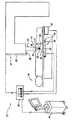
図1及び図2を参照すると、本発明の一つの側面は、誘導放射線療法を、患者16の体14の中の腫瘍のようなターゲット12に施す際に使用できるように構成されたシステム10を提供する。このシステム10により、電離放射線療法を放射線送出源18からターゲットに送出しながら、ターゲット12を患者の体14の中で位置確認し、実際の位置をリアルタイムで監視する。呼吸、器官の充満及び排出、又は他の内部運動のため、ターゲット12は体14の中で移動する。放射線ビームに対してターゲットの運動を追跡し、監視して、ターゲット12への放射線の正確な照射、及び、必要であれば、ターゲットの周りの最小のマージンだけを保証する。本システム10は、腫瘍又は他のターゲットに関する放射線のための誘導放射線療法と関連して以下に説明されるけれども、本システムは、例えば、他の治療目的の又は診断目的で、体内の他のターゲットを追跡し、且つ監視するのに使用することができる。 With reference to FIGS. 1 and 2, one aspect of the present invention is a
図示した実施形態(図1)の放射線送出源18は線形加速器として知られた電離放射線装置であるが、いかなる放射線療法放出装置でもよい。カリフォルニア州パロアルト(Palo Alto)のバリアン・メディカル・システムズ社(Varian Medical Systems, Inc.)、ニュージャージー州イセリン(Iselin)のシーマンス・メディカル・システムズ社(Siemans Medical Systems Inc.)、ニュージャージー州イセリンのエレクタ・インスツルメンツ社(Electa Instruments, Inc.)、又は、日本の三菱電機株式会社によって製造されたこのような装置を含む他の放射線療法放出装置を使用することができる。このような装置は、在来の単部門又は多部門放射線療法、3D等角放射線療法(3D CRT、3D conformal radiation therapy)、逆変調放射線療法(IMRT、inverse modulated radiation therapy)、定位放射線療法(stereotactic radiotherapy)、トモセラピー(tomo therapy)を果たすのに使用される。これは、種々の治療計画ソフトウエアシステムと関連して行われる。 The
放射線送出源18は、ゲートで制御され或いは形成された電離放射線ビーム19を、可動ガントリー20から、ガントリーから離れた位置の点を基準とした領域又は体積に送出する。マシンアイソセンタ22と称される空間内のこの点は、電離放射線19を、産業標準治療計画手順によって決定されるように形成する点である。電離放射線がターゲットに正確に送出されるように、システム10により、ターゲット12をマシンアイソセンタ22に対して正確に位置決めさせることができる。システムによりまた、ターゲットを取り囲む健常組織の付帯的な損傷を最小にするように、放射線療法中、マシンアイソセンタに対するターゲットの実際の位置を監視させることができる。 The
図示したシステム10は、ターゲット12内に又はターゲット12に隣接して位置し、体内のターゲットの実際の位置をマークする、複数のマーカー30を有する。したがって、マーカー30は、体30内、体上又は体30近くのマーカーである。一例では、マーカー30を、治療アイソセンタに対する既知の位置で、患者固定装置に取り付けるのがよい。マーカー30は、患者の体14の外部に位置決めされた励磁源32によって、賦勢され、或いは励磁される。マーカー30が励磁されると、マーカー30は、各々、選択された特有の周波数で共鳴し、体14の外から測定可能な低エネルギーの無線周波数磁気信号を発生させる。マーカー30からの信号は、患者の体14の外部に置かれたセンサー36のアレイ34によって検出され、且つ測定される。センサー36は、互いに対して、一定の選択された幾何学的形態に配置され、その結果、アレイ34は、位置及び運動が計算される一定の基準座標形を構成する。センサー36は、各センサー36から測定情報を受け、且つそのセンサーに対して患者の体14の中のマーカー30の実際の位置を決定するコンピュータ制御装置38に作動的に連結される。 The illustrated
一実施形態では、コンピュータ制御装置38は、共鳴するマーカーからセンサー36による信号測定値に基づいて、ターゲット12内のターゲットアイソセンタ40の位置を定め、これを決定するのに使用されるアルゴリズムを有する。他の実施形態では、ターゲット12内のターゲットアイソセンタ40の位置が選択され、コンピュータ制御装置38は、選択されたターゲットアイソセンタに対する各マーカー30の位置及び/又は向きについての位置情報を利用する。ターゲットアイソセンタ40は、治療計画手順によって決定された通り、成形された放射線線量が配置され又は差し向けられる点又は位置である。一つの実施形態では、センサ36は、センサアレイ34に対して患者の体14の中のターゲットアイソセンタ40の実際の位置を追跡するために、毎分12回以上ポーリングされる。したがって、患者がセンサアレイ34に隣接して位置決めされると、ターゲット12及びターゲットアイソセンタ40の実際の位置をリアルタイムで監視することができる。 In one embodiment, the
ターゲットアイソセンタ40の実際の位置は、センサアレイ34に対するマシンアイソセンタ22の位置と比較される。図示したシステム10は、線形加速器のガントリー20に、又は他の実施形態で使用される放射線療法放出装置の他の選択された位置に位置決めされた基準デバイスを有する。これらの他の実施形態では、他の放射線療法放出装置は、コバルト機械(cobalt machines)、ガンマナイフ(Gamma Knife)、サイバーナイフ(cyberknife)、専門ステレオ定位放射線療法装置(specialized stereostatic radiotherapy devices)、又は、(CTスキャナーに線形加速器を利用する)断層CT組立体(TomoCT assembly)を含む。基準装置42は、マシンアイソセンタ22に対して既知の空間的又は幾何学的関係に位置決めされる。一つの実施形態における基準装置42は、アレイ34のセンサ36によって検出できる測定可能な信号を出す、共鳴する三軸の単一周波数マーカーである。他の実施形態では、基準装置42を、ガントリー20から離れた遠隔位置に配置することができる。いずれの実施形態でも、センサアレイ34に対する基準装置42の位置を決定するときに、センサアレイに対するマシンアイソセンタ22の位置を計算することができる。センサー36は、基準装置42に付いての測定データをコンピュータ制御装置38に与え、コンピュータ制御装置は、センサアレイ34に対するマシンアイソセンタ22の位置を計算する。 The actual position of the
センサアレイ34に対するターゲットアイソセンタ40の位置は、センサアレイに対するマシンアイソセンタ22の位置と比較される。ターゲットアイソセンタ40及びマシンアイソセンタ22が空間的に不整合であり、二つのアイソセンタが互いに三次元的に一致しなければ、患者16及び又はターゲット12を、マシンアイソセンタ22に対して移動させることができる。ターゲット12の位置は、ターゲットアイソセンタ40がマシンアイソセンタ22と一致するまで移動される。一旦、ターゲットアイソセンタ40及びマシンアイソセンタ22が許容可能に整合されると、放射線送出源18を作動して、ターゲットアイソセンタを基準とする電離放射線ビーム19を出し、それによって、ターゲット12を取り囲む健常組織に対して付帯的な損傷を最小にし、或いは排除しながら、ターゲットに放射線療法計画に従って照射することができる。ターゲットアイソセンタがマシンアイソセンタ22に対して許容できない量移動しないようにし、且つ、ターゲットアイソセンタとマシンアイソセンタとが許容変位限度内であるときに治療できるように、ターゲットアイソセンタ40の実際の位置も、放射線療法中、リアルタイムで監視することができる。 The position of the
図示した実施形態では、システム10も、フィードバックデータを、システム及び/又は放射線放出装置18を操作する医師又は技師のためのユーザーインターフェイスに与える、コンピュータ制御装置38に連結された監視組立体44を有する。一例として、監視組立体44は、フィードバックデータを、患者が放射線療法のためにセットアップされ、且つ位置決めされているときに、リアルタイムで、マシンアイソセンタの位置に対する三次元空間内のターゲットアイソセンタの位置の視覚的な表示として与える。監視組立体44はまた、例えば、セットアップ完了の確認、図形情報、患者情報、放射線療法計画の情報、又は誘導放射線療法の工程中に利用可能な他の情報を有する他のフィードバックデータをユーザインタフェースに与えることができる。 In the illustrated embodiment, the
図3乃至図5は、システム10で使用可能な、他の実施形態の励磁可能なマーカー30を示す。図3に示すマーカー30の一つは、導電性巻き線48によって包まれたフェライトコア46を有する埋め込み可能な単一軸の共鳴マーカー31であり、巻き線は小さいコンデンサー50に接続される。マーカー31は、電磁界を発生させる外部励磁源32によって賦勢されるように構成される。この電磁界により、マーカー31を所定の周波数で共鳴させ、それによって、体の外側からセンサー36(図1参照)によって測定されるのに十分な強度の信号を出す。患者に永久的に埋め込むことができる小さい自給式のワイヤレスの励磁可能なマーカー31を提供するために、生物学的に不活性な被覆52がフェライトコア46、巻き線48及びコンデンサー50を包む。この実施形態では、マーカー31は、マーカー信号の発生又は通信のための外部のエネルギー源とワイヤーを介して物理的に接続される必要がないから、マーカー31は「ワイヤレス」である。一つの実施形態では、マーカー31は、約5mmにすぎない長さ、及び、アプリケーター針に嵌るように寸法決めされた直径を有する。他の実施形態では、マーカー31は、マーカー信号の好ましい形成のために、必要に応じて異なる寸法を有することができる。 3-5 illustrate another embodiment of an
図4に最も良く示すように、別の或る励磁マーカー30は、三つのシグナル部分54を有する、三軸のワイヤレス共鳴マーカー52からなる。各シグナル部分54は、他の二つのシグナル部分と垂直な軸線方向に位置決めされる。したがって、三つのシグナル部分54は、X、Y、Z基準座標系を構成する。シグナル部分54の各々は、フェライトコア46と、フェライトコア46の周わりの巻き線48と、各巻き線に接続された小さいコンデンサー50と、を有する。各シグナル部分は、外部励磁源32によって賦勢され、他の二つのシグナル部分の共鳴周波数と異なる周波数で共鳴するように形成される。 As best shown in FIG. 4, another
一つの実施形態では、図4に示すように、三軸マーカー52は生物学的に不活性な被覆56を有し、その結果、マーカーを患者の体内に永久的に埋め込むことができる。マーカー52に外部励磁源32によって賦勢されると、各々のマーカーのシグナル部分が、その選択された周波数で共鳴して、測定可能なマーカー信号を或る強度で出し、その結果、マーカー信号を、センサアレイ34(図1参照)によって各々測定することができる。コンピュータ制御装置による周波数多重化により、コンピュータ制御装置38に、センサアレイに対するマーカーの位置及び向きを計算するときに、マーカーの異なるシグナル部分からのマーカー信号を区別させる。 In one embodiment, as shown in FIG. 4, the
図5に最も良く示すように、他の実施形態のマーカー30は、単一のフェライトコア60と、マーカーについてX、Y及びZ軸線方向を定めるように、互いに垂直な軸線方向に配向された三組の巻き線62と、を有する立方体形状のマーカー58からなる。各巻き線62は、小さいコンデンサー64に接続され、他の二つの巻き線と湖異なる周波数で共鳴するように構成される。したがって、立方体形状のマーカー58も、ワイヤレスの三軸の共鳴マーカーである。 As best shown in FIG. 5, the
一つの実施形態では、ワイヤレスの励磁可能なマーカー30が共鳴して、およそ10kHz乃至200kHz周波数範囲内で測定可能な信号を出す。他の実施形態では、マーカー30を、測定可能で識別可能なマーカー信号を生じさせるために十分な電力を提供するバッテリーのような電源を有する、自給式の動力マーカーである。他の実施形態では、マーカー30は、マーカーに特有のマーカー信号を発生させる選択された電源又は励磁源に電線を介して接続できる「有線」マーカーである。マーカー信号は、周波数の関数(即ち、周波数多重)として、時間の関数、即ち時分割多重として、唯一である。 In one embodiment, the wireless
選択された適用では、単一のマーカー31、好ましくは、単軸マーカーが、ターゲット12内に埋め込まれ、単一の共鳴マーカーからの信号の強度が、センサアレイ34に対してターゲット位置情報を決定するのに使用される。別の実施形態では、二つ、三つ又はそれ以上のマーカーが、ターゲット内又はターゲットに隣接した既知の位置に埋め込まれる。各マーカー30は、他のマーカーに対してその特有の信号を生じさせ、その結果、センサアレイ34は、周波数多重によって、マーカーを区別する。センサアレイ34は、マーカー30からの特有の信号の強度を測定する。信号強度測定値は、(以下により詳細に論ずる)幾何学的な計算に使用するために変換されて、実際の三次元位置(X、Y、Z)と、或いは、センサアレイ34に対してマーカーの角度向き(縦揺れ角、偏揺れ角、横揺れ角)とを正確に決定する。 In the selected application, a single marker 31, preferably a uniaxial marker, is embedded within the
図1を再び参照すると、システム10は、マーカー30を励磁するための磁界を発生させる励磁源32を有する。励磁源は、ターゲット12に対して、選択された位置で、且つ、マーカー30に十分近く位置決めされているので、放出された磁界は、マーカーを良好に賦勢するのに十分な強度を有する。図示した実施形態では、複数のマーカー30が、ターゲット12内に又はターゲット12に隣接してに患者の体14の中に永久的に埋め込まれる。一つの実施形態では、コンピュータ制御装置38は、それぞれのマーカーを選択された周波数で選択的に励磁するように、マーカー30ごとに励磁源32のための別々の駆動回路を提供する。一つの実施形態では、励磁源32は、X、Y及びX軸線方向に三次元磁界を発生させる三次元のAC磁界源である。この励磁源32は、各マーカー30について一つのソースコイルを提供し、ソースコイルを通って駆動された電流が、それぞれのマーカーに同調されたAC磁気波形を発生させる。別の実施形態では、励磁源32中のソースコイルは、それぞれのマーカー30のための多重の又は走査された励磁周波数磁界を発生させるように構成されたコイルによって作られる。 Referring again to FIG. 1, the
図6及び図7は、体の外部に位置決めでき(図6参照)、ターゲットの12の中に、又はその近くに位置決めされたマーカー30から間隔を隔てたセンサアレイ34の概略等角図である。これらの図示した実施形態では、三つのマーカー30が、ターゲット12の中に、又はその近くに埋め込まれて示される。図6に見えるように、センサアレイ34は、複数のセンサ36を基準座標系X、Y又はZに沿って互いに対して一定の既知の幾何学的形態で支持するフレーム70を有する。フレーム70上の各センサ36の位置は基準座標系72に対して固定されて、コンピュータ制御装置38によって使用される測定データを得るための一定の基準点を定める。図6の実施形態では、フレーム70は、センサが単一平面に位置決めされるように、センサ36を支持する。図7の実施形態では、フレーム70は、二つの直交する平面でセンサ36を支持するように形成され、従って、センサ36は、基準座標系72のX、Y及びZ軸に沿って配向される。したがって、センサアレイ34は、測定値が得られる固定基準構造を成し、計算が実行されて、ターゲット12、ターゲットアイソセンタ40及びマシンアイソセンタ22の相対位置が決定される。 6 and 7 are schematic isometric views of a
図6及び図7の図示した実施形態は、「ワイヤレス」マーカー30を利用し、その結果、周波数多重が、異なるマーカーからの信号を識別するのに利用される。各センサ36は、X、Y及びZ軸に対して、マーカー30のそれぞれ一つからの絶対的なマーカー信号強度を測定する三軸センサーである。基準座標系の各軸に沿ったマーカー信号の絶対的な信号強度は、各マーカーのX、Y及びZ位置を決定するために、各マーカーのためのセンサ36によって測定される。 The illustrated embodiments of FIGS. 6 and 7 utilize a “wireless”
磁界の強度は、励磁源からの距離の三乗に比例する割合で減少することが知られている。したがって、センサからのマーカーの距離を、マーカーの信号強度に基づいて決定することができる。マーカーから、互いに既知の位置に隔てられた一連のセンサまでの幾何学的な関係は、一つの特有の解で一連の方程式を解くのに使用される。したがって、マーカー30とセンサ36との間の距離は、それぞれのセンサーによって測定されたマーカーの信号強度に基づいて、コンピュータ制御装置38によって計算され、幾何学上の方程式に対する最も適当な解を求めて繰り返される。 It is known that the strength of the magnetic field decreases at a rate proportional to the cube of the distance from the excitation source. Therefore, the distance of the marker from the sensor can be determined based on the signal strength of the marker. The geometric relationship from the marker to a series of sensors separated from each other at a known position is used to solve a series of equations with one unique solution. Thus, the distance between the
センサアレイ34に対する空間内のマーカー30の正確な位置を、そのマーカーと、アレイの互いに間隔を隔てられた少なくとも四つの別々の三軸センサとの間の距離に基づいて計算することができる。三軸センサからの距離の絶対的な大きさは、三軸大きさの各々(x、y及びz方向)を二乗し、その結果を合計し、最後に、距離の結果について平方根をとることによって決定される。一例として、一つのセンサ36とマーカー30の一つとの間の距離は、球の半径に幾何学的に相当する。図8は、別々のセンサ36によって各々定められた中心点102を有する二つの例示の球100を示す。二つの球100が交差するとき、交差は円104を定める。その結果、マーカーが、その円上の或る点に置かれていることが知られる。図9に示すように、三つの球100が交差するとき、交差は、マーカーがその線上に置かれる、二つの点105のうちの一つを定める。四つの球100が交差するとき、交差は、センサアレイ34に対する空間内のマーカー30の正確な位置に相当する空間内の単一点108を定める。 The exact location of the
ターゲット12内に埋め込まれた単一のマーカー30を使用する実施形態では、センサアレイ34は、空間内のそのマーカーの位置を決定するのに、たった四つの三軸センサ36を含めばよい。信号は周波数多重であり、多重周波数は各センサコイルで受けられ、各個々の周波数成分は、制御電子工学の高速フーリエ変換(first Fourier transform、FFT)で組み合わされた信号を処理することによって調べられので、多重マーカーは同じセンサーで位置確認される。ターゲット12の中又はターゲット12に近接して位置決めされた三つ以上のマーカー30を有する実施形態では、センサアレイ34は、基準座標系72に対して既知の幾何学的な向きに構成され、その結果、三組の三次元データ(単一軸マーカーからのx、y及びz)を使用することによって、基準座標系72に対する空間内の治療体積の角度向き(即ち、縦揺れ角、偏揺れ角、横揺れ角)を計算するために、コンピュータ制御装置38が、マーカー信号の測定値を、使用することができる。ターゲットに対するマーカー30の位置に基づいて、ターゲット12の位置及び角度向きを、コンピュータ制御装置38によって決定することができる。 In embodiments that use a
マーカーの信号を、多くの方法で、信号処理ソフトウエア又は電子装置を経て、励磁源32によって発生された信号から分離するのがよい。一つの実施形態では、励磁源32を「オン」にしてマーカーを励磁し、次いで、「オフ」にして、励磁源からの信号による干渉なしに、マーカーの応答の測定を可能にする。マーカー30は、励磁源32をセンサーの電気的なインダクタンス、容量及び直列抵抗によって決定される期間「オフ」にした後、共鳴し続ける。別の実施形態では、システムは、励磁源32がマーカー30の測定中「オン」のままである連続波(continuous wave、CW)で作動される。マーカー信号は、励磁源からの信号と位相が90°ずれているので、マーカー信号は、励磁信号から取り除かれる。励磁信号の零交差の時間は既知であり、変わらないマーカー信号は、その時間でそのピーク強度であろう。第三実施形態では、励磁源の信号の出力周波数は、マーカーの励磁を最大にするように、連続的に変えられ又は走査され、その結果、不要な励磁信号を最小にし、或いは除去しながら、マーカー信号を最大にする。 The marker signal may be separated from the signal generated by the
ターゲット12及びターゲットアイソセンタ40に対する各マーカーの位置も計算され、或いは決定される。一つの実施形態では、ターゲット12内のターゲットアイソセンタ40は、CTスキャン、MRI、超音波システム、又は、核画像システム(nuclear imaging system)(例えば、陽電子放射断層撮影法)のような、画像システムによって提供された、ターゲットについての画像データに基づいて、最初に選択される。一旦、ターゲットアイソセンタ40が選択されると、埋め込まれた各マーカー30の位置は、ターゲットアイソセンタ40に対して測定される。次いで、ターゲットアイソセンタ40の位置は、基準座標系に対する各マーカーの位置を定めることに基づいて、基準座標系72に対して決定される。 The position of each marker relative to the
別の実施形態では、ターゲットアイソセンタ40は、ターゲット12に対するマーカーの位置の関数として定められる。マーカー30は、ターゲット12中に、又はターゲット12に隣接して選択的に位置決めされ、マーカーの向きは、ターゲットアイソセンタを定め、且つ計算するのに使用される。かくして、たとえマーカー30がターゲット12内に、或いはターゲット12のすく隣にさえ正確に埋め込まれていなくとも、ターゲット12内のターゲットアイソセンタ40を定め、その位置をマーカー30及び基準座標系72に対して決定することができる。しかしながら、ターゲットが移動すれば、ターゲットとマーカーがユニットと一緒に移動するように、マーカー30は、ターゲット12に十分近く位置決めされる。したがって、ターゲットの移動は、センサアレイ34に対するマーカーの移動を追跡をすることによって監視される。 In another embodiment, the
システム10は、リアルタイムで、ターゲット12の移動を追跡するように構成される。ターゲット12及びマーカー30を含む患者の体14の位置がセンサアレイ34に隣接して位置決めされ、且つ、マーカーが賦勢されるとき、コンピュータ制御装置38は、各センサ36からデータを獲得し、結果を毎秒およそ12回出力する。コンピュータ制御装置は、センサ36からの測定データを得て、五秒ごとに、センサアレイに対するターゲットアイソセンタ40の位置を計算する。別の実施形態では、コンピュータ制御装置38は、センサ36を測定して、センサアレイ34に対する特定のターゲットアイソセンタ40の運動をリアルタイムで監視することができる。最新測定速度は、測定ノイズを減じるのに十分なデータ平均化を可能にし、同時に、ユーザにとって十分な更新速度を可能にするように減じられるのがよい。
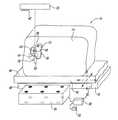
図10は、ガントリー20の下で、センサアレイ34に隣接して、患者の体14を移動可能に支持する支持台76を有する本発明の側面を示す部分等角図である。支持台76は、マシンアイソセンタ22の下に位置決めできる。支持台76は、ターゲットアイソセンタ40がマシンアイソセンタと一致するまで、マシンアイソセンタ22に対する患者16の位置を調節するように移動できる。センサアレイ34は、支持台76の上、支持台76の下、或いは支持台76に置かれ、或いはこれに連結される。変形例として、センサアレイ34を、確認されるべきマーカー30(埋め込まれた、外部の、又は、ガントリーの)に十分に近い位置で、線形加速器のガントリーに取り付けられるのがよい。線形加速器に取り付けられたセンサアレイ34を有するこの変形例では、マシンアイソセンタ22からセンサアレイまでの位置が既知であり、その結果、別体のガントリーマーカー42を使用しなくてもよい。 FIG. 10 is a partial isometric view showing a side view of the present invention having a
図1及び図10に最も良く見えるように、支持台76は、ベース88と、センサアレイ34に対して直線移動及び角移動可能にベースに移動可能に支持されたテーブル上面90と、を有する。マシンアイソセンタ22及びセンサアレイ34に対するテーブル上面及び患者16の移動を制御する移動制御システム78が、テーブル上面90に連結される。移動制御システム78はまたコンピュータ制御装置38に連結され、コンピュータ制御装置38は移動制御システム78を作動して、患者の直線位置又は角位置を調節するようにプログラムされている。一つの実施形態では、テーブル上面の位置は、移動制御システムを作動する、医師、物理学者又は技師のような、許可されたユーザに応答して、或いは、コンピュータ制御装置38によって与えられた指示に応答して自動的に移動する。 As best seen in FIGS. 1 and 10, the
一旦、ターゲットアイソセンタ40がマシンアイソセンタ22と一致するように、ターゲット12が位置決めされると、電離放射線を、ターゲット領域又は体積に直接、選択的に、且つ非常に正確に送出することができる。ターゲット12に対する放射線療法の適用を、ターゲットの周りに必要とされるマージンを潜在的に最小にしながら、正確な精度で選択された線量及び強度で行うことができる。一つの実施形態では、ターゲットアイソセンタ40の実際の位置は、放射線療法を施す間、実質的に連続的に監視され、且つマシンアイソセンタ22に対して追跡される。ターゲットアイソセンタ40が、変位距離の許容範囲を超えてマシンアイソセンタ22から離れるように移動すれば、コンピュータ制御装置38は、信号を放射線療法装置に与えて、ターゲットに対する放射線療法を中断させる。次いで、ターゲットアイソセンタ40がマシンアイソセンタ22と再び一致するまで、ターゲットの位置を手動で又は自動的に調節することができ、そして、放射線療法を再開することができる。一つの実施形態では、コンピュータ制御装置38は、ターゲットアイソセンタ40がマシンアイソセンタ22から移動しても移動距離が許容範囲を超えなければ、コンピュータ制御装置38が放射線療法を中断しないようにプログラムされる。この移動の範囲は、ターゲットの種類(例えば、前立腺、肺、肝臓)、ターゲットの大きさ、ターゲットの位置、ビームの形状/大きさ、及び放射線療法計画のような多くの要因に依存する。 Once the
コンピュータ制御装置38に連結された監視組立体44によって、ターゲットアイソセンタの位置の追跡を容易にする。図11及び図12は、例として、マーカー30、ターゲットアイソセンタ40及びマシンアイソセンタ22の位置について、フィードバックデータをオペレータに提供する監視組立体44のフィードバック部分80を示す。フィードバック部分80は、画像、図形又は玄武情報をオペレータに提供する表示モニターである。
画像フィードバック装置、聴覚フィードバック装置、又は視覚フィードバック装置のような他のフィードバック部分80を、別の実施形態では使用することができる。一つの実施形態では、コンピュータ制御装置38は、体14の中のターゲット12の形状及び大きさを定める、例えば、CT、MRI又は超音波画像システムからの画像データを収容する。
画像データはまた、ターゲット12内の、又はその周わりの各マーカー30の位置を定める。コンピュータ制御装置38は、画像データを使用して、ターゲット、マーカー及びターゲットアイソセンタの模擬モデルを作る。この模擬モデルは、図11に仮想線で示すように、フィードバック部分80に表示される。この模擬モデルはまた、模擬ターゲットアイソセンタ40がマシンアイソセンタと一致するように、マシンアイソセンタ22を重ねて表示される。模擬ターゲット及び模擬マーカーはまた、特定の放射線療法を、ターゲットに適用するために、実際のターゲットをどのように三次元的に位置決めし、且つ配向しなければならないかを表示する。A monitoring
Other feedback portions 80 such as an image feedback device, an audio feedback device, or a visual feedback device may be used in other embodiments. In one embodiment, the
The image data also defines the position of each
監視組立体44も、コンピュータ制御装置38から情報を受けて、これを表示して、マシンアイソセンタ22に対して、模擬ターゲット及び模擬マーカーに対するマーカー30及びターゲットアイソセンタ40の実際の位置を示す。したがって、患者16が支持台76(図1参照)上にいる間に、フィードバック部分80によって、オペレータが、模擬マーカーに対するマーカーの実際の位置、及びマシンアイソセンタ22に対するターゲットアイソセンタ40の実際の位置を、実質的にリアルタイムで決定することを可能にする。患者16及び支持台76を、ターゲット112が選択された放射線療法のために正しく配向されるまで、再位置決めすることができる。 The monitoring
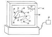
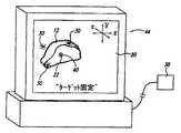
マシンアイソセンタ22に対するターゲット12の位置を正確に追跡し、監視するのに送出して、システム10を、時間中、患者の体14の中の腫瘍等のようなターゲットの状態を監視するのに使用することもできる。図13及び図14は、体92の中の腫瘍90を示す概略図である。腫瘍90内又はそれに近接して永久的に埋め込まれた三つのマーカー30をこの実施形態のために示す。腫瘍90及びマーカー30の画像が、時間の初めから終わりまで、CT、MRI、超音波、又は他の撮像技術によって得られる。これらの腫瘍90及びマーカー30の多重画像から、腫瘍に対するマーカーの位置を比較し、追跡することができる。したがって、医師は、多重画像中のマーカー30を、腫瘍が患者の体内で縮み、生長し、移動し、或るはそうではなく変化したのかどうかを決定する基準ツールとして使用することができる。 Dispatched to accurately track and monitor the position of the
一例として、図13は、三つのマーカー30の埋め込んだ、第一条件の腫瘍90の画像を示し、図14は、もっと後の時間に得られた腫瘍の第二の画像を示す。第二の画像は、患者の体内の同じ位置に同じマーカーを示し、マーカーに対する腫瘍の位置から、人は、腫瘍が縮んだことが分かる。かくして、医師は、例えば、放射線療法の効果、追加の治療が必要か否か、或いは、腫瘍の生長の変化が起こったか否か、或いは、放射線治療計画を変更する必要があるか否かを決定する時間の初めから終わりまで、体内の腫瘍又は他のターゲットの状態を追跡することができる。 As an example, FIG. 13 shows an image of a
上述の実施形態では、マーカー30は、ターゲット12内に、又はそのすく隣の皮下に埋め込まれているとして説明され図示されている。このマーカー30の埋め込みは、ターゲット12が移動すれば、マーカーがユニットとしてターゲットと一緒に移動するようにすることが必要とされる場合に行われる。図15及び図16に示す別の実施形態では、マーカーは、体内又は体上で、ターゲット12に実質的に隣接し、且つこれと整列して、患者の体14の外表面112に接着された表面取付マーカー110である。表面取付マーカー110を、ターゲット12に対して、体の外表面112上の実質的に固定した位置に、テープ等のような粘着剤で、取り外し自在に接着することができる。これらの表面取付マーカー110は、外表面に対して体14内で実質的に移動することが知られていないターゲット12に特に適している。表面取付マーカー30はまた、体14の中のターゲットの大きさ又は位置が、ターゲットアイソセンタの幾らかの運動が、効果的な放射線療法又は治療に重要でないような場合の使用に適している。したがって、表面取付マーカー110は、ターゲット12及びマシンアイソセンタ22の正確な整合及び向きのための基準点をなす。変形例として、マーカー30を、治療アイソセンタに対して既知の位置で患者を固定する装置上に又はその中に取り付けてもよい。 In the embodiments described above, the
一つの実施形態での表面取付マーカー110は、ワイヤレスマーカーであり、その結果、ターゲット12に対するマーカー110の位置を乱すことなく、患者16が治療領域に行ったり来たりすることができるように、放射線線治療期間後、マーカーを患者の体14上に接着されたままにすることができる。変形例では、マーカー110は、患者16に接着されたままであり、治療領域の「有線」マーカーシステムのリード線に接続可能である。マーカーを患者の体上の適所に固定したまま、患者16を治療領域から去らせるために、配線をマーカー110から離すことができる。 The
表面取付マーカー110はまた、放射線治療プログラム中、患者の基線胴回り(前後及び横寸法)を監視するのに使用できる。患者のセパレータと称される、基線胴回り測定値は、CT、MRI又は物理的な測定によって最初に得られる。患者のセパレータは、その患者のための放射線治療計画を準備するときに使用される。化学療法又は放射線療法中に起こるかもしれない患者のセパレータの変化についてのデータを提供するために、表面取付マーカー100を単独で、又は、埋め込んだマーカーと組み合わせて利用することができる。各表面取付マーカー110は、例えばターゲットアイソセンタ又は互いに、空間内の識別可能な最初の位置を有する。センサアレイ34及びコンピュータ制御装置38は、各表面取付マーカー及び/又はターゲットアイソセンタの間の距離を決定するように形成される。コンピュータ制御装置38は、患者のセパレータに対応して、距離を計算し、監視する。放射線療法の進行中、例えば、化学療法又は放射線療法による実質的な体重の減少のために、患者のセパレータが著しく変化すれば、より少ない患者の組織が放射線ビームを交替するのに利用でき、それにより、計画した放射線量より高い結果となるため、治療計画は妥当でなくなる。 The
一つの実施形態では、表面取付マーカー110を、放射線治療操作前及び/又は操作中に、患者のセットアップ操作を容易にし、かつ早くするのに使用することができる。表面取付マーカー110を、既知の位置で、患者の体14上の選択された位置に位置決めする。マーカー110を励磁して、センサアレイに対する位置を決定する。次いで、マーカーの位置情報を、患者の外皮膚と線形加速器又はテーブル上面との間の距離である、ターゲット皮膚距離又は線源皮膚距離を計算するのに使用することができる。マーカー110をまた、テーブル上面から、マーカー又は患者の皮膚に投影されたレーザー従事線のような他の整合手段までの間の距離である、テーブル上面からアイソセンタまでを決定するのに使用することができる。したがって、患者が放射線治療計画に従って適正に位置決めされているかどうかを速やかに決定するために、セットアップ操作中、表面取付マーカー110を、関連した距離を自動的に計算するのに使用することができる。 In one embodiment, the
別の実施形態では、表面取付マーカー110を、ターゲット12の中に又はその近くに埋め込まれた一つ以上のマーカー30と共に使用することができる。各マーカー110又は30の相対的な位置を、上述のような患者のセットアップ、ターゲットの位置確認、ターゲットの位置決め、ターゲットの移動の追跡、及び/又はターゲットの持ち上げの任意の組み合わせのために計算し、使用することができる。 In another embodiment, the
システム10はまた、放射線療法を施す前に、患者の自動セットアップ操作に使用するようになっている。一つの実施形態の自動セットアップ操作を、図17のフローチャートとして、概略的に示す。患者のこのセットアップ操作において、患者の体の中の腫瘍又は他のターゲットを識別する(ブロック150参照)。例えば、X線、CT、MRI、核又は超音波撮像によって、ターゲットの画像を得る(ブロック152参照)。次いで、医師及び/又は技師は、特定の腫瘍について治療計画を決定する(ブロック154参照)。一つ以上のマーカーを、ターゲットに対して選択された位置で、体の中に又は体上に付け(ブロック156参照)、そして、マーカーに対する治療アイソセンタの位置を決定し、或いは計算する(ブロック158参照)。 The
ターゲット及びマーカーをセンサアレイにほぼ隣接するように、患者を可動支持台上に位置決めする(ブロック160参照)。励磁源を作動して、マーカーを賦勢し(ブロック162参照)、センサが、マーカーからの信号の強度を測定する(ブロック164参照)。コンピュータ制御装置は、センサアレイ及びマシンアイソセンタに対するマーカー及びターゲットアイソセンタの位置を計算する(ブロック166参照)。コンピュータは、ターゲットアイソセンタとマシンアイソセンタの位置を比較し(ブロック168参照)、そして、二つのアイソセンタが不整合ならば、コンピュータは、支持台の制御システムを自動的に作動して、ターゲットアイソセンタがマシンアイソセンタと一致するまで、テーブル上面をマシンアイソセンタに対して移動させる(ブロック170参照)。 The patient is positioned on the movable support so that the target and marker are substantially adjacent to the sensor array (see block 160). The excitation source is activated to activate the marker (see block 162) and the sensor measures the intensity of the signal from the marker (see block 164). The computer controller calculates the marker and target isocenter positions relative to the sensor array and machine isocenter (see block 166). The computer compares the position of the target isocenter and the machine isocenter (see block 168), and if the two isocenters are misaligned, the computer automatically activates the support control system so that the target isocenter is machine The table top is moved relative to the machine isocenter until it coincides with the isocenter (see block 170).
一つの実施形態では、コンピュータ制御装置はまた、模擬マーカーの位置及び向きに対するマーカーの位置及び向きを決定する。マーカーが模擬マーカーと適切に整合も配向もされていなければ、支持テーブルは、適切なマーカーの整合に必要とされるように、直線的に及び角度的に調節される。このマーカーの整合は、6次元、即ち、X、Y、Z、(縦揺れ角、偏揺れ角、横揺れ角)に沿ったターゲット体積を正確に位置決めする。したがって、患者は、放射線療法をターゲットに正確に送出するために、マシンアイソセンタに対して正確な位置に自動的に位置決めされる。 In one embodiment, the computer controller also determines the marker position and orientation relative to the simulated marker position and orientation. If the marker is not properly aligned or oriented with the simulated marker, the support table is adjusted linearly and angularly as required for proper marker alignment. This marker alignment accurately positions the target volume along six dimensions, ie, X, Y, Z (pitch angle, yaw angle, roll angle). Thus, the patient is automatically positioned at the correct position with respect to the machine isocenter in order to accurately deliver radiation therapy to the target.
この自動セットアップ操作の一つの実施形態では、ターゲットアイソセンタがマシンアイソセンタと一致するまで、コンピュータは、放射線放出装置が放射線ビームを発するのを制止する。コンピュータは、放射線治療を施す間、ターゲットアイソセンタの位置を監視する(ブロック172参照)。ターゲットアイソセンタの位置が転位の許容度又は許容範囲を超えていれば、コンピュータは、放射線アイソセンタの放出を中断する(ブロック174参照)。次いで、コンピュータは、ターゲットがターゲットアイソセンタと共に好ましく位置決めされ、且つマシンアイソセンタと一致し(ブロック176参照)、放射線療法を、ターゲットの連続照射のために再び作動することができる(ブロック178参照)ように、テーブル上面及び患者を(ユニットとして)自動的に再位置決めすることができる。放射線療法の放出が未だ完了されていなければ(ブロック180参照)、操作は、参照ブロック172に戻って、放射線が送出されるときに、マシンアイソセンタに対するターゲットの位置を監視する。したがって、ターゲットの周囲に大きなマージンを必要とすることなく、放射線がターゲットに正確に送出されるように、調節が自動的に行われる。 In one embodiment of this automatic setup operation, the computer stops the radiation emitting device from emitting a radiation beam until the target isocenter coincides with the machine isocenter. The computer monitors the position of the target isocenter while performing radiation therapy (see block 172). If the position of the target isocenter exceeds the dislocation tolerance or tolerance, the computer interrupts the radiation isocenter emission (see block 174). The computer then allows the target to be preferably positioned with the target isocenter and coincides with the machine isocenter (see block 176), and radiation therapy can be activated again for continuous irradiation of the target (see block 178). The table top and patient can be automatically repositioned (as a unit). If the radiation therapy release has not yet been completed (see block 180), operation returns to reference block 172 to monitor the position of the target relative to the machine isocenter as radiation is delivered. Thus, adjustments are made automatically so that the radiation is delivered accurately to the target without requiring a large margin around the target.
本発明の特定の実施形態及び例を、例示の目的でここに説明したけれども、当業者にとって容易に認識されるように、本発明の精神及び範囲を逸脱することなく、種々の同等の変形を行うことができる。本発明の側面の個々に提供された教示は、体内でターゲットを位置確認し、監視し、且つ追跡するのに適用することができ、上述のように、体内の腫瘍の例示の放射線治療に必ずしも限定されない。 Although particular embodiments and examples of the invention have been described herein for purposes of illustration, various equivalent modifications may be made without departing from the spirit and scope of the invention, as will be readily appreciated by those skilled in the art. It can be carried out. The individually provided teachings of aspects of the present invention can be applied to locate, monitor, and track a target within the body, and as described above, are not necessarily for exemplary radiation treatment of tumors in the body. It is not limited.
一般的に、特許請求の範囲では、使用された用語を、本発明を明細書及び特許請求の範囲に開示された特定の実施形態に限定するように解釈するべきではないが、体内の選択されたターゲットの位置を位置確認、監視し、及び/又は追跡するために、装置及び方法を提供するための特許請求の範囲に従って作動する全てのターゲット位置確認及び監視システムを含むように解釈すべきである。したがって、本発明は、特許請求の範囲によるのを除いて、限定されない。 In general, the terms used in the claims should not be construed to limit the invention to the specific embodiments disclosed in the specification and the claims, but are selected in the body. Should be construed to include all target localization and monitoring systems operating in accordance with the claims for providing apparatus and methods for locating, monitoring and / or tracking the location of the target. is there. Accordingly, the invention is not limited except as by the appended claims.
体内に埋め込まれ、励磁源によって励磁されて、前記複数のセンサーによって測定可能な特有のマーカー信号を生じることができる複数のマーカーを更に有する、請求項1記載のターゲット位置確認追跡システム。 The target localization tracking system of claim 1, further comprising a plurality of markers that are implanted in the body and can be excited by an excitation source to produce unique marker signals that can be measured by the plurality of sensors.
前記複数のマーカーは、少なくとも三つのマーカーを含む、請求項2記載のターゲット位置確認追跡システム。 The target location tracking system according to claim 2, wherein the plurality of markers includes at least three markers.
前記マーカーは、各々互いに軸線方向に並んでいない、請求項3記載のターゲット位置確認追跡システム。 The target position confirmation tracking system according to claim 3, wherein the markers are not arranged in the axial direction.
各マーカーからのマーカー信号は、他のマーカー信号の周波数と異なる特有の周波数を有する、請求項2記載のターゲット位置確認追跡システム。 The target localization tracking system of claim 2, wherein the marker signal from each marker has a unique frequency that is different from the frequency of the other marker signals.
前記マーカーは、体内に埋め込めるワイヤレスマーカーである、請求項1記載のターゲット位置確認追跡システム。 The target localization tracking system according to claim 1, wherein the marker is a wireless marker that can be implanted in a body.
前記データ演算ユニットは、前記センサーに対するターゲットの位置を決定するように構成される、請求項6記載のターゲット位置確認追跡システム。 The target location tracking system of claim 6, wherein the data computing unit is configured to determine a position of the target relative to the sensor.
前記マーカーは、体内に永久的に埋め込めるように構成される、請求項1記載のターゲット位置確認追跡システム。 The target location tracking system of claim 1, wherein the marker is configured to be permanently implanted in the body.
前記マーカーは、単軸共鳴マーカーである、請求項1記載のターゲット位置確認追跡システム。 The target position confirmation tracking system according to claim 1, wherein the marker is a uniaxial resonance marker.
前記マーカーは、ワイヤレスマーカーである、請求項1記載のターゲット位置確認追跡システム。 The target location tracking system according to claim 1, wherein the marker is a wireless marker.
前記基準デバイスは、マシンアイソセンタに対して一定位置にあり、前記センサーのうちの少なくとも二つによって測定可能な基準信号を発する、請求項1記載のターゲット位置確認追跡システム。 The target location tracking system of claim 1, wherein the reference device is in a fixed position relative to a machine isocenter and emits a reference signal measurable by at least two of the sensors.
前記データ演算ユニットは、(a)前記マシンアイソセンタに対する前記センサーの位置、及び(b)前記センサーに対するマーカーの位置を決定して、前記マシンアイソセンタに対する前記ターゲットの位置を決定するように構成される、請求項1記載のターゲット位置確認追跡システム。 The data computing unit is configured to determine (a) the position of the sensor relative to the machine isocenter, and (b) the position of the marker relative to the sensor, to determine the position of the target relative to the machine isocenter. The target position confirmation tracking system according to claim 1.
前記マーカーから遠隔にあって、前記マーカーにエネルギーを与える磁界を発生させるように構成された励磁源を更に有する、請求項1記載のターゲット位置確認追跡システム。 The target location tracking system of claim 1, further comprising an excitation source remote from the marker and configured to generate a magnetic field that energizes the marker.
前記複数のセンサは、単一平面内のベースに固定されて、センサアレイを形成する、請求項1記載のターゲット位置確認追跡システム。 The target location tracking system of claim 1, wherein the plurality of sensors are secured to a base in a single plane to form a sensor array.
体を支持するように成形され、且つ寸法決めされた患者支持構造体を更に有し、前記複数のセンサは、前記患者支持構造体に取り付けられる、請求項1記載のターゲット位置確認追跡システム。 The target localization tracking system of claim 1, further comprising a patient support structure shaped and dimensioned to support a body, wherein the plurality of sensors are attached to the patient support structure.
前記テーブル構造体は、ベースとテーブル上面とを有し、前記ベースは、前記センサーに対して一定位置にあり、前記テーブル上面は、前記センサーに対して移動可能に調節できる、請求項15記載のターゲット位置確認追跡システム。 16. The table structure according to claim 15, wherein the table structure has a base and a table upper surface, the base is in a fixed position with respect to the sensor, and the table upper surface is movably adjustable with respect to the sensor. Target location tracking system.
前記データ演算ユニットに接続された監視システムを更に有し、前記監視システムは、互いに対するターゲット及びマシンアイソセンタの位置についてのフィードバック情報を提供するように構成されたフィードバック部分を有する、請求項1記載のターゲット位置確認追跡システム。 The system of claim 1, further comprising a monitoring system coupled to the data computing unit, the monitoring system having a feedback portion configured to provide feedback information about the position of the target and machine isocenter relative to each other. Target location tracking system.
前記フィードバック部分は、表示装置である、請求項17記載のターゲット位置確認追跡システム。 18. The target location tracking system of claim 17, wherein the feedback portion is a display device.
データ演算ユニット及び監視システムは、互いに対するターゲット及びマシンアイソセンタの移動を、リアルタイムで識別し且つ表示するように構成される、請求項17記載のターゲット位置確認追跡システム。 The target location tracking system of claim 17, wherein the data computing unit and the monitoring system are configured to identify and display in real time the movement of the target and machine isocenter relative to each other.
前記マーカーは、互いに軸線方向に並んでいない複数のマーカーのうちの一つであり、データ演算ユニットは、前記複数のセンサー及びマシンアイソセンタに対するターゲットの三次元空間の位置及び向きを識別するように構成される、請求項1記載のターゲット位置確認追跡システム。 The marker is one of a plurality of markers that are not axially aligned with each other, and the data calculation unit is configured to identify a position and orientation of a target in a three-dimensional space with respect to the plurality of sensors and the machine isocenter. The target location tracking system of claim 1.
前記基準デバイスは、放射線療法送出機械に取付可能な少なくとも一つの励磁可能なマーカーであり、一つの励磁可能なマーカーが、基準信号を生じさせる、請求項1記載のターゲット位置確認追跡システム。 The target location tracking system of claim 1, wherein the reference device is at least one excitable marker attachable to a radiation therapy delivery machine, wherein the one excitable marker generates a reference signal.
前記基準デバイスは、前記複数のセンサ及びデータ演算ユニットに物理的に接続されず、前記基準デバイスと前記センサーとの間に、ワイヤレス相互接続が設けられる、請求項1記載のターゲット位置確認追跡システム。 The target location tracking system of claim 1, wherein the reference device is not physically connected to the plurality of sensors and a data computing unit, and a wireless interconnect is provided between the reference device and the sensor.
放射線をマシンアイソセンタに対して治療体積に送出する放射線療法送出源と共に使用できるターゲット位置確認監視システムであって、
互いに対して、及びターゲットに対して既知の幾何学的形態で体上に、及び/又は体内に固定可能であり、外部励磁源によって励磁されて、前記マーカーによる識別可能なマーカー信号を生じさせる複数のワイヤレスマーカーと、
前記マーカーからのマーカー信号を測定するように位置決めされ、前記マーカーのうちの一つ以上のためにマーカー測定信号を出すように形成された複数のセンサーを有するセンサアレイと、
放射線送出源及びマシンアイソセンタに対して選択した位置に位置決め可能な基準デバイスと、
前記センサーに連結されて、前記センサーからマーカー測定信号を受け、マーカー測定信号を使用して、前記マシンアイソセンタに対するターゲットの位置を決定するように構成されたデータ演算ユニットと、を含む、ターゲット位置確認監視システム。A target localization monitoring system that can be used with a radiation therapy delivery source that delivers radiation to a treatment volume relative to a machine isocenter,
A plurality that is fixable on the body and / or in the body in a known geometric form with respect to each other and with respect to the target, and is excited by an external excitation source to produce an identifiable marker signal by the marker With wireless markers,
A sensor array having a plurality of sensors positioned to measure a marker signal from the marker and configured to emit a marker measurement signal for one or more of the markers;
A reference device positionable at a selected position relative to the radiation delivery source and the machine isocenter;
A data computation unit coupled to the sensor and configured to receive a marker measurement signal from the sensor and to use the marker measurement signal to determine a position of the target relative to the machine isocenter. Monitoring system.
各マーカーからの信号は測定可能であり、各センサは、マーカーのうちの少なくとも一つからの信号を測定し、コンピュータ制御装置は、測定された信号に基づいて、体内のターゲットの位置及び/又は空間的な向きを決定する、請求項23記載のターゲット位置確認監視装置。 The signal from each marker is measurable, each sensor measures the signal from at least one of the markers, and the computer controller can determine the location of the target in the body and / or based on the measured signal The target position confirmation monitoring apparatus according to claim 23, wherein a spatial orientation is determined.
前記マーカーから遠隔にあって、前記マーカーを賦勢する励磁界を作動するように構成された励磁源を更に有する、請求項23記載のターゲット位置確認監視システム。 24. The target location monitoring system of claim 23, further comprising an excitation source remote from the marker and configured to activate an excitation field that energizes the marker.
前記センサアレイは、前記マーカーから遠隔の選択された位置にユニットとして位置決め可能であり、前記センサーは平面上に配列される、請求項23記載のターゲット位置確認監視システム。 24. The target location monitoring system of claim 23, wherein the sensor array is positionable as a unit at a selected location remote from the marker, and the sensors are arranged on a plane.
体を支持するように形成され且つ寸法決めされた患者支持構造体を更に有し、複数のセンサは、前記患者支持構造体の部分に対して一定位置にある、請求項23に記載のターゲット位置確認監視システム。 24. The target position of claim 23, further comprising a patient support structure configured and dimensioned to support the body, wherein a plurality of sensors are in a fixed position relative to a portion of the patient support structure. Confirmation monitoring system.
前記コンピュータ制御装置に連結された監視システムを更に有し、前記監視システムは、互いに対する、ターゲット及びマシンアイソセンタの位置についてのフィードバック情報を提供するように構成されたフィードバック部分を有する、請求項23記載のターゲット位置確認監視システム。 24. A monitoring system coupled to the computer controller, the monitoring system further comprising a feedback portion configured to provide feedback information about the position of the target and machine isocenter relative to each other. Target location monitoring system.
前記フィードバック部分は、表示装置である、請求項28記載のターゲット位置確認監視システム。 29. The target location confirmation monitoring system according to claim 28, wherein the feedback part is a display device.
前記コンピュータ制御装置及び監視システムは、互いに対するターゲット及びマシンアイソセンタの移動をリアルタイムで識別し、且つ、伝えるように構成される、請求項28記載のターゲット位置確認監視システム。 30. The target location monitoring system of claim 28, wherein the computer controller and the monitoring system are configured to identify and communicate in real time the movement of the target and machine isocenter relative to each other.
体内のターゲットに照射する放射線療法送出システムであって、
放射線を、放射線療法送出源から、前記放射線療法送出源から間隔を隔てたマシンアイソセンタに送出する放射線送出組立体と、
ターゲットに対して或る位置で体の中に及び/又は体の上に固定可能で、外部励磁源によって励磁されて、測定可能なマーカー信号を生じさせることができるマーカーと、
互いから間隔を隔てられ、互いに既知の幾何学的形態に配列され、マーカー信号を測定し、マーカー信号に関する測定信号を発生させるように構成された複数のセンサと、
前記マシンアイソセンタに対して位置決めされ、前記マシンアイソセンタに対する前記センサーの位置を決定するように構成された基準デバイスと、
前記センサーに連結され、マーカー測定信号を受け、マーカー測定信号を使用して、前記ターゲットが前記マシンアイソセンタから所望の距離内にあるか否かを決定するように構成されるデータ演算ユニットと、を有する放射線送出システム。A radiation therapy delivery system for irradiating a target in the body,
A radiation delivery assembly for delivering radiation from a radiation therapy delivery source to a machine isocenter spaced from the radiation therapy delivery source;
A marker that can be fixed in and / or on the body at a position relative to the target and can be excited by an external excitation source to produce a measurable marker signal;
A plurality of sensors spaced from each other and arranged in a known geometric form with respect to each other, configured to measure a marker signal and generate a measurement signal for the marker signal;
A reference device positioned relative to the machine isocenter and configured to determine a position of the sensor relative to the machine isocenter;
A data computing unit coupled to the sensor and configured to receive a marker measurement signal and to use the marker measurement signal to determine whether the target is within a desired distance from the machine isocenter; A radiation delivery system having.
体内に埋め込み可能な複数のマーカーを更に有し、各マーカーは、外部励磁源源によって励磁されて、前記複数のセンサーによって測定可能なマーカー信号を生じさせることができる、請求項31記載の放射線送出システム。 32. The radiation delivery system of claim 31, further comprising a plurality of markers implantable in the body, wherein each marker can be excited by an external excitation source to produce a marker signal measurable by the plurality of sensors. .
各マーカーからのマーカー信号は、他のマーカーとなる特有の信号である、請求項32記載の放射線送出システム。 33. The radiation delivery system of
各マーカー信号は、他のマーカー信号の周波数と異なる周波数を有する、請求項32記載の放射線送出システム。 33. The radiation delivery system of
マーカー信号は、或る信号強度を有し、前記データ演算ユニットは、マーカー信号に基づいてマーカー及びターゲットアイソセンタの空間的な位置を計算する、請求項31記載の放射線送出システム。 32. The radiation delivery system of claim 31, wherein the marker signal has a signal strength and the data computing unit calculates a spatial position of the marker and target isocenter based on the marker signal.
基準デバイスは、前記放射線送出組立体に取り付けられ、センサーによって測定可能な基準信号を出す、請求項31記載の放射線送出システム。 32. The radiation delivery system of claim 31, wherein a reference device is attached to the radiation delivery assembly and provides a reference signal that can be measured by a sensor.
前記基準デバイスは、複数のセンサーによって測定可能な信号を出し、前記データ演算ユニットは基準デバイスに連結可能であり、前記データ演算ユニットは、基準信号の測定値に基づいて、複数のセンサーに対するマシンアイソセンタの位置を識別するように構成される、請求項31記載の放射線送出システム。 The reference device generates a signal that can be measured by a plurality of sensors, and the data operation unit can be coupled to the reference device, and the data operation unit can perform machine isocentering for the plurality of sensors based on the measurement value of the reference signal. 32. The radiation delivery system of claim 31, wherein the radiation delivery system is configured to identify a position.
体の外に位置決めでき、マーカーを励磁してマーカー信号を生じさせるように構成された励磁源を更に有する、請求項31記載の放射線送出システム。 32. The radiation delivery system of claim 31, further comprising an excitation source that can be positioned outside the body and configured to excite the marker to produce a marker signal.
前記複数のセンサは、マーカーに対してユニットとして位置決め可能なセンサアレイを構成する、請求項31記載の放射線送出システム。 32. The radiation delivery system of claim 31, wherein the plurality of sensors constitute a sensor array that can be positioned as a unit relative to a marker.
マーカーが埋め込まれる体を支持するように形成され、且つ寸法決めされた患者支持構造体を更に有し、前記センサは、前記患者支持構造体の一部分に対して一定位置に取り付けられる、請求項31記載の放射線送出システム。 32. Further comprising a patient support structure configured and dimensioned to support a body into which a marker is implanted, wherein the sensor is mounted in a fixed position relative to a portion of the patient support structure. The radiation delivery system described.
前記患者支持構造は、ベースと、ターゲットをマシンアイソセンタと一致して位置決めするために前記センタに対して移動可能に調節可能なテーブル上面と、を有する、請求項31記載の放射線送出システム。 32. The radiation delivery system of claim 31, wherein the patient support structure includes a base and a table top that is movably adjustable relative to the center to position the target in alignment with the machine isocenter.
前記データ演算ユニットに連結され、且つ、互いに対するマシンアイソセンタとターゲットの位置についてのフィードバック情報を提供するように構成されたフィードバック部分を有する監視システムを更に有する、請求項31記載の放射線送出システム。 32. The radiation delivery system of claim 31, further comprising a monitoring system coupled to the data computing unit and having a feedback portion configured to provide feedback information about machine isocenter and target positions relative to each other.
前記マーカーは複数のマーカーのうちの一つであり、前記マーカーは、各々互いに軸線方向に並んでおらず、前記コンピュータ制御装置は、前記複数のセンサーに対するターゲットの三次元空間の位置及び向きを計算するように構成されている、請求項31記載の放射線送出システム。 The marker is one of a plurality of markers, and the markers are not aligned with each other in an axial direction, and the computer controller calculates a position and orientation of a target in a three-dimensional space with respect to the plurality of sensors. 32. The radiation delivery system of claim 31, wherein the radiation delivery system is configured to:
前記基準デバイスは、前記放射線療法送出源に取り付けられたワイヤレスの励磁可能なマーカーである、請求項31記載の放射線送出システム。 32. The radiation delivery system of claim 31, wherein the reference device is a wireless excitable marker attached to the radiation therapy delivery source.
前記放射線療法送出組立体は、強度調節放射線療法(intensity modulated radiation therapy、IMRT)システム、三次元等角外部ビーム放射線システム(three-dimensional conformal external beam radiation system)、定位放射線外科システム(stereotactic radiosurgery system)、断層治療(tomo therapy)及び小源照射療法(brachytherapy)システムの一つである、請求項31記載の放射線送出システム。 The radiation therapy delivery assembly includes an intensity modulated radiation therapy (IMRT) system, a three-dimensional conformal external beam radiation system, a stereotactic radiosurgery system. 32. The radiation delivery system of claim 31, which is one of tomo therapy and brachytherapy systems.
前記データ演算ユニットは、前記マーカーの位置、及び前記ターゲットの位置及び向きを識別する視覚的な診断用データを含み、前記データ演算ユニットは、前記ターゲットに放射線療法を適用する前に、視覚的な診断用データと、前記複数のセンサーに対する体内の前記ターゲットの位置及び空間的な向きとを比較し、且つ、前記ターゲット内のターゲットアイソセンタを識別するように構成されている、請求項31記載の放射線送出システム。 The data calculation unit includes visual diagnostic data that identifies the position of the marker and the position and orientation of the target, and the data calculation unit is configured to display the visual therapy before applying radiation therapy to the target. 32. Radiation according to claim 31, configured to compare diagnostic data with the position and spatial orientation of the target in the body relative to the plurality of sensors and to identify a target isocenter within the target. Delivery system.
電離放射線を体内の選択されたターゲットに送出する放射線療法システムであって、
電離放射線を前記ガントリーから離れた遠隔位置の治療アイソセンタに送出する移動可能なガントリーと、
体内でターゲットに対する或る位置に固定でき、共鳴器と、その共鳴器を入れるカプセルとを有し、前記共鳴器は、外部の磁界によって励磁されて、体内に或る間測定可能なマーカー信号を生じさせることができるワイヤレスマーカーと、
既知の幾何学的形態に配列され、マーカー信号を測定し、且つ測定信号を出すように構成された複数のセンサーと、
前記センサーに連結され、測定信号を受け、測定信号を使用して、前記治療アイソセンタに対して前記ターゲットの位置を決定させる指示を有するコンピュータ制御装置と、を含む、放射線療法システム。A radiation therapy system that delivers ionizing radiation to selected targets in the body,
A movable gantry for delivering ionizing radiation to a remote treatment isocenter remote from the gantry;
It can be fixed at a certain position with respect to the target in the body, and has a resonator and a capsule for containing the resonator. Wireless markers that can be generated,
A plurality of sensors arranged in a known geometric configuration and configured to measure a marker signal and to generate a measurement signal;
And a computer controller coupled to the sensor, receiving a measurement signal and having instructions for causing the treatment isocenter to determine the position of the target using the measurement signal.
マーカーが埋め込まれた体を支持するように構成され且つ寸法決めされた患者支持構造体を更に有し、前記センサは、前記患者支持構造の部分に対して共通の平面に取り付けられる、請求項47記載の放射線療法システム。 48. A patient support structure configured and dimensioned to support a body in which a marker is implanted, wherein the sensor is mounted in a common plane relative to a portion of the patient support structure. The described radiation therapy system.
コンピュータ制御装置に連結された監視システムを更に有し、前記監視システムは、互いに対する、治療アイソセンタ及びターゲットの位置についてのフィードバック情報を提供するように構成されたフィードバック部分を有する、請求項47記載の放射線療法システム。 48. The system of claim 47, further comprising a monitoring system coupled to the computer controller, the monitoring system having a feedback portion configured to provide feedback information about the treatment isocenter and target position relative to each other. Radiation therapy system.
前記コンピュータ制御装置及び監視システムは、互いに対するターゲット及びマシンアイソセンタの移動をリアルタイムで識別し、且つ表示するように構成される、請求項49記載の放射線療法システム。 50. The radiation therapy system of claim 49, wherein the computer controller and the monitoring system are configured to identify and display movement of the target and machine isocenter relative to each other in real time.
前記コンピュータ制御装置は、前記マーカーの位置、及び、ターゲットの位置及び向きを識別する画像データを含み、前記コンピュータ制御装置は、画像データと、前記複数のセンサーに対する体内のターゲットの位置及び空間的な向きとを比較し、ターゲット内のターゲットアイソセンタを識別するように構成される、請求項49記載の放射線療法システム。 The computer controller includes image data that identifies the position of the marker and the position and orientation of the target, and the computer controller includes the image data and the position and spatial position of the target in the body relative to the plurality of sensors. 50. The radiation therapy system of claim 49, configured to compare the orientation and identify a target isocenter within the target.
選択された線量の放射線を体内の選択されたターゲットに送出する放射線送出源と共に使用可能な放射線ターゲット整合システムであって、
前記ターゲットに対する選択された位置に、体内に及び/又は体の上に付けることができ、励磁源によって励磁されて、体内に測定可能な信号を生じさせることができるマーカーと、
ターゲット及び体内に位置決めされたマーカーの画像データを得て、且つ、その画像データを使用して、体内での空間的な関係及び向きを有する模擬ターゲットモデルを構成するように構成された画像システムと、
互いに対して既知の幾何学的形態で間隔を隔てられ、且つ、体内の前記マーカーからの信号を識別するように位置決めされ、前記マーカーからのマーカー信号を測定し、マーカー測定信号を出すように構成された複数のセンサと、
前記センサーに連結されて、前記センサーからの測定信号を受け、測定信号及び画像データを使用して、(a)前記複数のセンサーに対する体内の前記ターゲットの実際の位置のターゲットモデルを決定し、(b)前記ターゲット内のターゲットアイソセンタを識別し、(c)ターゲットモデルと、ターゲットの放射線治療の準備に当たって模擬ターゲットモデルとを比較し、且つ整合させる指示を含むデータ演算ユニットと、を有する、放射線ターゲット整合システム。A radiation target alignment system usable with a radiation delivery source that delivers a selected dose of radiation to a selected target in the body,
A marker that can be applied to and / or on the body at a selected location relative to the target and can be excited by an excitation source to produce a measurable signal in the body;
An image system configured to obtain image data of targets and markers positioned in the body and to use the image data to construct a simulated target model having a spatial relationship and orientation in the body; ,
Spaced from each other in a known geometric form and positioned to identify a signal from the marker in the body, configured to measure the marker signal from the marker and issue a marker measurement signal A plurality of sensors,
Coupled to the sensor, receiving a measurement signal from the sensor, and using the measurement signal and image data, (a) determining a target model of an actual position of the target in the body relative to the plurality of sensors; a radiation target comprising: b) identifying a target isocenter within said target; and (c) a data computing unit including instructions for comparing and matching the target model with a simulated target model in preparation for target radiation therapy. Alignment system.
前記マーカーは、体に取付け可能な複数のマーカーのうちの一つであり、マーカーは、互いに特有の信号を発生させる、請求項52記載の放射線ターゲット整合システム。 53. The radiation target alignment system of
前記マーカーは、複数のマーカーのうちの一つであり、前記マーカーは、各々互いに軸線方向に並んでおらず、前記データ演算ユニットは、前記複数のセンサーに対するターゲットの三次元空間の位置並びに向きを識別するように構成される、請求項52記載の放射線ターゲット整合システム。 The marker is one of a plurality of markers, and the markers are not aligned with each other in the axial direction, and the data calculation unit determines a position and orientation of a target in a three-dimensional space with respect to the plurality of sensors. 53. The radiation target matching system of
放射線を体内の選択されたターゲットに送出する放射線送出システムと共に使用し、放射線は、放射線送出源から間隔を隔てたマシンアイソセンタに送出される、調節可能な患者支持組立体であって、
ベースと、
前記ベースに取り付けられた支持構造体と、
前記支持構造体及び/又は前記ベースによって支持され、互いに既知の幾何学的形態に配列され、体内のターゲットに対して選択された位置で体内に埋め込み可能な励磁可能なマーカーからの信号を測定し、信号測定データを出すように構成された複数のセンサーを有するセンサアレイと、、
さらに、前記センサーに連結されて、信号測定データを受け、信号測定データを使用して、前記ターゲットの位置を決定するように構成されたデータ演算ユニットと、
前記支持構造に連結されて、前記支持構造体を選択的に移動させ、前記データ演算ユニットに連結されて、前記ターゲットを前記マシンアイソセンタと一致して位置決めするように、前記データ演算ユニットからの情報に応答して移動可能である移動制御デバイスと、を有する、調節可能な患者支持組立体。An adjustable patient support assembly for use with a radiation delivery system for delivering radiation to a selected target within the body, wherein the radiation is delivered to a machine isocenter spaced from the radiation delivery source,
Base and
A support structure attached to the base;
Measure signals from excitable markers supported by the support structure and / or the base and arranged in a known geometric configuration relative to each other and implantable in the body at selected locations relative to the body target. A sensor array having a plurality of sensors configured to emit signal measurement data;
A data computing unit coupled to the sensor for receiving signal measurement data and using the signal measurement data to determine the position of the target;
Information from the data computing unit coupled to the support structure to selectively move the support structure and coupled to the data computing unit to position the target in alignment with the machine isocenter. An adjustable patient support assembly having a movement control device movable in response to
放射線送出源からターゲットに放射線を当てるために、体内の選択されたターゲットを識別し、追跡する方法であって、
マーカー信号を生じさせるように、外部励磁源によって励磁可能であるマーカーを、ターゲットに対して体内に埋め込むステップと、
前記埋め込んだマーカーを前記外部励磁源で励磁して、マーカー信号を生じさせるステップと、
前記センサは、互いに対して既知の幾何学的形態に位置決めされ、マーカー信号に応答して測定信号を発生させる体外のセンサーでマーカー信号を測定するステップと、
前記センサーからの測定信号を使用して、前記ターゲットに対するマシンアイソセンタの位置を決定するステップと、
前記ターゲットが前記マシンアイソセンタと一致した状態で、前記放射線送出装置に対して体を位置決めするステップと、
放射線を、前記放射線送出装置から、前記マシンアイソセンタ及び前記ターゲットに当てるステップと、を有する方法。A method of identifying and tracking a selected target in the body for irradiating the target from a radiation delivery source, comprising:
Implanting a marker in the body with respect to the target that can be excited by an external excitation source to generate a marker signal;
Exciting the embedded marker with the external excitation source to generate a marker signal;
Measuring the marker signal with an extracorporeal sensor that is positioned in a known geometric form relative to each other and that generates a measurement signal in response to the marker signal;
Using a measurement signal from the sensor to determine a position of the machine isocenter relative to the target;
Positioning the body relative to the radiation delivery device with the target aligned with the machine isocenter;
Applying radiation from the radiation delivery device to the machine isocenter and the target.
さらに、複数のマーカーを、前記ターゲットに対して選択した位置及び向きで体内に埋め込むステップを有し、各マーカーは、前記外部励磁源によって励磁されて、それぞれのマーカーに特有の識別可能なマーカー信号を生じさせることができ、
さらに、前記埋め込んだマーカーを前記外部励磁源で励磁させて、識別可能な特有のマーカー信号を生じさせるステップと、
前記埋め込んだマーカーの各々からのマーカー信号を、体の外部の前記センサーで測定するステップと、
体内の前記ターゲット内の前記ターゲットアイソセンタの位置を、前記マーカー信号の前記センサーによる測定値に基づいて決定するステップと、を有する、請求項56記載の方法。Further, the method includes a step of embedding a plurality of markers in the body at a selected position and orientation with respect to the target, and each marker is excited by the external excitation source and is identifiable marker signal specific to each marker. Can give rise to
Further, exciting the embedded marker with the external excitation source to generate a distinguishable unique marker signal;
Measuring a marker signal from each of the embedded markers with the sensor outside the body;
57. The method of
前記センサーに対する体内のターゲットの位置及び向きを決定するステップを更に有する、請求項56記載の方法。 57. The method of
前記マーカーは、或る信号強度を有するマーカー信号を発生させ、マーカー信号を測定するステップは、マーカー強度を各センサーで測定するステップを含む、請求項56記載の方法。 57. The method of
コンピュータ制御装置に連結された監視システムを提供するステップと、
互いに対するマシンアイソセンタ及びターゲットアイソセンタの位置についての、前記コンピュータ制御装置からのフィードバックを、前記監視システムに与えるステップと、を更に有する、請求項56記載の方法。Providing a monitoring system coupled to a computer controller;
57. The method of
前記監視システムは、表示装置部分を含み、フィードバックを提供することは、前記表示装置部分に、互いに対するターゲット及びマシンアイソセンタの位置の視覚的な表示を提供することを含む、請求項60記載の方法。 61. The method of
少なくとも三つのマーカーを、前記ターゲットに対して選択された位置で体内に埋め込むステップを更に有し、前記少なくとも三つのマーカーの各々は、互いに軸線方向に並んでいない、請求項56記載の方法。 57. The method of
前記放射線送出源にほぼ隣接して選択された位置に、体を位置決めするステップを更に有し、その場合、
マーカー信号を測定し、前記ターゲットアイソセンタの位置を決定し、マシンアイソセンタの位置を決定し、かつ、前記ターゲットアイソセンタが前記マシンアイソセンタと一致するように、体を前記放射線送出装置に対して位置決めしすることが、体が前記放射線送出装置にほぼ隣接して選択された位置に位置決めされる前に、リアルタイムで行われる、請求項56記載の方法。Further comprising positioning the body at a selected position substantially adjacent to the radiation delivery source, wherein
Measure the marker signal, determine the position of the target isocenter, determine the position of the machine isocenter, and position the body relative to the radiation delivery device so that the target isocenter coincides with the machine isocenter 57. The method of
前記ターゲットの照射中、前記マシンアイソセンタに対するターゲットアイソセンタの位置をリアルタイムで監視するステップと、前記ターゲットアイソセンタが前記マシンアイソセンタとの整合から外れて移動すれば、前記ターゲットの照射を中断するステップと、を更に有する、請求項56記載の方法。 Monitoring the position of the target isocenter relative to the machine isocenter in real time during the irradiation of the target, and interrupting the irradiation of the target if the target isocenter moves out of alignment with the machine isocenter. 57. The method of
放射線療法を体内の選択されたターゲットに施す方法であって、
リード線なしのマーカーを、前記ターゲットに対して選択された位置で体内に埋め込むステップと、
前記埋め込んだマーカーを、体外の励磁源で励磁して、識別可能なマーカー信号を生じさせるステップと、
前記埋め込んだマーカーからのマーカー信号を、体の外部に、互いに既知の幾何学的形態で位置決めされたセンサーで測定するステップと、
マーカー信号の測定値に基づいて、放射線送出組立体のマシンアイソセンタに対するターゲットの位置を決定するステップと、
前記ターゲットが前記マシンアイソセンタと一致するように、前記放射線送出装置に対して体を位置決めするステップと、
放射線を、前記放射線送出装置から前記ターゲット及び前記マシンアイソセンタに当てるステップと、
放射線をターゲットに当てている間、前記マシンアイソセンタに対する前記ターゲットの実際の位置をリアルタイムで監視するステップと、を有する方法。A method of applying radiation therapy to selected targets in the body,
Implanting a marker without a lead in the body at a selected location relative to the target;
Exciting the embedded marker with an external excitation source to produce an identifiable marker signal;
Measuring a marker signal from the embedded marker with sensors positioned in a known geometric form with respect to each other outside the body;
Determining the position of the target relative to the machine isocenter of the radiation delivery assembly based on the measurement of the marker signal;
Positioning a body relative to the radiation delivery device such that the target coincides with the machine isocenter;
Directing radiation from the radiation delivery device to the target and the machine isocenter;
Monitoring in real time the actual position of the target relative to the machine isocenter while applying radiation to the target.
電離放射線を選択したターゲットに送出するための治療上の作業を確立するための放射線治療計画方法であって、
体内の選択したターゲットの画像データを得るステップと、
励磁可能なマーカーを、ターゲットに対して選択された位置で体内に埋め込むステップと、
前記埋め込んだマーカーを外部励磁源で励磁して、体内に前記マーカーによる識別可能なマーカー信号を生じさせるステップと、
前記埋め込んだマーカーからのマーカー信号を、互いに既知の幾何学的形態に位置決めされた複数のセンサーで測定するステップと、
前記画像データから、体内のターゲットの前記ターゲットの形状及び空間的な向きを決定するステップと、
マーカー信号の前記センサーによる測定値に基づいて、体内の前記ターゲット内のターゲットアイソセンタを決定するステップと、
前記ターゲットの形状及び空間的な向きに基づいて、前記ターゲットに照射するための放射線線量及び送出の計画案を開発するステップと、を有する、方法。A radiotherapy planning method for establishing therapeutic work for delivering ionizing radiation to a selected target comprising:
Obtaining image data of a selected target in the body;
Implanting an excitable marker in the body at a selected location relative to the target;
Exciting the embedded marker with an external excitation source to produce a marker signal identifiable by the marker in the body;
Measuring a marker signal from the embedded marker with a plurality of sensors positioned in a known geometric form relative to each other;
Determining from the image data the shape and spatial orientation of the target in the body;
Determining a target isocenter within the target in the body based on a measurement of a marker signal by the sensor;
Developing a radiation dose and delivery plan for irradiating the target based on the shape and spatial orientation of the target.
体を、体内のターゲット及び埋め込まれたマーカーで、放射線送出組立体に対して選択された位置に位置決めするステップを更に有し、前記放射線送出組立体は、集束した放射線を、前記放射線送出組立体から間隔を隔てられたターゲットアイソセンタに選択的に送出するように形成され、
さらに、前記複数のセンサーに対するマシンアイソセンタの位置を決定するステップと、
前記ターゲットが前記マシンアイソセンタ実質的に一致して、前記放射線送出装置に対して体を位置決めするステップと、
放射線を、前記放射線送出組立体から前記マシンアイソセンタに、及び前記ターゲットに送出するステップと、を有する、請求項66記載の方法。The method further comprises positioning a body at a selected position relative to the radiation delivery assembly with a target within the body and an implanted marker, the radiation delivery assembly delivering the focused radiation to the radiation delivery assembly. Configured to selectively deliver to a target isocenter spaced from
Further, determining a position of a machine isocenter relative to the plurality of sensors;
Positioning the body relative to the radiation delivery device with the target substantially coincident with the machine isocenter;
68. The method of claim 66, comprising delivering radiation from the radiation delivery assembly to the machine isocenter and to the target.
前記画像データに基づいて体に対して選択された位置及び向きで、三次元模擬ターゲットモデルを決定するステップと、
マーカー信号の測定値に基づいて、三次元の実際のターゲットを定めるステップと、
模擬ターゲットモデル及び実際のターゲットモデルの位置及び向きについてのフィードバック情報を出すフィードバックデバイスを提供するステップと、
放射線をターゲットに送出する前に、ターゲットと実際のモデルの向きを整合させるように体を移動させるステップと、を更に有する、請求項66記載の方法。Determining a three-dimensional simulated target model at a position and orientation selected with respect to the body based on the image data;
Determining a three-dimensional actual target based on the measurement of the marker signal;
Providing a feedback device for providing feedback information about the position and orientation of the simulated target model and the actual target model;
68. The method of claim 66, further comprising the step of moving the body to align the orientation of the target and the actual model prior to delivering radiation to the target.
放射線を体内のターゲットに送出するために、放射線送出装置に対して体を位置決めする方法であって、
体を移動可能な支持組立体上に位置決めするステップと、
励磁可能なマーカーを、体の外部励磁源で励磁するステップとを有し、前記マーカーは、前記ターゲットに対して選択した位置で体内に埋め込まれ、励磁した前記マーカーは、識別可能なマーカー信号を出し、
さらに、前記埋め込んだマーカーからのマーカー信号を、互いに対して、且つ前記支持組立体に対して既知の幾何学的形態に位置決めされた、体の外部の複数のセンサーで測定するステップと、
さらに、マーカー信号のセンサからの信号に基づいて、体内の前記ターゲット内にターゲットアイソセンタを決定するステップと、
前記放射線送出組立体の位置に基づいて、複数のセンサーに対するマシンアイソセンタの位置を決定するステップと、
前記ターゲットアイソセンタの位置と前記マシンアイソセンタの位置とを比較するステップと、
前記マシンアイソセンタに対して体を移動させて、前記ターゲットアイソセンタを前記マシンアイソセンタと一致して位置決めするステップと、を有する方法。A method of positioning a body with respect to a radiation delivery device for delivering radiation to a target within the body comprising:
Positioning the body on a movable support assembly;
Exciting an excitable marker with an external excitation source of the body, wherein the marker is embedded in the body at a selected position relative to the target, the excited marker receiving an identifiable marker signal broth,
Measuring the marker signal from the implanted marker with a plurality of sensors external to the body positioned in a known geometric configuration relative to each other and to the support assembly;
Further, determining a target isocenter in the target in the body based on a signal from the marker signal sensor;
Determining a position of a machine isocenter relative to a plurality of sensors based on the position of the radiation delivery assembly;
Comparing the position of the target isocenter and the position of the machine isocenter;
Moving the body relative to the machine isocenter to position the target isocenter in alignment with the machine isocenter.
前記複数のセンサは共通の平面に在り、前記マーカーは、共鳴励磁界に応答して共鳴磁気信号を生じさせるリード線なしのマーカーからなる、請求項69記載の方法。 70. The method of claim 69, wherein the plurality of sensors are in a common plane and the marker comprises a leadless marker that produces a resonant magnetic signal in response to a resonant excitation field.
放射線ビームをビームアイソセンタに向ける放射源を有する放射線送出システムを使用する放射線療法における、患者内の治療ターゲットを位置確認し、追跡するための装置であって、
前記治療ターゲットに対して或る部位で患者に埋め込まれるように構成されたワイヤレスのマーカーと、
前記マーカーの位置及び/又は向きについての位置情報を得るセンサーと、
前記センサーに作動的に連結されたコンピュータと、を有し、前記コンピュータは、(a)放射線ビームで患者の少なくとも或る部分に照射し、(b)患者に照射しながら、前記センサーを使用して、前記マーカーの特性を検知し、(c)前記マーカーの検知された特性に基づいて、前記治療ターゲットの実際の位置を決定し、(d)患者が前記センサーに最も近い間、前記治療ターゲットの実際の位置を前記ビームアイソセンタとほぼ相関させるフィードバック情報を提供する方法をコンピュータに実行させる指示を含むコンピュータ作動可能媒体を有する、装置。An apparatus for locating and tracking a treatment target in a patient in radiation therapy using a radiation delivery system having a radiation source that directs a radiation beam to a beam isocenter,
A wireless marker configured to be implanted in a patient at a site relative to the treatment target;
A sensor for obtaining position information about the position and / or orientation of the marker;
A computer operatively coupled to the sensor, the computer using (a) irradiating at least a portion of the patient with a radiation beam and (b) irradiating the patient while using the sensor. Detecting a characteristic of the marker; (c) determining an actual position of the treatment target based on the detected characteristic of the marker; and (d) while the patient is closest to the sensor, the treatment target An apparatus having a computer operable medium including instructions for causing a computer to perform a method of providing feedback information that substantially correlates the actual position of the beam with the beam isocenter.
放射線ビームをビームアイソセンタに向ける放射源を有する放射線送出システムを使用する放射線療法における、患者を追跡するための装置であって、
患者に埋め込まれるように構成されたワイヤレスのマーカーと、
前記マーカーの位置及び/又は向きについての位置情報を得るセンサーと、
前記センサーに作動的に連結されたコンピュータと、を有し、前記コンピュータは、(a)前記マーカーの特性を検知して、前記マーカーの位置に関する位置情報を得て、(b)位置情報に基づいて、前記マーカーの実際の位置を決定し、患者が、前記ターゲットの位置情報を得るセンサーに最も近い間に、前記マーカーの実際の位置のフィードバックを提供する方法をコンピュータに実行させる指示を含むコンピュータ作動可能媒体を有する、装置。An apparatus for tracking a patient in radiation therapy using a radiation delivery system having a radiation source that directs a radiation beam to a beam isocenter comprising:
A wireless marker configured to be implanted in a patient;
A sensor for obtaining position information about the position and / or orientation of the marker;
A computer operatively coupled to the sensor, wherein the computer (a) senses the characteristics of the marker to obtain position information regarding the position of the marker, and (b) based on the position information. A computer comprising instructions to determine the actual position of the marker and to cause the computer to execute a method of providing feedback of the actual position of the marker while the patient is closest to the sensor that obtains the position information of the target. An apparatus having an operable medium.
放射線ビームをビームアイソセンタに差し向ける放射源を有する放射線送出システムを使用する放射線療法における、患者内を追跡するための装置であって、
患者に埋め込まれるように構成されたワイヤレスのマーカーと、
前記マーカーの位置及び/又は向きについての位置情報を得るセンサーと、
前記センサーに作動的に連結されたコンピュータと、を有し、前記コンピュータは、(a)前記マーカーの特性を検知して、前記マーカーの位置に関する位置情報を得て、(b)位置情報に基づいて、前記マーカーの実際の位置を決定し、前記マーカーを検知している間に、前記マーカーの移動を追跡する仕方で、前記マーカーの実際の位置のフィードバックを提供する方法をコンピュータに実行させる指示を含むコンピュータ作動可能媒体を有する、装置。An apparatus for tracking within a patient in radiation therapy using a radiation delivery system having a radiation source that directs a radiation beam to a beam isocenter,
A wireless marker configured to be implanted in a patient;
A sensor for obtaining position information about the position and / or orientation of the marker;
A computer operatively coupled to the sensor, wherein the computer (a) senses the characteristics of the marker to obtain position information regarding the position of the marker, and (b) based on the position information. Instructions to determine the actual position of the marker and to cause the computer to perform a method of providing feedback of the actual position of the marker in a manner that tracks movement of the marker while detecting the marker. An apparatus having a computer operable medium comprising:
放射線ビームを生じさせる放射源、患者支持体、及び前記患者支持体を移動させる駆動システムを有する放射線送出システムに関連して使用するための制御システムであって、 治療ターゲットに対して或る部位で患者に埋め込まれるように構成されたワイヤレスのマーカーと、
前記マーカーの位置及び/又は向きについての位置情報を得るセンサーと、
前記センサーに作動可能に連結されたコンピュータと、を有し、前記コンピュータは、(a)前記マーカーを検知して、前記マーカーの実際の位置に関する位置情報を得て、(b)前記マーカーの位置情報に基づいて、前記治療ターゲットの実際の位置を決定し、(c)前記治療ターゲットの実際の位置に基づいて、三次元での前記治療ターゲットと前記放射線ビームのビームアイソセンタとの間のずれを計算し、(d)前記治療ターゲットと前記ビームアイソセンタとの間のずれが、許容範囲を超えている場合に、患者支持台を自動制御によって移動させる方法を前記コンピュータに実行させる指示を含むコンピュータ作動可能媒体を有する、制御システム。A control system for use in connection with a radiation delivery system having a radiation source for producing a radiation beam, a patient support, and a drive system for moving the patient support, the method comprising: A wireless marker configured to be implanted in a patient;
A sensor for obtaining position information about the position and / or orientation of the marker;
A computer operably coupled to the sensor, wherein the computer (a) detects the marker to obtain position information regarding the actual position of the marker, and (b) the position of the marker. Based on the information, determining an actual position of the treatment target; and (c) determining a deviation between the treatment target and the beam isocenter of the radiation beam in three dimensions based on the actual position of the treatment target. Computer operation comprising: (d) instructions for causing the computer to execute a method of moving a patient support by automatic control when a deviation between the treatment target and the beam isocenter exceeds an acceptable range A control system having a possible medium.
放射線ビームを生じさせる放射源、患者支持体、及び前記患者支持体を移動させる駆動システムを有する放射線送出システムに関連して使用するための制御システムであって、 治療ターゲットに対して或る部位で患者に埋め込まれるように構成されたワイヤレスのマーカーと、
前記マーカーの位置及び/又は向きについての位置情報を得るセンサーと、
前記センサーに作動可能に連結されたコンピュータと、を有し、前記コンピュータは、前記ワイヤレスのマーカーを前記センサーによって検知することができるように、患者が前記患者支持体上に置かれている間に、前記コンピュータに、方法を実行させる指示を含むコンピュータ作動可能媒体を有し、前記方法は、(a)前記ワイヤレスマーカーの位置及び/又は向きについての位置情報を前記センサーから得て、(b)前記センサーから得られた前記位置情報に基づいて、前記治療ターゲットの実際の位置を決定し、(c)前記治療ターゲットと前記放射線ビームのビームアイソセンタとの間のずれ量を計算し、(d)前記治療ターゲットと前記ビームアイソセンタとの間の計算されたずれ量に基づいて、コンピュータにより、前記患者支持体を自動的に移動させ、且つ/又、前記放射線ビームを制御するのを含む、制御システム。A control system for use in connection with a radiation delivery system having a radiation source for producing a radiation beam, a patient support, and a drive system for moving the patient support, the method comprising: A wireless marker configured to be implanted in a patient;
A sensor for obtaining position information about the position and / or orientation of the marker;
A computer operably coupled to the sensor, wherein the computer is placed on the patient support so that the wireless marker can be detected by the sensor. Having a computer operable medium including instructions to cause the computer to perform the method, the method comprising: (a) obtaining position information about the position and / or orientation of the wireless marker from the sensor; and (b) Determining an actual position of the treatment target based on the position information obtained from the sensor; (c) calculating a deviation amount between the treatment target and a beam isocenter of the radiation beam; (d) Based on the calculated amount of deviation between the treatment target and the beam isocenter, the computer Automatically moving the bearing member, and / or, including controlling the radiation beam, the control system.
放射線ビームを生じさせる放射源、患者支持体及び前記患者支持体を移動させる駆動システムを有する放射線送出システムに関連して使用するための制御システムであって、
治療ターゲットに対して或る部位で患者に埋め込まれるように形成されたワイヤレスのマーカーと、
前記マーカーの位置及び/又は向きについての位置情報を得るセンサーと、
前記センサーに作動可能に連結されたコンピュータと、を有し、前記コンピュータは、(a)前記マーカーを検知して、前記マーカーの実際の位置に関する位置情報を得て、(b)前記マーカーの検知された位置情報に基づいて、前記マーカーの実際の位置を決定し、(c)前記マーカーを検知しながら、前記マーカーの実際の位置に基づいて、コンピュータによって患者及び/又は患者の移動を自動的に処理するために、放射線ビームを制御する方法を前記コンピュータに実行させる指示を含むコンピュータ作動可能媒体を有する、制御システム。A control system for use in connection with a radiation delivery system having a radiation source producing a radiation beam, a patient support and a drive system for moving the patient support,
A wireless marker configured to be implanted in a patient at a site relative to a treatment target;
A sensor for obtaining position information about the position and / or orientation of the marker;
A computer operably coupled to the sensor, wherein the computer (a) detects the marker to obtain position information regarding the actual position of the marker, and (b) detects the marker. (C) automatically detecting a patient and / or patient movement by a computer based on the actual position of the marker while detecting the marker; A control system comprising a computer operable medium including instructions for causing the computer to perform a method of controlling a radiation beam for processing.
放射線ビームをビームアイソセンタに差し向ける放射線デバイスにおける放射線療法のために患者を調整するための装置であって、
ターゲットに対して患者に埋め込まれるように構成されたワイヤレスマーカーと、
前記マーカーを前記センサーによって検知することができ、且つ前記放射線ビームが患者を照射することができるように、患者を位置決めするように形成された台及びその台を移動させる駆動システムとを有する移動可能な患者支持体と、
コンピュータ作動可能な指示を有するコンピュータを有し、前記指示は、(a)前記マーカーの位置情報を検出し、(b)前記位置情報を使用して、基準フレームに対する前記マーカーの位置を決定し、(c)前記マーカーの位置と前記マーカーに対する所望のマーカーの位置との間のずれ量を計算し、その場合、前記マーカーが所望のマーカー位置に在るときに、前記ターゲットは前記基準フレーム内の所望の原位置に位置決めされる方法を前記コンピュータに実行させる、装置。An apparatus for conditioning a patient for radiation therapy in a radiation device that directs a radiation beam to a beam isocenter,
A wireless marker configured to be implanted in a patient relative to a target;
A movable having a platform configured to position the patient and a drive system that moves the platform so that the marker can be detected by the sensor and the radiation beam can illuminate the patient Patient support,
A computer having computer operable instructions, the instructions comprising: (a) detecting position information of the marker; (b) determining the position of the marker with respect to a reference frame using the position information; (C) calculating the amount of deviation between the position of the marker and the position of the desired marker with respect to the marker, in which case the target is within the reference frame when the marker is at the desired marker position; An apparatus for causing the computer to execute a method of being positioned at a desired original position.
放射線ビームをビームアイソセンタに差し向ける放射線デバイスにおける放射線療法のために患者を調整するための装置であって、
ターゲットに対して患者に埋め込まれるように構成されたワイヤレスマーカーと、
前記マーカーを前記センサーによって検知することができ、且つ前記放射線ビームが患者を照射することができるように、患者を位置決めするように構成された台及びその台を移動させる駆動システムとを有する移動可能な患者支持体と、
コンピュータ作動可能な指示を有するコンピュータと、を有し、前記指示は、(a)前記マーカーの位置情報を検出し、(b)前記マーカーの位置情報を使用して、基準フレームに対するターゲットの位置を決定し、(c)前記基準フレーム内の、前記ターゲットの位置と前記ターゲットの所望の位置との間のずれ量を計算する方法を前記コンピュータに実行させる、装置。An apparatus for conditioning a patient for radiation therapy in a radiation device that directs a radiation beam to a beam isocenter,
A wireless marker configured to be implanted in a patient relative to a target;
A movable having a platform configured to position the patient and a drive system that moves the platform so that the marker can be detected by the sensor and the radiation beam can illuminate the patient Patient support,
A computer having a computer operable instruction, wherein the instruction (a) detects position information of the marker and (b) uses the position information of the marker to determine a position of the target with respect to a reference frame. And (c) causing the computer to execute a method of calculating a deviation amount between the position of the target and the desired position of the target in the reference frame.
放射線ビームをビームアイソセンタに差し向ける放射線デバイスにおける放射線療法のために患者を調整するための装置であって、
ターゲットに対して患者に埋め込まれるように構成されたワイヤレスマーカーと、
前記マーカーを前記センサーによって検知することができ、且つ前記放射線ビームが患者を照射することができるように、患者を位置決めするように構成された台とその台を移動させる駆動システムとを有する移動可能な患者支持体と、
コンピュータ作動可能な指示を有するコンピュータと、を有し、前記指示は、(a)前記マーカーを検知して、前記マーカーの位置に関する位置情報を得て、(b)位置情報に基づいて、前記マーカーの実際の位置を決定し、(c)前記ターゲットと前記ビームアイソセンタとの間のずれ量が許容範囲を超えているならば、前記マーカー実際の位置に従って患者を移動させ、(d)前記検知及び決定作業を繰り返すことによって、前記ビームアイソセンタに対して前記ターゲットを追跡する方法を前記コンピュータに実行させる、装置。An apparatus for conditioning a patient for radiation therapy in a radiation device that directs a radiation beam to a beam isocenter,
A wireless marker configured to be implanted in a patient relative to a target;
A movable having a platform configured to position the patient and a drive system that moves the platform so that the marker can be detected by the sensor and the radiation beam can illuminate the patient Patient support,
A computer having instructions operable by a computer, the instructions comprising: (a) detecting the marker to obtain position information on the position of the marker; and (b) based on the position information, the marker (C) if the amount of deviation between the target and the beam isocenter exceeds an acceptable range, move the patient according to the actual position of the marker, and (d) detect and An apparatus for causing the computer to execute a method of tracking the target with respect to the beam isocenter by repeating a determination operation.
放射線ビームをビームアイソセンタに向ける放射線デバイスにおける放射線療法のために患者を調整するための装置であって、
ターゲットに対して患者に埋め込まれるように構成されたワイヤレスマーカーと、
前記マーカーを前記センサーによって検知することができ、且つ前記放射線ビームが患者を照射することができるように、患者を位置決めするように構成された台とその台を移動させる駆動システムとを有する移動可能な患者支持体と、
コンピュータ作動可能な指示を有するコンピュータと、を有し、前記指示は、(a)前記マーカーを検知して、前記マーカーの位置に関する位置情報を得て、(b)位置情報に基づいて、前記マーカーの実際の位置を決定し、(c)前記マーカーの実際の位置に従って患者を移動させて、前記ターゲットと前記ビームアイソセンタとの間のずれ量を減じ、(d)患者を移動させながら、前記検知及び決定作業を繰り返すことによって、患者の移動中、前記ビームアイソセンタに対して前記ターゲットを追跡する方法を前記コンピュータに実行させる、装置。An apparatus for conditioning a patient for radiation therapy in a radiation device that directs a radiation beam to a beam isocenter,
A wireless marker configured to be implanted in a patient relative to a target;
A movable having a platform configured to position the patient and a drive system that moves the platform so that the marker can be detected by the sensor and the radiation beam can illuminate the patient Patient support,
A computer having instructions operable by a computer, the instructions comprising: (a) detecting the marker to obtain position information on the position of the marker; and (b) based on the position information, the marker (C) moving the patient according to the actual position of the marker to reduce the amount of deviation between the target and the beam isocenter, and (d) moving the patient And an apparatus for causing the computer to perform a method of tracking the target relative to the beam isocenter during patient movement by repeating the determination operation.
放射線ビームをビームアイソセンタに差し向ける放射線デバイスにおける放射線療法のために患者を調整するための装置であって、
ターゲットに対して患者に埋め込まれるように構成されたワイヤレスマーカーと、
前記マーカーを前記センサーによって検知することができ、且つ前記放射線ビームが患者を照射することができるように、患者を位置決めするように構成された台とその台を移動させる駆動システムとを有する移動可能な患者支持体と、
コンピュータと、を有し、該コンピュータは、(a)基準フレームに対して前記ターゲットの所望の原位置のターゲット座標を含むメモリーと、(b)(i)三次元マーカー座標を決定し、(ii)前記三次元マーカー座標に基づいて前記ターゲットの実際の位置を計算し、(iii)前記ターゲットの実際の位置とターゲット座標との間の三次元のずれ量を計算する方法を前記コンピュータに実行させるコンピュータ作動可能な指示を含む、装置。An apparatus for conditioning a patient for radiation therapy in a radiation device that directs a radiation beam to a beam isocenter,
A wireless marker configured to be implanted in a patient relative to a target;
A movable having a platform configured to position the patient and a drive system that moves the platform so that the marker can be detected by the sensor and the radiation beam can illuminate the patient Patient support,
A computer comprising: (a) a memory including target coordinates of a desired original position of the target relative to a reference frame; (b) (i) determining three-dimensional marker coordinates; (ii) ) Calculating an actual position of the target based on the three-dimensional marker coordinates; and (iii) causing the computer to execute a method of calculating a three-dimensional deviation amount between the actual position of the target and the target coordinates. A device containing computer operable instructions.
放射線ビームをビームアイソセンタに向ける放射線デバイスにおける放射線療法のために患者を調整するための装置であって、
ターゲットに対して患者に埋め込まれるように構成されたワイヤレスマーカーと、
前記マーカーを前記センサーによって検知することができ、且つ前記放射線ビームが患者を照射することができるように、患者を位置決めするように構成された台とその台を移動させる駆動システムとを有する移動可能な患者支持体と、
コンピュータと、を有し、該コンピュータは、(a)前記ビームアイソセンタに対する前記ターゲットの所望の原位置を含むメモリー、及び、(b)(i)前記センサーから得られた前記マーカーの位置情報に基づいて、三次元マーカー座標を決定し、(ii)三次元マーカー座標と前記マーカーに対する所望のマーカー位置との間のずれ量を計算し、その場合に前記マーカーが前記所望のマーカー位置に位置決めされているときに、前記ターゲットを前記所望の原位置に位置決めする方法をコンピュータに実行させるコンピュータ作動可能な指示を含む、装置。An apparatus for conditioning a patient for radiation therapy in a radiation device that directs a radiation beam to a beam isocenter,
A wireless marker configured to be implanted in a patient relative to a target;
A movable having a platform configured to position the patient and a drive system that moves the platform so that the marker can be detected by the sensor and the radiation beam can illuminate the patient Patient support,
And (a) a memory including a desired original position of the target with respect to the beam isocenter, and (b) (i) based on position information of the marker obtained from the sensor. Determining a three-dimensional marker coordinate, and (ii) calculating a deviation amount between the three-dimensional marker coordinate and a desired marker position with respect to the marker, in which case the marker is positioned at the desired marker position. An apparatus comprising computer operable instructions for causing a computer to perform a method of positioning the target in the desired home position when in operation.
Claims (29)
Translated fromJapanese前記治療ターゲットに対してある部位で患者内に埋め込まれるように構成されたワイヤレスマーカーを有し、前記ワイヤレスマーカーは、前記患者の外部に配置された励起源によって賦活又は励起され、
前記ワイヤレスマーカーの位置及び配向の一方又は双方についての配置情報を得る、互いに対して固定され既知の幾何学的配置を採る複数のセンサであって、前記複数のセンサは前記患者から離間した固定基準構造に二つの平面内に配置されたセンサと、
前記センサに作動的に接続されたコンピュータとを有し、前記コンピュータは、当該コンピュータに、(a)毎分12回以上、前記センサから配置情報データを受けさせ、(b)前記治療ターゲットの実際の位置を決定させ、かつ、(c)前記センサが前記配置情報を得る間、前記治療ターゲットと前記マシンアイソセンタとの間のずれを計算させる指示を含むコンピュータ実施可能な媒体を有する、装置。An apparatus for locating and tracking a treatment target in a patient in radiation therapy using a radiation delivery device having a radiation source that directs a radiation beam to a machine isocenter,
Having a wireless marker configured to be implanted within a patient at a site relative to the treatment target, wherein the wireless marker is activated or excited by an excitation source located external to the patient;
A plurality of sensorsthat are fixed with respect to each other and take a known geometrical arrangement to obtain placement information about one or both of the position and orientation of the wireless marker, the plurality of sensorsbeing fixed references spaced from the patient A sensor arranged in two planes in the structure ;
A computer operatively connected to the sensor, the computer causing the computer to (a) receive placement information data from the sensor at least 12 times per minute; and (b) the actual treatment target. And (c) having a computer-executable medium comprising instructions for calculating a deviation between the treatment target and the machine isocenter while the sensor obtains the placement information.
前記患者に照射する間、少なくとも5秒ごとに、前記治療ターゲットと前記マシンアイソセンタとの間の計算されたずれを(a)オペレータ、(b)制御システム、及び(c)放射線送出装置の少なくとも一つに提供させる、請求項1記載の装置。The instructions included in the computer-executable medium further cause the computer to calculate a deviation between the treatment target and the machine isocenter in three dimensions based on the actual position of the treatment target; and
At least one of (a) an operator, (b) a control system, and (c) a radiation delivery device at least every 5 seconds during irradiation of the patient with a calculated deviation between the treatment target and the machine isocenter. The apparatus of claim 1, wherein the apparatus is provided.
前記治療ターゲットの実際の位置に基づいて三次元で前記治療ターゲットと前記マシンアイソセンタとの間のずれを計算させ、かつ、
前記センサが前記配置情報を得る間、前記治療ターゲットを前記マシンアイソセンタから許容範囲内に維持するように前記患者を移動させることができるように、前記治療ターゲットと前記マシンアイソセンタとの間の計算されたずれを(a)オペレータ、(b)制御システム、及び(c)放射線送出装置の少なくとも一つに提供させる、請求項1記載の装置。The instructions contained in the computer-executable medium are further transmitted to the computer.
Calculating a deviation between the treatment target and the machine isocenter in three dimensions based on the actual position of the treatment target; and
A calculated between the treatment target and the machine isocenter so that the patient can be moved to maintain the treatment target within an acceptable range from the machine isocenter while the sensor obtains the placement information. The apparatus of claim 1, wherein at least one of (a) an operator, (b) a control system, and (c) a radiation delivery device is provided with the offset.
前記治療ターゲットに対してある部位で患者内に埋め込まれるように構成されたワイヤレスマーカーを有し、前記ワイヤレスマーカーは、外部励起源によって賦活され、
前記ワイヤレスマーカーの位置及び配向の一方又は双方についての配置情報を得る、互いに対して固定され既知の幾何学的配置をとる複数のセンサであって、前記複数のセンサは前記患者から離間した固定基準構造に二つの平面内に配置されたセンサと、
前記センサに作動的に接続されたコンピュータとを有し、前記コンピュータは、当該コンピュータに、(a)前記患者に照射するために、前記放射線ビームを前記マシンアイソセンタに向け、(b)前記ワイヤレスマーカーを検知して前記ワイヤレスマーカーの位置に関する配置情報を得て、(c)前記ワイヤレスマーカーの前記配置情報に基づいて、少なくとも毎分12回、前記治療ターゲットの実際の位置を決定し、かつ、前記ワイヤレスマーカーを検知しながら、前記治療ターゲットの運動を追跡するように、前記治療ターゲットの実際の位置のフィードバックを出す、方法を実行させる指示を含むコンピュータ実施可能な媒体を有する、装置。An apparatus for locating and tracking a treatment target in a patient in radiation therapy using a radiation delivery device having a radiation source that directs a radiation beam to a machine isocenter,
Having a wireless marker configured to be implanted within a patient at a site relative to the treatment target, wherein the wireless marker is activated by an external excitation source;
A plurality of sensorsthat are fixed relative to each other and have a known geometric arrangement to obtain placement information about one or both of the position and orientation of the wireless marker, the plurality of sensorsbeing fixed references spaced from the patient A sensor arranged in two planes in the structure ;
A computer operatively connected to the sensor, the computer directing the computer to (a) directing the radiation beam to the machine isocenter to irradiate the patient; and (b) the wireless marker To obtain location information regarding the location of the wireless marker, and (c) determine the actual location of the treatment target at least 12 times per minute based on the location information of the wireless marker; and An apparatus having a computer-executable medium including instructions for performing a method that provides feedback of the actual position of the treatment target to track movement of the treatment target while sensing a wireless marker.
前記治療ターゲットに対してある部位で患者内に埋め込まれるように構成されたワイヤレスマーカーを有し、前記ワイヤレスマーカーは信号を発生するように構成され、かつ外部エネルギー源と物理的に接続されておらず、
前記ワイヤレスマーカーの位置及び配向の一方又は双方についての配置情報を得る、互いに対して固定され既知の幾何学的配置を採る複数のセンサであって、前記複数のセンサは前記患者から離間した固定基準構造に二つの平面内に配置されたセンサと、
前記センサに作動的に接続されたコンピュータとを有し、前記コンピュータは、当該コンピュータに、(a)前記患者の少なくとも一部分に前記放射線ビームを照射し、(b)前記患者に照射しながら、前記センサを使用して前記ワイヤレスマーカーの特徴を検知し、(c)前記ワイヤレスマーカーの検知された特徴に基づいて、前記治療ターゲットの実際の位置を決定し、かつ、(d)前記患者が前記センサに近接している間、前記ワイヤレスマーカーの実際の位置を前記マシンアイソセンタにほぼ対応させるフィードバック情報を出す方法を実行させる指示を含むコンピュータ実施可能な媒体を有する、装置。An apparatus for locating and tracking a treatment target in a patient in radiation therapy using a radiation delivery device having a radiation source that directs a radiation beam to a machine isocenter,
A wireless marker configured to be implanted within a patient at a site relative to the treatment target, the wireless marker configured to generate a signal and not physically connected to an external energy source Without
Wherein obtaining location information about one or both of the position and orientation of the wireless marker,a plurality of sensors taking the known geometricarrangement is fixed relative to eachother, a fixed reference the plurality of sensors remote from the patient A sensor arranged in two planes in the structure ;
A computer operatively connected to the sensor, the computer comprising: (a) irradiating at least a portion of the patient with the radiation beam; and (b) irradiating the patient, Detecting a characteristic of the wireless marker using a sensor; (c) determining an actual position of the treatment target based on the detected characteristic of the wireless marker; and An apparatus having a computer-implemented medium including instructions for performing a method of providing feedback information that substantially corresponds to the actual position of the wireless marker while in proximity to the machine isocenter.
治療ターゲットに対してある部位で患者内に埋め込まれるように構成されたワイヤレスマーカーを有し、前記ワイヤレスマーカーは、前記患者の外部に配置された励起源によって賦活又は励起され、
前記ワイヤレスマーカーの位置及び配向の一方又は双方についての配置情報を得る、互いに対して固定され既知の幾何学的配置を採る複数のセンサであって、前記複数のセンサは前記患者から離間した固定基準構造に二つの平面内に配置されたセンサと、
前記センサに作動的に接続されたコンピュータとを有し、前記コンピュータは、前記ワイヤレスマーカーを前記センサによって検知することができるように、前記患者が前記放射線送出装置の患者支持体上にいる間、当該コンピュータに方法を実行させる指示を含むコンピュータ実施可能な媒体を有し、前記方法は、(a)前記放射線ビームで前記患者の少なくとも一部を照射し、(b)前記センサから前記ワイヤレスマーカーの位置及び配向の一方又は双方についての配置情報を得て、(c)前記センサから得られた前記配置情報に基づいて、前記マシンアイソセンタに対して前記治療ターゲットの実際の位置を決定し、(d)前記患者が前記患者支持体上にいる間、少なくとも毎分12回、前記治療ターゲットの実際の位置に基づいて、前記治療ターゲットと前記マシンアイソセンタとの相対位置を計算する、装置。An apparatus for locating and tracking a treatment target in a patient in radiation therapy using a radiation delivery device having a radiation source that directs a radiation beam to a machine isocenter,
Having a wireless marker configured to be implanted within a patient at a site relative to a treatment target, wherein the wireless marker is activated or excited by an excitation source located external to the patient;
A plurality of sensorsthat are fixed with respect to each other and take a known geometrical arrangement to obtain placement information about one or both of the position and orientation of the wireless marker, the plurality of sensorsbeing a fixed reference spaced from the patient A sensor arranged in two planes in the structure ;
A computer operatively connected to the sensor, wherein the computer is on the patient support of the radiation delivery device so that the wireless marker can be detected by the sensor. A computer-implementable medium including instructions for causing the computer to perform the method, the method comprising: (a) irradiating at least a portion of the patient with the radiation beam; and (b) from the sensor to the wireless marker. Obtaining placement information for one or both of position and orientation; (c) determining an actual position of the treatment target relative to the machine isocenter based on the placement information obtained from the sensor; ) While the patient is on the patient support, at least 12 times per minute, based on the actual position of the treatment target, Wherein the serial therapeutic targets for calculating the relative position of the machine isocenter, device.
前記治療ターゲットに対してある部位で患者内に埋め込まれるように構成されたワイヤレスマーカーを有し、前記ワイヤレスマーカーは励起エネルギーに反応して応答信号を発生させ、前記ワイヤレスマーカーは信号を出すように構成され、かつ外部エネルギー源に物理的に接続されておらず、
前記ワイヤレスマーカーの位置及び配向の一方又は双方についての配置情報を得る、互いに対して固定され既知の幾何学的配置を採る複数のセンサであって、前記複数のセンサは前記患者から離間した固定基準構造に二つの平面内に配置されたセンサと、
前記センサに作動的に接続されたコンピュータとを有し、前記コンピュータは、当該コンピュータに、(a)放射線ビームを前記患者に向け、(b)前記ワイヤレスマーカーからの前記応答信号を検知して、前記ワイヤレスマーカーの位置に関する配置情報を得て、かつ、(c)前記ワイヤレスマーカーの前記配置情報に基づいて、少なくとも毎分12回、前記治療ターゲットの実際の位置を決定し、前記ワイヤレスマーカーを検知しながら、前記治療ターゲットの運動を追跡する方法を実行させる指示を含むコンピュータ実施可能な媒体を有する、装置。An apparatus for locating and tracking a treatment target in a patient in radiation therapy using a radiation delivery device having a radiation source that directs a radiation beam to a machine isocenter,
Having a wireless marker configured to be implanted within a patient at a site relative to the treatment target, wherein the wireless marker generates a response signal in response to excitation energy, and the wireless marker emits a signal Configured and not physically connected to an external energy source,
A plurality of sensorsthat are fixed with respect to each other and take a known geometrical arrangement to obtain placement information about one or both of the position and orientation of the wireless marker, the plurality of sensorsbeing a fixed reference spaced from the patient A sensor arranged in two planes in the structure ;
A computer operatively connected to the sensor, wherein the computer (a) directs a radiation beam toward the patient and (b) detects the response signal from the wireless marker; Obtaining location information regarding the location of the wireless marker, and (c) determining the actual location of the treatment target at least 12 times per minute based on the location information of the wireless marker and detecting the wireless marker While having a computer-executable medium comprising instructions for performing a method of tracking movement of the treatment target.
前記患者の前記部分に対してある部位で患者内に埋め込まれるように構成されたワイヤレスマーカーを有し、前記ワイヤレスマーカーは外部励起源によって賦活され、
前記ワイヤレスマーカーの位置及び配向の一方又は双方についての配置情報を得る、互いに対して固定され既知の幾何学的配置を採る複数のセンサであって、前記複数のセンサは前記患者から離間した固定基準構造に二つの平面内に配置されたセンサと、
前記センサに作動的に接続されたコンピュータとを有し、前記コンピュータは、当該コンピュータに、(a)前記ワイヤレスマーカーの特徴を検知して、前記ワイヤレスマーカーの位置に関する配置情報を得て、かつ、(b)前記配置情報に基づいて前記患者の部分の実際の位置を決定し、かつ、前記ワイヤレスマーカーを検知しながら、前記患者の前記部分の実際の位置のフィードバックを出す、方法を実行させる指示を含むコンピュータ実施可能な媒体を有する、装置。An apparatus for locating and tracking a portion of a patient in radiation therapy using a radiation delivery device having a radiation source that directs a radiation beam to a machine isocenter,
Having a wireless marker configured to be implanted within a patient at a site relative to the portion of the patient, wherein the wireless marker is activated by an external excitation source;
A plurality of sensorsthat are fixed with respect to each other and take a known geometrical arrangement to obtain placement information about one or both of the position and orientation of the wireless marker, the plurality of sensorsbeing a fixed reference spaced from the patient A sensor arranged in two planes in the structure ;
A computer operatively connected to the sensor, wherein the computer (a) detects characteristics of the wireless marker to obtain arrangement information relating to the position of the wireless marker; and (B) an instruction to perform the method for determining an actual position of the part of the patient based on the arrangement information and providing feedback of the actual position of the part of the patient while detecting the wireless marker; An apparatus having a computer-executable medium comprising:
患者内に埋め込まれるように構成されたワイヤレスマーカーを有し、励起源が、前記患者の外側にとどまるように構成され、かつ前記ワイヤレスマーカーを励起するように構成され、
前記ワイヤレスマーカーの位置及び配向の一方又は双方についての配置情報を得る、互いに対して固定され既知の幾何学的配置を採る複数のセンサであって、前記複数のセンサは前記患者から離間した固定基準構造に二つの平面内に配置されたセンサと、
前記センサに作動的に接続されたコンピュータとを有し、前記コンピュータは、当該コンピュータに、(a)前記ワイヤレスマーカーの特徴を検知して、前記ワイヤレスマーカーの位置に関する配置情報を得て、かつ、(b)前記配置情報に基づいて前記ワイヤレスマーカーの実際の位置を決定し、かつ、前記患者が、ターゲットの配置情報を得る前記センサに近接している間、前記ワイヤレスマーカーの実際の位置のフィードバックを出す方法を実行させる指示を含むコンピュータ実施可能な媒体を有する、装置。An apparatus for tracking a patient in radiation therapy using a radiation delivery device having a radiation source that directs a radiation beam to a machine isocenter,
Having a wireless marker configured to be implanted within a patient, wherein an excitation source is configured to remain outside the patient and configured to excite the wireless marker;
A plurality of sensorsthat are fixed with respect to each other and take a known geometrical arrangement to obtain placement information about one or both of the position and orientation of the wireless marker, the plurality of sensorsbeing a fixed reference spaced from the patient A sensor arranged in two planes in the structure ;
A computer operatively connected to the sensor, wherein the computer (a) detects characteristics of the wireless marker to obtain arrangement information relating to the position of the wireless marker; and (B) determining the actual position of the wireless marker based on the placement information and feedback of the actual position of the wireless marker while the patient is in proximity to the sensor obtaining target placement information An apparatus having a computer-executable medium containing instructions for performing the method of issuing.
患者内に埋め込まれるように構成されたワイヤレスマーカーを有し、前記ワイヤレスマーカーは外部励起源によって賦活され、
前記ワイヤレスマーカーの位置及び配向の一方又は双方についての配置情報を得る、互いに対して固定され既知の幾何学的配置を採る複数のセンサであって、前記複数のセンサは前記患者から離間した固定基準構造に二つの平面内に配置されたセンサと、
前記センサに作動的に接続されたコンピュータとを有し、前記コンピュータは、当該コンピュータに、(a)前記ワイヤレスマーカーの特徴を検知して、前記ワイヤレスマーカーの位置に関する配置情報を得て、かつ、(b)前記配置情報に基づいて、前記ワイヤレスマーカーの実際の位置を決定し、かつ、前記ワイヤレスマーカーを検知しながら、前記ワイヤレスマーカーの運動を追跡するように前記ワイヤレスマーカーの実際の位置のフィードバックを出す方法を実行させる指示を含むコンピュータ実施可能な媒体を有する、装置。An apparatus for tracking a patient in radiation therapy using a radiation delivery device having a radiation source that directs a radiation beam to a machine isocenter,
Having a wireless marker configured to be implanted within a patient, wherein the wireless marker is activated by an external excitation source;
A plurality of sensorsthat are fixed with respect to each other and take a known geometrical arrangement to obtain placement information about one or both of the position and orientation of the wireless marker, the plurality of sensorsbeing a fixed reference spaced from the patient A sensor arranged in two planes in the structure ;
A computer operatively connected to the sensor, wherein the computer (a) detects characteristics of the wireless marker to obtain arrangement information relating to the position of the wireless marker; and (B) determining the actual position of the wireless marker based on the placement information and feedback of the actual position of the wireless marker so as to track the movement of the wireless marker while detecting the wireless marker; An apparatus having a computer-executable medium containing instructions for performing the method of issuing.
治療ターゲットに対してある部位で患者内に埋め込まれるように構成されたワイヤレスマーカーを有し、前記ワイヤレスマーカーは、前記患者の外部に配置された励起源によって賦活又は励起され、
前記ワイヤレスマーカーの位置及び配向の一方又は双方についての配置情報を得る複数のセンサであって、前記複数のセンサは前記患者から離間した固定基準構造に二つの平面内に配置されたセンサと、
前記センサに作動的に接続されたコンピュータとを有し、前記コンピュータは、当該コンピュータに、(a)前記センサから前記配置情報を受け、(b)前記治療ターゲットの実際の位置を決定し、(c)前記治療ターゲットと前記放射線ビームのマシンアイソセンタとの間のずれを計算し、かつ、(d)前記治療ターゲットと前記マシンアイソセンタとの間の計算されたずれに基づいて、前記放射線ビームを制御すること及び前記患者支持体を移動させることの一方又は双方を自動的に行わせる指示を含むコンピュータ実施可能な媒体を有する、制御装置。A control device for use in connection with a radiation delivery device comprising a radiation source for generating a radiation beam, a patient support, and a drive for moving the patient support,
Having a wireless marker configured to be implanted within a patient at a site relative to a treatment target, wherein the wireless marker is activated or excited by an excitation source located external to the patient;
Aplurality of sensors for obtaining placement information about one or both of the position and orientation of the wireless marker, wherein the plurality of sensors are arranged in two planes on a fixed reference structure spaced from the patient ;
A computer operatively connected to the sensor, wherein the computer (a) receives the placement information from the sensor, (b) determines the actual location of the treatment target, c) calculating a deviation between the treatment target and the machine isocenter of the radiation beam, and (d) controlling the radiation beam based on the calculated deviation between the treatment target and the machine isocenter. A control device having a computer-executable medium including instructions to automatically and / or to move and / or move the patient support.
治療ターゲットに対してある部位で患者内に埋め込まれるように構成されたワイヤレスマーカーを有し、前記ワイヤレスマーカーは励起源によって賦活され、
前記ワイヤレスマーカーの位置及び配向の一方又は双方についての配置情報を得る複数のセンサであって、前記複数のセンサは前記患者から離間した固定基準構造に二つの平面内に配置されたセンサと、
前記センサに作動的に接続されたコンピュータとを有し、前記コンピュータは、当該コンピュータに、(a)前記ワイヤレスマーカーを検知して、前記ワイヤレスマーカーの実際の位置に関する配置情報を得て、(b)前記ワイヤレスマーカーの検知された配置情報に基づいて前記治療ターゲットの実際の位置を決定し、(c)前記ワイヤレスマーカーを検知しながら、前記治療ターゲットの実際の位置に基づいて、コンピュータにより、前記放射線ビーム及び前記患者の移動の一方又は双方を自動的に制御する方法を実行させる指示を含むコンピュータ実施可能な媒体を有する、制御装置。A control device for use in connection with a radiation delivery device comprising a radiation source for generating a radiation beam, a patient support, and a drive for moving the patient support,
Having a wireless marker configured to be implanted within a patient at a site relative to a treatment target, wherein the wireless marker is activated by an excitation source;
Aplurality of sensors for obtaining placement information about one or both of the position and orientation of the wireless marker, wherein the plurality of sensors are arranged in two planes on a fixed reference structure spaced from the patient ;
A computer operatively connected to the sensor, wherein the computer (a) detects the wireless marker and obtains placement information regarding the actual position of the wireless marker; ) Determining an actual position of the treatment target based on the detected placement information of the wireless marker; and (c) detecting the wireless marker while based on the actual position of the treatment target by the computer A controller having a computer-executable medium comprising instructions for performing a method for automatically controlling one or both of a radiation beam and said patient movement.
治療ターゲットに対してある部位で患者内に埋め込まれるように構成されたワイヤレスマーカーを有し、前記ワイヤレスマーカーは信号を出すように構成され、かつ外部エネルギー源と物理的に接続されておらず、
前記ワイヤレスマーカーの位置及び配向の一方又は双方についての配置情報を得る複数のセンサであって、前記複数のセンサは前記患者から離間した固定基準構造に二つの平面内に配置されたセンサと、
前記センサに作動的に接続されたコンピュータとを有し、前記コンピュータは、当該コンピュータに、(a)前記ワイヤレスマーカーを検知して、前記ワイヤレスマーカーの実際の位置に関する配置情報を得て、(b)前記ワイヤレスマーカーの前記配置情報に基づいて前記治療ターゲットの実際の位置を決定し、(c)前記治療ターゲットの実際の位置に基づいて、3次元で、前記治療ターゲットと前記放射線ビームのマシンアイソセンタとの間のずれを計算し、かつ、(d)前記治療ターゲットと前記マシンアイソセンタとの間の前記ずれが許容範囲を超えているときに、自動制御によって、患者支持台を移動させる方法を実行させる指示を含むコンピュータ実施可能な媒体を有する、制御装置。A control device for use in connection with a radiation delivery device comprising a radiation source for generating a radiation beam, a patient support, and a drive for moving the patient support,
Having a wireless marker configured to be implanted within a patient at a site relative to a treatment target, the wireless marker configured to emit a signal and not physically connected to an external energy source;
Aplurality of sensors for obtaining placement information about one or both of the position and orientation of the wireless marker, wherein the plurality of sensors are arranged in two planes on a fixed reference structure spaced from the patient ;
A computer operatively connected to the sensor, wherein the computer (a) detects the wireless marker and obtains placement information regarding the actual position of the wireless marker; ) Determining an actual position of the treatment target based on the placement information of the wireless marker; and (c) a machine isocenter of the treatment target and the radiation beam in three dimensions based on the actual position of the treatment target. And (d) performing a method of moving the patient support by automatic control when the deviation between the treatment target and the machine isocenter exceeds an acceptable range A control device having a computer-executable medium containing instructions to cause the control to be performed.
治療ターゲットに対してある部位で患者内に埋め込まれるように構成されたワイヤレスマーカーを有し、前記ワイヤレスマーカーは、前記患者の外部に配置された励起源によって賦活又は励起され、
前記ワイヤレスマーカーの位置及び配向の一方又は双方についての配置情報を得る複数のセンサであって、前記複数のセンサは前記患者から離間した固定基準構造に二つの平面内に配置されたセンサと、
前記センサに作動的に接続されたコンピュータとを有し、前記コンピュータは、前記ワイヤレスマーカーが前記センサによって検知され得るように、前記患者が前記患者支持体上に配置されている間、当該コンピュータに方法を実行させる指示を含むコンピュータ実施可能な媒体を有し、前記方法は、(a)前記センサから前記ワイヤレスマーカーの位置及び配向の一方又は双方についての配置情報を得て、(b)前記センサから得た前記配置情報に基づいて、前記治療ターゲットの実際の位置を決定し、(c)前記治療ターゲットと前記放射線ビームのマシンアイソセンタとの間のずれを計算し、(d)前記治療ターゲット及び前記マシンアイソセンタとの間の計算されたずれに基づいて、コンピュータにより、前記患者支持体を移動させること及び前記放射線ビームを制御することの一方又は双方を自動的に行う、制御装置。A control device for use in connection with a radiation delivery device comprising a radiation source for generating a radiation beam, a patient support, and a drive for moving the patient support,
Having a wireless marker configured to be implanted within a patient at a site relative to a treatment target, wherein the wireless marker is activated or excited by an excitation source located external to the patient;
Aplurality of sensors for obtaining placement information about one or both of the position and orientation of the wireless marker, wherein the plurality of sensors are arranged in two planes on a fixed reference structure spaced from the patient ;
A computer operatively connected to the sensor, wherein the computer is connected to the computer while the patient is positioned on the patient support such that the wireless marker can be detected by the sensor. A computer-implementable medium including instructions for performing the method, the method comprising: (a) obtaining location information about one or both of the position and orientation of the wireless marker from the sensor; and (b) the sensor And (c) calculating a deviation between the treatment target and a machine isocenter of the radiation beam, and (d) calculating the treatment target and Based on the calculated deviation from the machine isocenter, the computer moves the patient support. And that the automatically performed one or both of controlling the radiation beam, the control device.
治療ターゲットに対してある部位で患者内に埋め込まれるように構成されたワイヤレスマーカーを有し、前記ワイヤレスマーカーは信号を出すように構成され、かつ外部エネルギー源と物理的に接続されておらず、
前記ワイヤレスマーカーの位置及び配向の一方又は双方についての配置情報を得る複数のセンサであって、前記複数のセンサは前記患者から離間した固定基準構造に二つの平面内に配置されたセンサと、
前記センサに作動的に接続されたコンピュータとを有し、前記コンピュータは、前記ワイヤレスマーカーが前記センサによって検知され得るように、前記患者が前記患者支持体上に配置されている間、当該コンピュータに方法を実行させる指示を含むコンピュータ実施可能な媒体を有し、前記方法は、(a)前記センサから前記ワイヤレスマーカーの位置及び配向の一方又は双方についての配置情報を得て、(b)前記センサから得た前記配置情報に基づいて、前記治療ターゲットの実際の位置を決定し、(c)前記治療ターゲットと前記放射線ビームのマシンアイソセンタとの間のずれを計算し、(d)前記治療ターゲット及び前記マシンアイソセンタとの間の計算されたずれに基づいて、コンピュータにより、前記患者支持体を移動させること、及び前記放射線ビームを制御することの一方又は双方を自動的に行う、制御装置。A control device for use in connection with a radiation delivery device comprising a radiation source for generating a radiation beam, a patient support, and a drive for moving the patient support,
Having a wireless marker configured to be implanted within a patient at a site relative to a treatment target, the wireless marker configured to emit a signal and not physically connected to an external energy source;
Aplurality of sensors for obtaining placement information about one or both of the position and orientation of the wireless marker, wherein the plurality of sensors are arranged in two planes on a fixed reference structure spaced from the patient ;
A computer operatively connected to the sensor, wherein the computer is connected to the computer while the patient is positioned on the patient support such that the wireless marker can be detected by the sensor. A computer-implementable medium including instructions for performing the method, the method comprising: (a) obtaining location information about one or both of the position and orientation of the wireless marker from the sensor; and (b) the sensor And (c) calculating a deviation between the treatment target and a machine isocenter of the radiation beam, and (d) calculating the treatment target and Based on the calculated deviation from the machine isocenter, the computer moves the patient support. It, and automatically performs one or both of controlling the radiation beam, the control device.
ターゲットに対してある部位で患者内に埋め込まれるように構成されたワイヤレスマーカーを有し、励起源が前記患者の外部にとどまるように構成され、かつ前記ワイヤレスマーカーを励起するように構成され、
前記ワイヤレスマーカーの位置及び配向の一方又は双方についての配置情報を得る複数のセンサであって、前記複数のセンサは前記患者から離間した固定基準構造に二つの平面内に配置されたセンサと、
前記センサに作動的に接続されたコンピュータとを有し、前記コンピュータは、当該コンピュータに、(a)前記ワイヤレスマーカーを検知して、前記ワイヤレスマーカーの実際の位置に関する配置情報を得て、(b)前記ワイヤレスマーカーの検知された配置情報に基づいて、前記ターゲットの実際の位置を決定し、(c)前記ワイヤレスマーカーを検知しながら、前記ワイヤレスマーカーの実際の位置に基づいて、コンピュータにより、前記患者を治療するための放射線ビーム及び前記患者の移動の一方又は双方を自動的に制御する方法を実行させる指示を含むコンピュータ実施可能な媒体を有する、制御装置。A control device for use in connection with a radiation delivery device comprising a radiation source for generating a radiation beam, a patient support, and a drive for moving the patient support,
Having a wireless marker configured to be implanted within a patient at a site relative to a target, wherein an excitation source is configured to remain external to the patient and configured to excite the wireless marker;
Aplurality of sensors for obtaining placement information about one or both of the position and orientation of the wireless marker, wherein the plurality of sensors are arranged in two planes on a fixed reference structure spaced from the patient ;
A computer operatively connected to the sensor, wherein the computer (a) detects the wireless marker and obtains placement information regarding the actual position of the wireless marker; ) Determining an actual position of the target based on the detected placement information of the wireless marker; and (c) detecting the wireless marker while detecting the wireless marker by the computer based on the actual position of the wireless marker. A control device comprising a computer-executable medium comprising instructions for performing a method for automatically controlling one or both of a radiation beam for treating a patient and movement of said patient.
ターゲットに対してある部位で患者内に埋め込まれるように構成されたワイヤレスマーカーを有し、前記ワイヤレスマーカーは、外部エネルギー源によって賦活され、
前記ワイヤレスマーカーの位置及び配向の一方又は双方についての配置情報を得る複数のセンサであって、前記複数のセンサは前記患者から離間した固定基準構造に二つの平面内に配置されたセンサと、
前記センサに作動的に接続されたコンピュータとを有し、前記コンピュータは、当該コンピュータに、(a)前記ワイヤレスマーカーを検知して、前記ワイヤレスマーカーの実際の位置に関する配置情報を得て、(b)前記ワイヤレスマーカーの検知された配置情報に基づいて、前記ワイヤレスマーカーの実際の位置を決定し、(c)前記ワイヤレスマーカーを検知しながら、前記ワイヤレスマーカーの実際の位置に基づいて、コンピュータにより、前記患者を治療するための放射線ビーム及び前記患者の移動の一方又は双方を自動的に制御する方法を実行させる指示を含むコンピュータ実施可能な媒体を有する、制御装置。A control device for use in connection with a radiation delivery device comprising a radiation source for generating a radiation beam, a patient support, and a drive for moving the patient support,
Having a wireless marker configured to be implanted within a patient at a site relative to a target, wherein the wireless marker is activated by an external energy source;
Aplurality of sensors for obtaining placement information about one or both of the position and orientation of the wireless marker, wherein the plurality of sensors are arranged in two planes on a fixed reference structure spaced from the patient ;
A computer operatively connected to the sensor, wherein the computer (a) detects the wireless marker and obtains placement information regarding the actual position of the wireless marker; ) Determining an actual position of the wireless marker based on the detected placement information of the wireless marker; and (c) while detecting the wireless marker, based on the actual position of the wireless marker, by a computer, A control device comprising a computer-executable medium comprising instructions for performing a method of automatically controlling one or both of a radiation beam for treating the patient and movement of the patient.
ターゲットに対して患者内に埋め込まれるように構成されたワイヤレスマーカーを有し、前記ワイヤレスマーカーは、前記患者の外部に配置された励起源によって賦活又は励起され、
プラットフォームと当該プラットフォームを移動させる駆動装置とを有する可動患者支持体を有し、互いに対して固定され既知の幾何学的配置を採る複数のセンサによって前記ワイヤレスマーカーを検知することができ、かつ、前記放射線ビームが患者を照射することができるように、前記プラットフォームは前記患者の位置を定めるように構成され、前記複数のセンサは前記患者から離間した固定基準構造に二つの平面内に配置され、
(a)前記ワイヤレスマーカーの位置に関して前記センサにより与えられた前記ワイヤレスマーカーの配置情報を受け、(b)前記配置情報を使用して、基準フレームに対して前記ワイヤレスマーカーの位置を決定し、(c)前記ワイヤレスマーカーの位置と前記ワイヤレスマーカーについての所望の位置との間のずれを計算し、前記ワイヤレスマーカーが当該ワイヤレスマーカーについての前記所望の位置にあるときに、前記ターゲットは前記基準フレーム内の所望の位置に位置確認される方法をコンピュータに実行させるコンピュータ実施可能な指示を含むコンピュータを有する、制御装置。An apparatus for preparing a patient for radiation therapy in a radiation apparatus that directs a radiation beam to a machine isocenter,
A wireless marker configured to be implanted within a patient relative to a target, wherein the wireless marker is activated or excited by an excitation source located external to the patient;
A mobile patient support having a platform and a drive for moving the platform, the wireless marker being detectable by a plurality of sensors fixed relative to each other and having a known geometrical arrangement; and The platform is configured to position the patient so that a radiation beam can illuminate the patient, and theplurality of sensors are disposed in two planes on a fixed reference structure spaced from the patient;
(A) receiving location information of the wireless marker provided by the sensor with respect to the location of the wireless marker; (b) determining the location of the wireless marker relative to a reference frame using the location information; c) calculating a deviation between the position of the wireless marker and a desired position for the wireless marker, and the target is within the reference frame when the wireless marker is at the desired position for the wireless marker; A control device comprising a computer comprising computer-executable instructions for causing the computer to perform a method of being located at a desired location.
ターゲットに対して患者内に埋め込まれるように構成されたワイヤレスマーカーを有し、前記ワイヤレスマーカーは、外部励起源によって賦活され、
プラットフォームと当該プラットフォームを移動させる駆動装置とを有する可動患者支持体を有し、互いに対して固定され既知の幾何学的配置を採る複数のセンサによって前記ワイヤレスマーカーを検知することができ、かつ、前記放射線ビームを患者に照射することができるように、前記プラットフォームは前記患者の位置を定めるように構成され、前記複数のセンサは前記患者から離間した固定基準構造に二つの平面内に配置され、
(a)前記ワイヤレスマーカーの位置に関して前記センサにより与えられた前記ワイヤレスマーカーの配置情報を受け、(b)前記ワイヤレスマーカーの前記配置情報を使用して、基準フレームに対して前記ターゲットの位置を決定し、(c)前記ターゲットの位置と前記基準フレーム内の前記ターゲットの所望の位置との間のずれを計算する方法をコンピュータに実行させるコンピュータ実施可能な指示を含むコンピュータを有する、制御装置。An apparatus for preparing a patient for radiation therapy in a radiation apparatus that directs a radiation beam to a machine isocenter,
Having a wireless marker configured to be implanted within a patient relative to a target, wherein the wireless marker is activated by an external excitation source;
A mobile patient support having a platform and a drive for moving the platform, the wireless marker being detectable by a plurality of sensors fixed relative to each other and having a known geometrical arrangement; and The platform is configured to position the patient so that a radiation beam can bedelivered to the patient, and the plurality of sensors are disposed in two planes on a fixed reference structure spaced from the patient;
(A) receiving the arrangement information of the wireless marker provided by the sensor with respect to the position of the wireless marker; and (b) determining the position of the target with respect to a reference frame using the arrangement information of the wireless marker. And (c) a controller comprising a computer including computer-implementable instructions that cause the computer to perform a method of calculating a deviation between the position of the target and the desired position of the target in the reference frame.
ターゲットに対して患者内に埋め込まれるように構成されたワイヤレスマーカーを有し、前記ワイヤレスマーカーは信号を発生するように構成され、かつ外部エネルギー源と物理的に接続されておらず、
プラットフォームと当該プラットフォームを移動させる駆動装置とを有する可動患者支持体を有し、互いに対して固定され既知の幾何学的配置を採る複数のセンサによって前記ワイヤレスマーカーを検知することができ、かつ前記放射線ビームが患者を照射することができるように、前記プラットフォームは前記患者の位置を定めるように構成され、前記複数のセンサは前記患者から離間した固定基準構造に二つの平面内に配置され、
(a)前記ワイヤレスマーカーの位置に関して前記センサにより与えられた配置情報を受け、(b)前記ワイヤレスマーカーの配置情報に基づいて基準フレーム内に前記ターゲットの実際の位置を決定し、(c)前記ターゲットの実際の位置と前記ターゲットの所望の位置との間のずれが許容範囲を超えれば、前記ターゲットの実際の位置にしたがって患者を移動させ、(d)前記受ける手順及び決定する手順を繰り返すことによって、前記基準フレームに対して前記ターゲットを追跡する方法をコンピュータに実行させるコンピュータ実施可能な指示を含むコンピュータを有する、制御装置。An apparatus for preparing a patient for radiation therapy in a radiation apparatus that directs a radiation beam to a machine isocenter,
Having a wireless marker configured to be implanted within a patient relative to a target, wherein the wireless marker is configured to generate a signal and is not physically connected to an external energy source;
A movable patient support having a platform and a drive for moving the platform, wherein the wireless marker can be detected by a plurality of sensors fixed to each other and of a known geometrical arrangement, and the radiation The platform is configured to position the patient so that a beam can illuminate the patient, and theplurality of sensors are disposed in two planes on a fixed reference structure spaced from the patient;
(A) receiving placement information provided by the sensor regarding the position of the wireless marker; (b) determining an actual position of the target in a reference frame based on the placement information of the wireless marker; If the deviation between the actual position of the target and the desired position of the target exceeds an acceptable range, move the patient according to the actual position of the target and (d) repeat the receiving procedure and the determining procedure. A control device comprising: a computer comprising computer-executable instructions for causing a computer to execute a method for tracking the target relative to the reference frame.
ターゲットに対して患者内に埋め込まれるように構成されたワイヤレスマーカーを有し、前記ワイヤレスマーカーは、前記患者の外部に配置された励起源によって賦活又は励起され、
プラットフォームと当該プラットフォームを移動させる駆動装置とを有する可動患者支持体を有し、互いに対して固定され既知の幾何学的配置を採る複数のセンサによって前記ワイヤレスマーカーを検知することができ、かつ、前記放射線ビームが患者を照射することができるように、前記プラットフォームは前記患者の位置を定めるように構成され、前記複数のセンサは前記患者から離間した固定基準構造に二つの平面内に配置され、
(a)前記ワイヤレスマーカーの位置に関して前記センサにより与えられた配置情報を受け、(b)前記配置情報に基づいて前記ワイヤレスマーカーの実際の位置を決定し、(c)前記ターゲットの実際の位置と前記ターゲットの所望の位置との間のずれを減じるように、前記ワイヤレスマーカーの実際の位置に従って前記患者を移動させ、(d)前記患者を移動させながら、前記受ける手続き及び前記決定する手続きを繰り返すことによって、前記患者の移動中、前記ターゲットを追跡する方法をコンピュータに実行させるコンピュータ実施可能な指示を含むコンピュータを有する、制御装置。An apparatus for preparing a patient for radiation therapy in a radiation apparatus that directs a radiation beam to a machine isocenter,
A wireless marker configured to be implanted within a patient relative to a target, wherein the wireless marker is activated or excited by an excitation source located external to the patient;
A mobile patient support having a platform and a drive for moving the platform, the wireless marker being detectable by a plurality of sensors fixed relative to each other and having a known geometrical arrangement; and The platform is configured to position the patient so that a radiation beam can illuminate the patient, and theplurality of sensors are disposed in two planes on a fixed reference structure spaced from the patient;
(A) receiving arrangement information provided by the sensor regarding the position of the wireless marker; (b) determining an actual position of the wireless marker based on the arrangement information; and (c) an actual position of the target Moving the patient according to the actual position of the wireless marker so as to reduce the deviation from the desired position of the target; and (d) repeating the receiving and determining procedures while moving the patient. A control device comprising a computer comprising computer-executable instructions for causing a computer to perform a method of tracking the target during movement of the patient.
ターゲットに対して患者内に埋め込まれるように構成されたワイヤレスマーカーを有し、前記ワイヤレスマーカーは信号を発生するように構成され、かつ外部エネルギー源と物理的に接続されておらず、
プラットフォームと当該プラットフォームを移動させる駆動装置とを有する可動患者支持体を有し、互いに対して固定され既知の幾何学的配置を採る複数のセンサによって前記ワイヤレスマーカーを検知することができ、前記放射線ビームが患者を照射することができるように、前記プラットフォームは前記患者の位置を定めるように構成され、前記複数のセンサは前記患者から離間した固定基準構造に二つの平面内に配置され、
(a)基準フレーム内の前記ターゲットの所望の位置に対するターゲット座標を含むメモリと、(b)(i)前記ワイヤレスマーカーの実際の位置を定義し、かつ前記基準フレーム内の前記ターゲットの実際の位置に対する三次元マーカー座標を決定し、かつ、(ii)(1)前記三次元マーカー座標と前記ターゲット座標との間の三次元のずれ、及び(2)前記ターゲットの実際の位置と前記ターゲットの所望の位置との間の三次元のずれの少なくとも一方を計算する方法をコンピュータに実行させるコンピュータ実施可能な指示と、を有するコンピュータを有する、装置。An apparatus for preparing a patient for radiation therapy in a radiation apparatus that directs a radiation beam to a machine isocenter,
Having a wireless marker configured to be implanted within a patient relative to a target, wherein the wireless marker is configured to generate a signal and is not physically connected to an external energy source;
A movable patient support having a platform and a drive for moving the platform, the wireless marker can be detected by a plurality of sensors fixed relative to each other and of a known geometrical arrangement; The platform is configured to position the patient such that theplurality of sensors are disposed in two planes on a fixed reference structure spaced from the patient;
(A) a memory including target coordinates for a desired position of the target in a reference frame; (b) (i) defining an actual position of the wireless marker and an actual position of the target in the reference frame; And (ii) (1) a three-dimensional deviation between the three-dimensional marker coordinates and the target coordinates; and (2) the actual position of the target and the desired of the target And a computer-executable instruction for causing the computer to perform a method of calculating at least one of a three-dimensional deviation between the position of the computer and the computer.
ターゲットに対して患者内に埋め込まれるように構成されたワイヤレスマーカーを有し、前記ワイヤレスマーカーは外部励起源によって賦活され、
プラットフォームと当該プラットフォームを移動させる駆動装置とを有する可動患者支持体を有し、互いに対して固定され既知の幾何学的配置を採る複数のセンサによって前記ワイヤレスマーカーを検知することができ、かつ前記放射線ビームが患者を照射することができるように、前記プラットフォームは前記患者の位置を定めるように構成され、前記複数のセンサは前記患者から離間した固定基準構造に二つの平面内に配置され、
(a)基準フレームに対して前記ターゲットの所望の位置のターゲット座標を含むメモリと、(b)(i)三次元マーカー座標を決定し、(ii)三次元マーカー座標に基づいて前記ターゲットの実際の位置を計算し、かつ、(iii)前記ターゲットの実際の位置と前記ターゲット座標との間の三次元のずれを計算する方法をコンピュータに実施させるコンピュータ実施可能な指示と、を有するコンピュータを有する、装置。An apparatus for preparing a patient for radiation therapy in a radiation apparatus that directs a radiation beam to a machine isocenter,
Having a wireless marker configured to be implanted within a patient relative to a target, wherein the wireless marker is activated by an external excitation source;
A movable patient support having a platform and a drive for moving the platform, wherein the wireless marker can be detected by a plurality of sensors fixed to each other and of a known geometrical arrangement, and the radiation The platform is configured to position the patient so that a beam can illuminate the patient, and theplurality of sensors are disposed in two planes on a fixed reference structure spaced from the patient;
(A) a memory including target coordinates of a desired position of the target with respect to a reference frame; (b) (i) determining three-dimensional marker coordinates; And (iii) a computer-executable instruction for causing a computer to implement a method of calculating a three-dimensional deviation between the actual position of the target and the target coordinates. ,apparatus.
ターゲットに対して患者内に埋め込まれるように構成されたワイヤレスマーカーを有し、励起源が前記患者の外部にとどまるように構成され、かつ前記ワイヤレスマーカーを励起するように構成され、
プラットフォームと当該プラットフォームを移動させる駆動装置とを有する可動患者支持体を有し、互いに対して固定され既知の幾何学的配置を採る複数のセンサによって前記ワイヤレスマーカーを検知することができ、かつ前記放射線ビームが患者を照射することができるように、前記プラットフォームは前記患者の位置を定めるように構成され、前記複数のセンサは前記患者から離間した固定基準構造に二つの平面内に配置され、
(a)基準フレームに対して前記ターゲットの所望の位置を含むメモリと、(b)(i)前記センサから得られた前記ワイヤレスマーカーの配置情報に基づいて三次元マーカー座標を決定し、かつ、(ii)前記三次元マーカー座標と前記ワイヤレスマーカーについての所望のマーカー位置との間のずれを計算し、前記ワイヤレスマーカーが所望のマーカー位置に位置確認されるときに、前記ターゲットが所望の位置に位置確認される方法をコンピュータに実行させるコンピュータ実施可能な指示と、を有するコンピュータを有する、装置。An apparatus for preparing a patient for radiation therapy in a radiation apparatus that directs a radiation beam to a machine isocenter,
Having a wireless marker configured to be implanted within a patient relative to a target, wherein an excitation source is configured to remain external to the patient, and configured to excite the wireless marker;
A movable patient support having a platform and a drive for moving the platform, wherein the wireless marker can be detected by a plurality of sensors fixed to each other and of a known geometrical arrangement, and the radiation The platform is configured to position the patient so that a beam can illuminate the patient, and theplurality of sensors are disposed in two planes on a fixed reference structure spaced from the patient;
(A) a memory including a desired position of the target with respect to a reference frame; (b) (i) determining a three-dimensional marker coordinate based on the arrangement information of the wireless marker obtained from the sensor; and (Ii) calculating a deviation between the three-dimensional marker coordinates and a desired marker position for the wireless marker, and when the wireless marker is located at the desired marker position, the target is at the desired position; An apparatus comprising: a computer having computer-executable instructions for causing a computer to perform a method of being located.
Applications Claiming Priority (2)
| Application Number | Priority Date | Filing Date | Title |
|---|---|---|---|
| US09/877,498 | 2001-06-08 | ||
| US09/877,498US20020193685A1 (en) | 2001-06-08 | 2001-06-08 | Guided Radiation Therapy System |
Related Parent Applications (1)
| Application Number | Title | Priority Date | Filing Date |
|---|---|---|---|
| JP2003503301ADivisionJP4446335B2 (en) | 2001-06-08 | 2002-06-05 | Guided radiation therapy system |
Publications (3)
| Publication Number | Publication Date |
|---|---|
| JP2010005427A JP2010005427A (en) | 2010-01-14 |
| JP2010005427A5 JP2010005427A5 (en) | 2010-03-11 |
| JP5682868B2true JP5682868B2 (en) | 2015-03-11 |
Family
ID=25370102
Family Applications (2)
| Application Number | Title | Priority Date | Filing Date |
|---|---|---|---|
| JP2003503301AExpired - Fee RelatedJP4446335B2 (en) | 2001-06-08 | 2002-06-05 | Guided radiation therapy system |
| JP2009229945AExpired - Fee RelatedJP5682868B2 (en) | 2001-06-08 | 2009-10-01 | Guided radiation therapy system |
Family Applications Before (1)
| Application Number | Title | Priority Date | Filing Date |
|---|---|---|---|
| JP2003503301AExpired - Fee RelatedJP4446335B2 (en) | 2001-06-08 | 2002-06-05 | Guided radiation therapy system |
Country Status (5)
| Country | Link |
|---|---|
| US (5) | US20020193685A1 (en) |
| EP (3) | EP2314348B1 (en) |
| JP (2) | JP4446335B2 (en) |
| CA (1) | CA2449967A1 (en) |
| WO (1) | WO2002100485A1 (en) |
Cited By (1)
| Publication number | Priority date | Publication date | Assignee | Title |
|---|---|---|---|---|
| WO2018139891A1 (en)* | 2017-01-26 | 2018-08-02 | 성균관대학교산학협력단 | Radiation therapy evaluation system |
Families Citing this family (311)
| Publication number | Priority date | Publication date | Assignee | Title |
|---|---|---|---|---|
| US6363940B1 (en) | 1998-05-14 | 2002-04-02 | Calypso Medical Technologies, Inc. | System and method for bracketing and removing tissue |
| US6402689B1 (en) | 1998-09-30 | 2002-06-11 | Sicel Technologies, Inc. | Methods, systems, and associated implantable devices for dynamic monitoring of physiological and biological properties of tumors |
| US6937696B1 (en)* | 1998-10-23 | 2005-08-30 | Varian Medical Systems Technologies, Inc. | Method and system for predictive physiological gating |
| US8788020B2 (en) | 1998-10-23 | 2014-07-22 | Varian Medical Systems, Inc. | Method and system for radiation application |
| US9402601B1 (en)* | 1999-06-22 | 2016-08-02 | Teratech Corporation | Methods for controlling an ultrasound imaging procedure and providing ultrasound images to an external non-ultrasound application via a network |
| US20040015079A1 (en) | 1999-06-22 | 2004-01-22 | Teratech Corporation | Ultrasound probe with integrated electronics |
| AU3659002A (en) | 2000-11-09 | 2002-05-21 | Sicel Technologies Inc | Methods, circuits and compositions of matter for in vivo detection of biomolecule concentrations using fluorescent tags |
| EP2130511A1 (en) | 2000-11-17 | 2009-12-09 | Calypso Medical, Inc | System for locating and defining a target location within a human body |
| EP2320430A3 (en)* | 2000-12-08 | 2012-09-05 | Loma Linda University Medical Center | Proton beam therapy control system |
| US7011814B2 (en) | 2001-04-23 | 2006-03-14 | Sicel Technologies, Inc. | Systems, methods and devices for in vivo monitoring of a localized response via a radiolabeled analyte in a subject |
| US20020193685A1 (en)* | 2001-06-08 | 2002-12-19 | Calypso Medical, Inc. | Guided Radiation Therapy System |
| US20030026758A1 (en)* | 2001-07-27 | 2003-02-06 | Baker Gregg S. | Method and device for monitoring real-time position of an area targeted by a radiosurgery system |
| EP2314233B1 (en)* | 2001-08-08 | 2013-06-12 | Stryker Corporation | A surgical tool system with an intermediate attachment located between the handpiece and an accessory or an implant, the attachment able to transmit energy from the handpiece to the accessory or the implant and the transmission of data signals from the accessory or implant to the handpiece |
| US7135978B2 (en)* | 2001-09-14 | 2006-11-14 | Calypso Medical Technologies, Inc. | Miniature resonating marker assembly |
| CA2465511C (en) | 2001-10-30 | 2007-12-18 | Loma Linda University Medical Center | Method and device for delivering radiotherapy |
| US7557353B2 (en) | 2001-11-30 | 2009-07-07 | Sicel Technologies, Inc. | Single-use external dosimeters for use in radiation therapies |
| WO2003048810A2 (en)* | 2001-12-03 | 2003-06-12 | Fabian Carl E | Portable surgical implement detector |
| US6822570B2 (en) | 2001-12-20 | 2004-11-23 | Calypso Medical Technologies, Inc. | System for spatially adjustable excitation of leadless miniature marker |
| US6838990B2 (en) | 2001-12-20 | 2005-01-04 | Calypso Medical Technologies, Inc. | System for excitation leadless miniature marker |
| CA2474359A1 (en) | 2002-01-29 | 2003-08-07 | Sicel Technologies, Inc. | Implantable sensor housing and fabrication methods |
| US8406844B2 (en)* | 2002-03-06 | 2013-03-26 | Tomotherapy Incorporated | Method for modification of radiotherapy treatment delivery |
| US8892189B2 (en)* | 2002-05-30 | 2014-11-18 | Alcatel Lucent | Apparatus and method for heart size measurement using microwave doppler radar |
| US20060079764A1 (en)* | 2004-07-23 | 2006-04-13 | Wright J N | Systems and methods for real time tracking of targets in radiation therapy and other medical applications |
| DE50213605D1 (en)* | 2002-08-08 | 2009-07-23 | Brainlab Ag | Patient positioning system for radiotherapy / radiosurgery based on magnetic tracking of an implant |
| US7189204B2 (en) | 2002-12-04 | 2007-03-13 | Cardiac Pacemakers, Inc. | Sleep detection using an adjustable threshold |
| US6889833B2 (en) | 2002-12-30 | 2005-05-10 | Calypso Medical Technologies, Inc. | Packaged systems for implanting markers in a patient and methods for manufacturing and using such systems |
| US7247160B2 (en)* | 2002-12-30 | 2007-07-24 | Calypso Medical Technologies, Inc. | Apparatuses and methods for percutaneously implanting objects in patients |
| US7289839B2 (en) | 2002-12-30 | 2007-10-30 | Calypso Medical Technologies, Inc. | Implantable marker with a leadless signal transmitter compatible for use in magnetic resonance devices |
| US7926491B2 (en)* | 2002-12-31 | 2011-04-19 | Calypso Medical Technologies, Inc. | Method and apparatus for sensing field strength signals to estimate location of a wireless implantable marker |
| US7747307B2 (en)* | 2003-03-04 | 2010-06-29 | Calypso Medical Technologies, Inc. | Method and system for marker localization |
| US7912529B2 (en)* | 2002-12-30 | 2011-03-22 | Calypso Medical Technologies, Inc. | Panel-type sensor/source array assembly |
| US9248003B2 (en)* | 2002-12-30 | 2016-02-02 | Varian Medical Systems, Inc. | Receiver used in marker localization sensing system and tunable to marker frequency |
| ES2303915T3 (en) | 2003-01-02 | 2008-09-01 | Loma Linda University Medical Center | MANAGEMENT OF THE CONFIGURATION AND RECOVERY SYSTEM FOR A PROTONIC RAY THERAPEUTIC SYSTEM. |
| US7505809B2 (en)* | 2003-01-13 | 2009-03-17 | Mediguide Ltd. | Method and system for registering a first image with a second image relative to the body of a patient |
| EP1594551A2 (en) | 2003-02-19 | 2005-11-16 | Sicel Technologies, Inc. | In vivo fluorescence sensors, systems, and related methods operating in conjunction with fluorescent analytes |
| EP1608427B1 (en)* | 2003-03-11 | 2011-10-12 | THE GOVERNMENT OF THE UNITED STATES OF AMERICA as represented by the SECRETARY OF THE DEPARTMENT OF HEALTH AND HUMAN SERVICES | Apparatus for dose-guided radiotherapy |
| US7742804B2 (en)* | 2003-03-27 | 2010-06-22 | Ivan Faul | Means of tracking movement of bodies during medical treatment |
| US20110015521A1 (en)* | 2003-03-27 | 2011-01-20 | Boulder Innovation Group, Inc. | Means of Tracking Movement of Bodies During Medical Treatment |
| US20070161884A1 (en)* | 2003-04-02 | 2007-07-12 | Sicel Technologies, Inc. | Methods, systems, and computer program products for providing dynamic data of positional localization of target implants |
| US7171257B2 (en)* | 2003-06-11 | 2007-01-30 | Accuray Incorporated | Apparatus and method for radiosurgery |
| US7158754B2 (en)* | 2003-07-01 | 2007-01-02 | Ge Medical Systems Global Technology Company, Llc | Electromagnetic tracking system and method using a single-coil transmitter |
| CA2535121C (en) | 2003-08-12 | 2021-03-23 | Loma Linda University Medical Center | Patient positioning system for radiation therapy system |
| CA2533680C (en) | 2003-08-12 | 2014-09-16 | Loma Linda University Medical Center | Modular patient support system |
| US7468040B2 (en) | 2003-09-18 | 2008-12-23 | Cardiac Pacemakers, Inc. | Methods and systems for implantably monitoring external breathing therapy |
| US7610094B2 (en) | 2003-09-18 | 2009-10-27 | Cardiac Pacemakers, Inc. | Synergistic use of medical devices for detecting medical disorders |
| US7662101B2 (en) | 2003-09-18 | 2010-02-16 | Cardiac Pacemakers, Inc. | Therapy control based on cardiopulmonary status |
| US7510531B2 (en) | 2003-09-18 | 2009-03-31 | Cardiac Pacemakers, Inc. | System and method for discrimination of central and obstructive disordered breathing events |
| US8606356B2 (en) | 2003-09-18 | 2013-12-10 | Cardiac Pacemakers, Inc. | Autonomic arousal detection system and method |
| US7575553B2 (en) | 2003-09-18 | 2009-08-18 | Cardiac Pacemakers, Inc. | Methods and systems for assessing pulmonary disease |
| US7720541B2 (en) | 2003-08-18 | 2010-05-18 | Cardiac Pacemakers, Inc. | Adaptive therapy for disordered breathing |
| US7591265B2 (en) | 2003-09-18 | 2009-09-22 | Cardiac Pacemakers, Inc. | Coordinated use of respiratory and cardiac therapies for sleep disordered breathing |
| US7757690B2 (en) | 2003-09-18 | 2010-07-20 | Cardiac Pacemakers, Inc. | System and method for moderating a therapy delivered during sleep using physiologic data acquired during non-sleep |
| EP1670547B1 (en) | 2003-08-18 | 2008-11-12 | Cardiac Pacemakers, Inc. | Patient monitoring system |
| US8002553B2 (en) | 2003-08-18 | 2011-08-23 | Cardiac Pacemakers, Inc. | Sleep quality data collection and evaluation |
| US7887493B2 (en) | 2003-09-18 | 2011-02-15 | Cardiac Pacemakers, Inc. | Implantable device employing movement sensing for detecting sleep-related disorders |
| US7469697B2 (en) | 2003-09-18 | 2008-12-30 | Cardiac Pacemakers, Inc. | Feedback system and method for sleep disordered breathing therapy |
| DE10340002B3 (en)* | 2003-08-29 | 2005-04-14 | Siemens Ag | Positioning device for positioning a patient |
| US20050059887A1 (en)* | 2003-09-16 | 2005-03-17 | Hassan Mostafavi | Localization of a target using in vivo markers |
| US20050059879A1 (en)* | 2003-09-16 | 2005-03-17 | Robert Sutherland | Localization of a sensor device in a body |
| US7154991B2 (en)* | 2003-10-17 | 2006-12-26 | Accuray, Inc. | Patient positioning assembly for therapeutic radiation system |
| US20050171396A1 (en)* | 2003-10-20 | 2005-08-04 | Cyberheart, Inc. | Method for non-invasive lung treatment |
| WO2005041835A2 (en)* | 2003-10-29 | 2005-05-12 | Tomotherapy Incorporated | System and method for calibrating and positioning a radiation therapy treatment table |
| FR2862861B1 (en)* | 2003-11-28 | 2006-12-22 | Ge Med Sys Global Tech Co Llc | POSITIONING OBJECTS FOR THE ACQUISITION OF IMAGES |
| US8196589B2 (en)* | 2003-12-24 | 2012-06-12 | Calypso Medical Technologies, Inc. | Implantable marker with wireless signal transmitter |
| US8337407B2 (en)* | 2003-12-30 | 2012-12-25 | Liposonix, Inc. | Articulating arm for medical procedures |
| US20050154284A1 (en)* | 2003-12-31 | 2005-07-14 | Wright J. N. | Method and system for calibration of a marker localization sensing array |
| US7684849B2 (en)* | 2003-12-31 | 2010-03-23 | Calypso Medical Technologies, Inc. | Marker localization sensing system synchronized with radiation source |
| US20050154280A1 (en)* | 2003-12-31 | 2005-07-14 | Wright J. N. | Receiver used in marker localization sensing system |
| US7026927B2 (en)* | 2003-12-31 | 2006-04-11 | Calypso Medical Technologies, Inc. | Receiver used in marker localization sensing system and having dithering in excitation pulses |
| WO2005067563A2 (en) | 2004-01-12 | 2005-07-28 | Calypso Medical Technologies, Inc. | Instruments with location markers and methods for tracking instruments through anatomical passageways |
| US20050182319A1 (en) | 2004-02-17 | 2005-08-18 | Glossop Neil D. | Method and apparatus for registration, verification, and referencing of internal organs |
| US8046050B2 (en)* | 2004-03-05 | 2011-10-25 | Biosense Webster, Inc. | Position sensing system for orthopedic applications |
| ATE503419T1 (en) | 2004-02-20 | 2011-04-15 | Univ Florida | SYSTEM FOR ADMINISTERING CONFORMAL RADIATION THERAPY WHILE IMAGING SOFT TISSUE |
| US7751866B2 (en)* | 2004-03-08 | 2010-07-06 | Olympus Corporation | Detecting system of position and posture of capsule medical device |
| US20080269596A1 (en)* | 2004-03-10 | 2008-10-30 | Ian Revie | Orthpaedic Monitoring Systems, Methods, Implants and Instruments |
| US7860550B2 (en)* | 2004-04-06 | 2010-12-28 | Accuray, Inc. | Patient positioning assembly |
| US8160205B2 (en) | 2004-04-06 | 2012-04-17 | Accuray Incorporated | Robotic arm for patient positioning assembly |
| US20050251029A1 (en)* | 2004-04-21 | 2005-11-10 | Ali Khamene | Radiation therapy treatment plan |
| SE529553C2 (en)* | 2005-02-22 | 2007-09-11 | Micropos Medical Ab | Antenna system for monitoring a target area inside a living body |
| WO2005104976A1 (en)* | 2004-05-03 | 2005-11-10 | Micropos Medical Ab | Implant, apparatus and method for tracking a target area |
| KR100688355B1 (en) | 2004-05-13 | 2007-02-28 | 학교법인경희학원 | Apparatus and method for detecting lesions in the body |
| JP5030392B2 (en)* | 2004-06-14 | 2012-09-19 | オリンパス株式会社 | Medical device position detection system and medical device guidance system |
| US20050288574A1 (en)* | 2004-06-23 | 2005-12-29 | Thornton Thomas M | Wireless (disposable) fiducial based registration and EM distoration based surface registration |
| EP1768747B1 (en) | 2004-06-24 | 2013-08-07 | Calypso Medical Technologies, INC. | Systems for treating a lung of a patient using guided radiation therapy or surgery |
| US20060004281A1 (en)* | 2004-06-30 | 2006-01-05 | Michael Saracen | Vest-based respiration monitoring system |
| WO2006007584A2 (en)* | 2004-07-01 | 2006-01-19 | East Carolina University | Radiation isocenter measurement devices and methods and 3-d radiation isocenter visualization systems and related methods |
| US9586059B2 (en) | 2004-07-23 | 2017-03-07 | Varian Medical Systems, Inc. | User interface for guided radiation therapy |
| US20090216115A1 (en)* | 2004-07-23 | 2009-08-27 | Calypso Medical Technologies, Inc. | Anchoring wirless markers within a human body |
| US7899513B2 (en) | 2004-07-23 | 2011-03-01 | Calypso Medical Technologies, Inc. | Modular software system for guided radiation therapy |
| US8095203B2 (en)* | 2004-07-23 | 2012-01-10 | Varian Medical Systems, Inc. | Data processing for real-time tracking of a target in radiation therapy |
| WO2006012630A2 (en)* | 2004-07-23 | 2006-02-02 | Calypso Medical Technologies, Inc. | Apparatuses and methods for percutaneously implanting objects in patients |
| US8437449B2 (en) | 2004-07-23 | 2013-05-07 | Varian Medical Systems, Inc. | Dynamic/adaptive treatment planning for radiation therapy |
| WO2006012631A2 (en)* | 2004-07-23 | 2006-02-02 | Calypso Medical Technologies, Inc. | Integrated radiation therapy systems and methods for treating a target in a patient |
| BRPI0515007A (en) | 2004-08-12 | 2008-07-01 | Navotek Medical Ltd | computerized system for tracking and tracing of irradiated ionization source, sensor for targeting located on an ionized radiation source, method for determining device location, method of locating device manufacturing, and use of ionizing radiation shield |
| WO2007017846A2 (en) | 2005-08-11 | 2007-02-15 | Navotek Medical Ltd. | Localization of a radioactive source |
| USD533472S1 (en) | 2004-08-30 | 2006-12-12 | Sicel Technologies, Inc. | External dosimeter patch |
| US8406845B2 (en)* | 2004-09-01 | 2013-03-26 | University Of Tennessee Research Foundation | Method and apparatus for imaging tracking |
| US8989349B2 (en) | 2004-09-30 | 2015-03-24 | Accuray, Inc. | Dynamic tracking of moving targets |
| US8180432B2 (en)* | 2004-10-02 | 2012-05-15 | Accuray Incorporated | Correlation model selection for internal target movement |
| US7508967B2 (en)* | 2004-10-14 | 2009-03-24 | Wisconsin Alumni Research Foundation | Radiation treatment planning using conformal avoidance |
| US20080262473A1 (en)* | 2004-10-19 | 2008-10-23 | Navotek Medical Ltd. | Locating a Catheter Tip Using a Tracked Guide |
| EP1827243B1 (en) | 2004-11-05 | 2010-01-20 | THE GOVERNMENT OF THE UNITED STATES OF AMERICA, as represented by THE SECRETARY, DEPARTMENT OF HEALTH AND HUMAN SERVICES | Access system |
| US7805269B2 (en) | 2004-11-12 | 2010-09-28 | Philips Electronics Ltd | Device and method for ensuring the accuracy of a tracking device in a volume |
| US7751868B2 (en) | 2004-11-12 | 2010-07-06 | Philips Electronics Ltd | Integrated skin-mounted multifunction device for use in image-guided surgery |
| US7729472B2 (en) | 2004-12-06 | 2010-06-01 | Best Medical International, Inc. | System for analyzing the geometry of a radiation treatment apparatus, software and related methods |
| DE102005001133A1 (en)* | 2005-01-10 | 2006-07-20 | Siemens Ag | Patient attached devices positioning system for use in medical information system, has projectors displaying position of corrected spatial arrangement of devices corresponding to examination of arrangement by control unit |
| US7349730B2 (en)* | 2005-01-11 | 2008-03-25 | Moshe Ein-Gal | Radiation modulator positioner |
| US8611983B2 (en) | 2005-01-18 | 2013-12-17 | Philips Electronics Ltd | Method and apparatus for guiding an instrument to a target in the lung |
| US7840254B2 (en) | 2005-01-18 | 2010-11-23 | Philips Electronics Ltd | Electromagnetically tracked K-wire device |
| US7453983B2 (en)* | 2005-01-20 | 2008-11-18 | Carestream Health, Inc. | Radiation therapy method with target detection |
| JP2006212051A (en)* | 2005-02-01 | 2006-08-17 | Yamaha Corp | Capsule type imaging device, in vivo imaging system and in vivo imaging method |
| US7957507B2 (en) | 2005-02-28 | 2011-06-07 | Cadman Patrick F | Method and apparatus for modulating a radiation beam |
| US7590218B2 (en) | 2005-03-23 | 2009-09-15 | Best Medical International, Inc. | System for monitoring the geometry of a radiation treatment apparatus, trackable assembly, program product, and related methods |
| US8747382B2 (en) | 2005-04-13 | 2014-06-10 | University Of Maryland, Baltimore | Techniques for compensating movement of a treatment target in a patient |
| EP1874388A4 (en)* | 2005-04-13 | 2011-09-07 | Univ Maryland | TECHNIQUES FOR COMPENSATING THE MOVEMENT OF A TREATMENT TARGET IN A PATIENT |
| US20070003010A1 (en) | 2005-04-29 | 2007-01-04 | Varian Medical Systems Technologies, Inc. | Radiation systems with imaging capability |
| US7831293B2 (en)* | 2005-05-10 | 2010-11-09 | Advanced Clinical Solutions, Inc. | Method of defining a biological target for treatment |
| US8232535B2 (en) | 2005-05-10 | 2012-07-31 | Tomotherapy Incorporated | System and method of treating a patient with radiation therapy |
| US7352370B2 (en)* | 2005-06-02 | 2008-04-01 | Accuray Incorporated | Four-dimensional volume of interest |
| US7613501B2 (en)* | 2005-06-16 | 2009-11-03 | Best Medical International, Inc. | System, tracker, and program product to facilitate and verify proper target alignment for radiation delivery, and related methods |
| CA2612603C (en) | 2005-06-21 | 2015-05-19 | Traxtal Inc. | Device and method for a trackable ultrasound |
| US8632461B2 (en) | 2005-06-21 | 2014-01-21 | Koninklijke Philips N.V. | System, method and apparatus for navigated therapy and diagnosis |
| EP1741469A1 (en) | 2005-07-08 | 2007-01-10 | Engineers & Doctors Wallstén Medical A/S | Method of guiding an irradiation equipment |
| DE602005019395D1 (en) | 2005-07-18 | 2010-04-01 | Nucletron Bv | A system for performing radiation treatment on a preselected anatomical part of a body |
| AU2006272746A1 (en) | 2005-07-22 | 2007-02-01 | Tomotherapy Incorporated | Method and system for evaluating delivered dose |
| WO2007014105A2 (en) | 2005-07-22 | 2007-02-01 | Tomotherapy Incorporated | Method and system for adapting a radiation therapy treatment plan based on a biological model |
| KR20080044251A (en) | 2005-07-22 | 2008-05-20 | 토모테라피 인코포레이티드 | How to place a constraint on a deformation map and system implementing the method |
| KR20080049716A (en) | 2005-07-22 | 2008-06-04 | 토모테라피 인코포레이티드 | Methods and systems for evaluating quality assurance criteria associated with delivery of treatment plans |
| CN101267857A (en)* | 2005-07-22 | 2008-09-17 | 断层放疗公司 | System and method of delivering radiation therapy to a moving region of interest |
| US8442287B2 (en) | 2005-07-22 | 2013-05-14 | Tomotherapy Incorporated | Method and system for evaluating quality assurance criteria in delivery of a treatment plan |
| CN101512547A (en) | 2005-07-22 | 2009-08-19 | 断层放疗公司 | Method of and system for predicting dose delivery |
| JP2009502250A (en) | 2005-07-22 | 2009-01-29 | トモセラピー・インコーポレーテッド | Method and system for processing data associated with radiation therapy treatment planning |
| WO2007014104A2 (en) | 2005-07-22 | 2007-02-01 | Tomotherapy Incorporated | System and method of evaluating dose delivered by a radiation therapy system |
| JP2009502254A (en)* | 2005-07-22 | 2009-01-29 | トモセラピー・インコーポレーテッド | Systems and methods for monitoring the operation of medical devices. |
| CA2616296A1 (en) | 2005-07-22 | 2007-02-01 | Tomotherapy Incorporated | System and method of generating contour structures using a dose volume histogram |
| JP5060476B2 (en) | 2005-07-22 | 2012-10-31 | トモセラピー・インコーポレーテッド | System and method for detecting respiratory phase of a patient undergoing radiation therapy |
| US9731148B2 (en) | 2005-07-23 | 2017-08-15 | Tomotherapy Incorporated | Radiation therapy imaging and delivery utilizing coordinated motion of gantry and couch |
| EP2158940A3 (en)* | 2005-08-11 | 2010-06-02 | Navotek Medical Ltd. | Medical treatment system and method using radioactivity based position sensor |
| CA2620196A1 (en) | 2005-08-24 | 2007-03-01 | Traxtal Inc. | System, method and devices for navigated flexible endoscopy |
| WO2007035798A2 (en) | 2005-09-19 | 2007-03-29 | Calypso Medical Technologies, Inc. | Apparatus and methods for implanting objects, such as bronchoscopically implanting markers in the lung of patients |
| US9498647B2 (en)* | 2005-09-23 | 2016-11-22 | Allen B. Kantrowitz | Fiducial marker system for subject movement compensation during medical treatment |
| US20070078332A1 (en)* | 2005-09-30 | 2007-04-05 | General Electric Company | Method of position landmarking using a touch sensitive array |
| US7656998B2 (en)* | 2005-11-14 | 2010-02-02 | Accuray Incorporated | Unified quality assurance for a radiation treatment delivery system |
| WO2007061890A2 (en)* | 2005-11-17 | 2007-05-31 | Calypso Medical Technologies, Inc. | Apparatus and methods for using an electromagnetic transponder in orthopedic procedures |
| SE0502594L (en)* | 2005-11-28 | 2007-05-29 | Micropos Medical Ab | A device for measuring administered dose in a target range |
| US7751869B2 (en)* | 2005-12-09 | 2010-07-06 | Boston Scientific Scimed, Inc. | Radiation ablation tracking system and method |
| DE102005059210B4 (en)* | 2005-12-12 | 2008-03-20 | Siemens Ag | Radiotherapeutic device |
| US20070225595A1 (en)* | 2006-01-17 | 2007-09-27 | Don Malackowski | Hybrid navigation system for tracking the position of body tissue |
| JP2007236760A (en)* | 2006-03-10 | 2007-09-20 | Mitsubishi Heavy Ind Ltd | Radiotherapy equipment control device and radiation irradiation method |
| US20070225588A1 (en)* | 2006-03-17 | 2007-09-27 | Michael Steckner | Automated Patient Localization in a Medical Imaging System |
| US7471202B2 (en) | 2006-03-29 | 2008-12-30 | General Electric Co. | Conformal coil array for a medical tracking system |
| US7532997B2 (en) | 2006-04-17 | 2009-05-12 | General Electric Company | Electromagnetic tracking using a discretized numerical field model |
| US20080031414A1 (en)* | 2006-04-27 | 2008-02-07 | Qfix Systems, Llc | Method for Creating 3D Coordinate Systems in Image Space for Device and Patient Table Location and Verification |
| DE502006002064D1 (en)* | 2006-05-16 | 2008-12-24 | Brainlab Ag | Medical basin positioning and tracking device |
| PL2023812T3 (en) | 2006-05-19 | 2017-07-31 | The Queen's Medical Center | Motion tracking system for real time adaptive imaging and spectroscopy |
| US20080021300A1 (en)* | 2006-06-29 | 2008-01-24 | Allison John W | Four-dimensional target modeling and radiation treatment |
| US8565853B2 (en)* | 2006-08-11 | 2013-10-22 | DePuy Synthes Products, LLC | Simulated bone or tissue manipulation |
| US20080125630A1 (en)* | 2006-09-11 | 2008-05-29 | Caylor Edward J | System and method for determining a location of an orthopaedic medical device |
| JP5121201B2 (en)* | 2006-09-28 | 2013-01-16 | オリンパスメディカルシステムズ株式会社 | Detector position detection system |
| EP2088925B8 (en)* | 2006-11-17 | 2015-06-17 | Varian Medical Systems, Inc. | Dynamic patient positioning system |
| JP5448831B2 (en) | 2006-11-21 | 2014-03-19 | ローマ リンダ ユニヴァーシティ メディカル センター | Apparatus and method for securing a patient for breast radiation therapy |
| US20080140180A1 (en)* | 2006-12-07 | 2008-06-12 | Medtronic Vascular, Inc. | Vascular Position Locating Apparatus and Method |
| US20080147173A1 (en)* | 2006-12-18 | 2008-06-19 | Medtronic Vascular, Inc. | Prosthesis Deployment Apparatus and Methods |
| SE531789C2 (en)* | 2006-12-22 | 2009-08-04 | Micropos Medical Ab | Method and system for tracking a position of a positioning device and method for calibrating systems |
| US9220573B2 (en)* | 2007-01-02 | 2015-12-29 | Medtronic Navigation, Inc. | System and method for tracking positions of uniform marker geometries |
| US20080172119A1 (en)* | 2007-01-12 | 2008-07-17 | Medtronic Vascular, Inc. | Prosthesis Deployment Apparatus and Methods |
| US8473030B2 (en) | 2007-01-12 | 2013-06-25 | Medtronic Vascular, Inc. | Vessel position and configuration imaging apparatus and methods |
| US20080188921A1 (en)* | 2007-02-02 | 2008-08-07 | Medtronic Vascular, Inc. | Prosthesis Deployment Apparatus and Methods |
| US8428218B2 (en) | 2007-02-21 | 2013-04-23 | National University Corporation Hokkaido University | Dynamic tumor radiation treatment apparatus and program |
| US7594753B2 (en)* | 2007-03-29 | 2009-09-29 | Accuray Incorporated | Phantom insert for quality assurance |
| DE102007018810A1 (en)* | 2007-04-20 | 2008-10-30 | Siemens Ag | Method for motion monitoring in a medical device and associated medical device |
| US9883818B2 (en)* | 2007-06-19 | 2018-02-06 | Accuray Incorporated | Fiducial localization |
| US20100298858A1 (en)* | 2007-06-19 | 2010-11-25 | Dimmer Steven C | Methods and apparatus for external beam radiation treatments of resection cavities |
| WO2009012240A1 (en)* | 2007-07-13 | 2009-01-22 | Calypso Medical Technologies, Inc. | Systems and methods for positioning patients during target tracking in radiation therapy and other applications |
| AU2008279301A1 (en)* | 2007-07-20 | 2009-01-29 | Calypso Medical Technologies, Inc. | Implantable devices and methods for external beam radiation treatments |
| EP2026406A1 (en)* | 2007-08-14 | 2009-02-18 | Oticon A/S | Multipurpose antenna unit |
| DE102007046186A1 (en)* | 2007-09-26 | 2009-04-02 | Amedo Smart Tracking Solutions Gmbh | tissue marking |
| EP2044884B1 (en)* | 2007-10-02 | 2015-12-09 | Brainlab AG | Detection and determination of changes in position of structural parts of a body |
| CN101820827A (en)* | 2007-10-25 | 2010-09-01 | 断层放疗公司 | The method of the fractionation of radiation dosage of accommodation radiotherapy dosage |
| US9248312B2 (en)* | 2007-10-26 | 2016-02-02 | Accuray Incorporated | Automatic correlation modeling of an internal target |
| CN101888920B (en)* | 2007-12-07 | 2012-10-03 | 株式会社安川电机 | Robot movement regulating method, robot system, and robot movement regulating device |
| WO2009087628A2 (en)* | 2008-01-08 | 2009-07-16 | Topshooter Medical Imri Ltd. | Magnetic method and system for locating a target |
| US8064642B2 (en)* | 2008-01-10 | 2011-11-22 | Accuray Incorporated | Constrained-curve correlation model |
| US8295435B2 (en)* | 2008-01-16 | 2012-10-23 | Accuray Incorporated | Cardiac target tracking |
| WO2009113069A1 (en)* | 2008-03-12 | 2009-09-17 | Navotek Medical Ltd. | Combination mri and radiotherapy systems and methods of use |
| US8017915B2 (en) | 2008-03-14 | 2011-09-13 | Reflexion Medical, Inc. | Method and apparatus for emission guided radiation therapy |
| US20090259284A1 (en)* | 2008-04-10 | 2009-10-15 | Medtronic Vascular, Inc. | Resonating Stent or Stent Element |
| US20090259296A1 (en)* | 2008-04-10 | 2009-10-15 | Medtronic Vascular, Inc. | Gate Cannulation Apparatus and Methods |
| US9579161B2 (en)* | 2008-05-06 | 2017-02-28 | Medtronic Navigation, Inc. | Method and apparatus for tracking a patient |
| US9237860B2 (en) | 2008-06-05 | 2016-01-19 | Varian Medical Systems, Inc. | Motion compensation for medical imaging and associated systems and methods |
| FR2933521B1 (en)* | 2008-07-04 | 2010-10-01 | Theraclion | METHOD OF TRACING THE TRUSTED CONTOUR OF AN ANATOMIC ELEMENT ON A CUTTING IMAGE. |
| US7942843B2 (en) | 2008-08-18 | 2011-05-17 | Navotek Medical Ltd. | Implantation device for soft tissue markers and other implants |
| US10667727B2 (en) | 2008-09-05 | 2020-06-02 | Varian Medical Systems, Inc. | Systems and methods for determining a state of a patient |
| US9757595B2 (en)* | 2008-10-14 | 2017-09-12 | Theraclion Sa | Systems and methods for synchronizing ultrasound treatment of thryoid and parathyroid with movements of patients |
| US8353832B2 (en)* | 2008-10-14 | 2013-01-15 | Theraclion | Systems and methods for ultrasound treatment of thyroid and parathyroid |
| KR101089116B1 (en)* | 2008-10-21 | 2011-12-02 | 주식회사 휴먼스캔 | Patient position monitoring device |
| DE102008057975A1 (en)* | 2008-11-19 | 2010-05-20 | Rohde & Schwarz Gmbh & Co. Kg | Position monitoring device for monitoring position of patient during diagnosing tumor within e.g. chiasma, has control device controlling relative position of patient and/or structure within patient such that desired position is detected |
| US9943704B1 (en) | 2009-01-21 | 2018-04-17 | Varian Medical Systems, Inc. | Method and system for fiducials contained in removable device for radiation therapy |
| US8632448B1 (en) | 2009-02-05 | 2014-01-21 | Loma Linda University Medical Center | Proton scattering analysis system |
| US8504139B2 (en) | 2009-03-10 | 2013-08-06 | Medtronic Xomed, Inc. | Navigating a surgical instrument |
| US9226689B2 (en)* | 2009-03-10 | 2016-01-05 | Medtronic Xomed, Inc. | Flexible circuit sheet |
| US20100249577A1 (en)* | 2009-03-24 | 2010-09-30 | Schneider Mark R | Synergistic Electromagnetic Tracking With TMS Systems |
| US8792614B2 (en) | 2009-03-31 | 2014-07-29 | Matthew R. Witten | System and method for radiation therapy treatment planning using a memetic optimization algorithm |
| CN102510735A (en) | 2009-07-17 | 2012-06-20 | 计算机心脏股份有限公司 | Heart treatment kit, system, and method for radiosurgically alleviating arrhythmia |
| EP2329786A2 (en) | 2009-10-01 | 2011-06-08 | Navotek Medical Ltd. | Guided surgery |
| EP2483710A4 (en) | 2009-10-01 | 2016-04-27 | Univ Loma Linda Med | Ion Induced IMPACT Ionization SENSOR AND USES THEREOF |
| AU2010324494B2 (en)* | 2009-11-27 | 2014-11-06 | Centre For Surgical Invention & Innovation | Automated in-bore MR guided robotic diagnostic and therapeutic system |
| US9207193B2 (en) | 2010-02-12 | 2015-12-08 | Loma Linda University Medical Center | Systems and methodologies for proton computed tomography |
| US9339601B2 (en)* | 2010-03-25 | 2016-05-17 | Medtronic, Inc. | Method and apparatus for guiding an external needle to an implantable device |
| US8483802B2 (en) | 2010-03-25 | 2013-07-09 | Medtronic, Inc. | Method and apparatus for guiding an external needle to an implantable device |
| US8475407B2 (en)* | 2010-03-25 | 2013-07-02 | Medtronic, Inc. | Method and apparatus for guiding an external needle to an implantable device |
| US9216257B2 (en) | 2010-03-25 | 2015-12-22 | Medtronic, Inc. | Method and apparatus for guiding an external needle to an implantable device |
| US9232909B2 (en) | 2010-04-05 | 2016-01-12 | Ankon Technologies Co., Ltd | Computer-implemented system and method for determining the position of a remote object |
| US8701677B2 (en)* | 2010-04-05 | 2014-04-22 | Ankon Technologies Co., Ltd. | System and method for determining the position of a remote object |
| DE102010037195A1 (en)* | 2010-08-27 | 2012-03-01 | Benedikt Hieronimi | System for detecting radio frequency transceivers and their uses |
| EP2621578B1 (en) | 2010-10-01 | 2023-11-29 | Varian Medical Systems, Inc. | Delivery catheter for delivering an implant, for example, bronchoscopically implanting a marker in a lung |
| WO2012100270A2 (en)* | 2011-01-21 | 2012-07-26 | Headwater Partners Ii Llc | Tracking of tumor location for targeted radiation treatment |
| US9364687B2 (en)* | 2011-01-21 | 2016-06-14 | Headwater Partners Ii Llc | Imaging observation timing based on radiation treatment system element delay |
| US8948842B2 (en) | 2011-01-21 | 2015-02-03 | Headwater Partners Ii Llc | Radiation treatment with multiple imaging elements |
| US9283404B2 (en)* | 2011-01-21 | 2016-03-15 | Headwater Partners Ii Llc | Imaging observation timing for assisting radiation treatment |
| US10492868B2 (en) | 2011-01-28 | 2019-12-03 | Medtronic Navigation, Inc. | Method and apparatus for image-based navigation |
| US10617374B2 (en) | 2011-01-28 | 2020-04-14 | Medtronic Navigation, Inc. | Method and apparatus for image-based navigation |
| US9067065B2 (en)* | 2011-03-07 | 2015-06-30 | Mitsubishi Electric Corporation | Particle beam irradiation apparatus and particle beam therapy system utilizing a beam position monitor to provide feedback adjustments based on the beam position |
| EP2684034A4 (en) | 2011-03-07 | 2014-09-03 | Univ Loma Linda Med | SYSTEMS, DEVICES AND METHODS RELATING TO CALIBRATION OF COMPUTER-COMPUTED PROTONE TRANSMISSION TOMOGRAPHY SCANNER |
| US9283403B2 (en) | 2011-03-31 | 2016-03-15 | Reflexion Medical, Inc. | Systems and methods for use in emission guided radiation therapy |
| US8687172B2 (en) | 2011-04-13 | 2014-04-01 | Ivan Faul | Optical digitizer with improved distance measurement capability |
| EP2701605A4 (en)* | 2011-04-27 | 2014-10-01 | Univ Virginia Commonwealth | 3D TRACKING OF HDR SOURCE USING FLAT PANEL SENSOR |
| WO2013018464A1 (en)* | 2011-07-29 | 2013-02-07 | オリンパスメディカルシステムズ株式会社 | Location detection device, capsule endoscope system, and capsule endoscope location detection program |
| WO2013032933A2 (en) | 2011-08-26 | 2013-03-07 | Kinecticor, Inc. | Methods, systems, and devices for intra-scan motion correction |
| EP2594197A1 (en)* | 2011-11-21 | 2013-05-22 | Technische Universität München | Tracking system and method |
| EP2816966B1 (en) | 2012-02-22 | 2023-10-25 | Veran Medical Technologies, Inc. | Steerable surgical catheter comprising a biopsy device at the distal end portion thereof |
| US20150025548A1 (en) | 2012-03-08 | 2015-01-22 | Neutar, Llc | Patient and Procedure Customized Fixation and Targeting Devices for Stereotactic Frames |
| US9561387B2 (en) | 2012-04-12 | 2017-02-07 | Unitversity of Florida Research Foundation, Inc. | Ambiguity-free optical tracking system |
| US10383765B2 (en) | 2012-04-24 | 2019-08-20 | Auris Health, Inc. | Apparatus and method for a global coordinate system for use in robotic surgery |
| WO2013162033A1 (en)* | 2012-04-26 | 2013-10-31 | オリンパスメディカルシステムズ株式会社 | Position-detecting device, capsule endoscope system, and position-detecting program |
| US10561861B2 (en)* | 2012-05-02 | 2020-02-18 | Viewray Technologies, Inc. | Videographic display of real-time medical treatment |
| US9289185B2 (en)* | 2012-07-23 | 2016-03-22 | ClariTrac, Inc. | Ultrasound device for needle procedures |
| EP3628370A1 (en) | 2012-10-26 | 2020-04-01 | ViewRay Technologies, Inc. | Assessment and improvement of treatment using imaging of physiological responses to radiation therapy |
| US9305365B2 (en) | 2013-01-24 | 2016-04-05 | Kineticor, Inc. | Systems, devices, and methods for tracking moving targets |
| US9717461B2 (en) | 2013-01-24 | 2017-08-01 | Kineticor, Inc. | Systems, devices, and methods for tracking and compensating for patient motion during a medical imaging scan |
| US10327708B2 (en) | 2013-01-24 | 2019-06-25 | Kineticor, Inc. | Systems, devices, and methods for tracking and compensating for patient motion during a medical imaging scan |
| CN109008972A (en) | 2013-02-01 | 2018-12-18 | 凯内蒂科尔股份有限公司 | The motion tracking system of real-time adaptive motion compensation in biomedical imaging |
| AU2014214766B2 (en) | 2013-02-08 | 2018-04-05 | Covidien Lp | System and method for lung denervation |
| EP2962309B1 (en) | 2013-02-26 | 2022-02-16 | Accuray, Inc. | Electromagnetically actuated multi-leaf collimator |
| US9480415B2 (en)* | 2013-04-26 | 2016-11-01 | Medtronic Navigation, Inc. | Electromagnetic coil apparatuses for surgical navigation and corresponding methods |
| US10278729B2 (en) | 2013-04-26 | 2019-05-07 | Medtronic Xomed, Inc. | Medical device and its construction |
| CN105308470B (en)* | 2013-06-07 | 2019-11-05 | 皇家飞利浦有限公司 | Vision prescan patient information for magnetic resonance agreement |
| US20140376336A1 (en)* | 2013-06-19 | 2014-12-25 | Toshiba Medical Systems Corporation | Non-ionizing and non-mri methods for interrogating mr conditional status of implanted devices |
| US11304621B2 (en)* | 2013-07-09 | 2022-04-19 | Biosense Webster (Israel) Ltd. | Radiation-free position calibration of a fluoroscope |
| EP3421091A1 (en) | 2013-12-12 | 2019-01-02 | Koninklijke Philips N.V. | Real-time fusion of anatomical ultrasound information and radiation delivery information for radiation therapies |
| US11344382B2 (en) | 2014-01-24 | 2022-05-31 | Elucent Medical, Inc. | Systems and methods comprising localization agents |
| WO2015131171A1 (en)* | 2014-02-28 | 2015-09-03 | Decision Sciences International Corporation | Charged particle tomography for anatomical imaging |
| US10555709B2 (en) | 2014-02-28 | 2020-02-11 | Decision Sciences International Corporation | Charged particle tomography scanner for real-time volumetric radiation dose monitoring and control |
| WO2015148391A1 (en) | 2014-03-24 | 2015-10-01 | Thomas Michael Ernst | Systems, methods, and devices for removing prospective motion correction from medical imaging scans |
| US9919165B2 (en) | 2014-05-07 | 2018-03-20 | Varian Medical Systems, Inc. | Systems and methods for fiducial to plan association |
| US10043284B2 (en)* | 2014-05-07 | 2018-08-07 | Varian Medical Systems, Inc. | Systems and methods for real-time tumor tracking |
| US10420608B2 (en)* | 2014-05-20 | 2019-09-24 | Verily Life Sciences Llc | System for laser ablation surgery |
| EP3188660A4 (en) | 2014-07-23 | 2018-05-16 | Kineticor, Inc. | Systems, devices, and methods for tracking and compensating for patient motion during a medical imaging scan |
| US9950194B2 (en) | 2014-09-09 | 2018-04-24 | Mevion Medical Systems, Inc. | Patient positioning system |
| US10499999B2 (en) | 2014-10-09 | 2019-12-10 | Auris Health, Inc. | Systems and methods for aligning an elongate member with an access site |
| US11096605B2 (en) | 2015-03-31 | 2021-08-24 | Medtronic Navigation, Inc. | Modular coil assembly |
| US10780289B2 (en)* | 2015-05-12 | 2020-09-22 | Strathspey Crown Holdings, LLC | Waveform energy influence of objects using feedback control |
| EP3308381A4 (en) | 2015-06-10 | 2019-04-17 | RefleXion Medical Inc. | DESIGN OF BINARY MULTILAYER COLLATORS WITH HIGH BANDWIDTH |
| DE102015213935B4 (en)* | 2015-07-23 | 2019-02-14 | Siemens Healthcare Gmbh | A medical imaging device having a positioning unit and a method for determining a position on a positioning surface |
| US9943247B2 (en) | 2015-07-28 | 2018-04-17 | The University Of Hawai'i | Systems, devices, and methods for detecting false movements for motion correction during a medical imaging scan |
| EP4302720A3 (en)* | 2015-10-02 | 2024-03-20 | Elucent Medical, Inc. | Signal tag detection systems |
| US9730764B2 (en) | 2015-10-02 | 2017-08-15 | Elucent Medical, Inc. | Signal tag detection components, devices, and systems |
| US9987097B2 (en) | 2015-10-02 | 2018-06-05 | Elucent Medical, Inc. | Signal tag detection components, devices, and systems |
| US10709851B2 (en)* | 2015-10-29 | 2020-07-14 | Sientra, Inc. | Systems, methods and devices for subcutaneous target location |
| FI20155784A (en)* | 2015-11-02 | 2017-05-03 | Cryotech Nordic Oü | Automated system for laser-assisted dermatological treatment and control procedure |
| US10716515B2 (en) | 2015-11-23 | 2020-07-21 | Kineticor, Inc. | Systems, devices, and methods for tracking and compensating for patient motion during a medical imaging scan |
| WO2017123731A1 (en)* | 2016-01-12 | 2017-07-20 | Virginia Commonwealth University | Systems, devices, and methods for position monitoring and motion compensation |
| CN109310879A (en) | 2016-03-02 | 2019-02-05 | 优瑞技术公司 | Particle Therapy Using Magnetic Resonance Imaging |
| DE102016211720A1 (en)* | 2016-06-29 | 2018-01-04 | Siemens Healthcare Gmbh | Method for positioning a positionable table |
| CN109890300B (en) | 2016-08-12 | 2023-02-28 | 艾鲁森特医疗股份有限公司 | Surgical device guidance and monitoring devices, systems, and methods |
| US10806409B2 (en) | 2016-09-23 | 2020-10-20 | Varian Medical Systems International Ag | Medical systems with patient supports |
| US10695586B2 (en) | 2016-11-15 | 2020-06-30 | Reflexion Medical, Inc. | System for emission-guided high-energy photon delivery |
| EP4464251A3 (en) | 2016-11-15 | 2025-02-19 | RefleXion Medical, Inc. | Radiation therapy patient platform |
| WO2018093849A1 (en) | 2016-11-15 | 2018-05-24 | Reflexion Medical, Inc. | Methods for radiation delivery in emission-guided radiotherapy |
| CA3046091A1 (en) | 2016-12-13 | 2018-06-21 | Viewray Technologies, Inc. | Radiation therapy systems and methods |
| US11446520B2 (en) | 2017-03-14 | 2022-09-20 | National Univ. Corporation Hokkaido Univ. | Radiation therapy apparatus configured to track a tracking object moving in an irradiation object |
| WO2018183748A1 (en) | 2017-03-30 | 2018-10-04 | Reflexion Medical, Inc. | Radiation therapy systems and methods with tumor tracking |
| WO2019005696A1 (en) | 2017-06-28 | 2019-01-03 | Auris Health, Inc. | Electromagnetic distortion detection |
| CN116725667A (en)* | 2017-06-28 | 2023-09-12 | 奥瑞斯健康公司 | System for providing positioning information and method for positioning an instrument within an anatomical structure |
| US11273326B2 (en) | 2017-06-29 | 2022-03-15 | Canon Medical Systems Corporation | Radiotherapy system and treatment support apparatus |
| EP4342521A3 (en) | 2017-07-11 | 2024-05-08 | RefleXion Medical Inc. | Methods for pet detector afterglow management |
| EP4592713A2 (en) | 2017-08-09 | 2025-07-30 | RefleXion Medical, Inc. | Systems and methods for fault detection in emission-guided radiotherapy |
| US10464209B2 (en) | 2017-10-05 | 2019-11-05 | Auris Health, Inc. | Robotic system with indication of boundary for robotic arm |
| US10016900B1 (en) | 2017-10-10 | 2018-07-10 | Auris Health, Inc. | Surgical robotic arm admittance control |
| WO2019099551A1 (en) | 2017-11-14 | 2019-05-23 | Reflexion Medical, Inc. | Systems and methods for patient monitoring for radiotherapy |
| US11033758B2 (en) | 2017-12-06 | 2021-06-15 | Viewray Technologies, Inc. | Radiotherapy systems, methods and software |
| US10786311B2 (en) | 2017-12-22 | 2020-09-29 | Acclarent, Inc. | Apparatus and method for registering facial landmarks for surgical navigation system |
| WO2019160958A1 (en) | 2018-02-13 | 2019-08-22 | Reflexion Medical, Inc. | Beam station treatment planning and radiation delivery methods |
| US11209509B2 (en) | 2018-05-16 | 2021-12-28 | Viewray Technologies, Inc. | Resistive electromagnet systems and methods |
| US10278779B1 (en) | 2018-06-05 | 2019-05-07 | Elucent Medical, Inc. | Exciter assemblies |
| US11857806B1 (en) | 2018-07-13 | 2024-01-02 | The United States Of America, As Represented By The Secretary Of The Navy | Luminescence-based method for precise delivery of ion beam therapy |
| EP3850372A4 (en)* | 2018-09-11 | 2022-06-08 | Becton Dickinson and Company | ROBOTIC SAMPLE PREPARATION SYSTEM FOR DIAGNOSTIC TESTING WITH AUTOMATIC POSITION RECOGNITION |
| TW202029933A (en)* | 2019-02-14 | 2020-08-16 | 睿健生技股份有限公司 | Location desination methods, device and system used in radiotherapy |
| EP3958740A4 (en) | 2019-04-25 | 2023-04-12 | Memorial Sloan Kettering Cancer Center | MAGNETIC RESONANCE SIGNATURE MATCHING (MRSIGMA) FOR REAL-TIME VOLUMETRIC MOTION TRACKING AND ADAPTIVE RADIATION THERAPY |
| EP4025921A4 (en) | 2019-09-03 | 2023-09-06 | Auris Health, Inc. | DETECTION AND COMPENSATION OF ELECTROMAGNETIC DISTORTION |
| GB2591097B (en)* | 2020-01-14 | 2023-05-03 | Elekta ltd | Signal transmitter for a radiotherapy device |
| GB2594489B (en) | 2020-04-29 | 2024-08-21 | Elekta ltd | Patient positioning for radiotherapy treatment |
| KR20230112142A9 (en) | 2020-11-24 | 2024-03-21 | 조지 포포우스키 | Device for reproducible alignment of body tissues for external radiation therapy programs |
| AU2021386294A1 (en) | 2020-11-24 | 2023-06-15 | Pelviray Ip Ltd | Wearable inserter for reproducable alignment of bodily tissue for programme of external radiotherapy treatment |
| KR20230112141A (en) | 2020-11-24 | 2023-07-26 | 조지 포포우스키 | Systems and methods for repetitive alignment of body tissue for external radiation therapy programs |
| CN115068833B (en)* | 2021-03-15 | 2024-02-06 | 湖南华创医疗科技有限公司 | Positioning device for beam stopper and radiation therapy system |
| US12239498B2 (en) | 2021-12-07 | 2025-03-04 | Arthrex, Inc. | Apparatus and method for tool accessory identification |
| SE547060C2 (en)* | 2022-03-18 | 2025-04-15 | Micropos Medical Ab | System for determining a target position of a device in a body in relation to a radiation treatment apparatus |
| WO2024026349A2 (en) | 2022-07-26 | 2024-02-01 | Elucent Medical, Inc. | Systems and methods for wireless localization |
| US12239855B2 (en) | 2023-03-03 | 2025-03-04 | mmTron Inc. | mmWave array and implanted susceptors for hyperthermia-based anti-cancer treatments |
| DE102023109620A1 (en)* | 2023-04-17 | 2024-10-17 | Karl Storz Se & Co. Kg | System and method for localization and identification of medical target objects |
Family Cites Families (177)
| Publication number | Priority date | Publication date | Assignee | Title |
|---|---|---|---|---|
| US3967161A (en) | 1972-06-14 | 1976-06-29 | Lichtblau G J | A multi-frequency resonant tag circuit for use with an electronic security system having improved noise discrimination |
| US4017858A (en) | 1973-07-30 | 1977-04-12 | Polhemus Navigation Sciences, Inc. | Apparatus for generating a nutating electromagnetic field |
| GB1543155A (en) | 1975-05-02 | 1979-03-28 | Nat Res Dev | Transponders |
| US4023167A (en) | 1975-06-16 | 1977-05-10 | Wahlstrom Sven E | Radio frequency detection system and method for passive resonance circuits |
| NL7702946A (en) | 1976-04-03 | 1977-10-05 | Bizerba Werke Kraut Kg Wilh | METHOD AND ARRANGEMENT FOR DETERMINING THE PRESENCE OF OBJECTS IN A PARTICULAR CONTROL AREA, IN PARTICULAR FOR PREVENTION OF SHOP THEFT. |
| US4127110A (en) | 1976-05-24 | 1978-11-28 | Huntington Institute Of Applied Medical Research | Implantable pressure transducer |
| US4114601A (en) | 1976-08-09 | 1978-09-19 | Micro Tec Instrumentation, Inc. | Medical and surgical implement detection system |
| US4222374A (en) | 1978-06-16 | 1980-09-16 | Metal Bellows Corporation | Septum locating apparatus |
| US4260990A (en) | 1979-11-08 | 1981-04-07 | Lichtblau G J | Asymmetrical antennas for use in electronic security systems |
| US4393872A (en) | 1980-05-27 | 1983-07-19 | Eder Instrument Co., Inc. | Aspirating surgical forceps |
| EP0046462A1 (en) | 1980-08-25 | 1982-03-03 | WIRTH, GALLO & CO | Apparatus for measuring load and force |
| US4466075A (en) | 1981-11-23 | 1984-08-14 | Siemens Gammasonics, Inc. | Motion correction circuitry and method for a radiation imaging device |
| US4618822A (en) | 1984-04-18 | 1986-10-21 | Position Orientation Systems, Ltd. | Displacement sensing device utilizing adjustable tuned circuit |
| US4642786A (en) | 1984-05-25 | 1987-02-10 | Position Orientation Systems, Ltd. | Method and apparatus for position and orientation measurement using a magnetic field and retransmission |
| US4634975A (en) | 1984-09-17 | 1987-01-06 | Progressive Dynamics, Inc. | Method and apparatus for producing electromagnetic surveillance fields |
| DE3565767D1 (en) | 1984-10-24 | 1988-12-01 | Hakko Electric Machine Works C | Biopsy needle set |
| US4633250A (en) | 1985-01-07 | 1986-12-30 | Allied Corporation | Coplanar antenna for proximate surveillance systems |
| DE3506721A1 (en) | 1985-02-26 | 1986-08-28 | Hortmann GmbH, 7449 Neckartenzlingen | TRANSMISSION SYSTEM FOR IMPLANTED HEALTH PROSTHESES |
| US4737794A (en) | 1985-12-09 | 1988-04-12 | Mcdonnell Douglas Corporation | Method and apparatus for determining remote object orientation and position |
| US4909789A (en) | 1986-03-28 | 1990-03-20 | Olympus Optical Co., Ltd. | Observation assisting forceps |
| US4849692A (en) | 1986-10-09 | 1989-07-18 | Ascension Technology Corporation | Device for quantitatively measuring the relative position and orientation of two bodies in the presence of metals utilizing direct current magnetic fields |
| US4945305A (en) | 1986-10-09 | 1990-07-31 | Ascension Technology Corporation | Device for quantitatively measuring the relative position and orientation of two bodies in the presence of metals utilizing direct current magnetic fields |
| US4799495A (en) | 1987-03-20 | 1989-01-24 | National Standard Company | Localization needle assembly |
| SE8701719D0 (en) | 1987-04-27 | 1987-04-27 | Elekta Instr Ab | SET TO MARK AN OPERATING SYSTEM AND DEVICE FOR EXECUTING THE SET |
| JPS6483239A (en)* | 1987-09-26 | 1989-03-29 | Toshiba Corp | Medical diagnostic system |
| US4991579A (en) | 1987-11-10 | 1991-02-12 | Allen George S | Method and apparatus for providing related images over time of a portion of the anatomy using fiducial implants |
| US4936823A (en) | 1988-05-04 | 1990-06-26 | Triangle Research And Development Corp. | Transendoscopic implant capsule |
| US5050608A (en) | 1988-07-12 | 1991-09-24 | Medirand, Inc. | System for indicating a position to be operated in a patient's body |
| FR2635259A1 (en) | 1988-08-11 | 1990-02-16 | Marthan Erick | Apparatus for locating the position of a metal piece in a human or animal body |
| US5117829A (en) | 1989-03-31 | 1992-06-02 | Loma Linda University Medical Center | Patient alignment system and procedure for radiation treatment |
| CN1049287A (en) | 1989-05-24 | 1991-02-20 | 住友电气工业株式会社 | The treatment conduit |
| US4994079A (en) | 1989-07-28 | 1991-02-19 | C. R. Bard, Inc. | Grasping forceps |
| FR2652928B1 (en) | 1989-10-05 | 1994-07-29 | Diadix Sa | INTERACTIVE LOCAL INTERVENTION SYSTEM WITHIN A AREA OF A NON-HOMOGENEOUS STRUCTURE. |
| EP0360624B1 (en) | 1989-10-25 | 1992-05-20 | Saitek Limited | Improvements in and relating to electronic game apparatus |
| US5222499A (en) | 1989-11-15 | 1993-06-29 | Allen George S | Method and apparatus for imaging the anatomy |
| US5107862A (en) | 1991-05-06 | 1992-04-28 | Fabian Carl E | Surgical implement detector utilizing a powered marker |
| US5240011A (en) | 1991-11-27 | 1993-08-31 | Fischer Imaging Corporation | Motorized biopsy needle positioner |
| US5031634A (en) | 1990-01-19 | 1991-07-16 | Beth Israel Hospital Assoc., Inc. | Adjustable biopsy needle-guide device |
| US5345927A (en) | 1990-03-02 | 1994-09-13 | Bonutti Peter M | Arthroscopic retractors |
| US5170055A (en) | 1990-07-25 | 1992-12-08 | Care Wise Medical Products Corporation | Radiation detecting biopsy probe |
| US5095224A (en) | 1990-08-31 | 1992-03-10 | Siemens-Pacesetter, Inc. | Interrupted resonance energy transfer system |
| US5353804A (en) | 1990-09-18 | 1994-10-11 | Peb Biopsy Corporation | Method and device for percutaneous exisional breast biopsy |
| US5198877A (en) | 1990-10-15 | 1993-03-30 | Pixsys, Inc. | Method and apparatus for three-dimensional non-contact shape sensing |
| US5221269A (en) | 1990-10-15 | 1993-06-22 | Cook Incorporated | Guide for localizing a nonpalpable breast lesion |
| CA2055901A1 (en)* | 1990-11-26 | 1992-05-27 | James J. Gimple | Automatic coating using conductive coating materials |
| US5062847A (en) | 1990-12-31 | 1991-11-05 | Barnes William E | Laparoscopic retractor |
| US6405072B1 (en)* | 1991-01-28 | 2002-06-11 | Sherwood Services Ag | Apparatus and method for determining a location of an anatomical target with reference to a medical apparatus |
| US5279309A (en) | 1991-06-13 | 1994-01-18 | International Business Machines Corporation | Signaling device and method for monitoring positions in a surgical operation |
| US5417210A (en) | 1992-05-27 | 1995-05-23 | International Business Machines Corporation | System and method for augmentation of endoscopic surgery |
| US5142292A (en) | 1991-08-05 | 1992-08-25 | Checkpoint Systems, Inc. | Coplanar multiple loop antenna for electronic article surveillance systems |
| EP0531081A1 (en) | 1991-09-03 | 1993-03-10 | General Electric Company | Tracking system to follow the position and orientation of a device with radiofrequency fields |
| US5425367A (en) | 1991-09-04 | 1995-06-20 | Navion Biomedical Corporation | Catheter depth, position and orientation location system |
| FR2686499A1 (en) | 1992-01-28 | 1993-07-30 | Technomed Int Sa | APPARATUS FOR TREATING A TARGET, SUCH AS A DAMAGE WITHIN THE BODY OF A MAMMAL, PARTICULARLY A HUMAN BEING, USING A MARKING ELEMENT IMPLANTED IN OR IN THE VICINITY OF THE TARGET TO CONTROL THERAPY OF THE SAME TARGET. |
| US5509900A (en) | 1992-03-02 | 1996-04-23 | Kirkman; Thomas R. | Apparatus and method for retaining a catheter in a blood vessel in a fixed position |
| US5707362A (en) | 1992-04-15 | 1998-01-13 | Yoon; Inbae | Penetrating instrument having an expandable anchoring portion for triggering protrusion of a safety member and/or retraction of a penetrating member |
| US5325873A (en) | 1992-07-23 | 1994-07-05 | Abbott Laboratories | Tube placement verifier system |
| AU675077B2 (en) | 1992-08-14 | 1997-01-23 | British Telecommunications Public Limited Company | Position location system |
| US5423334A (en) | 1993-02-01 | 1995-06-13 | C. R. Bard, Inc. | Implantable medical device characterization system |
| US5799099A (en) | 1993-02-12 | 1998-08-25 | George S. Allen | Automatic technique for localizing externally attached fiducial markers in volume images of the head |
| JP3020376B2 (en) | 1993-03-26 | 2000-03-15 | サージミヤワキ株式会社 | Internal body identification device for animals |
| US5453686A (en) | 1993-04-08 | 1995-09-26 | Polhemus Incorporated | Pulsed-DC position and orientation measurement system |
| EP0700269B1 (en) | 1993-04-22 | 2002-12-11 | Image Guided Technologies, Inc. | System for locating relative positions of objects |
| DE9422172U1 (en) | 1993-04-26 | 1998-08-06 | St. Louis University, St. Louis, Mo. | Specify the location of a surgical probe |
| US5417026A (en)* | 1993-05-03 | 1995-05-23 | Brumfield; James W. | Corrugated building components |
| GB9310238D0 (en)* | 1993-05-18 | 1993-07-14 | Mini Agriculture & Fisheries | Method,agents and kits for detection of organic agents |
| US5409004A (en) | 1993-06-11 | 1995-04-25 | Cook Incorporated | Localization device with radiopaque markings |
| SE502723C2 (en) | 1993-06-15 | 1995-12-18 | Elekta Instr Ab | Stereotactic instrument |
| US5526812A (en) | 1993-06-21 | 1996-06-18 | General Electric Company | Display system for enhancing visualization of body structures during medical procedures |
| US5391199A (en) | 1993-07-20 | 1995-02-21 | Biosense, Inc. | Apparatus and method for treating cardiac arrhythmias |
| US5902238A (en) | 1993-09-14 | 1999-05-11 | University Of Washington | Medical tube and apparatus for locating the same in the body of a patient |
| US5425382A (en) | 1993-09-14 | 1995-06-20 | University Of Washington | Apparatus and method for locating a medical tube in the body of a patient |
| US5558091A (en) | 1993-10-06 | 1996-09-24 | Biosense, Inc. | Magnetic determination of position and orientation |
| US5411026A (en) | 1993-10-08 | 1995-05-02 | Nomos Corporation | Method and apparatus for lesion position verification |
| US5446548A (en) | 1993-10-08 | 1995-08-29 | Siemens Medical Systems, Inc. | Patient positioning and monitoring system |
| SE9400987L (en) | 1994-03-24 | 1995-09-25 | Elekta Instr Ab | Device for detecting instruments |
| US5528651A (en) | 1994-06-09 | 1996-06-18 | Elekta Instrument Ab | Positioning device and method for radiation treatment |
| US5377978A (en)* | 1994-07-05 | 1995-01-03 | Lee; Michael C. W. | Golf club hosel shift |
| JPH10508504A (en) | 1994-09-16 | 1998-08-25 | バイオプシス メディカル インコーポレイテッド | Method and apparatus for identifying and marking tissue |
| SE9403193L (en)* | 1994-09-22 | 1996-03-23 | Bo Lennernaes | Method and device for position determination |
| US5622187A (en) | 1994-09-30 | 1997-04-22 | Nomos Corporation | Method and apparatus for patient positioning for radiation therapy |
| JPH08166446A (en) | 1994-12-13 | 1996-06-25 | Kubota Corp | transponder |
| US6059734A (en) | 1995-01-06 | 2000-05-09 | Yoon; Inbae | Methods of collecting tissue at obstructed anatomical sites |
| US5588430A (en)* | 1995-02-14 | 1996-12-31 | University Of Florida Research Foundation, Inc. | Repeat fixation for frameless stereotactic procedure |
| FR2731343B1 (en) | 1995-03-08 | 1997-08-22 | De La Joliniere Jean H Bouquet | DEVICE FOR LOCATING SUSPECTED BREAST INJURIES AND APPARATUS FOR PLACING SAME |
| US5779638A (en) | 1995-03-28 | 1998-07-14 | Sonometrics Corporation | Ultrasound-based 3-D tracking system using a digital signal processor |
| US5868673A (en)* | 1995-03-28 | 1999-02-09 | Sonometrics Corporation | System for carrying out surgery, biopsy and ablation of a tumor or other physical anomaly |
| US5830144A (en) | 1995-03-28 | 1998-11-03 | Vesely; Ivan | Tracking data sheath |
| US5797849A (en) | 1995-03-28 | 1998-08-25 | Sonometrics Corporation | Method for carrying out a medical procedure using a three-dimensional tracking and imaging system |
| US5817022A (en) | 1995-03-28 | 1998-10-06 | Sonometrics Corporation | System for displaying a 2-D ultrasound image within a 3-D viewing environment |
| US6246898B1 (en) | 1995-03-28 | 2001-06-12 | Sonometrics Corporation | Method for carrying out a medical procedure using a three-dimensional tracking and imaging system |
| US5515853A (en) | 1995-03-28 | 1996-05-14 | Sonometrics Corporation | Three-dimensional digital ultrasound tracking system |
| US6122541A (en) | 1995-05-04 | 2000-09-19 | Radionics, Inc. | Head band for frameless stereotactic registration |
| CN1185865A (en) | 1995-05-30 | 1998-06-24 | 传感电子公司 | EAS system antenna structure for improving interrogation field distribution |
| US5617857A (en) | 1995-06-06 | 1997-04-08 | Image Guided Technologies, Inc. | Imaging system having interactive medical instruments and methods |
| US5764052A (en) | 1995-06-16 | 1998-06-09 | Pacesetter, Inc. | Coil return energy measurement magnetic field sensor and method thereof |
| US5840148A (en) | 1995-06-30 | 1998-11-24 | Bio Medic Data Systems, Inc. | Method of assembly of implantable transponder |
| ES2180734T3 (en) | 1995-07-17 | 2003-02-16 | Flying Null Ltd | IMPROVEMENTS RELATED TO IDENTIFICATION ELEMENTS OR MAGNETIC MARKERS. |
| GB9514877D0 (en) | 1995-07-20 | 1995-09-20 | Marconi Gec Ltd | Magnetic resonance methods and apparatus |
| US5638819A (en) | 1995-08-29 | 1997-06-17 | Manwaring; Kim H. | Method and apparatus for guiding an instrument to a target |
| DE19532676C1 (en) | 1995-09-05 | 1997-05-07 | Inst Physikalische Hochtech Ev | Arrangement for determining the position of a marker in a cavity within the organism of a living being |
| US5769861A (en) | 1995-09-28 | 1998-06-23 | Brainlab Med. Computersysteme Gmbh | Method and devices for localizing an instrument |
| CA2233967A1 (en) | 1995-10-03 | 1997-04-10 | James E. Changus | Lumpectomy facilitating apparatus and methods related thereto |
| CA2187975C (en) | 1995-10-20 | 2001-05-01 | Lisa W. Heaton | Surgical apparatus and method for marking tissue location |
| US5680106A (en) | 1995-10-27 | 1997-10-21 | International Business Machines Corporation | Multibit tag with stepwise variable frequencies |
| US5727552A (en) | 1996-01-11 | 1998-03-17 | Medtronic, Inc. | Catheter and electrical lead location system |
| US5815076A (en) | 1996-01-16 | 1998-09-29 | Sensormatic Electronics Corporation | Pulsed-signal magnetomechanical electronic article surveillance system with improved damping of transmitting antenna |
| IL125758A (en)* | 1996-02-15 | 2003-07-06 | Biosense Inc | Medical probes with field transducers |
| US5828770A (en) | 1996-02-20 | 1998-10-27 | Northern Digital Inc. | System for determining the spatial position and angular orientation of an object |
| US5810851A (en) | 1996-03-05 | 1998-09-22 | Yoon; Inbae | Suture spring device |
| DE59706099D1 (en) | 1996-03-27 | 2002-02-28 | Mednetix Ag Villigen | DEVICE AND METHOD FOR DETERMINING THE POSITION |
| US5928137A (en) | 1996-05-03 | 1999-07-27 | Green; Philip S. | System and method for endoscopic imaging and endosurgery |
| WO1997048438A2 (en) | 1996-06-17 | 1997-12-24 | Lucent Medical Systems, Inc. | Medical tube for insertion and detection within the body of a patient |
| US5823192A (en)* | 1996-07-31 | 1998-10-20 | University Of Pittsburgh Of The Commonwealth System Of Higher Education | Apparatus for automatically positioning a patient for treatment/diagnoses |
| US5902310A (en) | 1996-08-12 | 1999-05-11 | Ethicon Endo-Surgery, Inc. | Apparatus and method for marking tissue |
| US5820553A (en) | 1996-08-16 | 1998-10-13 | Siemens Medical Systems, Inc. | Identification system and method for radiation therapy |
| US5745545A (en) | 1996-08-16 | 1998-04-28 | Siemens Medical Systems, Inc. | Alignment system and method for intra-operative radiation therapy |
| GB9619693D0 (en) | 1996-09-20 | 1996-11-06 | Johnson & Johnson Medical | Apparatus and method for non-invasive measurement of a substance |
| US6097994A (en) | 1996-09-30 | 2000-08-01 | Siemens Corporate Research, Inc. | Apparatus and method for determining the correct insertion depth for a biopsy needle |
| US5825845A (en)* | 1996-10-28 | 1998-10-20 | Loma Linda University Medical Center | Proton beam digital imaging system |
| JPH10154293A (en)* | 1996-11-25 | 1998-06-09 | Mitsubishi Heavy Ind Ltd | Electronic vehicle position detection system |
| US5899857A (en) | 1997-01-07 | 1999-05-04 | Wilk; Peter J. | Medical treatment method with scanner input |
| DE69813533T2 (en) | 1997-01-08 | 2004-02-12 | Fabian, Carl E., Miami Shores | SEARCH DEVICE FOR SURGICAL INSTRUMENTS WITH MARKINGS |
| EP1011424A1 (en) | 1997-03-03 | 2000-06-28 | Schneider Medical Technologies, Inc. | Imaging device and method |
| US6019725A (en) | 1997-03-07 | 2000-02-01 | Sonometrics Corporation | Three-dimensional tracking and imaging system |
| US5879297A (en) | 1997-05-08 | 1999-03-09 | Lucent Medical Systems, Inc. | System and method to determine the location and orientation of an indwelling medical device |
| DE19725803C1 (en) | 1997-06-18 | 1999-02-11 | Deutsches Krebsforsch | HBV-directed antisense nucleic acids |
| CA2240776C (en) | 1997-07-18 | 2006-01-10 | Image Guided Technologies, Inc. | Improved optical tracking system |
| US6161009A (en) | 1997-08-25 | 2000-12-12 | Hewlett-Packard Company | Latency time determination system for a transceiver |
| US5923417A (en) | 1997-09-26 | 1999-07-13 | Northern Digital Incorporated | System for determining the spatial position of a target |
| US6325758B1 (en) | 1997-10-27 | 2001-12-04 | Nomos Corporation | Method and apparatus for target position verification |
| US6067465A (en) | 1997-11-26 | 2000-05-23 | General Electric Company | System and method for detecting and tracking reference position changes with linear phase shift in magnetic resonance imaging |
| US6064904A (en) | 1997-11-28 | 2000-05-16 | Picker International, Inc. | Frameless stereotactic CT scanner with virtual needle display for planning image guided interventional procedures |
| US6061644A (en) | 1997-12-05 | 2000-05-09 | Northern Digital Incorporated | System for determining the spatial position and orientation of a body |
| US6239724B1 (en)* | 1997-12-30 | 2001-05-29 | Remon Medical Technologies, Ltd. | System and method for telemetrically providing intrabody spatial position |
| AU2022799A (en) | 1997-12-31 | 1999-07-19 | Surgical Navigation Technologies, Inc. | Wireless probe system for use with a stereotactic surgical device |
| US5910144A (en) | 1998-01-09 | 1999-06-08 | Endovascular Technologies, Inc. | Prosthesis gripping system and method |
| WO1999035966A1 (en)* | 1998-01-14 | 1999-07-22 | Leonard Reiffel | System to stabilize an irradiated internal target |
| US6175760B1 (en) | 1998-02-17 | 2001-01-16 | University Of Iowa Research Foundation | Lesion localizer for nuclear medicine |
| US6026818A (en) | 1998-03-02 | 2000-02-22 | Blair Port Ltd. | Tag and detection device |
| JP3053389B1 (en)* | 1998-12-03 | 2000-06-19 | 三菱電機株式会社 | Moving object tracking irradiation device |
| US6605260B1 (en) | 1998-04-17 | 2003-08-12 | Tommy Busted | Apparatus and a method for sterilizing a member |
| EP1079724A1 (en) | 1998-05-13 | 2001-03-07 | Inbae Yoon | Penetrating endoscope and endoscopic surgical instrument with cmos image sensor and display |
| EP2289423A1 (en) | 1998-05-14 | 2011-03-02 | David N. Krag | System for bracketing tissue |
| US6363940B1 (en) | 1998-05-14 | 2002-04-02 | Calypso Medical Technologies, Inc. | System and method for bracketing and removing tissue |
| US6015390A (en) | 1998-06-12 | 2000-01-18 | D. Krag Llc | System and method for stabilizing and removing tissue |
| US6402689B1 (en) | 1998-09-30 | 2002-06-11 | Sicel Technologies, Inc. | Methods, systems, and associated implantable devices for dynamic monitoring of physiological and biological properties of tumors |
| WO2000024332A1 (en) | 1998-10-23 | 2000-05-04 | Cortese Armand F | Marker for indicating the location of identified tissue |
| US6371904B1 (en) | 1998-12-24 | 2002-04-16 | Vivant Medical, Inc. | Subcutaneous cavity marking device and method |
| US6173715B1 (en) | 1999-03-01 | 2001-01-16 | Lucent Medical Systems, Inc. | Magnetic anatomical marker and method of use |
| DE29904018U1 (en) | 1999-03-05 | 1999-06-02 | Bodenseewerk Gerätetechnik GmbH, 88662 Überlingen | Active instrument for determining the position of navigation systems to support surgical interventions |
| US7575550B1 (en)* | 1999-03-11 | 2009-08-18 | Biosense, Inc. | Position sensing based on ultrasound emission |
| US6144875A (en) | 1999-03-16 | 2000-11-07 | Accuray Incorporated | Apparatus and method for compensating for respiratory and patient motion during treatment |
| US6501981B1 (en) | 1999-03-16 | 2002-12-31 | Accuray, Inc. | Apparatus and method for compensating for respiratory and patient motions during treatment |
| DE19914455B4 (en) | 1999-03-30 | 2005-07-14 | Siemens Ag | Method for determining the movement of an organ or therapeutic area of a patient and a system suitable for this purpose |
| US6416520B1 (en) | 1999-04-23 | 2002-07-09 | Sherwood Services Ag | Microdrive for probes |
| JP4125449B2 (en)* | 1999-04-26 | 2008-07-30 | 順一 島田 | Small tumor tracking surgery system |
| US6307473B1 (en)* | 1999-08-24 | 2001-10-23 | Sensormatic Electronics Corporation | Electronic article surveillance transmitter control using target range |
| US6381485B1 (en) | 1999-10-28 | 2002-04-30 | Surgical Navigation Technologies, Inc. | Registration of human anatomy integrated for electromagnetic localization |
| US6474341B1 (en) | 1999-10-28 | 2002-11-05 | Surgical Navigation Technologies, Inc. | Surgical communication and power system |
| DE19964016B4 (en)* | 1999-12-30 | 2005-06-23 | Brainlab Ag | Method and device for positioning a body with a position sensor for irradiation |
| US20030206614A1 (en) | 2000-01-31 | 2003-11-06 | Kendrick Lance A. | Method and apparatus for alignment of medical radiation beams using a body frame |
| EP2130511A1 (en) | 2000-11-17 | 2009-12-09 | Calypso Medical, Inc | System for locating and defining a target location within a human body |
| US20020193685A1 (en)* | 2001-06-08 | 2002-12-19 | Calypso Medical, Inc. | Guided Radiation Therapy System |
| US7135978B2 (en) | 2001-09-14 | 2006-11-14 | Calypso Medical Technologies, Inc. | Miniature resonating marker assembly |
| US7587234B2 (en) | 2001-11-02 | 2009-09-08 | Abbott Cardiovascular Systems Inc. | Method and apparatus for computer modified magnetic resonance imaging |
| US7557353B2 (en) | 2001-11-30 | 2009-07-07 | Sicel Technologies, Inc. | Single-use external dosimeters for use in radiation therapies |
| US6812842B2 (en) | 2001-12-20 | 2004-11-02 | Calypso Medical Technologies, Inc. | System for excitation of a leadless miniature marker |
| US6822570B2 (en) | 2001-12-20 | 2004-11-23 | Calypso Medical Technologies, Inc. | System for spatially adjustable excitation of leadless miniature marker |
| US6838990B2 (en) | 2001-12-20 | 2005-01-04 | Calypso Medical Technologies, Inc. | System for excitation leadless miniature marker |
| US20060079764A1 (en)* | 2004-07-23 | 2006-04-13 | Wright J N | Systems and methods for real time tracking of targets in radiation therapy and other medical applications |
| US7260426B2 (en) | 2002-11-12 | 2007-08-21 | Accuray Incorporated | Method and apparatus for tracking an internal target region without an implanted fiducial |
| US7912529B2 (en) | 2002-12-30 | 2011-03-22 | Calypso Medical Technologies, Inc. | Panel-type sensor/source array assembly |
| US7926491B2 (en) | 2002-12-31 | 2011-04-19 | Calypso Medical Technologies, Inc. | Method and apparatus for sensing field strength signals to estimate location of a wireless implantable marker |
| US7747307B2 (en) | 2003-03-04 | 2010-06-29 | Calypso Medical Technologies, Inc. | Method and system for marker localization |
| US8196589B2 (en) | 2003-12-24 | 2012-06-12 | Calypso Medical Technologies, Inc. | Implantable marker with wireless signal transmitter |
| US20050154280A1 (en) | 2003-12-31 | 2005-07-14 | Wright J. N. | Receiver used in marker localization sensing system |
| WO2006012631A2 (en) | 2004-07-23 | 2006-02-02 | Calypso Medical Technologies, Inc. | Integrated radiation therapy systems and methods for treating a target in a patient |
- 2001
- 2001-06-08USUS09/877,498patent/US20020193685A1/ennot_activeAbandoned
- 2002
- 2002-06-05WOPCT/US2002/017876patent/WO2002100485A1/enactiveApplication Filing
- 2002-06-05EPEP10185512.0Apatent/EP2314348B1/ennot_activeExpired - Lifetime
- 2002-06-05JPJP2003503301Apatent/JP4446335B2/ennot_activeExpired - Fee Related
- 2002-06-05EPEP02741866.4Apatent/EP1392397B1/ennot_activeExpired - Lifetime
- 2002-06-05CACA002449967Apatent/CA2449967A1/ennot_activeAbandoned
- 2002-06-05EPEP10185676Apatent/EP2289597A1/ennot_activeWithdrawn
- 2003
- 2003-11-25USUS10/722,015patent/US7657302B2/ennot_activeExpired - Lifetime
- 2003-11-25USUS10/721,491patent/US7657301B2/ennot_activeExpired - Lifetime
- 2003-12-22USUS10/743,531patent/US7657303B2/ennot_activeExpired - Lifetime
- 2009
- 2009-10-01JPJP2009229945Apatent/JP5682868B2/ennot_activeExpired - Fee Related
- 2010
- 2010-09-27USUS12/891,742patent/US9072895B2/ennot_activeExpired - Fee Related
Cited By (1)
| Publication number | Priority date | Publication date | Assignee | Title |
|---|---|---|---|---|
| WO2018139891A1 (en)* | 2017-01-26 | 2018-08-02 | 성균관대학교산학협력단 | Radiation therapy evaluation system |
Also Published As
| Publication number | Publication date |
|---|---|
| US7657303B2 (en) | 2010-02-02 |
| US7657301B2 (en) | 2010-02-02 |
| EP2314348A2 (en) | 2011-04-27 |
| US20110046481A1 (en) | 2011-02-24 |
| EP1392397B1 (en) | 2016-05-18 |
| US20040133101A1 (en) | 2004-07-08 |
| US20020193685A1 (en) | 2002-12-19 |
| WO2002100485A1 (en) | 2002-12-19 |
| CA2449967A1 (en) | 2002-12-19 |
| EP1392397A1 (en) | 2004-03-03 |
| EP2314348A3 (en) | 2011-08-03 |
| US7657302B2 (en) | 2010-02-02 |
| JP2010005427A (en) | 2010-01-14 |
| JP2005514969A (en) | 2005-05-26 |
| US20050261570A1 (en) | 2005-11-24 |
| EP2314348B1 (en) | 2016-12-21 |
| JP4446335B2 (en) | 2010-04-07 |
| EP2289597A1 (en) | 2011-03-02 |
| US20040158146A1 (en) | 2004-08-12 |
| US9072895B2 (en) | 2015-07-07 |
Similar Documents
| Publication | Publication Date | Title |
|---|---|---|
| JP5682868B2 (en) | Guided radiation therapy system | |
| US9238151B2 (en) | Dynamic/adaptive treatment planning for radiation therapy | |
| US8095203B2 (en) | Data processing for real-time tracking of a target in radiation therapy | |
| US9616248B2 (en) | Integrated radiation therapy systems and methods for treating a target in a patient | |
| EP3079767B1 (en) | Real-time fusion of anatomical ultrasound information and radiation delivery information for radiation therapies | |
| US6325758B1 (en) | Method and apparatus for target position verification | |
| US8239005B2 (en) | Systems and methods for real-time tracking of targets in radiation therapy and other medical applications | |
| US20100282983A1 (en) | Systems and methods for positioning patients during tracking of targets in radiation therapy and other medical applications | |
| JP2002191708A (en) | Method for directing radiation beam to target region | |
| EP1793738A2 (en) | Non-linear correlation models for internal target movement | |
| KR101818099B1 (en) | Safety system capable of verifying accuracy and reproducibility for radiation therapy equipment | |
| Dieterich et al. | Radiosurgery | |
| DAVIS et al. | The Use of Fiducial Markers for IGRT in Prostate Cancer: The Mayo Clinic Approach |
Legal Events
| Date | Code | Title | Description |
|---|---|---|---|
| A621 | Written request for application examination | Free format text:JAPANESE INTERMEDIATE CODE: A621 Effective date:20091102 | |
| A521 | Written amendment | Free format text:JAPANESE INTERMEDIATE CODE: A523 Effective date:20100121 | |
| A131 | Notification of reasons for refusal | Free format text:JAPANESE INTERMEDIATE CODE: A131 Effective date:20120206 | |
| A601 | Written request for extension of time | Free format text:JAPANESE INTERMEDIATE CODE: A601 Effective date:20120502 | |
| A602 | Written permission of extension of time | Free format text:JAPANESE INTERMEDIATE CODE: A602 Effective date:20120509 | |
| A521 | Written amendment | Free format text:JAPANESE INTERMEDIATE CODE: A523 Effective date:20120806 | |
| A131 | Notification of reasons for refusal | Free format text:JAPANESE INTERMEDIATE CODE: A131 Effective date:20130107 | |
| A601 | Written request for extension of time | Free format text:JAPANESE INTERMEDIATE CODE: A601 Effective date:20130408 | |
| A602 | Written permission of extension of time | Free format text:JAPANESE INTERMEDIATE CODE: A602 Effective date:20130411 | |
| A02 | Decision of refusal | Free format text:JAPANESE INTERMEDIATE CODE: A02 Effective date:20130812 | |
| A521 | Written amendment | Free format text:JAPANESE INTERMEDIATE CODE: A523 Effective date:20131212 | |
| A521 | Written amendment | Free format text:JAPANESE INTERMEDIATE CODE: A523 Effective date:20140123 | |
| A911 | Transfer to examiner for re-examination before appeal (zenchi) | Free format text:JAPANESE INTERMEDIATE CODE: A911 Effective date:20140128 | |
| A912 | Re-examination (zenchi) completed and case transferred to appeal board | Free format text:JAPANESE INTERMEDIATE CODE: A912 Effective date:20140404 | |
| A521 | Written amendment | Free format text:JAPANESE INTERMEDIATE CODE: A523 Effective date:20141106 | |
| A711 | Notification of change in applicant | Free format text:JAPANESE INTERMEDIATE CODE: A712 Effective date:20141204 | |
| A521 | Written amendment | Free format text:JAPANESE INTERMEDIATE CODE: A821 Effective date:20141204 | |
| A61 | First payment of annual fees (during grant procedure) | Free format text:JAPANESE INTERMEDIATE CODE: A61 Effective date:20150105 | |
| R150 | Certificate of patent or registration of utility model | Ref document number:5682868 Country of ref document:JP Free format text:JAPANESE INTERMEDIATE CODE: R150 | |
| R250 | Receipt of annual fees | Free format text:JAPANESE INTERMEDIATE CODE: R250 | |
| R250 | Receipt of annual fees | Free format text:JAPANESE INTERMEDIATE CODE: R250 | |
| LAPS | Cancellation because of no payment of annual fees |