JP5680262B1 - Train travel prediction apparatus and train travel prediction method - Google Patents
Train travel prediction apparatus and train travel prediction methodDownload PDFInfo
- Publication number
- JP5680262B1 JP5680262B1JP2014552427AJP2014552427AJP5680262B1JP 5680262 B1JP5680262 B1JP 5680262B1JP 2014552427 AJP2014552427 AJP 2014552427AJP 2014552427 AJP2014552427 AJP 2014552427AJP 5680262 B1JP5680262 B1JP 5680262B1
- Authority
- JP
- Japan
- Prior art keywords
- train
- time
- station
- prediction
- departure
- Prior art date
- Legal status (The legal status is an assumption and is not a legal conclusion. Google has not performed a legal analysis and makes no representation as to the accuracy of the status listed.)
- Active
Links
Images


Classifications
- B—PERFORMING OPERATIONS; TRANSPORTING
- B61—RAILWAYS
- B61L—GUIDING RAILWAY TRAFFIC; ENSURING THE SAFETY OF RAILWAY TRAFFIC
- B61L27/00—Central railway traffic control systems; Trackside control; Communication systems specially adapted therefor
- B61L27/10—Operations, e.g. scheduling or time tables
- B61L27/12—Preparing schedules
- B—PERFORMING OPERATIONS; TRANSPORTING
- B61—RAILWAYS
- B61L—GUIDING RAILWAY TRAFFIC; ENSURING THE SAFETY OF RAILWAY TRAFFIC
- B61L25/00—Recording or indicating positions or identities of vehicles or trains or setting of track apparatus
- B61L25/02—Indicating or recording positions or identities of vehicles or trains
- B61L25/025—Absolute localisation, e.g. providing geodetic coordinates
- B—PERFORMING OPERATIONS; TRANSPORTING
- B61—RAILWAYS
- B61L—GUIDING RAILWAY TRAFFIC; ENSURING THE SAFETY OF RAILWAY TRAFFIC
- B61L27/00—Central railway traffic control systems; Trackside control; Communication systems specially adapted therefor
- B61L27/10—Operations, e.g. scheduling or time tables
- B61L27/14—Following schedules
- G—PHYSICS
- G08—SIGNALLING
- G08G—TRAFFIC CONTROL SYSTEMS
- G08G1/00—Traffic control systems for road vehicles
- G08G1/123—Traffic control systems for road vehicles indicating the position of vehicles, e.g. scheduled vehicles; Managing passenger vehicles circulating according to a fixed timetable, e.g. buses, trains, trams
- G08G1/127—Traffic control systems for road vehicles indicating the position of vehicles, e.g. scheduled vehicles; Managing passenger vehicles circulating according to a fixed timetable, e.g. buses, trains, trams to a central station ; Indicators in a central station
Landscapes
- Engineering & Computer Science (AREA)
- Mechanical Engineering (AREA)
- Radar, Positioning & Navigation (AREA)
- Remote Sensing (AREA)
- Physics & Mathematics (AREA)
- General Physics & Mathematics (AREA)
- Train Traffic Observation, Control, And Security (AREA)
- Management, Administration, Business Operations System, And Electronic Commerce (AREA)
Abstract
Translated fromJapaneseDescription
Translated fromJapanese本発明は、列車走行予測装置および列車走行予測方法に関するものである。 The present invention relates to a train travel prediction device and a train travel prediction method.
従来、列車の今後の運行状況を予測する技術として、信号条件を基に列車の運動計算を行って精密に予測を行う方式と、駅間の所要時間、発着時隔の値を単純に足し合わせて予測を行う方式がある。前者は予測精度が高いが計算時間が長く、後者(駅単位予測)は予測精度が低いが計算時間が短いという特徴がある。 Conventionally, as a technology for predicting the future operation status of trains, the method of accurately calculating the train motion based on the signal conditions, the time required between stations, and the value of the departure / arrival time interval are simply added together. There is a method for making predictions. The former has a high prediction accuracy but a long calculation time, and the latter (station unit prediction) has a feature that the prediction accuracy is low but the calculation time is short.
駅単位予測では、時間的に前の方から順に、駅間走行時間、駅停車時間を発時刻、着時刻に足し合わせていくことで、次の駅の着時刻、発時刻を計算する。例えば、先行列車の発時刻が遅延している場合には、後続列車の手前の駅発時刻に駅間の最小走行時間を足し合わせた時刻と、先行列車の次駅発時刻に最小発着時隔を足し合わせた時刻とを比較し、どちらか遅い方を後続列車の次駅到着時刻として計算する。 In station unit prediction, the arrival time and departure time of the next station are calculated by adding the travel time between stations and the station stop time to the departure time and arrival time in order from the front. For example, if the departure time of the preceding train is delayed, the minimum departure / arrival time interval is calculated by adding the minimum travel time between stations to the departure time of the station before the succeeding train and the departure time of the next station of the preceding train. Are compared with the sum of the times, and the later one is calculated as the arrival time of the next station of the following train.
しかしながら、上記従来の技術によれば、列車の運動状態を正確に考慮していない。そのため、最小発着時隔を一定の値に定めており、実際の列車の運行によっては誤差が生じる、という問題があった。 However, according to the above conventional technique, the motion state of the train is not accurately taken into consideration. For this reason, the minimum departure / arrival time interval is set to a constant value, and there is a problem that an error occurs depending on the actual train operation.
本発明は、上記に鑑みてなされたものであって、計算時間を増大することなく駅単位予測による運行予測精度を向上可能な列車走行予測装置および列車走行予測方法を得ることを目的とする。 This invention is made in view of the above, Comprising: It aims at obtaining the train travel prediction apparatus and train travel prediction method which can improve the operation prediction precision by station unit prediction, without increasing calculation time.
上述した課題を解決し、目的を達成するために、本発明は、対象列車を先行列車に後続する列車とし、前記対象列車が発車した手前の駅の次の停車駅を次駅とする場合に、前記対象列車の手前の駅発時刻と前記先行列車の次駅発時刻との発時刻差と、前記対象列車の現在時刻から前記次駅までの所要時間との関係を示す、駅間毎に予め作成された所要時間表を記録する所要時間記憶部と、列車ダイヤおよび列車の発着実績に基づく前記発時刻差の情報を用いて、前記所要時間表を参照して前記対象列車について所要時間の情報を取得し、取得した前記所要時間の情報を用いて前記対象列車の前記次駅の駅着時刻を予測した予測ダイヤを作成する運行予測部と、を備えることを特徴とする。
また、本発明は、対象列車を先行列車に後続する列車とし、前記対象列車が発車した手前の駅の次の停車駅を次駅とする場合に、前記対象列車の手前の駅発時刻と前記先行列車の次駅発時刻との発時刻差と、前記対象列車の現在時刻から前記次駅までの所要時間との関係を示す、駅間毎に予め作成された所要時間表を記録する所要時間記憶部を備えた列車走行予測装置における列車走行予測方法であって、列車ダイヤおよび列車の発着実績の情報を取得する情報取得ステップと、前記列車ダイヤおよび前記列車の発着実績に基づく前記発時刻差の情報を用いて、前記所要時間表を参照して前記対象列車について所要時間の情報を取得する所要時間取得ステップと、取得した前記所要時間の情報を用いて前記対象列車の前記次駅の駅着時刻を予測した予測ダイヤを作成する予測ダイヤ作成ステップと、を含むことを特徴とする。In order to solve the above-described problems and achieve the object, the present invention is a case where thetarget train is a train that follows the preceding train, and the next stop station of the station before the departure of the target train is the next station. , the show and in front of the station onset time of the target train anddeparture time difference between the next station onset time ofthe preceding train, the relationship between the required timefrom the current time of the target train tothe next station, for each between stations and the time required for the storage unit to record apre-created where needed time table, and haveuse of the information of the calling time difference rather than based on the train schedule and train arrival and departureexperience,the target trainby referring tothe plant required time tableto get the information of the main timeplace attachedto, characterized in that it comprises, and the operation prediction unit to create a prediction diamondpredicted the station wearing time of the next station of the target train using the acquired the required time information And
Further, the present invention, when the target train is a train following the preceding train, and when the next stop station of the station in front of the target train is the next station, the station departure time before the target train and the Time required to record a timetable created in advance for each station, showing the relationship between the departure time difference from the next station departure time of the preceding train and the required time from the current time of the target train to the next station A train travel prediction method in a train travel prediction apparatus provided with a storage unit, the information acquisition step for acquiring train schedule and train arrival / departure information, and the departure time difference based on the train schedule and train arrival / departure results The required time acquisition step for acquiring the required time information for the target train with reference to the required time table, and the station of the next station of the target train using the acquired required time information. Estimated arrival time Characterized in that it comprises a prediction diamonds generating step of generating a prediction diamonds that, the.
この発明によれば、計算時間を増大することなく駅単位予測による運行予測精度を向上できる、という効果を奏する。 According to this invention, there exists an effect that the operation prediction precision by station unit prediction can be improved, without increasing calculation time.
以下に、本発明にかかる列車走行予測装置および列車走行予測方法の実施の形態を図面に基づいて詳細に説明する。なお、この実施の形態によりこの発明が限定されるものではない。 Hereinafter, embodiments of a train travel prediction apparatus and a train travel prediction method according to the present invention will be described in detail with reference to the drawings. Note that the present invention is not limited to the embodiments.
実施の形態.
図1は、本実施の形態の列車走行予測装置を利用した列車運行システムの構成例を示す図である。列車運行システムは、列車走行予測装置10と、運行管理システム20と、列車ダイヤデータベース(DB)30と、位置検知装置40と、を備える。列車走行予測装置10は、運行予測部11と、所要時間データベース(DB)12と、を備える。Embodiment.
FIG. 1 is a diagram illustrating a configuration example of a train operation system using the train travel prediction apparatus according to the present embodiment. The train operation system includes a train
列車走行予測装置10では、運行予測部11が、運行管理システム20から取得した列車ダイヤと、現時点までの各駅への列車の発着実績とに基づいて、所要時間DB12を参照し、所要時間DB12に記憶されている所要時間表から対象の列車、駅における発時刻差に該当する所要時間を取得し、現時点以降の列車の運行を予測し、予測結果(予測ダイヤ)を作成して運行管理システム20へ出力する。In the train
運行管理システム20は、位置検知装置40で検出された位置情報を追跡し、列車の駅への発着実績を作成する。運行管理システム20では、列車ダイヤDB30から、あらかじめ作成されている列車ダイヤを受け取り、必要に応じて発着順序の変更などの修正を行う。 The
列車ダイヤDB30は、運行管理システム20で対象とする路線の列車ダイヤを格納するデータベースである。 The train schedule DB 30 is a database that stores train schedules for routes targeted by the
位置検知装置40は、実在の鉄道システムから軌道回路等によって列車位置を検出し、列車の位置情報を運行管理システム20に通知する。 The
つづいて、列車走行予測装置10での駅単位予測による列車走行予測方法について説明する。まず、従来との差異を明確にするため、従来の駅単位予測について説明し、つぎに、本実施の形態の駅単位予測の原理について説明する。 It continues and the train travel prediction method by the station unit prediction in the train
図2は、従来の駅単位予測を示す図である。列車1を先行列車、列車2を後続列車とし、各列車が駅Aから駅Bの方向へ走行している状態を示す。背景技術で説明したように、駅Bにおいて先行列車の列車1の発時刻が遅延している場合、後続列車の列車2の駅A発時刻に駅A−駅B間の最小走行時間を足し合わせた時刻と、先行列車の発時刻に最小発着時隔を足し合わせた時刻とを比較し、どちらか遅い方を後続列車の列車2の駅B到着時刻として計算する。しかしながら、この方法では、最小発着時隔が一定のため、実際の列車の運行によっては誤差が生じることになる。 FIG. 2 is a diagram illustrating conventional station unit prediction. The train 1 is a preceding train, the
図3は、本実施の形態の駅単位予測の原理を示す図である。駅Bにおける最小発着時隔は、列車1と列車2の走り方に依存して決まる。列車1が駅Bを出発するときの走り方が一定とすると、駅Bにおける最小発着時隔は、列車2の駅A−駅B間の走り方だけに依存して決まる。列車2の駅間の走り方も、実際にはほとんど一定であり、変化するのは先行列車である列車1との間隔に基づく信号条件によってのみである。列車1と列車2の間隔は、列車1の駅Bの発時刻と列車2の駅Aの発時刻の差によって決まることから、発時刻の差から実際の駅Bにおける最小発着時隔を求めることができる。 FIG. 3 is a diagram illustrating the principle of station unit prediction according to the present embodiment. The minimum departure / arrival time interval at station B is determined depending on how
本実施の形態では、あらかじめ、列車の運動条件、信号条件等を考慮して、より精密な列車運行計算を行って、発時刻の差と最小発着時隔の関係を示す表(所要時間表)を作成しておく。これにより、後に駅単位予測を行う際に、駅の発時刻の差から適切な最小発着時隔を求めて、より正確な列車運行予測結果を得ることができる。また、駅単位予測の際には、事前に作成した表(所要時間表)を参照するだけでよく、計算時間の増大を招くこともない。In the present embodiment, in advance, train movement conditions, in consideration of the signal conditions, perform more precise train operation computation, main timetable table(Tokoro indicating the difference and the minimum landing time interval of the relationship between departure time ). Thereby, when performing station unit prediction later, an appropriate minimum departure / arrival time interval can be obtained from the difference between the departure times of the stations, and a more accurate train operation prediction result can be obtained. In addition, at the time of the station unit predicted, in advance it is only necessary to refer to the table(Kaname Tokoro time table) that was created, there is no increase in computation time.
図4は、所要時間DB12に格納されている所要時間表の構成例を示す図である。発時刻差と所要時間の関係を示すものである。先行列車(図2,3では列車1)の次駅(図2,3では駅B)発時刻と当該列車(後続列車:図2,3では列車2)の手前の駅(図2,3では駅A)発時刻との差から、当該列車の次駅までの所要時間を参照できる構造となっている。ここでは、一例として、駅A−駅B間の所要時間表を示すが、所要時間DB12では、最低限、同様の表を運行予測する対象の路線の駅間毎に用意する。Figure 4 is a diagram illustrating a configuration example of a required timeat a main time tablethat is stored in the
図4に示すように、先行列車の次駅(駅B)発時刻が早いときには発時刻差はマイナスとなる。一方、先行列車の次駅(駅B)発時刻が遅くなるにつれて、すなわち、プラスの方向になるにつれて、次第に当該列車(後続列車)の所要時間は長くなり、当該列車(後続列車)の次駅(駅B)着時刻は遅くなる。これは、先行列車の次駅出発時刻が遅れるにつれて、当該列車が信号条件に制約されて速度を落とさなければならなくなるからである。As shown in FIG. 4, when the departure time of the next station (station B) of the preceding train is early, the departure time difference is negative. On the other hand, following as the next station (station B) onset time of preceding train is delayed, i.e., as a plus direction, graduallyat main timeof the train (subsequent train) becomes long, the train (the succeeding train) The station (station B) arrival time is delayed. This is because as the departure time of the next station of the preceding train is delayed, the train must be slowed down due to signal conditions.
なお、所要時間DB12では、最低限、同様の表を駅間毎に用意することとしたが、例えば、駅間の速度制限の設定状況、走行パターン、列車の車種別の性能等に応じて、同じ駅間に対して、複数個の表を用意しておくことも可能である。運行予測部11では、複数ある駅間毎の表の中から、駅間の速度制限の設定状況、走行パターン、列車の車種別の性能等に応じて、適切なものを選んで参照することができる。 In the required
また、所要時間DB12では、駅Aを出発し駅Bを通過して駅Cに到着するという列車がある場合には、駅A−駅C間の所要時間表を用意してもよく、または、駅Aを出発し駅Bを通過するまでの所要時間表と、駅Bを通過し駅Cに到着するまでの所要時間表を用意してもよい。この場合、運行予測部11では、駅Aを出発し駅Bを通過するまでの所要時間表と、駅Bを通過し駅Cに到着するまでの所要時間表を組み合わせて利用する。Also, the required time DB 12, if there is a train that arrives at the station C through the station B to leave the station A may be preparedat main timetablebetween stations A- station C, or , andwhere required timetable to pass through the station B to leave the station a, may be prepared theplace needed timetable to arrive at the station C passes through the station B. In this case, the
図5は、所要時間表に記す所要時間の計算方法のイメージを示す図である。一般的に、先行列車の走り方により、後続列車には、速度制限を受け、進入を禁止される範囲が設定される(図5では見易いように1ヶ所のみ示しているが、背景と異なる色彩部分が該当する)。先行列車の走り方を一定とすると、所要時間を計算する対象列車(後続列車、図5では自列車)の運動を正確に計算することで、駅間の走行軌跡を得ることができ、そこから所要時間を得ることができる。列車が駅間において特別な走り方をする場合、例えば、速度制限が設定されている場合、また、信号開通時刻を予測して適切に速度を制限して走る予測制御による最適走行を行う場合でも、図5に示すように走行軌跡を計算することができる。このような事前計算の結果から、あらかじめ、所要時間表を作成することができる。Figure 5is a diagram showing an image of calculation of required time referred towhere needed schedule. In general, depending on how the preceding train runs, the following train is limited in speed and is prohibited from entering (only one location is shown in FIG. Part is applicable). Assuming that the preceding train is running in a constant manner, the travel trajectory between stations can be obtained by accurately calculating the motion of the target train (the following train, the own train in FIG. 5) for calculating the required time. The required time can be obtained. When trains run specially between stations, for example, when speed limits are set, or when predicting signal opening times and appropriately limiting the speed to run optimally with predictive control The travel locus can be calculated as shown in FIG. From the results of such pre-calculated inadvance, it is possible to create the required time tableplace.
本実施の形態では、あらかじめ、駅間毎の所要時間表を作成して所要時間DB12に格納しておく。運行予測部11が、運行管理システム20から取得した列車ダイヤ、発着実績に基づいて、所要時間DB12から該当する所要時間の情報を取得することで、対象列車(後続列車)の次駅までの所要時間の情報を高精度で得ることができる。In the present embodiment, in advance, and stored in the required time DB12 to create aplace essential timetablefor each between stations. The
所要時間表を作成する構成(所要時間計算部)については、図1において図示していないが、列車走行予測装置10内に設けてもよく、また、列車走行予測装置10以外の装置で所要時間表を作成し、作成した所要時間表のデータを所要時間DB12に格納するようにしてもよい。The configuration creatingKaname Tokoro timetable (required time calculation unit), not shown in FIG. 1, may be provided in the train
図6は、列車走行予測装置10での駅単位予測による列車走行予測方法を示すフローチャートである。まず、列車走行予測装置10では、運行予測部11が、運行管理システム20から、列車ダイヤおよび発着実績の情報を取得する(ステップS1)。運行予測部11は、列車ダイヤおよび発着実績に基づいて、所要時間DB12を参照し、対象の駅間の所要時間表の発時刻差に対応する所要時間の情報を得る(ステップS2)。運行予測部11は、対象の列車および予測する期間について所要時間の情報を得ると、予測結果(予測ダイヤ)を作成し、予測結果を運行管理システム20へ出力する(ステップS3)。運行予測部11では、予測ダイヤを作成する場合に、各列車が本来のダイヤで予定されている時刻よりも早く駅を出発しない予測ダイヤを作成する。FIG. 6 is a flowchart showing a train travel prediction method based on station unit prediction in the train
なお、運行予測部11は、予測開始する時点の現在時刻での対象の列車の駅発着時刻を用いて予測を開始するが、予測期間が長い場合には、自装置で予測した各列車の所要時間の情報を用いて予測を継続して行う。 The
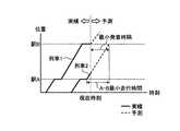
図7は、予測ダイヤの作成方法を示す図である。運行予測部11から運行管理システム20へ出力する予測結果である。現在時刻までは、列車の実績の各駅発着時刻が記録されている。運行予測部11は、前を走っている列車について、時刻的に前の方から、次の駅への到着時刻を、先行列車の実績または予測上の発時刻と、自列車の実績または予測上の発時刻と、を用いて所要時間を参照して予測する。運行予測部11は、この予測計算を繰り返して積み重ねていくことで、現在時刻以降の列車ダイヤを予測する。運行予測部11は、列車ダイヤの予測(作成)において、駅の停車時間として、駅毎に定めた一定値またはダイヤ上の停車時間等を利用する。運行予測部11は、この予測を、1日の終電まで、または現在時刻から一定時間後までの範囲で実行し、求める予測ダイヤを得る。FIG. 7 is a diagram illustrating a method for creating a prediction diagram. This is a prediction result output from the
運行予測部11において、図7に示すように(1)は列車1の駅D実績発時刻と列車2の駅C実績発時刻との差から予測、(2)は列車2の駅C実績発時刻と列車3の駅B実績発時刻との差から予測、(3)は列車3の駅B実績発時刻と列車4の駅A実績発時刻との差から予測、(4)は列車2の駅D予測発時刻と列車3の駅C予測発時刻との差から予測、(5)は列車3の駅C予測発時刻と列車4の駅B予測発時刻との差から予測したものである。 In the
運行管理システム20では、運行予測部11から予測結果(予測ダイヤ)を得ることで、運行管理システム20を扱うオペレータに対して、列車ダイヤが乱れた場合に、ダイヤ乱れがどのように波及するのか、また、どのように回復していくのか、を示すことができる。オペレータでは、短い時間で、かつ、高い精度で予測された予測ダイヤを得ることで、ダイヤ乱れに対して対策をとることが可能となる。 The
なお、運行管理システム20から運行予測部11へ列車ダイヤの情報を出力する場合に、例えば、故意にある列車の運行順番を入れ替えた情報を出力してもよい。これにより、運行予測部11は、運行管理システム20からの要望に応じた予測ダイヤを作成し、出力することができる。Note that when train schedule information is output from the
以上説明したように、本実施の形態によれば、列車走行予測装置10は、列車の運動条件に基づく列車シミュレーションを利用して、対象列車の手前の駅発時刻と先行列車の次駅発時刻との時刻差と、対象列車の次駅までの所要時間との関係を示す、駅間毎に予め作成された所要時間表を記録する所要時間DB12を備え、運行予測部11は、運行管理システム20から取得した列車ダイヤおよび列車の発着時刻の情報に基づいて、所要時間DB12に記録された所要時間表を参照し、所要時間表から対象の列車、駅における発時刻差に該当する所要時間を取得し、予測期間における各対象列車について取得した所要時間の情報に基づいて予測ダイヤを作成することとした。これにより、列車の駅単位予測において、高速かつ高い精度で予測を行うことができる。As described above, according to the present embodiment, the train
以上のように、本発明にかかる列車走行予測装置および列車走行予測方法は、列車の運行管理に有用であり、特に、列車ダイヤが乱れた場合に適している。 As described above, the train travel prediction device and the train travel prediction method according to the present invention are useful for train operation management, and are particularly suitable when the train schedule is disturbed.
10 列車走行予測装置、11 運行予測部、12 所要時間データベース(DB)、20 運行管理システム、30 列車ダイヤデータベース(DB)、40 位置検知装置。 DESCRIPTION OF
Claims (8)
Translated fromJapanese列車ダイヤおよび列車の発着実績に基づく前記発時刻差の情報を用いて、前記所要時間表を参照して前記対象列車について所要時間の情報を取得し、取得した前記所要時間の情報を用いて前記対象列車の前記次駅の駅着時刻を予測した予測ダイヤを作成する運行予測部と、
を備えることを特徴とする列車走行予測装置。And train a subsequent target train preceding train, said next stop of the target train departs the front of the station when the next station, the next station originatedthe preceding train and in front of the station onset time ofthe target train anddeparture time difference between the time, and the required time storage portion in which the showing the relationship between the time requiredfrom the current time of the target train tothe next station, recording the pre-main timetablewhere created for each between stations,
And haveuse of the information of the train schedule and trainthe calling time difference rather than based on the arrival and departureperformanceof,by referring tothe plant required time tableto get the information oftheplace attachedto the subject train requiredtime, obtained of the required time An operation prediction unit that createsa predictiondiagram that predicts a station arrival time of the next station of the target train using information ;
A train travel prediction apparatus comprising:
ことを特徴とする請求項1に記載の列車走行予測装置。The operation prediction unit sets atime obtained by adding a station stop time to thepredicted arrival time of the next station as a next station departure time, and a train schedule and the next station departure time of the target train and the next station of the preceding train. Using the information of the departure time difference with the next station departure time at the next station that is the next station, create a prediction diagram that predicts the station arrival time of the next station of the target train, and subsequent stations If there is a stop station of the target train in , continue the process of creating a prediction diagram,
The train travel prediction apparatus according to claim 1.
ことを特徴とする請求項1に記載の列車走行予測装置。The required time storage portion, asat main timetablefor each between stations, to a plurality of recording a main time tableat the case of using a different speed limit,
The train travel prediction apparatus according to claim 1.
ことを特徴とする請求項1に記載の列車走行予測装置。The required time storage portion, asat main timetablefor each between stations, to a plurality of recording a main time tableat the case of using a different driving patterns,
The train travel prediction apparatus according to claim 1.
ことを特徴とする請求項1に記載の列車走行予測装置。The required time storage portion, asat main timetablefor each between stations, to a plurality of recording a main timetableanother at vehicles of the train,
The train travel prediction apparatus according to claim 1.
を備えることを特徴とする請求項1から5のいずれか1つに記載の列車走行予測装置。Furthermore, required time calculator for calculating the required time beforeKisho main timetable,
The train travel prediction apparatus according to any one of claims 1 to 5, further comprising:
列車ダイヤおよび列車の発着実績の情報を取得する情報取得ステップと、
前記列車ダイヤおよび前記列車の発着実績に基づく前記発時刻差の情報を用いて、前記所要時間表を参照して前記対象列車について所要時間の情報を取得する所要時間取得ステップと、
取得した前記所要時間の情報を用いて前記対象列車の前記次駅の駅着時刻を予測した予測ダイヤを作成する予測ダイヤ作成ステップと、
を含むことを特徴とする列車走行予測方法。When the target train is a train that follows the preceding train and the next stop station of the station before the departure of the target train is the next station, the departure time of the station before the target train and the departure of the next station of the preceding train A train provided with a required time storage unit that records a required time table created in advance for each station, showing the relationship between the difference between the departure time and the current time of the target train to the next station A train travel prediction method in a travel prediction device,
An information acquisition step for acquiring train schedule andtrain arrival / departure information;
The train schedule andusing the information ofthe calling time differencebased on the train arrival and departureexperience, and the time required foracquiring the information oftheplace attachedto the subjecttrain main timethe required time tabletosee,
A prediction diamond creating step of creating a prediction diamondpredicted the station wearing time of the next station of the target train using the required time information obtained wastaken,
A train travel prediction method comprising:
ことを特徴とする請求項7に記載の列車走行予測方法。In theprevious Symbol prediction diamond producing step,a time obtained by adding the station stop time at the station wearing time of predicted the next station to the next station onset time, train schedules and the target train the next station onset time and the preceding train the next station Using the information of the departure time difference from the next station departure time at the next station that is the next station of the next station, a prediction diagram that predicts the station arrival time of the next station of the target train is created, If there is a stop station of the target train after the station , continue the process of creating a prediction diagram,
The train travel prediction method according to claim 7.
Applications Claiming Priority (1)
| Application Number | Priority Date | Filing Date | Title |
|---|---|---|---|
| PCT/JP2014/061181WO2015162670A1 (en) | 2014-04-21 | 2014-04-21 | Train travel prediction device and train travel prediction method |
Publications (2)
| Publication Number | Publication Date |
|---|---|
| JP5680262B1true JP5680262B1 (en) | 2015-03-04 |
| JPWO2015162670A1 JPWO2015162670A1 (en) | 2017-04-13 |
Family
ID=52684805
Family Applications (1)
| Application Number | Title | Priority Date | Filing Date |
|---|---|---|---|
| JP2014552427AActiveJP5680262B1 (en) | 2014-04-21 | 2014-04-21 | Train travel prediction apparatus and train travel prediction method |
Country Status (4)
| Country | Link |
|---|---|
| US (1) | US10407085B2 (en) |
| JP (1) | JP5680262B1 (en) |
| CN (1) | CN106232454B (en) |
| WO (1) | WO2015162670A1 (en) |
Cited By (1)
| Publication number | Priority date | Publication date | Assignee | Title |
|---|---|---|---|---|
| TWI611378B (en)* | 2016-03-03 | 2018-01-11 | Mitsubishi Electric Corp | Chaos prediction device and chaotic prediction method |
Families Citing this family (10)
| Publication number | Priority date | Publication date | Assignee | Title |
|---|---|---|---|---|
| US10279823B2 (en)* | 2016-08-08 | 2019-05-07 | General Electric Company | System for controlling or monitoring a vehicle system along a route |
| SG10201705665PA (en) | 2017-07-10 | 2019-02-27 | Nec Corp | Method and apparatus for optimizing efficiency of a transport provider |
| EP3831691A4 (en)* | 2018-07-31 | 2022-03-23 | Toshiba Digital Solutions Corporation | Train operation scheduling assist system and data structure of data about train operation scheduling |
| GB2580873A (en)* | 2018-11-02 | 2020-08-05 | Bombardier Transp Gmbh | Method and arrangement for safely operating at least one track-bound vehicle |
| CN112441085B (en)* | 2019-08-30 | 2022-03-18 | 比亚迪股份有限公司 | Vehicle operation map compilation processing method, computer equipment and storage medium |
| CN111439291B (en)* | 2020-04-23 | 2022-01-25 | 中车株洲电力机车研究所有限公司 | Late point on-line recovery method and system for rail transit system |
| EP3974286A1 (en)* | 2020-09-29 | 2022-03-30 | Siemens Mobility GmbH | Method for monitoring rail traffic and devices for executing the method |
| CN116547188B (en)* | 2020-11-04 | 2024-01-30 | 三菱电机株式会社 | Railway system, operation management device, and operation management method |
| CN112874586B (en)* | 2021-01-28 | 2022-10-21 | 浙江众合科技股份有限公司 | Urban rail transit intelligent train timetable matching method and electronic equipment |
| AU2021221626A1 (en)* | 2021-08-24 | 2023-03-16 | Technological Resources Pty. Limited | A hybrid method for controlling a railway system and an apparatus therefor |
Citations (3)
| Publication number | Priority date | Publication date | Assignee | Title |
|---|---|---|---|---|
| JP2006143088A (en)* | 2004-11-24 | 2006-06-08 | Hitachi Ltd | Operation control device |
| JP2008162400A (en)* | 2006-12-28 | 2008-07-17 | Hitachi Ltd | Railway facility environmental requirement detection system and method |
| JP2011218838A (en)* | 2010-04-05 | 2011-11-04 | Hitachi Ltd | System and device for supporting rescheduling, and method of computing train operation plan |
Family Cites Families (20)
| Publication number | Priority date | Publication date | Assignee | Title |
|---|---|---|---|---|
| JPH03127161A (en) | 1989-10-13 | 1991-05-30 | Hitachi Ltd | Coordination method of multiple consoles |
| JP2715647B2 (en) | 1990-09-28 | 1998-02-18 | 三菱電機株式会社 | Train operation prediction simulation device |
| JPH04342661A (en)* | 1991-05-20 | 1992-11-30 | Mitsubishi Electric Corp | Timetable preparation support device |
| JPH07298347A (en)* | 1994-04-25 | 1995-11-10 | Oki Electric Ind Co Ltd | Base station subordinate synchronizing method and centralized control station |
| JPH09104347A (en) | 1995-10-13 | 1997-04-22 | Hitachi Ltd | Train control system |
| JP3208054B2 (en)* | 1995-11-09 | 2001-09-10 | 三菱電機株式会社 | Train operation control support device |
| JPH09315310A (en)* | 1996-06-04 | 1997-12-09 | Toshiba Corp | Train operation management device |
| JPH10181604A (en)* | 1996-12-27 | 1998-07-07 | Mitsubishi Electric Corp | How to make a train schedule |
| JP4005541B2 (en) | 2003-02-13 | 2007-11-07 | 三菱電機株式会社 | Train travel control system and train travel control method |
| JP4471739B2 (en)* | 2004-06-08 | 2010-06-02 | 三菱電機株式会社 | Train operation control system |
| JP4734194B2 (en)* | 2006-08-07 | 2011-07-27 | 三菱電機株式会社 | Scheduling device, communication device, multi-carrier communication system, and scheduling method |
| JP4891792B2 (en)* | 2007-01-26 | 2012-03-07 | クラリオン株式会社 | Traffic information distribution method and traffic information distribution device |
| JP4796559B2 (en)* | 2007-09-21 | 2011-10-19 | 株式会社日立情報システムズ | Train delay automatic display system, train delay automatic display method, and program therefor |
| JP5292202B2 (en) | 2009-06-29 | 2013-09-18 | 株式会社日立製作所 | Train control system, ground vehicle cooperation control system |
| CN103426301B (en)* | 2012-05-18 | 2015-09-09 | 李志恒 | A kind of bus rapid transit dispatching system and method that can be accurate to second |
| CN102717819B (en)* | 2012-06-27 | 2015-07-01 | 李志恒 | Train scheduling system and method capable of being accurate to seconds for high-speed railway |
| US9108652B2 (en)* | 2012-07-09 | 2015-08-18 | General Electric Company | Method and system for timetable optimization utilizing energy consumption factors |
| HK1210852A1 (en)* | 2012-09-07 | 2016-05-06 | 姆威特App环球有限公司 | Public transportation navigator |
| US9915542B2 (en)* | 2013-12-20 | 2018-03-13 | Google Llc | Transportation system reconstruction |
| JP6276866B2 (en)* | 2014-09-22 | 2018-02-07 | 株式会社日立製作所 | Train diagram recovery system and train operation management method |
- 2014
- 2014-04-21JPJP2014552427Apatent/JP5680262B1/enactiveActive
- 2014-04-21CNCN201480078150.2Apatent/CN106232454B/enactiveActive
- 2014-04-21USUS15/305,278patent/US10407085B2/enactiveActive
- 2014-04-21WOPCT/JP2014/061181patent/WO2015162670A1/enactiveApplication Filing
Patent Citations (3)
| Publication number | Priority date | Publication date | Assignee | Title |
|---|---|---|---|---|
| JP2006143088A (en)* | 2004-11-24 | 2006-06-08 | Hitachi Ltd | Operation control device |
| JP2008162400A (en)* | 2006-12-28 | 2008-07-17 | Hitachi Ltd | Railway facility environmental requirement detection system and method |
| JP2011218838A (en)* | 2010-04-05 | 2011-11-04 | Hitachi Ltd | System and device for supporting rescheduling, and method of computing train operation plan |
Cited By (1)
| Publication number | Priority date | Publication date | Assignee | Title |
|---|---|---|---|---|
| TWI611378B (en)* | 2016-03-03 | 2018-01-11 | Mitsubishi Electric Corp | Chaos prediction device and chaotic prediction method |
Also Published As
| Publication number | Publication date |
|---|---|
| JPWO2015162670A1 (en) | 2017-04-13 |
| US10407085B2 (en) | 2019-09-10 |
| WO2015162670A1 (en) | 2015-10-29 |
| CN106232454A (en) | 2016-12-14 |
| CN106232454B (en) | 2017-12-19 |
| US20170043798A1 (en) | 2017-02-16 |
Similar Documents
| Publication | Publication Date | Title |
|---|---|---|
| JP5680262B1 (en) | Train travel prediction apparatus and train travel prediction method | |
| US12254428B2 (en) | Timetable creation apparatus, timetable creation method, and automatic vehicle control system | |
| JP5213841B2 (en) | Train schedule adjustment method and apparatus | |
| EA202091815A1 (en) | METHOD FOR PROVIDING TRAINING OF TRAINS BASED ON INTERACTION BETWEEN VEHICLES | |
| JP6307335B2 (en) | Operation management system | |
| JP6355753B2 (en) | Train operation interval control system and train operation interval control device | |
| JP2014091480A (en) | Operation arrangement device and method | |
| EP2821314A2 (en) | Train operation control system, train operation simulation device, and train operation simulation method | |
| JP6563757B2 (en) | Travel pattern creation device, automatic train operation system with travel pattern creation device and automatic train operation device, and drive support system with travel pattern creation device and operation support device | |
| JP2010221839A (en) | Train operation prediction device | |
| JP2002249049A (en) | Traffic control device | |
| JP2014034358A (en) | Program, and train operation simulator | |
| JP6736392B2 (en) | Travel pattern creation device and travel pattern creation method | |
| JP6637720B2 (en) | Operation management device | |
| RU2018139294A (en) | METHOD OF TRANSPORT MOVEMENT MANAGEMENT AND TRANSPORT MOTION MANAGEMENT SYSTEM | |
| Sánchez-Martínez et al. | Event-driven holding control for high-frequency transit | |
| JP5635300B2 (en) | Train control system | |
| JP7232673B2 (en) | TRAIN OPERATION CONTROL DEVICE AND TRAIN OPERATION CONTROL METHOD | |
| JP6632362B2 (en) | Operation management device | |
| JP6530985B2 (en) | Automatic train driver | |
| EP4056451A1 (en) | Method and system for regulating guided vehicles headways | |
| JP6139372B2 (en) | Operation plan creation device | |
| HK1230143B (en) | Train travel prediction device and train travel prediction method | |
| JP6533381B2 (en) | Schedule management device | |
| WATANABE et al. | 1F13 A Mesoscopic Train Traffic Simulation Algorithm considering Running times of Block Sections (Operation management) |
Legal Events
| Date | Code | Title | Description |
|---|---|---|---|
| TRDD | Decision of grant or rejection written | ||
| A975 | Report on accelerated examination | Free format text:JAPANESE INTERMEDIATE CODE: A971005 Effective date:20141202 | |
| A01 | Written decision to grant a patent or to grant a registration (utility model) | Free format text:JAPANESE INTERMEDIATE CODE: A01 Effective date:20141209 | |
| A61 | First payment of annual fees (during grant procedure) | Free format text:JAPANESE INTERMEDIATE CODE: A61 Effective date:20150106 | |
| R150 | Certificate of patent or registration of utility model | Ref document number:5680262 Country of ref document:JP Free format text:JAPANESE INTERMEDIATE CODE: R150 | |
| R250 | Receipt of annual fees | Free format text:JAPANESE INTERMEDIATE CODE: R250 | |
| R250 | Receipt of annual fees | Free format text:JAPANESE INTERMEDIATE CODE: R250 | |
| R250 | Receipt of annual fees | Free format text:JAPANESE INTERMEDIATE CODE: R250 | |
| R250 | Receipt of annual fees | Free format text:JAPANESE INTERMEDIATE CODE: R250 | |
| R250 | Receipt of annual fees | Free format text:JAPANESE INTERMEDIATE CODE: R250 | |
| R250 | Receipt of annual fees | Free format text:JAPANESE INTERMEDIATE CODE: R250 | |
| R250 | Receipt of annual fees | Free format text:JAPANESE INTERMEDIATE CODE: R250 | |
| R250 | Receipt of annual fees | Free format text:JAPANESE INTERMEDIATE CODE: R250 |