JP5678214B2 - Magnetic mounting unit - Google Patents
Magnetic mounting unitDownload PDFInfo
- Publication number
- JP5678214B2 JP5678214B2JP2013551395AJP2013551395AJP5678214B2JP 5678214 B2JP5678214 B2JP 5678214B2JP 2013551395 AJP2013551395 AJP 2013551395AJP 2013551395 AJP2013551395 AJP 2013551395AJP 5678214 B2JP5678214 B2JP 5678214B2
- Authority
- JP
- Japan
- Prior art keywords
- electronic device
- magnetic
- attachment
- magnetic attachment
- tablet
- Prior art date
- Legal status (The legal status is an assumption and is not a legal conclusion. Google has not performed a legal analysis and makes no representation as to the accuracy of the status listed.)
- Expired - Fee Related
Links
Images


Classifications
- G—PHYSICS
- G06—COMPUTING OR CALCULATING; COUNTING
- G06F—ELECTRIC DIGITAL DATA PROCESSING
- G06F1/00—Details not covered by groups G06F3/00 - G06F13/00 and G06F21/00
- G06F1/16—Constructional details or arrangements
- G06F1/1613—Constructional details or arrangements for portable computers
- G06F1/1632—External expansion units, e.g. docking stations
- A—HUMAN NECESSITIES
- A45—HAND OR TRAVELLING ARTICLES
- A45C—PURSES; LUGGAGE; HAND CARRIED BAGS
- A45C11/00—Receptacles for purposes not provided for in groups A45C1/00-A45C9/00
- A—HUMAN NECESSITIES
- A45—HAND OR TRAVELLING ARTICLES
- A45C—PURSES; LUGGAGE; HAND CARRIED BAGS
- A45C11/00—Receptacles for purposes not provided for in groups A45C1/00-A45C9/00
- A45C11/003—Receptacles for purposes not provided for in groups A45C1/00-A45C9/00 for storing portable computing devices, e.g. laptops, tablets or calculators
- A—HUMAN NECESSITIES
- A45—HAND OR TRAVELLING ARTICLES
- A45C—PURSES; LUGGAGE; HAND CARRIED BAGS
- A45C13/00—Details; Accessories
- A45C13/002—Protective covers
- A—HUMAN NECESSITIES
- A45—HAND OR TRAVELLING ARTICLES
- A45C—PURSES; LUGGAGE; HAND CARRIED BAGS
- A45C15/00—Purses, bags, luggage or other receptacles covered by groups A45C1/00 - A45C11/00, combined with other objects or articles
- A—HUMAN NECESSITIES
- A63—SPORTS; GAMES; AMUSEMENTS
- A63B—APPARATUS FOR PHYSICAL TRAINING, GYMNASTICS, SWIMMING, CLIMBING, OR FENCING; BALL GAMES; TRAINING EQUIPMENT
- A63B71/00—Games or sports accessories not covered in groups A63B1/00 - A63B69/00
- A63B71/06—Indicating or scoring devices for games or players, or for other sports activities
- A63B71/0619—Displays, user interfaces and indicating devices, specially adapted for sport equipment, e.g. display mounted on treadmills
- A63B71/0622—Visual, audio or audio-visual systems for entertaining, instructing or motivating the user
- B—PERFORMING OPERATIONS; TRANSPORTING
- B60—VEHICLES IN GENERAL
- B60R—VEHICLES, VEHICLE FITTINGS, OR VEHICLE PARTS, NOT OTHERWISE PROVIDED FOR
- B60R11/00—Arrangements for holding or mounting articles, not otherwise provided for
- B60R11/02—Arrangements for holding or mounting articles, not otherwise provided for for radio sets, television sets, telephones, or the like; Arrangement of controls thereof
- B60R11/0252—Arrangements for holding or mounting articles, not otherwise provided for for radio sets, television sets, telephones, or the like; Arrangement of controls thereof for personal computers, e.g. laptops, notebooks
- G—PHYSICS
- G06—COMPUTING OR CALCULATING; COUNTING
- G06F—ELECTRIC DIGITAL DATA PROCESSING
- G06F1/00—Details not covered by groups G06F3/00 - G06F13/00 and G06F21/00
- G06F1/16—Constructional details or arrangements
- G06F1/1613—Constructional details or arrangements for portable computers
- G06F1/1615—Constructional details or arrangements for portable computers with several enclosures having relative motions, each enclosure supporting at least one I/O or computing function
- G06F1/1616—Constructional details or arrangements for portable computers with several enclosures having relative motions, each enclosure supporting at least one I/O or computing function with folding flat displays, e.g. laptop computers or notebooks having a clamshell configuration, with body parts pivoting to an open position around an axis parallel to the plane they define in closed position
- G—PHYSICS
- G06—COMPUTING OR CALCULATING; COUNTING
- G06F—ELECTRIC DIGITAL DATA PROCESSING
- G06F1/00—Details not covered by groups G06F3/00 - G06F13/00 and G06F21/00
- G06F1/16—Constructional details or arrangements
- G06F1/1613—Constructional details or arrangements for portable computers
- G06F1/1626—Constructional details or arrangements for portable computers with a single-body enclosure integrating a flat display, e.g. Personal Digital Assistants [PDAs]
- G—PHYSICS
- G06—COMPUTING OR CALCULATING; COUNTING
- G06F—ELECTRIC DIGITAL DATA PROCESSING
- G06F1/00—Details not covered by groups G06F3/00 - G06F13/00 and G06F21/00
- G06F1/16—Constructional details or arrangements
- G06F1/1613—Constructional details or arrangements for portable computers
- G06F1/1633—Constructional details or arrangements of portable computers not specific to the type of enclosures covered by groups G06F1/1615 - G06F1/1626
- G06F1/1637—Details related to the display arrangement, including those related to the mounting of the display in the housing
- G06F1/1643—Details related to the display arrangement, including those related to the mounting of the display in the housing the display being associated to a digitizer, e.g. laptops that can be used as penpads
- G—PHYSICS
- G06—COMPUTING OR CALCULATING; COUNTING
- G06F—ELECTRIC DIGITAL DATA PROCESSING
- G06F1/00—Details not covered by groups G06F3/00 - G06F13/00 and G06F21/00
- G06F1/16—Constructional details or arrangements
- G06F1/1613—Constructional details or arrangements for portable computers
- G06F1/1633—Constructional details or arrangements of portable computers not specific to the type of enclosures covered by groups G06F1/1615 - G06F1/1626
- G06F1/1637—Details related to the display arrangement, including those related to the mounting of the display in the housing
- G06F1/1647—Details related to the display arrangement, including those related to the mounting of the display in the housing including at least an additional display
- G—PHYSICS
- G06—COMPUTING OR CALCULATING; COUNTING
- G06F—ELECTRIC DIGITAL DATA PROCESSING
- G06F1/00—Details not covered by groups G06F3/00 - G06F13/00 and G06F21/00
- G06F1/16—Constructional details or arrangements
- G06F1/1613—Constructional details or arrangements for portable computers
- G06F1/1633—Constructional details or arrangements of portable computers not specific to the type of enclosures covered by groups G06F1/1615 - G06F1/1626
- G06F1/1637—Details related to the display arrangement, including those related to the mounting of the display in the housing
- G06F1/1652—Details related to the display arrangement, including those related to the mounting of the display in the housing the display being flexible, e.g. mimicking a sheet of paper, or rollable
- G—PHYSICS
- G06—COMPUTING OR CALCULATING; COUNTING
- G06F—ELECTRIC DIGITAL DATA PROCESSING
- G06F1/00—Details not covered by groups G06F3/00 - G06F13/00 and G06F21/00
- G06F1/16—Constructional details or arrangements
- G06F1/1613—Constructional details or arrangements for portable computers
- G06F1/1633—Constructional details or arrangements of portable computers not specific to the type of enclosures covered by groups G06F1/1615 - G06F1/1626
- G06F1/1637—Details related to the display arrangement, including those related to the mounting of the display in the housing
- G06F1/1654—Details related to the display arrangement, including those related to the mounting of the display in the housing the display being detachable, e.g. for remote use
- G—PHYSICS
- G06—COMPUTING OR CALCULATING; COUNTING
- G06F—ELECTRIC DIGITAL DATA PROCESSING
- G06F1/00—Details not covered by groups G06F3/00 - G06F13/00 and G06F21/00
- G06F1/16—Constructional details or arrangements
- G06F1/1613—Constructional details or arrangements for portable computers
- G06F1/1633—Constructional details or arrangements of portable computers not specific to the type of enclosures covered by groups G06F1/1615 - G06F1/1626
- G06F1/1656—Details related to functional adaptations of the enclosure, e.g. to provide protection against EMI, shock, water, or to host detachable peripherals like a mouse or removable expansions units like PCMCIA cards, or to provide access to internal components for maintenance or to removable storage supports like CDs or DVDs, or to mechanically mount accessories
- G—PHYSICS
- G06—COMPUTING OR CALCULATING; COUNTING
- G06F—ELECTRIC DIGITAL DATA PROCESSING
- G06F1/00—Details not covered by groups G06F3/00 - G06F13/00 and G06F21/00
- G06F1/16—Constructional details or arrangements
- G06F1/1613—Constructional details or arrangements for portable computers
- G06F1/1633—Constructional details or arrangements of portable computers not specific to the type of enclosures covered by groups G06F1/1615 - G06F1/1626
- G06F1/1662—Details related to the integrated keyboard
- G06F1/1673—Arrangements for projecting a virtual keyboard
- G—PHYSICS
- G06—COMPUTING OR CALCULATING; COUNTING
- G06F—ELECTRIC DIGITAL DATA PROCESSING
- G06F1/00—Details not covered by groups G06F3/00 - G06F13/00 and G06F21/00
- G06F1/16—Constructional details or arrangements
- G06F1/1613—Constructional details or arrangements for portable computers
- G06F1/1633—Constructional details or arrangements of portable computers not specific to the type of enclosures covered by groups G06F1/1615 - G06F1/1626
- G06F1/1675—Miscellaneous details related to the relative movement between the different enclosures or enclosure parts
- G06F1/1681—Details related solely to hinges
- G—PHYSICS
- G06—COMPUTING OR CALCULATING; COUNTING
- G06F—ELECTRIC DIGITAL DATA PROCESSING
- G06F3/00—Input arrangements for transferring data to be processed into a form capable of being handled by the computer; Output arrangements for transferring data from processing unit to output unit, e.g. interface arrangements
- G06F3/01—Input arrangements or combined input and output arrangements for interaction between user and computer
- G06F3/02—Input arrangements using manually operated switches, e.g. using keyboards or dials
- G06F3/0202—Constructional details or processes of manufacture of the input device
- G—PHYSICS
- G06—COMPUTING OR CALCULATING; COUNTING
- G06F—ELECTRIC DIGITAL DATA PROCESSING
- G06F3/00—Input arrangements for transferring data to be processed into a form capable of being handled by the computer; Output arrangements for transferring data from processing unit to output unit, e.g. interface arrangements
- G06F3/01—Input arrangements or combined input and output arrangements for interaction between user and computer
- G06F3/048—Interaction techniques based on graphical user interfaces [GUI]
- G06F3/0481—Interaction techniques based on graphical user interfaces [GUI] based on specific properties of the displayed interaction object or a metaphor-based environment, e.g. interaction with desktop elements like windows or icons, or assisted by a cursor's changing behaviour or appearance
- G06F3/0482—Interaction with lists of selectable items, e.g. menus
- G—PHYSICS
- G06—COMPUTING OR CALCULATING; COUNTING
- G06F—ELECTRIC DIGITAL DATA PROCESSING
- G06F3/00—Input arrangements for transferring data to be processed into a form capable of being handled by the computer; Output arrangements for transferring data from processing unit to output unit, e.g. interface arrangements
- G06F3/01—Input arrangements or combined input and output arrangements for interaction between user and computer
- G06F3/048—Interaction techniques based on graphical user interfaces [GUI]
- G06F3/0487—Interaction techniques based on graphical user interfaces [GUI] using specific features provided by the input device, e.g. functions controlled by the rotation of a mouse with dual sensing arrangements, or of the nature of the input device, e.g. tap gestures based on pressure sensed by a digitiser
- G06F3/0488—Interaction techniques based on graphical user interfaces [GUI] using specific features provided by the input device, e.g. functions controlled by the rotation of a mouse with dual sensing arrangements, or of the nature of the input device, e.g. tap gestures based on pressure sensed by a digitiser using a touch-screen or digitiser, e.g. input of commands through traced gestures
- G06F3/04883—Interaction techniques based on graphical user interfaces [GUI] using specific features provided by the input device, e.g. functions controlled by the rotation of a mouse with dual sensing arrangements, or of the nature of the input device, e.g. tap gestures based on pressure sensed by a digitiser using a touch-screen or digitiser, e.g. input of commands through traced gestures for inputting data by handwriting, e.g. gesture or text
- G—PHYSICS
- G06—COMPUTING OR CALCULATING; COUNTING
- G06F—ELECTRIC DIGITAL DATA PROCESSING
- G06F3/00—Input arrangements for transferring data to be processed into a form capable of being handled by the computer; Output arrangements for transferring data from processing unit to output unit, e.g. interface arrangements
- G06F3/14—Digital output to display device ; Cooperation and interconnection of the display device with other functional units
- G06F3/1423—Digital output to display device ; Cooperation and interconnection of the display device with other functional units controlling a plurality of local displays, e.g. CRT and flat panel display
- G06F3/1446—Digital output to display device ; Cooperation and interconnection of the display device with other functional units controlling a plurality of local displays, e.g. CRT and flat panel display display composed of modules, e.g. video walls
- H—ELECTRICITY
- H04—ELECTRIC COMMUNICATION TECHNIQUE
- H04B—TRANSMISSION
- H04B1/00—Details of transmission systems, not covered by a single one of groups H04B3/00 - H04B13/00; Details of transmission systems not characterised by the medium used for transmission
- H04B1/38—Transceivers, i.e. devices in which transmitter and receiver form a structural unit and in which at least one part is used for functions of transmitting and receiving
- H04B1/3822—Transceivers, i.e. devices in which transmitter and receiver form a structural unit and in which at least one part is used for functions of transmitting and receiving specially adapted for use in vehicles
- A—HUMAN NECESSITIES
- A45—HAND OR TRAVELLING ARTICLES
- A45C—PURSES; LUGGAGE; HAND CARRIED BAGS
- A45C2200/00—Details not otherwise provided for in A45C
- A45C2200/15—Articles convertible into a stand, e.g. for displaying purposes
- A—HUMAN NECESSITIES
- A63—SPORTS; GAMES; AMUSEMENTS
- A63B—APPARATUS FOR PHYSICAL TRAINING, GYMNASTICS, SWIMMING, CLIMBING, OR FENCING; BALL GAMES; TRAINING EQUIPMENT
- A63B71/00—Games or sports accessories not covered in groups A63B1/00 - A63B69/00
- A63B71/06—Indicating or scoring devices for games or players, or for other sports activities
- A63B71/0619—Displays, user interfaces and indicating devices, specially adapted for sport equipment, e.g. display mounted on treadmills
- A63B2071/0658—Position or arrangement of display
- B—PERFORMING OPERATIONS; TRANSPORTING
- B60—VEHICLES IN GENERAL
- B60R—VEHICLES, VEHICLE FITTINGS, OR VEHICLE PARTS, NOT OTHERWISE PROVIDED FOR
- B60R11/00—Arrangements for holding or mounting articles, not otherwise provided for
- B60R2011/0001—Arrangements for holding or mounting articles, not otherwise provided for characterised by position
- B60R2011/0003—Arrangements for holding or mounting articles, not otherwise provided for characterised by position inside the vehicle
- B60R2011/0005—Dashboard
- B—PERFORMING OPERATIONS; TRANSPORTING
- B60—VEHICLES IN GENERAL
- B60R—VEHICLES, VEHICLE FITTINGS, OR VEHICLE PARTS, NOT OTHERWISE PROVIDED FOR
- B60R11/00—Arrangements for holding or mounting articles, not otherwise provided for
- B60R2011/0001—Arrangements for holding or mounting articles, not otherwise provided for characterised by position
- B60R2011/0003—Arrangements for holding or mounting articles, not otherwise provided for characterised by position inside the vehicle
- B60R2011/0012—Seats or parts thereof
- B60R2011/0017—Head-rests
- B—PERFORMING OPERATIONS; TRANSPORTING
- B60—VEHICLES IN GENERAL
- B60R—VEHICLES, VEHICLE FITTINGS, OR VEHICLE PARTS, NOT OTHERWISE PROVIDED FOR
- B60R11/00—Arrangements for holding or mounting articles, not otherwise provided for
- B60R2011/0042—Arrangements for holding or mounting articles, not otherwise provided for characterised by mounting means
- B60R2011/0049—Arrangements for holding or mounting articles, not otherwise provided for characterised by mounting means for non integrated articles
- B60R2011/005—Connection with the vehicle part
- B60R2011/0057—Connection with the vehicle part using magnetic means
- G—PHYSICS
- G06—COMPUTING OR CALCULATING; COUNTING
- G06F—ELECTRIC DIGITAL DATA PROCESSING
- G06F2200/00—Indexing scheme relating to G06F1/04 - G06F1/32
- G06F2200/16—Indexing scheme relating to G06F1/16 - G06F1/18
- G06F2200/163—Indexing scheme relating to constructional details of the computer
- G06F2200/1631—Panel PC, e.g. single housing hosting PC and display panel
Landscapes
- Engineering & Computer Science (AREA)
- Theoretical Computer Science (AREA)
- Computer Hardware Design (AREA)
- General Engineering & Computer Science (AREA)
- Physics & Mathematics (AREA)
- Human Computer Interaction (AREA)
- General Physics & Mathematics (AREA)
- Multimedia (AREA)
- Signal Processing (AREA)
- Mathematical Physics (AREA)
- Health & Medical Sciences (AREA)
- General Health & Medical Sciences (AREA)
- Physical Education & Sports Medicine (AREA)
- Computer Networks & Wireless Communication (AREA)
- Mechanical Engineering (AREA)
- Casings For Electric Apparatus (AREA)
- Telephone Set Structure (AREA)
- User Interface Of Digital Computer (AREA)
- Devices For Indicating Variable Information By Combining Individual Elements (AREA)
- Position Input By Displaying (AREA)
- Control Of Indicators Other Than Cathode Ray Tubes (AREA)
- Digital Computer Display Output (AREA)
- Input From Keyboards Or The Like (AREA)
- Adornments (AREA)
- Controls And Circuits For Display Device (AREA)
- Supports Or Holders For Household Use (AREA)
- Fire Alarms (AREA)
- Measuring And Recording Apparatus For Diagnosis (AREA)
Description
Translated fromJapanese記載される実施形態は一般にポータブル電子デバイスに関する。より具体的に、本実施形態はポータブル電子デバイスに適した解放可能な取りつけ技術を記載する。 The described embodiments generally relate to portable electronic devices. More specifically, this embodiment describes a releasable mounting technique suitable for portable electronic devices.
ポータブルコンピューティングにおける最近の進歩は、カリフォルニア州クパチーノのアップルインクにより製造されるiPad(登録商標)タブレットのラインに沿ったハンドヘルド電子デバイス及びコンピューティングプラットフォームの導入を含む。これらのハンドヘルドコンピューティングデバイスは、電子デバイスの実質的な部分が、アクセサリデバイスを取り付けるために用いられうる取り付け機構のために利用可能なわずかなスペースを残して、視覚コンテンツを提示するために用いられるディスプレイの形態をとるように構成されうる。 Recent advances in portable computing include the introduction of handheld electronic devices and computing platforms along the line of iPad® tablets manufactured by Apple Inc. of Cupertino, California. These handheld computing devices are used for presenting visual content, leaving a substantial portion of the electronic device available for attachment mechanisms that can be used to attach accessory devices. It can be configured to take the form of a display.
従来の取り付け技術は一般に、アクセサリデバイスの対応する取り付け特徴部(feature)に係合するための電子デバイスの少なくとも外部からアクセス可能な取り付け特徴部を典型的に必要とする機械的留め具に依存する。外部の取り付け特徴部の存在は、ハンドヘルドコンピューティングデバイスの全体的な見た目を損なうだけでなく、不要な重さ及び複雑さを付加し、さらにはハンドヘルドコンピューティングデバイスの見かけを損ないうる。 Conventional attachment techniques generally rely on mechanical fasteners that typically require attachment features accessible at least externally of the electronic device to engage corresponding attachment features of the accessory device. . The presence of external mounting features not only detracts from the overall look of the handheld computing device, but also adds unnecessary weight and complexity, and can even detract from the appearance of the handheld computing device.
従って、少なくとも2つの物体を共に解放可能に取り付けるための機構が必要となる。 Therefore, a mechanism for releasably attaching both at least two objects is required.
本明細書は、磁気取り付けを用いた共同システムを形成するためのシステム、方法及び装置に関する様々な実施形態を記載する。 This specification describes various embodiments of systems, methods and apparatus for forming a collaborative system using magnetic attachment.
共同システムを形成するために第1磁気取り付けシステムを有する第1物体と第2磁気取り付けシステムを有する第2物体とを共に磁気で取り付けるための磁気取り付けユニットが記載される。磁気取り付けユニットは、第1磁気システムを作動させるための第1差動力と第2磁気システムを作動させるための第2差動力とを与えるように構成された磁気取り付けシステムを少なくとも含む。作動した第1磁気システムと作動した第2磁気システムとは、共同する磁気システムを形成するために第1物体と第2物体とを共に解放可能に固定するように磁気取り付けシステムと共同する。 A magnetic attachment unit is described for magnetically attaching together a first object having a first magnetic attachment system and a second object having a second magnetic attachment system to form a collaborative system. The magnetic mounting unit includes at least a magnetic mounting system configured to provide a first differential force for operating the first magnetic system and a second differential force for operating the second magnetic system. The actuated first magnetic system and the actuated second magnetic system cooperate with the magnetic attachment system to releasably secure the first and second objects together to form a cooperating magnetic system.
関連する磁気取り付け特徴部をそれぞれが有する少なくとも個別の第1電子デバイスと個別の第2電子デバイスとを共に磁気で取り付けるための磁気取り付けユニットであって、磁気で取り付けられた電子デバイスは、共同電子システムを形成するように磁気で取り付けられた場合に互いに通信する。前記磁気取り付けユニットは、第1側と、前記第1側とは反対の第2側とを有する本体と、前記本体の第1側において、前記第1電子デバイスの対応する磁気取り付け特徴部を有効化するための第1有効化力を与えるように構成された第1磁石を少なくとも有する第1磁気取り付けシステムと、前記本体の第2側において、前記第2電子デバイスの対応する磁気取り付け特徴部を有効化するための第2有効化力を与えるように構成された第2磁石を少なくとも有する第2磁気取り付けシステムとを備え、前記有効化した第1磁気システム及び前記有効化した第2磁気システムと前記磁気取り付けユニットの対応する磁石との間に生成された磁気取り付け力は、前記個別の第1電子デバイスと前記個別の第2電子デバイスとが共同する電子デバイスとして共に動作可能になるようにする。 A magnetic attachment unit for magnetically attaching together at least an individual first electronic device and an individual second electronic device each having an associated magnetic attachment feature, the magnetically attached electronic device comprising: Communicate with each other when magnetically attached to form a system. The magnetic attachment unit has a main body having a first side and a second side opposite to the first side, and a corresponding magnetic attachment feature of the first electronic device is effective on the first side of the main body. A first magnetic attachment system having at least a first magnet configured to provide a first activation force to enable and a corresponding magnetic attachment feature of the second electronic device on the second side of the body. A second magnetic attachment system having at least a second magnet configured to provide a second activation force for activation, the activated first magnetic system and the activated second magnetic system; The magnetic attachment force generated between the corresponding magnets of the magnetic attachment unit is an electronic device that the individual first electronic device and the individual second electronic device cooperate. So that both become operational as scan.
ホストユニットに取り外し可能に接続されたヒンジアセンブリと、前記ホストユニットに従うサイズ及び形状を有するヒンジアセンブリに旋回可能に取り付けられたカバーアセンブリとを備えるカバーアセンブリが記載される。前記カバーアセンブリは、第1旋回軸において前記ヒンジ部に旋回可能に取り付けられたカバー部と、前記第1旋回軸とは異なる第2旋回軸において前記ヒンジ部に旋回可能に取り付けられた前記カバー部から分離したフラップ部とを備え、前記フラップ部に対して傾斜した角度で前記ホストデバイスを支持する支持構造体を前記カバーが形成するように前記カバー部及び前記フラップ部がそれぞれの旋回中心の周りを回転する。 A cover assembly is described comprising a hinge assembly removably connected to a host unit and a cover assembly pivotally attached to the hinge assembly having a size and shape according to the host unit. The cover assembly includes a cover part pivotally attached to the hinge part on a first pivot axis, and the cover part pivotally attached to the hinge part on a second pivot axis different from the first pivot axis. The cover portion and the flap portion around their respective pivot centers so that the cover forms a support structure that supports the host device at an inclined angle with respect to the flap portion. Rotate.
ドッキングステーションはホストデバイスを支持するように構成されたベース部を少なくとも備え、前記ベース部は、前記ホストデバイスと前記ベース部とを取り外し可能に固定するように構成された取り付けユニットと、ユーザ入力イベントを受けるように構成されたユーザ入力部と、前記ホストデバイスと前記ベース部の前記ユーザ入力部との間に通信パスを与えるように構成された通信ポートとを備え、前記ユーザ入力部における前記ユーザ入力イベントに関連する情報は、前記通信ポートによって与えられる前記通信パスを用いて前記ホストデバイスに渡される。 The docking station includes at least a base portion configured to support a host device, the base portion configured to removably secure the host device and the base portion, and a user input event. A user input unit configured to receive the communication, and a communication port configured to provide a communication path between the host device and the user input unit of the base unit, the user in the user input unit Information related to the input event is passed to the host device using the communication path provided by the communication port.
本発明の他の側面及び利点は、記載される実施形態の原理を例示の方法で説明する添付の図面と合わせて解釈される以下の詳細な説明から明らかになるだろう。 Other aspects and advantages of the present invention will become apparent from the following detailed description, taken in conjunction with the accompanying drawings, illustrating by way of example the principles of the described embodiments.
本発明は添付の図面と合わせて以下の詳細な説明から容易に理解され、図面では同様の参照符号は同様の構成要素を表す。 The present invention will be readily understood by the following detailed description in conjunction with the accompanying drawings, and like reference numerals designate like structural elements.
添付の図面に説明される代表的な実施形態が以下に詳細に参照される。以下の記載は複数の実施形態を1つの好適な実施形態に限定する意図がないことが理解されるべきである。反対に、添付の特許請求の範囲で規定されるように、記載される実施形態の精神及び範囲内に含まれうる変形、修正及び均等物をカバーすることが意図される。 Reference will now be made in detail to the exemplary embodiments illustrated in the accompanying drawings. It should be understood that the following description is not intended to limit the embodiments to one preferred embodiment. On the contrary, it is intended to cover variations, modifications, and equivalents that may be included within the spirit and scope of the described embodiments as defined in the appended claims.
以下の記載は一般に、少なくとも2つの適切に構成された物体を共に取り付けるために用いられうる機構に関する。1つの実施形態では、これは従来の留め具を用いることなく実現されうる。物体のそれぞれは、適切な特性を有する磁界を提供するように構成された取り付け特徴部を含みうる。取り付け特徴部が互いに近くにもたらされた場合に、磁界はそれぞれの特性に基づいて共同して相互作用でき、結果として物体が所望の反復可能な方法で互いに磁気で取り付けられうる。例えば、磁界の相互作用の共同特性に少なくとも部分的に起因して、物体は外部からの介入なしに事前に決められた位置及び相対的方向に互いに取り付けうる。例えば、共同磁気相互作用の結果として、物体は所望の方向に自己アライメント及び自己センタリングされうる。 The following description relates generally to a mechanism that can be used to attach at least two properly configured objects together. In one embodiment, this can be achieved without using conventional fasteners. Each of the objects may include an attachment feature configured to provide a magnetic field with appropriate characteristics. When the attachment features are brought close to each other, the magnetic fields can interact jointly based on their respective properties, so that the objects can be magnetically attached to each other in the desired repeatable manner. For example, objects can be attached to each other in a predetermined position and relative orientation without external intervention, due at least in part to the joint properties of magnetic field interactions. For example, as a result of the joint magnetic interaction, the object can be self-aligned and self-centered in the desired direction.
正味磁気引力全体に打ち勝つのに十分な強さの解放力が印加されるまで物体は磁気で取り付けられた状態に留まりうる。しかしながら、一部の場合に、物体を(ジッパのラインに沿って)連続的に取り外すことが望ましく、この場合に、解放力は、一度に磁気素子の1つのペアの正味磁気引力に打ち勝つのに十分な強さだけが必要になる。物体を取り付けるために機械式留め具のようなコネクタは必要とならない。さらに、磁気取り付け特徴部間の磁気相互作用への不要な干渉を避けるために、磁気取り付け特徴部の近くにある物体の少なくとも一部は、プラスチックや、アルミニウム又は非磁気ステンレススチールのような非鉄金属のような磁気的に不活性な物質で形成されうる。 The object can remain magnetically attached until a release force that is strong enough to overcome the overall net magnetic attraction is applied. However, in some cases it is desirable to remove the object continuously (along the zipper line), in which case the release force will overcome the net magnetic attraction of one pair of magnetic elements at a time. Only enough strength is needed. A connector such as a mechanical fastener is not required to attach the object. In addition, to avoid unnecessary interference with the magnetic interaction between the magnetic attachment features, at least some of the objects near the magnetic attachment features are made of plastic, non-ferrous metals such as aluminum or non-magnetic stainless steel Or a magnetically inactive material such as
物体は多くの形態をとってもよく、多くの機能を実行しうる。互いに磁気で取り付けられた場合に、物体は共同するシステムを形成するように互いに通信し、相互作用しうる。共同するシステムは動作を実行し、別個の物体によっては個別に提供できない機能を提供する。別の実施形態では、少なくとも1つのデバイスは、アクセサリデバイスとして用いられうる。アクセサリデバイスは少なくとも1つの電子デバイスに磁気で取り付けられうる。アクセサリデバイスは、電子デバイス(群)の操作性を向上するために用いられうるサービス及び機能を提供できる。例えば、アクセサリデバイスは、電子デバイスに磁気で取り付けられ、電子デバイスを囲みうる保護ケースの形態を取りうる。保護ケースは電子デバイスの(ディスプレイのような)所定の側面への保護だけでなく、電子デバイス全体への保護を提供できる。保護ケースと電子デバイスとを磁気で取り付けるために用いられる磁気取り付け機構は、保護ケースが特定の方向においてのみ電子デバイスに取り付くことができることを保証できる。さらに、磁気取り付け機構はまた、保護ケースと電子デバイスとの適切なアライメント及び位置決めを保証できる。 An object may take many forms and perform many functions. When magnetically attached to each other, objects can communicate and interact with each other to form a collaborative system. The collaborative system performs operations and provides functions that cannot be provided individually by separate objects. In another embodiment, at least one device can be used as an accessory device. The accessory device can be magnetically attached to the at least one electronic device. The accessory device can provide services and functions that can be used to improve the operability of the electronic device (s). For example, the accessory device can be in the form of a protective case that can be magnetically attached to the electronic device and surround the electronic device. The protective case can provide protection for the entire electronic device as well as protection for certain aspects of the electronic device (such as a display). The magnetic attachment mechanism used to magnetically attach the protective case and the electronic device can ensure that the protective case can be attached to the electronic device only in a specific direction. Furthermore, the magnetic attachment mechanism can also ensure proper alignment and positioning of the protective case and the electronic device.
1つの実施形態では、第1物体が第2物体への支持機構を提供するように構成されうるように、第1物体と第2物体とが互いに磁気で取り付けられうる。支持機構は本質的に機械的でありうる。例えば、第1物体は、テーブルのような作業面に第2物体を支持するために用いられうるスタンドの形態を取りうる。1つの実施形態では、スタンドは、複数の角度及び方向で第2物体を提示するように構成された連接型スタンドの形態を取りうる。 In one embodiment, the first object and the second object can be magnetically attached to each other so that the first object can be configured to provide a support mechanism for the second object. The support mechanism can be mechanical in nature. For example, the first object can take the form of a stand that can be used to support the second object on a work surface such as a table. In one embodiment, the stand may take the form of an articulating stand configured to present the second object at a plurality of angles and directions.
1つの実施形態では、第1物体は、特定の方法で第2物体に磁気で取り付くように構成されたドックの形態を取りうる。第2物体が電子デバイスである場合にドックは本質的に電子機器でありうる。ドックは、外部電源から電子デバイスへ電力を提供できる電気接点を提供できる。電気接点はまた、電子デバイスへ情報が提供されうるだけでなく、電子デバイスから情報が提供されうる機構を提供できる。例えば、ドックは、電子デバイスから受信したオーディオ信号に基づいて音を広めるように構成されたスピーカのようなオーディオ出力デバイスを含みうる。 In one embodiment, the first object may take the form of a dock configured to magnetically attach to the second object in a particular manner. The dock can be essentially an electronic device when the second object is an electronic device. The dock can provide electrical contacts that can provide power to the electronic device from an external power source. Electrical contacts can also provide a mechanism by which information can be provided to the electronic device as well as information from the electronic device. For example, the dock may include an audio output device such as a speaker configured to spread sound based on an audio signal received from the electronic device.
1つの実施形態では、第1物体は吊り下げ装置の形態を取りうる。このようなものとして、第1物体は第2物体を吊り下げるために用いられてもよく、その後第2物体は、写真、美術品等のような視覚的な静止画像のような視覚コンテンツを提示するためのディスプレイとして用いられうる。支持機構はまた、第2物体を便利に掴む又は保持するための持ち手として用いられうる。この構成は、第2物体が画像(静止画又はビジュアル)、(電子書籍におけるような)テキストのような視覚コンテンツを提示できる場合や、静止又はビジュアルカメラのような画像撮像デバイスとして第2物体が用いられ、三脚又は持ち手のような支持体として第1物体が機能するように構成されうる場合に特に有用でありうる。持ち手は固定式であってもよいし、可動式であってもよい。1つの実施形態では、吊り下げ装置は、フック、吸着カップ、又は他の任意の適切な吊り下げデバイスの形態を取りうる。例えば、吊り下げ装置は電子デバイスをホワイトボードに固定するために用いられうる。1つの実施形態では、フックの形態の吊り下げ装置は電子デバイスを自動車、飛行機又は電車のシートクッションに固定するために用いられうる。このようにして、電子デバイスは、ディスプレイスクリーンを見るための位置に座る人に視覚コンテンツを提供できる。 In one embodiment, the first object may take the form of a suspension device. As such, the first object may be used to suspend the second object, after which the second object presents visual content such as a visual still image such as a photograph, a work of art, etc. It can be used as a display for The support mechanism can also be used as a handle for conveniently grasping or holding the second object. This configuration can be used when the second object can present visual content such as an image (still image or visual), text (as in an e-book), or as an imaging device such as a still or visual camera. It can be particularly useful when used and can be configured such that the first object functions as a support, such as a tripod or handle. The handle may be fixed or movable. In one embodiment, the suspension device may take the form of a hook, suction cup, or any other suitable suspension device. For example, a suspension device can be used to secure an electronic device to a whiteboard. In one embodiment, a suspension device in the form of a hook can be used to secure an electronic device to a car, airplane or train seat cushion. In this way, the electronic device can provide visual content to a person sitting in a position to view the display screen.
1つの実施形態では、第1物体と第2物体とがそれぞれ電子デバイスである場合に第1物体と第2物体との間の取り付けが生じうる。電子デバイスが互いに通信できる共同電子システムを形成するように、電子デバイスは磁気で取り付けられうる。1つの実施形態では、第1電子デバイス及び第2電子デバイスは互いに直接に取り付けられうる。1つの実施形態では、第1電子デバイスと第2電子デバイスとを共に磁気で取り付けるために磁気取り付けユニットが用いられうる。第1電子デバイスと第2電子デバイスとの間の通信は、磁気取り付けが完了する前、磁気取り付けを行っている間、及び磁気取り付けが完了した後に生じうる。 In one embodiment, attachment between the first object and the second object may occur when the first object and the second object are respectively electronic devices. The electronic devices can be magnetically attached so as to form a collaborative electronic system in which the electronic devices can communicate with each other. In one embodiment, the first electronic device and the second electronic device may be attached directly to each other. In one embodiment, a magnetic attachment unit can be used to magnetically attach the first electronic device and the second electronic device together. Communication between the first electronic device and the second electronic device can occur before the magnetic attachment is complete, during the magnetic attachment, and after the magnetic attachment is complete.
この通信の一部として、第1電子デバイスと第2電子デバイスとの間で情報が渡されうる。情報は、処理の性質に依存して、全体で処理されてもよいし、又は第1電子デバイス又は第2電子デバイスの一方において部分的に処理されてもよい。このようにして、共同電子システムは、磁気で取り付けられ互いに通信する複数の電子デバイスを有することの相乗効果の利点を有しうる。1つの実装では、通信は、Bluetooth(BT、登録商標)、GSM(登録商標)、CDMA、WiFi(登録商標)などのような任意の適切な無線通信プロトコルを用いて無線で実行されうる。 As part of this communication, information can be passed between the first electronic device and the second electronic device. Depending on the nature of the processing, the information may be processed as a whole or may be processed in part in one of the first electronic device or the second electronic device. In this way, the joint electronic system can have the synergistic advantage of having multiple electronic devices that are magnetically attached and in communication with each other. In one implementation, the communication may be performed wirelessly using any suitable wireless communication protocol such as Bluetooth (BT), GSM, CDMA, WiFi, etc.
1つの実施形態では、磁気取り付けユニットは、第1電子デバイスと第2電子デバイスとの間で情報を渡しうる。1つの実施形態では、情報は磁気取り付けユニットから提供され、第1電子デバイス及び第2電子デバイスの一方又は両方へ渡されうる。例えば、1つの実施形態では、磁気取り付けユニットは、電子書籍の形態の第1電子デバイス及び第2電子デバイスを取り付けるために用いられうる磁気バインダの形態を取りうる。このようなものとして、少なくとも1つの電子デバイスは、提示される視覚コンテンツに適したディスプレイを有しうる。書籍コンテンツのような情報は、磁気バインダから電子デバイスへ渡されうる。当該情報により、電子デバイスは情報に整合するように動作しうる。 In one embodiment, the magnetic attachment unit may pass information between the first electronic device and the second electronic device. In one embodiment, information may be provided from a magnetic mounting unit and passed to one or both of the first electronic device and the second electronic device. For example, in one embodiment, the magnetic attachment unit may take the form of a magnetic binder that may be used to attach a first electronic device and a second electronic device in the form of an electronic book. As such, the at least one electronic device may have a display suitable for the visual content presented. Information such as book content can be passed from the magnetic binder to the electronic device. With this information, the electronic device can operate to match the information.
例えば、第1電子デバイス及び/又は第2電子デバイスへ提供された情報が(数学、言語のような)特定の学習チュートリアルに関連する場合に、情報は、電子デバイスの一方又は両方を、チュートリアルに整合するように、例えばレッスンを提示し、ワークシートを提示するように動作させうる。例えば、第1電子デバイスがチュートリアルの主題に整合する視覚コンテンツを提示しつつ、第2電子デバイスが仮想キーボード、タッチ入力などのようなユーザ入力を提示することによってユーザ相互作用を容易にすることができる。 For example, if the information provided to the first electronic device and / or the second electronic device is related to a specific learning tutorial (such as mathematics, language), the information can be transferred to one or both of the electronic devices to the tutorial. In order to align, for example, a lesson can be presented and operated to present a worksheet. For example, the second electronic device may facilitate user interaction by presenting user input such as a virtual keyboard, touch input, etc. while the first electronic device presents visual content that matches the subject matter of the tutorial. it can.
1つの実施形態では、第2電子デバイスは、キーボード、タッチパッド、ジョイスティックなどのような周辺デバイスの形態を取りうる。この実施形態は、第1電子デバイスによって提示されるビデオゲームによく適しうる。1つの実施形態では、磁気取り付けユニットは、ビデオゲームを開始するために必要な情報を格納できるが、別の実施形態では、磁気取り付けユニットはトリガとして機能できる。トリガは、第1電子デバイス及び第2電子デバイスの一方又は両方にあるゲームを開始するように動作する。 In one embodiment, the second electronic device may take the form of a peripheral device such as a keyboard, touchpad, joystick, etc. This embodiment may be well suited for video games presented by the first electronic device. In one embodiment, the magnetic mounting unit can store the information necessary to start a video game, while in another embodiment, the magnetic mounting unit can function as a trigger. The trigger operates to start a game on one or both of the first electronic device and the second electronic device.
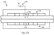
1つの実施形態では、共同電子システムは、磁気取り付けユニットを介して互いに強固に取り付けられた電子デバイスアレイの形態を取りうる。磁気取り付けユニットは複数の磁気取り付け特徴部を含みうる。複数の磁気取り付け特徴部のそれぞれは、対応する電子デバイスに含まれる対応する磁気取り付け特徴部と磁気で相互作用できる。1つの実施形態では、電子デバイスのアレイは、(モザイクの線に沿って)単一の統合ディスプレイとして機能できる。別の実施形態では、電子デバイスのアレイは(仮想キーボードのような)単一機能又は機能集合を提供できる。 In one embodiment, the collaborative electronic system may take the form of an electronic device array that is rigidly attached to each other via a magnetic attachment unit. The magnetic attachment unit may include a plurality of magnetic attachment features. Each of the plurality of magnetic attachment features can magnetically interact with a corresponding magnetic attachment feature included in a corresponding electronic device. In one embodiment, the array of electronic devices can function as a single integrated display (along the mosaic lines). In another embodiment, an array of electronic devices can provide a single function or set of functions (such as a virtual keyboard).
例として、第1電子デバイス及び第2電子デバイスは、磁気取り付けユニットを介して共に磁気で取り付けられうる。磁気取り付けユニットは磁気システムを含みうる。1つの実施形態では、磁気取り付けユニットは、第1電子デバイス及び第2電子デバイスのそれぞれにおいて磁気取り付けシステムを有効化するためのトリガとして機能しうる。1つの実施形態では、有効化は、磁気システムと磁気取り付けシステムのそれぞれとの間のキーとなる磁気相互作用の結果でありうる。1つの実施形態では、キーとなる磁気相互作用は、磁気システムの磁気素子の配置に基づく特性を有する磁界と、第1電子デバイス及び第2電子デバイスの磁気取り付けシステムとの間の相互作用の形態を取りうる。 As an example, the first electronic device and the second electronic device may be magnetically attached together via a magnetic attachment unit. The magnetic mounting unit may include a magnetic system. In one embodiment, the magnetic attachment unit may function as a trigger for enabling the magnetic attachment system in each of the first electronic device and the second electronic device. In one embodiment, the activation can be the result of a key magnetic interaction between each of the magnetic system and the magnetic mounting system. In one embodiment, the key magnetic interaction is a form of interaction between a magnetic field having characteristics based on the arrangement of the magnetic elements of the magnetic system and the magnetic mounting system of the first electronic device and the second electronic device. Can take.
1つの実施形態では、磁気取り付けユニットは、曲げ可能であるが頑丈である物質の形態を取りうる。このようにして、第1電子デバイスのディスプレイが約70°〜75°の快適な視覚角度でユーザに提示されつつ、第2電子デバイスがテーブルのような支持面に平らのまま留まるように、第1電子デバイスに磁気で取り付けられた磁気取り付けユニットの一部が曲げられうる。このようにして、第2電子デバイスは、共同システムにデータを入力するために用いられうる(仮想キーボード、GUIなどのような)入力を表示できる。1つの実施形態では、第1電子デバイスは、共同システムの現在の状態に従う視覚コンテンツを提示できる。 In one embodiment, the magnetic mounting unit may take the form of a material that is bendable but sturdy. In this way, the second electronic device remains flat on a support surface such as a table while the display of the first electronic device is presented to the user at a comfortable viewing angle of about 70 ° to 75 °. A part of a magnetic attachment unit magnetically attached to one electronic device can be bent. In this way, the second electronic device can display input (such as a virtual keyboard, GUI, etc.) that can be used to enter data into the collaborative system. In one embodiment, the first electronic device can present visual content according to the current state of the collaborative system.
例えば、第2電子デバイスは、入力コマンド及び/又はデータを提供するために用いられうる仮想キーボードを提示でき、第1電子デバイス及び第2電子デバイスの磁気取り付けによって共同システムへ提供できる。磁気取り付けユニットが例えば数学チュートリアルに関連する場合に、第1電子デバイス及び第2電子デバイスへ提供される情報は、第1電子デバイスのディスプレイに主題(解くべき数式、問題など)を提示させ、この主題に対して生徒は第2電子デバイスのディスプレイに提示された仮想キーボードを用いて相互作用できる。 For example, the second electronic device can present a virtual keyboard that can be used to provide input commands and / or data, and can be provided to the collaborative system by magnetic attachment of the first electronic device and the second electronic device. When the magnetic mounting unit is associated with a mathematical tutorial, for example, the information provided to the first electronic device and the second electronic device causes the display of the first electronic device to present the subject (formulas to be solved, problems, etc.) Students can interact with the subject using a virtual keyboard presented on the display of the second electronic device.
これらの実施形態及びその他の実施形態は、図1〜図35を参照して以下に検討される。しかしながら、これらの図面を参照して本明細書で与えられる詳細な説明は単に例示を目的とし、限定するものとして解釈されるべきではないことを当業者は容易に理解するだろう。この検討の残り部分について、記載される実施形態に従って互いに磁気で取り付くようにそれぞれ適切に構成された第1物体及び第2物体が説明される。しかしながら、任意の個数及び任意のタイプの適切に構成された物体が簡易かつ反復可能な方法で互いに磁気で取り付けられうることが留意されるべきである。特に、簡単及び明確化のために、この検討の残り部分について、第1物体は電子デバイス、特にハンドヘルド電子デバイスの形態を取ると仮定する。 These and other embodiments are discussed below with reference to FIGS. However, one of ordinary skill in the art will readily appreciate that the detailed description provided herein with reference to these drawings is for illustrative purposes only and should not be construed as limiting. For the remainder of this discussion, a first object and a second object, each appropriately configured to magnetically attach to each other according to the described embodiments, will be described. However, it should be noted that any number and any type of properly configured objects can be magnetically attached to each other in a simple and repeatable manner. In particular, for simplicity and clarity, it is assumed for the remainder of this discussion that the first object takes the form of an electronic device, particularly a handheld electronic device.
図1は、所望の反復可能な方法で互いに解放可能に取り付けられうる物品10及び電子デバイス12の簡略ブロック図である。より具体的に、物品10及び電子デバイス12は、外部の干渉なしに、かつ機械式留め具を使用せずに、事前に決定された位置及び相対的方向で互いに取り付きうる。物品10及び電子デバイス12は、これらの間の係合に打ち勝つ解放力が印加されるまで、互いに取り付けられたままでありうる。しかしながら、一部の場合に、物品10と電子デバイス12とが(ジッパのラインに沿って)連続的に取り外せることが望ましい場合があり、この場合に、物品10と電子デバイス12との間の1つの取り付け要素に関する係合を一度に外せる解放力が印加されうる。例えば、取り付け要素は、1つ目が物品10にあり、2つ目が電子デバイス12にある適切に適合された磁気素子のペアを含みうる。 FIG. 1 is a simplified block diagram of an
電子デバイス12は多くの形態を取りうる。例えば、電子デバイス12はポータブル電子デバイスの形態を取りうる。一部の例では、ポータブル電子デバイスは筐体15を含みうる。筐体15はポータブル電子デバイスのコンポーネントを囲み、当該コンポーネントへの支持を提供しうる。筐体15はまた、ポータブル電子デバイスの前面のかなりの部分を占める大型の目立つディスプレイへの支持を少なくとも提供できる。ディスプレイは、視覚コンテンツを提示するために用いられうる。視覚コンテンツは静止画像、ビジュアル、テキストデータ、さらにはグラフィカルユーザインタフェース(GUI)の一部として用いられるアイコンを含みうるグラフィカルデータを含みうる。 The
一部の場合に、ディスプレイの少なくとも一部はタッチセンサでありうる。タッチセンサによって、タッチイベントの最中に、(指、スタイラスなどのような)物体がディスプレイの上面に接触又は近接するように配置されうることが意味される。タッチイベントの細目(位置、圧力、期間など)は、処理のためにポータブル電子デバイスへ情報を提供するために用いられうる。一部の実施形態では、情報がポータブル電子デバイスへ提供されるのに加えて、またはこれに代えて、例えば触覚アクチュエータを用いてタクタイルにポータブル電子デバイスによって情報が提供されうる。しかしながら、電子デバイスは幅広く多様でありうるので、この構成は単なる例示であり、限定とすべきではないことが理解されるべきである。1つの例では、ポータブル電子デバイスは、カリフォルニア州クパチーノのアップルインクによって製造されるiPad(登録商標)のようなタブレットコンピュータである。 In some cases, at least a portion of the display can be a touch sensor. By touch sensor is meant that an object (such as a finger, stylus, etc.) can be placed in contact with or in close proximity to the top surface of the display during a touch event. The details of the touch event (position, pressure, duration, etc.) can be used to provide information to the portable electronic device for processing. In some embodiments, information may be provided by the portable electronic device to the tactile using, for example, a haptic actuator, in addition to or instead of being provided to the portable electronic device. However, it should be understood that this configuration is merely exemplary and should not be limited, as electronic devices can vary widely. In one example, the portable electronic device is a tablet computer such as iPad® manufactured by Apple Inc. of Cupertino, California.
物品10は幅広く多様であり、例えば電子デバイス12のアクセサリ又は付属品のような多くの形態を取りうる。アクセサリとして、物品10は、カバー、スタンド、ドック、吊り下げ具、入出力デバイスなどとして構成されうる。特に有用な形態では、物品10は、ポータブル電子デバイスのディスプレイ上に位置しうるフラップのような部材を含みうる保護カバーの形態を取りうる。電子デバイス12と同様に、物品10はまた、物品10のコンポーネントを囲み、当該コンポーネントこれへの支持を提供しうる筐体17を含みうる。 The
物品10及び電子デバイス12の一方又は両方は、取り付け特徴部を含みうる。例えば、物品10は取り付けシステム13を含み、電子デバイス12は対応する取り付けシステム14を含みうる。物品10と電子デバイス12とを解放可能に取り付けるように、取り付けシステム13は、対応する取り付けシステム14と共同できる。互いに取り付けられた場合に、物品10と電子デバイス12とは、単一の動作ユニットとして動作できる。他方で、取り外されたモードでは、物品10及び電子デバイス12は別々に動作でき、必要ならば、2つの個別の部品として動作できる。取り付けシステム13、14は、物品10と電子デバイス12とが所望の反復可能な方法で互いに取り付けられるように構成されうる。言い換えると、取り付けシステム13、14は、物品10と電子デバイス12とが一貫して互いに対して事前に決定された位置になるように、物品10と電子デバイス12とを共に反復してアライメントできる。 One or both of the
取り付け特徴部は幅広く多様でありうる。取り付けは、機械、電気、静電気、磁気、摩擦及び/又は同様のものを含む様々なタイプの結合によって提供されうる。1つの実施形態では、取り付けは物品及び/又は電子デバイスの外側からは見て取れない。例えば、物品及びデバイスは、見た目又は装飾的外観に悪影響を与える外部から視認可能な取り付け特徴部(例えば、スナップ、ラッチなど)を含むのではなく、物品又はデバイスの外側からは見て取れない取り付け特徴部を含んでもよく、それゆえ物品又はデバイスの見た目又は装飾的外観に影響しない。例として、取り付け特徴部は、物品又はデバイスの外面を乱さない引力面によって提供されうる。1つの実施形態では、取り付け特徴部の少なくとも一部は、引力の一部又は全部を提供するための磁気引力を利用する。 The attachment features can vary widely. Attachment can be provided by various types of coupling including mechanical, electrical, electrostatic, magnetic, friction and / or the like. In one embodiment, the attachment is not visible from the outside of the article and / or electronic device. For example, articles and devices do not include externally visible attachment features (eg, snaps, latches, etc.) that adversely affect the appearance or decorative appearance, but are not visible from the outside of the article or device. Thus not affecting the appearance or decorative appearance of the article or device. By way of example, the attachment feature can be provided by an attractive surface that does not disturb the outer surface of the article or device. In one embodiment, at least some of the attachment features utilize magnetic attraction to provide some or all of the attraction.
取り付けシステムは、1つ以上の取り付け特徴部を含みうる。複数の特徴部が用いられるならば、これらが固定する方法は同じであってもよいし、異なっていてもよい。例えば、1つの実装では、第1取り付け特徴部は第1取り付け手段を利用するが、第2取り付け特徴部は第1取り付け手段とは異なる第2取り付け手段を利用する。例えば、第1取り付け手段は摩擦結合を利用しうるが、第2取り付け手段は磁気を利用しうる。別の実装では、第1取り付け特徴部は第1取り付け手段を利用するが、第2取り付け特徴部は同じ又は同様の手段を利用する。例えば、第1取り付け手段及び第2取り付け手段は、磁石によって提供されうる。取り付け手段が同様でありうるけれども、特徴部の構成はシステムのニーズに依存して異なりうる。さらに、任意の個数及び任意の構成の取り付け手段が用いられうる。 The attachment system can include one or more attachment features. If a plurality of features are used, the method of fixing them may be the same or different. For example, in one implementation, the first attachment feature utilizes a first attachment means, while the second attachment feature utilizes a second attachment means that is different from the first attachment means. For example, the first attachment means may utilize frictional coupling while the second attachment means may utilize magnetism. In another implementation, the first attachment feature utilizes first attachment means, while the second attachment feature utilizes the same or similar means. For example, the first attachment means and the second attachment means can be provided by magnets. Although the attachment means can be similar, the configuration of the features can vary depending on the needs of the system. Furthermore, any number and any configuration of attachment means may be used.
説明される実施形態では、取り付けシステム13及び取り付けシステム14はそれぞれ、対応する取り付け特徴部13a/14aの第1集合と、対応する取り付け特徴部13b/14bの第2集合とを少なくとも含む。取り付け特徴部13aは、物品10と電子デバイスとを解放可能に取り付けるように、対応する取り付け特徴部14aと共同できる。1つの特定の実装では、これは磁気引力によって実現される。さらに、取り付け特徴部13bは、物品10と電子デバイスとを解放可能に更に取り付けるように、対応する取り付け特徴部14bと共同できる。1つの特定の実装では、これは磁気引力によって実現される。例として、取り付け特徴部13a/14aは第1位置に提供されうるが、取り付け特徴部13b/14bは第2位置に提供されうる。 In the described embodiment, each of the
特定の例では、取り付け特徴部14aは、取り付け特徴部13aと共同して、電子デバイス12を物品10に固定できる。別の例では、取り付け特徴部13bは取り付け特徴部14bを用いて物品10を電子デバイス12に固定できる。この例の取り付けシステム13、14は別々であってもよし、これらは取り付けを生み出すために共に共同してもよいことが留意されるべきである。これらが共同するならば、取り付け特徴部14a、14bは1つ以上の取り付け特徴部13a、13bに対応又は係合する。いずれの場合でも、これらの例の何れにおける取り付け特徴部も、機械取り付け、静電気取り付け、吸着取り付け、磁気取り付け及び/又は同様のものを通じて実現されうる。 In a particular example, the
取り付けシステムの配置及び取り付けシステム内の取り付け特徴部は幅広く多様でありうる。電子デバイス12に関して、取り付けシステム14は、前部、背部、上部、底部及び/又は側部に配置されうる。取り付け特徴部14a、14bは取り付けシステム14内の任意の位置に配置されうる。従って、取り付け特徴部14a、14bは筐体及び/又はディスプレイの対する任意の位置に配置されうる。1つの例では、取り付け特徴部14a、14bは筐体の1つ以上の側(例えば、上部、底部、左、右)に沿った係合を提供できる。別の例では、取り付け特徴部14a、14bは電子デバイス12の背部において係合を提供できる。更に別の例では、取り付け特徴部14a、14bは電子デバイス12の前部(例えば、存在するならば、ディスプレイが配置される場所)において係合を提供できる。一部の場合に、取り付け特徴部の組合せは例えば側部及び前部のような電子デバイス12の異なる領域に配置されうる。1つの実施形態では、取り付け特徴部14a、14bを含む取り付けシステム14は電子デバイス12の表面を乱さない。同様に、取り付けシステム13及び特に取り付け特徴部13a、13bは物品10の表面を乱さない。 The placement of the mounting system and the mounting features within the mounting system can vary widely. With respect to the
1つの実施形態によれば、取り付け特徴部は磁気素子を含みうる。磁気素子は、電子デバイス12に対して物品を係合配置に位置決めにするのを助けるように構成されうる。磁気素子はさらに、物品10及び電子デバイス12を係合に固定するのを助けうる。物品10と電子デバイス12との係合は、物品10及び電子デバイス12が個別の物体へ戻るように分離することを可能にする適切な解放力の印加によって分離されうることが留意されるべきである。しかしながら、磁気素子は、物品10及び電子デバイス12が任意の種類の機械的又は他の留め具を必要とせずにその後に結合を再開することを可能にできる。このようにして、磁気素子は物品10と電子デバイス12との間の反復可能で一貫した係合を提供する。 According to one embodiment, the attachment feature can include a magnetic element. The magnetic element can be configured to help position the article in an engaged configuration relative to the
物品10及び電子デバイス12はそれぞれ、コンポーネント16及びコンポーネント18を更に含みうる。コンポーネント16、18は典型的に物品10及び電子デバイス12の構成に依存し、例えば支持を提供するために用いられる機械的又は構造的コンポーネントであってもよいし、特定の動作/機能集合を提供できる動作的/機能的コンポーネントであってもよい。コンポーネントはこれらの個別のデバイスに専用であってもよいし、対応する物品又はデバイスの態様に(例えば、有線又は無線で)結合するように構成されてもよい。構造的コンポーネントの例は、フレーム、壁、留め具、補強材、運動機構(ヒンジ)などを含みうる。動作的コンポーネントの例は、プロセッサ、メモリ、バッテリ、アンテナ、回路、センサ、ディスプレイ、入力などを含みうる。必要な構成に依存して、コンポーネントは外部(すなわち、表面に露出する)にあってもよいし、及び/又は内部(例えば、筐体内に組み込まれる)にあってもよい。
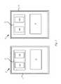
図2A及び図2Bは、1つの記載される実施形態に従って、磁気取り付けシステムを介して電子デバイス22に解放可能に取り付けられうる物品20の簡略透視図である。物品20及び電子デバイス22は一般に、図1に関して検討されたものに対応する。1つの実施形態では、磁気取り付けシステムは、(破線又は陰影で示される)磁気面24として実施されてもよく、より具体的には電子デバイス22の側部における磁気面24として実施されうる。磁気面24は、互いに近くに置かれた場合に物品20の対応する取り付け特徴部と共同できる磁界を提供する。磁界は、図2Bに示される係合面26に沿って物品20と電子デバイス22とを共に対をなす係合に引き付けることができる正味磁気引力を確立できる。 2A and 2B are simplified perspective views of an
言い換えると、磁気面24によって提供される磁界は、物品20と電子デバイス22との間の正味磁気引力が係合面26に実質的に直交するような特性を有しうる。さらに、磁界の結果として、物品20と電子デバイス22との間の正味磁気引力が係合面26に沿って一様に印加されうる。物品20と電子デバイス22とを解放するために、磁気取り付けシステムによって提供される正味磁気引力に打ち勝つための解放力が2つの取り付けられた物品に印加されうる。 In other words, the magnetic field provided by the magnetic surface 24 may have characteristics such that the net magnetic attraction between the
1つの側壁だけが示されるが、取り付けインタフェースの必要性に依存して、一部の場合に異なる側壁及び場合によっては側壁の組合せが用いられてもよいことも理解されるはずである。磁気取り付けの使用により留め具のような機械的取り付けの必要がなることが留意されるべきである。さらに、機械的取り付けがなく、磁気引力全体が一様なことによって、物品20及び電子デバイス22の表面が乱されないままになり、物品20と電子デバイス22とが単一の統合されたエンティティとして見えるように一体感のある外観を形成するのに役立つ。外観の一様性は、物品20及び電子デバイス22の両方の全体的な装飾的魅力を向上できる。 Although only one sidewall is shown, it should also be understood that different sidewalls and possibly combinations of sidewalls may be used in some cases, depending on the needs of the mounting interface. It should be noted that the use of magnetic attachments necessitates mechanical attachments such as fasteners. In addition, the absence of mechanical attachment and uniform overall magnetic attraction leaves the surface of
1つの実施形態では、磁気面は、電子デバイス22及び/又は物品20の側壁内の磁気取り付け特徴部の形態である磁気で引き寄せ可能な要素を組み込むことによって作製されうる。すなわち、磁気で引き寄せ可能な要素は物品20及び電子デバイス22の内部に、例えば電子デバイス22の筐体の内部に配置されうる。この構成では、筐体は、プラスチック又はアルミニウムのような非鉄金属のような非磁性物質で形成されうる。このようにして、磁力線は、筐体の壁を通じて作用するように構成されうる。磁気取り付け特徴部は、物品20及び電子デバイス22の外側表面の物理的外観を乱さない。物品20及び電子デバイス22の磁気で引き寄せ可能な要素は、物品20及び電子デバイス22を、対をなす係合に共に取り付ける磁気引力を生成するように互いに共同できる磁界を生み出すように構成されうる。磁気引力を生成するように構成された磁気引力は電子デバイス22と物品20との間の係合面26に直交する。 In one embodiment, the magnetic surface may be created by incorporating a magnetically attractable element in the form of a magnetic attachment feature in the
物体20及び電子デバイス22の対応する磁気素子間の磁気引力はまた、係合面26に沿って一様に印加されうる。係合面26に沿った磁気引力全体の一様性は、物品20及び電子デバイス22の対応する磁気素子間の分離距離の一様性を結果として生じうる。一様性はまた、物品20及び電子デバイス22の対応する磁気素子間の磁束密度の一貫性を結果として生じうる。正味磁気取り付けの一様性は、それぞれが互いによく一致した密着を形成する物品20及び電子デバイス22の表面によって容易になりうる。例えば、1つの表面は平らであるか、凹形状を有しつつ、他方の表面は一致する適合凸形状を有しうる。このようにして、共に密着することによって、物品20及び電子デバイス22の対応する磁気素子のそれぞれの間の分離距離は最小に低減されうる。表面形状の一致性はまた、係合面26の継ぎ目の外観を低減又は除去することによって、物品20及び電子デバイス22の見た目全体を向上できる。このシームレス品質は、物品20及び電子デバイス22が互いに取り付けられる場合に単一エンティティであるという錯覚を与えうる。 The magnetic attraction between the
見た目全体を向上することに加えて、磁気素子間の分離距離の一貫性は、物品20と電子デバイス22との間の取り付け力を係合面26に沿って一様にできる。このようにして、係合力は係合面26に亘って一様に分布され、そうでない場合に物品20と電子デバイス22との間の係合の完全性全体に影響するバックリング、ウィークポイントなどを防ぐことができる。 In addition to improving the overall appearance, the consistency of the separation distance between the magnetic elements can make the attachment force between the
図3A及び図3Bは、1つの記載される実施形態に従う磁気取り付けシステムを介して電子デバイス32に直接かつ解放可能に取り付けられうる電子デバイス30の形態を取りうる物品20の簡略透視図である。1つの実施形態では、磁気取り付けシステムは、(破線又は陰影で示される)磁気面34として実施されてもよく、より具体的には電子デバイス32の側部における磁気面34として実施されてもよい。磁気面34は、互いに近くに置かれた場合に電子デバイス30の対応する取り付け特徴部と共同できる磁界を提供できる。磁界は、図3Bに示されるような共同するシステム38を形成するように、係合面36に沿って電子デバイス30及び電子デバイス32を、対をなす係合に共に引き付けることができる正味磁気引力を確立できる。 3A and 3B are simplified perspective views of an
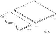
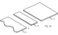
図4A及び図4Bは磁気取り付けユニット44及び対応する磁気システム46を介して電子デバイス42に解放可能に取り付けられうる物品40の簡略透視図である。この特定の実施形態は、以前はそれぞれの個別の側壁に直接に互いに取り付けられた物品40及び電子デバイス42を磁気で取り付けるために磁気取り付けユニット44が用いられる点を除いて、図2A及び図2Bに記載された実施形態と同様であることが留意されるべきである。このようにして、取り付けシステム46は物品40及び電子デバイス42にそれぞれ適した磁気取り付けを与えるように構成された複数の磁気取り付け特徴部を含みうる。 4A and 4B are simplified perspective views of an
図4Bは共同するシステム48を形成するために係合面47a、47bにおいて磁気取り付けユニット44を介して互いに磁気で取り付けられた物品40及び電子デバイス42を示す。システム48の一部として、電子デバイス42及び物品40は、物品40単体又は電子デバイス42単体では利用できない機能を提供するように互いに共同できる。例えば、物品40は電子デバイス42単体では利用できない機能をユーザへ提供できる吊り下げ装置、ドッキング装置、搭載装置などの形態を取りうる。1つの実施形態では、物品40は、磁気取り付けユニット44を介して電子デバイス42に磁気で取り付けられうるドッキングシステムの形態を取りうる。1つの実施形態では、ドッキングシステムは電子デバイス42の機械的支持を与えうる。1つの実施形態では、ドッキングシステムは電子デバイス42に情報を提供するように動作できる。1つの実施形態では、情報は磁気取り付けユニット44に組み込まれたストレージデバイスに格納されうる。1つの実施形態では、情報は(例えばWiFi接続によって)物品40で受信されてもよく、電子デバイス42へ磁気取り付けユニット44を介して渡されてもよく、その逆でもよい。 FIG. 4B shows the
1つの実施形態では、物品40は電子デバイス42を吊り下げるために用いられうる。例えば、物品40は、支持のために別の物体を掴むために用いられうるフック、留め具などを含みうる。物品40は、電子デバイス42の支持を提供するために用いられうる。例えば、物品40は、電子デバイス42に磁気で取り付けられうる連接型支持体の形態を取りうる。物品40の連接特性は、様々な角度及び方向に電子デバイス42を提示するために用いられうる。磁気取り付けユニット44と物品40との間の磁気取り付けの解放可能特性に起因して、電子デバイス42が用いられる場合に容易に取り外され、必要な場合にその後に再取り付けされうる。 In one embodiment, the
図5A及び図5Bは磁気取り付けユニット54を介して電子デバイス52に解放可能に取り付けられうる電子デバイス50の形態の物品40の簡略透視図である。この実施形態は、磁気取り付けユニット54が複数の磁気で引き寄せ可能な要素を含みうる点で図4A及び図4Bに示されたものと同様である。例えば、磁気素子は、電子デバイス50及び電子デバイス52のそれぞれにおいて磁気取り付けシステムを有効化するのに適した磁気面56a及び磁気面56bを生成するように、磁気取り付けユニット54内に配置されうる。例えば、電子デバイス52における磁気取り付けシステムの有効化の結果として、磁気面58が電子デバイス52の側壁において提示されうる。磁気面58は、磁気取り付けユニット54及び電子デバイス52を係合面60aにおいて磁気で取り付けるために用いられうる。1つの実施形態では、磁気面56bは磁気取り付けユニット54の反対の側壁において生成されうる。電子機器54と殆ど同様にして、磁気面56bは、図5Bに示される共同するシステム62を生成する係合面60bにおいて電子デバイス50に磁気取り付けユニット54を磁気で取り付けるのに適した磁気面を生成する電子デバイス50の磁気取り付けシステムを有効化するために用いられうる。 FIGS. 5A and 5B are simplified perspective views of an
しかしながら、電子デバイス50と電子デバイス52との間の側面同士の磁気取り付けが示されたが、一部の実施形態では、磁気面は電子デバイス50、52の底面及び/又は上面に位置してもよいことが留意されるべきである。例えば、磁気取り付けユニット54の磁気素子は磁気取り付けユニット54の上面64の裏側に組み込まれ、背面同士の構成を形成する電子デバイス50又は電子デバイス52の背面に取り付けるための磁気面66を形成する。図示されていないが、磁気取り付けユニット54の底面に追加の磁気素子が組み込まれてもよいことが留意されるべきである。 However, although side-to-side magnetic attachment between
図5Bは共同するシステム62を形成するために互いに磁気で取り付けられた電子デバイス50及び電子デバイス52を示す。この構成では、電子デバイス52及び電子デバイス50は、電子デバイス50単体又は電子デバイス52単体では利用可能でない機能を提供するように互いに共同できる。例えば、電子デバイス50は、例えばユーザからの入力コマンド及び/又は例えばセンサからの入力データの形態の情報を受信できる。電子デバイス50は全体的に又は部分的に情報を処理でき、処理された情報を更なる処理のために電子デバイス52に渡せる。このようにして、共同するシステム62は情報をより効率的な方法で処理でき、単体で動作する電子デバイス50又は電子デバイス52から予期されるものを超える向上したユーザ体験を提供するコンピュータリソースを維持する。 FIG. 5B shows
共同するシステム62は、磁気取り付けユニット54の側部の磁気面56a、56bがそれぞれ電子デバイス52、50の磁気取り付けシステムを有効化するように、磁気取り付けユニット54と電子デバイス50、52とを互いに近接して配置することによって形成されうる。有効化した磁気システムは、その後、共同するシステム62を形成するために電子デバイス50及び電子デバイス52を、対をなす係合に維持するのに十分な大きさ及び方向の正味磁気引力を生成するように磁気取り付けユニット54と相互作用する(磁気面58のような)磁気面を提供する。 The cooperating
1つの実施形態では、磁気取り付けユニット54は剛性部材で形成されうる。1つの実施形態では、磁気取り付けユニット54は曲げ可能である。1つの観点では、磁気取り付けユニット54の曲げ可能な性質は、75°のような視覚的に快適な角度で提示されうるキーボード及びディスプレイのようなユーザインタフェースをユーザに提供するために用いられうる。 In one embodiment, the
磁気素子の目的は同様、すなわち物品を電子デバイスに取り付けることや、電子デバイスを電子デバイスに取り付けることであるが、これらの機構は幅広く多様でありうることが理解されるべきである。一部の場合に、磁界は異なるように構成されうる。例として、側部に搭載された磁気面が第1磁力を提供してもよく、前部に面する磁気面が第1磁力とは異なる第2磁力を提供してもよい。これは、異なる保持要件だけでなく、異なる表面積すなわち利用可能なスペース、及び電子デバイスの内部コンポーネントへの影響に部分的に起因しうる。1つの例では、側部に搭載された磁気面は、物品(又は電子デバイス)を電子デバイスに固定するためのより大きな保持力(すなわち、主固定力)を提供し、前部に面する磁気面は副固定力である。 The purpose of the magnetic element is similar, i.e., attaching an article to an electronic device, or attaching an electronic device to an electronic device, but it should be understood that these mechanisms can be widely varied. In some cases, the magnetic field can be configured differently. As an example, a magnetic surface mounted on the side may provide a first magnetic force, and a magnetic surface facing the front may provide a second magnetic force different from the first magnetic force. This may be due in part to different retention requirements, as well as the impact on different surface areas, ie available space, and internal components of the electronic device. In one example, the magnetic surface mounted on the side provides a greater holding force (ie, the main fixing force) for securing the article (or electronic device) to the electronic device, and the magnetic surface facing the front. The surface is a secondary fixing force.
1つの例では、磁気取り付けユニット54は、磁気取り付けユニットを可動及び可撓性を有するように半剛性であり互いに対して曲がる複数区間を含む。1つの実施形態では、磁気取り付けユニット54は、1つ以上の異なる構成に折り重なり、一部の場合に上述されたものと同様の磁気システムを用いてこれらの構成に保持されうる。これらの実施形態及びその他の実施形態は以下に詳細に記載される。さらに、記載される実施形態は本明細書に具体的に記載されるものに限定されず、例えば吊り下げ装置として用いられるアクセサリデバイス、ディスプレイの視覚性を向上するための電子デバイス用の支持機構、及びディスプレイのタッチセンサ部のための支持機構及びタッチセンサ部におけるタッチイベントを入力するための支持機構などを含む他の構成として用いられうる。 In one example, the magnetic mounting
電子デバイス及び物品は多くの形態を取りうる。この議論の残り部分について、電子デバイスはハンドヘルドポータブル計算デバイスの観点で記載される。従って、図6は記載される実施形態に従う電子デバイス100の上面透視図を示す。電子デバイス100はデータを処理でき、より具体的にはオーディオ、ビジュアル、画像などのようなメディアデータを処理できる。例として、電子デバイス100は一般に、スマートフォン、音楽プレーヤ、ゲームプレーヤ、ビジュアルプレーヤ、携帯情報端末(PDA)、タブレットコンピュータなどとして動作できるデバイスに対応しうる。電子デバイス100はまた、ハンドヘルドでありうる。ハンドヘルドであることに関して、電子デバイス100は一方の手で保持されつつ、他方の手で操作可能である(すなわち、デスクトップのような基準面は必要ない)。従って、電子デバイス100は一方の手で保持されつつ、他方の手によって動作入力コマンドが提供されうる。動作入力コマンドは、ボリュームスイッチ、ホールドスイッチを操作することを含み、又はタッチセンサディスプレイデバイス又はタッチパッドのようなタッチセンサ面への入力を提供することによって操作することを含みうる。 Electronic devices and articles can take many forms. For the remainder of this discussion, the electronic device is described in terms of a handheld portable computing device. Accordingly, FIG. 6 shows a top perspective view of the
電子デバイス100は筐体102を含みうる。一部の実施形態では、筐体102は、鋳造、モールド又は他の方法で所望の形状に形成されうるプラスチック又は非磁気金属のような任意の個数の材料で形成された一体成型の筐体の形態を取りうる。電子デバイス100が金属筐体を有し、高周波(RF)ベースの機能を組み込む場合に、筐体102の一部はセラミックやプラスチックのような無線透過材料を含みうる。筐体102は複数の内部コンポーネントを囲むように構成されうる。例えば、筐体102は、電子デバイス100のための計算動作を提供するために(集積回路チップを含む)様々な構造コンポーネント及び電気コンポーネントを囲み、支持できる。集積回路は、チップ、チップセット又はプリント回路基板(PCB)又は他の支持構造体に搭載された面でありうるモジュールの形態を取りうる。例えば、メインロジックボード(MLB)は、少なくともマイクロプロセッサ、(FLASHのような)半導体メモリ及び様々な支持回路などを含みうる集積回路を搭載しうる。筐体102は、内部コンポーネントを配置するための開口104を含んでもよく、必要ならば視覚コンテンツを提示するためのディスプレイアセンブリを収納するためのサイズを有してもよく、ディスプレイアセンブリは保護層106によってカバーされて保護される。一部の場合に、ディスプレイアセンブリは、電子デバイス100に制御信号を提供するために用いられうる触覚入力を可能にするタッチセンサでありうる。一部の場合に、ディスプレイアセンブリは、電子デバイスの前部の敷地の大部分をカバーする大きな目立つディスプレイエリアであってもよい。 The
電子デバイス100は、電子デバイス100を少なくとも1つの適切に構成された他の物体に磁気で取り付けるために用いられうる磁気取り付けシステムを含みうる。 The
磁気取り付けシステムは、筐体102内に分散され、一部の場合に筐体102に接続された複数の磁気取り付け特徴部を含みうる。例えば磁気取り付けシステムは、側壁102aの近くに配置された第1磁気取り付け特徴部と、カバーガラス106の下に配置された第2磁気取り付け特徴部とを含みうる。1つの実施形態では、第1磁気取り付け特徴部は複数の状態で動作できる。例えば、無効状態では、第1磁気取り付け特徴部は側壁102aの外面において第1磁気面M1を提供できる。第1磁気面M1は、側壁102aの外面に配置された磁気の影響を受けやすいデバイスにほとんど影響を与えないか、まったく影響を与えず、磁気取り付けに適さない磁界を示しうる。言い換えると、磁気面M1は式(1)を満たす側壁102における磁束密度Bに一致する。
B≦Bthreshold 式(1)
ここで、Bthresholdは、側壁102aにおいて磁気取り付けを促進せず、側壁102aにおいて磁気の影響を受けやすいデバイスに実質的に影響を与えない側壁102aにおける磁束漏洩の値に対応する磁束密度Bの値を表す。The magnetic attachment system may include a plurality of magnetic attachment features distributed within the
B ≦ Bthreshold formula (1)
Where Bthreshold is the value of magnetic flux density B corresponding to the value of magnetic flux leakage at
しかしながら、有効状態において、第1磁気取り付け特徴部は図6Bに斜めハッチングで示される側壁102の外面における第2磁気面M2を提供できる。磁気面M2は式(2)を満たす側壁102の外面における磁気取り付けを促進することに一致する。
B>Bthreshold 式(2)However, in the effective state, the first magnetic attachment feature can provide a second magnetic surface M2 on the outer surface of the
B> Bthreshold formula (2)
1つの実施形態では、適切な磁気特性を有する外部磁界は第1磁気取り付けシステムを無効状態から有効状態に移行させうる。このようにして、側壁102aに表現される磁気面は(図6Aに示される)磁気面M1から(図6Bに示される)磁気面M2に変化しうる。外部磁界は、第1磁気取り付け特徴部の動作状態を無効から有効に変化させる第1磁気取り付け特徴部と共同する電子デバイス100の外にある磁気取り付け特徴部によって提供されうる。 In one embodiment, an external magnetic field with suitable magnetic properties can cause the first magnetic mounting system to transition from a disabled state to a enabled state. In this way, the magnetic surface represented on the
第2磁気取り付け特徴部は、式(2)を満たす磁気面M3を提供することによって、電子デバイス100の別のデバイスへの磁気取り付けを支援できる。1つの実施形態では、第2磁気取り付け特徴部は、磁気面M3の提供に一致する1つの動作状態を有する。 The second magnetic attachment feature can assist in magnetic attachment of the
明示されないが、磁気取り付けシステムの様々な磁気取り付け特徴部が筐体102の任意の適切な位置に配置されうることが理解される。例えば、磁気取り付け特徴部は筐体102の内部底面に配置されてもよいし、筐体102の側部102c、102dに沿って配置されてもよい。 Although not explicitly shown, it is understood that the various magnetic attachment features of the magnetic attachment system can be located at any suitable location on the
図7A−図7Bに示され、図5A−図5Bに関して上述された説明を再び参照して、磁気取り付けユニット54は、係合面132a、132bにおいて共同するシステム130を形成するために電子デバイス100、120を磁気で取り付けるために用いられうる。共同するシステム130は電子デバイス100と電子デバイス120との両方からのリソースを単独で又は組み合わせて利用できる。1つの実施形態では、電子デバイス100は、対応する情報を電子デバイス120に無線送信することによってタッチイベントに応答できる仮想キーボードを提示できる。電子デバイス120は応答を提供するために当該情報を使用できる。例えば、ユーザは電子デバイス100によって提示されたアイコンのリストから特定のメディアアイテム又はアイテム群を選択できる。選択されたメディアアイテム(群)の識別は(無線で又は有線接続を介して)電子デバイス120へ転送されうる。1つの実施形態では、電子デバイス120は、選択されたメディアアイテムの少なくとも一部を復号して提示できる。 Referring back to the description shown in FIGS. 7A-7B and described above with respect to FIGS. 5A-5B, the
図8A〜図8Cは、電子デバイス100を、適切に構成された磁気取り付けシステムを有する物体に磁気で取り付けるために用いられうる磁気取り付けユニット200の様々な実施形態を示す。物体はアクセサリデバイスの形態をとりうる。物体は電子デバイスの形態をとりうる。一部の場合に、アクセサリデバイスは電子デバイス100と通信できる電子コンポーネントを含んでもよく、その逆も成り立つ。いずれの場合でも、磁気取り付けユニット200は可撓性部材206を介して共に接続された磁気取り付け特徴部202、204を含みうる。1つの実施形態では、磁気取り付け特徴部202、204は可撓性部材206に固定して取り付けられうる。1つの実施形態では、磁気取り付け特徴部202、204は可撓性部材206に旋回可能に接続され、それによって磁気取り付けユニット200に追加の自由度を提供できる。 8A-8C illustrate various embodiments of a
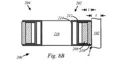
図8Aは記載される実施形態に従う磁気取り付け特徴部202、204の横断面図を示す。この特定の説明では、磁気取り付け特徴部202、204は、略平坦な面を有する筐体102の一部に磁気で取り付けられる。しかしながら、筐体102は曲面を有してもよく、この場合に、以下に記載される磁気取り付け特徴部202、204の様々なコンポーネントの形状は、筐体102の形状に一致する形状を取りうることが留意されるべきである。このようにして、筐体102内の対応する磁気素子と磁気取り付け特徴部202、204との間の分離距離が最小化され、それによって正味磁気引力が最大化される。 FIG. 8A shows a cross-sectional view of magnetic attachment features 202, 204 in accordance with the described embodiments. In this particular description, the magnetic attachment features 202, 204 are magnetically attached to a portion of the
以下の記載において、磁気取り付け特徴部202、204は実質的に同じ構成を有することが留意されるべきである。しかしながら、一部の実施形態では、共に磁気で取り付けられる物体の性質及び形態に依存して、磁気取り付け特徴部202、204は構造において幾分異なりうる。従って、簡単のために、磁気取り付け特徴部202だけが記載される。 In the following description, it should be noted that the magnetic attachment features 202, 204 have substantially the same configuration. However, in some embodiments, depending on the nature and form of the objects that are magnetically attached together, the magnetic attachment features 202, 204 may differ somewhat in structure. Thus, for simplicity, only the
電子デバイス100の磁気素子は対応する磁気素子204と磁気で相互作用できる。1つの実施形態では、磁気素子208は約2mmの厚さを有し、筐体102のものに実質的に一致する形状を有しうる。磁気素子208と電子デバイス100の磁気素子との間の磁気相互作用は、筐体102の厚さtとラベル210の厚さ「l」との合計にほぼ等しい分離距離Xsepに一致する正味磁気引力を生成できる。厚さ「l」は約0.2mmのオーダでありうる。ラベル210は、起こりうる引っ掻き及び磁気素子208と筐体102との間の金属対金属接触によって生じる可能性がある他の装飾的損傷から筐体102の外面を保護するために用いられうる。ラベル210と磁気素子208との両方はそれぞれ、筐体102の形状に一致する形状を有しうる。このようにして、磁気素子208と電子デバイス100の磁気素子との間の距離は、筐体102の厚さtとラベル210の厚さlとにおおよそ低減されうる。The magnetic elements of the
磁気分路212は、筐体102から見て外側を向く磁気素子208の部分に接着され、当該部分を囲みうる。磁気分路212は鋼鉄又は鉄のような磁気的に活性な金属で形成されうる。磁気的に活性な材料は、これがなければ電子デバイス100の磁気素子から離れた方向に向くだろう磁束線を方向変更でき、それによって磁気取り付け特徴部202と電子デバイス100との間の全磁束密度Bを増加する。その後、磁気分路212は磁気取り付け特徴部202の筐体214に接着されうる。(金属対金属接触を避けるために)ラベル210だけが筐体214に接触することを保証するために、ラベル210は約距離「d」だけ筐体102へ出っ張る(すなわち、突出する)。名目的に、距離dは約0.1mmのオーダでありうる。 The
図8Bは磁気取り付け特徴部202、204が剛性部材216に結合される磁気取り付け特徴部200の実施形態を示す。上述のように、磁気取り付け特徴部202、204は剛性部材216に固定して取り付けられうる。1つの実施形態では、磁気取り付け特徴部202、204は剛性部材216に旋回可能に接続されうる。 FIG. 8B shows an embodiment of a
図8Cは磁気取り付け特徴部202、204が(剛性又は可撓性を有しうる)接続部材222に組み込まれる磁気取り付けユニット220の形態の磁気取り付けユニットの別の実施形態を示す。この構成では、筐体214は必要ない。従って、磁気素子208、ラベル210及び分路212だけが必要となる。 FIG. 8C shows another embodiment of a magnetic attachment unit in the form of a
この検討の残り部分は磁気取り付けシステムを使用できるデバイスの特定の実施形態を記載する。特に、電子デバイス100はカリフォルニア州クパチーノのアップルインクによって製造されるiPadのようなタブレットコンピューティングデバイスの観点で以下に記載される。 The remainder of this discussion describes specific embodiments of devices that can use magnetic mounting systems. In particular, the
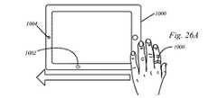
1つの実施形態では、アクセサリデバイス120は電子デバイス100の機能全体を向上するために用いられうる。例えば、アクセサリデバイス120は吊り下げ装置として動作するように構成されうる。電子デバイス100に磁気で取り付けられた場合に、アクセサリデバイス120は電子デバイス100を吊り下げるために用いられうる。このようにして、電子デバイス100は、壁に又は天井からぶら下げて美術品、動画、写真などのような視覚コンテンツを提示するためのディスプレイとして用いられうる。吊り下げ装置として、電子デバイス100は、正味磁気引力FNETに打ち勝つのに十分な解放力を単に発揮するだけで簡単に取り外されうる。アクセサリデバイス120はその場に残されてもよく、後で電子デバイス100(又は別のデバイス)を再度取り付けるために用いられうる。In one embodiment, accessory device 120 may be used to improve the overall functionality of
1つの実施形態では、アクセサリデバイス120はまた、電子デバイス100に磁気で取り付くために自身に備えられていない物体を取り付けるための保持機構の形態を取りうる。例えば、アクセサリデバイス120はスタイラス又は他のこのような入力デバイスを運ぶように構成されうる。スタイラスは電子デバイスに入力を与えるために用いられうる。一部の場合に、アクセサリデバイス120はスタイラスの存在を示す信号を電子デバイス100に提供できる。信号は、例えば電子デバイス100をスタイラス認識状態に移行させうる。より具体的に、アクセサリデバイス120が電子デバイス100に磁気で取り付けられた場合に、電子デバイス100はスタイラスタイプの入力を認識するためにスタイラス入力状態を有効化できる。アクセサリデバイス120が外された場合に、電子デバイス100はスタイラス入力状態を無効化できる。このようにして、スタイラスは必要な場合に便利に電子デバイス100に取り付け/取り外しされうる。 In one embodiment, accessory device 120 may also take the form of a retention mechanism for attaching an object that is not provided for magnetic attachment to
アクセサリデバイス120は電子デバイス100の機能を向上するために用いられる支持体の形態をとりうる。例えば、アクセサリデバイス120は75°のような快適な視覚角度で電子デバイス100のディスプレイが見られうるディスプレイスタンドとして動作するように構成されうる。言い換えると、テーブル又はデスクのような水平面に置かれた場合に、アクセサリデバイス120は、ディスプレイに提示される視覚コンテンツが約75°の視覚角度で見られるように、電子デバイス100を支持できる。 The accessory device 120 may take the form of a support that is used to improve the functionality of the
アクセサリデバイス120はまた、キーボード状態にある電子デバイス100の機能を向上するために用いられる支持体の形態をとりうる。キーボード状態では、アクセサリデバイス120は人間工学的にフレンドリな角度でタッチパッド面を提示するために用いられる。このようにして、入力タッチイベントは、ユーザの手首、手、腕などを酷使しない角度で(例えば仮想キーボードに)適用されうる。 The accessory device 120 can also take the form of a support that is used to enhance the functionality of the
図9は開いた形態の可撓性磁気取り付けユニット306を介してタブレットデバイス302とタブレット304とを磁気で取り付けることによって形成される装置300を説明する。磁気取り付けユニット306は、旋回ヒンジアセンブリ310、312を互いに接続するように構成された可撓性接続部材308を含みうる。旋回ヒンジアセンブリ310、312のそれぞれはその後タブレットデバイス304、302にそれぞれ磁気で接続される。ヒンジアセンブリは、磁気取り付けユニット306がデバイス302、304に磁気で取り付けられている間に、磁気取り付けユニット306が折り重なることを可能にする1つ以上の旋回軸を提供できる。 FIG. 9 illustrates an
1つの実施形態では、ヒンジアセンブリ310は、(第1端部ラグとも呼ばれる)第1ヒンジ部314と、第1端部ラグの反対に配置された第2ヒンジ部(又は第2端部ラグ)316とを含みうる。第1端部ラグ314は、追加の旋回軸を提供する接続部材308に組み込まれた接続ロッド(不図示)を介して第2端部ラグ316に強固に接続されうる。接続ロッドはタブレットデバイス302、304を強固に支持するのに十分に強い金属又はプラスチックで形成されうる。 In one embodiment, the
ヒンジスパン318は磁気素子を含みうる。磁気素子はタブレットデバイス302、304の磁気素子の対応する構成を有する磁気取り付け特徴部にヒンジスパン318を磁気で取り付けるように配置されうる。より具体的に、ヒンジスパン318内の磁気素子は、タブレットデバイス302の磁気特徴部を有効化して、これらをヒンジスパン318に磁気で取り付けられるようにする。ヒンジスパン318はプラスチックやアルミニウムのような非磁気金属のような磁気的に不活性な材料で形成されうる。 The
装置300は各タブレットデバイス302、304が本のように視覚情報を提示できる本として参照されうる。例えば、図9に示されるように、開いた形態では、装置300は、タブレットデバイス302のディスプレイ320が開いた本のページのように機能できる(タブレット304のディスプレイ322も同様に機能できる)開いた本に似ている。1つの実施形態では、例えば左から右へのページフリップジェスチャを用いて前方へフリップするようにタブレットデバイス302(又はタブレットデバイス304)のタッチセンサ面を単にスワイプするだけで、ユーザはページを「フリップ」できる。一方、ページ(又はページ群)を後方にフリップするために、ユーザは例えば右から左へのページフリップジェスチャを用いてタブレットデバイス302又は304のタッチセンサ面をスワイプできる。 The
いずれの場合でも、図9に示される本モードでは、本への合理的な類似及び本が情報を提示する方法を提供するためにタブレットデバイス302、304は互いに通信しなければならない。この通信はタブレットデバイス302、304間の無線通信の形態をとりうる。 In any case, in the present mode shown in FIG. 9, the
図10は、互いに折り重なるようにタブレットデバイス302、304が可撓性接続部材306の可撓性を用いる閉じた形態にある装置300を示す。1つの実施形態では、ディスプレイ320、322の下にある磁気素子は、タブレットデバイス302,304が互いに接触するのを妨げるように構成されうる。1つの構成では、磁気素子はタブレットデバイス302とタブレットデバイス304との間の接触を妨げるこれらのデバイス間の正味磁気斥力を生成するような方法で相互作用するように構成されうる。1つの実施形態では、磁気素子は、タブレットデバイス302、304を互いに固定できる正味磁気引力を生成するように構成されうる。1つの実施形態では、磁気素子は、閉じた形態において磁力をほとんど提供しないか全く提供しないように構成されうる。 FIG. 10 shows the
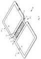
図11A及び図11Bは磁気取り付けユニット330を介して互いに磁気で取り付けられたタブレットデバイス302、304を示す。1つの実施形態では、磁気取り付けユニット330は、ヒンジ(又はクラッチバレル)338を介して互いに旋回可能に接続された剛性部334、336で形成された接続部材332を含みうる。図11Aに示されるように、タブレットデバイス302はテーブルのような平坦な支持面に置かれうる。タブレットデバイス304はその後タブレットデバイス302に対して垂直な方向に配置されうる。このようにして、タブレットデバイス304は視覚コンテンツを提示するためのディスプレイとして機能できる。 11A and 11B
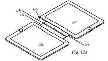
図12Aは磁気取り付けユニット340を介して共に接続されたタブレットデバイス302、304を示す。示されるように、磁気取り付けユニット340はヒンジアセンブリ318を含まず、よってタブレットデバイス302、304に固定して取り付けられる。磁気取り付けユニット340は、クラッチバレル又はヒンジ338を介して互いに旋回可能に接続された剛性接続部材342を含みうる。このようにして、図12Bに示されるように、タブレットデバイス302はテーブルのような平坦な支持面に置かれ、(タブレット304のような)別の電子デバイスはディスプレイとして機能するように配置されうる。図12B及び図12Cから見て取れるように、タブレットデバイス304は、必ずしもタブレットデバイスではない電子デバイス100によって置き換わりうる。例えば、電子デバイス100は、磁気取り付けユニット340に磁気で取り付けることができる単なるディスプレイの形態をとりうる。1つの実施形態では、磁気取り付けユニット340は実際に電子デバイス100の一部として形成されうる。このようにして、磁気取り付けユニット340はタブレットデバイス302に磁気で取り付けるのに適した単一の磁気取り付け特徴部だけを含みうる。 FIG. 12A shows
図12Cに示されるように、立てられた電子デバイスが電子デバイス100の形態をとるかタブレットデバイス340の形態をとるかに係わらず、立てられた電子デバイスへの追加の支持を提供するために支持構造体350が用いられうる。 As shown in FIG. 12C, support is provided to provide additional support to the raised electronic device, regardless of whether the raised electronic device takes the form of the
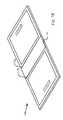
図13はタブレットアレイ360を形成するためにタブレットデバイス302、304を磁気で取り付けた磁気取り付けユニット220を示す。従って、タブレットデバイス302、304は無線接続を介して互いに通信できる。1つの実施形態では、無線接続は、タブレットデバイス302、304が互いに直接に通信できるWiFi無線通信の形態をとりうる。1つの実施形態では、タブレットデバイス302、304は、無線ルータ、サーバコンピュータのような外部回路を部分的に介して互いに通信できる。1つの実施形態では、磁気取り付けユニット220はタブレットデバイス302、304間の通信を支援するための通信リソースを提供できる。1つの実施形態では、磁気取り付けユニット220は処理リソースだけでなく、タブレットデバイス302、304の一方又は両方の動作状態を変えるために用いられうるデータストレージリソースを含みうる。例えば、磁気取り付けユニット220が(フラッシュメモリのような)データストレージデバイスを含む場合に、ストレージデバイス内のデータはタブレットデバイス302、304の一方又は両方に転送されうる。転送されたデータは、個別のタブレットデバイスの動作状態を変えるために実行されうる命令の形態をとりうる。 FIG. 13 shows a
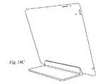
図14Aは実施形態に従うシステム400の断面図を示す。システム400は磁気ヒンジアセンブリ406を介してカバーアセンブリ404に磁気で取り付けられたタブレットデバイス402を含みうる。カバーアセンブリ404は、旋回軸410においてヒンジアセンブリ404に旋回可能に取り付けられたセグメント化カバー408を含みうる。ヒンジアセンブリ406はヒンジアセンブリ404の磁気素子412とタブレットデバイス402の磁気取り付け特徴部414とを介してタブレットデバイス402に磁気で取り付けられうる。介在層416はヒンジアセンブリ406とタブレットデバイス402の筐体418との間の直接の金属対金属接触を防ぐように機能できる。 FIG. 14A shows a cross-sectional view of a
カバーアセンブリ404はまた、旋回軸422においてヒンジアセンブリ406に旋回可能に取り付けられた別個のフラップ部420を含みうる。このようにして、セグメント化カバー408とフラップ部420は図14Bに示されるようにそれぞれの旋回軸の周りを回転でき、セグメント化カバー408は支持構造体424になるように折り重ねられる。支持構造424は三角形の形状であってもよく、ディスプレイ426が約75°の角度で提示されるようにタブレットデバイス402を配置するために用いられうる。
フラップ部420はファブリックのような可撓性部材で形成されうる。1つの実施形態では、フラップ部420は様々な入力デバイスを含みうる。例えば、図15に示されるように、フラップ部420はキーボード430を含みうる。キーボード430は例えば有線接続を用いてタブレットデバイス402と通信状態にありうる。1つの実施形態では、キーボード430はタブレットデバイス402と無線通信状態にありうる。従って、ユーザは、ファブリックキーボード430の様々な入力キーを押下することによってタブレットデバイス402へ情報を渡すことができる。 The
フラップ部420は任意の適切なタイプの入力デバイスを含むように構成されうることが留意されるべきである。例えば、図16に示される1つの実施形態では、フラップ部420は入力パッド440の形態をとりうる。入力パッド440は、スタイラス、ペン、鉛筆又は指のような人間の付属器官により提供されるもののようなタッチイベントを感知可能でありうる。さらに、図17に更に示されるように、フラップ部420は、所定の方法でユーザがタッチパッド450にタッチすることによってタブレットデバイス402に情報を提供するために用いられうるタッチパッド450を含みうる。 It should be noted that the
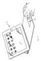
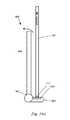
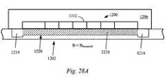
図18A〜図18Dは記載される実施形態に従う磁気ドッキングステーション500を示す。磁気ドッキングステーション500は支持体502及びベース部504を含みうる。ベース部504は電子デバイス400の磁気取り付け特徴部を有効化するように構成された磁気素子506を含みうる。従って、ベース部504のスロット508に電子デバイス100を置くことの結果として、磁気素子506が電子デバイス100の磁気取り付け特徴部を有効化しうる。この有効化により、ドッキングステーション500に電子デバイス100を固定するのに十分に強い磁気素子506と電子デバイス100との間の正味磁気引力が生じうる。図17Bに示される1つの実施形態では、電子デバイス100はタブレットデバイス302の形態をとりうる。1つの実施形態では、ドッキングステーション500は電子デバイス100に電力を提供できる。1つの実施形態では、ドッキングステーション500と電子デバイス100とは、WiFi、BlueTooth等のような適切な無線通信デバイスを介して互いに無線で通信できる。1つの実施形態では、ドッキングステーション500は、電子デバイス100とドッキングステーション500に接続された別の電子デバイス、又は一部の場合にキーボード、キーパッド、タッチパッド等のような入力デバイスとの間の有線通信チャネルを提供するドッキングポート(群)を含みうる。図18A〜図18Dに示される実施形態では、キーボードのような入力デバイスが配置されうるテーブル又はデスクのような支持面に対して実質的に固定された角度及び方向で電子デバイス100が提示されるようにドッキングステーション500が固定される。 18A-18D show a
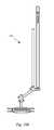
しかしながら、図19Aに示されるように、ドッキングステーション600は旋回軸602の周りを旋回できる。このようにして、電子デバイス100は支持面に対して任意の個数の角度で提示されうる。旋回するドッキングステーション600は、回転軸602を介して支持体606に旋回可能に接続されたベース部604を含みうる。1つの実施形態では、磁気素子610は、電子デバイス100を旋回するドッキングステーション600に磁気で結合するために電子デバイス100の磁気取り付け特徴部612を有効化できる。1つの実施形態では、磁気素子610はベース部604に含まれうる。図19Bは電子デバイス100がタブレットデバイス302の形態をとる実施形態を示す。図19Cは本発明の実施形態に従う連接型ドッキングステーション650を示す。 However, as shown in FIG. 19A, the
図20A〜図20Dは記載される実施形態に従うタブレットデバイス302に磁気で取り付けられうる様々な吊り下げアクセサリ700を示す。示されるように、吊り下げアクセサリはそれぞれ、タブレットデバイス302に含まれる磁気取り付け特徴部を有効化するように構成された磁気素子を含むように形成されることが留意されるべきである。この統合構成は必要なコンポーネント数を低減しうる。しかしながら、1つの実施形態では、吊り下げアクセサリは上述の磁気取り付けユニットを用いてタブレットデバイス302に磁気で取り付けられうる。いずれの場合も、様々な吊り下げアクセサリは任意の適切な面からタブレットデバイス302を吊り下げるか、他の方法でぶら下げるために用いられうる。例えば、図20A及び図20Bは垂直な壁からタブレットデバイス302をぶら下げるのに適した吊り下げアクセサリ700の変形を示す。例えば、フックアクセサリ702及び吸着カップアクセサリ704は、フックアクセサリ702の場合にオフィスのパーティションにある垂直な壁から、図20Bに示される吸着カップアクセサリ704の場合に冷蔵庫のドア、黒板又はホワイトボードからタブレットデバイス302を吊り下げるために用いられうる。 20A-20D illustrate various hanging accessories 700 that can be magnetically attached to the
図20C及び図20Dはユーザがタブレットデバイス302を持ち運ぶことを可能にできる吊り下げアクセサリ700の実施形態を示す。例えば、固定ハンドルアクセサリ706はユーザが片手でタブレットデバイス302をしっかりと保持することを容易にでき、ストラップアクセサリ708はユーザがより自由にゆったりとタブレットデバイス302を持ち運ぶことを可能にできる。 20C and 20D illustrate an embodiment of a hanging accessory 700 that can allow a user to carry the
図20E及び図20Fはフック又は他の引っ掛けアクセサリに適していない垂直面から電子デバイス100を吊り下げるために用いられうる吊り下げアクセサリ700の実施形態を示す。このような面は、ホワイトボード、黒板、滑らかな金属面、木の面などを含む。従って、吊り下げアクセサリ710は、吊り下げアクセサリ710を上述の面に取り外し可能に接着するために用いられうる吸着カップ714(又は均等物)が取り付けられる支持体712を含みうる。吊り下げアクセサリ710はまた、電子デバイス100の磁気取り付け特徴部720を有効化するために用いられる磁気素子718を含むベース部716を含む。図20Eは電子デバイス100がホワイトボード722に取り付けられたタブレットデバイス302の形態をとる実施形態を示す。 20E and 20F show an embodiment of a hanging accessory 700 that can be used to hang the
図21A〜図21Bは、タブレットデバイス302が用いられうる用途の有用性及び範囲を拡張できる吊り下げアクセサリ700の追加の実施形態を示す。例えば、図21Aは、例えばヘッドレストの形状に一致する留め具712を用いて自動車のヘッドレストに搭載されたタブレットデバイス302を示す。一部の実施形態では、留め具712はヘッドレストの多様な形状及びサイズを許容するために幾分可撓性を有しうる。別の例では、図21Bは、例えば飛行機の座席からタブレットデバイス302を吊り下げるために用いられうる留め具714を示す。両方の場合において、タブレットデバイス302は、ベース部716、718に組み込まれた磁気素子を介して留め具712、714の両方に磁気で取り付けられることが留意されるべきである。1つの実施形態では、ベース部716、718は、調節可能な視覚角度を見る人に提供するために留め具712、714に旋回可能に接続されうる。 21A-21B illustrate additional embodiments of a hanging accessory 700 that can extend the utility and scope of applications in which the
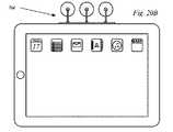
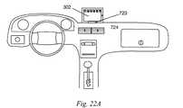
タブレットデバイス302の吊り下げ又は他の方法の搭載に加えて、図22Aに示されるように、搭載アクセサリ720は例えば自動車のダッシュボードにタブレットデバイスを直接に搭載するために用いられうる。1つの実施形態では、搭載アクセサリ720はダッシュボード724に固定されてもよく、タブレットデバイス302に含まれる磁気取り付け特徴部を有効化するために用いられうる。タブレットデバイス302をダッシュボードに機械的に固定することに加えて、搭載アクセサリ720は、タブレットデバイス302に電力を供給し、乗り物内の他の電子デバイスとの接続を提供するなどを行うために用いられうる。例えば、タブレットデバイス302がオーディオデータ及び一部の場合にビデオデータを適切な受信機回路へ無線送信できる。このようにして、メディアデータはタブレットデバイス302から供給されうる。1つの実施形態では、タブレットデバイス302は乗り物に利用可能な他の電子サービスとの連携に用いられうる。例えば、GPSベースナビゲーションがタブレットデバイス302に表示され、交通警告が示され、乗り物情報(ガスレベル、充電レベル等)が示されるなどである。1つの実施形態では、ユーザ入力がタブレットデバイス302に提供されうる。ユーザ入力は乗り物、メディアなどの動作特性を変えるために用いられうる。図22Bはトレッドミル722のようなエクササイズ器具にタブレットデバイス302を搭載するために用いられうる搭載アクセサリ720を示す。 In addition to hanging or otherwise mounting
図23A〜図23Hは様々な周辺デバイス800に磁気で取り付けられたタブレットデバイス302の実施形態を示す。例えば、図23Aはタブレットデバイス302に磁気で取り付けられたカメラ802を示す。カメラ802はタブレットデバイス302に含まれる画像撮像リソースと連動して、又はこれとは別個に動作しうる。図23Bはスタイラス806を有するスタイラスホルダ804を示す。1つの実施形態では、タブレットデバイス302の動作は、スタイラスホルダ804の場合(又は、スタイラス806の存在の場合)にスタイラス認識モードへ変わりうる。スタイラス認識モードでは、タブレットデバイス302の動作は、ディスプレイ808上のスタイラス806の動きが認識され、タブレットデバイス302によって動作されるようなものでありうる。 FIGS. 23A-23H illustrate embodiments of a
図23Cはタブレットデバイス302に磁気で取り付けられたカードスワイプ810を示す。この構成では、ユーザは例えば磁気で符号化されたカードをスワイプでき、タブレットデバイス302による処理のために情報が容易に利用可能になる。図23Dはタブレットデバイス302の補助的なRF送受信に用いられうるアンテナアセンブリ812を示す。 FIG. 23C shows a
図23Eはタブレットデバイス302に追加のメモリリソースを提供するように構成され、タブレットデバイス302に磁気で取り付けられたメモリモジュール814を示す。図23Fはタブレット302に磁気で取り付けられたキーボード816を示す。キーボード816は無線で又は有線接続でタブレットデバイス302と通信できる。 FIG. 23E shows a
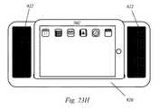
図23Gはタブレットデバイス302に磁気で接続されたゲームコントローラ818を示す。1つの実施形態では、ゲームコントローラ818はタブレットデバイス302に情報を提供できる。情報は、プレイされるゲーム、履歴ゲーム情報、プレーヤ情報及び識別情報などを含みうる。図23Hはタブレットデバイス302により提供されるオーディオコンテンツを広めるためのスピーカ822を有するオーディオ出力モジュール820を示す。 FIG. 23G shows a
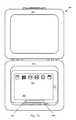
図24はタブレットデバイス902を格納し輸送するために用いられうるトラベルケース900を示す。トラベルケース900はタブレットデバイス902の磁気取り付け特徴部906を有効化するように構成された磁気素子904を含みうる。1つの実施形態では、トラベルケース900はクラムシェル型構成を有し、閉じた形態において、カバー908は、カバー908及びベース910で形成される空洞内にタブレットデバイス902を囲みうる。1つの実施形態では、タブレットデバイス902はタブレットデバイス902を掴んで取り外すことによって手動で解放されうる。1つの実施形態では、トラベルケース900は、磁気素子904とタブレットデバイス902の磁気取り付け特徴部906との間の磁気引力に打ち勝ちうる解放機構を含みうる。1つの実施形態では、解放機構は本質的に機械的でありうる。1つの実施形態では、解放機構は本質的に電気機械的であってもよく、トラベルケース900内の電磁気素子は磁気素子904と磁気取り付け特徴部906との間の磁気引力に打ち勝つようにエネルギーを与えられうる。 FIG. 24 shows a
図25A及び図25Bは物体922の磁気素子920とタブレットデバイス926の形態をとりうる電子デバイスの磁気取り付け特徴部924との間の個別の磁気引力を示す。図25Aに示されるように、磁気素子920は、起電力を与えるために用いられうる少なくとも1つの電磁気素子を含みうる。起電力は磁気素子920と磁気取り付け特徴部922との間の正味磁気引力Fnetに打ち勝つために用いられうる。起電力は、手又は他の機械的機構を用いずに物体922が電子デバイスから分離するようにできる。電磁気素子は遠隔から有効化されてもよいし、電子デバイスを用いて有効化されてもよい。例えば、電子デバイスがタブレットデバイス930の形態をとる場合に、ホームボタン932が押下されてもよく、それによって電磁気素子が有効化し、結果として磁気取り付け特徴部922と磁気素子920との間の磁気引力に打ち勝ち、タブレットデバイス930がトラベルケース900から取り外されることを可能にする。FIGS. 25A and 25B show the individual magnetic attraction between the
図26A〜図26Cは、ホール効果センサのような磁気センサ回路が電子デバイスの動作状態を変えるために用いられうる機構を図示する。特に、図26AはOFF動作状態のタブレットデバイス1000を示す。タブレットデバイス1000はホール効果センサ1002のような磁気センサ回路を含みうる。1つの実施形態では、タブレットデバイス1000はまた、光センサデバイス1004を含みうる。1つの実施形態では、光センサデバイス1004は環境光センサ(ALS)の形態をとりうる。1つの実施形態では、光センサ1004はカメラのような画像撮像デバイスの形態をとりうる。光センサデバイス1004はまた、例えば独立に動作するか共同して動作できる環境光センサとカメラとの両方を含みうるセンサ基板に組み込まれたデバイスの任意の組合せの形態をとりうる。 26A-26C illustrate a mechanism by which a magnetic sensor circuit, such as a Hall effect sensor, can be used to change the operating state of an electronic device. In particular, FIG. 26A shows the
1つの実施形態では、タブレットデバイス1000の動作状態は外部磁界Hによって変えられうる。1つの実施形態では、外部磁界Hは本質的に過渡的であり、外部磁界Hが時間で変わりうるか、及び/又は磁界強度で変わりうることを意味する。1つの状況では、外部磁界Hは磁気リング1006のような磁気素子によって生成され、磁気リング1006は、磁気センサデバイス1002によって過渡的と知覚されるような非過渡的磁界を生成する。例えば、図26A〜図26Cに示されるように、磁気リング1006を左から右へ動かすことによって、ホール効果センサ1002は、外部磁界Hの強度が初期値から始まり、磁気リング1006がホール効果センサ1002に近づくにつれて値が大きくなり、その後磁気リング1006がホール効果センサ1002から遠ざかるように移動するにつれて再び減少するという点で、本質的に過渡的であるとして外部磁界Hを検出できる。磁気リング1006の移動で与えられる過渡的な外部磁界Hの検出の結果として、ホール効果センサ1006がタブレットデバイス1000に信号を提供しうる。信号はタブレットデバイス1000によって解釈され、図26Cに示されるように(OFFのような)現在の動作状態から(ONのような)別の動作状態へ変わりうる。1つの実施形態では、タブレットデバイス1000の状態の変化は、ホール効果センサ1002の近くをリング1006が2回通ることによって、ホール効果センサ1002により与えられる信号がタブレットデバイス1000によって現在の動作状態をONからOFFへ変更するように解釈されうるという点で、本質的にバイナリでありうる。1つの実施形態では、追加の方法でタブレットデバイス1000の動作状態を変えるために用いられうる追加の入力を与えるように、(ALC、環境光センサ又はカメラ1004のような)追加のセンサが連動して(又は単体で)用いられうる。 In one embodiment, the operating state of the
図27A及び図27Bは磁気で結合された物体のハンズフリー取り外しの個別の実施形態を示す。特に、図27Aは第1磁気取り付け特徴部1102が第2磁気取り付け特徴部1104に磁気で取り付けられた磁気取り付け構成1100を示す。1つの実施形態では、第1磁気取り付け特徴部1102は、外部から印加された電圧(又は電流)が利用可能であるかぎり極性P1を有する磁界を生成するために例えば電圧源(又は電流源)1108によって与えられる、外部印加の電圧(又は電流)に応答する素子1106を含みうる。 FIGS. 27A and 27B show individual embodiments of hands-free removal of magnetically coupled objects. In particular, FIG. 27A shows a
1つの実施形態では、電圧又は電流が印加されていない場合に、素子1106は実質的にほとんど又はまったく磁束を提供せず、従って、任意の内在磁界のみに基づいて磁気取り付けを支持できない。1つの実施形態では、第2磁気取り付け特徴部1104は、第1磁気取り付け特徴部1104が第2磁気取り付け特徴部1104の近くに配置された場合に磁気素子1106にアライメントされ磁気素子1106の近くに位置する磁気素子1110を含みうる。1つの実施形態では、磁気素子1110は、図27Bに示されるように外部電流I又は外部電圧Vが印加された場合に、磁気素子1110は素子1106の極性と同じ内在極性P1を有しうる。このようにして、放出力Fejectの形態の正味磁気斥力は、電圧V又は電流Iが利用可能である期間の間に素子1106と磁気素子1110との間に生成されうる。このようにして、サイズ、距離、磁気特性及び電磁気特性を適切に調整することによって、第1磁気取り付け特徴部1102及び第2磁気取り付け特徴部1104は互いに取り外されうる。例えば、磁気取り付け状態1100では、磁気素子1106への電圧V又は電流Iの印加によって、自動的に又は少なくとも手動の取り外しを必要とせずに、第1磁気取り付け特徴部1102及び第2磁気取り付け特徴部1104を分離状態1112に分離させる放出力Fejectが生成されうる。In one embodiment,
図28A及び図28Bは筐体1206の外面1204での磁束漏れBを選択的に制御可能な磁気窓1202を有する第1磁気取り付け特徴部1200を示す。1つの実施形態では、磁気窓1202は磁性流体1210を収容するように構成されたチャネル1208で形成されうる。1つの実施形態では、磁性流体1210は、磁界の存在において強磁性化しうる液体である強磁性流体(ferrofluid)の形態をとりうる。強磁性流体は本質的に、ナノスケールの強磁性体又はフェリ磁性の粒子が媒体液の有機溶媒又は水に浮遊した液体で形成されたコロイドである。各微粒子は凝縮を防ぐために界面活性剤で完全に被覆される。大きな強磁性粒子は同質のコロイド混合物から奪われ、強磁界に晒された場合に磁性粉塵の別個の凝縮を形成しうる。ナノ粒子の磁気引力は、界面活性剤のファンデルワールス斥力が磁気凝縮を十分に妨げるほど弱い。強磁性流体は通常、外部から印加される場がない場合に磁性を維持しない。 28A and 28B illustrate a first
従って、無効状態(すなわち、式(1)が満たされる)において、磁気取り付け特徴部1200は、磁性流体1210が磁気素子1212により生成される磁界と相互作用する筐体1206に組み込まれるかこれの近接近にある磁気素子1212を含みうる。磁気流体1210の磁性は筐体1206の外面1204での任意の漏れ磁束を防ぎ、よって式(1)を満たすために必要な境界条件を与える。このようにして、外面1204での磁気面M1を与えるために、磁気素子1212を移動するための要件が存在しない。1つの実施形態では、磁気窓1202はまた、図28Bに示されるように磁性流体1210を収容するのに十分なボリュームを与える(1つ以上の)容器1214を含みうる。 Thus, in the disabled state (ie, equation (1) is satisfied), the
1つの実施形態では、第2磁気取り付け特徴部1216は磁気素子1212を露出するように磁性流体1210をチャネル1208から1つ又は両方の容器1214に移動させうる機構を含みうる。磁気素子1212を露出することによって、式(2)を満たす磁気面M2が与えられうる。1つの実施形態では、磁性流体1210を移動するために用いられる機構は、磁気素子121の引力に打ち勝つのに十分な強さの磁界強度を有する磁石1218の形態をとりうる。このようにして、第1磁気取り付け特徴部1200の近くに第2磁気取り付け特徴部1216を配置することによって、磁気窓1202が(式(1)に一致する)閉じた状態から(式(2)に一致する)開いた状態に移行されうる。 In one embodiment, the second
図29A及び図29Bは保持磁石1302の形態の保持機構を有する第1磁気取り付け特徴部1300を示す。磁石1302を与えることによって、有益なスペースが維持されうる。磁石1302の強度及びサイズはよく規定されうるので、第2磁気取り付け特徴部1306内の有効化した磁石1304のサイズ及び強度もよく規定されうる。例えば、第1磁気取り付け特徴部を有効化する(すなわち、式(2)を満たす)ために、磁石1308は(磁石1302に磁気で取り付けられた)無効位置X1から有効位置X2へ移動しなければならない。これは、有効化する磁石1304を磁石1308の近くに配置することによって実現されうる。1つの実施形態では、磁石1302と磁石1308との間の磁気引力に打ち勝ち、磁石1308が磁石1302から取り外されて磁石1304の方へ移動し、処理の磁気面M2を生成する(すなわち式(2)を満たす)ように、磁石1304、1308の内在磁力が調整されうる。 FIGS. 29A and 29B show a first
図30A及び図30Bは移動磁石1308及び保持磁石1302を収容するサイズのチャネル1310を有する第1磁気取り付け特徴部1300の実施形態を示す。1つの実施形態では、移動磁石1308とチャネル1310の内面との間の潤滑剤(不図示)の存在に起因して移動磁石1308はチャネル1310内を滑らかにわずかな抵抗で移動できる。 FIGS. 30A and 30B illustrate an embodiment of a first
図31A〜図31Cは取り付け構成に基づく情報を提供するように構成された図30A〜図30Bに示される第1磁気取り付け特徴部1300の別の実施形態を示す。1つの実施形態では、磁石1302のうちのすべて又は少なくとも一部は、筐体1206の金属によって形成されるシャーシ接地から電気的に分離される。1つの実施形態では、磁石1302のうちのすべて又は少なくとも一部は、磁石1308が磁石1032に取り付けられたかを感知するように構成されたセンサ回路に結合されうる。磁石1308が磁石1302に取り付けられたことをセンサ回路が感知する場合に、第1論理値(「0」又は「1」の適切な方)が提供されうる。逆に、磁石1308が磁石1302に取り付けられていないことをセンサ回路が感知する場合に、第1論理値とは異なる第2論理値(「1」又は「0」)が提供されうる。1つの実施形態では、第1論理値及び第2論理値の形態の情報は磁気取り付け状態を識別するために用いられうる。1つの実施形態では、取り付け状態は磁気で取り付けられた物体を識別できる(図32に示される表1を参照)。1つの実施形態では、取り付け状態に対応する取り付け情報は、タブレットデバイス1000のような電子デバイスの動作状態を変えるために用いられうる。例えば、表1で与えられる情報を用いて、センサ回路がスタイラスに対応するデータ{1,0,0,0,0,1}を感知するならば、タブレットデバイス1000は現在の動作状態を、タッチスクリーン又はディスプレイ上のスタイラスを感知することに一致する状態に変えうる。 FIGS. 31A-31C illustrate another embodiment of the first
図32A及び図32Bは図31A〜図31Cに示される第1取り付け特徴部1300の特定の実施形態を示す。1つの実施形態では、保持磁石1302は筐体102から電気的に分離されてもよく、センサ回路への線1322を介して電気的に接続された電気接点1320を含みうる。見て取れるように、保持磁石1302が移動磁石1308に取り付けられていない場合に、センサ回路とシャーシ接地との間に電気経路が存在せず、従って実質的に何も電流が流れず、これは第2論理状態に対応する。他方、図32Bに示されるように、移動磁石1308が保持磁石1302に、より具体的には電気接点1320に接触している場合に、電流経路1326が与えられ、電流Iがシャーシ接地へ/シャーシ接地から流れることを可能にする。図33は個別の動作磁気コード及び動作状態の表を示す。 32A and 32B show a specific embodiment of the
図34は電子デバイスによって利用される機能モジュールの構成1600のブロック図である。電子デバイスは例えばタブレットデバイス1500でありうる。構成1600は、ポータブルメディアデバイスのユーザにメディアを出力できるが、データストレージ1604にデータを格納して読み出すこともできる電子デバイス1602を含む。構成1600はまた、グラフィカルユーザインタフェース(GUI)マネージャ1606を含む。GUIマネージャ1606は、ディスプレイデバイスへ提供されて表示される情報を制御するように動作する。構成1600はまた、ポータブルメディアデバイスとアクセサリデバイスとの間の通信を容易にする通信モジュール1608を含む。さらに、構成1600は、ポータブルメディアデバイスに結合されうるアクセサリデバイスを認証し、これからデータを取得するように動作するアクセサリマネージャ1610を含む。 FIG. 34 is a block diagram of a
図35は記載された実施形態とともに使用するのに適した電子デバイス1650のブロック図である。電子デバイス1650は個別のコンピューティングデバイスの回路を説明する。電子デバイス1650は、電子デバイス1650の動作全体を制御するためのマイクロプロセッサ又はコントローラに関連するプロセッサ1652を含む。電子デバイス1650はメディアアイテムに関連するメディアデータをファイルシステム1654又はキャッシュ1656に格納する。ファイルシステム1654は、典型的に、ストレージディスク又は複数のディスクである。ファイルシステム1654は典型的に、電子デバイス1650に大容量ストレージ能力を提供する。しかしながら、ファイルシステム1654へのアクセス時間は比較的遅いので、電子デバイス1650はまた、キャッシュ1656を含みうる。キャッシュ1656は例えば半導体メモリで与えられるランダムアクセスメモリ(RAM)である。キャッシュ1656への相対アクセス時間はファイルシステム1654よりも実質的に短い。しかしながら、キャッシュ1656はファイルシステム1654の大記憶容量を有しない。さらに、ファイルシステム1654は、起動中に、キャッシュ1656よりも多くの電力を消費する。電子デバイス1650がバッテリ1674により給電されるポータブルメディアデバイスである場合に、電力消費が懸念される場合がある。電子デバイス1650はまた、RAM1670及びリードオンリメモリ(ROM)1672を含みうる。ROM1672は実行されるプログラム、ユーティリティ又はプロセスを不揮発に格納できる。RAM1670はキャッシュ1656のためのような揮発データストレージを提供する。 FIG. 35 is a block diagram of an electronic device 1650 suitable for use with the described embodiments. Electronic device 1650 describes the circuitry of an individual computing device. Electronic device 1650 includes a
電子デバイス1650はまた、電子デバイス1650のユーザが電子デバイス1650と相互作用することを可能にするユーザ入力デバイス1658を含む。例えば、ユーザ入力デバイス1658は、ボタン、キーパッド、ダイアル、タッチスクリーン、オーディオ入力インタフェース、ビジュアル/画像撮像入力インタフェース、センサデータの形態の入力などのような様々な形態をとりうる。さらに、電子デバイス1650はユーザに情報を表示するためにプロセッサ1652によって制御されうるディスプレイ1660(スクリーンディスプレイ)を含む。データバス1666は少なくともファイルシステム1654、キャッシュ1656、プロセッサ1652及びCODEC1663間のデータ転送を容易にしうる。 Electronic device 1650 also includes a
1つの実施形態では、電子デバイス1650はファイルシステム1654に複数のメディアアイテム(例えば、楽曲、ポッドキャスト等)を格納する機能を有する。電子デバイスに特定のメディアアイテムを再生させることをユーザが望む場合に、利用可能なメディアアイテムのリストがディスプレイ1660に表示される。その後、ユーザ入力デバイス1658を用いて、ユーザは利用可能なメディアアイテムのうちの1つを選択できる。プロセッサ1652は、特定のメディアアイテムの選択を受信したことに応じて、特定のメディアアイテムについてのメディアデータ(例えば、オーディオファイル)をコーダ/エンコーダ(CODEC)1663に供給する。CODEC1663はその後、スピーカ1664のためのアナログ出力信号を生成する。スピーカ1664は電子デバイス1650の内部のスピーカであってもよいし、電子デバイス1650の外部のスピーカであってもよい。例えば、電子デバイス1650に接続するヘッドフォン又はイヤフォンは外部スピーカとみなされるだろう。 In one embodiment, the electronic device 1650 has the capability of storing multiple media items (eg, songs, podcasts, etc.) in the
電子デバイス1650はまた、データリンク1662に結合するネットワーク/バスインタフェース1661を含む。データリンク1662は、電子デバイス1650がホストコンピュータ又はアクセサリデバイスに結合することを可能にする。データリンク1662は、有線接続又は無線接続を介して提供されうる。無線接続の場合に、ネットワーク/バスインタフェース1661は無線送受信機を含みうる。メディアアイテム(メディアアセット)は、1つ以上の異なるタイプのメディアコンテンツに関連しうる。1つの実施形態では、メディアアイテムはオーディオトラック(例えば、楽曲、オーディオブック及びポッドキャスト)である。別の実施形態では、メディアアイテムは画像(例えば、写真)である。しかしながら、他の実施形態では、メディアアイテムはオーディオ、グラフィック又は視覚コンテンツの任意の組合せでありうる。センサ1676は任意の回数の刺激を検出するための回路の形態をとりうる。例えば、センサ1676は、外部磁界に応答するホール効果センサ、オーディオセンサ、光度計のような光センサなどを含みうる。 The electronic device 1650 also includes a network /
記載された実施形態の様々な側面、実施形態、実装又は特徴は別個に用いられてもよいし、任意の組合せで用いられてもよい。記載された実施形態の様々な側面は、ソフトウェア、ハードウェア又はハートウェアとソフトウェアとの組み合わせによって実装されうる。記載された実施形態はまた、過渡的でないコンピュータ読取可能な媒体上のコンピュータ読取可能なコードとして実施されうる。コンピュータ読取可能な媒体は、データを格納できる任意のデータストレージデバイスとして規定され、データはその後コンピュータシステムによって読み出されうる。コンピュータ読取可能な媒体の例は、リードオンリメモリ、ランダムアクセスメモリ、CD−ROM、DVD、磁気テープ及び光データストレージデバイスを含む。コンピュータ読取可能な媒体はまた、コンピュータ読取可能なコードが分散して格納され実行されるように、ネットワーク結合されたコンピュータシステムに分散されうる。 Various aspects, embodiments, implementations or features of the described embodiments may be used separately or in any combination. Various aspects of the described embodiments may be implemented by software, hardware or a combination of heartware and software. The described embodiments may also be implemented as computer readable code on a non-transitory computer readable medium. A computer-readable medium is defined as any data storage device that can store data, which can thereafter be read by a computer system. Examples of computer readable media include read only memory, random access memory, CD-ROM, DVD, magnetic tape and optical data storage devices. The computer readable medium can also be distributed over a network coupled computer system so that the computer readable code is stored and executed in a distributed fashion.
上述の記載は、説明を目的として、記載された実施形態の完全な理解を提供するために特定の用語を用いた。しかしながら、記載された実施形態を実施するために特定の詳細が必要とならないことが当業者に明らかであろう。よって、本明細書に記載された特定の実施形態の上述の説明は、説明及び記載の目的で提示される。これらは排他的であることを目的とせず、開示された形態そのものに実施形態を限定することを目的としない。上記の教示の観点から多くの修正及び変形が可能であることが当業者に明らかであろう。 The foregoing description uses specific terminology for the purpose of explanation to provide a thorough understanding of the described embodiments. However, it will be apparent to one skilled in the art that the specific details are not required in order to practice the described embodiments. Thus, the foregoing descriptions of specific embodiments described herein are presented for purposes of explanation and description. They are not intended to be exclusive and are not intended to limit the embodiments to the precise forms disclosed. It will be apparent to those skilled in the art that many modifications and variations are possible in light of the above teaching.
記載された実施形態の利点は多数ある。異なる側面、実施形態又は実装は以下の利点のうちの1つ以上を与えうる。本実施形態の多くの特徴及び利点は明細書から明らかであり、よって、本発明のこのような特徴及び利点のすべてをカバーすることが添付の特許請求の範囲によって意図される。さらに、数多くの修正及び変更が当業者に容易に思いつくので、実施形態は説明され記載された正確な構造及び動作に限定されるべきではない。よって、すべての適切な修正及び均等物が特許請求の範囲に含まれるとみなされる。 The advantages of the described embodiments are numerous. Different aspects, embodiments or implementations may provide one or more of the following advantages. Many features and advantages of this embodiment will be apparent from the description, and thus it is intended by the appended claims to cover all such features and advantages of the invention. Further, since numerous modifications and changes will readily occur to those skilled in the art, the embodiments should not be limited to the precise structure and operation described and described. Accordingly, all suitable modifications and equivalents are considered to be within the scope of the claims.
Claims (10)
Translated fromJapanese第1側と、前記第1側とは反対の第2側とを有する本体と、
前記本体の第1側において、前記第1電子デバイスの対応する磁気取り付け特徴部を磁気取り付けに適さない無効状態から有効化するための第1有効化力を与えるように構成された第1磁石を少なくとも有する第1磁気取り付けシステムと、
前記本体の第2側において、前記第2電子デバイスの対応する磁気取り付け特徴部を前記無効状態から有効化するための第2有効化力を与えるように構成された第2磁石を少なくとも有する第2磁気取り付けシステムとを備え、
前記有効化した第1磁気システム及び前記有効化した第2磁気システムと前記磁気取り付けユニットの対応する磁石との間に生成された磁気取り付け力の結果として、前記個別の第1電子デバイスと前記個別の第2電子デバイスとが共同する電子デバイスとして共に動作可能になることを特徴とする磁気取り付けユニット。A magnetic attachment unit for magnetically attaching at least both an individual first electronic device and an individual second electronic device each having an associated magnetic attachment feature, the magnetically attached electronic device comprising: Communicating with each other when magnetically mounted to form a system, the magnetic mounting unit
A body having a first side and a second side opposite to the first side;
A first magnet configured to provide a first enabling force on a first side of the bodyto enable a corresponding magnetic attachment feature of the first electronic devicefrom an invalid state not suitable for magnetic attachment ; A first magnetic mounting system having at least;
A second magnet having at least a second magnet configured to provide a second enabling force on the second side of the bodyto enable a corresponding magnetic attachment feature of the second electronic devicefrom the disabled state; With a magnetic mounting system,
As a result of the magnetic attachment force generated between the activated first magnetic system and the activated second magnetic system and the corresponding magnet of the magnetic attachment unit, the individual first electronic device and the individual A magnetic mounting unit capable of operating together as an electronic device cooperating with the second electronic device.
前記第1電子デバイスと前記第2電子デバイスとの間の通信チャネルと、処理リソースとを少なくとも与えるように構成された電子回路と、
データを格納するように構成されたデータストレージユニットとを更に有することを特徴とする請求項1又は2に記載の磁気取り付けユニット。The body is
An electronic circuit configured to provide at least a communication channel between the first electronic device and the second electronic device and processing resources;
The magnetic mounting unit according to claim 1, further comprising a data storage unit configured to store data.
前記第1磁気取り付けシステムを組み込む第1部分と、
前記第2磁気取り付けシステムを組み込む第2部分と、
前記第1電子デバイスと前記第2電子デバイスとが可撓性部分に対して互いに独立に旋回するように前記第1部分及び前記第2部分に取り付けられた前記可撓性部分とを更に備えることを特徴とする請求項1に記載の磁気取り付けユニット。The body is
A first part incorporating the first magnetic mounting system;
A second part incorporating the second magnetic mounting system;
The first electronic device and the second electronic device further comprise the flexible portion attached to the first portion and the second portion such that the first electronic device and the second electronic device pivot independently of each other with respect to the flexible portion. The magnetic mounting unit according to claim 1.
Applications Claiming Priority (3)
| Application Number | Priority Date | Filing Date | Title |
|---|---|---|---|
| US201161438220P | 2011-01-31 | 2011-01-31 | |
| US61/438,220 | 2011-01-31 | ||
| PCT/US2012/023025WO2012106215A2 (en) | 2011-01-31 | 2012-01-27 | Magnetic attachment unit |
Related Child Applications (1)
| Application Number | Title | Priority Date | Filing Date |
|---|---|---|---|
| JP2015000495ADivisionJP6097315B2 (en) | 2011-01-31 | 2015-01-05 | Magnetic mounting unit |
Publications (2)
| Publication Number | Publication Date |
|---|---|
| JP2014508998A JP2014508998A (en) | 2014-04-10 |
| JP5678214B2true JP5678214B2 (en) | 2015-02-25 |
Family
ID=45615068
Family Applications (6)
| Application Number | Title | Priority Date | Filing Date |
|---|---|---|---|
| JP2013551997AActiveJP5745097B2 (en) | 2011-01-31 | 2012-01-13 | Cover attachment with flexible display |
| JP2013551395AExpired - Fee RelatedJP5678214B2 (en) | 2011-01-31 | 2012-01-27 | Magnetic mounting unit |
| JP2015000495AActiveJP6097315B2 (en) | 2011-01-31 | 2015-01-05 | Magnetic mounting unit |
| JP2015093467AActiveJP5960872B2 (en) | 2011-01-31 | 2015-04-30 | Cover attachment with flexible display |
| JP2016124781AActiveJP6407206B2 (en) | 2011-01-31 | 2016-06-23 | Cover attachment with flexible display |
| JP2018138551APendingJP2018190448A (en) | 2011-01-31 | 2018-07-24 | Cover attachment with flexible display |
Family Applications Before (1)
| Application Number | Title | Priority Date | Filing Date |
|---|---|---|---|
| JP2013551997AActiveJP5745097B2 (en) | 2011-01-31 | 2012-01-13 | Cover attachment with flexible display |
Family Applications After (4)
| Application Number | Title | Priority Date | Filing Date |
|---|---|---|---|
| JP2015000495AActiveJP6097315B2 (en) | 2011-01-31 | 2015-01-05 | Magnetic mounting unit |
| JP2015093467AActiveJP5960872B2 (en) | 2011-01-31 | 2015-04-30 | Cover attachment with flexible display |
| JP2016124781AActiveJP6407206B2 (en) | 2011-01-31 | 2016-06-23 | Cover attachment with flexible display |
| JP2018138551APendingJP2018190448A (en) | 2011-01-31 | 2018-07-24 | Cover attachment with flexible display |
Country Status (10)
| Country | Link |
|---|---|
| US (7) | US9335793B2 (en) |
| EP (4) | EP2671133B1 (en) |
| JP (6) | JP5745097B2 (en) |
| KR (6) | KR101868721B1 (en) |
| CN (7) | CN102622052B (en) |
| AU (3) | AU2012212597B2 (en) |
| BR (2) | BR112013019205B1 (en) |
| MX (2) | MX2013008811A (en) |
| TW (4) | TWI587120B (en) |
| WO (2) | WO2012106092A1 (en) |
Families Citing this family (690)
| Publication number | Priority date | Publication date | Assignee | Title |
|---|---|---|---|---|
| US7920129B2 (en) | 2007-01-03 | 2011-04-05 | Apple Inc. | Double-sided touch-sensitive panel with shield and drive combined layer |
| US9370640B2 (en) | 2007-09-12 | 2016-06-21 | Novasentis, Inc. | Steerable medical guide wire device |
| US9013367B2 (en) | 2008-01-04 | 2015-04-21 | Nanolumens Acquisition Inc. | Flexible display |
| US9071809B2 (en) | 2008-01-04 | 2015-06-30 | Nanolumens Acquisition, Inc. | Mobile, personsize display system and method of use |
| US9655267B2 (en) | 2008-01-04 | 2017-05-16 | Nanolumens Acquisition, Inc. | Retractable display system and method of use |
| US9330589B2 (en) | 2011-11-16 | 2016-05-03 | Nanolumens Acquisition, Inc. | Systems for facilitating virtual presence |
| US8602875B2 (en) | 2009-10-17 | 2013-12-10 | Nguyen Gaming Llc | Preserving game state data for asynchronous persistent group bonus games |
| US9626826B2 (en) | 2010-06-10 | 2017-04-18 | Nguyen Gaming Llc | Location-based real-time casino data |
| US11990005B2 (en) | 2009-11-12 | 2024-05-21 | Aristocrat Technologies, Inc. (ATI) | Gaming system supporting data distribution to gaming devices |
| US8864586B2 (en) | 2009-11-12 | 2014-10-21 | Nguyen Gaming Llc | Gaming systems including viral gaming events |
| US8597108B2 (en) | 2009-11-16 | 2013-12-03 | Nguyen Gaming Llc | Asynchronous persistent group bonus game |
| US8467179B2 (en) | 2010-01-28 | 2013-06-18 | Cruxcase, Llc | Tablet computer case and associated methods |
| US8696470B2 (en) | 2010-04-09 | 2014-04-15 | Nguyen Gaming Llc | Spontaneous player preferences |
| US8947415B1 (en)* | 2010-04-19 | 2015-02-03 | Green Display LLC | Display system and method |
| US20120106103A1 (en)* | 2010-06-23 | 2012-05-03 | Tanios Nohra | Radio frequency energy harvesting enclosure for radio frequency connected devices |
| USD658187S1 (en) | 2011-03-17 | 2012-04-24 | Incase Designs Corp. | Foldable front cover for electronic tablet |
| USD658188S1 (en)* | 2011-03-17 | 2012-04-24 | Incase Designs Corp. | Foldable front cover for electronic tablet |
| USD679715S1 (en)* | 2010-09-17 | 2013-04-09 | Apple Inc. | Packaging |
| USD663304S1 (en)* | 2010-09-17 | 2012-07-10 | Apple Inc. | Cover |
| US8344836B2 (en) | 2010-09-17 | 2013-01-01 | Apple Inc. | Protective cover for a tablet computer |
| USD688669S1 (en)* | 2010-09-17 | 2013-08-27 | Apple Inc. | Cover and packaging therefor |
| USD671114S1 (en)* | 2011-02-25 | 2012-11-20 | Apple Inc. | Portable display device with cover |
| US9486704B2 (en) | 2010-11-14 | 2016-11-08 | Nguyen Gaming Llc | Social gaming |
| US12100260B2 (en) | 2010-11-14 | 2024-09-24 | Aristocrat Technologies, Inc. (ATI) | Multi-functional peripheral device |
| US9235952B2 (en) | 2010-11-14 | 2016-01-12 | Nguyen Gaming Llc | Peripheral management device for virtual game interaction |
| US9564018B2 (en) | 2010-11-14 | 2017-02-07 | Nguyen Gaming Llc | Temporary grant of real-time bonus feature |
| US10052551B2 (en) | 2010-11-14 | 2018-08-21 | Nguyen Gaming Llc | Multi-functional peripheral device |
| US9595161B2 (en) | 2010-11-14 | 2017-03-14 | Nguyen Gaming Llc | Social gaming |
| US8612874B2 (en) | 2010-12-23 | 2013-12-17 | Microsoft Corporation | Presenting an application change through a tile |
| US8689123B2 (en) | 2010-12-23 | 2014-04-01 | Microsoft Corporation | Application reporting in an application-selectable user interface |
| US9335793B2 (en) | 2011-01-31 | 2016-05-10 | Apple Inc. | Cover attachment with flexible display |
| US9201185B2 (en) | 2011-02-04 | 2015-12-01 | Microsoft Technology Licensing, Llc | Directional backlighting for display panels |
| USD677658S1 (en) | 2011-03-02 | 2013-03-12 | Apple Inc. | Portable display device |
| US8572830B2 (en)* | 2011-03-14 | 2013-11-05 | Apple Inc. | Method and apparatus for producing magnetic attachment system |
| US9494975B1 (en)* | 2011-03-28 | 2016-11-15 | Amazon Technologies, Inc. | Accessory device identification method |
| ITMI20110127U1 (en)* | 2011-04-14 | 2012-10-15 | Tucano S R L | HOUSING FOR A TABLET ELECTRONIC DEVICE, IN PARTICULAR A COMPUTER TABLET |
| USD691611S1 (en)* | 2011-04-21 | 2013-10-15 | Volkswagen Aktiengesellschaft | Tablet computer case |
| TWD145638S (en)* | 2011-05-27 | 2012-03-01 | 達方電子股份有限公司 | Casing with foldable keyboard |
| US9104307B2 (en) | 2011-05-27 | 2015-08-11 | Microsoft Technology Licensing, Llc | Multi-application environment |
| USD683731S1 (en)* | 2011-05-31 | 2013-06-04 | Compal Electronics, Inc. | Tablet computer combined with cover with keyboard |
| USD674800S1 (en)* | 2011-06-10 | 2013-01-22 | Samsung Electronics Co., Ltd. | Mobile terminal case |
| USD674799S1 (en)* | 2011-06-10 | 2013-01-22 | Samsung Electronics Co., Ltd. | Mobile terminal case |
| TWI446376B (en)* | 2011-07-15 | 2014-07-21 | Wistron Corp | Transformer device having the function of a mouse pad and a combination thereof |
| US8605421B2 (en)* | 2011-08-17 | 2013-12-10 | Creator Technology B.V. | Display device with flexible display |
| USD675625S1 (en)* | 2011-08-22 | 2013-02-05 | Mophie, Inc. | Tablet computer keyboard-case |
| US20130050164A1 (en)* | 2011-08-23 | 2013-02-28 | Nicholaus R. Rericha | Electronic device cases and covers having a reflective display, and methods thereof |
| US8824166B2 (en) | 2011-08-31 | 2014-09-02 | Apple Inc. | Magnetic stand for tablet device |
| US20130057587A1 (en) | 2011-09-01 | 2013-03-07 | Microsoft Corporation | Arranging tiles |
| JP5392863B2 (en) | 2011-09-05 | 2014-01-22 | 任天堂株式会社 | Peripheral device, information processing system, and connection method of peripheral device |
| US9146670B2 (en) | 2011-09-10 | 2015-09-29 | Microsoft Technology Licensing, Llc | Progressively indicating new content in an application-selectable user interface |
| US20130241381A1 (en)* | 2011-09-20 | 2013-09-19 | Speculative Product Design, Llc | One-piece case for enclosing a tablet-computing device |
| US8963895B2 (en) | 2011-09-22 | 2015-02-24 | Nano Lumens Acquisition Inc. | Ubiquitously mountable image display system |
| USD685801S1 (en)* | 2011-09-27 | 2013-07-09 | Amazon Technologies, Inc. | Electronic device cover |
| USD685799S1 (en)* | 2011-09-27 | 2013-07-09 | Amazon Technologies, Inc. | Electronic device cover |
| USD685802S1 (en)* | 2011-09-27 | 2013-07-09 | Wilfrido Loor Canizares | Lighted electronic device cover |
| US9182935B2 (en) | 2011-09-27 | 2015-11-10 | Z124 | Secondary single screen mode activation through menu option |
| USD685800S1 (en)* | 2011-09-27 | 2013-07-09 | Amazon Technologies, Inc. | Lighted electronic device cover |
| US9729685B2 (en) | 2011-09-28 | 2017-08-08 | Apple Inc. | Cover for a tablet device |
| US9630096B2 (en) | 2011-10-03 | 2017-04-25 | Nguyen Gaming Llc | Control of mobile game play on a mobile vessel |
| US9672686B2 (en) | 2011-10-03 | 2017-06-06 | Nguyen Gaming Llc | Electronic fund transfer for mobile gaming |
| US20130088410A1 (en)* | 2011-10-07 | 2013-04-11 | Research In Motion Limited | Notification device |
| USD682839S1 (en)* | 2011-10-07 | 2013-05-21 | Mezzo Movies Limited | Holder for a computer |
| US8766921B2 (en)* | 2011-10-11 | 2014-07-01 | Nokia Corporation | Apparatus cover with keyboard |
| US8797132B2 (en)* | 2011-10-18 | 2014-08-05 | Belkin International, Inc. | Accessory for a mobile electronic device and method of providing and using the same |
| USD679277S1 (en)* | 2011-10-27 | 2013-04-02 | Cruxcase, Llc | Tablet computer case |
| US8872792B2 (en)* | 2011-10-28 | 2014-10-28 | Atmel Corporation | Active stylus with energy harvesting |
| USD676449S1 (en)* | 2011-10-28 | 2013-02-19 | Cruxcase, Llc | Tablet computer case |
| KR101531524B1 (en) | 2011-10-31 | 2015-06-25 | 엘지전자 주식회사 | Portable keyboard |
| US9227763B2 (en)* | 2011-11-09 | 2016-01-05 | Zagg Intellectual Property Holding Co., Inc. | Multi-functional protective cover for a computing accessory and support accessory for a portable electronic device, and methods and systems relating thereto |
| KR20130056674A (en)* | 2011-11-22 | 2013-05-30 | 삼성전자주식회사 | Flexible display apparatus and method for providing user interface by using the same |
| USD675626S1 (en)* | 2011-12-05 | 2013-02-05 | Inmusic Brands, Inc. | Case for a tablet computer |
| USD676050S1 (en)* | 2011-12-06 | 2013-02-12 | Tumi, Inc. | Computer tablet stand |
| USD694245S1 (en)* | 2011-12-06 | 2013-11-26 | Tumi, Inc. | Computer tablet stand |
| TW201325373A (en)* | 2011-12-09 | 2013-06-16 | Acer Inc | Protective cover with support function |
| TWD149642S (en)* | 2011-12-13 | 2012-10-11 | 宏碁股份有限公司 | Tablet computer |
| USD679279S1 (en)* | 2011-12-19 | 2013-04-02 | Chi Mei Communication Systems, Inc. | Protecting case for portable electronic device |
| KR101850818B1 (en)* | 2012-01-03 | 2018-04-23 | 삼성전자주식회사 | Mobile apparatus |
| KR20130080937A (en)* | 2012-01-06 | 2013-07-16 | 삼성전자주식회사 | Apparatus and method for dislplaying a screen of portable device having a flexible display |
| US9141136B2 (en)* | 2012-01-08 | 2015-09-22 | Parle Innovation, Inc. | Tablet computer carrying case with retractable latch |
| USD682837S1 (en)* | 2012-01-09 | 2013-05-21 | Samsung Electronics Co., Ltd. | Case for a slate computer |
| US9071906B2 (en) | 2012-01-09 | 2015-06-30 | Imation Corp. | Wireless audio player and speaker system |
| JP2015510309A (en)* | 2012-01-09 | 2015-04-02 | イメイション・コーポレイションImation Corp. | Wireless audio player / speaker system |
| US9095061B2 (en)* | 2012-01-09 | 2015-07-28 | Isaiah Coberly | Articulating panel |
| USD734127S1 (en)* | 2012-01-16 | 2015-07-14 | Niva | Fastening device for sampler |
| US8610663B2 (en) | 2012-02-06 | 2013-12-17 | Lg Electronics Inc. | Portable device and method for controlling the same |
| US9052414B2 (en) | 2012-02-07 | 2015-06-09 | Microsoft Technology Licensing, Llc | Virtual image device |
| CN103246315B (en)* | 2012-02-07 | 2018-03-27 | 联想(北京)有限公司 | Electronic equipment and its display methods with a variety of display forms |
| US9354748B2 (en) | 2012-02-13 | 2016-05-31 | Microsoft Technology Licensing, Llc | Optical stylus interaction |
| USD690702S1 (en)* | 2012-02-15 | 2013-10-01 | Samsung Electronics Co., Ltd. | Case for tablet PC |
| US8724300B2 (en)* | 2012-02-24 | 2014-05-13 | Blackberry Limited | Mechanically attached folding cover |
| USD696256S1 (en)* | 2012-02-27 | 2013-12-24 | Marware Inc. | E-book reader case |
| US8749529B2 (en) | 2012-03-01 | 2014-06-10 | Microsoft Corporation | Sensor-in-pixel display system with near infrared filter |
| US8873227B2 (en) | 2012-03-02 | 2014-10-28 | Microsoft Corporation | Flexible hinge support layer |
| US9064654B2 (en) | 2012-03-02 | 2015-06-23 | Microsoft Technology Licensing, Llc | Method of manufacturing an input device |
| US9870066B2 (en)* | 2012-03-02 | 2018-01-16 | Microsoft Technology Licensing, Llc | Method of manufacturing an input device |
| US9426905B2 (en) | 2012-03-02 | 2016-08-23 | Microsoft Technology Licensing, Llc | Connection device for computing devices |
| US9075566B2 (en) | 2012-03-02 | 2015-07-07 | Microsoft Technoogy Licensing, LLC | Flexible hinge spine |
| US9360893B2 (en)* | 2012-03-02 | 2016-06-07 | Microsoft Technology Licensing, Llc | Input device writing surface |
| USRE48963E1 (en) | 2012-03-02 | 2022-03-08 | Microsoft Technology Licensing, Llc | Connection device for computing devices |
| US9460029B2 (en) | 2012-03-02 | 2016-10-04 | Microsoft Technology Licensing, Llc | Pressure sensitive keys |
| US9298236B2 (en) | 2012-03-02 | 2016-03-29 | Microsoft Technology Licensing, Llc | Multi-stage power adapter configured to provide a first power level upon initial connection of the power adapter to the host device and a second power level thereafter upon notification from the host device to the power adapter |
| EP2636331A1 (en)* | 2012-03-05 | 2013-09-11 | Alfred Baron | Fold-down protective cover for electronic devices with a folding cover as base |
| USD713402S1 (en) | 2012-03-06 | 2014-09-16 | Apple Inc. | Portable display device with case |
| USD685803S1 (en) | 2012-03-06 | 2013-07-09 | Apple Inc. | Case |
| USD696253S1 (en)* | 2012-03-06 | 2013-12-24 | Apple Inc. | Portable display device with case |
| KR20130104037A (en)* | 2012-03-12 | 2013-09-25 | 삼성전자주식회사 | Display apparatus and control methodthereof |
| JP5900050B2 (en)* | 2012-03-14 | 2016-04-06 | 富士ゼロックス株式会社 | Information processing apparatus, information processing system, and program |
| CN103365341B (en)* | 2012-03-27 | 2017-05-24 | 联想(北京)有限公司 | Electronic equipment adjusting method and electronic equipment |
| US20130258586A1 (en) | 2012-04-02 | 2013-10-03 | Aevoe International Ltd. | Protective apparatus for tablet electronic device |
| USD693821S1 (en)* | 2012-04-11 | 2013-11-19 | Logitech Europe S.A. | Protective cover for a tablet computer |
| USD716311S1 (en)* | 2012-04-11 | 2014-10-28 | Logitech Europe S.A. | Protective cover for a tablet computer |
| USD678294S1 (en)* | 2012-04-13 | 2013-03-19 | 3M Innovative Properties Company | Case for a tablet electronic device |
| US20130278566A1 (en)* | 2012-04-18 | 2013-10-24 | Research In Motion Limited | Cover for Actuating a Mobile Electronic Device Sensor |
| US9300347B1 (en) | 2012-04-18 | 2016-03-29 | Star Co Scientific Technologies Advanced Research Co, Llc | Active cover for electronic device |
| WO2013158110A1 (en)* | 2012-04-20 | 2013-10-24 | Intel Corporation | Hybrid computing device, apparatus and system |
| US9465520B2 (en) | 2012-05-01 | 2016-10-11 | Jorge Mestre | Messaging device |
| USD686628S1 (en)* | 2012-05-02 | 2013-07-23 | John A. Hall | Electronics device holder |
| TWM479586U (en) | 2012-05-04 | 2014-06-01 | Ezero Technologies Llc | Bracket for a portable device having a near field communication capability and an antenna, and a bracket for a portable device having a near field communication capability and an antenna and a keyboard adapted for near field communication |
| USD672781S1 (en)* | 2012-05-08 | 2012-12-18 | Ning Lu | Y-shaped foldable stand back cover |
| US20130300590A1 (en) | 2012-05-14 | 2013-11-14 | Paul Henry Dietz | Audio Feedback |
| USD672353S1 (en)* | 2012-05-15 | 2012-12-11 | Min Liu | Protective case for a tablet computer |
| USD678882S1 (en) | 2012-05-16 | 2013-03-26 | Microsoft Corporation | Input device with coupling |
| USD678272S1 (en) | 2012-05-16 | 2013-03-19 | Microsoft Corporation | Electronic tablet with input device |
| USD678877S1 (en) | 2012-05-16 | 2013-03-26 | Microsoft Corporation | Electronic tablet |
| USD678880S1 (en) | 2012-05-16 | 2013-03-26 | Microsoft Corporation | Electronic tablet with input device coupling |
| USD677660S1 (en) | 2012-05-16 | 2013-03-12 | Microsoft Corporation | Electronic tablet |
| USD678277S1 (en) | 2012-05-16 | 2013-03-19 | Microsoft Corporation | Input device for an electronic tablet |
| USD678881S1 (en) | 2012-05-16 | 2013-03-26 | Microsoft Corporation | Input device with coupling |
| USD678300S1 (en) | 2012-05-16 | 2013-03-19 | Microsoft Corporation | Input device for an electronic tablet |
| USD690305S1 (en)* | 2012-05-22 | 2013-09-24 | Feng Wen | Tablet cover |
| USD692434S1 (en)* | 2012-05-30 | 2013-10-29 | Samsung Electronics Co., Ltd. | Case for tablet PC |
| US10031556B2 (en)* | 2012-06-08 | 2018-07-24 | Microsoft Technology Licensing, Llc | User experience adaptation |
| US8847979B2 (en)* | 2012-06-08 | 2014-09-30 | Samuel G. Smith | Peek mode and graphical user interface (GUI) experience |
| US8947353B2 (en) | 2012-06-12 | 2015-02-03 | Microsoft Corporation | Photosensor array gesture detection |
| US9019615B2 (en) | 2012-06-12 | 2015-04-28 | Microsoft Technology Licensing, Llc | Wide field-of-view virtual image projector |
| US9459160B2 (en) | 2012-06-13 | 2016-10-04 | Microsoft Technology Licensing, Llc | Input device sensor configuration |
| US9073123B2 (en) | 2012-06-13 | 2015-07-07 | Microsoft Technology Licensing, Llc | Housing vents |
| US20130342464A1 (en)* | 2012-06-13 | 2013-12-26 | Microsoft Corporation | Input Device with Interchangeable Surface |
| US9684382B2 (en) | 2012-06-13 | 2017-06-20 | Microsoft Technology Licensing, Llc | Input device configuration having capacitive and pressure sensors |
| US20130335925A1 (en)* | 2012-06-13 | 2013-12-19 | Acer Incorporated | Portable electronic device |
| US20130335330A1 (en)* | 2012-06-13 | 2013-12-19 | Microsoft Corporation | Media processing input device |
| US9256089B2 (en) | 2012-06-15 | 2016-02-09 | Microsoft Technology Licensing, Llc | Object-detecting backlight unit |
| US9705068B2 (en) | 2012-06-19 | 2017-07-11 | Novasentis, Inc. | Ultra-thin inertial actuator |
| USD714790S1 (en) | 2012-06-22 | 2014-10-07 | Nlu Products, L.L.C. | Tablet computer case |
| USD726730S1 (en)* | 2012-07-12 | 2015-04-14 | Tahir Mahmood | Touch-pad computer carrying case |
| US9355345B2 (en) | 2012-07-23 | 2016-05-31 | Microsoft Technology Licensing, Llc | Transparent tags with encoded data |
| JP5975273B2 (en) | 2012-07-24 | 2016-08-23 | カシオ計算機株式会社 | cover |
| JP5896149B2 (en)* | 2012-07-24 | 2016-03-30 | カシオ計算機株式会社 | cover |
| US9325203B2 (en) | 2012-07-24 | 2016-04-26 | Binh Nguyen | Optimized power consumption in a gaming device |
| JP5915434B2 (en)* | 2012-07-26 | 2016-05-11 | カシオ計算機株式会社 | cover |
| US9489015B2 (en)* | 2012-07-31 | 2016-11-08 | Hewlett-Packard Development Company, L.P. | Cover for a tablet computing device having retaining mechanisms |
| US9183710B2 (en) | 2012-08-03 | 2015-11-10 | Novasentis, Inc. | Localized multimodal electromechanical polymer transducers |
| US9326576B2 (en) | 2012-08-08 | 2016-05-03 | Apple Inc. | Cover for an electronic device |
| GB2504944A (en)* | 2012-08-13 | 2014-02-19 | Plastic Logic Ltd | Wrapable flexible display for attaching to a smartphone etc. with control of display contents following display form. |
| USD707229S1 (en)* | 2012-08-15 | 2014-06-17 | Restoration Hardware, Inc. | Electronic device cover |
| USD706783S1 (en)* | 2012-08-15 | 2014-06-10 | Restoration Hardware, Inc. | Electronic device cover |
| USD714791S1 (en)* | 2012-08-16 | 2014-10-07 | Wellfine Sillicone Products Co. | Protecting case for tablet PC |
| US8964379B2 (en) | 2012-08-20 | 2015-02-24 | Microsoft Corporation | Switchable magnetic lock |
| USD710858S1 (en) | 2012-08-20 | 2014-08-12 | Amazon Technologies, Inc. | Electronic device case |
| USD710857S1 (en) | 2012-08-20 | 2014-08-12 | Amazon Technologies, Inc. | Electronic device cover |
| US9007157B2 (en) | 2012-08-28 | 2015-04-14 | Apple Inc. | Magnetic assembly |
| USD691144S1 (en)* | 2012-08-28 | 2013-10-08 | K&B Sales, Inc. | Tablet computer case |
| GB2505458B (en)* | 2012-08-30 | 2015-01-14 | Draeger Safety Uk Ltd | Mounting assembly |
| CN103677726B (en) | 2012-09-02 | 2017-03-01 | 元太科技工业股份有限公司 | Double-screen electronic device and detachable display module thereof |
| USD706270S1 (en) | 2012-09-07 | 2014-06-03 | Apple Inc. | Cover |
| USD713847S1 (en)* | 2012-09-09 | 2014-09-23 | Fu-Hsiang Chang | Mobile device case |
| USD680530S1 (en) | 2012-09-10 | 2013-04-23 | Microsoft Corporation | Electronic tablet |
| USD689056S1 (en)* | 2012-09-11 | 2013-09-03 | Jianhui Li | Protective casing for PDA, tablet PC, IPAD and the like |
| USD687438S1 (en)* | 2012-09-11 | 2013-08-06 | Ning Lu | Y-shaped tablet computer back cover |
| JP5890072B2 (en)* | 2012-09-12 | 2016-03-22 | アップル インコーポレイテッド | Detection system and method between accessory and electronic device |
| US9086844B2 (en) | 2012-09-12 | 2015-07-21 | International Business Machines Corporation | Invoking a user environment based on device cover |
| CN104769531A (en)* | 2012-09-14 | 2015-07-08 | 尤尼皮克塞尔显示器有限公司 | Foldable multi-touch surface |
| US10176666B2 (en) | 2012-10-01 | 2019-01-08 | Nguyen Gaming Llc | Viral benefit distribution using mobile devices |
| US9152173B2 (en) | 2012-10-09 | 2015-10-06 | Microsoft Technology Licensing, Llc | Transparent display device |
| CN103729026B (en)* | 2012-10-16 | 2017-09-01 | 华硕电脑股份有限公司 | protection cap |
| US8654030B1 (en) | 2012-10-16 | 2014-02-18 | Microsoft Corporation | Antenna placement |
| WO2014059625A1 (en) | 2012-10-17 | 2014-04-24 | Microsoft Corporation | Metal alloy injection molding overflows |
| EP2908970B1 (en) | 2012-10-17 | 2018-01-03 | Microsoft Technology Licensing, LLC | Metal alloy injection molding protrusions |
| WO2014059618A1 (en) | 2012-10-17 | 2014-04-24 | Microsoft Corporation | Graphic formation via material ablation |
| TWD155237S (en)* | 2012-10-22 | 2013-08-11 | 宏碁股份有限公司 | Protective cover |
| US8952892B2 (en) | 2012-11-01 | 2015-02-10 | Microsoft Corporation | Input location correction tables for input panels |
| US8786767B2 (en) | 2012-11-02 | 2014-07-22 | Microsoft Corporation | Rapid synchronized lighting and shuttering |
| EP2915416A4 (en)* | 2012-11-05 | 2016-11-02 | Gui Global Products Ltd | DEVICES AND ACCESSORIES USING AN ACTIVE HINGE |
| USD694246S1 (en)* | 2012-11-05 | 2013-11-26 | Samsung Electronics Co., Ltd. | Case for portable computer |
| CN103809669A (en)* | 2012-11-09 | 2014-05-21 | 辉达公司 | Rear cover for flat plate electronic equipment and flat plate electronic equipment with same |
| USD700611S1 (en)* | 2012-11-14 | 2014-03-04 | Samsonite Ip Holdings S.A R.L. | Case |
| USD700184S1 (en)* | 2012-11-14 | 2014-02-25 | Samsonite Ip Holdings S.A R.L. | Case |
| USD695296S1 (en)* | 2012-11-20 | 2013-12-10 | Fu-Yi Hsu | Protective cover for display |
| US9357312B2 (en) | 2012-11-21 | 2016-05-31 | Novasentis, Inc. | System of audio speakers implemented using EMP actuators |
| US9170650B2 (en) | 2012-11-21 | 2015-10-27 | Novasentis, Inc. | EMP actuators for deformable surface and keyboard application |
| WO2014080545A1 (en)* | 2012-11-22 | 2014-05-30 | Necカシオモバイルコミュニケーションズ株式会社 | Portable terminal apparatus, portable terminal, and portable terminal cover |
| US9348365B2 (en) | 2012-11-22 | 2016-05-24 | John Archie Gillis | Modular computer units |
| US8964364B2 (en)* | 2012-11-23 | 2015-02-24 | Blackberry Limited | Carrying case for controlling a mobile device |
| US9104371B2 (en)* | 2012-12-07 | 2015-08-11 | Apple Inc. | Integrated visual notification system in an accessory device |
| USD730853S1 (en)* | 2012-12-12 | 2015-06-02 | Samsung Electronics Co., Ltd. | Monitor |
| US9513748B2 (en) | 2012-12-13 | 2016-12-06 | Microsoft Technology Licensing, Llc | Combined display panel circuit |
| USD705227S1 (en) | 2012-12-14 | 2014-05-20 | Microsoft Corporation | Input device for an electronic tablet |
| RU2644587C2 (en)* | 2012-12-21 | 2018-02-13 | Конинклейке Филипс Н.В. | Electronic devices, system and method of one of electronic devices control |
| FR3000574A1 (en)* | 2012-12-27 | 2014-07-04 | Jean-Louis Lasseri | Binding accessory for binding two digital tablets, has connection unit whose width is equal to distance between magnetized areas of digital tablets when digital tablets are in face-to-face contact with magnetized areas on same side |
| USD735717S1 (en) | 2012-12-29 | 2015-08-04 | Intel Corporation | Electronic display device |
| CN103914098A (en)* | 2013-01-03 | 2014-07-09 | 鸿富锦精密工业(深圳)有限公司 | All-in-one machine device |
| JP5957619B2 (en)* | 2013-01-04 | 2016-07-27 | ノキア テクノロジーズ オーユー | Device shape change sensing method and apparatus |
| US10088936B2 (en)* | 2013-01-07 | 2018-10-02 | Novasentis, Inc. | Thin profile user interface device and method providing localized haptic response |
| WO2014107677A1 (en) | 2013-01-07 | 2014-07-10 | Novasentis, Inc. | Method and localized haptic response system provided on an interior-facing surface of a housing of an electronic device |
| KR102060155B1 (en)* | 2013-01-11 | 2019-12-27 | 삼성전자주식회사 | Method and apparatus for controlling multi-tasking in electronic device using double-sided display |
| KR102051908B1 (en) | 2013-01-16 | 2019-12-04 | 삼성전자주식회사 | Mobile apparatus and method for displaying information |
| KR102060153B1 (en)* | 2013-01-24 | 2020-01-09 | 삼성전자주식회사 | A cover,an electronic device using the same and operating method thereof |
| CN104969140B (en) | 2013-01-31 | 2019-01-04 | 惠普发展公司,有限责任合伙企业 | Display Mounting System |
| US9110840B2 (en)* | 2013-01-31 | 2015-08-18 | Hewlett-Packard Development Company, L.P. | Base for a tablet computer |
| KR102097361B1 (en) | 2013-02-01 | 2020-04-07 | 삼성디스플레이 주식회사 | Mobile device having a flexible display device and method of operating the same |
| US9176538B2 (en)* | 2013-02-05 | 2015-11-03 | Microsoft Technology Licensing, Llc | Input device configurations |
| US12399526B2 (en) | 2013-02-14 | 2025-08-26 | Viteds, Llc | Foldable portable electronic device |
| US10578499B2 (en) | 2013-02-17 | 2020-03-03 | Microsoft Technology Licensing, Llc | Piezo-actuated virtual buttons for touch surfaces |
| USD722057S1 (en)* | 2013-02-18 | 2015-02-03 | Clamcase, Llc | Tablet device case |
| USD722602S1 (en)* | 2013-02-18 | 2015-02-17 | Clamcase, Llc | Tablet device case |
| TWI502320B (en)* | 2013-02-27 | 2015-10-01 | Wistron Corp | Electronic apparatus |
| US9638835B2 (en) | 2013-03-05 | 2017-05-02 | Microsoft Technology Licensing, Llc | Asymmetric aberration correcting lens |
| US20140253024A1 (en)* | 2013-03-06 | 2014-09-11 | Nokia Corporation | Method and apparatus for wirelessly charging mobile devices |
| US9128671B2 (en)* | 2013-03-07 | 2015-09-08 | Hewlett-Packard Development Company, L.P. | Docking device |
| US9377807B2 (en) | 2013-03-08 | 2016-06-28 | Blackberry Limited | Magnetic connector |
| EP2775692B1 (en)* | 2013-03-08 | 2017-02-08 | BlackBerry Limited | Magnetic connector |
| KR102241291B1 (en)* | 2013-03-14 | 2021-04-16 | 삼성전자주식회사 | An electronic device and operating method thereof |
| US11030851B2 (en) | 2013-03-15 | 2021-06-08 | Nguyen Gaming Llc | Method and system for localized mobile gaming |
| US10421010B2 (en) | 2013-03-15 | 2019-09-24 | Nguyen Gaming Llc | Determination of advertisement based on player physiology |
| US12347268B2 (en) | 2013-03-15 | 2025-07-01 | Aristocrat Technologies, Inc. | Adaptive mobile device gaming system |
| US9814970B2 (en) | 2013-03-15 | 2017-11-14 | Nguyen Gaming Llc | Authentication of mobile servers |
| US9576425B2 (en) | 2013-03-15 | 2017-02-21 | Nguyen Gaming Llc | Portable intermediary trusted device |
| US9600976B2 (en) | 2013-03-15 | 2017-03-21 | Nguyen Gaming Llc | Adaptive mobile device gaming system |
| US12347267B2 (en) | 2013-03-15 | 2025-07-01 | Aristocrat Technologies, Inc. | Game management for mobile and remote gaming devices |
| CN103209232B (en)* | 2013-03-27 | 2015-10-28 | 广东威创视讯科技股份有限公司 | A kind of spliced mobile device |
| US9304549B2 (en) | 2013-03-28 | 2016-04-05 | Microsoft Technology Licensing, Llc | Hinge mechanism for rotatable component attachment |
| FR3003964B1 (en) | 2013-04-02 | 2016-08-26 | Fogale Nanotech | DEVICE FOR INTERACTING, WITHOUT CONTACT, AN ELECTRONIC AND / OR COMPUTER APPARATUS, AND APPARATUS PROVIDED WITH SUCH A DEVICE |
| USD720756S1 (en)* | 2013-04-08 | 2015-01-06 | C6 Life Limited | Tablet case |
| USD716783S1 (en) | 2013-04-15 | 2014-11-04 | Targus Group International, Inc. | Slim case |
| TWI494068B (en)* | 2013-04-23 | 2015-08-01 | Genesis Photonics Inc | protective case |
| US9391662B2 (en)* | 2013-04-30 | 2016-07-12 | Samsung Electronics Co., Ltd | Portable electronic device, flip-type cover of the portable electronic device, and method for controlling the flip-type cover |
| CN104142708B (en)* | 2013-05-08 | 2017-04-26 | 纬创资通(昆山)有限公司 | Portable electronic device |
| US9552777B2 (en) | 2013-05-10 | 2017-01-24 | Microsoft Technology Licensing, Llc | Phase control backlight |
| US20140333542A1 (en)* | 2013-05-10 | 2014-11-13 | Research In Motion Limited | Carrying case used with a portable electronic device |
| USD745869S1 (en)* | 2013-05-10 | 2015-12-22 | Samsung Electronics Co., Ltd. | Electronic device |
| US9065932B2 (en) | 2013-05-10 | 2015-06-23 | Blackberry Limited | Device for providing notifications while mated with a carrying case |
| US9389641B2 (en) | 2013-05-10 | 2016-07-12 | Blackberry Limited | Carrying case with peek functionality |
| WO2014184610A1 (en)* | 2013-05-13 | 2014-11-20 | Jolla Mobile | Magnetic coupling of an accessory device to a portable electronic device |
| KR102108118B1 (en) | 2013-05-13 | 2020-05-11 | 삼성전자주식회사 | Portable terminal having cover device |
| CN104166431B (en)* | 2013-05-15 | 2018-02-02 | 韦斯豪 | A kind of hybrid deformation panel personal computer structure |
| KR20140135404A (en)* | 2013-05-16 | 2014-11-26 | 엘지전자 주식회사 | Portable device and controlling method thereof |
| KR20140137081A (en)* | 2013-05-22 | 2014-12-02 | 삼성전자주식회사 | Status change control and executing functions method and electronic device supporting the same |
| WO2014190293A2 (en)* | 2013-05-24 | 2014-11-27 | New York University | Haptic force-feedback for computing interfaces |
| GB2514625A (en)* | 2013-05-31 | 2014-12-03 | Kwame Corp Ltd | Reconfigurable personal accessory and method of operation |
| USD751553S1 (en) | 2013-06-14 | 2016-03-15 | Microsoft Corporation | Input device for an electronic tablet |
| US9927840B2 (en)* | 2013-06-21 | 2018-03-27 | Semiconductor Energy Laboratory Co., Ltd. | Information processor for processing and displaying image data on a bendable display unit |
| KR20150000041A (en)* | 2013-06-21 | 2015-01-02 | 삼성전자주식회사 | Protecting cover for electronic device |
| WO2014209408A1 (en)* | 2013-06-29 | 2014-12-31 | Intel Corporation | Electronic device system with a configurable display |
| US9645721B2 (en)* | 2013-07-19 | 2017-05-09 | Apple Inc. | Device input modes with corresponding cover configurations |
| US9110630B2 (en) | 2013-07-25 | 2015-08-18 | Targus Group International, Inc. | Portable electronic device case with an adhesive panel |
| KR20150016788A (en)* | 2013-08-05 | 2015-02-13 | 삼성전자주식회사 | Method and apparatus for perceiving open/close status of cover of terminal |
| US9474345B2 (en)* | 2013-08-13 | 2016-10-25 | Apple Inc. | Magnetic related features of a cover for an electronic device |
| TWI688850B (en) | 2013-08-13 | 2020-03-21 | 飛利斯有限公司 | Article with electronic display |
| WO2015031426A1 (en) | 2013-08-27 | 2015-03-05 | Polyera Corporation | Flexible display and detection of flex state |
| CN105793781B (en) | 2013-08-27 | 2019-11-05 | 飞利斯有限公司 | Attachable device with deflection electronic component |
| WO2015030869A1 (en)* | 2013-08-28 | 2015-03-05 | Bodhi Technology Ventures Llc | Sensor for detecting presence of material |
| US10125758B2 (en) | 2013-08-30 | 2018-11-13 | Novasentis, Inc. | Electromechanical polymer pumps |
| US9833596B2 (en) | 2013-08-30 | 2017-12-05 | Novasentis, Inc. | Catheter having a steerable tip |
| US9507468B2 (en) | 2013-08-30 | 2016-11-29 | Novasentis, Inc. | Electromechanical polymer-based sensor |
| KR20150027566A (en)* | 2013-09-04 | 2015-03-12 | 삼성전자주식회사 | Apparatus and method for performing a function in an electronic device |
| US9485338B2 (en) | 2013-09-04 | 2016-11-01 | Apple Inc. | Features and manufacturing methods for a case for a portable electronic device |
| JP6216068B2 (en)* | 2013-09-04 | 2017-10-18 | アップル インコーポレイテッド | Case for electronic device and manufacturing method for making case |
| KR101334083B1 (en)* | 2013-09-06 | 2013-12-03 | 김한수 | Tablet computer |
| WO2015038684A1 (en) | 2013-09-10 | 2015-03-19 | Polyera Corporation | Attachable article with signaling, split display and messaging features |
| EP3044663A4 (en)* | 2013-09-12 | 2017-05-10 | Hewlett-Packard Development Company, L.P. | Notification display |
| USD731486S1 (en) | 2013-09-20 | 2015-06-09 | Microsoft Corporation | Input device for an electronic tablet |
| USD727915S1 (en) | 2013-09-20 | 2015-04-28 | Amazon Technologies, Inc. | Electronic device cover |
| USD731485S1 (en) | 2013-09-20 | 2015-06-09 | Microsoft Corporation | Input device for an electronic tablet |
| USD710859S1 (en)* | 2013-09-20 | 2014-08-12 | Amazon Technologies, Inc. | Electronic device cover |
| USD728579S1 (en) | 2013-09-20 | 2015-05-05 | Amazon Technologies, Inc. | Electronic device cover |
| CN104467054B (en)* | 2013-09-24 | 2017-08-08 | 华硕电脑股份有限公司 | Protective sheath and protection suit with wireless function of charging |
| CN103500007A (en)* | 2013-09-27 | 2014-01-08 | 深圳市金立通信设备有限公司 | Method for determining rotation angle of rotating member of terminal and terminal |
| US9372507B2 (en)* | 2013-09-28 | 2016-06-21 | Intel Corporation | Adjustable support and a mobile computing device having an adjustable support |
| USD735205S1 (en)* | 2013-10-22 | 2015-07-28 | Apple Inc. | Case |
| USD720355S1 (en)* | 2013-10-22 | 2014-12-30 | Apple Inc. | Case |
| US9666391B2 (en) | 2013-10-22 | 2017-05-30 | Novasentis, Inc. | Retractable snap domes |
| KR20150047243A (en)* | 2013-10-24 | 2015-05-04 | 삼성전자주식회사 | Electronic device and method for outputing data in electronic device |
| EP2866121A1 (en)* | 2013-10-28 | 2015-04-29 | Acco Brands Corporation | Portable electronic device case, folio, and dock |
| CN103561143B (en)* | 2013-10-30 | 2016-08-17 | 惠州Tcl移动通信有限公司 | A kind of intelligent terminal of having electronic ink display device |
| DE102014114048A1 (en)* | 2013-11-19 | 2015-05-21 | Beijing Lenovo Software Ltd. | Electronic device and mounting element |
| WO2015075500A1 (en)* | 2013-11-19 | 2015-05-28 | Sony Corporation | Protective cover for wireless terminal including electronic ink display element technical field |
| DE102014114126B4 (en)* | 2013-11-20 | 2024-02-15 | Beijing Lenovo Software Ltd. | Electronic device |
| US9753494B2 (en) | 2013-11-26 | 2017-09-05 | Hewlett-Packard Development Company, L.P. | Electronic device accessory with at least one port |
| TWI676125B (en) | 2013-11-28 | 2019-11-01 | 日商半導體能源研究所股份有限公司 | Electronic device and driving method thereof |
| US9375874B2 (en) | 2013-12-03 | 2016-06-28 | Htc Corporation | Accessory, electronic assembly, control method, and method for forming an accessory |
| US9651985B2 (en) | 2013-12-03 | 2017-05-16 | Htc Corporation | Accessory, electronic assembly and controlling method |
| US20150160739A1 (en)* | 2013-12-10 | 2015-06-11 | Lenovo (Singapore) Pte. Ltd. | Accordion-style computer key entry device with flat, display-protecting, and tilted configurations |
| KR102162426B1 (en)* | 2013-12-11 | 2020-10-07 | 삼성디스플레이 주식회사 | Touch panel and manufacturing method thereof |
| USD716817S1 (en)* | 2013-12-16 | 2014-11-04 | Anker Technology Co., Limited | Tablet case |
| US20150180525A1 (en)* | 2013-12-20 | 2015-06-25 | Htc Corporation | Cover case and electronic system |
| JP2015143843A (en)* | 2013-12-24 | 2015-08-06 | 株式会社半導体エネルギー研究所 | Electronic apparatus |
| CN106030688B (en) | 2013-12-24 | 2020-01-24 | 飞利斯有限公司 | flexible electronics |
| KR102227440B1 (en)* | 2013-12-24 | 2021-03-12 | 삼성전자주식회사 | An electronic device and operating method thereof |
| WO2015100224A1 (en) | 2013-12-24 | 2015-07-02 | Polyera Corporation | Flexible electronic display with user interface based on sensed movements |
| JP6639400B2 (en) | 2013-12-24 | 2020-02-05 | フレックステラ, インコーポレイテッドFlexterra, Inc. | Support structure for attachable two-dimensional flexible electronic device |
| TWI676880B (en) | 2013-12-24 | 2019-11-11 | 美商飛利斯有限公司 | Dynamically flexible article |
| TWI625579B (en) | 2013-12-27 | 2018-06-01 | 元太科技工業股份有限公司 | Display module |
| TWI532447B (en)* | 2013-12-27 | 2016-05-11 | 元太科技工業股份有限公司 | protective case |
| US9448631B2 (en) | 2013-12-31 | 2016-09-20 | Microsoft Technology Licensing, Llc | Input device haptics and pressure sensing |
| KR20150081657A (en)* | 2014-01-06 | 2015-07-15 | 삼성전자주식회사 | Mobile terminal and method for control thereof |
| CN206378766U (en)* | 2014-01-27 | 2017-08-04 | 美泰有限公司 | Type Covers for Tablets |
| US9317072B2 (en) | 2014-01-28 | 2016-04-19 | Microsoft Technology Licensing, Llc | Hinge mechanism with preset positions |
| JP6322288B2 (en)* | 2014-01-29 | 2018-05-09 | インテル・コーポレーション | COMPUTER DEVICE, COMPUTER GENERATED METHOD, PROGRAM, AND MACHINE-READABLE RECORDING MEDIUM FOR DISPLAYING DATA ON A SECONDARY DISPLAY DEVICE |
| US20150227245A1 (en) | 2014-02-10 | 2015-08-13 | Polyera Corporation | Attachable Device with Flexible Electronic Display Orientation Detection |
| US9759854B2 (en) | 2014-02-17 | 2017-09-12 | Microsoft Technology Licensing, Llc | Input device outer layer and backlighting |
| US20150237979A1 (en)* | 2014-02-21 | 2015-08-27 | Chen-Yuan Huang | Protective and supporting cover for a tablet |
| US9778702B2 (en) | 2014-02-27 | 2017-10-03 | Hewlett-Packard Development Company, L.P. | Protective cover for a device |
| US9590683B2 (en)* | 2014-03-03 | 2017-03-07 | Alexander N. Greiner | Medical device case |
| US20150268788A1 (en)* | 2014-03-20 | 2015-09-24 | Lucan Technologies, Inc. | Multiple system interoperable interactive graphical user interface with upgradable, exchanable, and user removable central processing unit card |
| US10120420B2 (en)* | 2014-03-21 | 2018-11-06 | Microsoft Technology Licensing, Llc | Lockable display and techniques enabling use of lockable displays |
| US9795213B1 (en) | 2014-03-24 | 2017-10-24 | Xplore Technologies Corp. | Detachable easel with keyboard tray and wireless pairing protocol |
| KR102269779B1 (en)* | 2014-03-28 | 2021-06-28 | 삼성전자주식회사 | Method for displaying screen in electronic device and the electronic device |
| WO2015147877A1 (en)* | 2014-03-28 | 2015-10-01 | Hewlett-Packard Development Company, L.P. | Portable computing device cover including a keyboard |
| US9497300B2 (en) | 2014-03-28 | 2016-11-15 | Microsoft Technology Licensing, Llc | Input device attachment |
| WO2015147885A1 (en)* | 2014-03-28 | 2015-10-01 | Intel Corporation | Adjustment of magnetic force in a computing device |
| US9436295B2 (en)* | 2014-03-28 | 2016-09-06 | Intel Corporation | Alternate dynamic keyboard for convertible tablet computers |
| US9423826B2 (en)* | 2014-03-28 | 2016-08-23 | Microsoft Technology Licensing, Llc | Mechanical attach and retention feature |
| KR20150114308A (en) | 2014-04-01 | 2015-10-12 | 삼성전자주식회사 | Data transmission method between electronic device and flip cover thereof |
| CN105359094A (en) | 2014-04-04 | 2016-02-24 | 微软技术许可有限责任公司 | Extensible Application Representation |
| EP3129864B1 (en)* | 2014-04-09 | 2018-06-20 | Microsoft Technology Licensing, LLC | Input device with bendable support mechanism for a computing device |
| EP3129848A4 (en) | 2014-04-09 | 2017-04-19 | Microsoft Technology Licensing, LLC | Hinged cover for computing device |
| KR20160143784A (en) | 2014-04-10 | 2016-12-14 | 마이크로소프트 테크놀로지 라이센싱, 엘엘씨 | Slider cover for computing devices |
| KR102107275B1 (en) | 2014-04-10 | 2020-05-06 | 마이크로소프트 테크놀로지 라이센싱, 엘엘씨 | Collapsible shell cover for computing device |
| US9946312B2 (en)* | 2014-04-23 | 2018-04-17 | Microsoft Technology Licensing, Llc | Articulated screen cover for accommodating objects |
| US9652946B2 (en) | 2014-05-02 | 2017-05-16 | Novasentis, Inc. | Hands-free, wearable vibration devices and method |
| USD754655S1 (en) | 2014-05-19 | 2016-04-26 | Microsoft Corporation | Electronic tablet |
| KR20150135968A (en)* | 2014-05-26 | 2015-12-04 | 삼성전자주식회사 | Method for controlling display and electronic device |
| US10228721B2 (en) | 2014-05-26 | 2019-03-12 | Apple Inc. | Portable computing system |
| WO2015184045A2 (en) | 2014-05-28 | 2015-12-03 | Polyera Corporation | Device with flexible electronic components on multiple surfaces |
| KR102207039B1 (en) | 2014-06-11 | 2021-01-25 | 삼성전자주식회사 | Protecting cover |
| KR20160001151A (en)* | 2014-06-26 | 2016-01-06 | 삼성전자주식회사 | Method and device for assisting use of a card |
| KR20160001602A (en)* | 2014-06-26 | 2016-01-06 | 삼성전자주식회사 | Foldable electronic apparatus and method for performing interfacing thereof |
| JP5852182B2 (en)* | 2014-06-30 | 2016-02-03 | レノボ・シンガポール・プライベート・リミテッド | Detachable structure, electronic equipment and accessories |
| KR20160005895A (en)* | 2014-07-08 | 2016-01-18 | 삼성전자주식회사 | Electronic Device And Method For Providing Interface Of The Same, Accessory For The Electronic Device |
| US9531118B2 (en) | 2014-07-10 | 2016-12-27 | Norman R. Byrne | Electrical power coupling with magnetic connections |
| TWM496149U (en)* | 2014-07-11 | 2015-02-21 | Ozaki Int Co Ltd | Input device and protective case and combination thereof |
| TWI525421B (en)* | 2014-07-17 | 2016-03-11 | 緯創資通股份有限公司 | Foldable electronic device and limit structure thereof |
| USD727331S1 (en)* | 2014-07-24 | 2015-04-21 | Blackberry Limited | Electronic device cover |
| WO2016013703A1 (en)* | 2014-07-25 | 2016-01-28 | 엘지전자 주식회사 | Mobile terminal and control method therefor |
| US10324733B2 (en) | 2014-07-30 | 2019-06-18 | Microsoft Technology Licensing, Llc | Shutdown notifications |
| US20160034243A1 (en)* | 2014-07-30 | 2016-02-04 | Banke Agarwal | Modular Computers and Related Methods |
| US9576446B2 (en) | 2014-08-07 | 2017-02-21 | Novasentis, Inc. | Ultra-thin haptic switch with lighting |
| CN105425901B (en)* | 2014-08-07 | 2019-02-05 | 联想(北京)有限公司 | A kind of equipment |
| CN104199511A (en)* | 2014-08-13 | 2014-12-10 | 惠州Tcl移动通信有限公司 | Mobile terminal and magnetism positioning structure thereof |
| US9972768B2 (en) | 2014-08-15 | 2018-05-15 | Novasentis, Inc. | Actuator structure and method |
| KR101779012B1 (en)* | 2014-08-15 | 2017-09-18 | 주식회사 가난한동지들 | Flexible display apparatus with ability of sliding during a folding and unfolding process |
| TWI536142B (en)* | 2014-08-18 | 2016-06-01 | 緯創資通股份有限公司 | Protection device capable of rotatably supporting a portable electronic device |
| US9880799B1 (en)* | 2014-08-26 | 2018-01-30 | Sprint Communications Company L.P. | Extendable display screens of electronic devices |
| US9424048B2 (en) | 2014-09-15 | 2016-08-23 | Microsoft Technology Licensing, Llc | Inductive peripheral retention device |
| CN105449396A (en)* | 2014-09-24 | 2016-03-30 | 富泰华工业(深圳)有限公司 | Mobile terminal |
| US9447620B2 (en) | 2014-09-30 | 2016-09-20 | Microsoft Technology Licensing, Llc | Hinge mechanism with multiple preset positions |
| CN207586791U (en)* | 2014-09-30 | 2018-07-06 | 苹果公司 | Portable computing system |
| USD727332S1 (en)* | 2014-10-08 | 2015-04-21 | PBD, Patent Business & Development AG | Tablet cover |
| KR102239820B1 (en)* | 2014-10-08 | 2021-04-13 | 삼성전자주식회사 | Protecting cover |
| GB2531702A (en)* | 2014-10-15 | 2016-05-04 | Intelligent Energy Ltd | Fuel source for electrochemical fuel cell power supply |
| USD748635S1 (en)* | 2014-10-21 | 2016-02-02 | Logitech Europe S.A. | Protective folio with keyboard for multiple types of input devices |
| USD750085S1 (en)* | 2014-10-21 | 2016-02-23 | Logitech Europe S.A. | Protective folio with keyboard for multiple types of input devices |
| CN106662891B (en) | 2014-10-30 | 2019-10-11 | 微软技术许可有限责任公司 | Multi-configuration input equipment |
| US20160139635A1 (en)* | 2014-11-17 | 2016-05-19 | Infocase, Inc. | Protective case for hybrid computer |
| KR102313066B1 (en) | 2014-11-17 | 2021-10-15 | 삼성디스플레이 주식회사 | Portable display device |
| KR102222131B1 (en)* | 2014-11-28 | 2021-03-04 | 삼성전자주식회사 | Device Case for Controlling Display Panel for the Case and Method Thereof |
| KR102264892B1 (en)* | 2014-12-18 | 2021-06-15 | 삼성디스플레이 주식회사 | Flexible display apparatus |
| CN110236252A (en) | 2014-12-19 | 2019-09-17 | 北面服饰公司 | Magnetic closure member |
| KR102339856B1 (en)* | 2014-12-24 | 2021-12-16 | 삼성전자주식회사 | Electronic decvice |
| KR102358750B1 (en)* | 2014-12-29 | 2022-02-07 | 엘지전자 주식회사 | The Apparatus and Method for Portable Device |
| KR20160083990A (en)* | 2015-01-02 | 2016-07-13 | 삼성디스플레이 주식회사 | flexible Display Device |
| KR102341879B1 (en)* | 2015-01-14 | 2021-12-23 | 삼성디스플레이 주식회사 | Folderable display device |
| KR102300641B1 (en)* | 2015-01-22 | 2021-09-09 | 삼성디스플레이 주식회사 | Stretchable display device |
| CN105988509A (en)* | 2015-02-02 | 2016-10-05 | 联想(北京)有限公司 | Laptop computer |
| US9279573B1 (en) | 2015-02-09 | 2016-03-08 | Nanolumens Acquisition, Inc. | Front serviceable mounting apparatus and methods |
| TWI696108B (en)* | 2015-02-13 | 2020-06-11 | 日商半導體能源研究所股份有限公司 | Functional panel, functional module, light-emitting module, display module, location data input module, light-emitting device, lighting device, display device, data processing device, and manufacturing method of functional panel |
| KR101637985B1 (en)* | 2015-02-16 | 2016-07-08 | (주)아이티버스 | Case for mobile device |
| KR102305572B1 (en)* | 2015-02-24 | 2021-09-28 | 삼성디스플레이 주식회사 | Foldable display apparatus |
| WO2016138356A1 (en) | 2015-02-26 | 2016-09-01 | Polyera Corporation | Attachable device having a flexible electronic component |
| US9326620B1 (en) | 2015-03-12 | 2016-05-03 | Nanolumens Acquisition, Inc. | Modular display system and methods |
| WO2016149101A1 (en) | 2015-03-18 | 2016-09-22 | Targus International Llc | Extendable, universal case for portable electronic devices |
| US10582891B2 (en) | 2015-03-23 | 2020-03-10 | Consensus Orthopedics, Inc. | System and methods for monitoring physical therapy and rehabilitation of joints |
| CN107613866B (en) | 2015-03-23 | 2021-12-17 | 合意骨科有限公司 | System and method for monitoring orthopedic implants and rehabilitation |
| US11684260B2 (en) | 2015-03-23 | 2023-06-27 | Tracpatch Health, Inc. | System and methods with user interfaces for monitoring physical therapy and rehabilitation |
| WO2016151426A1 (en)* | 2015-03-23 | 2016-09-29 | 株式会社半導体エネルギー研究所 | Display device, electronic equipment, and system |
| US11272879B2 (en) | 2015-03-23 | 2022-03-15 | Consensus Orthopedics, Inc. | Systems and methods using a wearable device for monitoring an orthopedic implant and rehabilitation |
| USD782470S1 (en) | 2015-03-30 | 2017-03-28 | Microsoft Corporation | Electronic tablet |
| USD782469S1 (en) | 2015-03-30 | 2017-03-28 | Microsoft Corporation | Electronic tablet |
| KR102406091B1 (en)* | 2015-04-01 | 2022-06-10 | 삼성전자주식회사 | Electronic device |
| DE202015102126U1 (en)* | 2015-04-28 | 2015-05-18 | Klaus Englert | Portable loudspeaker system with large sound and resonance volume based on a sound panel with reflection and resonance effect |
| US10124249B2 (en) | 2015-05-01 | 2018-11-13 | Microsoft Technology Licensing, Llc | Game controller with removable controller accessory |
| CN104869192B (en)* | 2015-05-06 | 2018-10-26 | 京东方光科技有限公司 | an electronic device |
| JP2016218250A (en)* | 2015-05-20 | 2016-12-22 | レノボ・シンガポール・プライベート・リミテッド | Cover accessory and electronic equipment |
| CN205680039U (en) | 2015-05-20 | 2016-11-09 | 苹果公司 | Electronic device |
| TWI544312B (en)* | 2015-05-25 | 2016-08-01 | 緯創資通股份有限公司 | Supporting base and computer system |
| US10416799B2 (en) | 2015-06-03 | 2019-09-17 | Microsoft Technology Licensing, Llc | Force sensing and inadvertent input control of an input device |
| US10222889B2 (en) | 2015-06-03 | 2019-03-05 | Microsoft Technology Licensing, Llc | Force inputs and cursor control |
| US20160353849A1 (en)* | 2015-06-08 | 2016-12-08 | This Is Ground | Modularly customizeable personal electronics carrying case with magnetized accessory system |
| US10427035B2 (en) | 2015-06-09 | 2019-10-01 | Microsoft Technology Licensing, Llc | Game controller with removable trigger accessory |
| US10137364B2 (en)* | 2015-06-09 | 2018-11-27 | Microsoft Technology Licensing, Llc | Game controller with removable magnetic button |
| US9752361B2 (en) | 2015-06-18 | 2017-09-05 | Microsoft Technology Licensing, Llc | Multistage hinge |
| US9864415B2 (en) | 2015-06-30 | 2018-01-09 | Microsoft Technology Licensing, Llc | Multistage friction hinge |
| EP3115867B1 (en)* | 2015-07-10 | 2018-11-28 | Samsung Electronics Co., Ltd. | An apparatus and method for a hybrid secondary screen smart cover with e-ink |
| US10574807B2 (en)* | 2015-07-10 | 2020-02-25 | Samsung Electronics Co., Ltd. | Hybrid secondary screen smart cover with e-ink |
| CN106371499A (en)* | 2015-07-21 | 2017-02-01 | 联想(北京)有限公司 | Connecting device and electronic equipment |
| KR20170019995A (en)* | 2015-08-13 | 2017-02-22 | 삼성전자주식회사 | Apparatus and method for operating a detachable electronic device and an electronic device |
| USD817950S1 (en)* | 2015-08-18 | 2018-05-15 | Samsung Electronics Co., Ltd. | Portable electronic device |
| USD806704S1 (en)* | 2015-08-18 | 2018-01-02 | Samsung Electronics Co., Ltd. | Portable electronic device |
| JP6509678B2 (en)* | 2015-08-19 | 2019-05-08 | 株式会社ワコム | Indicator detection device |
| US9971379B2 (en)* | 2015-08-26 | 2018-05-15 | Apple Inc. | Attachment features for an accessory device |
| WO2017031758A1 (en)* | 2015-08-27 | 2017-03-02 | Huawei Technologies Co., Ltd. | Display system and method for driving display |
| US9883583B2 (en)* | 2015-09-02 | 2018-01-30 | Apple Inc. | Fabric signal path structures for flexible devices |
| WO2017040755A1 (en) | 2015-09-03 | 2017-03-09 | Apple Inc. | Magnetically aligned accessory to device connections |
| WO2017040093A1 (en)* | 2015-09-04 | 2017-03-09 | Apple Inc. | Flexible keyboard accessory for a portable electronic device |
| US10579097B2 (en)* | 2015-09-04 | 2020-03-03 | Apple Inc. | Electronic device with contacts flush with housing |
| USD779485S1 (en)* | 2015-09-04 | 2017-02-21 | Apple Inc. | Cover |
| US9778705B2 (en) | 2015-09-04 | 2017-10-03 | Apple Inc. | Electronic device with moveable contacts at an exterior surface |
| USD776116S1 (en) | 2015-09-04 | 2017-01-10 | Apple Inc. | Keyboard |
| USD775133S1 (en)* | 2015-09-08 | 2016-12-27 | Apple Inc. | Connector |
| US10224661B2 (en) | 2015-09-08 | 2019-03-05 | Apple Inc. | Low-profile spring-loaded contacts |
| US9893452B2 (en) | 2015-09-08 | 2018-02-13 | Apple Inc. | Low-profile spring-loaded contacts |
| USD776122S1 (en) | 2015-09-08 | 2017-01-10 | Apple Inc. | Case |
| US9948018B2 (en) | 2015-09-08 | 2018-04-17 | Apple Inc. | Low-profile power and data contacts |
| US9778772B2 (en) | 2015-09-16 | 2017-10-03 | Microsoft Technology Licensing, Llc | Bendable device with display in movable connection with body |
| KR102112429B1 (en)* | 2015-09-21 | 2020-05-18 | 애플 인크. | Electronic accessory device |
| CN105388967B (en)* | 2015-09-25 | 2019-07-26 | 联想(北京)有限公司 | Electronic equipment and display processing method |
| US9983632B2 (en)* | 2015-10-12 | 2018-05-29 | Google Llc | Cover to protect keyboard and bottom of laptop computer |
| KR102386034B1 (en)* | 2015-10-13 | 2022-04-14 | 삼성전자주식회사 | Electronic device and manufacturing method of external housing of eletronic device |
| US9727083B2 (en) | 2015-10-19 | 2017-08-08 | Hand Held Products, Inc. | Quick release dock system and method |
| KR102468314B1 (en) | 2015-10-21 | 2022-11-17 | 삼성전자주식회사 | Method and eletronic device for providing user interface |
| US9830885B2 (en) | 2015-10-26 | 2017-11-28 | Nanolumens Acquisition, Inc. | Modular flexible display system and methods |
| GB2561103A (en) | 2015-10-30 | 2018-10-03 | Canon Kk | Electronic apparatus |
| DE112016004972B4 (en) | 2015-10-30 | 2022-11-17 | Canon Kabushiki Kaisha | ELECTRONIC DEVICE |
| US9924604B2 (en) | 2015-11-04 | 2018-03-20 | Nanolumens Acquisition, Inc. | Modular flexible convex display system and methods |
| US9823093B2 (en) | 2015-11-06 | 2017-11-21 | Microsoft Technology Licensing, Llc | Folding angle sensing of a foldable device |
| CA3003889A1 (en)* | 2015-11-09 | 2017-05-18 | Becton, Dickinson And Company | Point of use interaction playback device employing energy harvesting from ambient radio frequency communications |
| KR20170058081A (en) | 2015-11-18 | 2017-05-26 | 삼성전자주식회사 | Eletronic device with magnet-connected |
| KR20170058704A (en)* | 2015-11-19 | 2017-05-29 | 삼성전자주식회사 | Electronic device and accessory device of the same |
| US10227808B2 (en) | 2015-11-20 | 2019-03-12 | Microsoft Technology Licensing, Llc | Hinged device |
| TWI551242B (en)* | 2015-12-02 | 2016-10-01 | 賴偉浤 | Luggage cover structure |
| TWI559119B (en)* | 2015-12-08 | 2016-11-21 | 英業達股份有限公司 | Portable electronic device |
| JP6741936B2 (en) | 2015-12-15 | 2020-08-19 | 富士通クライアントコンピューティング株式会社 | Electronics |
| US10193549B2 (en)* | 2015-12-29 | 2019-01-29 | Samsung Electronics Co., Ltd. | Sensing apparatus |
| US9489054B1 (en) | 2016-01-05 | 2016-11-08 | Zagg Intellectual Property Holding Co., Inc. | Keyboard folio with attachment strip |
| US10276918B2 (en)* | 2016-01-06 | 2019-04-30 | Toshiba Client Solutions Co., Ltd | System and electronic device |
| TWI577268B (en)* | 2016-01-14 | 2017-04-01 | 宏碁股份有限公司 | Portable electronic device |
| US11335302B2 (en)* | 2016-01-15 | 2022-05-17 | Google Llc | Adaptable user interface with dual screen device |
| US10061385B2 (en) | 2016-01-22 | 2018-08-28 | Microsoft Technology Licensing, Llc | Haptic feedback for a touch input device |
| US10345919B2 (en)* | 2016-02-02 | 2019-07-09 | Microsoft Technology Licensing, Llc | Accessory between display and keyboard |
| CN106249971B (en)* | 2016-02-04 | 2020-04-14 | 北京智谷睿拓技术服务有限公司 | Interaction method, interaction device and user equipment |
| KR102480462B1 (en) | 2016-02-05 | 2022-12-23 | 삼성전자주식회사 | Electronic device comprising multiple displays and method for controlling thereof |
| US10177507B2 (en) | 2016-02-12 | 2019-01-08 | Norman R. Byrne | Electrical power load switch with connection sensor |
| US10217440B2 (en) | 2016-03-17 | 2019-02-26 | Nanolumens Acquisition, Inc. | In-situ display monitoring and calibration system and methods |
| USD788784S1 (en) | 2016-03-21 | 2017-06-06 | Apple Inc. | Keyboard |
| CN105872138B (en)* | 2016-03-29 | 2019-04-26 | 联想(北京)有限公司 | A kind of electronic equipment |
| US10344797B2 (en) | 2016-04-05 | 2019-07-09 | Microsoft Technology Licensing, Llc | Hinge with multiple preset positions |
| US10585494B1 (en)* | 2016-04-12 | 2020-03-10 | Apple Inc. | Auxiliary text display integrated into a keyboard device |
| US9851749B2 (en)* | 2016-04-19 | 2017-12-26 | Dell Products L.P. | Magnetic hinge system |
| KR102498502B1 (en)* | 2016-04-20 | 2023-02-13 | 삼성전자주식회사 | Cover device and electronic device including the cover device |
| US11054862B2 (en)* | 2016-04-26 | 2021-07-06 | Microsoft Technology Licensing, Llc | Undocking assist mechanisms and methods of use |
| US10114410B2 (en) | 2016-05-03 | 2018-10-30 | Asustek Computer Inc. | Cover |
| US9557776B1 (en) | 2016-05-10 | 2017-01-31 | Zagg Intellectual Property Holding Co., Inc. | Friction resistance hinge with auto-lock |
| JP6702801B2 (en)* | 2016-06-01 | 2020-06-03 | キヤノン株式会社 | Electronic device and control method thereof |
| US20170351298A1 (en)* | 2016-06-01 | 2017-12-07 | Asustek Computer Inc. | Detachable electronic device |
| US10281952B2 (en)* | 2016-06-01 | 2019-05-07 | Asustek Computer Inc. | Cover |
| USD819020S1 (en)* | 2016-06-14 | 2018-05-29 | Samsung Display Co., Ltd. | Display device |
| KR102534579B1 (en)* | 2016-06-17 | 2023-05-19 | 삼성디스플레이 주식회사 | Rollable display apparatus |
| US10996825B2 (en)* | 2016-06-20 | 2021-05-04 | Intel Corporation | Smartbook system having a synergistic page, spine, edge extension and power design |
| US9971382B2 (en)* | 2016-07-01 | 2018-05-15 | Intel Corporation | Super-elastic hinge for flexible display |
| CN106249811B (en)* | 2016-07-22 | 2021-12-21 | 东方通信股份有限公司 | Display flip bearing structure |
| US11320916B2 (en) | 2016-07-22 | 2022-05-03 | Hewlett-Packard Development Company, L.P. | Pen holding devices |
| US10439449B2 (en) | 2016-08-10 | 2019-10-08 | Microsoft Technology Licensing, Llc | Coupling device modules for inductive data transmission |
| US10153077B2 (en) | 2016-08-19 | 2018-12-11 | Microsoft Technology Licensing, Llc | Input device attachment/detachment mechanism for computing devices |
| US10916090B2 (en) | 2016-08-23 | 2021-02-09 | Igt | System and method for transferring funds from a financial institution device to a cashless wagering account accessible via a mobile device |
| US10283100B1 (en)* | 2016-08-29 | 2019-05-07 | Jesse Cole | Lyrics display apparatus for an automobile |
| US10474203B2 (en) | 2016-09-01 | 2019-11-12 | Microsoft Technology Licensing, Llc | Hinged device |
| CN209765371U (en)* | 2016-09-01 | 2019-12-10 | 夏普株式会社 | Information processing apparatus |
| US10364598B2 (en) | 2016-09-02 | 2019-07-30 | Microsoft Technology Licensing, Llc | Hinged device |
| CN107797958B (en) | 2016-09-06 | 2023-07-28 | 株式会社半导体能源研究所 | Electronic device, image display method, program, and display system |
| KR102636648B1 (en)* | 2016-09-13 | 2024-02-15 | 삼성전자주식회사 | Flexible Display Electronic device |
| US10292514B1 (en)* | 2016-09-16 | 2019-05-21 | Todd Kuhn | Rotating and self aligning magnetic retention system |
| US10037057B2 (en) | 2016-09-22 | 2018-07-31 | Microsoft Technology Licensing, Llc | Friction hinge |
| MX371369B (en) | 2016-10-07 | 2020-01-28 | Norman R Byrne | Electrical power cord with intelligent switching. |
| IT201600103458A1 (en)* | 2016-10-14 | 2018-04-14 | Luca Gerardi | MODULAR PROCESSING SYSTEM |
| US9946308B1 (en)* | 2016-10-17 | 2018-04-17 | Lenovo (Singapore) Pte. Ltd | Electronic apparatus with integrated stand |
| WO2018089007A1 (en)* | 2016-11-10 | 2018-05-17 | Hewlett-Packard Development Company, L.P. | Computing device accessories with retention cups |
| US9996112B2 (en)* | 2016-11-10 | 2018-06-12 | Acer Incorporated | Electronic assembly and docking station |
| US9817483B1 (en)* | 2016-11-17 | 2017-11-14 | Htc Corporation | Protective case with keyboard and combination of protective case and electronic device |
| CN106557122A (en)* | 2016-11-21 | 2017-04-05 | 武汉华星光电技术有限公司 | Notebook computer |
| US10641318B2 (en) | 2016-12-09 | 2020-05-05 | Microsoft Technology Licensing, Llc | Hinged device |
| TWI629585B (en)* | 2016-12-09 | 2018-07-11 | 和碩聯合科技股份有限公司 | Cover of portable electronic device |
| US10241548B2 (en) | 2016-12-09 | 2019-03-26 | Microsoft Technology Licensing, Llc | Computing device employing a self-spacing hinge assembly |
| US10521179B2 (en)* | 2016-12-28 | 2019-12-31 | Fca Us Llc | Vehicle systems and methods |
| US10146267B2 (en)* | 2016-12-31 | 2018-12-04 | Lenovo (Singapore) Pte. Ltd. | Computing device with elastomeric hinge assembly |
| US10678300B2 (en)* | 2016-12-31 | 2020-06-09 | Lenovo (Singapore) Pte. Ltd. | Multi-fold computing device |
| TWI616128B (en)* | 2017-01-23 | 2018-02-21 | 華碩電腦股份有限公司 | Flexible housing |
| US10253804B2 (en) | 2017-01-24 | 2019-04-09 | Microsoft Technology Licensing, Llc | Hinged device |
| US10303218B2 (en) | 2017-02-01 | 2019-05-28 | Apple Inc. | Foldable cover and display for an electronic device |
| WO2018144715A1 (en)* | 2017-02-01 | 2018-08-09 | Consensus Orthopedics, Inc. | Systems and methods using a wearable device for monitoring an orthopedic implant and rehabilitation |
| US10123435B2 (en)* | 2017-02-02 | 2018-11-06 | Lg Electronics Inc. | Display control module and display device including the same |
| USD837793S1 (en)* | 2017-02-24 | 2019-01-08 | Samsung Electronics Co., Ltd. | Tablet cover with keyboard |
| USD837792S1 (en)* | 2017-02-24 | 2019-01-08 | Samsung Electronics Co., Ltd. | Tablet cover with keyboard |
| US20180254792A1 (en)* | 2017-03-03 | 2018-09-06 | Richard Vincent Rueb, JR. | Wrap for an electronic device |
| JP2018156330A (en)* | 2017-03-16 | 2018-10-04 | 株式会社リコー | Display system |
| US10372398B2 (en) | 2017-04-04 | 2019-08-06 | Microsoft Technology Licensing, Llc | Foldable display device with interactable user interface surface on the external shell |
| US11337474B2 (en)* | 2017-04-17 | 2022-05-24 | Interactive Skin, Inc. | Interactive skin for vehicle |
| US11048346B1 (en) | 2017-04-18 | 2021-06-29 | Hewlett Packard Development Company, L.P. | Digital pens with cameras for videoconferencing |
| CN108804000B (en)* | 2017-04-26 | 2021-07-27 | 深圳富泰宏精密工业有限公司 | Electronic device and external display operation method |
| EP3602233A4 (en)* | 2017-04-28 | 2020-11-25 | Hewlett-Packard Development Company, L.P. | ELECTRONIC DEVICES WITH INTEGRATED DISPLAY SCREENS |
| USD819639S1 (en) | 2017-05-16 | 2018-06-05 | Microsoft Corporation | Keyboard |
| KR102435011B1 (en)* | 2017-05-22 | 2022-08-23 | 삼성전자주식회사 | Electronic device including accessory |
| USD873817S1 (en) | 2017-05-23 | 2020-01-28 | Microsoft Corporation | Electronic tablet |
| USD872077S1 (en) | 2017-05-23 | 2020-01-07 | Microsoft Corporation | Electronic tablet |
| USD855056S1 (en) | 2017-05-23 | 2019-07-30 | Microsoft Corporation | Hinge for an electronic tablet |
| US10296044B2 (en) | 2017-06-08 | 2019-05-21 | Microsoft Technology Licensing, Llc | Hinged device |
| KR102423134B1 (en)* | 2017-06-12 | 2022-07-21 | 삼성전자주식회사 | Electronic device including a plurality of housings |
| US11307672B2 (en) | 2017-06-13 | 2022-04-19 | Hewlett-Packard Development Company, L.P. | Keyboard pivotally attached to a part comprising a touch-sensitive surface |
| US10344510B2 (en) | 2017-06-16 | 2019-07-09 | Microsoft Technology Licensing, Llc | Hinged device |
| US11209870B1 (en)* | 2017-06-22 | 2021-12-28 | Apple Inc. | Multi-angle support cover for electronic devices |
| USD832269S1 (en) | 2017-06-22 | 2018-10-30 | Fintie Llc | Case for electronic device |
| CN107234977A (en)* | 2017-06-29 | 2017-10-10 | 安徽先能新能源科技股份有限公司 | A kind of public wall hanging alternating-current charging pile easy to disassemble |
| GB201718897D0 (en) | 2017-11-15 | 2017-12-27 | Microsoft Technology Licensing Llc | Superconductor-semiconductor fabrication |
| US10180704B1 (en)* | 2017-07-06 | 2019-01-15 | Lenovo (Singapore) Pte. Ltd. | Device with foldable display |
| USD803222S1 (en)* | 2017-07-26 | 2017-11-21 | Fintie Llc | Case for electronic device with rotatable and adjustable kickstand |
| USD886829S1 (en) | 2017-07-26 | 2020-06-09 | Fintie Llc | Rotatable case for electronic device with adjustable stand |
| US10642385B1 (en)* | 2017-09-15 | 2020-05-05 | Apple Inc. | Touch input device and keyboard device for electronic devices |
| JP6735719B2 (en) | 2017-09-29 | 2020-08-05 | Kddi株式会社 | Node device, control method thereof, and program |
| US10707627B2 (en) | 2017-09-29 | 2020-07-07 | Apple Inc. | Hybrid connector |
| USD832271S1 (en) | 2017-10-10 | 2018-10-30 | Fintie Llc | Case with magnetic kickstand for electronic device |
| USD832270S1 (en) | 2017-10-10 | 2018-10-30 | Fintie Llc | Case with pocket for electronic device |
| US11386747B2 (en) | 2017-10-23 | 2022-07-12 | Aristocrat Technologies, Inc. (ATI) | Gaming monetary instrument tracking system |
| USD845305S1 (en)* | 2017-11-02 | 2019-04-09 | Shenzhenshi weimeijuguang Technology Co., Ltd. | Tablet case |
| US10754393B2 (en)* | 2017-11-17 | 2020-08-25 | Microsoft Technology Licensing, Llc | Multi-panel computing device having integrated magnetic coupling structure(s) |
| KR102377493B1 (en) | 2017-11-21 | 2022-03-23 | 삼성전자주식회사 | Electronic device having flexible hinge |
| TWI653560B (en) | 2018-01-03 | 2019-03-11 | 宏碁股份有限公司 | Foldable electronic device |
| DE102018201123A1 (en)* | 2018-01-24 | 2019-07-25 | Volkswagen Aktiengesellschaft | Arrangement for mounting a mobile terminal and vehicle with such a mounting arrangement |
| US10757396B2 (en)* | 2018-01-26 | 2020-08-25 | Weining Tan | Adding new imaging capabilities to smart mobile device |
| US10809949B2 (en) | 2018-01-26 | 2020-10-20 | Datamax-O'neil Corporation | Removably couplable printer and verifier assembly |
| USD850455S1 (en) | 2018-01-31 | 2019-06-04 | Fintie Llc | Case with 360° rotating ring stand |
| US10892256B2 (en) | 2018-01-31 | 2021-01-12 | Nanolumens Acquisition, Inc. | Light emitting display system having improved fire performance |
| US10678343B2 (en)* | 2018-03-19 | 2020-06-09 | Microsoft Technology Licensing, Llc | Passive mechanical keyboard |
| JP7037402B2 (en) | 2018-03-26 | 2022-03-16 | 株式会社Screenホールディングス | Board processing method and board processing equipment |
| US10849399B2 (en) | 2018-03-28 | 2020-12-01 | Kenneth Wayne Schurman | Carry item system for retaining several carry items together |
| CN108831295A (en)* | 2018-04-26 | 2018-11-16 | 努比亚技术有限公司 | A kind of screen assembly and terminal |
| US10609200B2 (en) | 2018-05-07 | 2020-03-31 | Star Co Scientific Technologies Advanced Research Co, Llc | Mobile device cover for use with a host mobile device |
| US10334098B1 (en) | 2018-05-07 | 2019-06-25 | Star Co Scientific Technologies Advanced Research Co, Llc | Systems and methods for controlling a mobile device cover |
| US10784916B2 (en) | 2018-05-07 | 2020-09-22 | Star Co Scientific Technologies Advanced Research Co, Llc | Mobile device cover for use with a host mobile device |
| US10594849B2 (en) | 2018-05-07 | 2020-03-17 | Star Co Scientific Technologies Advanced Research Co, Llc | Mobile device cover for use with a host mobile device |
| US10931809B2 (en) | 2018-05-07 | 2021-02-23 | STAR CO Scientific Technologies Advanced Research Co | Systems and methods for controlling a mobile device cover |
| WO2019216947A1 (en)* | 2018-05-09 | 2019-11-14 | Apple Inc. | Finger-mounted device with fabric |
| TWI707253B (en)* | 2018-05-24 | 2020-10-11 | 仁寶電腦工業股份有限公司 | Electronic apparatus having second screen and control method thereof |
| US10705725B2 (en)* | 2018-05-29 | 2020-07-07 | Microsoft Technology Licensing, Llc | Computing device with detachable writing input device |
| US20190041918A1 (en)* | 2018-06-27 | 2019-02-07 | Intel Corporation | Spine assembly for a computing system with multiple computing parts |
| CN112005190A (en)* | 2018-07-03 | 2020-11-27 | 惠普发展公司,有限责任合伙企业 | Receiver for receiving electronic device |
| USD829720S1 (en)* | 2018-07-06 | 2018-10-02 | Yanmei Zhang | Tablet computer case with handle |
| USD883986S1 (en) | 2018-07-13 | 2020-05-12 | Apple Inc. | Cover |
| USD947855S1 (en) | 2018-07-13 | 2022-04-05 | Apple Inc. | Cover |
| US11320856B2 (en) | 2018-07-13 | 2022-05-03 | 3M Innovative Properties Company | Display systems and devices |
| US10254803B1 (en) | 2018-07-31 | 2019-04-09 | Dell Products, L.P. | Multi-form factor information handling system (IHS) with layered, foldable, bendable, flippable, rotatable, removable, displaceable, and/or slideable component(s) |
| US10802549B2 (en)* | 2018-07-31 | 2020-10-13 | Dell Products, L.P. | Multi-form factor information handling system (IHS) with multi-layered hinge |
| US10296053B1 (en)* | 2018-07-31 | 2019-05-21 | Dell Products, L.P. | Multi-form factor information handling system (IHS) with attachable keyboard |
| US10852773B2 (en) | 2018-07-31 | 2020-12-01 | Dell Products, L.P. | Multi-form factor information handling system (IHS) with an accessory backpack |
| US10296052B1 (en)* | 2018-07-31 | 2019-05-21 | Dell Products, L.P. | Multi-form factor information handling system (IHS) with removable keyboard |
| US10725506B2 (en) | 2018-08-21 | 2020-07-28 | Dell Products, L.P. | Context-aware user interface (UI) for multi-form factor information handling systems (IHSs) |
| JP6613512B1 (en)* | 2018-08-31 | 2019-12-04 | レノボ・シンガポール・プライベート・リミテッド | Electronics |
| US11630485B2 (en) | 2018-09-10 | 2023-04-18 | Apple Inc. | Housing structures and input-output devices for electronic devices |
| US10760728B1 (en) | 2018-09-25 | 2020-09-01 | Ramzi Khalil Maalouf | Stand for a terminal system with adjustable screen orientation |
| US10528083B1 (en)* | 2018-10-02 | 2020-01-07 | Microsoft Technology Licensing, Llc | Mobile device cover with integrated solar panel |
| US10831307B2 (en) | 2018-10-29 | 2020-11-10 | Dell Products, L.P. | Multi-form factor information handling system (IHS) with automatically reconfigurable palm rejection |
| US10852769B2 (en) | 2018-10-29 | 2020-12-01 | Dell Products, L.P. | Display management for multi-form factor information handling system (IHS) |
| US10592051B1 (en) | 2018-10-31 | 2020-03-17 | Dell Products, L.P. | Touch input correction for multi-form factor information handling system (IHS) |
| US20200150728A1 (en)* | 2018-11-13 | 2020-05-14 | Microsoft Technology Licensing, Llc | Hinged device |
| US11157047B2 (en) | 2018-11-15 | 2021-10-26 | Dell Products, L.P. | Multi-form factor information handling system (IHS) with touch continuity across displays |
| US10860065B2 (en) | 2018-11-15 | 2020-12-08 | Dell Products, L.P. | Multi-form factor information handling system (IHS) with automatically reconfigurable hardware keys |
| US10712832B2 (en) | 2018-11-15 | 2020-07-14 | Dell Products, L.P. | On-screen keyboard detection for multi-form factor information handling systems (IHSs) |
| US11237598B2 (en) | 2018-11-15 | 2022-02-01 | Dell Products, L.P. | Application management for multi-form factor information handling system (IHS) |
| JP7183734B2 (en)* | 2018-11-27 | 2022-12-06 | 株式会社リコー | display system |
| USD871415S1 (en)* | 2018-11-29 | 2019-12-31 | Kungao Lin | Tablet case |
| US10503207B1 (en)* | 2018-12-12 | 2019-12-10 | Dell Products, L.P. | Dock for a multi-form factor information handling system (IHS) |
| US11157094B2 (en) | 2018-12-12 | 2021-10-26 | Dell Products, L.P. | Touch input switching for multi-form factor information handling system (IHS) |
| US11217566B2 (en) | 2018-12-19 | 2022-01-04 | Nanolumens Acquisition, Inc. | Light emitting display with improved wide angle color viewing |
| US11402873B2 (en)* | 2018-12-19 | 2022-08-02 | Apple Inc. | Release mechanisms for coupled devices |
| US10928855B2 (en) | 2018-12-20 | 2021-02-23 | Dell Products, L.P. | Dock with actively controlled heatsink for a multi-form factor Information Handling System (IHS) |
| CN111379949A (en)* | 2018-12-27 | 2020-07-07 | 富泰华工业(深圳)有限公司 | bracket |
| CA3131892A1 (en)* | 2019-01-07 | 2020-07-16 | Johnathan COLEMAN | Power screen protector |
| US11347367B2 (en) | 2019-01-18 | 2022-05-31 | Dell Products L.P. | Information handling system see do user interface management |
| US11009907B2 (en) | 2019-01-18 | 2021-05-18 | Dell Products L.P. | Portable information handling system user interface selection based on keyboard configuration |
| US11169653B2 (en) | 2019-01-18 | 2021-11-09 | Dell Products L.P. | Asymmetric information handling system user interface management |
| US11024792B2 (en) | 2019-01-25 | 2021-06-01 | Microsoft Technology Licensing, Llc | Fabrication methods |
| US10860276B2 (en)* | 2019-01-29 | 2020-12-08 | Dell Products L.P. | Portable information handling system hinge display |
| DE102019006024A1 (en)* | 2019-02-01 | 2020-08-06 | Maurice Manuel Ahlat | Adjustable keyboard |
| CN112369005B (en) | 2019-02-19 | 2022-04-15 | Lg电子株式会社 | Mobile terminal and electronic device with same |
| EP3930298B1 (en) | 2019-02-19 | 2025-07-02 | LG Electronics Inc. | Mobile terminal and electronic device having mobile terminal |
| KR20210119590A (en)* | 2019-02-19 | 2021-10-06 | 엘지전자 주식회사 | Mobile terminal and electronic device with mobile terminal |
| WO2020171266A1 (en)* | 2019-02-22 | 2020-08-27 | 엘지전자 주식회사 | Display device and display system |
| JP6781782B2 (en)* | 2019-02-28 | 2020-11-04 | レノボ・シンガポール・プライベート・リミテッド | Information processing device |
| JP2020140472A (en)* | 2019-02-28 | 2020-09-03 | レノボ・シンガポール・プライベート・リミテッド | Information processing device and its control method and program |
| DE102019203304A1 (en)* | 2019-03-12 | 2020-09-17 | Audi Ag | Motor vehicle, operating device and method for coupling an operating device to a holding device |
| KR102755234B1 (en)* | 2019-03-12 | 2025-01-20 | 삼성디스플레이 주식회사 | Electronic device, system thereof, and system operating method thereof |
| US10747272B1 (en) | 2019-04-03 | 2020-08-18 | Dell Products, L.P. | Systems and methods for detecting the position of a keyboard with respect to a display of a multi-form factor information handling system (IHS) |
| US10996718B2 (en) | 2019-04-03 | 2021-05-04 | Dell Products, L.P. | Foldable case for a multi-form factor information handling system (IHS) with a detachable keyboard |
| US10739826B1 (en) | 2019-04-03 | 2020-08-11 | Dell Products, L.P. | Keyboard deployment for multi-form factor information handling systems (IHSs) |
| US11099605B2 (en) | 2019-04-03 | 2021-08-24 | Dell Products, L.P. | Charger stand for multi-form factor information handling systems (IHSs) |
| US10747264B1 (en) | 2019-04-03 | 2020-08-18 | Dell Products, L.P. | Hinge actions and virtual extended display modes for multi-form factor information handling system (IHS) |
| CN110180129B (en)* | 2019-04-22 | 2024-03-08 | 乐歌人体工学科技股份有限公司 | Running board assembly and treadmill with folding mechanism |
| KR102780906B1 (en) | 2019-04-24 | 2025-03-17 | 삼성전자주식회사 | Foldable electronic device and method for operating thereof |
| US10595604B1 (en)* | 2019-05-23 | 2020-03-24 | Google Llc | Folio including magnetic hinge for computing device |
| USD950110S1 (en) | 2019-05-29 | 2022-04-26 | Nanolumens Acquisition, Inc. | Light emitting display module with diffusely reflective facade |
| KR102304053B1 (en) | 2019-06-19 | 2021-09-17 | 주식회사 비엘디 | Vertically Arranged Folder-type Dual Monitor |
| US11424561B2 (en) | 2019-07-03 | 2022-08-23 | Norman R. Byrne | Outlet-level electrical energy management system |
| WO2021006393A1 (en)* | 2019-07-10 | 2021-01-14 | 엘지전자 주식회사 | Mobile terminal and auxiliary device coupled thereto |
| KR20210017138A (en) | 2019-08-07 | 2021-02-17 | 삼성전자주식회사 | Foldable electronic device for displaying user interface and method thereof |
| CN114270291A (en)* | 2019-08-29 | 2022-04-01 | 惠普发展公司,有限责任合伙企业 | Computing Equipment Agency |
| CN114585988B (en)* | 2019-09-27 | 2024-08-27 | 惠普发展公司,有限责任合伙企业 | Display device of computing device |
| US20220291722A1 (en)* | 2019-09-30 | 2022-09-15 | Hewlett-Packard Development Company, L.P. | Accessory docks with moveable holders |
| US11455141B2 (en)* | 2019-11-11 | 2022-09-27 | Bushnell Inc. | Location-enabled portable audio system |
| US11277929B2 (en)* | 2019-11-19 | 2022-03-15 | Intel Corporation | Personal computing device covers having stands |
| USD921637S1 (en) | 2019-11-22 | 2021-06-08 | Fintie Llc | Case for electronic device with pencil holder |
| USD909391S1 (en) | 2019-12-02 | 2021-02-02 | Fintie Llc | Case for electronic device with multi-angle stand cover |
| EP4071595A4 (en)* | 2019-12-03 | 2023-08-16 | LG Electronics Inc. | Electronic device for providing content and control method therefor |
| US11447010B2 (en) | 2019-12-04 | 2022-09-20 | Faurecia Automotive Seating, Llc | Passenger infotainment system |
| KR20210071177A (en)* | 2019-12-05 | 2021-06-16 | 삼성전자주식회사 | Foldable electronic device and operation method thereof |
| US11169576B2 (en)* | 2019-12-09 | 2021-11-09 | Microsoft Technology Licensing, Llc | Folding accessory device support |
| USD928165S1 (en)* | 2020-01-02 | 2021-08-17 | Huaiwen Li | Case for portable computer |
| USD932493S1 (en)* | 2020-01-09 | 2021-10-05 | Guobin Xiong | Tablet case |
| USD935467S1 (en)* | 2020-01-18 | 2021-11-09 | Shenzhen Bluefinger Electronics Co., Limited | Wireless keyboard folio |
| USD922390S1 (en) | 2020-01-27 | 2021-06-15 | Fintie Llc | Case for electronic device with multi-angle stand cover |
| USD922391S1 (en) | 2020-01-27 | 2021-06-15 | Fintie Llc | Case for electronic device with detachable keyboard |
| US10863928B1 (en) | 2020-01-28 | 2020-12-15 | Consensus Orthopedics, Inc. | System and methods for monitoring the spine, balance, gait, or posture of a patient |
| US11548450B2 (en) | 2020-02-14 | 2023-01-10 | Ford Global Technologies, Llc | Electromagnetic joint for a vehicle |
| USD923011S1 (en) | 2020-02-19 | 2021-06-22 | Fintie Llc | Stand cover for electronic device |
| USD980225S1 (en) | 2020-02-19 | 2023-03-07 | Fintie Llc | Protective case for electronic device |
| KR20210109100A (en) | 2020-02-26 | 2021-09-06 | 삼성디스플레이 주식회사 | Electronic apparatus |
| USD960154S1 (en) | 2020-03-17 | 2022-08-09 | Apple Inc. | Electronic device with cover |
| USD924244S1 (en) | 2020-03-17 | 2021-07-06 | Apple Inc. | Cover |
| USD981406S1 (en) | 2020-03-18 | 2023-03-21 | Apple Inc. | Electronic device with cover |
| CN111506336A (en)* | 2020-03-19 | 2020-08-07 | 京东方科技集团股份有限公司 | E-ink screen update method and related equipment |
| CN111459291A (en)* | 2020-03-31 | 2020-07-28 | 联想(北京)有限公司 | Auxiliary device and electronic system |
| CN113752829B (en)* | 2020-06-05 | 2023-10-24 | 观致汽车有限公司 | Vehicle-mounted intelligent terminal and vehicle with same |
| USD942982S1 (en) | 2020-06-22 | 2022-02-08 | Fintie Llc | Case for electronic device with multi-angle rotatable stand |
| USD940723S1 (en) | 2020-07-09 | 2022-01-11 | Fintie Llc | Case for electronic device with multi-angle stand |
| USD912063S1 (en)* | 2020-07-27 | 2021-03-02 | Hongzhen Yan | Tablet keyboard case |
| US11216043B1 (en)* | 2020-07-31 | 2022-01-04 | Lenovo (Singapore) Pte. Ltd. | System hinge assembly |
| KR20220016734A (en) | 2020-08-03 | 2022-02-10 | 삼성전자주식회사 | Electronic device controlling input mode according to folding angle and Method thereof |
| US20200371563A1 (en)* | 2020-08-10 | 2020-11-26 | Intel Corporation | Electronic device with multiple hinges |
| US11789565B2 (en)* | 2020-08-18 | 2023-10-17 | Intel Corporation | Lid controller hub architecture for improved touch experiences |
| USD991936S1 (en) | 2020-08-31 | 2023-07-11 | Fintie Llc | Case for electronic device with flexible multi-configuration stand |
| US11281418B1 (en) | 2020-09-15 | 2022-03-22 | International Business Machines Corporation | Electronic device smart cover with display capability |
| US20220096923A1 (en)* | 2020-09-25 | 2022-03-31 | Apple Inc. | Magnetically attachable gaming accessory |
| USD971832S1 (en) | 2020-10-09 | 2022-12-06 | ACCO Brands Corporation | Combined electronic device charger and stand |
| KR20220061479A (en)* | 2020-11-06 | 2022-05-13 | 삼성전자주식회사 | Method and electronic device to operate in flex mode |
| USD920337S1 (en)* | 2020-12-11 | 2021-05-25 | Pioneer Square Brands, Inc. | Case for portable electronic computing device |
| USD920983S1 (en)* | 2020-12-21 | 2021-06-01 | Pioneer Square Brands, Inc. | Case for portable electronic computing device |
| CN114721541A (en)* | 2020-12-22 | 2022-07-08 | 禾瑞亚科技股份有限公司 | Control method and integration device of electronic paper touch pad and electronic system |
| KR20220099736A (en)* | 2021-01-07 | 2022-07-14 | 삼성전자주식회사 | An electronic device including a dual device and a connecting device connecting the dual device |
| US11994915B1 (en) | 2021-01-29 | 2024-05-28 | Apple Inc. | Retention mechanisms for coupled devices |
| USD926194S1 (en)* | 2021-01-29 | 2021-07-27 | Pioneer Square Brands, Inc. | Case for portable electronic computing device |
| JP1702763S (en)* | 2021-02-10 | 2021-12-20 | keyboard cover | |
| USD987644S1 (en)* | 2021-02-10 | 2023-05-30 | Huawei Technologies Co., Ltd. | Keyboard cover |
| KR20220125010A (en)* | 2021-03-04 | 2022-09-14 | 유상규 | Flexible display foldable device with independent hinge structure |
| KR20220125524A (en)* | 2021-03-05 | 2022-09-14 | 삼성전자주식회사 | Electronic device with expandable housing and method for controlling same |
| USD987647S1 (en)* | 2021-03-12 | 2023-05-30 | Huawei Technologies Co., Ltd. | Keyboard leather sheath |
| USD943593S1 (en)* | 2021-04-09 | 2022-02-15 | Pioneer Square Brands, Inc. | Case for portable electronic computing device |
| TWI754582B (en)* | 2021-04-19 | 2022-02-01 | 華碩電腦股份有限公司 | Electronic device |
| USD949867S1 (en)* | 2021-06-08 | 2022-04-26 | Shenzhen Huaruixin Trading Co., Ltd. | Tablet case |
| USD986251S1 (en) | 2021-09-20 | 2023-05-16 | Fintie Llc | Stand cover for electronic device |
| AU2022350066A1 (en)* | 2021-09-27 | 2024-03-28 | Osmosis Group Holdings Pty Ltd | Display panel |
| EP4339734A4 (en)* | 2021-10-25 | 2024-11-20 | Samsung Electronics Co., Ltd. | Contact structure for coupling to external electronic apparatus and electronic apparatus comprising same |
| US12265429B2 (en)* | 2021-12-16 | 2025-04-01 | Lenovo (Singapore) Pte. Ltd. | Display device |
| WO2023131502A1 (en)* | 2022-01-10 | 2023-07-13 | Signify Holding B.V. | Luminous panel with power supply means for supplying power to attached device |
| CN114550584A (en)* | 2022-01-25 | 2022-05-27 | 联想(北京)有限公司 | Electronic device |
| TWI851178B (en)* | 2022-05-04 | 2024-08-01 | 仁寶電腦工業股份有限公司 | Foldable electronic device |
| US20230396280A1 (en)* | 2022-06-03 | 2023-12-07 | Apple Inc. | Accessory support devices for electronic devices |
| US12019472B2 (en)* | 2022-07-31 | 2024-06-25 | Lenovo (Singapore) Pte. Ltd | Computing device |
| WO2024058905A1 (en)* | 2022-09-16 | 2024-03-21 | Google Llc | Single rail bidirectional pulse driver |
| TWI836761B (en)* | 2022-11-30 | 2024-03-21 | 致伸科技股份有限公司 | Protective cover assembly |
| KR20240094450A (en) | 2022-12-16 | 2024-06-25 | 이종민 | A laptop containing wireless mouse and storage space for simultaneous pairing and charging using electromagnetic induction |
| KR102730049B1 (en)* | 2023-02-17 | 2024-11-14 | 이화여자대학교 산학협력단 | Smart case using a stretchable display linked to portable electronic device and its operating method |
| JP7723794B2 (en)* | 2023-05-19 | 2025-08-14 | アップル インコーポレイテッド | Keyboard accessories for electronic devices |
| US12411558B2 (en) | 2023-05-19 | 2025-09-09 | Apple Inc. | Keyboard accessory for electronic device |
| US12299218B2 (en) | 2023-06-11 | 2025-05-13 | Remarkable As | Active pen-stylus precise eraser |
| WO2025018557A1 (en)* | 2023-07-17 | 2025-01-23 | 삼성전자주식회사 | Electronic device and method for displaying visual object indicating execution of software application in display area |
| CN220651172U (en)* | 2023-08-29 | 2024-03-22 | 许国伟 | Tablet computer protective case |
| US20250117043A1 (en)* | 2023-10-09 | 2025-04-10 | Lenovo (Singapore) Pte. Ltd. | Computing System |
| USD1062744S1 (en)* | 2023-10-25 | 2025-02-18 | Shenzhen Teshilun Technology Co., Ltd. | Wireless keyboard |
| USD1092467S1 (en) | 2023-11-13 | 2025-09-09 | Remarkable As | Tablet computer |
| US20250203038A1 (en)* | 2023-12-13 | 2025-06-19 | Christopher Pandeli | Portable Television Device |
| USD1020763S1 (en)* | 2023-12-23 | 2024-04-02 | Shenzhen Qianjuejiapin Technology Co., Ltd. | Tablet case with keyboard |
| US12411561B1 (en) | 2024-07-08 | 2025-09-09 | Remarkable As | Marker protection system |
| US12416999B1 (en) | 2024-07-08 | 2025-09-16 | Remarkable As | Replaceable conductive marker tip |
Family Cites Families (138)
| Publication number | Priority date | Publication date | Assignee | Title |
|---|---|---|---|---|
| US4259568A (en)* | 1979-10-12 | 1981-03-31 | Henning Dynesen A/S | Combined casing and operational support for a pocket calculator |
| US4988981B1 (en)* | 1987-03-17 | 1999-05-18 | Vpl Newco Inc | Computer data entry and manipulation apparatus and method |
| AU7788191A (en)* | 1989-11-22 | 1991-06-13 | David C. Russell | Computer control system |
| JPH04278658A (en) | 1991-03-07 | 1992-10-05 | Seiko Epson Corp | display device |
| JPH04329415A (en)* | 1991-04-30 | 1992-11-18 | Fujitsu Ltd | Card type input/output interface device and system |
| US5444462A (en)* | 1991-12-16 | 1995-08-22 | Wambach; Mark L. | Computer mouse glove with remote communication |
| JP3288085B2 (en) | 1992-10-23 | 2002-06-04 | 株式会社日立製作所 | Portable information communication device |
| JPH06161636A (en)* | 1992-11-24 | 1994-06-10 | Matsushita Electric Ind Co Ltd | Portable information processor |
| JP2698320B2 (en)* | 1993-08-31 | 1998-01-19 | 日本電信電話株式会社 | Permanent input system, Permanent intention communication system, Permanent music keyboard system, Permanent Braille input / output system |
| US5489922A (en)* | 1993-12-08 | 1996-02-06 | Hewlett-Packard Company | Hand worn remote computer mouse |
| US5414444A (en)* | 1994-03-30 | 1995-05-09 | At&T Corp. | Personal communicator having orientable video imaging element |
| US5638092A (en)* | 1994-12-20 | 1997-06-10 | Eng; Tommy K. | Cursor control system |
| US5594618A (en)* | 1995-02-06 | 1997-01-14 | Compaq Computer Corporation | Collapsible pointing stick apparatus for a portable computer |
| US5555491A (en) | 1995-02-14 | 1996-09-10 | Toshiba America Information Systems, Inc. | Compact docking station for portable computer |
| US5781407A (en)* | 1996-06-24 | 1998-07-14 | Compaq Computer Corporation | Portable personal computers with multi-directional infrared communication |
| ITAN960024A1 (en) | 1996-06-27 | 1997-12-29 | Prisma Di Tarulli Dario | UNIVERSAL MAGNETIC SUPPORT TO SUPPORT A MOBILE PHONE |
| US5847698A (en) | 1996-09-17 | 1998-12-08 | Dataventures, Inc. | Electronic book device |
| US6806863B1 (en)* | 1999-10-15 | 2004-10-19 | Harmonic Research, Inc. | Body-mounted selective control device |
| US6097374A (en)* | 1997-03-06 | 2000-08-01 | Howard; Robert Bruce | Wrist-pendent wireless optical keyboard |
| US6405049B2 (en) | 1997-08-05 | 2002-06-11 | Symbol Technologies, Inc. | Portable data terminal and cradle |
| US6750848B1 (en)* | 1998-11-09 | 2004-06-15 | Timothy R. Pryor | More useful man machine interfaces and applications |
| JPH11102234A (en)* | 1997-09-29 | 1999-04-13 | Sony Corp | Electronic equipment |
| US6154199A (en)* | 1998-04-15 | 2000-11-28 | Butler; Craig L. | Hand positioned mouse |
| JP2000112567A (en)* | 1998-09-30 | 2000-04-21 | Internatl Business Mach Corp <Ibm> | Portable electronic equipment |
| US6184863B1 (en)* | 1998-10-13 | 2001-02-06 | The George Washington University | Direct pointing apparatus and method therefor |
| JP2000186710A (en) | 1998-12-22 | 2000-07-04 | Sharp Corp | Hinge device and portable information processing device using the hinge device |
| JP3540187B2 (en) | 1999-02-25 | 2004-07-07 | シャープ株式会社 | Display device |
| AU6406300A (en)* | 1999-06-22 | 2001-01-09 | David S. Colvin | Personal digital assistant with multiple displays |
| US6871782B2 (en)* | 1999-10-08 | 2005-03-29 | Canon Kabushiki Kaisha | User programmable smart card interface system having an arbitrary mapping |
| KR20010037593A (en) | 1999-10-19 | 2001-05-15 | 구자홍 | method and apparatus to provide driving information with mobile communication terminal |
| CN1249647C (en) | 2000-02-25 | 2006-04-05 | 松下电器产业株式会社 | an electronic paper file |
| AU2001243285A1 (en) | 2000-03-02 | 2001-09-12 | Donnelly Corporation | Video mirror systems incorporating an accessory module |
| JP2001337812A (en) | 2000-03-23 | 2001-12-07 | Fujitsu Ltd | Status display control device, electronic device, and storage medium |
| JP2003529161A (en)* | 2000-03-31 | 2003-09-30 | ボルグワード、グレン ロールス | Universal digital mobile device |
| US6888940B1 (en) | 2000-04-12 | 2005-05-03 | Daniel Deppen | Magnetic holder for cell phones and the like |
| KR100611966B1 (en) | 2000-05-18 | 2006-08-11 | 삼성전자주식회사 | Display coupling structure of electronic products |
| US7109970B1 (en)* | 2000-07-01 | 2006-09-19 | Miller Stephen S | Apparatus for remotely controlling computers and other electronic appliances/devices using a combination of voice commands and finger movements |
| JP2002182787A (en)* | 2000-10-03 | 2002-06-26 | Yoshida Atsumasa | Face-to-face type notebook-sized personal computer |
| US7289083B1 (en)* | 2000-11-30 | 2007-10-30 | Palm, Inc. | Multi-sided display for portable computer |
| US7249324B2 (en)* | 2000-12-28 | 2007-07-24 | Matsushita Electric Industrial Co., Ltd. | Electronic paper file |
| US6510048B2 (en)* | 2001-01-04 | 2003-01-21 | Apple Computer, Inc. | Keyboard arrangement |
| US20040070633A1 (en) | 2001-01-15 | 2004-04-15 | Tetsuroh Nakamura | Electronic paper file and mark setting system |
| JP2002244783A (en) | 2001-02-20 | 2002-08-30 | Toshiba Corp | Portable information devices |
| US6717500B2 (en)* | 2001-04-26 | 2004-04-06 | Coilcraft, Incorporated | Surface mountable electronic component |
| US20050024341A1 (en)* | 2001-05-16 | 2005-02-03 | Synaptics, Inc. | Touch screen with user interface enhancement |
| US6545577B2 (en) | 2001-06-18 | 2003-04-08 | Hewlett-Packard Company | Frictionless pen ejector mechanism |
| US20030098857A1 (en) | 2001-11-28 | 2003-05-29 | Palm, Inc. | Detachable flexible and expandable display with touch sensor apparatus and method |
| JP2003194044A (en) | 2001-12-28 | 2003-07-09 | Ntn Corp | One-side idling tilt hinge |
| TWI271084B (en)* | 2002-03-20 | 2007-01-11 | Benq Corp | Magnetic hinge |
| KR100460956B1 (en) | 2002-07-03 | 2004-12-09 | 삼성전자주식회사 | A Keyboard of a personal digital assistant |
| US6793251B2 (en)* | 2002-07-22 | 2004-09-21 | Daniel H. Stark | Binder with magnetically retained pages |
| JP3671032B2 (en) | 2002-08-21 | 2005-07-13 | 株式会社住友金属マイクロデバイス | Display device |
| JP2004118151A (en) | 2002-09-30 | 2004-04-15 | Brother Ind Ltd | Input device having a windable display and a foldable keyboard, and a personal computer having the input device |
| JP4679031B2 (en)* | 2002-11-06 | 2011-04-27 | 株式会社東芝 | Information processing apparatus and function assignment method for key buttons used in information processing apparatus |
| US7221330B2 (en) | 2002-12-09 | 2007-05-22 | Nokia Corporation | Folding terminal with slider to fix terminal in a flat unfolded configuration |
| KR100537503B1 (en)* | 2002-12-31 | 2005-12-19 | 삼성전자주식회사 | Method for configuring 3D information input device, method for reconfiguring 3D information input device, method for recognizing wearable information input device, and the apparatus therefor |
| JP2004287076A (en) | 2003-03-20 | 2004-10-14 | Fuji Xerox Co Ltd | Display system, display method, and display program |
| JP2004302179A (en) | 2003-03-31 | 2004-10-28 | Hitachi Ltd | Portable information device and image display method |
| JP2004354789A (en) | 2003-05-30 | 2004-12-16 | Masahiro Tanaka | Display function expansion system of mobile information terminal equipment |
| US7042438B2 (en)* | 2003-09-06 | 2006-05-09 | Mcrae Michael William | Hand manipulated data apparatus for computers and video games |
| WO2005029296A1 (en) | 2003-09-17 | 2005-03-31 | Masaharu Kubo | Terminal apparatus, communication system, and server |
| JP4701616B2 (en) | 2004-02-03 | 2011-06-15 | ブラザー工業株式会社 | Electronic notebook, electronic notebook display medium |
| US20070247800A1 (en) | 2004-03-08 | 2007-10-25 | Originatic Llc | Assembly having a main unit and a mounting unit |
| KR20050098375A (en) | 2004-04-06 | 2005-10-12 | 씨멘스브이디오한라 주식회사 | Control system for car using portable computer and docking apparatus |
| TWM258386U (en)* | 2004-04-13 | 2005-03-01 | Atop Technologies Inc | Electronic display device |
| US7068496B2 (en)* | 2004-05-03 | 2006-06-27 | Intel Corporation | Docking solution for a tablet notebook computer |
| TWM259501U (en) | 2004-07-09 | 2005-03-21 | Tatung Co | Foldable computer cover |
| JP2006053678A (en) | 2004-08-10 | 2006-02-23 | Toshiba Corp | Electronic equipment with universal human interface |
| US20060046792A1 (en)* | 2004-08-31 | 2006-03-02 | Hassemer Brian J | Hinge apparatus and methods therefor |
| EP1807747A1 (en) | 2004-09-21 | 2007-07-18 | Nokia Corporation | Foldable electronic device |
| US7714801B2 (en)* | 2005-01-05 | 2010-05-11 | Nokia Corporation | Foldable electronic device and a flexible display device |
| US20070176902A1 (en) | 2005-02-17 | 2007-08-02 | Andrew Newman | Providing input data |
| JP2006287982A (en) | 2005-07-13 | 2006-10-19 | Columbus No Tamagotachi:Kk | Portable communication terminal with flexible display |
| US7352567B2 (en) | 2005-08-09 | 2008-04-01 | Apple Inc. | Methods and apparatuses for docking a portable electronic device that has a planar like configuration and that operates in multiple orientations |
| US7351066B2 (en) | 2005-09-26 | 2008-04-01 | Apple Computer, Inc. | Electromagnetic connector for electronic device |
| FR2891928B1 (en) | 2005-10-11 | 2008-12-19 | Abderrahim Ennadi | TOUCH SCREEN KEYBOARD UNIVERSAL MULTILINGUAL AND MULTIFUNCTION |
| US7637024B2 (en)* | 2005-10-26 | 2009-12-29 | Honeywell International Inc. | Magnetic field sensing device for compassing and switching |
| US8907898B2 (en)* | 2005-10-31 | 2014-12-09 | Hewlett-Packard Development Company, L.P. | Tablet computer overlay membrane |
| US7327560B1 (en)* | 2005-11-01 | 2008-02-05 | Logitech Europe S.A. | Keyboard with integrated laptop stand |
| US7583500B2 (en)* | 2005-12-13 | 2009-09-01 | Apple Inc. | Electronic device having magnetic latching mechanism |
| US7775567B2 (en)* | 2005-12-13 | 2010-08-17 | Apple Inc. | Magnetic latching mechanism |
| TWI283983B (en)* | 2005-12-29 | 2007-07-11 | Htc Corp | Electronic device and connecting mechanism |
| JP4777846B2 (en) | 2006-08-23 | 2011-09-21 | 富士通株式会社 | Information processing device |
| JP2008071187A (en) | 2006-09-14 | 2008-03-27 | Authentic Ltd | Portable information terminal and mother structure |
| KR20080064424A (en)* | 2007-01-05 | 2008-07-09 | 삼성전자주식회사 | Folding portable communication device with flexible display |
| JP2008216347A (en) | 2007-02-28 | 2008-09-18 | Sony Corp | Display device |
| TWI330974B (en)* | 2007-03-09 | 2010-09-21 | Inventec Appliances Corp | Input interface for electrical apparatus and input method thereof |
| KR101515248B1 (en) | 2007-07-19 | 2015-04-24 | 헹 카 초이 | Dual screen presentation notebook computer |
| EP2191458A4 (en)* | 2007-08-19 | 2012-02-15 | Ringbow Ltd | Finger-worn devices and related methods of use |
| US20110047459A1 (en)* | 2007-10-08 | 2011-02-24 | Willem Morkel Van Der Westhuizen | User interface |
| KR20090036190A (en) | 2007-10-09 | 2009-04-14 | 삼성전자주식회사 | Display device |
| US20090172986A1 (en)* | 2007-10-09 | 2009-07-09 | Firstpaper Llc | Media display device and method of operation thereof |
| US20090128785A1 (en)* | 2007-11-15 | 2009-05-21 | Silverstein Barry D | Multifunction projector case with screen |
| US20090128504A1 (en) | 2007-11-16 | 2009-05-21 | Garey Alexander Smith | Touch screen peripheral device |
| US20090159763A1 (en) | 2007-12-20 | 2009-06-25 | Sang Kwon Kim | Portable laptop stand |
| JP5033654B2 (en) | 2008-01-21 | 2012-09-26 | 株式会社アイ・オー・データ機器 | Data input device |
| JP2009245074A (en)* | 2008-03-31 | 2009-10-22 | Fujitsu Ltd | Electronics |
| US8624844B2 (en)* | 2008-04-01 | 2014-01-07 | Litl Llc | Portable computer with multiple display configurations |
| TW200942712A (en) | 2008-04-09 | 2009-10-16 | Mitac Int Corp | A shock-absorbing device for communication equipment used on communication vehicle |
| JP2011018085A (en) | 2008-06-19 | 2011-01-27 | Panasonic Corp | Information processing apparatus |
| US8279174B2 (en)* | 2008-08-27 | 2012-10-02 | Lg Electronics Inc. | Display device and method of controlling the display device |
| US8863038B2 (en) | 2008-09-08 | 2014-10-14 | Qualcomm Incorporated | Multi-panel electronic device |
| US8803816B2 (en)* | 2008-09-08 | 2014-08-12 | Qualcomm Incorporated | Multi-fold mobile device with configurable interface |
| US8688037B2 (en)* | 2008-09-26 | 2014-04-01 | Hewlett-Packard Development Company, L.P. | Magnetic latching mechanism for use in mating a mobile computing device to an accessory device |
| JP2010108450A (en) | 2008-10-31 | 2010-05-13 | Sharp Corp | Input device |
| KR101521219B1 (en)* | 2008-11-10 | 2015-05-18 | 엘지전자 주식회사 | Mobile terminal using flexible display and operation method thereof |
| US20110192857A1 (en) | 2008-12-18 | 2011-08-11 | Wayne Philip Rothbaum | Magnetically Attached Accessories (For A Case) for a Portable Electronics Device |
| WO2010078557A2 (en) | 2009-01-05 | 2010-07-08 | Palm, Inc. | Interior connector scheme for accessorizing a mobile computing device with a removeable housing segment |
| JP2010218102A (en) | 2009-03-16 | 2010-09-30 | Sony Corp | Electronic equipment |
| US20100238620A1 (en) | 2009-03-23 | 2010-09-23 | Ram David Adva Fish | Magnetic Notebooks and Tablets |
| TW201042466A (en) | 2009-05-28 | 2010-12-01 | Inst Information Industry | Hybrid computer systems |
| KR101560718B1 (en)* | 2009-05-29 | 2015-10-15 | 엘지전자 주식회사 | Mobile terminal and method for displaying information thereof |
| US20100308187A1 (en)* | 2009-06-04 | 2010-12-09 | Pi-Fen Lin | Integrated magnetic device and a magnetic board thereof |
| CN101924804A (en)* | 2009-06-09 | 2010-12-22 | 鸿富锦精密工业(深圳)有限公司 | Portable electronic device with switchable keyboard and display |
| US20100321275A1 (en)* | 2009-06-18 | 2010-12-23 | Microsoft Corporation | Multiple display computing device with position-based operating modes |
| US8934229B2 (en)* | 2009-07-03 | 2015-01-13 | Sony Corporation | Electronics device having rotatable panels configured for display and adaptive interface |
| EP2451653B1 (en)* | 2009-07-06 | 2019-07-03 | Paul Leo Vermeulen | Folder |
| IN2012DN00281A (en) | 2009-07-09 | 2015-05-08 | Tomtom Int Bv | |
| US9109909B2 (en) | 2009-07-09 | 2015-08-18 | Tomtom International B.V. | Navigation devices |
| WO2011016819A1 (en) | 2009-08-03 | 2011-02-10 | Tele Atlas North America | Method of verifying attribute information of a digital transport network database using interpolation and probe traces |
| US20110099507A1 (en) | 2009-10-28 | 2011-04-28 | Google Inc. | Displaying a collection of interactive elements that trigger actions directed to an item |
| US20110205186A1 (en)* | 2009-12-04 | 2011-08-25 | John David Newton | Imaging Methods and Systems for Position Detection |
| WO2011070554A2 (en)* | 2009-12-13 | 2011-06-16 | Ringbow Ltd. | Finger-worn input devices and methods of use |
| EP2519424A2 (en) | 2009-12-28 | 2012-11-07 | Toyoda Gosei Co., Ltd. | Recharging or connection tray for portable electronic devices |
| US8467183B2 (en)* | 2010-01-28 | 2013-06-18 | Cruxcase, Llc | Tablet computer case and associated methods |
| US20110199727A1 (en)* | 2010-01-28 | 2011-08-18 | Brian Probst | Tablet computer case and associated methods |
| US8157311B2 (en) | 2010-03-11 | 2012-04-17 | Ford Global Technologies, Llc | Vehicular trim panel with storage and interfacing of electronic devices |
| TWM385743U (en)* | 2010-04-09 | 2010-08-01 | Inventec Corp | Detachable keyboard |
| US9310887B2 (en)* | 2010-05-06 | 2016-04-12 | James W. Wieder | Handheld and wearable remote-controllers |
| KR101736863B1 (en) | 2010-06-30 | 2017-05-17 | 엘지전자 주식회사 | Mobile terminal and terminal system having the same |
| KR101005993B1 (en)* | 2010-07-05 | 2011-01-05 | 전순환 | Notebook computer |
| US8289115B2 (en)* | 2010-09-17 | 2012-10-16 | Apple Inc. | Sensor fusion |
| US8390411B2 (en)* | 2010-09-17 | 2013-03-05 | Apple Inc. | Tablet device |
| US8344836B2 (en)* | 2010-09-17 | 2013-01-01 | Apple Inc. | Protective cover for a tablet computer |
| JP5707820B2 (en) | 2010-09-29 | 2015-04-30 | カシオ計算機株式会社 | Order entry system |
| CN101957639A (en)* | 2010-10-13 | 2011-01-26 | 东莞市旭田电子有限公司 | Portable Tablet Integrated Device |
| US9335793B2 (en) | 2011-01-31 | 2016-05-10 | Apple Inc. | Cover attachment with flexible display |
| US9104371B2 (en)* | 2012-12-07 | 2015-08-11 | Apple Inc. | Integrated visual notification system in an accessory device |
- 2011
- 2011-08-11USUS13/208,235patent/US9335793B2/enactiveActive
- 2012
- 2012-01-13KRKR1020167021299Apatent/KR101868721B1/enactiveActive
- 2012-01-13BRBR112013019205-4Apatent/BR112013019205B1/enactiveIP Right Grant
- 2012-01-13EPEP12702354.7Apatent/EP2671133B1/enactiveActive
- 2012-01-13AUAU2012212597Apatent/AU2012212597B2/enactiveActive
- 2012-01-13EPEP19169975.0Apatent/EP3584670A1/ennot_activeWithdrawn
- 2012-01-13WOPCT/US2012/021378patent/WO2012106092A1/enactiveApplication Filing
- 2012-01-13KRKR1020157034296Apatent/KR101647037B1/enactiveActive
- 2012-01-13MXMX2013008811Apatent/MX2013008811A/enactiveIP Right Grant
- 2012-01-13JPJP2013551997Apatent/JP5745097B2/enactiveActive
- 2012-01-13KRKR1020137023047Apatent/KR101575210B1/enactiveActive
- 2012-01-19TWTW105112497Apatent/TWI587120B/enactive
- 2012-01-19TWTW101102259Apatent/TWI537706B/enactive
- 2012-01-27WOPCT/US2012/023025patent/WO2012106215A2/enactiveApplication Filing
- 2012-01-27KRKR1020137023021Apatent/KR101558721B1/ennot_activeExpired - Fee Related
- 2012-01-27JPJP2013551395Apatent/JP5678214B2/ennot_activeExpired - Fee Related
- 2012-01-27EPEP15194321.4Apatent/EP3026524A1/ennot_activeWithdrawn
- 2012-01-27USUS14/003,223patent/US8988876B2/enactiveActive
- 2012-01-27EPEP12704478.2Apatent/EP2671139B1/ennot_activeNot-in-force
- 2012-01-27MXMX2013008810Apatent/MX2013008810A/enactiveIP Right Grant
- 2012-01-27BRBR112013019203-8Apatent/BR112013019203B1/enactiveIP Right Grant
- 2012-01-27AUAU2012212534Apatent/AU2012212534B2/ennot_activeCeased
- 2012-01-27KRKR1020157011863Apatent/KR101543989B1/ennot_activeExpired - Fee Related
- 2012-01-27KRKR1020157026421Apatent/KR101833112B1/ennot_activeExpired - Fee Related
- 2012-01-31TWTW101103152Apatent/TWI483095B/ennot_activeIP Right Cessation
- 2012-01-31CNCN201210021402.0Apatent/CN102622052B/ennot_activeExpired - Fee Related
- 2012-01-31TWTW104107015Apatent/TWI579680B/ennot_activeIP Right Cessation
- 2012-01-31CNCN201510195110.2Apatent/CN104820467B/ennot_activeExpired - Fee Related
- 2012-01-31CNCN201510611727.8Apatent/CN105224021B/enactiveActive
- 2012-01-31CNCN2012205012764Upatent/CN203102070U/ennot_activeExpired - Lifetime
- 2012-01-31CNCN201210021265.0Apatent/CN102692963B/enactiveActive
- 2012-01-31CNCN2012200301096Upatent/CN202548700U/ennot_activeExpired - Lifetime
- 2012-01-31CNCN2012200306564Upatent/CN202748695U/ennot_activeExpired - Lifetime
- 2015
- 2015-01-05JPJP2015000495Apatent/JP6097315B2/enactiveActive
- 2015-02-13USUS14/622,419patent/US9494980B2/enactiveActive
- 2015-04-30JPJP2015093467Apatent/JP5960872B2/enactiveActive
- 2015-09-23AUAU2015230757Apatent/AU2015230757B2/ennot_activeCeased
- 2016
- 2016-04-13USUS15/098,059patent/US10488883B2/enactiveActive
- 2016-06-23JPJP2016124781Apatent/JP6407206B2/enactiveActive
- 2016-08-31USUS15/253,629patent/US10037054B2/enactiveActive
- 2018
- 2018-07-24JPJP2018138551Apatent/JP2018190448A/enactivePending
- 2018-07-30USUS16/049,404patent/US10303215B2/enactiveActive
- 2019
- 2019-05-26USUS16/423,029patent/US10712777B2/enactiveActive
Also Published As
Similar Documents
| Publication | Publication Date | Title |
|---|---|---|
| JP6097315B2 (en) | Magnetic mounting unit | |
| CN107247479B (en) | accessory equipment | |
| JP5386642B2 (en) | Electronic device with magnetic attachment | |
| JP5331254B2 (en) | Accessory device with magnetic attachment | |
| HK1174125B (en) | Magnetic attachment unit |
Legal Events
| Date | Code | Title | Description |
|---|---|---|---|
| A131 | Notification of reasons for refusal | Free format text:JAPANESE INTERMEDIATE CODE: A131 Effective date:20140818 | |
| A977 | Report on retrieval | Free format text:JAPANESE INTERMEDIATE CODE: A971007 Effective date:20140820 | |
| A521 | Request for written amendment filed | Free format text:JAPANESE INTERMEDIATE CODE: A523 Effective date:20141112 | |
| TRDD | Decision of grant or rejection written | ||
| A01 | Written decision to grant a patent or to grant a registration (utility model) | Free format text:JAPANESE INTERMEDIATE CODE: A01 Effective date:20141205 | |
| A61 | First payment of annual fees (during grant procedure) | Free format text:JAPANESE INTERMEDIATE CODE: A61 Effective date:20150105 | |
| R150 | Certificate of patent or registration of utility model | Ref document number:5678214 Country of ref document:JP Free format text:JAPANESE INTERMEDIATE CODE: R150 | |
| R250 | Receipt of annual fees | Free format text:JAPANESE INTERMEDIATE CODE: R250 | |
| R250 | Receipt of annual fees | Free format text:JAPANESE INTERMEDIATE CODE: R250 | |
| R250 | Receipt of annual fees | Free format text:JAPANESE INTERMEDIATE CODE: R250 | |
| R250 | Receipt of annual fees | Free format text:JAPANESE INTERMEDIATE CODE: R250 | |
| R250 | Receipt of annual fees | Free format text:JAPANESE INTERMEDIATE CODE: R250 | |
| LAPS | Cancellation because of no payment of annual fees |