JP5677168B2 - Image display system, image generation apparatus, and image generation method - Google Patents
Image display system, image generation apparatus, and image generation methodDownload PDFInfo
- Publication number
- JP5677168B2 JP5677168B2JP2011080783AJP2011080783AJP5677168B2JP 5677168 B2JP5677168 B2JP 5677168B2JP 2011080783 AJP2011080783 AJP 2011080783AJP 2011080783 AJP2011080783 AJP 2011080783AJP 5677168 B2JP5677168 B2JP 5677168B2
- Authority
- JP
- Japan
- Prior art keywords
- image
- vehicle
- guide line
- composite image
- display
- Prior art date
- Legal status (The legal status is an assumption and is not a legal conclusion. Google has not performed a legal analysis and makes no representation as to the accuracy of the status listed.)
- Active
Links
Images


Landscapes
- Fittings On The Vehicle Exterior For Carrying Loads, And Devices For Holding Or Mounting Articles (AREA)
- Closed-Circuit Television Systems (AREA)
Description
Translated fromJapanese本発明は、車両において画像を表示する技術に関する。 The present invention relates to a technique for displaying an image in a vehicle.
従来より、自動車などの車両に搭載され、車載カメラで得られる撮影画像に基づいて車両の周囲の領域を示す周辺画像を車室内のディスプレイに表示する画像表示システムが知られている。この画像表示システムを利用することにより、ユーザ(代表的にはドライバ)は車両の周囲の様子をほぼリアルタイムに把握することができる。 2. Description of the Related Art Conventionally, there is known an image display system that is mounted on a vehicle such as an automobile and displays a peripheral image showing a region around the vehicle on a display in a vehicle interior based on a captured image obtained by an in-vehicle camera. By using this image display system, a user (typically a driver) can grasp the situation around the vehicle almost in real time.
例えば、運転席の逆側となるフロントフェンダの外側領域は運転席から死角となりやすく、車体と障害物との間のクリアランスをユーザが把握しにくい。これに対して、画像表示システムを利用すれば、車両の側方に配置された車載カメラの撮影画像に基づいてフロントフェンダの外側領域を示す周辺画像を車室内のディスプレイに表示できる。これにより、車両の幅寄せを行う場合などにおいて、運転席の逆側の車体と障害物との間のクリアランスをユーザが容易に確認できることとなる。 For example, the outer region of the front fender that is on the opposite side of the driver's seat is likely to be a blind spot from the driver's seat, and it is difficult for the user to grasp the clearance between the vehicle body and the obstacle. On the other hand, if an image display system is used, a peripheral image showing an outer region of the front fender can be displayed on a display in the vehicle interior based on a photographed image of an in-vehicle camera arranged on the side of the vehicle. As a result, the user can easily confirm the clearance between the vehicle body on the opposite side of the driver's seat and the obstacle, for example, when the vehicle is brought close.
なお、周辺画像や撮影画像に各種ガイド線を付加する画像表示システムが知られている(例えば、特許文献1〜3)。 An image display system that adds various guide lines to a peripheral image or a captured image is known (for example,
上記の画像表示システムにおいて、周辺画像と撮影画像の両方を表示画面に表示することが考えられ、この場合、撮影画像のうち、後方撮影画像と前方撮影画像との間でのみ表示の切替を行うことも考えられる。しかしながら、車両が停止状態でシフト位置が後退位置にあるときに周辺画面及び前方撮影画像が表示画面に表示された場合、運転者は、表示画面に表示された前方撮影画像から、シフト位置が後退位置にあるにもかかわらず前進位置にあると運転者が誤って判断することがあるので、シフト位置が後退位置であることを運転者が判断するのが困難となる場合がある。 In the image display system described above, it is conceivable to display both the peripheral image and the captured image on the display screen. In this case, the display is switched only between the rear captured image and the front captured image among the captured images. It is also possible. However, if the peripheral screen and the forward shot image are displayed on the display screen when the vehicle is stopped and the shift position is at the reverse position, the driver moves the shift position backward from the forward shot image displayed on the display screen. Since the driver may erroneously determine that the vehicle is in the forward position despite being in the position, it may be difficult for the driver to determine that the shift position is the reverse position.
本発明の目的は、シフト位置が後退位置にあるときに周辺画像及び前方撮影画像が表示画面に表示された場合でもシフト位置が後退位置であることを運転者が容易に判断することができる画像表示システム、画像生成装置及び画像生成方法を提供することである。 An object of the present invention is an image that allows the driver to easily determine that the shift position is the reverse position even when the peripheral image and the forward photographed image are displayed on the display screen when the shift position is the reverse position. A display system, an image generation apparatus, and an image generation method are provided.
本発明による画像表示システムは、車両に搭載される画像表示システムであって、車両に配置されたカメラと、カメラで得られる撮影画像に基づいて車両及び車両の周囲を仮想視点から見た様子を示す合成画像を生成する合成画像生成手段と、合成画像を表示画面に表示する表示手段と、合成画像にガイド線を付加するガイド線付加手段と、車両の変速装置のシフトレバーのシフト位置を検出するシフト位置検出手段と、車両の停止状態又は移動状態を検出する車両状態検出手段と、車両が停止状態でシフト位置が後退位置にある場合に、前記合成画像へのガイド線の付加を禁止するガイド線処理手段と、を備える。 An image display system according to the present invention is an image display system mounted on a vehicle, and shows a state in which the vehicle and the surroundings of the vehicle are viewed from a virtual viewpoint based on a camera arranged in the vehicle and a captured image obtained by the camera. Detecting the shift position of the shift lever of the transmission of the vehicle, the composite image generating means for generating the composite image to be displayed, the display means for displaying the composite image on the display screen, the guide line adding means for adding the guide line to the composite image A shift position detecting means for detecting a vehicle stop state or a moving state of the vehicle, and prohibiting the addition of a guide line to the composite image when the vehicle is in a stopped state and the shift position is in the reverse position. Guide line processing means.
本発明による画像生成装置は、撮影画像に基づいて車両及び車両の周囲を仮想視点から見た様子を示す合成画像を生成する合成画像生成手段と、合成画像を表示装置の表示画面に表示する表示手段と、合成画像にガイド線を付加するガイド線付加手段と、車両の変速装置のシフトレバーのシフト位置を検出するシフト位置検出手段からのシフトポジション信号を受信するシフト位置信号受信手段と、車両の停止状態又は移動状態を検出する車両状態検出手段からの信号を受信する状態信号受信手段と、車両が停止状態でシフト位置が後退位置にある場合に、前記合成画像へのガイド線の付加を禁止するガイド線処理手段と、を備える。 An image generation apparatus according to the present invention includes a composite image generation unit that generates a composite image that shows a vehicle and the surroundings of the vehicle viewed from a virtual viewpoint based on a captured image, and a display that displays the composite image on a display screen of a display device. Means, a guide line adding means for adding a guide line to the composite image, a shift position signal receiving means for receiving a shift position signal from a shift position detecting means for detecting a shift position of a shift lever of a transmission of the vehicle, a vehicle A state signal receiving means for receiving a signal from a vehicle state detecting means for detecting a stop state or a moving state of the vehicle, and adding a guide line to the composite image when the vehicle is in a stopped state and the shift position is in the reverse position. And a guide line processing means to be prohibited.
本発明による画像表示方法は、車両に配置されたカメラで得られる撮影画像に基づいて車両及び車両の周囲を仮想視点から見た様子を示す合成画像を生成し、合成画像を表示画面に表示し、合成画像にガイド線を付加し、車両の変速装置のシフトレバーのシフト位置を検出し、車両の停止状態又は移動状態を検出し、車両が停止状態でシフト位置が後退位置にある場合に、合成画像へのガイド線の付加を禁止する、ステップを備える。 An image display method according to the present invention generates a composite image showing a vehicle and the surroundings of the vehicle viewed from a virtual viewpoint based on a captured image obtained by a camera arranged on the vehicle, and displays the composite image on a display screen. , Adding a guide line to the composite image, detecting the shift position of the shift lever of the transmission of the vehicle, detecting the stop state or movement state of the vehicle, and when the vehicle is stopped and the shift position is in the reverse position, And a step of prohibiting the addition of a guide line to the composite image.
本発明によれば、シフト位置が後退位置にあるときに周辺画像及び前方撮影画像が表示画面に表示された場合でもシフト位置が後退位置であることを運転者が容易に判断することができる。 According to the present invention, the driver can easily determine that the shift position is the reverse position even when the peripheral image and the forward captured image are displayed on the display screen when the shift position is the reverse position.
<第1の実施の形態>
<1−1.システム構成>
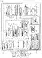
図1は、第1の実施の形態の画像表示システム120の構成を示すブロック図である。この画像表示システム120は、車両(本実施の形態では、自動車)に搭載されるものであり、車両の周囲を撮影して画像を生成して車室内に表示する機能を有している。画像表示システム120のユーザ(代表的にはドライバ)は、この画像表示システム120を利用することにより、当該車両の周囲の様子をほぼリアルタイムに把握できるようになっている。<First Embodiment>
<1-1. System configuration>
FIG. 1 is a block diagram illustrating a configuration of an
図1に示すように、画像表示システム120は、車両の周囲の様子を示す周辺画像を生成する画像生成装置100と、車両に乗車するユーザに対して各種情報を表示するナビゲーション装置20とを主に備えている。画像生成装置100で生成された周辺画像は、ナビゲーション装置20において表示される。 As shown in FIG. 1, the
ナビゲーション装置20は、ユーザに対しナビゲーション案内を行うものであり、タッチパネル機能を備えた液晶などのディスプレイ21と、ユーザが操作を行うハードスイッチなどの操作部22と、装置全体を制御する制御部23とを備えている。ディスプレイ21の画面がユーザから視認可能なように、ナビゲーション装置20は車両のインストルメントパネルなどに設置される。 The
ユーザの各種の指示は、操作部22とタッチパネルとしてのディスプレイ21とによって受け付けられる。制御部23は、CPU、RAM及びROMなどを備えたコンピュータであり、所定のプログラムに従ってCPUが演算処理を行うことでナビゲーション機能を含む各種の機能が実現される。ナビゲーション装置20は、画像生成装置100と通信可能に接続され、画像生成装置100との間で各種の制御信号の送受信や、画像生成装置100で生成された画像の受信が可能となっている。 Various user instructions are received by the
ディスプレイ21には、制御部23の制御により、通常は、ナビゲーション装置20単体の機能によって、ナビゲーション案内用の車両の周辺の地図画像が表示される。地図画像は、ナビゲーション装置20が備えるハードディスクなどに予め記憶されている。また、ナビゲーション装置20が備えるGPS装置によって車両の位置(緯度、経度)が取得され、この車両の位置に基づいて、車両の周辺の地図画像がディスプレイ21に表示される。表示する地図画像の縮尺はユーザの操作部22の操作に応じて変更可能である。 Under the control of the
一方で、画像表示システム120の動作モードを変更した場合は、画像生成装置100で生成された車両の周囲の様子を示す周辺画像が、ディスプレイ21に表示される。これにより、ナビゲーション装置20は、画像生成装置100で生成された周辺画像を受信して表示する表示装置としても機能する。 On the other hand, when the operation mode of the
画像生成装置100は、画像を生成する機能を有するECU(Electronic Control Unit)である本体部10と、車両の周囲を撮影する撮影部5とを備えている。本体部10は、車両の所定の位置に配置され、撮影部5で車両の周囲を撮影して得られる撮影画像に基づいてディスプレイ21に表示するための周辺画像を生成する。 The
撮影部5は、本体部10に電気的に接続され、本体部10からの信号に基づいて動作する。撮影部5は、車載カメラであるフロントカメラ51、サイドカメラ52、及び、バックカメラ53を備えている。各車載カメラ51〜53は、レンズと撮像素子とを備えており電子的に画像を取得する。 The photographing
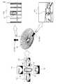
これらの複数の車載カメラ51〜53は、車両の異なる位置にそれぞれ配置される。図2は、車載カメラ51〜53が車両9に配置される位置を示す図である。 The plurality of in-
図2に示すように、フロントカメラ51は、車両9の前端にあるナンバープレート取付位置の近傍に設けられ、その光軸51aは車両9の直進方向に向けられている。バックカメラ53は、車両9の後端にあるナンバープレート取付位置の近傍に設けられ、その光軸53aは車両9の直進方向の逆方向に向けられている。これらフロントカメラ51やバックカメラ53の取り付け位置は、左右中央であることが望ましいが、左右中央から左右方向に多少ずれた位置であってもよい。また、サイドカメラ52は左右のサイドミラー93にそれぞれ設けられ、その光軸52aは車両9の左右方向(直進方向に直交する方向)に沿って車両9の外側に向けられている。 As shown in FIG. 2, the
これらの車載カメラ51〜53のレンズとしては魚眼レンズなどが採用されており、車載カメラ51〜53は180度以上の画角θを有している。このため、車載カメラは、それぞれの光軸を中心として、斜め下方や斜め上方の範囲の視野も撮影画像に移すことができる。撮影部5は、4つの車載カメラ51〜53を利用することで車両9の全周囲の撮影が可能となっている。 A fish-eye lens or the like is adopted as the lens of these in-
図1に戻り、画像生成装置100の本体部10は、装置全体を制御する制御部1と、撮影部5の4つの車載カメラ51〜53それぞれの撮影画像を入力する入力端子49と、表示用の周辺画像を生成する画像生成部3と、ナビゲーション装置20との間で通信を行うナビ通信部42を主に備えている。 Returning to FIG. 1, the
ナビゲーション装置20の操作部22やディスプレイ21によって受け付けられたユーザからの各種の指示は、制御信号としてナビ通信部42によって受け付けられて制御部1に入力される。また、画像生成装置100は、表示内容を切り替える指示をユーザから受け付ける切替スイッチ43を備えている。この切替スイッチ43からもユーザの指示を示す信号が制御部1に入力される。これにより、画像生成装置100は、ナビゲーション装置20に対するユーザの操作、及び、切替スイッチ43に対するユーザの操作の双方に応答した動作が可能となっている。切替スイッチ43は、ユーザが操作しやすいように、本体部10とは別に車両の適位置に配置される。切替スイッチ43は、後述するように、撮影画像間で表示の切替を行う表示切替手段としての役割も果たす。 Various instructions from the user received by the
画像生成部3は、各種の画像処理が可能なハードウェア回路であり、入力端子49を介して撮影部5から入力される撮影画像を処理し、ディスプレイ21に表示するための周辺画像を生成する。画像生成部3は、画像結合部30、メモリ31、画像調整部32、合成画像生成部34、画像配置部35、画像切替部36、ガイド線付加部37及びガイド線処理部38を主な構成要素として備えている。 The
画像結合部30は、撮影部5で取得された撮影画像を1枚の結合画像に結合する。図3の(A)及び図3の(B)は、画像結合部30によって生成される結合画像Pcnの説明図である。撮影部5のフロントカメラ51、サイドカメラ52及びバックカメラ53で同時に撮影が行われると、車両9の前方、左側方、右側方及び後方をそれぞれ示す4つの撮影画像P1〜P4が取得される。画像結合部30は、これら4枚の撮影画像P1〜P4を結合することによって、図3の(B)に示すような結合画像Pcnを生成する。画像結合部30によって生成された結合画像Pcnは、メモリ31に格納される。 The
画像調整部32は、画像結合部30にて生成された結合画像Pcnを表示に利用するための調整を行うものである。具体的には、画像調整部32は、結合画像Pcnに含まれる撮影画像P1〜P4に対して、歪み補正、拡大縮小、及び、切り出しなどの画像処理を行う。画像調整部32は、画像選択部33を備える。画像選択部33は、結合画像Pcnに含まれる撮影画像P1〜P4の切り出し処理の際に、切り出し範囲、すなわちディスプレイ21への表示範囲を選択する。 The
合成画像生成部34は、結合画像Pcnに基づいて、車両の周囲の任意の仮想視点からみた車両の周囲の領域を示す合成画像を生成する。合成画像生成部34が合成画像を生成する手法については後述する。 Based on the combined image Pcn, the composite
画像調整部32により表示用に調整された撮影画像、及び合成画像生成部34により生成された合成画像は、ナビ通信部42によってナビゲーション装置20に出力される。その際に、画像配置部35は、以下に説明する画像表示システム120の動作モードに応じて、画面上の所定の表示位置にこれらの画像を配置した表示画像を生成し、ナビゲーション装置20へ出力する。これにより、被写体像として車両の周囲の少なくとも一部の領域を含む周辺画像がナビゲーション装置20のディスプレイ21に表示されることになる。 The captured image adjusted for display by the
本明細書において、「周辺画像」とは、車両の周囲の少なくとも一部の領域を示す画像を意味し、表示用に調整された撮影画像、及び、合成画像の双方を含む概念である。表示用に調整された撮影画像は、取得された車載カメラ51〜53のレンズの位置を視点とし、その視点からみた周辺画像となる。また、合成画像は、車両の周囲の任意の位置に設定された仮想視点からみた周辺画像となる。 In this specification, the “peripheral image” means an image showing at least a part of the area around the vehicle, and is a concept including both a captured image adjusted for display and a composite image. The captured image adjusted for display is a peripheral image viewed from the viewpoint of the acquired lens position of the in-
画像切替部36は、撮影画像間で表示の切替を行うユーザ切替信号が切替スイッチ43から入力されるとディスプレイ21の表示画面に表示される撮影画像間の切替を行う。ガイド線付加部37は、後述するように、画像に各種ガイド線を付加する。ガイド線は、車両端が通過する軌跡を示す予想進路線、車両後端を示す距離目安線、車両後端に垂直後退した場合の進路を示す車幅平行線、ステアリングを左右に最大にきった場合の車両の予測軌跡を示す駐車ガイド線等とすることができる。ガイド線処理部38は、ガイド線付加部37が画像に付加したガイド線を消去し、かつ、画像をディスプレイ21の表示画面に表示する際にガイド線付加部37がガイド線を画像に付加するのを禁止する。 The
制御部1は、CPU、RAM及びROMなどを備えたコンピュータであり、所定のプログラムに従ってCPUが演算処理を行うことで各種の制御機能が実現される。図中に示す、画像制御部11、表示制御部12、切替信号受信部13、シフト位置信号受信部14、及び状態信号受信部15は、このようにして実現される制御部1の機能のうちの一部を示している。 The
画像制御部11は、画像生成部3によって実行される画像処理に係る制御を行う。例えば、画像制御部11は、合成画像生成部34が生成する合成画像の生成に必要な各種パラメータなどを指示する。 The
表示制御部12は、ナビゲーション装置20のディスプレイ21に表示する表示内容に係る制御を行う。例えば、画像表示システム120の動作モードの変更に応じて、ディスプレイ21の表示内容を切り替える。 The
切替信号受信部13は、ユーザ切替信号を受信することによって、ディスプレイ21の表示画面に表示される撮影画像間の切替を行うよう画像切替部36に指示する。シフト位置信号受信部14は、後述するシフト位置信号を受信することによって、シフトレバーのシフト位置に応じた画像をディスプレイ21の表示画面に表示するよう画像生成部3に指示する。状態信号受信部15は、後述する停止信号を受信することによって、車両の走行状態に応じた画像をディスプレイ21の表示画面に表示するよう画像生成部3に指示する。 The switching
画像生成装置100の本体部10は、不揮発性メモリ40、カード読取部44、及び、信号入力部41をさらに備えており、これらは制御部1に接続されている。 The
不揮発性メモリ40は、電源オフ時においても記憶内容を維持可能なフラッシュメモリなどである。不揮発性メモリ40には、視点データ4aが記憶されている。視点データ4aは、合成画像の仮想視点を定める際に利用される。 The
カード読取部44は、可搬性の記録媒体であるメモリカードMCの読み取りを行う。カード読取部44は、メモリカードMCの着脱が可能なカードスロットを備えており、そのカードスロットに装着されたメモリカードMCに記録されたデータを読み取る。カード読取部44で読み取られたデータは、制御部1に入力される。メモリカードMCは、種々のデータを記憶可能なフラッシュメモリなどであり、画像生成装置100はメモリカードMCに記憶された種々のデータを利用できる。例えば、メモリカードMCにプログラムを記憶させ、これを読み出すことで、制御部1の機能を実現するプログラム(ファームウェア)を更新することが可能である。 The
また、信号入力部41は、車両に設けられた各種装置からの信号を入力する。この信号入力部41を介して、画像表示システム120の外部からの信号が制御部1に入力される。本実施の形態では、シフトセンサ71、舵角センサ72及び車速センサ73からの信号が信号入力部41を介して制御部1に入力される。 Moreover, the
シフト位置検出手段としてのシフトセンサ71からは、車両の変速装置のシフトレバーの操作の位置、すなわち、”P(駐車)”,”D(前進)”,”N(中立)”,”R(後退)”などのシフトポジションを示すシフト位置信号が入力される。舵角センサ72からは、ドライバによるステアリングホイールの操作角を示す操作角信号が入力される。車両状態検出手段としての車速センサ73からは、車両の停止状態又は移動状態を検出する、車速パルスに基づく状態信号が入力される。
<1−2.画像合成処理>
次に、画像生成部3の合成画像生成部34が、撮影部5で得られた複数の撮影画像P1〜P4に基づいて車両9及び車両9の周辺を任意の仮想視点からみた様子を示す合成画像を生成する手法について説明する。図4は、合成画像を生成する手法を説明するための図である。From the shift sensor 71 as the shift position detecting means, the operation position of the shift lever of the vehicle transmission, that is, “P (parking)”, “D (forward)”, “N (neutral)”, “R ( A shift position signal indicating a shift position such as “backward” ”is input. From the
<1-2. Image composition processing>
Next, the composite
上述の通り、撮影部5のフロントカメラ51、サイドカメラ52及びバックカメラ53で同時に撮影が行われると、車両9の前方、左側方、右側方及び後方をそれぞれ示す4つの撮影画像P1〜P4が取得される。撮影部5で取得される4つの撮影画像P1〜P4を結合した結合画像Pcnには、撮影時点の車両9の全周囲を示す情報が含まれている。 As described above, when the
次に、結合画像Pcnの各画素が、仮想的な三次元空間における立体曲面TSに投影される。立体曲面TSは、例えば略半球状(お椀形状)をしており、その中心部分(お椀の底部分)が車両9が存在する位置として定められている。結合画像Pcnの各画素の位置とこの立体曲面TSの各画素の位置とは予め対応関係が定められている。このため、立体曲面TSの各画素の値は、この対応関係と結合画像Pcnに含まれる各画素の値とに基づいて決定できる。 Next, each pixel of the combined image Pcn is projected onto the three-dimensional curved surface TS in the virtual three-dimensional space. The three-dimensional curved surface TS has, for example, a substantially hemispherical shape (a bowl shape), and a center portion (a bottom portion of the bowl) is determined as a position where the
結合画像Pcnの各画素の位置と立体曲面TSの各画素の位置との対応関係は、車両9における4つの車載カメラ51〜53の配置(相互間距離、地上高さ、光軸角度等)に依存する。この対応関係を示すテーブルデータは、不揮発性メモリ40に予め記憶されている。 The correspondence relationship between the position of each pixel of the combined image Pcn and the position of each pixel of the three-dimensional curved surface TS depends on the arrangement of the four in-
また、不揮発性メモリ40に予め記憶された車体の形状やサイズを示すデータが利用され、車両9の三次元形状を示すポリゴンのモデルが仮想的に構成される。構成された車両9のモデルは、立体曲面TSが設定される三次元空間において、車両9の位置と定められた略半球状の中心部分に配置される。 Further, data indicating the shape and size of the vehicle body stored in advance in the
さらに、立体曲面TSが存在する三次元空間に対して、制御部1により仮想視点VPが設定される。仮想視点VPは、視点位置と視野方向とで規定され、この三次元空間における車両9の近傍に相当する任意の視点位置に任意の視野方向に向けて設定される。 Furthermore, the virtual viewpoint VP is set by the
そして、設定された仮想視点VPに応じて、立体曲面TSにおける必要な領域が画像として切り出される。仮想視点VPと、立体曲面TSにおける必要な領域との関係は予め定められており、テーブルデータとして不揮発性メモリ40等に予め記憶されている。一方で、設定された仮想視点VPに応じてポリゴンのモデルに関してレンダリングがなされ、その結果となる二次元の車両の像が、切り出された画像に対して重畳される。これにより、車両9及びその車両9の周囲を任意の仮想視点VPからみた様子を示す合成画像が生成されることになる。 Then, according to the set virtual viewpoint VP, a necessary area on the three-dimensional curved surface TS is cut out as an image. The relationship between the virtual viewpoint VP and a necessary area in the three-dimensional curved surface TS is determined in advance, and is stored in advance in the
例えば、視点位置が車両9の位置の略中央の直上で、視野方向が直下方向とした仮想視点VPaを設定した場合は、車両9の略直上から車両9を見下ろすように、車両9及び車両9の周囲の領域を示す合成画像CPaが生成される。また、図中に示すように、視点位置が車両9の位置の左後方で、視野方向が車両9における略前方方向とした仮想視点VPbを設定した場合は、車両9の左後方からその周辺全体を見渡すように、車両9及び車両9の周囲の領域を示す合成画像CPbが生成される。 For example, when a virtual viewpoint VPa is set in which the viewpoint position is just above the center of the position of the
なお、実際に合成画像を生成する場合においては、立体曲面TSの全ての画素の値を決定する必要はなく、設定された仮想視点VPに対応して必要となる領域の画素の値のみを撮影画像P1〜P4に基づいて決定することで、処理速度を向上できる。画像表示システム120では、このような合成画像生成部34の機能を利用することで、車両9の周囲の任意の視点からみた合成画像を生成して、ディスプレイ21に表示する。 In the case of actually generating a composite image, it is not necessary to determine the values of all the pixels of the three-dimensional curved surface TS, and only the values of the pixels in the area necessary corresponding to the set virtual viewpoint VP are photographed. By determining based on the images P1 to P4, the processing speed can be improved. In the
<1−3.動作モード>
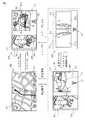
次に、画像表示システム120の動作モードについて説明する。図5は、画像表示システム120の動作モードの遷移を示す図である。画像表示システム120は、ナビモードM0、フロントモードM1、サイドモードM2、及び、バックモードM3の3つの動作モードを有している。これらの動作モードは、ドライバの車両9への操作や車両9の走行状態に応じて制御部1の制御により切り替えられるようになっている。<1-3. Operation mode>
Next, the operation mode of the
ナビモードM0は、ナビゲーション装置20の機能により、ナビゲーション案内を行う動作モードである。ナビモードM0では、画像生成装置100の機能が利用されず、ナビゲーション装置20単体の機能でディスプレイ21に各種の表示がなされる。具体的には、ディスプレイ21には、車両9の周辺の地図画像NPが主に表示される。 The navigation mode M0 is an operation mode in which navigation guidance is performed by the function of the
これに対し、フロントモードM1、サイドモードM2及びバックモードM3は、画像生成装置100の機能を利用して、周辺画像をディスプレイ21に表示して、車両の周囲の状況をリアルタイムでユーザに示す動作モードである。 On the other hand, the front mode M1, the side mode M2, and the back mode M3 use the function of the
フロントモードM1は、車両9の前方を表示する動作モードであり、見通しの悪い交差点への進入時などに利用される。ディスプレイ21の第2表示位置L2には、フロントカメラ51で取得されて表示用に調整した撮影画像(以下、「フロント画像」という。)SP1が表示される。このフロント画像SP1は、車両9の前方の視点(フロントカメラ51のレンズ位置)からみた周辺画像である。フロントモードM1では、表示中の周辺画像(すなわち、フロント画像)SP1の視点が車両9の前方であることを示すアイコンC1が表示される。 The front mode M1 is an operation mode for displaying the front of the
また、第1表示位置L1には、合成画像生成部34により生成された、車両9の略直上から車両9を見下ろすように車両9とその周辺の領域を示す合成画像CPaが表示される。 In addition, at the first display position L1, a composite image CPa that is generated by the composite
サイドモードM2は、車両9の側方を表示する動作モードであり、幅寄せを行う場合などに利用される。ディスプレイ21の第3表示位置L3及び第4表示位置L4には、サイドカメラ52で取得されて表示用に調整した撮影画像(以下、「サイド画像」という。)SP2が表示される。このサイド画像SP2は、車両9の側方の視点(サイドカメラ52のレンズ位置)からみた周辺画像である。サイドモードM2では、表示中の周辺画像(すなわち、サイド画像)SP2の視点が車両9の側方であることを示すアイコンC2が表示される。 The side mode M2 is an operation mode for displaying the side of the
また、バックモードM3は、車両9の後方を表示する動作モードであり、後退時に利用される。ディスプレイ21の第2表示位置L2には、バックカメラ53で取得されて表示用に調整した撮影画像(以下、「バック画像」という。)SP3が表示される。このバック画像SP3は、車両9の後方の視点(バックカメラ53のレンズ位置)からみた周辺画像である。バックモードM3では、表示中の周辺画像(すなわち、バック画像)SP3の視点が車両9の後方であることを示すアイコンC3が表示される。 The back mode M3 is an operation mode for displaying the rear of the
また、第1表示位置L1には、合成画像生成部34により生成された、車両9の略直上から車両9を見下ろすように車両9とその周囲の領域を示す合成画像CPaが表示される。 Further, at the first display position L1, a composite image CPa that is generated by the composite
ナビモードM0において、ナビゲーション装置20の操作部22に所定の操作(周辺画像の表示操作)がなされると、フロントモードM1及びサイドモードM2のうちの最後に有効化された動作モード(いわゆる、ラストモード)に切り替わる。フロントモードM1とサイドモードM2とは、切替スイッチ43を押下するごとに切り替えられる。また、フロントモードM1あるいはサイドモードM2において、ナビゲーション装置20の操作部22に所定の操作(周辺画像の表示操作)がなされると、ナビモードM0に戻る。 In the navigation mode M0, when a predetermined operation (peripheral image display operation) is performed on the
また、バックモードM3以外の動作モードにおいて、シフトセンサ71から入力されるシフトポジションが”R(後退)”となったときは、バックモードM3に切り替えられる。すなわち、シフトポジションが”R(後退)”の場合は、車両9は後退する状態であるため、車両9の後方を主に示すバックモードM3に切り替えられる。また、バックモードM3の場合に、シフトポジションが”R(後退)”以外となったときは、バックモードM3に切り替えられる直前の動作モードに戻ることになる。 In the operation mode other than the back mode M3, when the shift position input from the shift sensor 71 is “R (reverse)”, the mode is switched to the back mode M3. That is, when the shift position is “R (reverse)”, the
このように画像表示システム120は、複数の動作モードを切り替えることで、複数の視点からみた周辺画像を切り替えてディスプレイ21に表示可能となっている。なお、サイドミラーが格納されている場合には、正常な車両側面の撮影画像P2〜P3が得られない。したがって、サイドミラー格納時には、これら撮影画像P2〜P3に基づく画像は表示しない処理等を行う。 As described above, the
なお、フロントモードM1における合成画像CPaには、予想進路線S1が付加され、フロントモードM1におけるフロント画像SP1には、予想進路線S1,S2が付加され、バックモードM3における合成画像CPaには、予想進路線S3,S4及び距離目安線Mが付加され、バックモードM3におけるバック画像SP3には、予想進路線S4、距離目安線M及び車幅平行線Hが付加されている。 Note that the predicted route S1 is added to the composite image CPa in the front mode M1, the predicted routes S1 and S2 are added to the front image SP1 in the front mode M1, and the composite image CPa in the back mode M3 is Expected course lines S3, S4 and a distance guide line M are added, and an expected course line S4, a distance guide line M, and a vehicle width parallel line H are added to the back image SP3 in the back mode M3.
<1−4.ガイド線の付加及び消去処理>
次に、ガイド線を付加し又は消去するときの画像表示システム120の処理について説明する。図6は、ガイド線の付加及び消去の一例の説明図である。車両が停止した状態において、切替スイッチ43からの切替信号により、バックモードM3(シフトポジションが「R」)におけるディスプレイ21の表示画面のバック画像SP3をフロント画像SP1に切り替わると、ガイド線処理部38は、合成画像CPaから予想進路線S3,S4及び距離目安線Mを消去し、かつ、ガイド線付加部37がフロント画像SP1にガイド線を付加するのを禁止する。<1-4. Addition and deletion of guide lines>
Next, the processing of the
それに対し、車両が停止した状態において、切替スイッチ43からの切替信号により、バックモードM3におけるディスプレイ21の表示画面のフロント画像SP1をバック画像SP3に切り替えると、ガイド線付加部37は、合成画像CPaに予想進路線S3,S4及び距離目安線Mを付加し、バック画像SP3に予想進路線S4、距離目安線M及び車幅平行線Hを付加する。 On the other hand, when the front image SP1 of the display screen of the
また、バックモードM3におけるディスプレイ21の表示画面にフロント画像SP1を表示した状態で車両が停止状態から移動状態になると、ガイド線付加部37は、合成画像CPaに予想進路線S3,S4及び距離目安線Mを付加する。 In addition, when the vehicle is moved from the stopped state while the front image SP1 is displayed on the display screen of the
それに対し、バックモードM3におけるディスプレイ21の表示画面にフロント画像SP1を表示した状態で車両が移動状態から停止状態になると、ガイド線処理部38は、合成画像CPaから予想進路線S3,S4及び距離目安線Mを消去する。 On the other hand, when the vehicle changes from the moving state to the stopped state with the front image SP1 displayed on the display screen of the
続いて、図7を参照して、ガイド線の付加及び消去時における画像表示システム120の処理を説明する。なお、図7を参照して説明する処理例では、車両が停止状態でシフトポジションが「R」にあるときに繰り返し実行される。 Next, processing of the
オペレーションAAにおいて、車載カメラ51〜53は、それぞれ撮影画像P1〜P4を撮影する。オペレーションABにおいて、画像結合部30は、これらの画像P1〜P4を結合した結合画像Pcnを生成し、メモリ31に格納する。オペレーションACにおいて、合成画像生成部34は、結合画像Pcnに基づいて合成画像CPaを生成する。オペレーションADにおいて、切替信号受信部36は、ディスプレイ21の表示画面のバック画像SP3がフロント画像SP1に切り替えられたか否か判断する。バック画像SP3がフロント画像SP1に切り替えられない場合、オペレーションAEにおいて、ガイド線付加部37は、合成画像CPa及びバック画像SP3にガイド線を付加する。 In operation AA, the in-
オペレーションAFにおいて、画像配置部35は、現在の画像表示システム120の動作モードに従って、合成画像CPa及びバック画像SP3を選択し、ナビゲーション装置20へ出力する表示画像上に配置する。表示画像は、画像生成装置100によってナビゲーション装置20へ出力される。オペレーションAGにおいて、ナビゲーション装置20は、画像生成装置100から出力された表示画像をディスプレイ21へ表示する。 In operation AF, the
オペレーションADでバック画像SP3がフロント画像SP1に切り替えられたと判断された場合、オペレーションAHにおいて、状態信号受信部15は、車両が停止状態から移動状態になったか否か判断する。車両が停止状態から移動状態にならない場合、ガイド線処理部38は、合成画像CPaから予想進路線S3,S4及び距離目安線Mを消去し、ガイド線付加部37がフロント画像SP1にガイド線を付加するのを禁止し、オペレーションAFに進む。なお、オペレーションAHで車両が停止状態から移動状態になったと判断された場合、オペレーションAEに進む。 When it is determined in operation AD that the back image SP3 has been switched to the front image SP1, in operation AH, the state
第1の実施の形態によれば、ガイド線処理部38によるガイド線の消去又は付加禁止を行うことによって、車両が停止状態でシフトポジションが「R」にあるときに合成画像CPa及びフロント画像SP1がディスプレイ21の表示画面に表示されている場合でも、シフトポジションが「R」であることを運転者が容易に判断することができる。 According to the first embodiment, the guide line is erased or prohibited from being added by the guide
<2.第2の実施の形態>
<2−1.システム構成>
続いて第2の実施の形態について説明する。第2の実施の形態では、合成画像CPa及びフロント画像SP1又はバック画像SP3に付加するガイド線を選択し、合成画像CPaに付加されるガイド線に対応するフロント画像SP1又はバック画像SP3に付加されるガイド線は、同一色及び同一形状を有する。<2. Second Embodiment>
<2-1. System configuration>
Next, a second embodiment will be described. In the second embodiment, a guide line to be added to the composite image CPa and the front image SP1 or the back image SP3 is selected and added to the front image SP1 or the back image SP3 corresponding to the guide line to be added to the composite image CPa. The guide lines have the same color and the same shape.
合成画像CPaに付加されるガイド線に対応するフロント画像SP1又はバック画像SP3に付加されるガイド線の色と形状のうちの少なくとも一方が異なる場合、合成画像CPaに付加されるガイド線とフロント画像SP1又はバック画像SP2に付加されるガイド線との関係を把握しにくくなる。 When at least one of the color and shape of the guide line added to the front image SP1 or the back image SP3 corresponding to the guide line added to the composite image CPa is different, the guide line added to the composite image CPa and the front image It becomes difficult to grasp the relationship with the guide line added to SP1 or the back image SP2.
本実施の形態によれば、合成画像CPaに付加されるガイド線に対応するフロント画像SP1又はバック画像SP3に付加されるガイド線は、同一色及び同一形状を有するので、合成画像CPaに付加されるガイド線とフロント画像SP1又はバック画像SP2に付加されるガイド線との関係を把握しやすくなる。 According to the present embodiment, since the guide lines added to the front image SP1 or the back image SP3 corresponding to the guide lines added to the composite image CPa have the same color and the same shape, they are added to the composite image CPa. This makes it easier to grasp the relationship between the guide line added to the front image SP1 or the back image SP2.
図8は、第2の実施の形態の画像表示システム120の構成例を示す図である。図1に示す構成要素と同一の構成要素については同一の参照符号を付する。同一の参照符号が付された構成要素の動作は特に説明しない限り同じである。また、図8に示す構成要素やその機能を他の実施例が備えていてもよい。 FIG. 8 is a diagram illustrating a configuration example of the
画像生成部3は、ガイド線選択部39を有する。ガイド線選択部39は、切替スイッチ43からのユーザの指示を示す信号によって、合成画像CPaに付加されるガイド線とフロント画像SP1又はバック画像SP3に付加されるガイド線と選択し、選択したガイド線を合成画像CPa及びフロント画像SP1又はバック画像SP3に付加する。 The
<2−2.ガイド線の選択処理>
次に、ガイド線を選択するときの画像表示システム120の処理について説明する。図9は、ガイド線の選択の一例の説明図である。図9において、バックモードM3においてディスプレイ21の表示画面に合成画像CPa及びバック画像SP3が表示されている場合について説明するが、バック画像SP3の代わりにフロント画像SP1が表示されている場合でも同様の処理を行うことができ、フロントモードM1においても同様の処理を行うことができる。<2-2. Guide line selection process>
Next, processing of the
切替スイッチ43により、予想進路線を表示するよう指示された場合、合成画像CPaに対しては、予想進路線S3,S4及び距離目安線Mが選択され、これら予想進路線S3,S4及び距離目安線Mが合成画像CPaに付加され、バック画像SP3に対しては、予測進路線S4、距離目安線M及び車幅平行線Hが選択され、これら予想進路線S3,S4及び距離目安線Mがバック画像SP3に付加される。 When the
合成画像CPaに付加される予想進路線S3,S4及びバック画像SP3に付加される予想進路線S4は、第1の色(例えば、黄色)を有し、合成画像CPaに付加される距離目安線M及びバック画像SP3に付加される距離目安線Mは、第2の色(例えば、赤色)を有し、バック画像SP3に付加される車幅平行線Hは、第3の色(例えば、青色)を有する。 The expected course lines S3 and S4 added to the composite image CPa and the expected course line S4 added to the back image SP3 have a first color (for example, yellow) and are distance reference lines added to the composite image CPa. The distance reference line M added to M and the back image SP3 has the second color (for example, red), and the vehicle width parallel line H added to the back image SP3 is the third color (for example, blue). ).
また、合成画像CPaに付加される予想進路線S4は、バック画像S3に付加される予想進路線S4と同一形状を有し、合成画像CPaに付加される距離目安線Mは、バック画像S3に付加される距離目安線Mと同一形状を有する。 Further, the predicted route S4 added to the composite image CPa has the same shape as the predicted route S4 added to the back image S3, and the distance guide line M added to the composite image CPa is added to the back image S3. It has the same shape as the distance reference line M to be added.
その後、切替スイッチ43により、最大舵角線を表示するよう指示された場合、合成画像CPaに対しては、距離目安線Mが選択され、距離目安線Mが合成画像CPaに付加され、バック画像SP3に対しては、最大舵角線Gが距離目安線M及び車幅平行線Hとともに選択され、これら最大舵角線G、距離目安線M及び車幅平行線Hがバック画像SP3に付加される。 Thereafter, when the
合成画像CPaに付加される距離目安線M及びバック画像SP3に付加される距離目安線Mは、第2の色(例えば、赤色)を有し、バック画像SP3に付加される車幅平行線H及び最大舵角線Gは、第3の色(例えば、青色)を有する。また、合成画像CPaに付加される距離目安線Mは、バック画像S3に付加される距離目安線Mと同一形状を有する。 The distance guide line M added to the composite image CPa and the distance guide line M added to the back image SP3 have the second color (for example, red), and the vehicle width parallel line H added to the back image SP3. The maximum steering angle line G has a third color (for example, blue). Further, the distance guide line M added to the composite image CPa has the same shape as the distance guide line M added to the back image S3.
その後、切替スイッチ43により、車幅平行線及び最大舵角線を消去するよう指示された場合、合成画像CPaに対しては、距離目安線Mが選択され、距離目安線Mが合成画像CPaに付加され、バック画像SP3に対しては、距離目安線Mが選択され、距離目安線Mがバック画像SP3に付加される。 Thereafter, when the
合成画像CPaに付加される距離目安線M及びバック画像SP3に付加される距離目安線Mは、第2の色(例えば、赤色)を有する。また、合成画像CPaに付加される距離目安線Mは、バック画像S3に付加される距離目安線Mと同一形状を有する。 The distance guide line M added to the composite image CPa and the distance guide line M added to the back image SP3 have a second color (for example, red). Further, the distance guide line M added to the composite image CPa has the same shape as the distance guide line M added to the back image S3.
その後、切替スイッチ43により、予想進路線を表示するよう指示された場合、合成画像CPaに対しては、予想進路線S3,S4及び距離目安線Mが選択され、これら予想進路線S3,S4及び距離目安線Mが合成画像CPaに付加され、バック画像SP3に対しては、予測新路線S4、距離目安線M及び車幅平行線Hが選択され、これら予想進路線S3,S4及び距離目安線Mがバック画像SP3に付加される。 Thereafter, when the
続いて、図10を参照して、ガイド線を選択する画像表示システム120の処理を説明する。なお、他の実施態様においては、下記のオペレーションBA〜BJの各オペレーションはステップであってもよい。 Next, processing of the
オペレーションBAにおいて、車載カメラ51〜53は、それぞれ撮影画像P1〜P4を撮影する。オペレーションBBにおいて、画像結合部30は、これらの画像P1〜P4を結合した結合画像Pcnを生成し、メモリ31に格納する。オペレーションBCにおいて、合成画像生成部34は、結合画像Pcnに基づいて合成画像CPaを生成する。オペレーションBDにおいて、ガイド線選択部39は、合成画像CPa及びフロント画像SP1又はバック画像SP3に付加するガイド線を選択する。 In operation BA, the in-
オペレーションBEにおいて、画像配置部35は、現在の画像表示システム120の動作モードに従って、合成画像CPa及びバック画像SP3を選択し、ナビゲーション装置20へ出力する表示画像上に配置する。表示画像は、画像生成装置100によってナビゲーション装置20へ出力される。オペレーションBFにおいて、ナビゲーション装置20は、画像生成装置100から出力された表示画像をディスプレイ21へ表示する。 In operation BE, the
オペレーションBGにおいて、ガイド線選択部39は、切替スイッチ43によりガイド線を変更するよう指示があったか否か判断する。ガイド線を変更するよう指示があった場合、オペレーションBHにおいて、ガイド線選択部39は、ガイド線を再選択し、再選択したガイド線を合成画像CPa及びフロント画像SP1又はバック画像SP3にガイド線を付加する。 In operation BG, the guide line selection unit 39 determines whether there is an instruction to change the guide line by the
34 合成画像生成部
37 ガイド線付加部
38 ガイド線処理部
100 画像生成装置
120 画像表示システム34 Composite
Claims (4)
Translated fromJapanese車両に配置されたカメラと、
前記カメラで得られる撮影画像に基づいて車両及び車両の周囲を仮想視点から見た様子を示す合成画像を生成する合成画像生成手段と、
前記合成画像とともに前方撮影画像又は後方撮影画像を表示画面に表示する表示手段と、
前記合成画像にガイド線を付加するガイド線付加手段と、
車両の変速装置のシフトレバーのシフト位置を検出するシフト位置検出手段と、
車両の停止状態又は移動状態を検出する車両状態検出手段と、
前記合成画像とともに前記前方撮影画像が表示された状態において、車両が停止状態でシフト位置が後退位置にある場合に、前記合成画像へのガイド線の付加を禁止するガイド線処理手段と、
を備えることを特徴とする画像表示システム。An image display system mounted on a vehicle,
A camera located in the vehicle;
A composite image generating means for generating a composite image showing a state in which the vehicle and the surroundings of the vehicle are viewed from a virtual viewpoint based on a captured image obtained by the camera;
Display means for displaying afront photographed image or a rear photographed imagetogether with the composite image on a display screen;
Guide line adding means for adding a guide line to the composite image;
Shift position detecting means for detecting the shift position of the shift lever of the vehicle transmission,
Vehicle state detecting means for detecting a stop state or a moving state of the vehicle;
A guide line processing means for prohibiting the addition of a guide line to the composite image whenthe vehicle is stopped and the shift position is in the retracted position ina state where the front captured image is displayed together with the composite image ;
An image display system comprising:
前記合成画像とともに前方撮影画像又は後方撮影画像を表示装置の表示画面に表示する表示手段と、
前記合成画像にガイド線を付加するガイド線付加手段と、
車両の変速装置のシフトレバーのシフト位置を検出するシフト位置検出手段からのシフトポジション信号を受信するシフト位置信号受信手段と、
車両の停止状態又は移動状態を検出する車両状態検出手段からの信号を受信する状態信号受信手段と、
前記合成画像とともに前記前方撮影画像が表示された状態において、車両が停止状態でシフト位置が後退位置にある場合に、前記合成画像へのガイド線の付加を禁止するガイド線処理手段と、
を備えることを特徴とする画像生成装置。A composite image generating means for generating a composite image showing the vehicle and the surroundings of the vehicle viewed from a virtual viewpoint based on the captured image;
Display means for displaying afront captured image or a rear captured imagetogether with the composite image on a display screen of a display device;
Guide line adding means for adding a guide line to the composite image;
Shift position signal receiving means for receiving a shift position signal from a shift position detecting means for detecting a shift position of a shift lever of a vehicle transmission device; and
A state signal receiving means for receiving a signal from a vehicle state detecting means for detecting a stop state or a moving state of the vehicle;
A guide line processing means for prohibiting the addition of a guide line to the composite image whenthe vehicle is stopped and the shift position is in the retracted position ina state where the front captured image is displayed together with the composite image ;
An image generation apparatus comprising:
前記合成画像とともに前方撮影画像又は後方撮影画像を表示画面に表示し、
前記合成画像にガイド線を付加し、
車両の変速装置のシフトレバーのシフト位置を検出し、
車両の停止状態又は移動状態を検出し、
前記合成画像とともに前記前方撮影画像が表示された状態において、車両が停止状態でシフト位置が後退位置にある場合に、前記合成画像へのガイド線の付加を禁止する、
ステップを備えることを特徴とする画像表示方法。Based on the captured image obtained by the camera arranged in the vehicle, generate a composite image showing the vehicle and the surroundings of the vehicle viewed from a virtual viewpoint,
Afront shot image or a back shot image is displayed on the display screentogether with the composite image,
Add a guide line to the composite image,
Detects the shift position of the shift lever of the vehicle transmission,
Detecting the vehicle's stopped or moving state,
In a state where the front captured image is displayed together with the composite image, the addition of a guide line to the composite image is prohibited whenthe vehicle is stopped and the shift position is in the reverse position.
An image display method comprising a step.
Priority Applications (1)
| Application Number | Priority Date | Filing Date | Title |
|---|---|---|---|
| JP2011080783AJP5677168B2 (en) | 2011-03-31 | 2011-03-31 | Image display system, image generation apparatus, and image generation method |
Applications Claiming Priority (1)
| Application Number | Priority Date | Filing Date | Title |
|---|---|---|---|
| JP2011080783AJP5677168B2 (en) | 2011-03-31 | 2011-03-31 | Image display system, image generation apparatus, and image generation method |
Publications (2)
| Publication Number | Publication Date |
|---|---|
| JP2012216997A JP2012216997A (en) | 2012-11-08 |
| JP5677168B2true JP5677168B2 (en) | 2015-02-25 |
Family
ID=47269367
Family Applications (1)
| Application Number | Title | Priority Date | Filing Date |
|---|---|---|---|
| JP2011080783AActiveJP5677168B2 (en) | 2011-03-31 | 2011-03-31 | Image display system, image generation apparatus, and image generation method |
Country Status (1)
| Country | Link |
|---|---|
| JP (1) | JP5677168B2 (en) |
Families Citing this family (3)
| Publication number | Priority date | Publication date | Assignee | Title |
|---|---|---|---|---|
| JP6580872B2 (en) | 2015-06-05 | 2019-09-25 | 株式会社デンソーテン | Driving support device and driving support method |
| JP6954593B2 (en) | 2017-05-17 | 2021-10-27 | 株式会社デンソーテン | Display control device and display control method |
| JP7147548B2 (en)* | 2018-12-26 | 2022-10-05 | トヨタ自動車株式会社 | electronic mirror system |
Family Cites Families (2)
| Publication number | Priority date | Publication date | Assignee | Title |
|---|---|---|---|---|
| JP3803021B2 (en)* | 2000-10-02 | 2006-08-02 | 松下電器産業株式会社 | Driving assistance device |
| JP4973564B2 (en)* | 2008-03-27 | 2012-07-11 | 三菱自動車工業株式会社 | Vehicle periphery display device |
- 2011
- 2011-03-31JPJP2011080783Apatent/JP5677168B2/enactiveActive
Also Published As
| Publication number | Publication date |
|---|---|
| JP2012216997A (en) | 2012-11-08 |
Similar Documents
| Publication | Publication Date | Title |
|---|---|---|
| JP5743652B2 (en) | Image display system, image generation apparatus, and image generation method | |
| JP5302227B2 (en) | Image processing apparatus, image processing system, and image processing method | |
| JP5765995B2 (en) | Image display system | |
| JP5697512B2 (en) | Image generation apparatus, image display system, and image display apparatus | |
| JP5271154B2 (en) | Image generating apparatus and image display system | |
| US9706175B2 (en) | Image processing device, image processing system, and image processing method | |
| JP5858650B2 (en) | Image generation apparatus, image display system, and image generation method | |
| JP5548002B2 (en) | Image generation apparatus, image display system, and image generation method | |
| WO2011001794A1 (en) | Image generation device and image display system | |
| WO2011090163A1 (en) | Parameter determination device, parameter determination system, parameter determination method, and recording medium | |
| JP6548900B2 (en) | Image generation apparatus, image generation method and program | |
| JP5064601B2 (en) | In-vehicle video display | |
| JP5658507B2 (en) | Image display system, image generation apparatus, and image display method | |
| KR20120118073A (en) | Vehicle periphery monitoring device | |
| JP2011131678A (en) | Image processing device, image processing system and image processing method | |
| US20130250097A1 (en) | Method for displaying background screen in navigation device | |
| JP2016063390A (en) | Image processing apparatus and image display system | |
| JP5479639B2 (en) | Image processing apparatus, image processing system, and image processing method | |
| JP2013212723A (en) | Parking assist device and parking assist method | |
| WO2018159019A1 (en) | Bird's-eye-view video image generation device, bird's-eye-view video image generation system, bird's-eye-view video image generation method, and program | |
| JP5977130B2 (en) | Image generation apparatus, image display system, and image generation method | |
| JP5677168B2 (en) | Image display system, image generation apparatus, and image generation method | |
| JP2012046124A (en) | Image display system, image processing device and image display method | |
| JP6760129B2 (en) | Bird's-eye view image generation device, bird's-eye view image generation system, bird's-eye view image generation method and program | |
| JP5466743B2 (en) | Image generating apparatus and image display system |
Legal Events
| Date | Code | Title | Description |
|---|---|---|---|
| A621 | Written request for application examination | Free format text:JAPANESE INTERMEDIATE CODE: A621 Effective date:20130516 | |
| A977 | Report on retrieval | Free format text:JAPANESE INTERMEDIATE CODE: A971007 Effective date:20140207 | |
| A131 | Notification of reasons for refusal | Free format text:JAPANESE INTERMEDIATE CODE: A131 Effective date:20140401 | |
| A521 | Request for written amendment filed | Free format text:JAPANESE INTERMEDIATE CODE: A523 Effective date:20140526 | |
| TRDD | Decision of grant or rejection written | ||
| A01 | Written decision to grant a patent or to grant a registration (utility model) | Free format text:JAPANESE INTERMEDIATE CODE: A01 Effective date:20141202 | |
| A61 | First payment of annual fees (during grant procedure) | Free format text:JAPANESE INTERMEDIATE CODE: A61 Effective date:20141226 | |
| R150 | Certificate of patent or registration of utility model | Ref document number:5677168 Country of ref document:JP Free format text:JAPANESE INTERMEDIATE CODE: R150 | |
| R250 | Receipt of annual fees | Free format text:JAPANESE INTERMEDIATE CODE: R250 | |
| R250 | Receipt of annual fees | Free format text:JAPANESE INTERMEDIATE CODE: R250 | |
| S533 | Written request for registration of change of name | Free format text:JAPANESE INTERMEDIATE CODE: R313533 | |
| R350 | Written notification of registration of transfer | Free format text:JAPANESE INTERMEDIATE CODE: R350 | |
| S111 | Request for change of ownership or part of ownership | Free format text:JAPANESE INTERMEDIATE CODE: R313117 | |
| R250 | Receipt of annual fees | Free format text:JAPANESE INTERMEDIATE CODE: R250 | |
| R350 | Written notification of registration of transfer | Free format text:JAPANESE INTERMEDIATE CODE: R350 | |
| R250 | Receipt of annual fees | Free format text:JAPANESE INTERMEDIATE CODE: R250 | |
| R250 | Receipt of annual fees | Free format text:JAPANESE INTERMEDIATE CODE: R250 | |
| R250 | Receipt of annual fees | Free format text:JAPANESE INTERMEDIATE CODE: R250 |