JP5675390B2 - measuring device - Google Patents
measuring deviceDownload PDFInfo
- Publication number
- JP5675390B2 JP5675390B2JP2011009845AJP2011009845AJP5675390B2JP 5675390 B2JP5675390 B2JP 5675390B2JP 2011009845 AJP2011009845 AJP 2011009845AJP 2011009845 AJP2011009845 AJP 2011009845AJP 5675390 B2JP5675390 B2JP 5675390B2
- Authority
- JP
- Japan
- Prior art keywords
- acoustic wave
- subject
- acoustic
- light
- wave detector
- Prior art date
- Legal status (The legal status is an assumption and is not a legal conclusion. Google has not performed a legal analysis and makes no representation as to the accuracy of the status listed.)
- Expired - Fee Related
Links
Images


Classifications
- A—HUMAN NECESSITIES
- A61—MEDICAL OR VETERINARY SCIENCE; HYGIENE
- A61B—DIAGNOSIS; SURGERY; IDENTIFICATION
- A61B5/00—Measuring for diagnostic purposes; Identification of persons
- A61B5/0093—Detecting, measuring or recording by applying one single type of energy and measuring its conversion into another type of energy
- A61B5/0095—Detecting, measuring or recording by applying one single type of energy and measuring its conversion into another type of energy by applying light and detecting acoustic waves, i.e. photoacoustic measurements
- G—PHYSICS
- G01—MEASURING; TESTING
- G01S—RADIO DIRECTION-FINDING; RADIO NAVIGATION; DETERMINING DISTANCE OR VELOCITY BY USE OF RADIO WAVES; LOCATING OR PRESENCE-DETECTING BY USE OF THE REFLECTION OR RERADIATION OF RADIO WAVES; ANALOGOUS ARRANGEMENTS USING OTHER WAVES
- G01S7/00—Details of systems according to groups G01S13/00, G01S15/00, G01S17/00
- G01S7/52—Details of systems according to groups G01S13/00, G01S15/00, G01S17/00 of systems according to group G01S15/00
- G01S7/521—Constructional features
- G—PHYSICS
- G01—MEASURING; TESTING
- G01N—INVESTIGATING OR ANALYSING MATERIALS BY DETERMINING THEIR CHEMICAL OR PHYSICAL PROPERTIES
- G01N21/00—Investigating or analysing materials by the use of optical means, i.e. using sub-millimetre waves, infrared, visible or ultraviolet light
- G01N21/17—Systems in which incident light is modified in accordance with the properties of the material investigated
- G01N21/1702—Systems in which incident light is modified in accordance with the properties of the material investigated with opto-acoustic detection, e.g. for gases or analysing solids
- G—PHYSICS
- G10—MUSICAL INSTRUMENTS; ACOUSTICS
- G10K—SOUND-PRODUCING DEVICES; METHODS OR DEVICES FOR PROTECTING AGAINST, OR FOR DAMPING, NOISE OR OTHER ACOUSTIC WAVES IN GENERAL; ACOUSTICS NOT OTHERWISE PROVIDED FOR
- G10K11/00—Methods or devices for transmitting, conducting or directing sound in general; Methods or devices for protecting against, or for damping, noise or other acoustic waves in general
- G10K11/02—Mechanical acoustic impedances; Impedance matching, e.g. by horns; Acoustic resonators
- A—HUMAN NECESSITIES
- A61—MEDICAL OR VETERINARY SCIENCE; HYGIENE
- A61B—DIAGNOSIS; SURGERY; IDENTIFICATION
- A61B2562/00—Details of sensors; Constructional details of sensor housings or probes; Accessories for sensors
- A61B2562/14—Coupling media or elements to improve sensor contact with skin or tissue
- A—HUMAN NECESSITIES
- A61—MEDICAL OR VETERINARY SCIENCE; HYGIENE
- A61B—DIAGNOSIS; SURGERY; IDENTIFICATION
- A61B5/00—Measuring for diagnostic purposes; Identification of persons
- A61B5/0059—Measuring for diagnostic purposes; Identification of persons using light, e.g. diagnosis by transillumination, diascopy, fluorescence
- A61B5/0073—Measuring for diagnostic purposes; Identification of persons using light, e.g. diagnosis by transillumination, diascopy, fluorescence by tomography, i.e. reconstruction of 3D images from 2D projections
- A—HUMAN NECESSITIES
- A61—MEDICAL OR VETERINARY SCIENCE; HYGIENE
- A61B—DIAGNOSIS; SURGERY; IDENTIFICATION
- A61B5/00—Measuring for diagnostic purposes; Identification of persons
- A61B5/02—Detecting, measuring or recording for evaluating the cardiovascular system, e.g. pulse, heart rate, blood pressure or blood flow
- A61B5/026—Measuring blood flow
- A—HUMAN NECESSITIES
- A61—MEDICAL OR VETERINARY SCIENCE; HYGIENE
- A61B—DIAGNOSIS; SURGERY; IDENTIFICATION
- A61B5/00—Measuring for diagnostic purposes; Identification of persons
- A61B5/145—Measuring characteristics of blood in vivo, e.g. gas concentration or pH-value ; Measuring characteristics of body fluids or tissues, e.g. interstitial fluid or cerebral tissue
Landscapes
- Physics & Mathematics (AREA)
- Health & Medical Sciences (AREA)
- Life Sciences & Earth Sciences (AREA)
- Engineering & Computer Science (AREA)
- General Health & Medical Sciences (AREA)
- Acoustics & Sound (AREA)
- Pathology (AREA)
- General Physics & Mathematics (AREA)
- Immunology (AREA)
- Surgery (AREA)
- Biochemistry (AREA)
- Chemical & Material Sciences (AREA)
- Veterinary Medicine (AREA)
- Public Health (AREA)
- Animal Behavior & Ethology (AREA)
- Multimedia (AREA)
- Biophysics (AREA)
- Biomedical Technology (AREA)
- Heart & Thoracic Surgery (AREA)
- Medical Informatics (AREA)
- Molecular Biology (AREA)
- Analytical Chemistry (AREA)
- Computer Networks & Wireless Communication (AREA)
- Radar, Positioning & Navigation (AREA)
- Remote Sensing (AREA)
- Investigating Or Analyzing Materials By The Use Of Ultrasonic Waves (AREA)
- Ultra Sonic Daignosis Equipment (AREA)
Description
Translated fromJapanese本発明は測定装置に関する。 The present invention relates to a measuring apparatus.
一般に、エックス線、超音波、MRI(核磁気共鳴法)を用いた画像化装置が医療分野で多く使われている。一方、レーザーなどの光源から生体に照射した光を生体などの被検体内に伝播させ、その伝播光等を検知することで、生体内の情報を得る光画像化装置の研究が医療分野で積極的に進められている。このような光画像化技術の一つとして、光音響トモグラフィー(Photoacoustic Tomography:PAT)がある。
光音響トモグラフィーでは、光源から発生したパルス光を被検体に照射し、被検体内で伝播・拡散した光のエネルギーを吸収した生体組織から発生した音響波(典型的には超音波)の時間による変化を、被検体を取り囲む複数の個所で検出する。そして検出された信号を数学的に解析処理し、被検体内部の光学特性値に関連した情報を可視化する技術である。これにより、被検体内の光照射によって生じた初期圧力発生分布あるいは光エネルギー吸収密度分布などを得ることができ、新生血管の増殖を伴う悪性腫瘍場所の特定などに利用できる。なお、光音響画像化装置は光音響トモグラフィー技術を用いた画像化装置のことを意味している。
一般に、光音響トモグラフィーでは、被検体全体を取り囲む閉じられた空間表面(特に球面状測定表面の様々な点)において、音響波の時間変化を理想的な音響波検出器(広帯域・ポイント検出)を用いて測定することが好ましい。その測定結果に基づき、画像再構成の手法を用いて処理を行うことにより、理論的には光照射により生じた初期音圧分布を完全に可視化できる。
米国特許第6607489号公報には、画像再構成時の補正について記載されている。In general, imaging devices using X-rays, ultrasound, and MRI (nuclear magnetic resonance method) are widely used in the medical field. On the other hand, research on an optical imaging device that obtains in-vivo information by actively diffusing light irradiated on a living body from a light source such as a laser into a subject such as a living body and detecting the propagation light or the like in the medical field. Is underway. One such optical imaging technique is photoacoustic tomography (PAT).
In photoacoustic tomography, the subject is irradiated with pulsed light generated from a light source, and the time of the acoustic wave (typically ultrasound) generated from a living tissue that absorbs the energy of light that has propagated and diffused within the subject. Changes are detected at multiple locations surrounding the subject. Then, the detected signal is mathematically analyzed to visualize information related to the optical characteristic value inside the subject. Thereby, an initial pressure generation distribution or a light energy absorption density distribution generated by light irradiation in the subject can be obtained, and can be used for specifying a malignant tumor site accompanied by the growth of new blood vessels. Note that the photoacoustic imager means an imager using photoacoustic tomography technology.
In general, photoacoustic tomography uses an ideal acoustic wave detector (broadband and point detection) to measure temporal changes of acoustic waves on a closed space surface (especially various points on a spherical measurement surface) that surrounds the entire subject. It is preferable to use and measure. By performing processing using the image reconstruction method based on the measurement result, it is theoretically possible to completely visualize the initial sound pressure distribution generated by light irradiation.
US Pat. No. 6,607,489 describes correction at the time of image reconstruction.
しかしながら、一般の画像再構成理論では、光音響波を検出する音響波検出器がポイント検出(大きさがない)であると仮定している。実際には、音響波検出器は有限の大きさを有しており、その有限の大きさにより受信できる音響波の角度が制限される。通常、同じ強さで音響波検出器に垂直に入射する音響波(この線の角度は0とする)と、垂直な線に対して角度θで入射する音響波の感度の比は以下の式(1)で表すことができる。
このような理論から、画像再構成理論に適合させるためには、光音響トモグラフィーで
使用される音響波検出器は広範囲からの信号取得を可能にするような、指向性の低い物(検出幅が狭いもの)を用いることが好ましい。However, in general image reconstruction theory, it is assumed that the acoustic wave detector that detects the photoacoustic wave is point detection (no size). Actually, the acoustic wave detector has a finite size, and the angle of the acoustic wave that can be received is limited by the finite size. Usually, the ratio of the sensitivity of an acoustic wave that is perpendicularly incident on the acoustic wave detector with the same intensity (the angle of this line is 0) and the acoustic wave that is incident at an angle θ with respect to the vertical line is as follows: It can be represented by (1).
From such a theory, in order to adapt to the image reconstruction theory, the acoustic wave detector used in photoacoustic tomography has a low directivity (detection width is low) that enables signal acquisition from a wide range. Narrow ones are preferred.
一方では、検出時の素子感度を向上させるためには、検出幅は大きいことが望まれている。以下に、素子感度の関係を表す式(2)を示す。
本発明は上記実情に鑑みてなされたものであって、その目的とするところは、高感度な音響波の検出と、広範囲からの信号取得を両立できるような測定装置を提供することにある。 The present invention has been made in view of the above circumstances, and an object of the present invention is to provide a measuring apparatus capable of achieving both high-sensitivity acoustic wave detection and signal acquisition from a wide range.
上記の課題を解決するために、本発明は以下の構成を採用する。すなわち、光を照射することにより被検体から発生する音響波を検出する音響波検出器と、前記音響波検出器と被検体との間に配置され、被検体内の平均的な音速値よりも小さい音速値を有する部材と
、を有し、前記部材の厚さは、前記被検体から発生する音響波の波長よりも大きい測定装置であって、検出した音響波に基づいて被検体情報を取得する信号処理装置をさらに有し、前記信号処理装置は、音響波の発生した位置を決定する際に、前記部材内の音速値と前記被検体内の平均的な音速値との比による前記音響波検出器への音響波の入射角度の変化に基づいて、音響波の発生した位置までの距離を求め、被検体情報を取得することを特徴とする測定装置である。In order to solve the above problems, the present invention adopts the following configuration. That is, an acoustic wave detector that detects an acoustic wave generated from a subject by irradiating light, and the acoustic wave detector disposed between the acoustic wave detector and the subject, the average sound speed value in the subject A member having a small sound velocity value, and the thickness of the member is greater thanthe wavelength of the acoustic wave generated fromthe subject, and obtains subject information based on the detected acoustic wave The signal processing device further includes a signal processing device configured to determine the position where the acoustic wave is generated, and to determine the acoustic velocity based on a ratio between a sound velocity value in the member and an average sound velocity value in the subject. A measuring apparatus is characterizedin that, based on a change in an incident angle of an acoustic wave to a wave detector, a distance to a position where the acoustic wave is generated is obtained and subject information is obtained .
本発明の測定装置によれば、高感度な音響波の検出と、広範囲からの信号取得を両立できるようになる。 According to the measurement apparatus of the present invention, it is possible to achieve both highly sensitive acoustic wave detection and signal acquisition from a wide range.
以下、本発明の実施の形態について図面を参照しながら説明する。ここで説明する測定装置(光音響画像化装置)は、悪性腫瘍や血管疾患などの診断や化学治療の経過観察などを目的として、被検体情報の画像化を可能とするものである。なお被検体情報とは、光照射によって生じた音響波の発生源分布であり、被検体内の初期圧力分布、あるいはそれから導かれる光エネルギー吸収密度分布及び、それらの情報から得られる被検体組織を構成する物質の濃度分布を示す。例えば、物質の濃度分布とは酸素飽和度や酸化・還元ヘモグロビン濃度などである。 Hereinafter, embodiments of the present invention will be described with reference to the drawings. The measuring apparatus (photoacoustic imaging apparatus) described here enables imaging of subject information for the purpose of diagnosis of malignant tumors, vascular diseases and the like, and follow-up of chemical treatment. The object information is the source distribution of acoustic waves generated by light irradiation. The initial pressure distribution in the object, or the light energy absorption density distribution derived therefrom, and the object tissue obtained from the information. The concentration distribution of the constituent substances is shown. For example, the concentration distribution of the substance includes oxygen saturation and oxidized / reduced hemoglobin concentration.
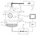
図1は、本発明の光音響画像化装置の実施形態について示したものである。光音響画像
化装置は、光12を被検体13に照射する光源11と、光源11から照射された光12を被検体13に導くレンズなどの光学装置14とを備える。また、被検体13内の血液などの光吸収体15が光のエネルギーの一部を吸収して発生した音響波16を検出し電気信号に変換する音響波検出器17と、音響波検出器に入射する音響波の入射角度を変換する低音速部材18を備える。低音速部材18はシート状の部材であることが望ましい。また、前記電気信号に増幅やデジタル変換などを行う電子制御システム19と、被検体情報に関する画像を構築する(つまり、画像データを生成する)信号処理装置20と、構築した画像を表示する表示装置21も備える。本実施形態では信号処理装置20としてPCを用いる。表示装置としてはディスプレイ等を用いることができる。FIG. 1 shows an embodiment of the photoacoustic imaging apparatus of the present invention. The photoacoustic imaging apparatus includes a
被検体に照射する光12をエネルギーが連続的に変化するパルスなどにすることで、被検体内部にある光吸収体15からは熱膨張により音響波16が発生する。これは、パルス光の吸収により、吸収体の温度が上昇し、その温度上昇により体積膨張が起こり、音響波が発生するためである。また、このときの光パルスの時間幅は光吸収体15に吸収エネルギーを効率的に閉じ込めるために、熱・ストレス閉じ込め条件が当てはまる程度にすることが好ましい。典型的には数から数十ナノ秒程度である。発生した光音響波16は低音速部材18を介して音響波検出器17により検出され、検出された電気信号は電子制御システム19により処理される。さらに、信号処理装置20により、その電気信号は被検体情報画像データへと変換され、表示装置21に表示される。 An
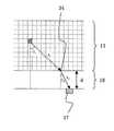
次に、本発明の低音速部材の効果について、図2を用いて詳細に説明する。図2は被検体13と音響波検出器17、低音速部材18の配置の一例を示したものである。本発明において、低音速部材18は被検体13と音響波検出器17の間に設置される。ここでは図示していないが、被検体13と低音速部材18、低音速部材18と音響波検出器17の間に音響インピーダンスマッチングのために、別の材料が挿入されていてもかまわない。ただし、その材料はできるだけ薄い方が好ましい。なお、低音速部材内の音響波の伝搬速度(低音速部材内の音速値)v2、被検体内の平均的な音響波の伝搬速度(被検体内の平均音速値)v1とすると、v1>v2となるようにしなければならない。その理由は後述する。また、低音速部材18の音響インピーダンス値は、被検体13と低音速部材18の間に音響インピーダンスマッチング材料を挿入しない場合は、被検体の音響インピーダンス値と近い値とすることが望ましい。この理由は、音響インピーダンスの差が大きいと、被検体から低音速部材18に入射した音響波の一部が反射されるからである。Next, the effect of the low sound speed member of the present invention will be described in detail with reference to FIG. FIG. 2 shows an example of the arrangement of the
また、低音速部材の厚さdは低音速部材の音速v2を音響波検出器17の検出可能な最小周波数fminで除算した値よりも大きいことが望ましい(d>v2/fmin)。ここで言う音響波検出器17の検出可能な最小周波数fminとは、典型的には最大感度の周波数fcに対して、感度が半分になる最小の周波数である。その理由は、低音速部材の厚さが検出する音響波の波長よりも大きくなければ、音速差による屈折が起こらないためである。具体的な数値をあげると、低音速部材としてシリコーンゴム(音速:〜1000m/秒)を考え、音響波検出器の検出可能な最小周波数を0.5MHzとすると、低音速部材の最小の厚さdは2mmとなる。
なお、低音速部材の厚さが上記の条件を満たす場合、被検体側から低音速部材に入射した音響波の角度θ1と低音速部材から音響波検出器に入射する音響波の角度θ2は下の式(3)に示したスネルの法則により決定される。そのため、低音速部材の音速v2が被検体の音速v1よりも小さければ、低音速部材から音響波検出器に入射する音響波の角度θ2は被検体側から低音速部材に入射した音響波の角度θ1よりも小さくなる。すなわち、低音速部材が設置されていない場合、指向性により検出しにくかった角度(例えばθ1)で音響波検出器に入射した音響波も、低音速部材を入れることで、音速の差により音響波が屈折して入射角度(例えばθ2)が変化する。これにより検出器が大きな感度を持つようになり、従来では検出できなかった角度からの音響波も検出できるようになる。
v1/v2=sinθ1/sinθ2 …(3)
さらに、低音速部材の最大の厚さdは低音速部材での音響波の減衰を抑えるために、低音速部材での減衰が20dB以下になる厚さが望ましい。さらに望ましくは、低音速部材の最大の厚さdは低音速部材の減衰が10dB以下になる厚さである。例えば、許容する低音速部材の減衰をA、低音速部材の周波数依存性減衰係数をα(単位:dB/MHz・cm)、音響波検出器17の検出可能な最大周波数をfmaxとすると低音速部材の最大厚さdmaxはdmax=A/(fmax×α)となる。なお、ここで言う音響波検出器17の検出可能な最大周波数fmaxとは、典型的には最大感度の周波数fcに対して、感度が半分になる最大の周波数である。このような厚さ以下に設定することで、低音速部材での音響波の減衰を低減できる。具体的な数値をあげると、低音速部材としてシリコーンゴム(減衰率:1.0dB/MHz・cm)を考え、許容する減衰を20dB、音響波検出器の検出可能な最大周波数を2MHzとすると、低音速部材の最大の厚さdは10mmとなる。低音速部材として他の部材を用いても、低音速部材の厚さは10mm以下が好ましい。さらに、低音速部材の厚さは8mm以下がより好ましく、最適には5mm以下がよい。Further, it is desirable that the thickness d of the low sound speed member is larger than the value obtained by dividing the sound speed v2 of the low sound speed member by the minimum frequency fmin detectable by the acoustic wave detector 17 (d> v2 / fmin ). The minimum frequency fmin that can be detected by the
When the thickness of the low sound speed member satisfies the above condition, the angle θ1 of the acoustic wave incident on the low sound speed member from the subject side and the angle θ2 of the acoustic wave incident on the acoustic wave detector from the low sound speed member Is determined by Snell's law as shown in equation (3) below. Therefore, if the sound velocity v2 of the low sound velocity member is smaller than the sound velocity v1 of the subject, the angle θ2 of the acoustic wave incident on the acoustic wave detector from the low sound velocity member is the sound incident on the low sound velocity member from the subject side. It becomes smaller than the wave angle θ1 . That is, when a low sound velocity member is not installed, an acoustic wave that has entered the acoustic wave detector at an angle that is difficult to detect due to directivity (for example, θ1 ) can also be generated due to the difference in sound speed by inserting the low sound velocity member. The wave is refracted and the incident angle (for example, θ2 ) changes. As a result, the detector has high sensitivity, and an acoustic wave from an angle that could not be detected conventionally can be detected.
v1 / v2 = sin θ1 / sin θ2 (3)
Further, it is desirable that the maximum thickness d of the low sound speed member is such that the attenuation at the low sound speed member is 20 dB or less in order to suppress the attenuation of the acoustic wave at the low sound speed member. More desirably, the maximum thickness d of the low sound velocity member is a thickness at which the attenuation of the low sound velocity member is 10 dB or less. For example, if the allowable attenuation of the low sound speed member is A, the frequency dependent attenuation coefficient of the low sound speed member is α (unit: dB / MHz · cm), and the maximum frequency detectable by the
なお、低音速部材としては、被検体の平均音速よりも小さい音速を持つものであれば良い。被検体が生体の場合、平均的な音速が〜1530m/秒である。それよりも音速が低い重水(〜1381m/秒)やエチルアルコール(〜1207m/秒)やメチルアルコール(〜1103m/秒)などの液体、シリコーンゴム(〜1000m/秒)などのゴムなどが使用できる。つまり、無機材料のような硬いものではなく、比較的やわらかい材料を選択することが好ましい。これらの材料は被検体の形状に対して柔軟に形状を変更できるため、被検体と低音速部材の間に空隙などの音響波伝播の阻害となる要因を低減できる。 The low sound speed member may be any member having a sound speed smaller than the average sound speed of the subject. When the subject is a living body, the average sound speed is ˜1530 m / sec. Liquids such as heavy water (up to 1381 m / second), ethyl alcohol (up to 1207 m / second), and methyl alcohol (up to 1103 m / second), and rubber such as silicone rubber (up to 1000 m / second) can be used. . That is, it is preferable to select a relatively soft material rather than a hard material such as an inorganic material. Since these materials can be flexibly changed in shape with respect to the shape of the subject, it is possible to reduce factors that hinder the propagation of acoustic waves, such as a gap, between the subject and the low acoustic velocity member.
次に、図3を用いて本発明の信号処理装置で行う処理の例について説明する。図3において、13は被検体、18は低音速部材、17は音響波検出器、34は音波の屈折点である。まず、画像再構成処理においては、画像化する被検体の領域13を離散化、すなわち、小さい領域に分解する。3次元画像を作る場合はボクセルに分割し、図3に示したように2次元画像を作る場合は、ピクセルに分割する。通常の画像再構成の場合は、注目している画素(ボクセルまたはピクセル)と検出点の距離及び、そのなす角度からその注目画素に加算する値を決定する。しかしながら、本実施形態では、低音速部材と被検体の界面(ここでは屈折点34)で音波が屈折するため音波の伝播距離が変化する。そのため、幾何学的な形状から屈折点の位置を求め、そこから注目画素から検出器までの音波の伝播距離(ここではr1+r2)を求める。さらに、角度θ2を求め、それらの値から注目画素
に加算する値を計算する。このような処理を施すことにより、低音速部材の音速により歪んだ画像を高精細化できる。Next, an example of processing performed by the signal processing apparatus of the present invention will be described with reference to FIG. In FIG. 3, 13 is a subject, 18 is a low acoustic velocity member, 17 is an acoustic wave detector, and 34 is a refracting point of sound waves. First, in the image reconstruction process, the
次に、本実施形態を具体的に説明する。
図1において、光源11は被検体を構成する成分のうち特定の成分に吸収される波長の光を照射することを目的とする。光源は光音響画像化装置と一体として設けられていても良いし、装置と分離して別体として設けられていても良い。
また光源は、数ナノから数百ナノ秒オーダーのパルス光を発生可能なパルス光源を少なくとも一つは備える。なお、検出する音響波の音圧が小さくてよい場合は、上記で記述したオーダーのパルス光ではなく、サイン波など時間的に強度が変化する光でもよい。本実施形態においては、光源11が一つである例を示しているが、複数の光源を用いても良い。その場合は、被検体に照射する光の照射強度を上げるため、同じ波長を発振する光源を複数用いても良いし、光学特性値分布の波長による違いを測定するために、発振波長の異なる光源を複数個用いても良い。Next, this embodiment will be specifically described.
In FIG. 1, a
The light source includes at least one pulsed light source capable of generating pulsed light on the order of several nanometers to several hundred nanoseconds. When the sound pressure of the acoustic wave to be detected may be small, it may be a light whose intensity changes with time, such as a sine wave, instead of the pulse light of the order described above. In the present embodiment, an example in which there is one
なお、光源としては大きな出力が得られるレーザーが好ましいが、レーザーのかわりに
発光ダイオードなどを用いることも可能である。レーザーとしては、固体レーザー、ガスレーザー、色素レーザー、半導体レーザーなど様々なレーザーを使用することができる。光源11として、発振する波長の変換可能な色素やOPO(Optical Parametric Oscillators)やチタンサファイヤ及びアレキサンドライトの結晶を用いれば、光学特性値分布の波長による違いを測定することも可能になる。
使用する光源の波長に関しては、被検体内において吸収が少ない700nmから1100nmの領域が好ましい。ただし、比較的被検体表面付近の被検体組織の光学特性値分布を求める場合は、上記の波長領域よりも範囲の広い、例えば400nmから1600nmの波長領域を使用することも可能である。Although a laser capable of obtaining a large output is preferable as the light source, a light emitting diode or the like can be used instead of the laser. As the laser, various lasers such as a solid laser, a gas laser, a dye laser, and a semiconductor laser can be used. If the
Regarding the wavelength of the light source to be used, a region of 700 nm to 1100 nm with little absorption in the subject is preferable. However, when obtaining the optical characteristic value distribution of the subject tissue relatively near the subject surface, it is also possible to use a wavelength region having a wider range than the above wavelength region, for example, a wavelength region of 400 nm to 1600 nm.
図1において、光源から照射された光12は、光導波路などを用いて、伝搬させることも可能である。図で示してはいないが光導波路としては、光ファイバが好ましい。光ファイバを用いる場合は、それぞれの光源に対して複数の光ファイバを使用して、被検体表面に光を導くことも可能であるし、複数の光源からの光を一本の光ファイバに導き、一本の光ファイバのみを用いて、すべての光を被検体に導いても良い。
図1の光学部品14は、主に光を反射するミラーや、光を集めたり拡大したり、形状を変化させるレンズなどを意味している。このような光学部品は、所望の形状で光源から発せられた光12が被検体13に照射されれば、どのようなものを用いてもかまわない。なお、一般的に光はレンズで集光させるより、ある程度の面積に広げる方が好ましい。また、光を被検体に照射する領域は移動可能であることが好ましい。言い換えると、本発明の光音響画像化装置は、光源から発生した光が被検体上を移動可能となるように構成されていることが好ましい。移動可能であることにより、より広範囲に光を照射することができる。また、光を被検体に照射する領域(被検体に照射される光)は、音響波検出器と同期して移動するとさらに好ましい。光を被検体に照射する領域を移動させる方法としては、上記ミラー等を可動式にして、照射領域を移動させてもよいし、光源自体を機械的に移動させてもよい。In FIG. 1, the light 12 irradiated from the light source can be propagated using an optical waveguide or the like. Although not shown in the drawing, an optical fiber is preferable as the optical waveguide. When optical fibers are used, it is possible to use a plurality of optical fibers for each light source to guide light to the surface of the subject, or to guide light from a plurality of light sources to a single optical fiber. All light may be guided to the subject using only one optical fiber.
The
被検体13としては、人や動物の悪性腫瘍や血管疾患などの診断や化学治療の経過観察などが目的であれば、人体や動物の乳房や指・手足などの部位を用いることができる。被検体の光吸収体15としては、被検体内で吸収係数が高いものが利用される。例えば、人体が測定対象であれば酸化ヘモグロビンあるいは還元ヘモグロビンや、それらを多く含む血管、あるいは新生血管を多く含む悪性腫瘍である。また、被検体の外部から導入した造影剤を光吸収体として利用することもできる。 As the subject 13, for the purpose of diagnosing a malignant tumor or vascular disease of a human or animal or observing the course of chemical treatment, it is possible to use a part of a human body or animal such as a breast, a finger or a limb. As the
図1の音響波検出器17は光吸収体から発生した音響波を検知し、電気信号に変換するものである。音響波検出器は、圧電現象を用いたトランスデューサー、光の共振を用いたトランスデューサー、容量の変化を用いたトランスデューサーなど音響波を検知できるものであれば、どのようなものでもよい。
なお、音響波検出器としては、複数の検出素子を2次元的に配置したものを好適に用いることができる。このような2次元配列素子を用いることで、同時に複数の場所で音響波を検出することができ、検出時間を短縮できると共に、被検体の振動などの影響を低減できる。このとき、検出幅de(ピッチ)は、一つの素子幅のことを指す。The
As the acoustic wave detector, a detector in which a plurality of detection elements are two-dimensionally arranged can be suitably used. By using such a two-dimensional array element, acoustic waves can be detected simultaneously at a plurality of locations, the detection time can be shortened, and influences such as vibration of the subject can be reduced. At this time, the detection width de (pitch) indicates one element width.
図1の低音速部材18は上で説明したように音響波検出器17に入射する音響波の入射角度を調整する。低音速部材18の音速値は被検体13の平均音速値よりも小さければ、どのような材料でも使用できる。典型的には液体やゴムなどのやわらかい材料であり、これにより被検体の形状に合わせて容易に自身の形状を変形できる利点がある。液体の場合はビニールなどからなる袋体または容器により保持することが好ましい。ゴムなどの場合はそのまま使用できる。なお、低音速部材18と被検体13、低音速部材18と音響波検出器17との間には、図示してはいないが音響波の反射を抑えるためのジェルなどの音響
インピーダンスマッチング剤を使うこともできる。また低音速部材は均質かつ厚さ一定なシート状の部材で構成することができる。つまり、低音速部材の厚さdを全領域で一定にし、かつ、均一な材料でシートを作成することができる。これにより、音響波検出器が2次元配列の素子で構成される時に、個々の素子について低音速部材を配置する必要がなくなる。また、音響波の屈折が起こったときの入射角や距離の演算が容易になる。The low
図1の電子制御システム19は音響波検出器17より得られた電気信号を増幅し、アナログ信号からデジタル信号に変換する。信号処理装置20は、電子制御システムから得られた測定データを記憶し、その測定データを演算手段により、光学特性値分布の画像データ(ボリュームデータ)に変換する。信号処理装置としては例えば、様々なデータを解析できるPCなどが使用できる。なお、画像データの生成手法(画像再構成手法)としては通常の光音響トモグラフィーで使われているユニバーサルバックプロジェクションなどのタイムドメイン法、フーリエドメイン法などを用いることができる。そして再構成した画像に上記の低音速部材の効果を考慮した補正を行うことで、より高精細な画像を形成できる。図1の画像表示装置21は信号処理装置20で作られた画像データを画像として表示できれば、どのようなものでも用いることができる。たとえば、液晶ディスプレイなどを利用できる。 The
以上のように、上述の条件を満たした低音速部材を用いた光音響画像化装置を用いることで、音響波検出器の検出幅を大きくしても、より大きな角度に入射した光音響波も検出できるので、より高精細な診断画像を形成できる。すなわち、検出幅の広い音響波検出器による高感度な検出と、広範囲からの信号取得との両立が可能になる。 As described above, even if the detection width of the acoustic wave detector is increased by using the photoacoustic imaging apparatus using the low acoustic velocity member that satisfies the above-described conditions, the photoacoustic wave incident at a larger angle is also detected. Since it can detect, a higher-definition diagnostic image can be formed. That is, it is possible to achieve both high-sensitivity detection by an acoustic wave detector having a wide detection width and signal acquisition from a wide range.
なお、光源に複数の波長の光を用いた場合は、それぞれの波長に関して、上記のシステムにより被検体内の吸収係数分布を算出する。そして、それらの値と被検体組織を構成する物質(グルコース、コラーゲン、酸化・還元ヘモグロビンなど)固有の波長依存性とを比較することによって、被検体を構成する物質の濃度分布を画像化することも可能である。 When light of a plurality of wavelengths is used as the light source, the absorption coefficient distribution in the subject is calculated for each wavelength by the above system. Then, by comparing these values with the wavelength dependence specific to the substance (glucose, collagen, oxidized / reduced hemoglobin, etc.) constituting the specimen tissue, imaging the concentration distribution of the substance constituting the specimen Is also possible.
<変形例>
続いて、測定装置(光音響画像化装置)の構成を一部変形した例について説明する。図4は、この変形例における装置の構成を示すブロック図である。図1の装置と異なる点は、被検体13を、第1の保持板22と、第2の保持板23で圧迫していることである。第1の保持板22としては、光源からの光に対して高透過性と低減衰特性を持つ平板が用いられる。第2の保持板23としては、音響波に対して高透過性と低減衰特性を持つ平板が用いられる。このように2つの保持板を用いれば、被検体13の動きを抑制、保持することが可能となる。
そして、第2の保持板23と音響波検出器17との間に低音速部材18を配置する。これにより、上の実施形態と同様に、高感度な音響波の検出と広範囲からの信号取得を両立するという効果を得ることができる。なお必要に応じて、第2の保持板23と、被検体13または低音速部材18の間に音響インピーダンスマッチングのための材料を挿入してもかまわない。
特に低音速部材としてシート状の材料を用いる場合、第2の保持板23にシートを貼り付けるだけで良いので、装置を容易に構成することができる。この場合、低音速部材は第2の保持板上に配置されていることになる。<Modification>
Next, an example in which the configuration of the measurement apparatus (photoacoustic imaging apparatus) is partially modified will be described. FIG. 4 is a block diagram showing the configuration of the apparatus in this modification. The difference from the apparatus of FIG. 1 is that the subject 13 is pressed by the first holding
Then, the low
In particular, when a sheet-like material is used as the low sound velocity member, it is only necessary to attach the sheet to the
11:光源,17:音響波検出器,18:低音速部材,19:電子制御システム,20:信号処理装置,21:画像表示装置 11: Light source, 17: Acoustic wave detector, 18: Low sound speed member, 19: Electronic control system, 20: Signal processing device, 21: Image display device
Claims (4)
Translated fromJapanese前記音響波検出器と被検体との間に配置され、被検体内の平均的な音速値よりも小さい音速値を有する部材と、を有し、
前記部材の厚さは、前記被検体から発生する音響波の波長よりも大きい測定装置であって、
検出した音響波に基づいて被検体情報を取得する信号処理装置をさらに有し、
前記信号処理装置は、音響波の発生した位置を決定する際に、前記部材内の音速値と前記被検体内の平均的な音速値との比による前記音響波検出器への音響波の入射角度の変化に基づいて、音響波の発生した位置までの距離を求め、被検体情報を取得することを特徴とする測定装置。An acoustic wave detector that detects acoustic waves generated from the subject by irradiating light; and
A member disposed between the acoustic wave detector and the subject and having a sound velocity value smaller than an average sound velocity value in the subject, and
The thickness of the member is ameasuring device larger thanthe wavelength of the acoustic wave generated from the subject,
A signal processing device for acquiring subject information based on the detected acoustic wave;
When the signal processing apparatus determines the position where the acoustic wave is generated, the acoustic wave is incident on the acoustic wave detector based on a ratio between the sound speed value in the member and the average sound speed value in the subject. A measuring apparatusthat obtains object information by obtaining a distance to a position where an acoustic wave is generated based on a change in angle .
前記第1の保持板と共に前記被検体を保持する第2の保持板とをさらに有し、
前記部材は、前記第2の保持板と前記音響波検出器との間に配置されている
ことを特徴とする請求項1に記載の測定装置。A first holding plate;
Further comprising a second holding plate for holdingthe object withprevious SL first holding plate,
Themember measuring device accordingto claim1, characterized in that it is disposedbetween the acoustic wave detector and the second holding plate.
Priority Applications (2)
| Application Number | Priority Date | Filing Date | Title |
|---|---|---|---|
| JP2011009845AJP5675390B2 (en) | 2010-02-09 | 2011-01-20 | measuring device |
| US13/020,048US8654613B2 (en) | 2010-02-09 | 2011-02-03 | Measuring apparatus |
Applications Claiming Priority (3)
| Application Number | Priority Date | Filing Date | Title |
|---|---|---|---|
| JP2010026600 | 2010-02-09 | ||
| JP2010026600 | 2010-02-09 | ||
| JP2011009845AJP5675390B2 (en) | 2010-02-09 | 2011-01-20 | measuring device |
Publications (2)
| Publication Number | Publication Date |
|---|---|
| JP2011183149A JP2011183149A (en) | 2011-09-22 |
| JP5675390B2true JP5675390B2 (en) | 2015-02-25 |
Family
ID=44353627
Family Applications (1)
| Application Number | Title | Priority Date | Filing Date |
|---|---|---|---|
| JP2011009845AExpired - Fee RelatedJP5675390B2 (en) | 2010-02-09 | 2011-01-20 | measuring device |
Country Status (2)
| Country | Link |
|---|---|
| US (1) | US8654613B2 (en) |
| JP (1) | JP5675390B2 (en) |
Families Citing this family (11)
| Publication number | Priority date | Publication date | Assignee | Title |
|---|---|---|---|---|
| JP5692988B2 (en)* | 2009-10-19 | 2015-04-01 | キヤノン株式会社 | Acoustic wave measuring device |
| JP5528083B2 (en) | 2009-12-11 | 2014-06-25 | キヤノン株式会社 | Image generating apparatus, image generating method, and program |
| JP5743715B2 (en)* | 2011-05-26 | 2015-07-01 | キヤノン株式会社 | Acoustic signal receiver |
| JP5932243B2 (en)* | 2011-05-31 | 2016-06-08 | キヤノン株式会社 | apparatus |
| JP5834679B2 (en)* | 2011-09-20 | 2015-12-24 | セイコーエプソン株式会社 | Ultrasonic probe and ultrasonic diagnostic imaging apparatus |
| JP2013075000A (en)* | 2011-09-30 | 2013-04-25 | Fujifilm Corp | Photoacoustic image generating apparatus and method |
| CN104168833B (en)* | 2012-06-04 | 2016-03-09 | 株式会社爱德万测试 | Photoacoustic wave measuring device and method |
| WO2013183400A1 (en)* | 2012-06-04 | 2013-12-12 | 株式会社アドバンテスト | Photoacoustic wave measurement device |
| JP6238737B2 (en)* | 2013-12-26 | 2017-11-29 | キヤノン株式会社 | Photoacoustic apparatus, signal processing method, and program |
| JP6946307B2 (en) | 2016-08-30 | 2021-10-06 | キヤノン株式会社 | Information acquisition device and signal processing method |
| JP6480979B2 (en)* | 2017-05-10 | 2019-03-13 | ファナック株式会社 | Measuring device |
Family Cites Families (18)
| Publication number | Priority date | Publication date | Assignee | Title |
|---|---|---|---|---|
| WO1995011627A1 (en)* | 1993-10-29 | 1995-05-04 | Neovision Corporation | Methods and apparatus for performing sonomammography and enhanced x-ray imaging |
| US6607489B2 (en)* | 2001-04-05 | 2003-08-19 | General Electric Company | Focus correction for ultrasound imaging through mammography compression plate |
| US20060184042A1 (en)* | 2005-01-22 | 2006-08-17 | The Texas A&M University System | Method, system and apparatus for dark-field reflection-mode photoacoustic tomography |
| JP4422626B2 (en) | 2005-01-25 | 2010-02-24 | 日本電信電話株式会社 | Biological imaging device |
| US7466256B2 (en)* | 2006-03-31 | 2008-12-16 | Siemens Medical Solutions Usa, Inc. | Universal ultrasound sigma-delta receiver path |
| JP2007319597A (en)* | 2006-06-05 | 2007-12-13 | Toshiba Corp | Ultrasonic probe and ultrasonic diagnostic apparatus |
| JP5162923B2 (en)* | 2007-02-27 | 2013-03-13 | 株式会社日立製作所 | Ultrasonic imaging device |
| JP4739363B2 (en)* | 2007-05-15 | 2011-08-03 | キヤノン株式会社 | Biological information imaging apparatus, biological information analysis method, and biological information imaging method |
| EP2002784B1 (en) | 2007-06-11 | 2018-07-11 | Canon Kabushiki Kaisha | Intravital-information imaging apparatus |
| US20090005685A1 (en)* | 2007-06-29 | 2009-01-01 | Canon Kabushiki Kaisha | Ultrasonic probe and inspection apparatus equipped with the ultrasonic probe |
| JP5546111B2 (en)* | 2007-06-29 | 2014-07-09 | キヤノン株式会社 | Ultrasonic probe and inspection apparatus provided with the ultrasonic probe |
| JP5284129B2 (en) | 2008-02-06 | 2013-09-11 | キヤノン株式会社 | Imaging apparatus and analysis method |
| JP5460000B2 (en) | 2008-08-20 | 2014-04-02 | キヤノン株式会社 | Imaging apparatus and imaging method |
| JP5496098B2 (en) | 2008-08-27 | 2014-05-21 | キヤノン株式会社 | Subject information acquisition apparatus and control method thereof |
| JP4900979B2 (en) | 2008-08-27 | 2012-03-21 | キヤノン株式会社 | Photoacoustic apparatus and probe for receiving photoacoustic waves |
| JP5419404B2 (en) | 2008-09-04 | 2014-02-19 | キヤノン株式会社 | Photoacoustic device |
| JP2010088627A (en) | 2008-10-07 | 2010-04-22 | Canon Inc | Apparatus and method for processing biological information |
| JP2011005042A (en) | 2009-06-26 | 2011-01-13 | Canon Inc | Photoacoustic imaging apparatus and photoacoustic imaging method |
- 2011
- 2011-01-20JPJP2011009845Apatent/JP5675390B2/ennot_activeExpired - Fee Related
- 2011-02-03USUS13/020,048patent/US8654613B2/ennot_activeExpired - Fee Related
Also Published As
| Publication number | Publication date |
|---|---|
| US8654613B2 (en) | 2014-02-18 |
| JP2011183149A (en) | 2011-09-22 |
| US20110194380A1 (en) | 2011-08-11 |
Similar Documents
| Publication | Publication Date | Title |
|---|---|---|
| JP5675390B2 (en) | measuring device | |
| EP2553425B1 (en) | Photoacoustic imaging apparatus and photoacoustic imaging method | |
| JP5541662B2 (en) | Subject information acquisition apparatus and control method thereof | |
| KR102144551B1 (en) | Laser optoacoustic ultrasonic imaging system (louis) and methods of use | |
| JP5586977B2 (en) | Subject information acquisition apparatus and subject information acquisition method | |
| US8260403B2 (en) | Photoacoustic imaging apparatus and photoacoustic imaging method | |
| CN103458778B (en) | Subject information acquisition equipment | |
| JP4469903B2 (en) | Biological information imaging device | |
| US20100191109A1 (en) | Biological information processing apparatus and biological information processing method | |
| JP2010088627A5 (en) | ||
| EP2482713B1 (en) | Photoacoustic measuring apparatus | |
| JP2010088627A (en) | Apparatus and method for processing biological information | |
| US20110261056A1 (en) | Display data obtaining apparatus and display data obtaining method | |
| US20110178385A1 (en) | Photoacoustic measuring apparatus with movable detector array | |
| JP2011217914A (en) | Photoacoustic imaging apparatus, photoacoustic imaging method, and program | |
| US20140296690A1 (en) | Object information acquiring apparatus and object information acquiring method | |
| JP2017047177A (en) | Subject information acquiring apparatus and control method for subject information acquiring apparatus | |
| US20130267823A1 (en) | Measuring apparatus | |
| US20170303793A1 (en) | Photoacoustic apparatus and information acquisition apparatus | |
| JP2013188489A (en) | Subject information processing apparatus and method for operating the same |
Legal Events
| Date | Code | Title | Description |
|---|---|---|---|
| A621 | Written request for application examination | Free format text:JAPANESE INTERMEDIATE CODE: A621 Effective date:20140116 | |
| A977 | Report on retrieval | Free format text:JAPANESE INTERMEDIATE CODE: A971007 Effective date:20140829 | |
| A131 | Notification of reasons for refusal | Free format text:JAPANESE INTERMEDIATE CODE: A131 Effective date:20140902 | |
| A521 | Request for written amendment filed | Free format text:JAPANESE INTERMEDIATE CODE: A523 Effective date:20141104 | |
| TRDD | Decision of grant or rejection written | ||
| A01 | Written decision to grant a patent or to grant a registration (utility model) | Free format text:JAPANESE INTERMEDIATE CODE: A01 Effective date:20141125 | |
| A61 | First payment of annual fees (during grant procedure) | Free format text:JAPANESE INTERMEDIATE CODE: A61 Effective date:20141224 | |
| R151 | Written notification of patent or utility model registration | Ref document number:5675390 Country of ref document:JP Free format text:JAPANESE INTERMEDIATE CODE: R151 | |
| LAPS | Cancellation because of no payment of annual fees |