JP5672326B2 - Robot system - Google Patents
Robot systemDownload PDFInfo
- Publication number
- JP5672326B2 JP5672326B2JP2013056649AJP2013056649AJP5672326B2JP 5672326 B2JP5672326 B2JP 5672326B2JP 2013056649 AJP2013056649 AJP 2013056649AJP 2013056649 AJP2013056649 AJP 2013056649AJP 5672326 B2JP5672326 B2JP 5672326B2
- Authority
- JP
- Japan
- Prior art keywords
- workpiece
- work
- image
- input
- touch panel
- Prior art date
- Legal status (The legal status is an assumption and is not a legal conclusion. Google has not performed a legal analysis and makes no representation as to the accuracy of the status listed.)
- Expired - Fee Related
Links
Images


Classifications
- G—PHYSICS
- G06—COMPUTING OR CALCULATING; COUNTING
- G06F—ELECTRIC DIGITAL DATA PROCESSING
- G06F18/00—Pattern recognition
- G06F18/40—Software arrangements specially adapted for pattern recognition, e.g. user interfaces or toolboxes therefor
- G06F18/41—Interactive pattern learning with a human teacher
- G—PHYSICS
- G06—COMPUTING OR CALCULATING; COUNTING
- G06F—ELECTRIC DIGITAL DATA PROCESSING
- G06F3/00—Input arrangements for transferring data to be processed into a form capable of being handled by the computer; Output arrangements for transferring data from processing unit to output unit, e.g. interface arrangements
- G06F3/01—Input arrangements or combined input and output arrangements for interaction between user and computer
- G06F3/03—Arrangements for converting the position or the displacement of a member into a coded form
- G06F3/041—Digitisers, e.g. for touch screens or touch pads, characterised by the transducing means
- G—PHYSICS
- G06—COMPUTING OR CALCULATING; COUNTING
- G06V—IMAGE OR VIDEO RECOGNITION OR UNDERSTANDING
- G06V2201/00—Indexing scheme relating to image or video recognition or understanding
- G06V2201/06—Recognition of objects for industrial automation
Landscapes
- Engineering & Computer Science (AREA)
- Theoretical Computer Science (AREA)
- General Engineering & Computer Science (AREA)
- Computer Vision & Pattern Recognition (AREA)
- Physics & Mathematics (AREA)
- Human Computer Interaction (AREA)
- General Physics & Mathematics (AREA)
- Artificial Intelligence (AREA)
- Evolutionary Biology (AREA)
- Evolutionary Computation (AREA)
- Data Mining & Analysis (AREA)
- Bioinformatics & Computational Biology (AREA)
- Bioinformatics & Cheminformatics (AREA)
- Life Sciences & Earth Sciences (AREA)
- Manipulator (AREA)
- Numerical Control (AREA)
Description
Translated fromJapanese本発明は、ロボットアームとワークの撮影用のカメラとを備えるロボットシステムに関する。 The present invention relates to a robot system including a robot arm and a camera for shooting a workpiece.
カメラによりワークを撮影し、撮影した画像に基づいてワークの位置情報等を取得し、取得した位置情報等に基づいてロボットアームに作業を行わせるロボットシステムが実用化されている。例えば、特許文献1には、ロボットアームと、ワークの撮影用にロボットアームに取り付けられたカメラと、を備えるロボットシステムが開示されている。 A robot system has been put to practical use in which a workpiece is photographed by a camera, position information of the workpiece is acquired based on the captured image, and a robot arm is operated based on the acquired position information. For example, Patent Document 1 discloses a robot system including a robot arm and a camera attached to the robot arm for photographing a workpiece.
上述したロボットシステムにおいて、ワークの位置情報等を取得するためには、撮影した画像内においてワークを認識するための画像認識プログラムを予め登録しておく必要がある。適切な画像認識プログラムを登録するには、画像認識についての高度の専門知識に基づく難しい作業が必要であった。 In the robot system described above, in order to acquire workpiece position information and the like, it is necessary to register in advance an image recognition program for recognizing the workpiece in the captured image. In order to register an appropriate image recognition program, a difficult task based on advanced expertise in image recognition was required.
そこで本発明は、ワークの画像認識プログラムを容易に登録できるロボットシステムを提供することを目的とする。 Accordingly, an object of the present invention is to provide a robot system that can easily register a workpiece image recognition program.
本発明に係るロボットシステムは、ロボットアームと、ワークの撮影用に設置されたカメラと、タッチパネルと、カメラにより撮影された画像から、画像認識プログラムに従ってワークを認識する画像処理装置とを備え、画像処理装置は、ワークに関する複数のパラメータの入力により、画像認識プログラムとなるベースプログラムの記憶部と、パラメータの入力を促す複数の入力画面を一画面ずつタッチパネルに表示し、一つの入力画面におけるパラメータの入力が完了する度に次の入力画面に切り替えることで全てのパラメータをタッチパネルから順次取得するワーク登録ガイド部と、ワーク登録ガイド部が取得したパラメータを記憶部のベースプログラムにあてはめることで画像認識プログラムを構築し、登録する登録部とを有する。 A robot system according to the present invention includes a robot arm, a camera installed for shooting a workpiece, a touch panel, and an image processing device that recognizes a workpiece from an image shot by the camera according to an image recognition program. The processing device displays a storage unit of a base program serving as an image recognition program and a plurality of input screens for prompting parameter input on the touch panel one screen at a time by inputting a plurality of parameters related to the workpiece. A work registration guide unit that sequentially acquires all parameters from the touch panel by switching to the next input screen every time input is completed, and an image recognition program by applying the parameters acquired by the work registration guide unit to the base program of the storage unit And a registration unit for registering.
本発明によれば、ワークの画像認識プログラムを容易に登録できる。 According to the present invention, a workpiece image recognition program can be easily registered.
以下、本発明の好適な実施形態について、図面を参照しつつ詳細に説明する。説明において、同一要素又は同一機能を有する要素には同一の符号を付し、重複する説明を省略する。 DESCRIPTION OF EMBODIMENTS Hereinafter, preferred embodiments of the present invention will be described in detail with reference to the drawings. In the description, the same elements or elements having the same functions are denoted by the same reference numerals, and redundant description is omitted.
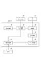
図1に示すように、実施形態に係るロボットシステム1は、ロボットアーム10と、ロボットコントローラ20と、作業台30と、カメラ40とを備える。 As shown in FIG. 1, the robot system 1 according to the embodiment includes a
ロボットアーム10は、基部11と、2本の腕部12,13と、1本の手首部14と、基部11に対して腕部12,13及び手首部14を直列に連結する3箇所の関節15,16,17とを有する。基部11は、床面に設置される基台11aと、基台11aの上に設けられた旋回台11bとを有する。基台11aは、鉛直な軸(S軸)A1まわりに旋回台11bを旋回させるアクチュエータを内蔵している。 The
関節(L軸関節)15は、腕部(下腕部)12と旋回台11bの上部とを連結する。L軸関節15は、水平な軸(L軸)A2まわりに下腕部12を揺動させるアクチュエータを内蔵している。関節(U軸関節)16は、腕部(前腕部)13と下腕部12とを連結する。U軸関節16は、L軸A2に平行な軸(U軸)A3まわりに前腕部13を搖動させるアクチュエータを内蔵している。関節(B軸関節)17は、手首部14と前腕部13とを連結する。B軸関節17は、前腕部13の中心軸A4に直交する軸(B軸)A5まわりに手首部14を搖動させるアクチュエータを内蔵している。 The joint (L-axis joint) 15 connects the arm part (lower arm part) 12 and the upper part of the
前腕部13は、直列に連なる前腕リンク13a,13bを有する。U軸関節16側の第1前腕リンク13aは、B軸関節17側の第2前腕リンク13bを前腕部13の中心軸(R軸)A4まわりに旋回させるアクチュエータを内蔵している。手首部14は、B軸関節17に連結された手首リンク14aと、手首リンク14aの先端側に連結された装着フランジ14bとを有する。手首リンク14aは、装着フランジ14bを手首部14の中心軸(T軸)A6まわりに旋回させるアクチュエータを内蔵している。装着フランジ14bには、ロボットアーム10に所望の作業を行わせるための各種ツールTが取り付けられる。ツールTは、例えばロボットハンドである。なお、ロボットアーム10の構成及び各アクチュエータの配置は一例であって、上記構成・配置に限定されるものではない。 The
作業台30は、ロボットアーム10が作業対象とするワークWを支持する。カメラ40は、例えばCCD等の撮像素子を内蔵している。カメラ40は、作業台30の上方に設置され、下方の作業台を撮影して電気信号として出力する。 The work table 30 supports a work W that is a work target of the
ロボットコントローラ20は、ワークWに対する様々な作業をロボットアーム10に行わせるように、ロボットアーム10の上記各アクチュエータを制御する。また、ロボットコントローラ20は、カメラ40から画像を取得し、画像内のワークWを認識する処理を行う。すなわち、ロボットコントローラ20は、画像処理装置U1として機能する。画像内のワークWを認識する処理により、画像内におけるワークWの位置及び姿勢情報が得られる。ロボットコントローラ20は、画像内におけるワークWの位置及び姿勢情報に基づいて、ロボットアーム10を基準としたワークWの位置及び姿勢情報を特定し、ロボットアーム10を制御する。 The
ロボットコントローラ20には、プログラミングペンダント(PP)21及びタッチパネル22がそれぞれケーブルを介して接続されている。すなわち、ロボットシステム1は、PP21及びタッチパネル22を更に備える。PP21は、ロボットアーム10の動作のティーチングを行う入力装置である。PP21は、スイッチ21aを有する。スイッチ21aは、ロボットアーム10の動作許可状態と動作禁止状態とを切り替える。スイッチ21aは、例えばロボットアーム10の各アクチュエータへの電力供給を遮断する、所謂非常停止スイッチでもよい。すなわちロボットアーム10が動作許可状態であるときにスイッチ21aが押下されると各アクチュエータへの電力供給が遮断され、ロボットアーム10は動作禁止状態となる。タッチパネル22は、画像処理装置U1としてのロボットコントローラ20が行う画像処理について、各種設定を行うための入力装置である。 A programming pendant (PP) 21 and a
図2に示すように、画像処理装置U1としてのロボットコントローラ20は、第1記憶部23と、ワーク認識部25とを有する。第1記憶部23は、ワークWを画像認識するためのプログラム(以下、「画像認識プログラム」という。)を記憶する。画像取得部24は、カメラ40から画像を取得する。ワーク認識部25は、第1記憶部23に記憶されたプログラムに従って画像処理を行い、画像取得部24が取得した画像内のワークWを認識する。 As shown in FIG. 2, the
ところで、新たなワークWを対象とする作業にロボットアーム10を適応させるためには、第1記憶部23に、新たなワークWの画像認識プログラムを登録する必要がある。この登録を行うために、画像処理装置U1としてのロボットコントローラ20は、第2記憶部26と、ワーク登録ガイド部27と、登録部28とを更に備える。 By the way, in order to adapt the
第2記憶部26は、ワークWに関する複数のパラメータの入力により画像認識プログラムとなるベースプログラムを記憶する。ワークWに関する複数のパラメータは、例えばワークWの外形・大きさと、ワークWの特徴部の形状・大きさと、ワークW内における特徴部の位置と、ワークW内における基準点の位置とを含む。特徴部は、ワークWの向きを特定するために用いることが可能な外観上の特徴部分である。基準点は、ロボットアーム10がワークWに対し作業を行うときに基準となる点である。基準点は、例えば、ロボットアーム10がワークWを把持するときに、把持すべき部分の特定に用いられる。 The
ワーク登録ガイド部27は、上記複数のパラメータの入力を促す複数の入力画面を一画面ずつタッチパネル22に表示し、一つの入力画面における上記パラメータの入力が完了する度に次の入力画面に切り替える。各入力画面に促されることで、全てのパラメータがユーザによりタッチパネル22に入力される。ワーク登録ガイド部27は、入力されたパラメータを順次取得する。 The work
登録部28は、ワーク登録ガイド部27が取得した上記パラメータを、第2記憶部26のベースプログラムにあてはめることで、画像認識プログラムを構築し、第1記憶部23に登録する。 The
続いて、画像処理装置U1としてのロボットコントローラ20により実行されるワーク登録処理について説明する。ワーク登録処理に先立って、ワークWが作業台30上に設置されているものとする(図1参照)。図3に示すように、画像処理装置U1は、まずPP21のスイッチ21aの状態を取得し(S10)、ロボットアーム10が動作禁止状態であるかどうかを判定する(S11)。 Next, a work registration process executed by the
ロボットアーム10が動作禁止状態ではない場合には、タッチパネル22を入力拒否状態にして(S12)、ワーク登録処理を終了する。ロボットアーム10が動作禁止状態である場合には、タッチパネル22を入力受付状態にし(S13)、実行内容を取得する(S14)。実行内容の取得に際し、ワーク登録ガイド部27は、図4に示すメニュー画面50Aをタッチパネル22に表示する。メニュー画面50Aは、複数のメニュー選択ボタン51と、ワーク登録ボタン52とを含む。 If the
メニュー選択ボタン51のそれぞれには、ワーク登録を除く様々な実行内容が割り当てられている。メニュー選択ボタン51に割り当てられた実行内容は、例えば自動運転、手動運転及び状態モニタ等である。自動運転は、ロボットアーム10の制御に合わせて自動的にワークWを認識する運転モードである。手動運転は、ユーザの指示入力に応じてワークWを認識する運転モードである。状態モニタは、ワークWの認識状況を示す情報をタッチパネル22に表示することである。ワーク登録ボタン52には、実行内容としてワーク登録が割り当てられている。ユーザがワーク登録ボタン52に触れると、画像処理装置U1の実行内容はワーク登録となる。 Various execution contents other than work registration are assigned to each of the
次に、画像処理装置U1は、図3に示すように、取得した実行内容がワーク登録であるかどうかを判定する。実行内容がワーク登録でない場合にはワーク登録処理を終了する。実行内容がワーク登録である場合には、タッチパネル22からプログラム番号を取得する(S16)。プログラム番号の取得に際し、ワーク登録ガイド部27は、図5に示す入力画面50Bをタッチパネル22に表示する。 Next, as shown in FIG. 3, the image processing apparatus U1 determines whether or not the acquired execution content is work registration. If the execution content is not work registration, the work registration process is terminated. If the execution content is work registration, the program number is acquired from the touch panel 22 (S16). When acquiring the program number, the work
入力画面50Bは、番号リスト53と、番号入力ボタン54とを含む。番号リスト53は、既に登録済のプログラムの番号を表示する。図6に示すように、ユーザが番号入力ボタン54に触れると、番号入力ボタン54の横にテンキー55が表示され、テンキー55からプログラムの番号を入力することが可能となる。 The
番号リスト53、番号入力ボタン54及びテンキー55に促され、ユーザがプログラム番号を入力すると、その番号がワーク登録ガイド部27に取得される。なお、ワーク登録ガイド部27は、入力画面50Bへの入力を促すために、番号入力ボタン54をハイライト表示してもよい。 When prompted by the
次に、画像処理装置U1は、図3に示すように、ワークWの外形情報を取得する(S17)。ワークWの外形情報の取得に際して、ワーク登録ガイド部27は、図7に示す入力画面60Aをタッチパネル22に表示する。 Next, as shown in FIG. 3, the image processing apparatus U1 acquires the external shape information of the workpiece W (S17). When acquiring the outline information of the workpiece W, the workpiece
入力画面60Aは、ワークWの外形の種類を入力するための画面であり、ワーク表示部61と、フロー表示部62と、ズームボタン63と、複数の形状選択ボタン64と、確定ボタン65とを含む。ワーク表示部61は、画像取得部24により取得された画像を表示する。上述したように、作業台30にはワークWが設置されているので、ワーク表示部61にはワークWが表示される。ズームボタン63は、ワーク表示部61の画像の拡大又は縮小を指示するボタンである。 The
フロー表示部62は、パラメータ入力の内容を示す複数の表示枠62a〜62dを直列に繋いだものである。ワークWの外形の種類を入力する工程に対応するのは表示枠62aである。ワーク登録ガイド部27は、入力画面60Aにおいては表示枠62aをハイライト表示する。表示枠62aのハイライト表示は、例えば、表示枠62a内の色を他の表示枠62b〜62d内の色と変えることにより、表示枠62aを目立たせる表示を意味する。表示枠62a内を他の表示枠62b〜62d内に比べて明るくしてもよい。 The
複数の形状選択ボタン64は、ワークWの外形の種類を選択するためのボタンである。入力画面60Aにおいて、複数の形状選択ボタン64には、例えば、矩形、円形又は楕円形等がそれぞれ割り振られる。ユーザが形状選択ボタン64のいずれかに触れることにより、そのボタンに割り振られた形状がワークWの外形として選択される。確定ボタン65は、入力内容を確定させるボタンである。 The plurality of
入力画面60Aに促され、ユーザがいずれかの形状選択ボタン64に触れ、確定ボタン65に触れると、ワークWの外形の種類がワーク登録ガイド部27に取得される。なお、ワーク登録ガイド部27は、入力画面60Aへの入力を促すために、形状選択ボタン64及び確定ボタン65をそれぞれハイライト表示してもよい。 When prompted by the input screen 60 </ b> A and the user touches any of the
ワーク登録ガイド部27は、入力画面60Aに続いて、図8に示す入力画面60Bをタッチパネル22に表示する。入力画面60Bは、ワークWの外形・大きさを入力するための画面であり、入力画面60Aと同様のワーク表示部61、フロー表示部62、ズームボタン63及び確定ボタン65を含むのに加え、描画ツール66を含む。フロー表示部62において、ワークWの外形・大きさを入力する工程に対応するのは表示枠62bである。ワーク登録ガイド部27は、入力画面60Bにおいては表示枠62bをハイライト表示する。なお、図8におけるワークWは、図7におけるワークWに比べ、ズームボタン63により拡大されている。 The work
描画ツール66は、2個の特定点指定ボタン66a,66bと、4個の調整ボタン66c,66d,66e,66fとを含む。特定点指定ボタン66a,66bは、ワークWの外形の範囲を特定する点を入力するためのボタンである。ユーザが特定点指定ボタン66a,66bに触れると、ワーク表示部61において特定点を指定することが可能となる。ワークWの外形が矩形である場合、特定点は、例えば対角の2点である。特定点指定ボタン66aに触れた後に、ワーク表示部61において第1点を指定し、特定点指定ボタン66bに触れた後に、ワーク表示部61において第2点を指定することで、2個の特定点が指定される。ワーク登録ガイド部27は、指定された特定点に基づいて、ワークWの周縁に倣うワーク包囲図形R1を、ワークWの画像に重ねてワーク表示部61に描画する(図9参照)。 The
調整ボタン66c,66d,66e,66fは、それぞれ特定点を上下左右にずらすボタンである。調整ボタン66c,66d,66e,66fは、特定点指定ボタン66aが選択された状態では、上記第1点の位置を調整し、特定点指定ボタン66bが選択された状態では、上記第2点の位置を調整する。調整ボタン66c,66d,66e,66fにより特定点の位置を調整することで、ワーク包囲図形R1をワークWの周縁に更に近付けることができる。 The
入力画面60Bに促され、ユーザがワーク包囲図形R1を描画し、確定ボタン65に触れると(図10参照)、ワーク包囲図形R1の形状・大きさが、ワークWの外形・大きさとしてワーク登録ガイド部27に取得される。なお、ワーク登録ガイド部27は、入力画面60Bへの入力を促すために、特定点指定ボタン66a,66b、調整ボタン66c,66d,66e,66f及び確定ボタン65をそれぞれハイライト表示してもよい。 When prompted by the
次に、画像処理装置U1は、図3に示すように、ワークWの特徴部情報を取得する(S19)。ワークWの特徴部情報の取得に際して、ワーク登録ガイド部27は、図11に示す入力画面60Cをタッチパネル22に表示する。 Next, as shown in FIG. 3, the image processing apparatus U1 acquires the characteristic part information of the workpiece W (S19). When acquiring the characteristic part information of the workpiece W, the workpiece
入力画面60Cは、特徴部C1(図12参照)の形状の種類を入力するための画面であり、入力画面60Aと同様のワーク表示部61、フロー表示部62、ズームボタン63、形状選択ボタン64及び確定ボタン65を含む。フロー表示部62において、特徴部情報を入力する工程に対応するのは、表示枠62cである。ワーク登録ガイド部27は、入力画面60Cにおいては表示枠62cをハイライト表示する。 The
入力画面60Cにおいても、複数の形状選択ボタン64には、例えば、矩形、円形又は楕円形等がそれぞれ割り振られる。ユーザが形状選択ボタン64のいずれかに触れることにより、そのボタンに割り振られた形状が特徴部C1の形状として選択される。 Also on the
入力画面60Cに促され、ユーザがいずれかの形状選択ボタン64に触れ、確定ボタン65に触れると、特徴部C1の形状の種類がワーク登録ガイド部27に取得される。なお、ワーク登録ガイド部27は、入力画面60Cへの入力を促すために、形状選択ボタン64及び確定ボタン65をそれぞれハイライト表示してもよい。 When prompted by the input screen 60 </ b> C and the user touches any of the
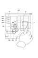
ワーク登録ガイド部27は、入力画面60Cに続いて、図12に示す入力画面60Dをタッチパネル22に表示する。入力画面60Dは、特徴部C1の形状・大きさ及びワークW内における特徴部C1の位置を入力するための画面であり、入力画面60Bと同様のワーク表示部61、フロー表示部62、ズームボタン63、確定ボタン65及び描画ツール66を含む。ワーク登録ガイド部27は、入力画面60Dにおいても表示枠62cをハイライト表示する。なお、図12におけるワークWは、図11におけるワークWに比べ、ズームボタン63により拡大されている。 Following the
入力画面60Dにおいても、特定点指定ボタン66a,66bにより特定点を指定できる。ワーク登録ガイド部27は、指定された特定点に基づいて、特徴部C1の周縁に倣う特徴部包囲図形R2を、ワークWの画像に重ねてワーク表示部61に描画する。調整ボタン66c,66d,66e,66fにより特定点の位置を調整することで、特徴部包囲図形R2を特徴部C1の周縁に更に近付けることができる。 Also on the
入力画面60Dに促され、ユーザが特徴部包囲図形R2を描画し、確定ボタン65に触れると、特徴部包囲図形R2の形状・大きさが、特徴部C1の形状・大きさとしてワーク登録ガイド部27に取得される。また、ワーク包囲図形R1内における特徴部包囲図形R2の位置が、ワークW内における特徴部C1の位置としてワーク登録ガイド部27に取得される。なお、ワーク登録ガイド部27は、入力画面60Dへの入力を促すために、特定点指定ボタン66a,66b、調整ボタン66c,66d,66e,66f及び確定ボタン65をそれぞれハイライト表示してもよい。 When prompted by the
次に、画像処理装置U1は、図3に示すように、基準点情報を取得する(S21)。基準点情報の取得に際して、ワーク登録ガイド部27は、図13に示す入力画面60Eをタッチパネル22に表示する。 Next, the image processing apparatus U1 acquires reference point information as shown in FIG. 3 (S21). When acquiring the reference point information, the work
入力画面60Eは、ワークW内における基準点の位置を入力するための画面であり、入力画面60Bと同様のワーク表示部61、フロー表示部62、ズームボタン63及び確定ボタン65を含むのに加え、描画ツール67を含む。フロー表示部62において、基準点情報の入力に対応するのは、表示枠62dである。ワーク登録ガイド部27は、入力画面60Eにおいては表示枠62dをハイライト表示する。 The
描画ツール67は、候補点指定ボタン67aと、調整ボタン67b,67c,67d,67eとを含む。候補点指定ボタン67aは、基準点の候補となる点を入力するためのボタンである。候補点指定ボタン67aに触れると、ワーク表示部61において基準点の候補点を指定することが可能となる。ワーク登録ガイド部27は、指定された候補点P1を、ワークWの画像に重ねてワーク表示部61に描画する。 The
調整ボタン67b,67c,67d,67eは、候補点を上下左右にずらすボタンである。調整ボタン67b,67c,67d,67eにより、候補点を目標の位置に近付けることができる。 The
入力画面60Eに促され、ユーザが候補点P1を描画し、確定ボタン65に触れると、ワーク包囲図形R1内における候補点P1の位置が、ワークW内における基準点の位置として、ワーク登録ガイド部27に取得される。なお、ワーク登録ガイド部27は、入力画面60Eへの入力を促すために、候補点指定ボタン67a、調整ボタン67b,67c,67d,67e及び確定ボタン65をそれぞれハイライト表示してもよい。 When the user draws the candidate point P1 and touches the
次に、画像処理装置U1は、図3に示すように、ワークWの画像認識プログラムを登録する(S22)。画像認識プログラムの登録に際して、ワーク登録ガイド部27は、図14に示す入力画面60Fをタッチパネル22に表示する。 Next, the image processing apparatus U1 registers an image recognition program for the workpiece W as shown in FIG. 3 (S22). When registering the image recognition program, the work
入力画面60Fは、入力画面60Aと同様のワーク表示部61、フロー表示部62、ズームボタン63及び確定ボタン65を含むのに加え、完了ボタン68を含む。完了ボタン68は、パラメータ入力を完了させるボタンである。完了ボタン68は、フロー表示部62の表示枠62dに連なっている。直前の工程を示す表示枠62dに連なっているので、完了ボタン68はユーザにより視認され易い。 The
入力画面60Fに促され、ユーザが完了ボタン68に触れると、登録部28は、ワーク登録ガイド部27が取得した上記パラメータを、第2記憶部26のベースプログラムにあてはめることで、画像認識プログラムを構築し、第1記憶部23に登録する。以上でワークWの画像認識プログラムの登録が完了する。なお、ワーク登録ガイド部27は、入力画面60Fへの入力を促すために、完了ボタン68をハイライト表示してもよい。 When prompted by the
以上に説明したロボットシステム1によれば、ワーク登録ガイド部27が取得したパラメータが第2記憶部26のベースプログラムにあてはめられて画像認識プログラムが構築され、第1記憶部23に登録される。このため、ロボットシステム1のユーザは、パラメータを入力するのみで画像認識プログラムを登録できる。 According to the robot system 1 described above, the parameters acquired by the work
パラメータの入力に際しては、ワーク登録ガイド部27により、パラメータの入力を促す複数の入力画面60A〜60Eが一画面ずつタッチパネル22に表示され、一つの入力画面におけるパラメータの入力が完了する度に次の入力画面に切り替えられる。このため、ユーザは、入力画面60A〜60Eに従った入力操作を行うのみで、パラメータを漏れなく入力できる。従って、ワークWの画像認識プログラムを容易に登録できる。 When inputting parameters, the work
ユーザは、入力画面60A,60Bに従ってワーク包囲図形R1を描画することで、ワークWの外形・大きさを入力できる。描画中のワーク包囲図形R1はワークWの画像に重ねて表示されるので、ワークWの画像に合わせて形状・大きさを調節して容易にワーク包囲図形R1を描画できる。従って、ワークWの外形・大きさを容易に入力でき、ワークWの画像認識プログラムを更に容易に登録できる。 The user can input the outer shape and size of the workpiece W by drawing the workpiece surrounding figure R1 according to the input screens 60A and 60B. Since the workpiece surrounding figure R1 being drawn is displayed so as to be superimposed on the image of the workpiece W, the workpiece surrounding figure R1 can be easily drawn by adjusting the shape and size according to the image of the workpiece W. Therefore, the outer shape and size of the workpiece W can be easily input, and the image recognition program for the workpiece W can be registered more easily.
ユーザは、入力画面60C,60Dに従って特徴部包囲図形を描画することで、特徴部C1の形状・大きさ及びワーク内における特徴部C1の位置を入力できる。描画中の特徴部包囲図形R2はワークWの画像に重ねて表示されるので、特徴部C1の画像に合わせて形状を調節して容易に特徴部包囲図形R2を描画できる。従って、特徴部C1の形状・大きさ及びワークW内における特徴部C1の位置を容易に入力でき、ワークWの画像認識プログラムを更に容易に登録できる。 The user can input the shape / size of the feature portion C1 and the position of the feature portion C1 in the work by drawing the feature portion surrounding figure in accordance with the input screens 60C and 60D. Since the feature enclosing figure R2 being drawn is displayed so as to be superimposed on the image of the workpiece W, the feature enclosing figure R2 can be easily drawn by adjusting the shape according to the image of the feature C1. Accordingly, the shape / size of the feature C1 and the position of the feature C1 in the workpiece W can be easily input, and the image recognition program for the workpiece W can be registered more easily.
ユーザは、入力画面60Eに従って基準点の候補点を指示するのみで、基準点のワークW内における位置を入力できる。候補点P1はワークWの画像に重ねて表示されるので、ワークWの画像に合わせて位置を調節して容易に候補点P1を指示できる。従って、基準点のワークW内における位置を容易に入力でき、ワークWの画像認識プログラムを更に容易に登録できる。 The user can input the position of the reference point in the workpiece W only by designating the reference point candidate point according to the
ロボットシステム1は、ロボットアーム10の動作許可状態と動作禁止状態とを切り替えるスイッチ21aを更に備え、画像処理装置U1は、スイッチ21aがロボットアーム10を動作許可状態としているときに、タッチパネル22を入力拒否状態とし、スイッチ21aがロボットアーム10を動作禁止状態としているときに、タッチパネル22を入力許可状態とする。このため、ワークWの画像認識プログラムをより安全に登録できる。 The robot system 1 further includes a
以上、本発明の好適な実施形態について説明してきたが、本発明は必ずしも上述した実施形態に限定されるものではなく、その要旨を逸脱しない範囲で様々な変更が可能である。ロボットコントローラ20は、必ずしも図示のように一体化されていなくてもよく、例えばロボットアーム10の制御ユニットと、画像処理ユニットと、これらのユニットを繋ぐプログラマブルロジックコントローラ(PLC)とに分離されていてもよい。この場合、画像処理ユニットが画像処理装置U1を構成する。 The preferred embodiments of the present invention have been described above. However, the present invention is not necessarily limited to the above-described embodiments, and various modifications can be made without departing from the scope of the present invention. The
1…ロボットシステム、10…ロボットアーム、21a…スイッチ、22…タッチパネル、26…記憶部、27…ワーク登録ガイド部、28…登録部、40…カメラ、60A,60B,60C,60D,60E…入力画面、66,67…描画ツール、C1…特徴部、P1…候補点、R1…ワーク包囲図形、R2…特徴部包囲図形、U1…画像処理装置、W…ワーク。 DESCRIPTION OF SYMBOLS 1 ... Robot system, 10 ... Robot arm, 21a ... Switch, 22 ... Touch panel, 26 ... Memory | storage part, 27 ... Work registration guide part, 28 ... Registration part, 40 ... Camera, 60A, 60B, 60C, 60D, 60E ... Input Screen, 66, 67 ... Drawing tool, C1 ... Feature part, P1 ... Candidate point, R1 ... Work surrounding figure, R2 ... Feature part surrounding figure, U1 ... Image processing device, W ... Workpiece.
Claims (5)
Translated fromJapaneseワークの撮影用に設置されたカメラと、
タッチパネルと、
前記カメラにより撮影された画像から、画像認識プログラムに従って前記ワークを認識する画像処理装置と、を備え、
前記画像処理装置は、
前記ワークに関する複数のパラメータの入力により、前記画像認識プログラムとなるベースプログラムの記憶部と、
前記パラメータの入力を促す複数の入力画面を一画面ずつ前記タッチパネルに表示し、一つの前記入力画面における前記パラメータの入力が完了する度に次の前記入力画面に切り替えることで全ての前記パラメータをタッチパネルから順次取得するワーク登録ガイド部と、
前記ワーク登録ガイド部が取得した前記パラメータを前記記憶部の前記ベースプログラムにあてはめることで前記画像認識プログラムを構築し、登録する登録部と、を有するロボットシステム。A robot arm,
A camera installed for shooting workpieces,
A touch panel;
An image processing device for recognizing the workpiece according to an image recognition program from an image photographed by the camera,
The image processing apparatus includes:
By inputting a plurality of parameters related to the workpiece, a storage unit of a base program that becomes the image recognition program,
A plurality of input screens for prompting the input of the parameters are displayed on the touch panel one screen at a time, and every time the input of the parameters on one input screen is completed, all the parameters are switched to the next touch screen Work registration guide part that is acquired sequentially from
A robot system comprising: a registration unit that constructs and registers the image recognition program by applying the parameter acquired by the work registration guide unit to the base program of the storage unit.
前記ワーク登録ガイド部は、前記カメラにより撮影された前記ワークの画像と、前記ワークの周縁に倣うワーク包囲図形の描画ツールとを含む画面を、前記入力画面として前記タッチパネルに表示し、
描画中の前記ワーク包囲図形を前記ワークの画像に重ねて前記タッチパネルに表示し、
前記ワーク包囲図形の形状・大きさを前記ワークの外形・大きさとして取得する、請求項1記載のロボットシステム。The parameter includes the outer shape / size of the workpiece,
The work registration guide unit displays on the touch panel as the input screen a screen including an image of the work photographed by the camera and a drawing tool for a work surrounding figure following the periphery of the work,
The work surrounding figure being drawn is superimposed on the image of the work and displayed on the touch panel,
The robot system according to claim 1, wherein the shape and size of the workpiece surrounding figure are acquired as the outer shape and size of the workpiece.
前記ワーク登録ガイド部は、前記カメラにより撮影された前記ワークの画像と、前記特徴部の周縁に倣う特徴部包囲図形の描画ツールとを含む画面を、前記入力画面として前記タッチパネルに表示し、
描画中の前記特徴部包囲図形を前記ワークの画像に重ねて前記タッチパネルに表示し、
前記特徴部包囲図形の形状・大きさを前記特徴部の形状・大きさとして取得し、前記ワーク包囲図形内における前記特徴部包囲図形の位置を前記ワーク内における前記特徴部の位置として取得する、請求項2記載のロボットシステム。The parameter further includes the shape / size of the characteristic part for specifying the orientation of the work and the position of the characteristic part in the work,
The work registration guide unit displays a screen including an image of the work photographed by the camera and a drawing tool for a feature encircling figure following the periphery of the feature as the input screen on the touch panel,
The feature enclosing figure being drawn is superimposed on the image of the work and displayed on the touch panel,
Obtaining the shape / size of the feature enclosing figure as the shape / size of the feature, and obtaining the position of the feature enclosing figure in the work enclosing figure as the position of the feature in the work; The robot system according to claim 2.
前記ワーク登録ガイド部は、前記カメラにより撮影された前記ワークの画像と、前記基準点の候補点の描画ツールとを含む画面を、前記入力画面として前記タッチパネルに表示し、
前記候補点を前記ワークの画像に重ねて前記タッチパネルに表示し、
前記ワーク包囲図形内における前記候補点の位置を前記ワーク内での前記基準点の位置として取得する、請求項2又は3記載のロボットシステム。The parameter further includes a position in the workpiece of a reference point that serves as a reference when the robot arm performs an operation on the workpiece.
The work registration guide unit displays a screen including the image of the work photographed by the camera and a drawing tool for the reference point candidate points on the touch panel as the input screen,
The candidate point is displayed on the touch panel so as to overlap the workpiece image,
The robot system according to claim 2, wherein the position of the candidate point in the workpiece surrounding figure is acquired as the position of the reference point in the workpiece.
前記画像処理装置は、前記スイッチが前記ロボットアームを前記動作許可状態としているときに、前記タッチパネルを入力拒否状態とし、前記スイッチが前記ロボットアームを前記動作禁止状態としているときに、前記タッチパネルを入力許可状態とする、請求項1〜4のいずれか一項記載のロボットシステム。A switch for switching between an operation permission state and an operation prohibition state of the robot arm;
The image processing apparatus inputs the touch panel when the switch sets the robot arm to the operation-permitted state and sets the touch panel to an input rejection state, and when the switch sets the robot arm to the operation-disabled state. The robot system according to any one of claims 1 to 4, wherein the robot system is allowed.
Priority Applications (4)
| Application Number | Priority Date | Filing Date | Title |
|---|---|---|---|
| JP2013056649AJP5672326B2 (en) | 2013-03-19 | 2013-03-19 | Robot system |
| CN201410049196.3ACN104057455A (en) | 2013-03-19 | 2014-02-12 | Robot system |
| EP20140159951EP2782049A3 (en) | 2013-03-19 | 2014-03-14 | Robot system and image processing method |
| US14/218,979US20140286565A1 (en) | 2013-03-19 | 2014-03-19 | Robot system and image processing method |
Applications Claiming Priority (1)
| Application Number | Priority Date | Filing Date | Title |
|---|---|---|---|
| JP2013056649AJP5672326B2 (en) | 2013-03-19 | 2013-03-19 | Robot system |
Publications (2)
| Publication Number | Publication Date |
|---|---|
| JP2014180722A JP2014180722A (en) | 2014-09-29 |
| JP5672326B2true JP5672326B2 (en) | 2015-02-18 |
Family
ID=50287927
Family Applications (1)
| Application Number | Title | Priority Date | Filing Date |
|---|---|---|---|
| JP2013056649AExpired - Fee RelatedJP5672326B2 (en) | 2013-03-19 | 2013-03-19 | Robot system |
Country Status (4)
| Country | Link |
|---|---|
| US (1) | US20140286565A1 (en) |
| EP (1) | EP2782049A3 (en) |
| JP (1) | JP5672326B2 (en) |
| CN (1) | CN104057455A (en) |
Families Citing this family (10)
| Publication number | Priority date | Publication date | Assignee | Title |
|---|---|---|---|---|
| JP6494313B2 (en)* | 2015-02-09 | 2019-04-03 | キヤノン株式会社 | Image processing method, apparatus system, program, and storage medium |
| WO2016154995A1 (en) | 2015-04-02 | 2016-10-06 | Abb Technology Ltd | Method for industrial robot commissioning, industrial robot system and control system using the same |
| JP6514041B2 (en)* | 2015-06-02 | 2019-05-15 | 株式会社ミツトヨ | Control method of shape measuring device |
| CN104959990B (en)* | 2015-07-09 | 2017-03-15 | 江苏省电力公司连云港供电公司 | A kind of distribution maintenance manipulator arm and its method |
| JP6333871B2 (en)* | 2016-02-25 | 2018-05-30 | ファナック株式会社 | Image processing apparatus for displaying an object detected from an input image |
| JP6356722B2 (en)* | 2016-04-07 | 2018-07-11 | ファナック株式会社 | A numerical controller that improves production processes. |
| US10624738B2 (en)* | 2017-02-23 | 2020-04-21 | Edwards Lifesciences Corporation | Heart valve manufacturing devices and methods |
| JP6812325B2 (en)* | 2017-10-26 | 2021-01-13 | 株式会社日立ビルシステム | Robot management system |
| US10853524B2 (en)* | 2018-01-23 | 2020-12-01 | Wipro Limited | System and method for providing security for robots |
| WO2019210162A1 (en)* | 2018-04-26 | 2019-10-31 | Walmart Apollo, Llc | Systems and methods autonomously performing instructed operations using a robotic device |
Family Cites Families (11)
| Publication number | Priority date | Publication date | Assignee | Title |
|---|---|---|---|---|
| JP3529158B2 (en)* | 1994-05-18 | 2004-05-24 | ファナック株式会社 | Robot operation programming method and programming device |
| JP2000135689A (en)* | 1998-10-30 | 2000-05-16 | Fanuc Ltd | Image processor for robot |
| JP2007523757A (en)* | 2003-06-20 | 2007-08-23 | ファナック ロボティクス アメリカ,インコーポレイティド | Tracking and mirroring of multiple robot arms |
| JP3946753B2 (en)* | 2005-07-25 | 2007-07-18 | ファナック株式会社 | Robot program evaluation / correction method and robot program evaluation / correction device |
| CA2644614C (en)* | 2006-03-03 | 2015-02-03 | Syddansk Universitet | Programmable robot and user interface |
| FR2898824B1 (en)* | 2006-03-27 | 2009-02-13 | Commissariat Energie Atomique | INTELLIGENT INTERFACE DEVICE FOR ENTRYING AN OBJECT BY A MANIPULATOR ROBOT AND METHOD OF IMPLEMENTING SAID DEVICE |
| JP2007334678A (en)* | 2006-06-15 | 2007-12-27 | Fanuc Ltd | Robot simulation device |
| JP2008021092A (en)* | 2006-07-12 | 2008-01-31 | Fanuc Ltd | Simulation apparatus of robot system |
| JP5458616B2 (en)* | 2009-03-19 | 2014-04-02 | 株式会社デンソーウェーブ | Robot control command input device |
| JP2010243317A (en)* | 2009-04-06 | 2010-10-28 | Seiko Epson Corp | Object recognition method |
| US8781629B2 (en)* | 2010-09-22 | 2014-07-15 | Toyota Motor Engineering & Manufacturing North America, Inc. | Human-robot interface apparatuses and methods of controlling robots |
- 2013
- 2013-03-19JPJP2013056649Apatent/JP5672326B2/ennot_activeExpired - Fee Related
- 2014
- 2014-02-12CNCN201410049196.3Apatent/CN104057455A/enactivePending
- 2014-03-14EPEP20140159951patent/EP2782049A3/ennot_activeWithdrawn
- 2014-03-19USUS14/218,979patent/US20140286565A1/ennot_activeAbandoned
Also Published As
| Publication number | Publication date |
|---|---|
| EP2782049A3 (en) | 2015-05-06 |
| EP2782049A2 (en) | 2014-09-24 |
| US20140286565A1 (en) | 2014-09-25 |
| JP2014180722A (en) | 2014-09-29 |
| CN104057455A (en) | 2014-09-24 |
Similar Documents
| Publication | Publication Date | Title |
|---|---|---|
| JP5672326B2 (en) | Robot system | |
| KR100762380B1 (en) | Motion control apparatus for teaching robot position, robot-position teaching apparatus, motion control method for teaching robot position, robot-position teaching method, and motion control program for teaching robot-position | |
| JP6763846B2 (en) | Teaching device and teaching method for teaching robots | |
| JP6343353B2 (en) | Robot motion program generation method and robot motion program generation device | |
| JP6843051B2 (en) | Remote control robot system | |
| JP4167940B2 (en) | Robot system | |
| US20190202058A1 (en) | Method of programming an industrial robot | |
| JP6221224B2 (en) | Robot system, program, production system and robot | |
| JP2000135689A (en) | Image processor for robot | |
| CN112446287B (en) | Electronic device, method and storage medium for setting control process of device | |
| JP2020082273A (en) | Image processing device, control method thereof, and program | |
| JP2003065713A (en) | Program and part program creating device for image measuring apparatus | |
| JP2004005639A (en) | Monitoring device | |
| JP2018034241A (en) | Robot, robot control device, and robot system | |
| JP7553612B2 (en) | Teaching Device | |
| JP3397544B2 (en) | Camera control device, display device, and display method | |
| TW202315722A (en) | Teaching device and robot system | |
| JP2022123241A (en) | Image processing device, image processing method, production system, article manufacturing method, and computer program, | |
| WO2014091897A1 (en) | Robot control system | |
| JP2011141584A (en) | Input control equipment | |
| JP2020123049A (en) | Dimension unit setting method, information processing device, and robot system | |
| US20250026010A1 (en) | Teaching device, control device, and mechanical system | |
| JP7533235B2 (en) | Computer program, method for creating a control program for a robot, and system for executing a process for creating a control program for a robot | |
| US20250128422A1 (en) | Robot system and image capturing method | |
| US20240152117A1 (en) | Cell controller |
Legal Events
| Date | Code | Title | Description |
|---|---|---|---|
| A131 | Notification of reasons for refusal | Free format text:JAPANESE INTERMEDIATE CODE: A131 Effective date:20140902 | |
| TRDD | Decision of grant or rejection written | ||
| A01 | Written decision to grant a patent or to grant a registration (utility model) | Free format text:JAPANESE INTERMEDIATE CODE: A01 Effective date:20141125 | |
| A61 | First payment of annual fees (during grant procedure) | Free format text:JAPANESE INTERMEDIATE CODE: A61 Effective date:20141208 | |
| R150 | Certificate of patent or registration of utility model | Ref document number:5672326 Country of ref document:JP Free format text:JAPANESE INTERMEDIATE CODE: R150 | |
| LAPS | Cancellation because of no payment of annual fees |