JP5667645B2 - Endoscopic steerable structure - Google Patents
Endoscopic steerable structureDownload PDFInfo
- Publication number
- JP5667645B2 JP5667645B2JP2012548467AJP2012548467AJP5667645B2JP 5667645 B2JP5667645 B2JP 5667645B2JP 2012548467 AJP2012548467 AJP 2012548467AJP 2012548467 AJP2012548467 AJP 2012548467AJP 5667645 B2JP5667645 B2JP 5667645B2
- Authority
- JP
- Japan
- Prior art keywords
- elongate body
- actuator
- elongated body
- support
- distal
- Prior art date
- Legal status (The legal status is an assumption and is not a legal conclusion. Google has not performed a legal analysis and makes no representation as to the accuracy of the status listed.)
- Active
Links
- 239000012781shape memory materialSubstances0.000claimsdescription13
- 238000007689inspectionMethods0.000claimsdescription7
- 239000000523sampleSubstances0.000claimsdescription7
- 230000001066destructive effectEffects0.000claimsdescription6
- 238000009659non-destructive testingMethods0.000claimsdescription4
- 239000002184metalSubstances0.000claimsdescription3
- 238000005452bendingMethods0.000description16
- 230000005540biological transmissionEffects0.000description4
- 230000000694effectsEffects0.000description3
- 238000010438heat treatmentMethods0.000description3
- 238000010586diagramMethods0.000description1
- 230000005484gravityEffects0.000description1
- 238000009434installationMethods0.000description1
- 239000000463materialSubstances0.000description1
- 230000003252repetitive effectEffects0.000description1
Images


Classifications
- F—MECHANICAL ENGINEERING; LIGHTING; HEATING; WEAPONS; BLASTING
- F01—MACHINES OR ENGINES IN GENERAL; ENGINE PLANTS IN GENERAL; STEAM ENGINES
- F01D—NON-POSITIVE DISPLACEMENT MACHINES OR ENGINES, e.g. STEAM TURBINES
- F01D21/00—Shutting-down of machines or engines, e.g. in emergency; Regulating, controlling, or safety means not otherwise provided for
- F01D21/003—Arrangements for testing or measuring
- G—PHYSICS
- G01—MEASURING; TESTING
- G01N—INVESTIGATING OR ANALYSING MATERIALS BY DETERMINING THEIR CHEMICAL OR PHYSICAL PROPERTIES
- G01N29/00—Investigating or analysing materials by the use of ultrasonic, sonic or infrasonic waves; Visualisation of the interior of objects by transmitting ultrasonic or sonic waves through the object
- G01N29/22—Details, e.g. general constructional or apparatus details
- G01N29/225—Supports, positioning or alignment in moving situation
- F—MECHANICAL ENGINEERING; LIGHTING; HEATING; WEAPONS; BLASTING
- F05—INDEXING SCHEMES RELATING TO ENGINES OR PUMPS IN VARIOUS SUBCLASSES OF CLASSES F01-F04
- F05D—INDEXING SCHEME FOR ASPECTS RELATING TO NON-POSITIVE-DISPLACEMENT MACHINES OR ENGINES, GAS-TURBINES OR JET-PROPULSION PLANTS
- F05D2260/00—Function
- F05D2260/80—Diagnostics
- Y—GENERAL TAGGING OF NEW TECHNOLOGICAL DEVELOPMENTS; GENERAL TAGGING OF CROSS-SECTIONAL TECHNOLOGIES SPANNING OVER SEVERAL SECTIONS OF THE IPC; TECHNICAL SUBJECTS COVERED BY FORMER USPC CROSS-REFERENCE ART COLLECTIONS [XRACs] AND DIGESTS
- Y10—TECHNICAL SUBJECTS COVERED BY FORMER USPC
- Y10T—TECHNICAL SUBJECTS COVERED BY FORMER US CLASSIFICATION
- Y10T74/00—Machine element or mechanism
- Y10T74/20—Control lever and linkage systems
- Y10T74/20207—Multiple controlling elements for single controlled element
- Y10T74/20305—Robotic arm
- Y10T74/20323—Robotic arm including flaccid drive element
Landscapes
- Engineering & Computer Science (AREA)
- Biochemistry (AREA)
- Immunology (AREA)
- Physics & Mathematics (AREA)
- Health & Medical Sciences (AREA)
- Life Sciences & Earth Sciences (AREA)
- Chemical & Material Sciences (AREA)
- Analytical Chemistry (AREA)
- Mechanical Engineering (AREA)
- General Engineering & Computer Science (AREA)
- General Health & Medical Sciences (AREA)
- General Physics & Mathematics (AREA)
- Pathology (AREA)
- Instruments For Viewing The Inside Of Hollow Bodies (AREA)
- Investigating Or Analyzing Materials By The Use Of Magnetic Means (AREA)
- Endoscopes (AREA)
- Control Of Position Or Direction (AREA)
- Investigating Or Analyzing Materials By The Use Of Ultrasonic Waves (AREA)
- Ultra Sonic Daignosis Equipment (AREA)
Description
Translated fromJapanese本発明は、例えばタービンエンジン等の機械的なシステムの内側を、特に渦電流式または超音波式のセンサによって検査するための可撓かつ操縦可能な構造体に関する。 The present invention relates to a flexible and steerable structure for inspecting the interior of a mechanical system such as a turbine engine, in particular by means of eddy current or ultrasonic sensors.
内視鏡または非破壊検査プローブの支持体などの特定の現在の可撓かつ操縦可能な構造体は、剛性のあるまたは弾性変形可能な長い管の形態であり、そのような管が、特定の位置決め角度を選択するため、および内視鏡またはプローブ支持体の前進をより容易にするために、長手軸に対して操縦可能な端部を有している。 Certain current flexible and steerable structures, such as endoscopes or non-destructive inspection probe supports, are in the form of long tubes that are rigid or elastically deformable, and such tubes It has a steerable end with respect to the longitudinal axis for selecting the positioning angle and for easier advancement of the endoscope or probe support.
内視鏡の特定の領域を適切な様相で湾曲させるために、引っ張り線または実際には形状記憶材料で作られた線などの機械的なアクチュエータを、構造体に沿って配置することがすでに提案されている。これらのアクチュエータが、引っ張りの印加または温度上昇の影響によって短くなり、アクチュエータの位置する領域において内視鏡の曲率の変化を引き起こす。 It has already been proposed to place a mechanical actuator along the structure, such as a pull line or actually a line made of shape memory material, in order to curve certain areas of the endoscope in an appropriate manner Has been. These actuators are shortened by the effect of applying tension or increasing temperature, causing a change in the curvature of the endoscope in the region where the actuator is located.
この形式の装置は、主として幾何学的に複雑な空間または限られた空間における可動性および操縦性に欠けるがゆえに、限界を抱えている。さらに、内視鏡の端部を湾曲させる能力に関しても欠点が存在する。 This type of device is limited because it lacks mobility and maneuverability, mainly in geometrically complex or limited spaces. In addition, there are drawbacks regarding the ability to bend the end of the endoscope.
このような困難を克服するために、本出願の出願人は、仏国特許出願第07/06726号明細書において、装置が曲率の変化を有する外形に達するよう、剛性の高い領域において曲がりの量が小さくなり、剛性の低い領域において曲がりの量が大きくなるように、装置の細長い本体のうちの剛性変化を有する部分にアクチュエータを取り付けることを提案している。 In order to overcome such difficulties, the applicant of the present application has found in French patent application 07/06726 that the amount of bending in the rigid region is such that the device reaches an outline with a change in curvature. It is proposed that the actuator be attached to a portion of the elongated body of the device having a change in rigidity so that the amount of bending is increased in a region having low rigidity.
しかしながら、このような種類の装置または上述の他の種類の装置において得られる曲率は、依然として限られており、それらの使用における選択の自由を制限している。 However, the curvatures obtained in these types of devices or the other types of devices described above are still limited, limiting the freedom of choice in their use.
さらに、タービンエンジンを検査する特定の状況においては、非破壊検査を実行するため、および/またはエンジンの検査を続けながら全体としての装置への重力の影響を抑えるために、エンジンの静止部分への装置の安定かつ確実な取り付けを達成することが、望ましいかもしれない。 Further, in certain situations where turbine engines are inspected, to perform non-destructive inspection and / or to reduce the effects of gravity on the overall device while continuing to inspect the engine, It may be desirable to achieve a stable and reliable installation of the device.
本発明の特定の目的は、これらの問題に対する技術的解決策であって、安価かつ効果的であり、先行技術の欠点の回避を可能にする技術的解決策を提供することにある。 A particular object of the present invention is to provide a technical solution to these problems, which is cheap and effective and allows the avoidance of the disadvantages of the prior art.
この目的のため、本発明は、細長い本体と、この細長い本体の少なくとも一部分の曲率を変化させることができる少なくとも1つのアクチュエータと、を備える非破壊検査用の可撓かつ操縦可能な構造体であって、アクチュエータが、細長い本体に組み合わせられた支持体によって保持され、この支持体は、細長い本体から離れており、または離すことができる遠位部を有しており、この遠位部が、引っ張り線によって細長い本体の一部分に接続されていることを特徴とする構造体を提供する。 For this purpose, the present invention is a flexible and steerable structure for non-destructive testing comprising an elongate body and at least one actuator capable of changing the curvature of at least a portion of the elongate body. The actuator is held by a support associated with the elongate body, the support having a distal portion that is remote from or can be separated from the elongate body, the distal portion being A structure is provided that is connected to a portion of an elongated body by a wire.
先行技術と異なり、本発明は、もはやアクチュエータを細長い本体に沿って配置することを提案せず、むしろアクチュエータを細長い本体から離れた支持体上に組み付けることを提案する。 Unlike the prior art, the present invention no longer suggests placing the actuator along the elongated body, but rather, assembling the actuator on a support remote from the elongated body.
この構成においては、支持体が細長い本体の曲げをより容易にするレバーアームを形成し、曲げが、細長い本体に沿ってではなく、引っ張り線に沿って細長い本体に対して横方向に作用する力によって実行されることで、細長い本体の曲げの量を大きくすることが可能になる。 In this configuration, the support forms a lever arm that makes it easier to bend the elongate body, and the force that the bending acts laterally on the elongate body along the pull line rather than along the elongate body. This makes it possible to increase the amount of bending of the elongated body.
伝達比、すなわち曲げの角度とアクチュエータの長さの減少との間の比が、先行技術における比よりも小さい。これは、細長い本体の曲がった部分について、はるかに正確な位置決めの実現を可能にする。 The transmission ratio, i.e. the ratio between the angle of bending and the reduction in actuator length, is smaller than in the prior art. This makes it possible to achieve a much more accurate positioning for the bent part of the elongated body.
アクチュエータの動作からもたらされる力が、細長い本体により良好に伝達される。この良好な力の伝達は、細長い本体の一部分を曲げて検査対象の三次元構造体の静止部位に押し付けることによって、可撓な構造体の安定な取り付けの達成を可能にする。したがって、細長い本体の遠位端に配置された非破壊検査センサの位置が、非破壊検査の作業の実行時に静止位置にあることを保証することができる。 The force resulting from the operation of the actuator is better transmitted by the elongated body. This good force transmission makes it possible to achieve a stable attachment of the flexible structure by bending a portion of the elongated body and pressing it against the stationary part of the three-dimensional structure to be examined. Thus, it can be ensured that the position of the non-destructive inspection sensor located at the distal end of the elongate body is in a stationary position when performing a non-destructive inspection operation.
したがって、航空機産業において、本発明は、タービンエンジンについて、これまではエンジンを分解しなければアクセスすることができなかった領域を検査できるようにし、停止時間およびコストの削減に貢献する。 Accordingly, in the aircraft industry, the present invention allows turbine engines to be inspected in areas that could not previously be accessed without disassembling the engine, contributing to reduced downtime and costs.
本発明の他の特徴によれば、アクチュエータが形状記憶材料で作られる。 According to another feature of the invention, the actuator is made of a shape memory material.
変形形態においては、アクチュエータが、機械式であってもよく、細長い本体の引っ張り線に直接接続されたケーブルを備えることができ、このケーブルを、支持体の遠位部に沿って延ばすことができる。 In a variant, the actuator may be mechanical and may comprise a cable connected directly to the elongate body pull line, which cable may extend along the distal part of the support. .
支持体の遠位部は、剛体であってもよく、そのような状況のもとでは、アクチュエータが上述のようなケーブルであってもよい。 The distal portion of the support may be rigid and, under such circumstances, the actuator may be a cable as described above.
変形形態においては、支持体の遠位部が変形可能であってもよく、そのような状況のもとでは、アクチュエータが、収縮時に支持体の遠位部を変形させて細長い本体に接続された線に引っ張りを生じさせる形状記憶材料を備えることができる。 In a variant, the distal part of the support may be deformable, and under such circumstances, the actuator is connected to the elongate body by deforming the distal part of the support when contracted. A shape memory material can be provided that causes the wire to pull.
本発明の一実施形態においては、細長い本体の引っ張り線が、枢支点を形成すべく検査対象の構造体の静止要素に点接触または準点接触にて押し付けられる領域において、細長い本体の遠位端から離れた位置で細長い本体に接続される。 In one embodiment of the invention, the distal end of the elongate body in the region where the pull line of the elongate body is pressed in point or quasi-point contact with the stationary element of the structure under examination to form a pivot point. Connected to the elongate body at a position remote from.
枢支点は、細長い本体の遠位端と引っ張り線の細長い本体への接続点との間に位置する。結果として、細長い本体の遠位端に角度的走査を実行させることが可能であり、検査対象の構造体の内側の特定の角度範囲を連続的なやり方で観察することが望まれる場合に有用となりうる。 The pivot point is located between the distal end of the elongated body and the point of connection of the pull line to the elongated body. As a result, it is possible to cause the distal end of the elongate body to perform an angular scan, which is useful when it is desired to observe a specific angular range inside the structure to be examined in a continuous manner. sell.
変形形態においては、引っ張り線が、細長い本体の遠位端または前記遠位端の近傍に接続される。 In a variation, the pull line is connected to or near the distal end of the elongate body.
好都合には、細長い本体の遠位端に取り付けられた非破壊検査手段が、例えば渦電流プローブまたは超音波プローブによって構成される。 Conveniently, the non-destructive inspection means attached to the distal end of the elongated body is constituted by an eddy current probe or an ultrasonic probe, for example.
本発明の現実的な実施形態においては、引っ張り線が金属線である。 In a practical embodiment of the invention, the pull wire is a metal wire.
細長い本体は、細長い本体のさらなる曲がりをもたらすために、少なくとも1つの部位において、機械式または形状記憶材料式の少なくとも1つのアクチュエータをさらに含むことができる。Elongated body, in order to provide further bending of the elongate body,at least one site, can further compriseat least oneactuator of the mechanical or shape memory material type.
あくまでも本発明を限定するものではない例として添付の図面を参照して行なわれる以下の詳細な説明を検討することによって、本発明をよりよく理解することができ、本発明の他の詳細、利点、および特徴が明らかになる。 The present invention may be better understood by studying the following detailed description, given with reference to the accompanying drawings by way of example only, which is not intended to limit the present invention, and other details and advantages of the present invention. , And the characteristics become clear.
最初に、先行技術の非破壊検査のための可撓かつ操縦可能な構造体10を示している図1を参照すると、構造体が、形状記憶材料からなるアクチュエータ14が取り付けられた細長い本体12を備えており、アクチュエータ14は、細長い本体12に沿って細長い本体12の内側に配置されている。例として、アクチュエータ14は、電源手段に接続された線の形態であり、電源手段によって線をジュール効果によって加熱することができる。線14の加熱が、線14の収縮を生じさせ、細長い本体12の曲がりを生じさせる。 Referring first to FIG. 1, which shows a flexible and
図2は、アクチュエータが細長い本体12に沿って細長い本体12の遠位端まで延びている金属線16である点を除き、図1の操縦可能かつ可撓な構造体と同様の操縦可能かつ可撓な構造体15を示している。線16は、細長い本体12に固定された複数の中空ガイド18によって細長い本体12に沿って保持されている。この形式の制御構造において、線16の近位端に加えられる引っ張り(矢印A)により、細長い本体12の遠位端が曲がる。 2 is steerable and possible similar to the steerable and flexible structure of FIG. 1 except that the actuator is a
これらの構造体10および15は、細長い本体12の曲がりの部分を大きな角度に曲げることまたは正確に位置決めすることを、可能にしていない。さらに、詳しく上述した理由により、検査用の構造体を近傍の検査対象の機械的な構造体の静止部分に安定かつ固定的な様相にて取り付けることを、可能にしていない。 These
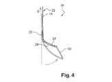
本発明は、可撓かつ操縦可能な構造体20に支持体22を組み合わせることを提案し、この支持体22が、細長い本体26から離れた遠位部または細長い本体26から離すことができる遠位部24を有しており、この遠位部24がアクチュエータ28を保持しており、この遠位部24が引っ張り線30によって細長い本体26に接続される。 The present invention proposes to combine a
図3および図4に示されている本発明の実施形態においては、遠位部24が剛体である。アクチュエータ28は、支持体22に固定された中空ガイド18において支持体22に沿って延びるケーブルである。支持体22の遠位部24の端部において、アクチュエータ28は、細長い本体26の遠位端に接続された引っ張り線30に直接接続されている。 In the embodiment of the invention shown in FIGS. 3 and 4, the
ケーブル28の近位端に加えられる引っ張り(矢印B)によって、細長い本体26の遠位端が曲がるが、この動作の際に支持体22は静止したままである(図4)。 A pull (arrow B) applied to the proximal end of the
図5および図6に示されている本発明の別の実施形態においては、可撓かつ操縦可能な構造体32が、変形可能な支持体22の遠位部36に組み込まれた形状記憶材料からなる線の形態のアクチュエータ34を備えている。遠位部36が、引っ張り線30によって細長い本体26に接続されている。 In another embodiment of the present invention shown in FIGS. 5 and 6, a flexible and
形状記憶材料からなる線を加熱することで、線が収縮し、結果として支持体22の遠位部36が曲がり、したがって細長い本体26が曲がる(図6)。 Heating the line of shape memory material causes the line to contract, resulting in bending of the
上述の2つの実施形態において、細長い本体26を弾性変形可能な材料で製作することで、引っ張りケーブル28が緩められ、または形状記憶材料からなる線34の加熱が止められたときに、休止位置(図3および図5)への復帰を可能にすることができる。 In the two embodiments described above, the
支持体22の遠位部24、36が、細長い本体26を曲げるためのレバーアームを構成し、先行技術よりも小さい伝達比(すなわち、曲げの角度をアクチュエータの長さの減少で割ったもの)ゆえに、細長い本体26の曲がった部分を正確に位置させることを可能にする。したがって、細長い本体26の所与の曲げ角度について、アクチュエータ28、34の長さを先行技術よりも大きく減少させる必要がある。 The
図7は、互いに離れて位置する2つの壁40および42を有している検査対象の構造体38の軸方向断面図であり、壁40および42が、本発明の可撓かつ操縦可能な構造体を通すための2つの開口44および46を備えている。 FIG. 7 is an axial cross-sectional view of a
この図に示されている構成においては、引っ張り線30が、細長い本体26の遠位端に接続されている。細長い本体26が、2つの開口44および46を通って挿入され、支持体22が、遠位部48が2つの壁40および42の間に位置するように第1の開口に挿入されている。遠位部48のアクチュエータを制御することによって、細長い本体26が曲げられ、細長い本体26の遠位端50が第2の開口の縁に当接させられる。さらに、引っ張り線30のうちの細長い本体のすぐ近くの部位が、細長い本体26の曲げの際に第2の開口46の内表面に押し付けられる。 In the configuration shown in this figure, a
このようにして、細長い本体26が、第2の壁42に対して静止かつ安定な様相に配置される。この配置の安定性は、離れて位置する遠位部48から細長い本体26に横方向に加えられる圧力の増大によって高められる。引っ張り線30によるアクチュエータからの力のこの伝達は、曲がりが少なく、好ましくは30°未満であるときにきわめて大きい。 In this way, the
図8が、図7の構造体と同様の検査対象の構造体38を示している。引っ張り線30が、細長い本体26の遠位端54から距離dの位置で細長い本体26に接続されている。細長い本体26が、曲がりの際に端部52が点接触またはほぼ点接触にて第2の開口の縁に押し付けられるような様相で、第2の開口46の内側に挿入されている(図8)。FIG. 8 shows a
この構成は、細長い本体26の遠位端54と引っ張り線30の細長い本体26への接続点56との間の枢支点53の確立を可能にする。 This configuration allows the establishment of a
細長い本体26が弾性変形可能である場合、支持体22の遠位端48に保持されたアクチュエータの繰り返しの動作によって、細長い本体26の遠位端が角度的走査を実行することができる。 If the
角度的走査を実行可能にするアクチュエータは、ケーブルなどの機械式のアクチュエータが使用される場合に、細長い本体の最初の曲げ(図8)に使用されるアクチュエータと同じアクチュエータであってもよいため、引っ張りを加え続けることで細長い本体26の遠位端の枢動が生じる。最初の曲げ(図8)が形状記憶材料からなる線を使用して実行される場合、やはり形状記憶材料で作られる第2の線を支持体22の遠位部48に組み込むことができ、この第2の線の繰り返しの動作によって、細長い本体26の遠位端54に角度的走査を実行させることができる。 The actuator that enables the angular scan may be the same actuator that is used for the initial bending of the elongated body (FIG. 8) when a mechanical actuator such as a cable is used, Continued pulling causes the distal end of the
可撓かつ操縦可能な構造体20、32は、図7および図8に示した種類の機械的な構造体に、最初に湾曲していない細長い本体26を第1および第2の開口44および46を通って挿入することによって係合させられる。支持体22も、枢動およびその後の平行移動によって第1の開口44を通って挿入され、次いで引っ張り線30に張力が加えられることで、構造体20、32が図3および図5に示されるとおりの準備完了位置となる。 The flexible and
非破壊検査手段(図示せず)を、細長い本体26の遠位端に取り付けることができる。例として、そのような手段は、渦電流プローブまたは超音波プローブであってもよい。 Non-destructive testing means (not shown) can be attached to the distal end of the
本発明の他の変種においては、可撓な構造体20、32が、細長い本体26に組み込まれた少なくとも1つの機械式のアクチュエータ16または形状記憶材料アクチュエータ14を備える。 In other variations of the present invention, the
Claims (10)
Translated fromJapanese細長い本体(26)と、
細長い本体(26)の少なくとも一部分の曲率を変化させることができる少なくとも1つのアクチュエータ(28、34)と
を備えている、非破壊検査用の可撓かつ操縦可能な構造体(20、32)であって、
少なくとも1つのアクチュエータ(28、34)が、細長い本体(26)に組み合わせられた前記支持体(22)によって保持され、前記支持体(22)は、遠位部(24、36、48)を有し、
当該遠位部(24、36、48)が、
細長い本体(26)から離れているか、または細長い本体(26)から離すことができ、細長い本体の湾曲が、当該細長い本体(26)に対し、空間的に離れた遠位部(48)から横方向に印加される力によって達成され、さらに、
引っ張り線(30)によって細長い本体(26)の一部分に接続され、
アクチュエータは、支持体および引っ張り線のいずれとも異なることを特徴とする、構造体。A support (22);
An elongated body (26);
A flexible and steerable structure (20, 32) for non-destructive testing comprising at least one actuator (28, 34) capable of changing the curvature of at least a portion of the elongated body (26). There,
Yesat least one actuator (28, 34) is held by an elongate bodythe support which is combined with (26) (22),said support(22), adistal portion (24,36, 48)And
The distal part (24, 36, 48 ) is
The elongate body (26) can be remote from the elongate body (26) or the elongate body can be curved with respect to the elongate body (26) laterally away from the distal portion (48) that is spatially separated. Achieved by a force applied in the direction, and
Connected to a portion of the elongated body (26) by a pull wire (30);
The structure is characterized in that theactuator is different from both the support and the tension line .
Applications Claiming Priority (3)
| Application Number | Priority Date | Filing Date | Title |
|---|---|---|---|
| FR1000139AFR2955177B1 (en) | 2010-01-14 | 2010-01-14 | GUIDED STRUCTURE OF THE ENDOSCOPE TYPE |
| FR1000139 | 2010-01-14 | ||
| PCT/FR2011/050054WO2011086324A2 (en) | 2010-01-14 | 2011-01-12 | Endoscope-like adjustable structure |
Publications (2)
| Publication Number | Publication Date |
|---|---|
| JP2013517522A JP2013517522A (en) | 2013-05-16 |
| JP5667645B2true JP5667645B2 (en) | 2015-02-12 |
Family
ID=43034485
Family Applications (1)
| Application Number | Title | Priority Date | Filing Date |
|---|---|---|---|
| JP2012548467AActiveJP5667645B2 (en) | 2010-01-14 | 2011-01-12 | Endoscopic steerable structure |
Country Status (9)
| Country | Link |
|---|---|
| US (1) | US8844399B2 (en) |
| EP (1) | EP2524113B1 (en) |
| JP (1) | JP5667645B2 (en) |
| CN (1) | CN102713163B (en) |
| BR (1) | BR112012016404B1 (en) |
| CA (1) | CA2786240C (en) |
| FR (1) | FR2955177B1 (en) |
| RU (1) | RU2557947C2 (en) |
| WO (1) | WO2011086324A2 (en) |
Families Citing this family (6)
| Publication number | Priority date | Publication date | Assignee | Title |
|---|---|---|---|---|
| FR2947911B1 (en)* | 2009-07-09 | 2011-06-17 | Snecma | DEVICE FOR CONTROLLING A TURBOMACHINE ENGINE |
| US9625286B2 (en)* | 2015-01-09 | 2017-04-18 | Olympus Scientific Solutions Americas Inc. | Adjustable probe holder assembly for an inspection sensor |
| CN107932507A (en)* | 2017-11-16 | 2018-04-20 | 飞依诺科技(苏州)有限公司 | Ultrasound Instrument mechanical arm and its control method |
| CN113442148A (en)* | 2021-07-07 | 2021-09-28 | 重庆七腾科技有限公司 | Multi-dimensional adjustable manipulator |
| DE102021214239A1 (en) | 2021-12-13 | 2023-06-15 | Robert Bosch Gesellschaft mit beschränkter Haftung | Endoscope device for non-destructive material testing using magnetic testing methods |
| CN114938937B (en)* | 2022-05-18 | 2024-03-08 | 湖南省华芯医疗器械有限公司 | Haulage rope pretension structure, endoscope handle and endoscope |
Family Cites Families (17)
| Publication number | Priority date | Publication date | Assignee | Title |
|---|---|---|---|---|
| FR706726A (en) | 1930-11-29 | 1931-06-29 | Climax Motorenwerke Und Schiff | Exhaust for internal combustion engines |
| US4930494A (en)* | 1988-03-09 | 1990-06-05 | Olympus Optical Co., Ltd. | Apparatus for bending an insertion section of an endoscope using a shape memory alloy |
| US5531664A (en)* | 1990-12-26 | 1996-07-02 | Olympus Optical Co., Ltd. | Bending actuator having a coil sheath with a fixed distal end and a free proximal end |
| JPH0520705U (en)* | 1991-09-03 | 1993-03-19 | 住友電気工業株式会社 | Endoscope |
| RU2057488C1 (en)* | 1992-12-07 | 1996-04-10 | Научно-внедренческая производственная фирма "СМЕТ-2" | Papillotome device |
| DE19748795B4 (en)* | 1996-11-18 | 2006-08-17 | Olympus Corporation | endoscope |
| US6793622B2 (en)* | 2001-09-05 | 2004-09-21 | Olympus Optical Co., Ltd. | Electric bending endoscope |
| US7591781B2 (en)* | 2002-07-15 | 2009-09-22 | Olympus Corporation | Endoscope system with insertion direction changing guides |
| JP4109031B2 (en)* | 2002-07-22 | 2008-06-25 | オリンパス株式会社 | Endoscope device |
| US8046049B2 (en)* | 2004-02-23 | 2011-10-25 | Biosense Webster, Inc. | Robotically guided catheter |
| RU46915U1 (en)* | 2005-03-05 | 2005-08-10 | Государственное учреждение "Челябинский государственный институт лазерной хирургии" | DEVICE FOR CONDUCTING A LIGHT FILTER TO A PLACE OF EXPOSURE WHEN PERFORMING ENDOSCOPIC OPERATIONS |
| KR101477133B1 (en)* | 2006-06-13 | 2014-12-29 | 인튜어티브 서지컬 인코포레이티드 | Minimally invasive surgical system |
| FR2921499B1 (en)* | 2007-09-26 | 2009-11-13 | Snecma | CATHETER OR ENDOSCOPE-TYPE ORIENTABLE STRUCTURE |
| GB0808432D0 (en) | 2008-05-12 | 2008-06-18 | Rolls Royce Plc | An inspection arrangement |
| CN101498689A (en)* | 2009-03-11 | 2009-08-05 | 湖南省湘电锅炉压力容器检验中心有限公司 | Portable fault detection apparatus for macro-axis center hole |
| WO2011041571A2 (en)* | 2009-10-01 | 2011-04-07 | Kardium Inc. | Medical device, kit and method for constricting tissue or a bodily orifice, for example, a mitral valve |
| US20120123326A1 (en)* | 2010-11-12 | 2012-05-17 | Christian Steven C | Catheter systems with distal end function, such as distal deflection, using remote actuation or low input force |
- 2010
- 2010-01-14FRFR1000139Apatent/FR2955177B1/enactiveActive
- 2011
- 2011-01-12BRBR112012016404-0Apatent/BR112012016404B1/enactiveIP Right Grant
- 2011-01-12USUS13/517,096patent/US8844399B2/enactiveActive
- 2011-01-12WOPCT/FR2011/050054patent/WO2011086324A2/enactiveApplication Filing
- 2011-01-12CNCN201180005709.5Apatent/CN102713163B/enactiveActive
- 2011-01-12RURU2012134618/06Apatent/RU2557947C2/enactive
- 2011-01-12JPJP2012548467Apatent/JP5667645B2/enactiveActive
- 2011-01-12EPEP11705014.6Apatent/EP2524113B1/enactiveActive
- 2011-01-12CACA2786240Apatent/CA2786240C/enactiveActive
Also Published As
| Publication number | Publication date |
|---|---|
| US8844399B2 (en) | 2014-09-30 |
| CA2786240A1 (en) | 2011-07-21 |
| CA2786240C (en) | 2018-01-02 |
| EP2524113A2 (en) | 2012-11-21 |
| FR2955177B1 (en) | 2012-07-27 |
| CN102713163B (en) | 2016-01-20 |
| FR2955177A1 (en) | 2011-07-15 |
| RU2012134618A (en) | 2014-02-20 |
| CN102713163A (en) | 2012-10-03 |
| BR112012016404B1 (en) | 2020-12-01 |
| WO2011086324A2 (en) | 2011-07-21 |
| WO2011086324A3 (en) | 2011-12-29 |
| US20120291583A1 (en) | 2012-11-22 |
| BR112012016404A2 (en) | 2018-07-31 |
| EP2524113B1 (en) | 2017-09-13 |
| JP2013517522A (en) | 2013-05-16 |
| RU2557947C2 (en) | 2015-07-27 |
Similar Documents
| Publication | Publication Date | Title |
|---|---|---|
| JP5667645B2 (en) | Endoscopic steerable structure | |
| CN101416868B (en) | Guidable structure such as a catheter or an endoscope | |
| JP5245138B2 (en) | Endoscope | |
| Maeda et al. | Active endoscope with SMA (shape memory alloy) coil springs | |
| JP2017530743A5 (en) | Endoscope assembly | |
| JP2009516574A (en) | Method for determining the shape of a bendable device | |
| US20100036202A1 (en) | Four-directional tip deflection device for endoscope | |
| CN106102545A (en) | Biopsy syste | |
| JP2010005394A (en) | Endoscope head swinging apparatus | |
| JP2018509973A5 (en) | ||
| US9625286B2 (en) | Adjustable probe holder assembly for an inspection sensor | |
| US20220071477A1 (en) | Actuator for an endoscopic probe, endoscopic probe and method for controlling an actuator of an endoscopic probe | |
| WO2025080461A1 (en) | Using force sensing to prevent borescope damage | |
| JPH08136823A (en) | Flexible tube for endoscope | |
| US11774325B2 (en) | Articulated non-destructive testing device having a plurality of actuation systems and a method of articulating the device | |
| JP3158307U (en) | Ultrasonic wall thickness measuring device | |
| JP5567946B2 (en) | Shape memory alloy actuator | |
| JPH06209998A (en) | Flexible pipe having multiple degree of freedom | |
| JP2690934B2 (en) | Endoscope | |
| JP5602620B2 (en) | Endoscope device | |
| KR101025902B1 (en) | Plumbing inspection device | |
| JP6599677B2 (en) | Endoscope device | |
| JP2024074653A (en) | Pipe component inspection device and method for installing the pipe component inspection device | |
| JPH0687864U (en) | Pipe inspection device |
Legal Events
| Date | Code | Title | Description |
|---|---|---|---|
| A621 | Written request for application examination | Free format text:JAPANESE INTERMEDIATE CODE: A621 Effective date:20131216 | |
| A131 | Notification of reasons for refusal | Free format text:JAPANESE INTERMEDIATE CODE: A131 Effective date:20140422 | |
| A977 | Report on retrieval | Free format text:JAPANESE INTERMEDIATE CODE: A971007 Effective date:20140423 | |
| A601 | Written request for extension of time | Free format text:JAPANESE INTERMEDIATE CODE: A601 Effective date:20140623 | |
| A602 | Written permission of extension of time | Free format text:JAPANESE INTERMEDIATE CODE: A602 Effective date:20140630 | |
| A521 | Request for written amendment filed | Free format text:JAPANESE INTERMEDIATE CODE: A523 Effective date:20141022 | |
| TRDD | Decision of grant or rejection written | ||
| A01 | Written decision to grant a patent or to grant a registration (utility model) | Free format text:JAPANESE INTERMEDIATE CODE: A01 Effective date:20141118 | |
| A61 | First payment of annual fees (during grant procedure) | Free format text:JAPANESE INTERMEDIATE CODE: A61 Effective date:20141212 | |
| R150 | Certificate of patent or registration of utility model | Ref document number:5667645 Country of ref document:JP Free format text:JAPANESE INTERMEDIATE CODE: R150 | |
| R250 | Receipt of annual fees | Free format text:JAPANESE INTERMEDIATE CODE: R250 | |
| R250 | Receipt of annual fees | Free format text:JAPANESE INTERMEDIATE CODE: R250 | |
| R250 | Receipt of annual fees | Free format text:JAPANESE INTERMEDIATE CODE: R250 | |
| R250 | Receipt of annual fees | Free format text:JAPANESE INTERMEDIATE CODE: R250 | |
| R250 | Receipt of annual fees | Free format text:JAPANESE INTERMEDIATE CODE: R250 | |
| R250 | Receipt of annual fees | Free format text:JAPANESE INTERMEDIATE CODE: R250 | |
| R250 | Receipt of annual fees | Free format text:JAPANESE INTERMEDIATE CODE: R250 | |
| R250 | Receipt of annual fees | Free format text:JAPANESE INTERMEDIATE CODE: R250 |