JP5666717B2 - Method for obtaining at least one calibration parameter and antenna array - Google Patents
Method for obtaining at least one calibration parameter and antenna arrayDownload PDFInfo
- Publication number
- JP5666717B2 JP5666717B2JP2013541952AJP2013541952AJP5666717B2JP 5666717 B2JP5666717 B2JP 5666717B2JP 2013541952 AJP2013541952 AJP 2013541952AJP 2013541952 AJP2013541952 AJP 2013541952AJP 5666717 B2JP5666717 B2JP 5666717B2
- Authority
- JP
- Japan
- Prior art keywords
- calibration
- response
- wireless module
- signal
- calibration signal
- Prior art date
- Legal status (The legal status is an assumption and is not a legal conclusion. Google has not performed a legal analysis and makes no representation as to the accuracy of the status listed.)
- Expired - Fee Related
Links
- 238000000034methodMethods0.000titleclaimsdescription79
- 230000004044responseEffects0.000claimsdescription104
- 230000008878couplingEffects0.000claimsdescription36
- 238000010168coupling processMethods0.000claimsdescription36
- 238000005859coupling reactionMethods0.000claimsdescription36
- 230000005540biological transmissionEffects0.000claimsdescription14
- 238000013459approachMethods0.000claimsdescription2
- 238000004891communicationMethods0.000claimsdescription2
- 238000005259measurementMethods0.000description37
- 238000004590computer programMethods0.000description15
- 238000004364calculation methodMethods0.000description12
- 230000000875corresponding effectEffects0.000description12
- 238000010586diagramMethods0.000description12
- 238000002347injectionMethods0.000description9
- 239000007924injectionSubstances0.000description9
- 238000012937correctionMethods0.000description8
- 239000011159matrix materialSubstances0.000description7
- 238000003491arrayMethods0.000description4
- 238000012986modificationMethods0.000description4
- 230000004048modificationEffects0.000description4
- 238000013461designMethods0.000description3
- 238000005516engineering processMethods0.000description3
- 230000006870functionEffects0.000description3
- 238000012360testing methodMethods0.000description3
- 238000000605extractionMethods0.000description2
- 230000003287optical effectEffects0.000description2
- 230000008569processEffects0.000description2
- 238000012545processingMethods0.000description2
- 238000012546transferMethods0.000description2
- 230000003044adaptive effectEffects0.000description1
- 230000032683agingEffects0.000description1
- 230000001413cellular effectEffects0.000description1
- 230000008859changeEffects0.000description1
- 238000012512characterization methodMethods0.000description1
- 230000002596correlated effectEffects0.000description1
- 230000001627detrimental effectEffects0.000description1
- 238000007429general methodMethods0.000description1
- 230000007774longtermEffects0.000description1
- 238000012544monitoring processMethods0.000description1
- 238000001228spectrumMethods0.000description1
Images


Classifications
- H—ELECTRICITY
- H01—ELECTRIC ELEMENTS
- H01Q—ANTENNAS, i.e. RADIO AERIALS
- H01Q3/00—Arrangements for changing or varying the orientation or the shape of the directional pattern of the waves radiated from an antenna or antenna system
- H01Q3/26—Arrangements for changing or varying the orientation or the shape of the directional pattern of the waves radiated from an antenna or antenna system varying the relative phase or relative amplitude of energisation between two or more active radiating elements; varying the distribution of energy across a radiating aperture
- H01Q3/267—Phased-array testing or checking devices
- H—ELECTRICITY
- H04—ELECTRIC COMMUNICATION TECHNIQUE
- H04B—TRANSMISSION
- H04B17/00—Monitoring; Testing
- H04B17/10—Monitoring; Testing of transmitters
- H04B17/11—Monitoring; Testing of transmitters for calibration
- H04B17/12—Monitoring; Testing of transmitters for calibration of transmit antennas, e.g. of the amplitude or phase
- H—ELECTRICITY
- H04—ELECTRIC COMMUNICATION TECHNIQUE
- H04B—TRANSMISSION
- H04B17/00—Monitoring; Testing
- H04B17/10—Monitoring; Testing of transmitters
- H04B17/11—Monitoring; Testing of transmitters for calibration
- H04B17/14—Monitoring; Testing of transmitters for calibration of the whole transmission and reception path, e.g. self-test loop-back
- H—ELECTRICITY
- H04—ELECTRIC COMMUNICATION TECHNIQUE
- H04B—TRANSMISSION
- H04B17/00—Monitoring; Testing
- H04B17/20—Monitoring; Testing of receivers
- H04B17/21—Monitoring; Testing of receivers for calibration; for correcting measurements
Landscapes
- Physics & Mathematics (AREA)
- Electromagnetism (AREA)
- Engineering & Computer Science (AREA)
- Computer Networks & Wireless Communication (AREA)
- Signal Processing (AREA)
- Variable-Direction Aerials And Aerial Arrays (AREA)
- Radio Transmission System (AREA)
Description
Translated fromJapaneseここに記載する実施例はアンテナアレイに関し、特に、アンテナアレイに関する少なくとも1つのキャリブレーションパラメータを取得することに関する。 The embodiments described herein relate to antenna arrays, and in particular to obtaining at least one calibration parameter for an antenna array.
セルラシステムにおける容量に対する増大する要求は3GPP(第3世代パートナーシッププロジェクト)移動体システム標準をLTE(ロングタームエボルーション)やLTE−advancedとよばれるものへと進化させるものとなった。これは、より進歩したアンテナ技術の利用へと道を開くものとなった。特に、MIMO(多入力多出力)やビームフォーミングのようなアンテナアレイ技術がしばしば適用されている。 Increasing demands on capacity in cellular systems have evolved 3GPP (3rd Generation Partnership Project) mobile system standards into what are called LTE (Long Term Evolution) and LTE-advanced. This paved the way for the use of more advanced antenna technology. In particular, antenna array technologies such as MIMO (multiple input multiple output) and beamforming are often applied.
アンテナアレイは以前にはレーダや衛星通信へ応用されていた。ビームを形成するために、アンテナアレイは位相合わせがなされたり、複数のアンテナポートにおけるキャリブレーションがなされなければならない。これはしばしば、展開前のアンテナ測定レンジにおいて一度は実行される時間を要し、また、費用の要する測定プロセスである。しかしながら、移動体無線産業における商用のアンテナは、定期的にオンラインで、即ち、運用中にも実行可能な自己完結的な素早いキャリブレーション方法に対する要求を推進するものとなっている。 Antenna arrays were previously applied to radar and satellite communications. In order to form a beam, the antenna array must be phase aligned or calibrated at multiple antenna ports. This is often a time consuming and expensive measurement process that is performed once in the antenna measurement range before deployment. However, commercial antennas in the mobile radio industry are driving the need for a self-contained fast calibration method that can be performed on-line regularly, ie even during operation.
その産業分野では今日、キャリブレーション方法に対するいくつかの提案が存在する。キャリブレーション信号をTX無線チェインへ注入する仕方や、例えば、指向性のカップラを用いてアンテナポートに近接する無線信号のわずかな部分をサンプルする仕方は、この技術分野では知られている。サンプルされた出力信号と(注入されたキャリブレーション信号を含む)TX無線チェインの入力信号とを信号相関器にフィードすることにより、位相、利得、遅延修正が計算され、無線チェイン、好ましくは、デジタルベースバンド部に挿入される。この種のアンテナキャリブレーションに対する一般的な方法は特許文献1に説明されている。しかしながら、この種の方法は、いくつかのキャリブレーション受信器に対する複数の抵抗を切り替えたり、或いは、合計をとることにより接続されるキャリブレーションカップラのネットワークを組み込んでいる。これらのキャリブレーションチェインは、もし設計により正しく位相合わせができていなかったり、或いは、そのために正しく特性合わせや修正がなされていないなら、エラーを導き入れてしまうことになる。この種の方法は、重要な要求であるキャリブレーションネットワーク特性が知られていることを前提としている。 There are several proposals for calibration methods in the industry today. It is known in the art how to inject a calibration signal into a TX radio chain, for example using a directional coupler to sample a small part of the radio signal close to the antenna port. By feeding the sampled output signal and the input signal of the TX radio chain (including the injected calibration signal) to the signal correlator, the phase, gain, delay correction is calculated and the radio chain, preferably digital Inserted into the baseband part. A general method for this type of antenna calibration is described in US Pat. However, this type of method incorporates a network of calibration couplers that are connected by switching or summing multiple resistors for several calibration receivers. These calibration chains introduce errors if they are not properly phase aligned by design, or if they are not properly aligned or modified for that purpose. This type of method assumes that calibration network characteristics, which are important requirements, are known.
この技術分野で知られている別の方法は、TDD(時分割多重)システムだけに適用可能である。この思想は、アンテナアレイの相互結合を用い、キャリブレーション信号を相関をとるためと、RX無線チェインとTX無線チェインの両方のために要求される修正を計算するためにシステムにフィードバックすることにある。RXとTXの無線チェインはTDDにおいて交互に用いられるが、この種のキャリブレーションはいくつかのTXとRXチェインが交互にではなく同時に用いられることを必要とし、通常の無線トラフィックを欠いた専用キャリブレーション時間の挿入を強いている。また、この種のキャリブレーションは、アンテナ要素間の相互結合における均一性を前提としている。これらの線に沿った方法は特許文献2で説明されている。しかしながら、その説明された方法はTDDへの適用に限定されたものであり、FDD(周波数分割多重)の大部分を未解決のまま残している。さらにその上、説明された方法はアンテナの相互結合における均一性を前提としている。 Another method known in the art is only applicable to TDD (Time Division Multiplexing) systems. The idea is to use antenna array mutual coupling to feed back to the system to correlate the calibration signals and to calculate the corrections required for both RX and TX radio chains. . RX and TX radio chains are used alternately in TDD, but this type of calibration requires several TX and RX chains to be used simultaneously rather than alternately, and a dedicated calibration that lacks normal radio traffic. Is forced to insert time. This type of calibration is predicated on uniformity in mutual coupling between antenna elements. A method along these lines is described in US Pat. However, the described method is limited to application to TDD, leaving most of the FDD (frequency division multiplexing) unresolved. Furthermore, the described method assumes a uniformity in antenna mutual coupling.
別の欠点は、キャリブレーション専用の時間を正規の無線トラフィックに挿入する必要がある点である。
米国特許第6,870,878号は、少なくとも3つのアンテナ要素と信号処理回路とを有したアダプティブアレイ無線基地局を開示している。キャリブレーションにおいて、各送信システムにおいて送信回路と受信回路との間での振幅変動量の差分と位相回転量の差分とが、各送信システムから送信された知られた信号と各送信システムで測定された受信信号とに基づいて、推定される。位相シフタの位相回転量とアテニュエータの振幅変動量とが、その推定結果に基づいてセットされる。従って、特定の測定回路を備えることなく、簡単な構成で、送信回路と受信回路の送信特性をキャリブレーションすることが可能な無線装置とキャリブレーション方法とが備えられる。
米国特許第5,864,317号は、4象限に分割されたアレイアーキテクチュアと相互結合をベースにしたキャリブレーションをサポートする測定シーケンスを開示している。そのアーキテクチュアは、4象限給電ネットワークと、送受信器と輻射要素との間に接続された象限内給電ネットワークとを備えた4象限へとグループ化された輻射要素のアレイを含んでいる。そのアーキテクチュアは、4象限テスト機能に対するアクセスを備えるテスト信号スイッチを含み、テスト信号が1つの象限に注入される一方、近接する象限において受信信号の測定を行うのを可能にしている。相互結合をベースにしたモジュール間のRF測定が実行され、そのアレイを段階的に構成する。Another drawback is that calibration-specific time needs to be inserted into legitimate wireless traffic.
US Pat. No. 6,870,878 discloses an adaptive array radio base station having at least three antenna elements and signal processing circuitry. In calibration, the difference in amplitude fluctuation amount and the difference in phase rotation amount between the transmission circuit and the reception circuit in each transmission system are measured in each transmission system with a known signal transmitted from each transmission system. Is estimated based on the received signal. The phase rotation amount of the phase shifter and the amplitude fluctuation amount of the attenuator are set based on the estimation result. Therefore, a wireless device and a calibration method capable of calibrating the transmission characteristics of the transmission circuit and the reception circuit with a simple configuration without providing a specific measurement circuit are provided.
U.S. Pat. No. 5,864,317 discloses a measurement sequence that supports calibration based on an array architecture divided into four quadrants and mutual coupling. The architecture includes an array of radiating elements grouped into four quadrants with a four quadrant feeding network and an in-quadrant feeding network connected between the transceiver and the radiating element. The architecture includes a test signal switch with access to a 4-quadrant test function, allowing test signals to be injected into one quadrant while measuring received signals in adjacent quadrants. RF measurements between modules based on mutual coupling are performed to configure the array in stages.
本願の実施例の目的は、アンテナアレイについてのキャリブレーションの改善を提供することにある。 The purpose of embodiments of the present application is to provide improved calibration for antenna arrays.
この第1の側面は、アンテナアレイに対する少なくとも1つのキャリブレーションパラメータを取得する方法である。そのアンテナアレイは、第1と第2の無線モジュールと、前記第1と第2の無線モジュールにそれぞれ接続された第1のアンテナと第2のアンテナとを有し、前記第1と第2の無線モジュールはそれぞれ、メイン送信器と選択的に接続可能なキャリブレーション受信器とを有するか、又は、前記第1と第2の無線モジュールはそれぞれ、メイン受信器と選択的に接続可能なキャリブレーション送信器とを有する。その方法は、前記第1の無線モジュールにおいて第1のキャリブレーション信号を注入し、前記第1の無線モジュールにおいて前記第1のキャリブレーション信号に対する第1の応答を測定する工程と、前記第1の無線モジュールにおいて第2のキャリブレーション信号を注入し、該第2のキャリブレーション信号が、前記第1と第2のアンテナの相互結合を通過して前記第2の無線モジュールに達するようにし、前記第2の無線モジュールにおいて前記第2のキャリブレーション信号に対する第2の応答を測定する工程と、前記第2の無線モジュールにおいて第3のキャリブレーション信号を注入し、前記第2の無線モジュールにおいて前記第3のキャリブレーション信号に対する第3の応答を測定する工程と、前記第2の無線モジュールにおいて第4のキャリブレーション信号を注入し、該第4のキャリブレーション信号が、前記第1と第2のアンテナの相互結合を通過して前記第1の無線モジュールに達するようにし、前記第1の無線モジュールにおいて前記第4のキャリブレーション信号に対する第4の応答を測定する工程と、前記第1の応答と前記第2の応答と前記第3の応答と前記第4の応答とを用いて少なくとも1つの数値を計算する工程と、前記計算された数値に基づいて少なくとも1つのキャリブレーションパラメータを計算する工程と、有限インパルス応答(FIR)フィルタを用いて前記第1の無線モジュールと前記第2の無線モジュールとの内の1つに前記少なくとも1つのキャリブレーションパラメータを適用する(40)工程とを有する。This first aspect is a method for obtaining at least one calibration parameter for an antenna array. The antenna array includes first and second radio modules, and a first antenna and a second antenna connected to the first and second radio modules, respectively. Each wireless module has a calibration receiver that can be selectively connected to the main transmitter, or each of the first and second wireless modules is a calibration that can be selectively connected to the main receiver. And a transmitter. The method includes injecting a first calibration signal in the first wireless module and measuring a first response to the first calibration signal in the first wireless module; and Injecting a second calibration signal in the wireless module, allowing the second calibration signal to pass through the mutual coupling of the first and second antennas to reach the second wireless module; Measuring a second response to the second calibration signal in two wireless modules; injecting a third calibration signal in the second wireless module; and Measuring a third response to the calibration signal of the second wireless module; and And injecting a fourth calibration signal so that the fourth calibration signal passes through the mutual coupling of the first and second antennas and reaches the first wireless module. Measuring at least a fourth response to the fourth calibration signal in the wireless module, and using the first response, the second response, the third response, and the fourth response at least Calculating one numerical value, calculating at least one calibration parameter based on the calculated numerical value, and usingthe finite impulse response (FIR) filter, the first wireless module and the second wireless module. Applying (40) the at least one calibration parameter to one of the wireless modules .
この方法は、FDDとTDDの両方に適用可能であり、オンラインで、即ち、トラフィックの間に実行可能である。さらにその上、この方法は自己完結的、即ち、何らかの外部機器や装備に依存することはなく、運用者の関与なく自律的に実行される。 This method is applicable to both FDD and TDD and can be performed online, i.e. during traffic. Furthermore, this method is self-contained, i.e. it does not depend on any external equipment or equipment, and is performed autonomously without operator involvement.
前記第1の応答と前記第2の応答と前記第3の応答と前記第4の応答をそれぞれ測定する工程は、各応答とそれぞれ対応するキャリブレーション信号との相関を計算する工程を含むと良い。 The step of measuring each of the first response, the second response, the third response, and the fourth response may include a step of calculating a correlation between each response and a corresponding calibration signal. .
前記第1の応答と前記第2の応答と前記第3の応答と前記第4の応答をそれぞれ測定する工程は、位相、遅延、又は、対数利得を測定する工程を含むと良く、
前記少なくとも1つのキャリブレーションパラメータは該測定された量が所望の値に近づくように前記測定された量を調整することに向けられていると良い。Measuring each of the first response, the second response, the third response, and the fourth response may include measuring a phase, delay, or logarithmic gain,
The at least one calibration parameter may be directed to adjusting the measured amount such that the measured amount approaches a desired value.
前記第1と第2の無線モジュールがそれぞれメイン送信器を有するとき、前記第1のキャリブレーション信号と前記第2のキャリブレーション信号と前記第3のキャリブレーション信号と前記第4のキャリブレーション信号を注入する工程は、キャリブレーション信号として、送信用の正規の入力信号を注入する工程を含むと良い。 When each of the first and second wireless modules has a main transmitter, the first calibration signal, the second calibration signal, the third calibration signal, and the fourth calibration signal are obtained. The step of injecting may include a step of injecting a normal input signal for transmission as a calibration signal.
前記第1と第2の無線モジュールがそれぞれメイン受信器を有するとき、
前記方法はさらに、前記数値を用いて少なくとも1つのキャンセレーションパラメータを計算する工程と、前記少なくとも1つのキャンセレーションパラメータを適用する工程と、前記メイン受信器により受信した前記応答から前記注入されたキャリブレーション信号を減算する工程とを有すると良い。When each of the first and second wireless modules has a main receiver,
The method further includes calculating at least one cancellation parameter using the numerical value, applying the at least one cancellation parameter, and the injected calibration from the response received by the main receiver. And a step of subtracting the motion signal.
前記少なくとも1つの数値を計算する工程は、前記第1の応答と前記第2の応答と前記第3の応答と前記第4の応答の平均値と差分値との数値結合を実行する工程を含むと良い。 The step of calculating the at least one numerical value includes performing a numerical combination of an average value and a difference value of the first response, the second response, the third response, and the fourth response. And good.
前記方法は、計算されるべき少なくとも1つのキャリブレーションパラメータが残っている無線モジュールがある場合には繰り返し実行されると良く、
前記繰り返しの実行において、前記第1の無線モジュールと前記第2の無線モジュールとの内の少なくとも1つは、前記方法の以前の実行において用いられた無線モジュールである。The method may be performed iteratively if there are wireless modules with at least one calibration parameter remaining to be calculated,
In the repeated execution, at least one of the first wireless module and the second wireless module is a wireless module used in a previous execution of the method.
前記繰り返しの実行の間に、以前に利用されたキャリブレーション受信器又はキャリブレーション送信器は前記繰り返しの実行において用いられる無線モジュールの一部を形成するように再利用されると良い。 During the iteration, the previously used calibration receiver or calibration transmitter may be reused to form part of the wireless module used in the iteration.
前記第1の無線モジュールと前記第2の無線モジュールとは、別々のキャリブレーションネットワークに接続されても良い。例えば、複数のアンテナモジュールが協働して所望の無線特性を達成するように構成されると良い。各アンテナアレイモジュールは複数のアンテナと対応するキャリブレーションネットワークとを有する。そのような構成において、第1と第2の無線モジュールは別々のアンテナアレイモジュールの一部であっても良く、これにより、複数のアンテナアレイモジュールにまたがるキャリブレーションが可能となる。 The first wireless module and the second wireless module may be connected to separate calibration networks. For example, a plurality of antenna modules may be configured to cooperate to achieve a desired wireless characteristic. Each antenna array module has a plurality of antennas and a corresponding calibration network. In such a configuration, the first and second wireless modules may be part of separate antenna array modules, thereby enabling calibration across multiple antenna array modules.
前記方法はアイドル期間の後に繰り返されると良い。 The method may be repeated after an idle period.
第2の側面は、コントローラと、第1と第2の無線モジュールと、前記第1と第2の無線モジュールにそれぞれ接続された第1のアンテナと第2のアンテナとを有し、前記第1と第2の無線モジュールはそれぞれ、メイン送信器と選択的に接続可能なキャリブレーション受信器とを有するか、又は、前記第1と第2の無線モジュールはそれぞれ、メイン受信器と選択的に接続可能なキャリブレーション送信器とを有するアンテナアレイである。そのアンテナアレイは、前記第1の無線モジュールにおいて第1のキャリブレーション信号を注入し、前記第1の無線モジュールにおいて前記第1のキャリブレーション信号に対する第1の応答を測定し、前記第1の無線モジュールにおいて第2のキャリブレーション信号を注入し、該第2のキャリブレーション信号が、前記第1と第2のアンテナの相互結合を通過して前記第2の無線モジュールに達するようにし、前記第2の無線モジュールにおいて前記第2のキャリブレーション信号に対する第2の応答を測定し、前記第2の無線モジュールにおいて第3のキャリブレーション信号を注入し、前記第2の無線モジュールにおいて前記第3のキャリブレーション信号に対する第3の応答を測定し、前記第2の無線モジュールにおいて第4のキャリブレーション信号を注入し、該第4のキャリブレーション信号が、前記第1と第2のアンテナの相互結合を通過して前記第1の無線モジュールに達するようにし、前記第1の無線モジュールにおいて前記第4のキャリブレーション信号に対する第4の応答を測定するように構成されると良い。前記コントローラは、前記第1の応答と前記第2の応答と前記第3の応答と前記第4の応答とを用いて少なくとも1つの数値を計算し、前記計算された数値に基づいて少なくとも1つのキャリブレーションパラメータを計算するように構成され、少なくとも1つの無線モジュールはさらに、前記少なくとも1つのキャリブレーションパラメータを適用するように構成された調整器を有し、前記調整器は、有限インパルス応答(FIR)フィルタを有する。The second aspect includes a controller, first and second wireless modules, and a first antenna and a second antenna connected to the first and second wireless modules, respectively. And the second wireless module each have a calibration receiver that can be selectively connected to the main transmitter, or the first and second wireless modules are selectively connected to the main receiver, respectively. An antenna array with possible calibration transmitters. The antenna array injects a first calibration signal in the first radio module, measures a first response to the first calibration signal in the first radio module, and transmits the first radio signal. Injecting a second calibration signal in the module so that the second calibration signal passes through the mutual coupling of the first and second antennas to reach the second radio module; A second response to the second calibration signal is measured in the second wireless module, a third calibration signal is injected in the second wireless module, and the third calibration signal is injected in the second wireless module. A third response to the signal is measured, and a fourth response is A calibration signal is injected so that the fourth calibration signal passes through the mutual coupling of the first and second antennas to reach the first radio module, and in the first radio module, It may be configured to measure a fourth response to the fourth calibration signal. The controller calculates at least one number using the first response, the second response, the third response, and the fourth response, and based on the calculated number, at least one Configured to calculate a calibration parameter, wherein the at least one wireless module further comprises an adjuster configured to apply the at least one calibration parameter, the adjuster comprising a finite impulse response (FIR) ) thathave a filter.
前記アンテナアレイはさらに、無線モジュール内で、キャリブレーション受信器、又は、キャリブレーション送信器を選択的に接続するキャリブレーションネットワークを有すると良い。 The antenna array may further include a calibration network for selectively connecting a calibration receiver or a calibration transmitter in the wireless module.
前記アンテナアレイはさらに、無線モジュール内で、キャリブレーション受信器、又は、キャリブレーション送信器を選択的に接続する複数のキャリブレーションネットワークを有すると良い。 The antenna array may further include a plurality of calibration networks that selectively connect calibration receivers or calibration transmitters within the wireless module.
各無線モジュールはさらに、制御可能な多指向性のカップラを有すると良く、
前記キャリブレーション受信器、又は、キャリブレーション送信器は、前記制御可能な多指向性のカップラを介して各無線モジュール内で接続されると良い。Each wireless module may further have a controllable multi-directional coupler,
The calibration receiver or the calibration transmitter may be connected in each wireless module via the controllable multi-directional coupler.
前記第1と第2の無線モジュールがそれぞれメイン受信器を有するとき、
前記コントローラは、前記第1の応答、前記第2の応答、前記第3の応答、又は、前記第4の応答から計算された少なくとも1つの数値に基づいて少なくとも1つのキャンセレーションパラメータを計算し、メイン受信器により受信した前記応答から前記キャリブレーション信号を減算するように構成されていると良い。When each of the first and second wireless modules has a main receiver,
The controller calculates at least one cancellation parameter based on at least one numerical value calculated from the first response, the second response, the third response, or the fourth response; The calibration signal may be subtracted from the response received by the main receiver.
前記アンテナアレイはさらに、前記少なくとも1つのキャンセレーションパラメータを適用し、調整された信号を取得するよう構成された調整器と、前記メイン受信器により受信した前記応答から前記調整された信号を減算するように構成された減算器とを有すると良い。 The antenna array further includes an adjuster configured to apply the at least one cancellation parameter to obtain an adjusted signal, and subtract the adjusted signal from the response received by the main receiver. And a subtractor configured as described above.
前記調整器は有限インパルス応答(FIR)フィルタを有すると良い。 The regulator may comprise a finite impulse response (FIR) filter.
第3の側面は、アンテナアレイに対する少なくとも1つのキャリブレーションパラメータを取得するコンピュータプログラムである。前記アンテナアレイは少なくとも、第1と第2の無線モジュールと、前記第1と第2の無線モジュールにそれぞれ接続された第1のアンテナと第2のアンテナとを有し、前記第1と第2の無線モジュールはそれぞれ、メイン送信器と選択的に接続可能なキャリブレーション受信器とを有するか、又は、前記第1と第2の無線モジュールはそれぞれ、メイン受信器と選択的に接続可能なキャリブレーション送信器とを有する。そのコンピュータプログラムはコンピュータプログラムコードを有し、前記アンテナアレイのコントローラで実行されるとき、前記コンピュータプログラムコードは前記コントローラに、前記第1の無線モジュールにおいて第1のキャリブレーション信号を注入し、前記第1の無線モジュールにおいて前記第1のキャリブレーション信号に対する第1の応答を測定し、前記第1の無線モジュールにおいて第2のキャリブレーション信号を注入し、該第2のキャリブレーション信号が、前記第1と第2のアンテナの相互結合を通過して前記第2の無線モジュールに達するようにし、前記第2の無線モジュールにおいて前記第2のキャリブレーション信号に対する第2の応答を測定し、前記第2の無線モジュールにおいて第3のキャリブレーション信号を注入し、前記第2の無線モジュールにおいて前記第3のキャリブレーション信号に対する第3の応答を測定し、前記第2の無線モジュールにおいて第4のキャリブレーション信号を注入し、該第4のキャリブレーション信号が、前記第1と第2のアンテナの相互結合を通過して前記第1の無線モジュールに達するようにし、前記第1の無線モジュールにおいて前記第4のキャリブレーション信号に対する第4の応答を測定し、前記第1の応答と前記第2の応答と前記第3の応答と前記第4の応答とを用いて少なくとも1つの数値を計算し、前記計算された数値に基づいて少なくとも1つのキャリブレーションパラメータを計算し、有限インパルス応答(FIR)フィルタを用いて前記第1の無線モジュールと前記第2の無線モジュールとの内の1つに前記少なくとも1つのキャリブレーションパラメータを適用することを実行させる。A third aspect is a computer program for obtaining at least one calibration parameter for an antenna array. The antenna array includes at least first and second radio modules, and first and second antennas connected to the first and second radio modules, respectively. Each wireless module has a calibration receiver that can be selectively connected to the main transmitter, or each of the first and second wireless modules is a calibration that can be selectively connected to the main receiver. A transmitter. The computer program has computer program code, and when executed by the controller of the antenna array, the computer program code injects a first calibration signal into the controller in the first wireless module, and The first wireless module measures a first response to the first calibration signal, the first wireless module injects a second calibration signal, and the second calibration signal is the first calibration signal. And the second wireless module to reach the second wireless module, measure a second response to the second calibration signal in the second wireless module, and Third calibration in the wireless module Injecting a signal, measuring a third response to the third calibration signal in the second wireless module, injecting a fourth calibration signal in the second wireless module, and A first signal passing through the mutual coupling of the first and second antennas to reach the first radio module, and a fourth response to the fourth calibration signal in the first radio module. Measuring and calculating at least one numerical value using the first response, the second response, the third response and the fourth response, and at least one calibration based on the calculated numerical value the Deployment parameterscalculated, the said first radio module using a finite impulse response (FIR) filter second radio modules Wherein to perform theapplying at least one calibration parameter to one of the.
第4の側面は、第3の側面に従うコンピュータプログラムと、前記コンピュータプログラムが格納されるコンピュータ可読手段と有することを特徴とするコンピュータ可読記憶媒体である。 A fourth aspect is a computer-readable storage medium characterized by having a computer program according to the third aspect and computer-readable means for storing the computer program.
なお、第1と、第2と、第3と、第4の側面のいずれの特徴も、適切であれば、これらの側面の別のものに適用されても良い。 Note that any of the features of the first, second, third, and fourth side surfaces may be applied to another of these side surfaces as appropriate.
一般に言って、本願で用いられる全ての用語は、ここで特別に明示的に定義されるものでなければ、この技術分野における通常の意味に従って解釈されるべきものである。“要素/前記要素、装置、構成要素、手段、ステップなど”は、明示的に説明されるものでなければ、前記要素、装置、構成要素、手段、ステップなどの少なくとも1つのインスタンスに言及するものとして広く解釈されるべきものである。ここで開示される方法の工程は、明示的に説明されるものでなければ、開示されたその順序で正確に実行されるものではない。 Generally speaking, all terms used in this application are to be construed according to their ordinary meaning in the technical field, unless explicitly defined otherwise herein. “Element / the element, device, component, means, step, etc.” refers to at least one instance of the element, device, component, means, step, etc., unless explicitly stated otherwise Should be interpreted widely. The steps of the methods disclosed herein are not performed in the exact order disclosed, unless explicitly stated.
次に、添付図面を参照して、本発明について例示的に説明する。 The present invention will now be described by way of example with reference to the accompanying drawings.
次に本発明を添付図面を参照してより完全に説明する。その添付図面では、本発明のある実施例が示されている。しかしながら、本発明は多くの異なる形で実施されるものであり、ここで説明した実施例によって限定されるものと解釈されるべきではない。むしろ、これらの実施例はこの開示が完璧、完全なものであるために例として備えられているものであり、当業者に本発明の範囲を十分に伝えるものである。この説明を通して、同じ構成要素には同じ参照番号で言及する。 The present invention will now be described more fully with reference to the accompanying drawings. In the accompanying drawings, an embodiment of the invention is shown. However, the present invention may be implemented in many different forms and should not be construed as limited by the embodiments described herein. Rather, these embodiments are provided by way of example so that this disclosure will be thorough and complete, and will fully convey the scope of the invention to those skilled in the art. Throughout this description, the same components are referred to by the same reference numerals.
概要
ここで述べる実施例の目的は、アンテナアレイに対する一般的な自律的なオンラインキャリブレーション、即ち、FDDやTDDのような分散アクセス技術をカバーする通常のトラフィック運用中に運用者の介在なく定期的に実行可能なキャリブレーションを提供することにある。さらに、この技術分野で知られているFDDに対する方法に必要な、補助的なキャリブレーション経路を高精度にする特徴づけや均一な設計の問題を除去している。また、この技術分野で知られているTDDの方法に必要な、アンテナ構成要素の相互結合の均一性における制約を除去している。事実、この相互結合は計算可能であり、クリティカルなビームフォーミングへの適用でもうまく用いられる。Overview The purpose of the described embodiment is to perform general autonomous on-line calibration for antenna arrays, i.e., regularly without operator intervention during normal traffic operations covering distributed access technologies such as FDD and TDD. Is to provide a feasible calibration. Furthermore, it eliminates the problem of characterization and uniform design of the auxiliary calibration path required for the FDD method known in the art. It also removes the constraints on the uniformity of mutual coupling of antenna components, which is necessary for the TDD method known in the art. In fact, this mutual coupling is computable and can be successfully used in critical beamforming applications.
以下に、アンテナアレイに対するキャリブレーションパラメータを取得する方法について説明する。その方法は暗示的に、アンテナアレイ或いは共働する複数のアンテナアレイモジュールにおける複数の無線モジュールのキャリブレーションの一部として複数のアンテナ要素間の相互結合を用いる。そのアンテナアレイ或いはアンテナアレイモジュールは、夫々が付随アンテナを備えた、少なくとも2つの送信無線モジュールと2つの受信無線モジュールとの内の少なくともいずれかを有し、各無線モジュールは送信器或いは受信器を有している。複数のアンテナ要素間の相互結合に加えて、この方法はまた、各アンテナポートに近接したカップリングポイントでキャリブレーション信号をタップオフしたり、注入するためのキャリブレーションネットワークにおける特定の経路に加えて、少なくとも1つのキャリブレーション受信器或いはキャリブレーション送信器を用いる。さらにその上、このカップリングポイントは、無線側とアンテナ側の両方からのタップオフとともに無線側とアンテナ側の両方への注入のための方向が選択可能な、例えば、スイッチを備えると良い。 A method for acquiring calibration parameters for the antenna array will be described below. The method implicitly uses mutual coupling between multiple antenna elements as part of calibration of multiple wireless modules in an antenna array or multiple antenna array modules that work together. The antenna array or antenna array module has at least one of at least two transmitting radio modules and two receiving radio modules, each with an associated antenna, each radio module having a transmitter or receiver. Have. In addition to mutual coupling between multiple antenna elements, this method can also be used in addition to a specific path in the calibration network to tap off or inject calibration signals at coupling points close to each antenna port. At least one calibration receiver or calibration transmitter is used. Furthermore, the coupling point may comprise a switch, for example, with a tap-off from both the radio side and the antenna side and a selectable direction for injection into both the radio side and the antenna side.
アンテナ相互結合ともにキャリブレーション要素により無線モジュールのペア、つまり、送信器モジュールのペア、或いは、受信器モジュールのペアを、これら無線モジュールの相対的キャリブレーションのために取り囲む4つの特定な測定経路のセットアップを可能にする。測定経路のセットアップには、送信器無線モジュールにおける、或いは、キャリブレーション送信器を介した受信器無線モジュールへのキャリブレーション信号の注入が関係する。その注入された信号は、送信器無線モジュールに接続されたキャリブレーション受信器において、或いは、受信器無線モジュールにおいて受信される。注入ポイントと受信ポイントとは、関係する無線モジュールのペアにおける同じ無線モジュールに、或いは、異なる無線モジュールに関係する。そのような4つの組み合わせがあり、従って、4つの特定の測定経路と応答とを与えることになる。 A set of four specific measurement paths that surround a pair of radio modules, i.e. a pair of transmitter modules or a pair of receiver modules, for the relative calibration of these radio modules by means of a calibration element with antenna mutual coupling Enable. Setting up the measurement path involves the injection of a calibration signal in the transmitter radio module or through the calibration transmitter to the receiver radio module. The injected signal is received at a calibration receiver connected to the transmitter radio module or at the receiver radio module. The injection point and the reception point are related to the same wireless module in a related wireless module pair or to different wireless modules. There are four such combinations, thus giving four specific measurement paths and responses.
例えば、信号相関器において、注入信号と受信信号が比較される基準平面が定義され、その結果、応答が得られ、その応答から測定数値が計算される。その数値は、例えば、各測定経路での周波数に関する利得、位相、遅延のような信号特性を表わしている。4つの測定経路の測定値から、実際のペアにおける2つの無線モジュールのいずれかに適用可能な相対的キャリブレーションパラメータを計算することができる。 For example, in a signal correlator, a reference plane is defined in which the injected signal and the received signal are compared, so that a response is obtained and a measured value is calculated from the response. The numerical value represents signal characteristics such as gain, phase, and delay with respect to frequency in each measurement path. From the measurements of the four measurement paths, a relative calibration parameter applicable to either of the two wireless modules in the actual pair can be calculated.
注入、測定、計算、そして、キャリブレーションパラメータ適用のステップは、連続的に他の無線モジュールを含め、アンテナアレイの全ての無線モジュールが少なくとも1つの手順に含められ、複数の無線モジュールの複数のペアの間の相対的キャリブレーションの連続するチェインが確立されるまで繰り返される。これにより、キャリブレーション方法の実行を終了するが、その方法は、アイドル期間後に繰り返される。 The steps of injection, measurement, calculation, and calibration parameter application include all other radio modules in a continuous sequence, including all other radio modules, and multiple pairs of radio modules. Repeat until a continuous chain of relative calibrations between is established. This terminates the execution of the calibration method, which is repeated after an idle period.
その方法はまた、別々のアンテナアレイモジュールに置かれた対応するアンテナ要素をもつ複数の無線モジュールを含むことができ、そのアンテナアレイは従って複数のアンテナアレイモジュールの構成を含むものである。この場合、モジュール間の信号伝播時間を示す遅延が基準平面に沿って発生する。この方法は、この遅延が知られており、修正されるものであると想定していない。この基準平面が無線デジタルベースバンドの領域に置かれているので、位相と利得とは通常、測定経路のこの部分については関係がない。 The method can also include a plurality of wireless modules having corresponding antenna elements placed on separate antenna array modules, the antenna array thus including a configuration of the plurality of antenna array modules. In this case, a delay indicating the signal propagation time between the modules is generated along the reference plane. This method does not assume that this delay is known and will be corrected. Since this reference plane is located in the region of the wireless digital baseband, phase and gain are usually not relevant for this part of the measurement path.
さらにその上、適切なキャリブレーション信号、例えば、低電力スペクトル拡散信号を用いて、キャリブレーション方法全体がオンラインで、即ち、アンテナアレイの通常トラフィック運用中に実行できる。また広帯域キャリブレーション信号により、同じ測定からの使用周波数帯の全体にわたって位相、利得、遅延に対する正しい修正の計算が可能になる。 Furthermore, with an appropriate calibration signal, for example a low power spread spectrum signal, the entire calibration method can be performed online, ie during normal traffic operation of the antenna array. The wideband calibration signal also allows correct correction calculations for phase, gain, and delay across the frequency band used from the same measurement.
この方法は、FDD(周波数分割多重)とTDD(時分割多重)の両方に適用可能である。さらにその上、この方法は自己完結的、即ち、何らかの外部機器や設備に依存するものではなく、運用者の関与なく自律的に実行される。 This method is applicable to both FDD (frequency division multiplexing) and TDD (time division multiplexing). Furthermore, this method is self-contained, i.e. it does not depend on any external equipment or facilities, and is carried out autonomously without operator involvement.
送信器無線モジュールをキャリブレーションするとき、キャリブレーション信号を注入する工程は、その代わりに、送信が意図された正規の入力信号をキャリブレーション信号として使用することを含めても良い。 When calibrating the transmitter radio module, the step of injecting a calibration signal may instead include using a regular input signal intended for transmission as the calibration signal.
受信器無線モジュールをキャリブレーションするとき、その方法はまた、測定値からのキャンセレーションパラメータを計算する工程と、そのキャンセレーションパラメータを適用する工程とを含め、これにより、キャリブレーション信号が効果的にメイン受信器により受信した信号から減算され、受信したトラフィック信号において注入されたキャリブレーション信号からの干渉を回避するようにしても良い。 When calibrating the receiver radio module, the method also includes calculating a cancellation parameter from the measurement and applying the cancellation parameter, so that the calibration signal is effectively You may make it avoid the interference from the calibration signal injected | subjected in the received traffic signal by subtracting from the signal received by the main receiver.
各無線モジュールはキャリブレーションパラメータを適用するよう構成された調整器を含んでいても良い。この調整器はFIR(有限インパルス応答)フィルタを含んでいても良い。 Each wireless module may include an adjuster configured to apply calibration parameters. The regulator may include a FIR (Finite Impulse Response) filter.
図面を参照した説明
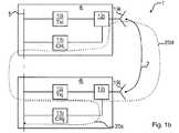
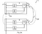
図1a〜図1bはメイン送信器とキャリブレーション受信器とを用いた実施例を示すブロック図であり、図2a〜図2bはメイン受信器とキャリブレーション送信器とを用いた実施例を示すブロック図である。この実施例はまた、アンテナ要素間の相互結合を利用している。図1a〜図1bと図2a〜図2bとを参照してアンテナアレイのキャリブレーションについて提案する方法を検討する。Illustration 1a~ Figure 1bwith reference to the accompanying drawings is a block diagram showing an embodiment using a main transmitter and calibration receiver, FIG 2a~-2b were used and the main receiver and calibration transmitter It is a block diagram which shows an Example. This embodiment also utilizes mutual coupling between the antenna elements. Consider a proposed method for antenna array calibration with reference to FIGS. 1a-1b and 2a-2b.
TXi10iはi番目の送信器無線モジュール4iの送信器を示し、RXi14iは少なくとも2つの無線モジュールを有するアンテナアレイ1のi番目の受信器無線モジュール3iの受信器を示している。同様に、TXj10jはj番目の送信器無線モジュール4jの送信器を示し、RXj14jはそのアンテナアレイのj番目の受信器無線モジュール3jの受信器を示している。なお、i番目とj番目の無線モジュールは同じアンテナアレイモジュールに、或いは、近接するアンテナアレイモジュールに配置される。
複数の送信器と受信器と同様に、CRi11iはi番目の送信器無線モジュールに接続されたキャリブレーション受信器を示し、CTi15iはi番目の受信器無線モジュールに接続されたキャリブレーション送信器を示している。同様に、CRj11jはj番目の送信器無線モジュールに接続されたキャリブレーション受信器を示し、CTj15jはj番目の受信器無線モジュールに接続されたキャリブレーション送信器を示している。なお、i番目とj番目のキャリブレーション受信器或いは送信器は同じ物理受信器或いは送信器を複数の無線モジュールと複数のアンテナとを同じキャリブレーション受信器或いは送信器に接続するキャリブレーションネットワークにより共用しても良い。ただし、この場合には、これらの無線モジュールとアンテナとが同じアンテナアレイモジュールに配置されることが必要である。例えば、CRi11iのような示されたキャリブレーション受信器、或いは、CTi15iのような示されたキャリブレーション送信器は、それ故に、i番目の送信或いは受信無線モジュールを接続し、こうして、特定のキャリブレーション経路を構成するキャリブレーションネットワークの関連部分を含むものとして解釈されるべきである。Like multiple transmitters and receivers,
各無線モジュールの主目的は、無線信号を送受信することにある。何らかの適切な数の無線モジュールがアンテナアレイ1の一部となる。なお、図1a〜図1bにはRX無線モジュールが示され、図2a〜図2bにはTX無線モジュールが示されているが、1つのRX無線モジュールと1つのTX無線モジュールとが無線モジュールのデュープレックスフィルタを用いることにより同じ物理アンテナを共用しても良い。またなお、アンテナは1つのアンテナ要素、或いは、アンテナの副アレイにおいて接続された複数のアンテナ要素を含むことができる。 The main purpose of each wireless module is to transmit and receive wireless signals. Any suitable number of wireless modules become part of the
図1a〜図1bには、2つの送信(TX)無線モジュール4i,4jが示されている。第1のTX無線モジュール4iはメイン送信器10iを含む、それに付随するアンテナ10iをもっている。キャリブレーション受信器(CR)11iが制御可能な多指向性のカップラ12iを介してメイン送信器10iとアンテナ19iに接続されている。第2のTX無線モジュール4jも同様な構成であり、付随するアンテナ19jとともにそれ自身のメイン送信器10jを有している。キャリブレーション受信器11jは制御可能な多指向性のカップラ12jを介してメイン送信器10jとアンテナ19jに接続されている。なお、i番目とj番目のキャリブレーション受信器は、キャリブレーションネットワークを介して、つまり特定のキャリブレーション経路を構成する異なる送信無線モジュールに接続された同じ物理受信器を共用できる。アンテナアレイ1の全てのTX無線モジュール4i,4jに共通の基準平面(RP)5が定義される。アンテナ要素19iと19jとの間には、方向に依存して、AijとAjiとしても示される相互接続2がある。ここで示すモデルでは、相互接続は相互交換可能である、即ち、Aij=Ajiであると仮定する。In FIG. 1a-b, two transmit (TX)
図2a〜図2bには、2つの受信(RX)無線モジュール3i,3jが示されている。第1のRX無線モジュール3iは付随するアンテナ19iを備えたメイン受信器14を含む。キャリブレーション送信器(CT)15iが制御可能な多指向性のカップラ12iを介してメイン受信器14iとアンテナ19iに接続されている。第2のRX無線モジュール3jも同様な構成であり、付随するアンテナ19jとともにそれ自身のメイン受信器14jを有している。キャリブレーション送信器15jは制御可能な多指向性のカップラ12jを介してメイン受信器14jに接続されている。なお、i番目とj番目のキャリブレーション送信器は、キャリブレーションネットワークを介して、つまり特定のキャリブレーション経路を構成する異なる受信無線モジュールに接続された同じ物理送信器を共用できる。全てのRX無線モジュール3i,3jに、そして、オプション的にはアンテナアレイ1の全てのRX無線モジュール3i,3jと全てのTX無線モジュール4i,4jの両方に共通の基準平面5が定義される。 In FIG. 2a-2b, two receive (RX) radio modules 3i, 3j are shown. The first RX radio module 3i includes a
多指向性のカップラ12i−jについて、カップリングファクタは、全ての実際的な目的のために、無線側及びアンテナ側について等しいと想定する。 For
アンテナアレイ1のキャリブレーションは、複数のアンテナポートにおける無線信号を合わせるために、1つ以上の無線モジュールにおいて位相と利得と遅延との内の少なくともいずれかに対する修正のために計算を行うことが関係している。TXとRXの両方について、その修正はデジタル領域で適用される。これについては図3を参照してより詳細に後で説明する。 Calibration of the
示されている無線モジュール4i−jと3i−jとの内の少なくともいずれかはアンテナアレイ1の一部、或いは、アンテナアレイ1の複数のモジュールの一部を形成する。また、図1a〜図1bに示されているのはTX無線モジュールのキャリブレーションのための手順の4つの測定経路20a〜20dであり、図2a〜図2bに示されているのはRX無線モジュールのキャリブレーションのための手順の4つの測定経路20e〜20hである。 At least one of the illustrated
アンテナ要素19iと19jとの間で、方向に依存して、AijとAjiとしても示される相互接続2がある。ここで示すモデルでは、相互接続は相互交換可能である、即ち、Aij=Ajiであると仮定する。Between
基準平面5は、キャリブレーション信号が注入されるか或いは受信される場所であり、それから、その完了後、特定の測定経路20a〜20hが比較され、元々の注入された信号に対する相関がとられて応答を取得する。この相関処理により、問題としている測定経路20a〜20hに関して、トータルの位相オフセットと振幅変化と遅延との内、少なくともいずれかが与えられる。 The reference plane 5 is where the calibration signal is injected or received, after which the
i番目の無線モジュールとj番目の無線モジュールとの間の基準平面5に沿った遅延は、例えば、複数のアンテナアレイモジュール間の信号伝播遅延を表わしており、これはRPijにより示される。アンテナキャリブレーションのために、基準平面5に沿って発生するどんな遅延も知られており、修正されるとは想定しない。The delay along the reference plane 5 between the i-th radio module and the j-th radio module represents, for example, a signal propagation delay between a plurality of antenna array modules, which is indicated by RPij . For antenna calibration, any delay that occurs along the reference plane 5 is known and is not assumed to be corrected.
しかしながら、もし受信モジュールにおいて受信した信号からのキャリブレーション信号のキャンセレーションについてのキャンセレーションパラメータ、或いは、アンテナ相互結合Aijが更なる目的のために計算されることになるなら、この遅延は知られなければならない。この技術分野では、もしその遅延が相互交換可能性のあるもの、即ち、RPij=RPjiであると仮定するなら、2つの地点間の伝播時間遅延をどのように得るのかについては知られている。例えば、問題としている2つの地点間のトータルメッセージ時間RPij+RPjiを往復して直接測定したり、或いは、共通地点からの経路D1とD2とに沿って送信される2つのメッセージについての到着時刻M1とM2を2つの地点で測定することにより、このことはなされる。これらのメッセージの内の1つはまた、これらの地点の間のリンクを通過する。このことは、M1=(D2+RPji)−D1とM2=(D1+RPij)−D2とを与え、シークタイム遅延はRP=(M1+M2)/2となるであろう。However, this delay is known if the cancellation parameters for the cancellation of the calibration signal from the signal received at the receiving module, or the antenna mutual coupling Aij is to be calculated for further purposes. There must be. In this technical field it is known how to obtain the propagation time delay between two points if the delay is assumed to be interchangeable, ie RPij = RPji. Yes. For example, the total message time RPij + RPji between the two points in question can be directly measured back and forth, or the arrival times for two messages transmitted along the routes D1 and D2 from the common point This is done by measuring M1 and M2 at two points. One of these messages also passes over the link between these points. This gives M1 = (D2 + RPji ) −D1 and M2 = (D1 + RPij ) −D2, and the seek time delay will be RP = (M1 + M2) / 2.
なお、オプション的には、送信無線モジュール4i,4jのキャリブレーションに関し、各キャリブレーション受信器により受信したキャリブレーション信号として、送信が意図された正規の無線信号を用いることも可能である。 As an option, regarding the calibration of the
キャリブレーションのための数値の計算
次に、異なる経路20a〜20hを用いて、相対的キャリブレーションのための数値がどのように計算されるのかを示す。この方法には、測定手順を実行し、無線モジュールとこれに関係するアンテナ要素との各ペアについて複数のキャリブレーション測定経路を設定することが関係している。そのような4つの可能な測定経路があり、その内の2つはアンテナ相互結合を含む。これら4つの測定から、必要な位相、利得、遅延修正が、無線モジュールに対して、また、キャリブレーションモジュールとアンテナ相互結合についての全ての特性に対しても計算される。完全な測定と計算手順とは、全ての無線モジュールが少なくとも1つの手順に含められ、無線モジュールの複数のペア間における相対的キャリブレーションの連続したチェインが確立されるまで繰り返される。Calculation of numerical values for calibration Next, it will be shown how the numerical values for relative calibrationare calculated using
NT個のTX無線モジュール4i,4jとNR個のRX無線モジュール3i,3jとを含むアクティブアンテナアレイを考える。ここで、各モジュールは対応するアンテナ要素19i,19jに接続される。なお、TX無線モジュールとRX無線モジュールの数は同じである必要はない。即ち、個数NはTXとRXとに対して異なっていても良い。Consider an active antenna array that includes NT
TXi、RXi、10i、14iは無線経路を示し、TXとRXに対してi=1,2,……Nであり、
CRi、CTi、11j、14iは、受信器或いは送信器のキャリブレーション経路を示し、
Aijはアンテナ経路に対するアンテナの相互結合を示し、i≠jであり、
RPijは基準平面5における経路を示し、i≠jであり、
pii、pijは測定経路20a−hの応答を示している。TXi , RXi , 10i, 14i denote radio paths, i = 1, 2,... N for TX and RX,
CRi , CTi , 11j, 14i indicate the calibration path of the receiver or transmitter,
Aij indicates the mutual coupling of the antenna to the antenna path, i ≠ j,
RPij represents a path in the reference plane 5, i ≠ j,
pii and pij indicate the responses of the
複素伝達関数は各経路に対して、
Hi=gi・exp{j(ωτi+φi)} [1]
として定義され、
giは利得の絶対値を示し、
τiは遅延を示し、
φiは位相オフセットを示し、
ωは角周波数を示す。The complex transfer function is
Hi = gi · exp {j (ωτi + φi )} [1]
Defined as
gi represents the absolute value of the gain,
τi indicates the delay,
φi indicates the phase offset,
ω represents an angular frequency.
計算式を簡単にするために、伝達関数の対数が次の方程式では用いられる。式[1]の対数表現版は、複数のブロックを測定経路へと組み合わせた結果を計算したり、或いは、複数の測定からの結果を組み合わせたりする場合、乗算を加算へと書き換える。利得の一般に用いられる対数値は、dB(gi)=20・log10(gi)によって定義されるdB値である。次に、図1a〜図1bと図2a〜図2bとからの記号表記TXi,RXiなどを用いて、異なる経路20a〜20hにおけるキャリブレーションエンティティであるdB(gi)、τi、或いは、φiを表わす。To simplify the formula, the logarithm of the transfer function is used in the following equation: The logarithmic representation version of Equation [1] rewrites multiplication to addition when computing the result of combining multiple blocks into a measurement path, or when combining results from multiple measurements. A commonly used logarithmic value of gain is the dB value defined by dB (gi ) = 20 · log10 (gi ). Next, using the symbolic notations TXi , RXi, etc. from FIGS. 1 a-1 b and 2 a-2 b, the calibration entities dB (gi ), τi , or in different paths 20 a-20 h , Φi .
次の方程式のいくつかで計算される平均値はまた、dB(gi)に対しても適用するし、この対数平均は、線形利得値を用いる場合には、幾何学的平均である
mean(gi,gj)=√(gi,gj)
へと書き戻される。式[1]の元々の線形表現形式を用いると(幾何学的平均の公式にあるように)加算は乗算に、減算は除算になり、2で割ることは平方根の抽出になる。The mean value calculated in some of the following equations also applies to dB (gi ), and this logarithmic mean is the geometric mean when using linear gain values.
mean (gi , gj ) = √ (gi , gj )
Will be written back. Using the original linear form of Equation [1] (as in the geometric mean formula), addition is a multiplication, subtraction is a division, and division by 2 is a square root extraction.
TXキャリブレーション
図1aと図1bにおいて、応答を含む測定経路マトリクスPの要素は、
経路20aに対応して、
pii=TXi+CRi [2]
経路20bに対応して、
pij=TXi+Aij+CRj+RPij、i≠j
経路20cに対応して、
pjj=TXj+CRj
経路20dに対応して、
pji=TXj+Aji+CRi+RPji、i≠j
である。TX Calibration In FIGS. 1a and 1b, the elements of the measurement path matrix P including the response are
Corresponding to the
pii = TXi + CRi [2]
Corresponding to the
pij = TXi + Aij + CRj + RPij , i ≠ j
Corresponding to the
pjj = TXj + CRj
Corresponding to the
pji = TXj + Aji + CRi + RPji , i ≠ j
It is.
TXアンテナ結合マトリクスATXは相互交換可能の特性、
Aij=Aji、i≠j [3]
をもつ。TX antenna coupling matrix ATX is an interchangeable property,
Aij = Aji , i ≠ j [3]
It has.
差分pij−piiとpji−pjjとをとると、Aij=Ajiなので、ATXの要素を次のように与えることができる。即ち、
Aij=1/2{pij+pji−(pii+pjj)−(RPij+RPji)} [4]
である。Taking the differences pij −pii and pji −pjj , since Aij = Aji , the elements of ATX can be given as follows. That is,
Aij = 1/2 {pij + pji − (pii + pjj ) − (RPij + RPji )} [4]
It is.
測定差分マトリクスは次に、式[2]の適切な副方程式の差分をとることで、
dCRii=CRi−CRi=0 [5]
dCRij=CRi−CRj=pii+Aij−pij+RPji、i≠j
dCRji=CRj−CRi=pjj+Aji−pji+RPij、i≠j
そして、
dTXii=TXi−TXi=0 [6]
dTXij=TXi−TXj=pii+Aji−pji+RPij、i≠j
dTXji=TXj−TXi=pjj+Aij−pij+RPji、i≠j
を与える。The measurement difference matrix then takes the difference of the appropriate sub-equation of equation [2],
dCRii = CRi −CRi = 0 [5]
dCRij = CRi −CRj = pii + Aij −pij + RPji , i ≠ j
dCRji = CRj -CRi = pjj + Aji -pji + RPij , i ≠ j
And
dTXii = TXi −TXi = 0 [6]
dTXij = TXi -TXj = pii + Aji -pji + RPij , i ≠ j
dTXji = TXj −TXi = pjj + Aij −pij + RPji , i ≠ j
give.
dCRiiと−dCRjiの平均、dTXijと−dTXjiの平均をとると、Aij=Aji、RPij=RPjiなので、
d−CRij=1/2{pii−pjj−(pij−pji)} [7]
そして、
d−TXij=1/2{pii−pjj+(pij−pji)} [8]
を与える。Taking the average of dCRii and -dCRji and the average of dTXij and -dTXji , Aij = Aji and RPij = RPji
d− CRij = 1/2 {pii −pjj − (pij −pji )} [7]
And
d− TXij =½ {pii −pjj + (pij −pji )} [8]
give.
式[8]から得られる結果は、アンテナポートiとjでの信号を合わせるためにj番目のTX無線モジュールに加算されるべき修正形式でのキャリブレーションパラメータである。なお、アンテナに対する経路Aと基準平面に対するRPは、相互交換性の条件のためにキャンセルされるであろう。用いられる定義によれば、この修正は、加算されるdB利得(或いは乗算される線形利得ファクタ)、遅延、或いは、実際の角周波数において適用されるオフセット位相角であろう。これらの修正は、それ自身で、或いは、組み合わされて、例えば、適切に調整されたFIRフィルタを用いてデジタルベースバンドにおいて適用される。 The result obtained from equation [8] is a calibration parameter in a modified form to be added to the jth TX radio module to match the signals at antenna ports i and j. Note that the path A to the antenna and the RP to the reference plane will be canceled due to interoperability conditions. According to the definition used, this modification would be the added dB gain (or multiplied linear gain factor), delay, or offset phase angle applied at the actual angular frequency. These modifications can be applied on their own or in combination, for example in the digital baseband using an appropriately tuned FIR filter.
完全なTX測定と計算手順は、全てのTX無線モジュールが少なくとも1つの手順に含められ、TX無線モジュールの複数のペア間における相対的キャリブレーションの連続したチェインが確立されるまで、他のTX無線モジュールを含めて、繰り返される。 The complete TX measurement and calculation procedure is followed by other TX radios until all TX radio modules are included in at least one procedure and a continuous chain of relative calibration between multiple pairs of TX radio modules is established. Repeated, including the module.
RXキャリブレーション
図2aと図2bにおいて、TXキャリブレーションに対するのと同様の検討をして、測定経路マトリクスPの要素は、
経路20eに対応して、
pii=CTi+RXi [9]
経路20fに対応して、
pij=CTi+Aij+RXj+RPji、i≠j
経路20gに対応して、
pjj=CTj+RXj
経路20hに対応して、
pji=CTj+Aji+RXi+RPij、i≠j
である。RX calibration In FIGS. 2a and 2b, the same considerations as for TX calibration are made and the elements of the measurement path matrix P are:
Corresponding to the
pii = CTi + RXi [9]
Corresponding to the
pij = CTi + Aij + RXj + RPji , i ≠ j
Corresponding to the
pjj = CTj + RXj
Corresponding to the
pji = CTj + Aji + RXi + RPij , i ≠ j
It is.
RXアンテナ結合マトリクスARXは相互交換可能の特性、
Aij=Aji、i≠j [10]
をもつ。RX antenna coupling matrix ARX has interchangeable characteristics,
Aij = Aji , i ≠ j [10]
It has.
差分pij−piiとpji−pjjとをとると、Aij=Ajiなので、ARXの要素を次のように与えることができる。Taking the differences pij −pii and pji −pjj , since Aij = Aji , the elements of ARX can be given as follows.
即ち、
Aij=1/2{pij+pji−(pii+pjj)−(RPij+RPji)} [11]
である。That is,
Aij = 1/2 {pij + pji − (pii + pjj ) − (RPij + RPji )} [11]
It is.
なお、これは式[4]と同じ表現となる。 This is the same expression as Equation [4].
測定差分マトリクスは次に、式[9]の適切な副方程式の差分をとることで、
dCTii=CTi−CTi=0 [12]
dCTij=CTi−CTj=pii+Aji−pji+RPij、i≠j
dCTji=CTj−CTi=pjj+Aij−pij+RPji、i≠j
そして、
dRXii=RXi−RXi=0 [13]
dRXij=RXi−RXj=pii+Aij−pij+RPji、i≠j
dRXji=RXj−RXi=pjj+Aji−pji+RPij、i≠j
を与える。The measurement difference matrix then takes the difference of the appropriate sub-equation of equation [9],
dCTii = CTi −CTi = 0 [12]
dCTij = CTi −CTj = pii + Aji −pji + RPij , i ≠ j
dCTji = CTj −CTi = pjj + Aij −pij + RPji , i ≠ j
And
dRXii = RXi -RXi = 0 [13]
dRXij = RXi -RXj = pii + Aij -pij + RPji , i ≠ j
dRXji = RXj -RXi = pjj + Aji -pji + RPij , i ≠ j
give.
dCTijと−dCTjiの平均、dRXijと−dRXjiの平均をとると、Aij=Aji、RPij=RPjiなので、
d−CTij=1/2{pii−pjj+(pij−pji)} [14]
そして、
d−RXij=1/2{pii−pjj−(pij−pji)} [15]
を与える。Average dCTij and-DCTji, taking the average of the DRXij and-dRX ji, A ij = A ji , because RPij = RPji,
d− CTij = 1/2 {pii −pjj + (pij −pji )} [14]
And
d− RXij = 1/2 {pii −pjj − (pij −pji )} [15]
give.
式[15]から得られる結果は、アンテナポートiとjでの信号を合わせるためにj番目のRX無線モジュールに加算されるべき修正形式でのキャリブレーションパラメータである。なお、アンテナに対する経路Aと基準平面に対するRPは、相互交換性の条件のためにキャンセルされるであろう。用いられる定義によれば、この修正は、加算されるdB利得(或いは乗算される線形利得ファクタ)、遅延、或いは、実際の角周波数において適用されるオフセット位相角であろう。これらの修正は、それ自身で、或いは、組み合わされて、例えば、適切に調整されたFIRフィルタを用いてデジタルベースバンドにおいて適用される。 The result obtained from equation [15] is a calibration parameter in a modified form to be added to the j th RX radio module to match the signals at antenna ports i and j. Note that the path A to the antenna and the RP to the reference plane will be canceled due to interoperability conditions. According to the definition used, this modification would be the added dB gain (or multiplied linear gain factor), delay, or offset phase angle applied at the actual angular frequency. These modifications can be applied on their own or in combination, for example in the digital baseband using an appropriately tuned FIR filter.
完全なRX測定と計算手順は、全てのRX無線モジュールが少なくとも1つの手順に含められ、RX無線モジュールの複数のペア間における相対的キャリブレーションの連続したチェインが確立されるまで、他のRX無線モジュールを含めて、繰り返される。 The complete RX measurement and calculation procedure is the same for other RX radios until all RX radio modules are included in at least one procedure and a continuous chain of relative calibration between multiple pairs of RX radio modules is established. Repeated, including the module.
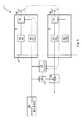
図3はキャリブレーションパラメータを適用する調整器を含むアンテナアレイを示すブロック図である。ここで、各無線モジュールは、ここで説明するキャリブレーションパラメータを適用する調整器を含んでいる。複数のTX無線モジュール4i−jのそれぞれは各調整器16i−jを含む。同様に、複数のRX無線モジュール3i−jのそれぞれは各調整器17i−jを含む。調整器16i−j、17i−jは、キャリブレーションパラメータが適用可能な何らかの適切な構成、例えば、FIRフィルタなどであると良い。 FIG. 3 is a block diagram illustrating an antenna array including an adjuster that applies calibration parameters. Here, each wireless module includes an adjuster that applies the calibration parameters described herein. Each of the plurality of
コントローラ22は上述したようにキャリブレーションパラメータ抽出の監視を担当し、また、1つ以上の調整器16i−j,17i−jを用いて取得したキャリブレーションパラメータを適用する。 The
図4は実施例に従う方法を示すフローチャートである。その方法は、図1a〜図1bと図2a〜図2bとを参照して上述した手順を説明する別の例である。その方法は、図3のコントローラ22のように、図1a〜図1bと図2a〜図2bのアンテナアレイ1に含まれるか、或いは、アンテナアレイ1に接続されるコントローラで実行される。 FIG. 4 is a flowchart illustrating a method according to an embodiment. The method is another example illustrating the procedure described above with reference to FIGS. 1a-1b and 2a-2b. The method is performed by a controller included in or connected to the
初期のキャリブレーション信号注入ステップ30では、キャリブレーション信号が無線モジュールに注入される。無線モジュールがRX無線モジュールである場合、その信号はキャリブレーション送信器CT15i−jと付随するキャリブレーションネットワークを介してアンテナに近い結合ポイントに注入される。無線モジュールがTX無線モジュールである場合、その信号は無線デジタル領域において注入される。また、その信号は送信が意図されている正規の無線信号でも良い。 In an initial calibration signal injection step 30, a calibration signal is injected into the wireless module. If the radio module is an RX radio module, its signal is injected into the coupling point close to the antenna via the calibration transmitter CT15i-j and the associated calibration network. If the radio module is a TX radio module, its signal is injected in the radio digital domain. The signal may be a regular radio signal intended for transmission.
測定応答ステップ32では、注入されたキャリブレーション信号に対する第1の応答がそのキャリブレーション信号が注入されたのと同じ第1のRX無線モジュールにおいて測定されるか、或いは、その同じ第1のRX無線モジュールに接続されたキャリブレーション受信器CR11iにおいて測定される。これにより、RXについては第1の経路20eでTXについては経路20aで測定がなされる。 In a measurement response step 32, a first response to the injected calibration signal is measured at the same first RX radio module as the calibration signal was injected, or the same first RX radio. It is measured in a calibration receiver CR11i connected to the module. As a result, measurement is performed on the
繰り返しステップ34では、その方法はステップ30に戻り、キャリブレーション信号注入ステップ30と応答測定ステップ32とを繰り返すが、このときには、例えば、制御可能な多指向性カップラを用いて異なる経路を選択する。 In a
注入と応答のループが3回繰り返され、順番にそれが注入されたのとは異なる第2のRX無線モジュールにおいて、或いは、それが注入されたのとは異なる第2のTX無線モジュールに接続されたキャリブレーション受信器CR11jにおいて、注入されたキャリブレーション信号に対する応答を測定すると、その結果、経路20fと20bとを測定することになる。 The injection and response loop is repeated three times and connected in sequence to a second RX radio module that is different from the one that was injected, or to a second TX radio module that is different from the one that was injected. When the response to the injected calibration signal is measured in the calibration receiver CR11j, the
最後の2つのループでは、キャリブレーション信号が第2の無線モジュールに注入され、そのキャリブレーション信号が注入されたのと同じ第2のRX無線モジュールにおいて、或いは、そのキャリブレーション信号が注入されたのと同じ第2のTX無線モジュールに接続されたキャリブレーション受信器CR11jにおいて、第3番目の応答が測定され、その結果、経路20gと20cとを測定することになる。それが注入されたのとは異なる第1のRX無線モジュールにおいて、或いは、そのキャリブレーション信号が注入されたのとは異なる第1のRX無線モジュールに接続されたキャリブレーション受信器CR11iにおいて、注入されたキャリブレーション信号に対する第4番目の応答が測定され、その結果、最後の経路20hと20dとを測定することになる。それから、この方法は数値計算ステップ36に進む。 In the last two loops, the calibration signal was injected into the second radio module, either in the same second RX radio module that the calibration signal was injected into, or the calibration signal was injected In the calibration receiver CR11j connected to the same second TX radio module, the third response is measured, and as a result, the
数値計算ステップ36では、現在のキャリブレーションがTX無線モジュールに関するものである場合、式[8]が計算される。そうでなければ、現在のキャリブレーションがRX無線モジュールに関するものである場合、式[15]が計算される。 In the
一旦、その数値が得られたなら、キャリブレーションパラメータがキャリブレーションパラメータ計算ステップ38で計算される。このステップの一部は前のステップで得られた数値を所望の値、例えば、2つの無線モジュールの間を差を最小にする場合にはゼロ“0”値と比較することでも良い。もし差がある場合、オプション的には閾値より大きい絶対的な差がある場合、例えば、FIRフィルタに対して適切なパラメータが計算される。 Once the numerical value is obtained, calibration parameters are calculated in calibration
キャリブレーション適用ステップ40では、何らかの新しいキャリブレーションパラメータが、例えば、無線モジュールの調整器のFIRフィルタに対する係数として適用される。 In the calibration application step 40, some new calibration parameters are applied, for example, as coefficients for the FIR filter of the wireless module adjuster.
条件付き繰り返しステップ42では、まだキャリブレーション計算の一部となっていない無線モジュールがあるかどうかを判断する。そのようなモジュールがある場合には、この方法はキャリブレーション信号注入ステップ30に戻り、処理に新しい、以前に計算されていないモジュールと、以前にキャリブレーション計算の一部となった無線モジュールとを含める。 In
オプション的には、このキャリブレーション方法はアイドル期間の後には再び実行される。そのアイドル期間は、何らかの適当な長さ、例えば、10秒、1分、10分などであるように選択される。 Optionally, this calibration method is performed again after an idle period. The idle period is selected to be any suitable length, eg, 10 seconds, 1 minute, 10 minutes, etc.
図5はキャンセレーション回路を含むアンテナアレイの実施例を示すブロック図である。これはRX無線モジュール3i−jも適用され、キャリブレーション送信器CTからの追加されたキャリブレーション信号が干渉体として作用し、これは潜在的には信号雑音比が低下するなどの不利益となる。この注入されたキャリブレーション信号のキャンセレーションがこの問題を解決する。なお、このキャンセレーションは不完全なものであり、従って、キャンセレーションの適用後にも、元々の或いは修正信号のわずかな部分は依然として残留する。 FIG. 5 is a block diagram showing an embodiment of an antenna array including a cancellation circuit. This also applies to the RX radio module 3i-j, and the added calibration signal from the calibration transmitter CT acts as an interferer, which is potentially detrimental such as a reduced signal to noise ratio. . This cancellation of the injected calibration signal solves this problem. It should be noted that this cancellation is incomplete and, therefore, only a small portion of the original or modified signal remains after the cancellation is applied.
図5は図2aの経路20fの例を図示している。キャリブレーション信号発生器24はCTi15iで注入されるキャリブレーション信号を発生する。その信号はアンテナ19iへと通過していき、空中での複数のアンテナの相互結合により、アンテナ19jに達し、受信器RXj14jにより受信される。その測定された信号はコントローラ22に入力される。また、コントローラはキャリブレーション信号生成器24からの注入信号へのアクセスをもっている。事実、これは前述した手順と方法の一部であり、経路20fについては式[9]を参照し、その経路が減算器25に関するものだけである限りとられるものであることに注意すると、調整器23に適用する正しい修正量は、
cij=CTi+Aij+RXj−RPji [16]
となるであろう。FIG. 5 illustrates an example of the
cij = CTi + Aij + RXj −RPji [16]
It will be.
式[9]に関し、これはまた、
cij=pij−2・RPji [17]
と表現できる。For equation [9], this also
cij = pij -2 · RPji [17]
Can be expressed as
減算器25において受信信号から調整され生成されたキャリブレーション信号を減算することにより、受信信号において注入したキャリブレーション信号の影響は大きく低減されるか、或いは、実質的には除去されることさえもある。なお、このキャンセレーションは、式[9]の適切な部分を参照することにより、複数の経路20e〜20hのいずれかに対して注入したキャリブレーション信号をキャンセルするために用いられる。なおまた、基準平面に沿った遅延RPはこの場合には知られていなければならない。この遅延を得る方法はこの技術分野では公知であり、この説明で先に示した通りである。 By subtracting the calibration signal adjusted and generated from the received signal in the
このようにして、CTを用いて注入されたキャリブレーション信号は実質的にRX無線モジュールに対する受信信号から除去される。これによりキャリブレーションがオンラインでRXに対して正規の無線トラフィックに何ら大きな影響を与えることなく実行可能になる。TXに関しても、送信が意図された正規の入力信号のレベルが知られており、それ故に、注入されるキャリブレーション信号が送信される信号に干渉しないように、その注入されるキャリブレーション信号のレベルとスペクトラム分布とが選択されるので、この場合にも同じことが言える。また、オプションとして、送信が意図された正規の入力信号はTXモジュールに対するキャリブレーション信号として用いられる。 In this way, the calibration signal injected using CT is substantially removed from the received signal for the RX radio module. This allows calibration to be performed online without any significant impact on legitimate radio traffic for RX. Also for TX, the level of the regular input signal intended to be transmitted is known, and therefore the level of the injected calibration signal so that the injected calibration signal does not interfere with the transmitted signal. The same can be said in this case. Optionally, a regular input signal intended for transmission is used as a calibration signal for the TX module.
図6は実施例に従うカップラのブロック図である。そのカップラはカップラ52とスイッチ54とを有している。スイッチ54はコントローラ22により制御可能であり、キャリブレーションネットワークを介してスイッチ54の下で接続されるキャリブレーション送信器或いは受信器を、カップラ12の右側に接続されたアンテナ19、或いは、カップラ12の左側に接続されたメイン送信器10/受信器14に接続するよう設定される。 FIG. 6 is a block diagram of a coupler according to the embodiment. The coupler has a
結論
これまで示したように、式[8]と式[15]から得られたペアとなるような差d−TXijとd−RXijとは、アンテナアレイ、或いは、複数のアンテナアレイモジュールの構成におけるアンテナポートでの位相と、遅延と、そしておそらくは利得(対数利得或いはdB値を与える方程式)を合わせるためにTX無線モジュールのペア或いはRX無線モジュールのペアに適用されるべき相対的な修正を求めることになる。Conclusion As shown so far, the difference d− TXij and d− RXij that form a pair obtained from the equations [8] and [15] is the difference between the antenna array or a plurality of antenna array modules. Relative corrections to be applied to TX radio module pairs or RX radio module pairs to match the phase at the antenna port in the configuration, delay, and possibly gain (equation giving logarithmic gain or dB value) Will be asked.
アンテナポートは、アンテナ要素或いはアンテナの副アレイに対する電気的接続点として解釈されるべきである。しかしながら、そのアライメントは事実、多指向性カップリングポイントにおいて実行され、それ故に、アンテナポートにおけるアライメントはカップリングポイントと各アンテナポートとの間の複数の経路が均一(或いは、知られて修正される)ものであることを想定している。均一性の基準はしばしば、アンテナ近くにカップリングポイントを設置することによる設計により簡単に達成され、これにより電気的経路とその変動を最小にしている。それ故に、ここで提案された方法は、全ての実際的な目的のために、アンテナポートにおける求められる位置合わせを与えている。 An antenna port should be interpreted as an electrical connection point to an antenna element or subarray of antennas. However, the alignment is in fact performed at the multidirectional coupling point, and therefore the alignment at the antenna port is uniform (or known and corrected) for multiple paths between the coupling point and each antenna port. ) Is assumed. The uniformity criterion is often easily achieved by design by placing a coupling point close to the antenna, thereby minimizing the electrical path and its variation. Hence, the proposed method provides the required alignment at the antenna port for all practical purposes.
N個の無線モジュールと付随するアンテナとを備えたアンテナアレイに関し、式[8]と式[15]とに従って計算することが可能な(N−1)N/2個の平均差分値がある。これは、遠くに離して設置された付随するアンテナを備えた2つの無線モジュール間の差分値を、提案した方法のステップを用いて、隣接するアンテナ要素を接続するいくつかの異なる測定チェインにより、計算することがしばしば可能であることを意味している。さらにその上、要求される最小数(N−1)よりも多い差分値を用いて最小平均二乗の意味において差分値を解くことが可能であり、これにより、キャリブレーション精度を増している。 For an antenna array with N radio modules and associated antennas, there are (N−1) N / 2 average difference values that can be calculated according to equations [8] and [15]. This is because the difference value between two radio modules with associated antennas placed far apart is converted into several different measurement chains connecting adjacent antenna elements using the steps of the proposed method. It means that it is often possible to calculate. Furthermore, it is possible to solve the difference value in the sense of least mean squares using more difference values than the required minimum number (N-1), thereby increasing the calibration accuracy.
カップラポイントに接続するキャリブレーションネットワークをも含むキャリブレーション受信器とキャリブレーション送信器の経路とに関する式[7]と式[14]とから得られる結果は、アンテナキャリブレーションに対しては明示的に必要ではない。また、これらの経路における差分は修正される必要はない。しかしながら、これらのキャリブレーション経路は暗示的には提案された方法に含められており、これらの経路における何らかの変動や差分はそれ故に考慮されるものであり、無線モジュールのキャリブレーションが実行される程度の頻度では暗示的に修正されるものであることに留意されたい。提案された方法はそれ故に、キャリブレーションHW(ハードウェア)を特徴づけ、無線送信器と受信器ハードウェアのキャリブレーションにおけるのと同じ精度を達成するという課題を解決している。これはまた、経年変化とキャリブレーション経路とともに正規の無線送信器と受信器の経路に影響を及ぼす温度変化の問題をも解決する。 The results obtained from equations [7] and [14] for the calibration receiver, including the calibration network connected to the coupler point, and the path of the calibration transmitter are explicit for antenna calibration. Not necessary. Also, the differences in these paths need not be corrected. However, these calibration paths are implicitly included in the proposed method, and any variations or differences in these paths are therefore taken into account and the extent to which radio module calibration is performed. Note that this frequency is implicitly corrected. The proposed method therefore characterizes the calibration HW (hardware) and solves the problem of achieving the same accuracy as in calibration of radio transmitter and receiver hardware. This also solves the problem of temperature changes that affect the legitimate wireless transmitter and receiver paths as well as aging and calibration paths.
提案された方法ではアンテナの相互結合を使用するために、必要なキャリブレーションハードウェア(例えば、キャリブレーションカップラネットワーク、キャリブレーション受信器/送信器、信号相関器、キャリブレーション信号生成器)が1つのアンテナモジュールに対して局所的になる一方、キャリブレーションを拡張し、複数のアンテナアレイモジュールを含めることができる。 The proposed method requires one calibration hardware (eg calibration coupler network, calibration receiver / transmitter, signal correlator, calibration signal generator) to use antenna mutual coupling. While becoming local to the antenna module, the calibration can be extended to include multiple antenna array modules.
式[4]と式[11]とから得られる結果は、明示的に必要とされるアンテナ結合マトリクスに対してのものではないが、アンテナビームパターンがより良い精度へと修正される必要がある場合には、要求されるアプリケーションにおいて使用されても良い。このような場合があれば、基準平面に沿って発生する何らかの遅延は知られなければならない。この技術分野では、この説明において前に示したように、この伝播時間遅延をどのように取得するのかは公知である。 The results obtained from equations [4] and [11] are not for the explicitly required antenna coupling matrix, but the antenna beam pattern needs to be modified to better accuracy. In some cases, it may be used in a required application. If this is the case, any delay that occurs along the reference plane must be known. It is well known in the art how to obtain this propagation time delay, as indicated earlier in this description.
図7はコンピュータ可読手段を含むコンピュータプログラム製品70の一例を示している。このコンピュータ可読手段に、コンピュータプログラム71が格納される。そのコンピュータプログラムによりコントローラがここで説明した実施例に従う方法を実行することができる。この例では、コンピュータプログラム製品は、CD(コンパクトディスク)やDVD(デジタル多目的ディスク)やブルーディスクのような光学ディスクである。上述のように、コンピュータプログラム製品はまた、コントローラ22に接続されたメモリとしても実施できる。コンピュータプログラム71がここでは模式的に描かれた光学ディスク上のトラックとして示されているが、コンピュータプログラムはコンピュータプログラム製品に対して適切である如何なる方法で格納されて良い。 FIG. 7 shows an example of a
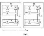
図8はアンテナアレイモジュールを例示するブロック図である。ここでは、アンテナアレイ1がどのように2つのアンテナアレイモジュール80a−bに分割されるのかが示されている。各アンテナアレイモジュール80a−bは複数の無線モジュール4i−jを含んでおり、各無線モジュールはメイン送信器10i−jを有している。各キャリブレーションネットワーク82a−bの使用により、キャリブレーション受信器11の選択的接続が可能になる。アンテナアレイモジュールは基準平面5を介して接続される。同様に、アンテナアレイはメイン受信器を含む無線モジュール3i−j、或いは、メイン受信器とメイン送信器の両方を含む無線モジュールとともに構成されても良い。 FIG. 8 is a block diagram illustrating an antenna array module. Here, it is shown how the
本発明を主として2〜3の実施例を参照して上記のように説明した。しかしながら、当業者であればすぐに認識することであるが、上記の開示した実施例以外の他の実施例も同様に、添付した請求の範囲で規定されるような発明の範囲内にある。 The invention has been described above mainly with reference to a few embodiments. However, one of ordinary skill in the art will readily recognize that other embodiments than the above disclosed embodiments are also within the scope of the invention as defined in the appended claims.
Claims (20)
Translated fromJapanese前記アンテナアレイ(1)は、
第1と第2の無線モジュール(3i−j,4i−j)と、
前記第1と第2の無線モジュールにそれぞれ接続された第1のアンテナ(19i)と第2のアンテナ(19j)とを有し、
前記第1と第2の無線モジュール(3i−j,4i−j)はそれぞれ、メイン送信器(10i−j)と選択的に接続可能なキャリブレーション受信器(11i−j)とを有するか、又は、
前記第1と第2の無線モジュール(3i−j,4i−j)はそれぞれ、メイン受信器(14i−j)と選択的に接続可能なキャリブレーション送信器(15i−j)とを有するものであって、前記方法は、
前記第1の無線モジュールにおいて第1のキャリブレーション信号を注入し(30)、前記第1の無線モジュールにおいて前記第1のキャリブレーション信号に対する第1の応答を測定する(32)工程と、
前記第1の無線モジュールにおいて第2のキャリブレーション信号を注入し、該第2のキャリブレーション信号が、前記第1と第2のアンテナの相互結合(2)を通過して前記第2の無線モジュールに達するようにし、前記第2の無線モジュールにおいて前記第2のキャリブレーション信号に対する第2の応答を測定する工程と、
前記第2の無線モジュールにおいて第3のキャリブレーション信号を注入し(30)、前記第2の無線モジュールにおいて前記第3のキャリブレーション信号に対する第3の応答を測定する工程と、
前記第2の無線モジュールにおいて第4のキャリブレーション信号を注入し、該第4のキャリブレーション信号が、前記第1と第2のアンテナの相互結合(2)を通過して前記第1の無線モジュールに達するようにし、前記第1の無線モジュールにおいて前記第4のキャリブレーション信号に対する第4の応答を測定する工程と、
前記第1の応答と前記第2の応答と前記第3の応答と前記第4の応答とを用いて少なくとも1つの数値を計算する(36)工程と、
前記計算された数値に基づいて少なくとも1つのキャリブレーションパラメータを計算する(38)工程とを有することを特徴とする方法。A method for obtaining at least one calibration parameter for an antenna array (1), comprising:
The antenna array (1)
First and second wireless modules (3i-j, 4i-j);
A first antenna (19i) and a second antenna (19j) connected to the first and second wireless modules, respectively;
Each of the first and second wireless modules (3i-j, 4i-j) has a main receiver (10i-j) and a calibration receiver (11i-j) that can be selectively connected; Or
Each of the first and second wireless modules (3i-j, 4i-j) has a main receiver (14i-j) and a calibration transmitter (15i-j) that can be selectively connected. And the method comprises
Injecting a first calibration signal in the first wireless module (30) and measuring a first response to the first calibration signal in the first wireless module (32);
A second calibration signal is injected in the first wireless module, and the second calibration signal passes through the mutual coupling (2) between the first and second antennas, and the second wireless module. And measuring a second response to the second calibration signal in the second wireless module; and
Injecting a third calibration signal in the second wireless module (30) and measuring a third response to the third calibration signal in the second wireless module;
A fourth calibration signal is injected in the second wireless module, and the fourth calibration signal passes through the mutual coupling (2) between the first and second antennas, and the first wireless module. And measuring a fourth response to the fourth calibration signal in the first wireless module; and
Calculating (36) at least one numerical value using the first response, the second response, the third response, and the fourth response;
Method characterized byhaving said calculating at least one calibration parameter based on the calculated number (38) step.
前記少なくとも1つのキャリブレーションパラメータは、該測定された量が所望の値に近づくように前記測定された量を調整することに向けられていることを特徴とする請求項1又は2に記載の方法。Measuring each of the first response, the second response, the third response, and the fourth response includes measuring a phase, delay, or logarithmic gain;
3. A method according to claim 1 or 2, wherein the at least one calibration parameter is directed to adjusting the measured quantity such that the measured quantity approaches a desired value. .
前記数値を用いて少なくとも1つのキャンセレーションパラメータを計算する工程と、
前記少なくとも1つのキャンセレーションパラメータを適用する工程と、
前記メイン受信器(14i−j)により受信した前記応答から前記注入されたキャリブレーション信号を減算する工程とをさらに有することを特徴とする請求項1乃至3のいずれか1項に記載の方法。When each of the first and second wireless modules (3i-j) has a main receiver (14i-j),
Calculating at least one cancellation parameter using the numerical value;
Applying the at least one cancellation parameter;
4. The method according to claim 1, further comprising the step of subtracting the injected calibration signal from the response received by the main receiver (14i-j).
前記繰り返しの実行において、前記第1の無線モジュールと前記第2の無線モジュールとの内の少なくとも1つは、前記方法の以前の実行において用いられた無線モジュールであることを特徴とする請求項1乃至7のいずれか1項に記載の方法。If there is a wireless module with at least one calibration parameter remaining to be calculated, the method is repeated (42),
2. In the repeated execution, at least one of the first wireless module and the second wireless module is a wireless module used in a previous execution of the method. The method of any one of thru | or7 .
前記第1と第2の無線モジュール(3i−j,4i−j)はそれぞれ、メイン送信器(10i−j)と選択的に接続可能なキャリブレーション受信器(11i−j)とを有するか、又は、
前記第1と第2の無線モジュール(3i−j,4i−j)はそれぞれ、メイン受信器(14i−j)と選択的に接続可能なキャリブレーション送信器(15i−j)とを有するものであって、
前記アンテナアレイは、
前記第1の無線モジュールにおいて第1のキャリブレーション信号を注入し(30)、前記第1の無線モジュールにおいて前記第1のキャリブレーション信号に対する第1の応答を測定し、
前記第1の無線モジュールにおいて第2のキャリブレーション信号を注入し、該第2のキャリブレーション信号が、前記第1と第2のアンテナの相互結合(2)を通過して前記第2の無線モジュールに達するようにし、前記第2の無線モジュールにおいて前記第2のキャリブレーション信号に対する第2の応答を測定し、
前記第2の無線モジュールにおいて第3のキャリブレーション信号を注入し(30)、前記第2の無線モジュールにおいて前記第3のキャリブレーション信号に対する第3の応答を測定し、
前記第2の無線モジュールにおいて第4のキャリブレーション信号を注入し、該第4のキャリブレーション信号が、前記第1と第2のアンテナの相互結合(2)を通過して前記第1の無線モジュールに達するようにし、前記第1の無線モジュールにおいて前記第4のキャリブレーション信号に対する第4の応答を測定するように構成され、
前記コントローラは、
前記第1の応答と前記第2の応答と前記第3の応答と前記第4の応答とを用いて少なくとも1つの数値を計算し(36)、前記計算された数値に基づいて少なくとも1つのキャリブレーションパラメータを計算する(38)ように構成されていることを特徴とするアンテナアレイ。A controller (22), first and second radio modules (3i-j, 4i-j), a first antenna (19i) connected to the first and second radio modules, and a second An antenna array (1) having an antenna (19j),
Each of the first and second wireless modules (3i-j, 4i-j) has a main receiver (10i-j) and a calibration receiver (11i-j) that can be selectively connected; Or
Each of the first and second wireless modules (3i-j, 4i-j) has a main receiver (14i-j) and a calibration transmitter (15i-j) that can be selectively connected. There,
The antenna array is
Injecting a first calibration signal in the first wireless module (30), measuring a first response to the first calibration signal in the first wireless module;
A second calibration signal is injected in the first wireless module, and the second calibration signal passes through the mutual coupling (2) between the first and second antennas, and the second wireless module. And measuring a second response to the second calibration signal at the second wireless module;
Injecting a third calibration signal in the second wireless module (30), measuring a third response to the third calibration signal in the second wireless module;
A fourth calibration signal is injected in the second wireless module, and the fourth calibration signal passes through the mutual coupling (2) between the first and second antennas, and the first wireless module. And is configured to measure a fourth response to the fourth calibration signal at the first wireless module;
The controller is
At least one numerical value is calculated using the first response, the second response, the third response, and the fourth response (36), and at least one calibration is performed based on the calculated numerical value. antenna array, characterized inthat it is configured to calculate Deployment parameters (38).
前記キャリブレーション受信器(11i−j)、又は、キャリブレーション送信器(15i−j)は、前記制御可能な多指向性のカップラ(12,12i−j)を介して各無線モジュール(3i−j,4i−j)内で接続されることを特徴とする請求項12乃至16のいずれか1項に記載のアンテナアレイ。Each wireless module further has a controllable multi-directional coupler (12,12i-j),
The calibration receiver (11i-j) or the calibration transmitter (15i-j) is connected to each wireless module (3i-j) via the controllable multi-directional coupler (12, 12i-j). , 4i-j), the antenna array according toany one of claims12 to 16 .
前記コントローラは、
前記第1の応答、前記第2の応答、前記第3の応答、又は、前記第4の応答から計算された少なくとも1つの数値に基づいて少なくとも1つのキャンセレーションパラメータを計算し、メイン受信器(14i−j)により受信した前記応答から前記キャリブレーション信号を減算するように構成されていることを特徴とする請求項12乃至17のいずれか1項に記載のアンテナアレイ。When each of the first and second wireless modules (3i-j) has a main receiver (14i-j),
The controller is
Calculating at least one cancellation parameter based on at least one numerical value calculated from the first response, the second response, the third response, or the fourth response; The antenna array according toany one of claims12 to 17, wherein the antenna array is configured to subtract the calibration signal from the response received according to 14i-j).
前記メイン受信器(14i−j)により受信した前記応答から前記調整された信号を減算するように構成された減算器(25)とをさらに有することを特徴とする請求項18に記載のアンテナアレイ。An adjuster (23) configured to apply the at least one cancellation parameter and obtain an adjusted signal;
19. The antenna array of claim18 , further comprising a subtractor (25) configured to subtract the adjusted signal from the response received by the main receiver (14i-j). .
Applications Claiming Priority (1)
| Application Number | Priority Date | Filing Date | Title |
|---|---|---|---|
| PCT/SE2010/051324WO2012074446A1 (en) | 2010-12-01 | 2010-12-01 | Method, antenna array, computer program and computer program product for obtaining at least one calibration parameter |
Publications (2)
| Publication Number | Publication Date |
|---|---|
| JP2014505392A JP2014505392A (en) | 2014-02-27 |
| JP5666717B2true JP5666717B2 (en) | 2015-02-12 |
Family
ID=44269263
Family Applications (1)
| Application Number | Title | Priority Date | Filing Date |
|---|---|---|---|
| JP2013541952AExpired - Fee RelatedJP5666717B2 (en) | 2010-12-01 | 2010-12-01 | Method for obtaining at least one calibration parameter and antenna array |
Country Status (5)
| Country | Link |
|---|---|
| EP (1) | EP2647084B1 (en) |
| JP (1) | JP5666717B2 (en) |
| CN (1) | CN103229354A (en) |
| AU (1) | AU2010364993B2 (en) |
| WO (1) | WO2012074446A1 (en) |
Families Citing this family (18)
| Publication number | Priority date | Publication date | Assignee | Title |
|---|---|---|---|---|
| US9680232B2 (en) | 2012-05-07 | 2017-06-13 | Qualcomm Incorporated | Graded-ground design in a millimeter-wave radio module |
| CN105393403B (en)* | 2013-07-08 | 2018-06-26 | 高通股份有限公司 | Techniques for Operating Phased Array Antennas in mmWave Radio Modules |
| WO2015085510A1 (en)* | 2013-12-11 | 2015-06-18 | Telefonaktiebolaget L M Ericsson (Publ) | Methods and apparatus for antenna calibration |
| WO2015143609A1 (en) | 2014-03-24 | 2015-10-01 | 华为技术有限公司 | Channel correction apparatus and method |
| US10009124B2 (en) | 2015-03-11 | 2018-06-26 | Telefonaktiebolaget Lm Ericsson (Publ) | Methods and apparatus for antenna calibration |
| US20170181166A1 (en)* | 2015-12-18 | 2017-06-22 | Qualcomm Incorporated | Run Time Radio Frequency Calibration for Receive Chains in Mobile Devices |
| WO2017145257A1 (en)* | 2016-02-23 | 2017-08-31 | 三菱電機株式会社 | Array antenna device and calibration method therefor |
| WO2017202453A1 (en) | 2016-05-24 | 2017-11-30 | Telefonaktiebolaget Lm Ericsson (Publ) | A method of determining sign of a calibration compensation |
| EP3465950B1 (en) | 2016-05-26 | 2020-07-15 | Telefonaktiebolaget LM Ericsson (Publ) | Method of calibrating an antenna system |
| US10944490B2 (en) | 2016-12-23 | 2021-03-09 | Telefonsktiebolsget LM Ericsson (Publ) | Antenna calibration for multiple input multiple output |
| PL3596780T3 (en) | 2017-03-13 | 2022-01-31 | Telefonaktiebolaget Lm Ericsson (Publ) | Self-calibration of antenna array system |
| EP3682508B1 (en) | 2017-09-15 | 2021-11-03 | Telefonaktiebolaget LM Ericsson (publ) | Systems and methods for self-calibration of an analog beamforming transceiver |
| CN108400785A (en)* | 2018-02-10 | 2018-08-14 | 广东圣大电子有限公司 | A kind of miniaturization microwave broadband victory frequency Up/Down Conversion system and calibration method |
| US11451311B2 (en) | 2018-11-05 | 2022-09-20 | Telefonaktiebolaget Lm Ericsson (Publ) | Method for antenna calibration and active antenna system for use in antenna calibration |
| CN110940957B (en)* | 2019-10-28 | 2022-03-22 | 惠州市德赛西威汽车电子股份有限公司 | Modular millimeter wave radar |
| US11558127B2 (en)* | 2020-10-19 | 2023-01-17 | Mediatek Inc. | Method for calibrating transmiter-to-receiver relative phase in millimeter wave beamforming system and associated millimeter wave antenna module |
| CN112635995B (en)* | 2020-12-30 | 2023-03-21 | 上海安费诺永亿通讯电子有限公司 | Antenna mutual coupling calibration configuration system and method |
| WO2025091211A1 (en)* | 2023-10-31 | 2025-05-08 | Telefonaktiebolaget Lm Ericsson (Publ) | Method and apparatus for calibration of an antenna array |
Family Cites Families (11)
| Publication number | Priority date | Publication date | Assignee | Title |
|---|---|---|---|---|
| US6157343A (en) | 1996-09-09 | 2000-12-05 | Telefonaktiebolaget Lm Ericsson | Antenna array calibration |
| US5657023A (en) | 1996-05-02 | 1997-08-12 | Hughes Electronics | Self-phase up of array antennas with non-uniform element mutual coupling and arbitrary lattice orientation |
| US5864317A (en)* | 1997-05-23 | 1999-01-26 | Raytheon Company | Simplified quadrant-partitioned array architecture and measure sequence to support mutual-coupling based calibration |
| ID27970A (en)* | 1998-08-05 | 2001-05-03 | Sanyo Electric Co | RADAS RADIO AND CALIBRATION METHODS FOR THAT |
| JP3651430B2 (en)* | 2001-09-17 | 2005-05-25 | 日本電気株式会社 | Array antenna calibration apparatus and calibration method |
| JP4478606B2 (en)* | 2005-05-19 | 2010-06-09 | 富士通株式会社 | Calibration apparatus and calibration method for linear array antenna |
| WO2008000318A1 (en)* | 2006-06-27 | 2008-01-03 | National University Of Ireland Maynooth | Antenna array calibration |
| JP5051385B2 (en)* | 2008-05-16 | 2012-10-17 | 日本電気株式会社 | Wireless communication apparatus using array antenna, calibration method thereof, and wireless communication base station system |
| JP2010034937A (en)* | 2008-07-30 | 2010-02-12 | Sony Corp | Wireless communication device, wireless communication method, and computer program |
| CN101651480B (en)* | 2008-08-14 | 2013-04-24 | 华为技术有限公司 | Active antenna, base station, method for updating amplitude and phase, and signal processing method |
| CN101626355B (en)* | 2009-08-11 | 2012-11-14 | 北京天碁科技有限公司 | Calibration device and calibration method of multi-input multi-output (MIMO) terminal |
- 2010
- 2010-12-01CNCN2010800704654Apatent/CN103229354A/enactivePending
- 2010-12-01WOPCT/SE2010/051324patent/WO2012074446A1/enactiveApplication Filing
- 2010-12-01JPJP2013541952Apatent/JP5666717B2/ennot_activeExpired - Fee Related
- 2010-12-01EPEP10795087.5Apatent/EP2647084B1/ennot_activeNot-in-force
- 2010-12-01AUAU2010364993Apatent/AU2010364993B2/ennot_activeCeased
Also Published As
| Publication number | Publication date |
|---|---|
| AU2010364993A1 (en) | 2013-05-02 |
| JP2014505392A (en) | 2014-02-27 |
| EP2647084A1 (en) | 2013-10-09 |
| EP2647084B1 (en) | 2015-02-18 |
| WO2012074446A1 (en) | 2012-06-07 |
| CN103229354A (en) | 2013-07-31 |
| AU2010364993B2 (en) | 2015-06-11 |
Similar Documents
| Publication | Publication Date | Title |
|---|---|---|
| JP5666717B2 (en) | Method for obtaining at least one calibration parameter and antenna array | |
| US8416126B2 (en) | Obtaining a calibration parameter for an antenna array | |
| US11942694B2 (en) | Self-calibration of antenna array system | |
| KR102048509B1 (en) | Apparatus and method for antenna array self-calibration | |
| US11668740B2 (en) | Over the air calibration and testing of beamforming-based multi-antenna devices in anechoic and non-anechoic environments | |
| Vieira et al. | Reciprocity calibration methods for massive MIMO based on antenna coupling | |
| CN102426300B (en) | Calibration system of amplitude and phase errors of satellite-borne wave beam formation reception channels and method thereof | |
| US20140204808A1 (en) | Tuning algorithm for multi-tap signal cancellation circuit | |
| CN108988963B (en) | A test method, launch equipment, test equipment and test system | |
| US20180198537A1 (en) | Technique For Calibrating An Antenna Array | |
| JP6821930B2 (en) | Calibration method for base stations, wireless communication systems and wireless communication systems | |
| US11996898B2 (en) | Method for determining a pre-equalization matrix and test setup | |
| US20170041975A1 (en) | Operation of a multi-standard base station site supporting at least two different radio access technologies | |
| WO2017081522A1 (en) | Simultaneous vswr measurement and coupler calibration at multiple antenna ports | |
| US20180323839A1 (en) | Channel condition estimation | |
| US9705662B2 (en) | System and method for radio full duplex | |
| EP3523893B1 (en) | Method and radio network node for determining total radiated power from a plurality of antennas | |
| US20220006537A1 (en) | Mobile-assisted phase calibration method and system | |
| Zhang et al. | Phases calibration of RIS using backpropagation algorithm | |
| US20250055575A1 (en) | Virtual cable calibration in over the air conformance testing | |
| CN107078780B (en) | Method for determining calibration weight coefficient and base station | |
| WO2023155080A1 (en) | Methods and apparatus for precoding matrix indicator generation | |
| HK40026036B (en) | Over the air calibration and testing of beamforming-based multi-antenna devices | |
| HK40026036A (en) | Over the air calibration and testing of beamforming-based multi-antenna devices |
Legal Events
| Date | Code | Title | Description |
|---|---|---|---|
| A977 | Report on retrieval | Free format text:JAPANESE INTERMEDIATE CODE: A971007 Effective date:20141128 | |
| TRDD | Decision of grant or rejection written | ||
| A01 | Written decision to grant a patent or to grant a registration (utility model) | Free format text:JAPANESE INTERMEDIATE CODE: A01 Effective date:20141208 | |
| A61 | First payment of annual fees (during grant procedure) | Free format text:JAPANESE INTERMEDIATE CODE: A61 Effective date:20141210 | |
| R150 | Certificate of patent or registration of utility model | Ref document number:5666717 Country of ref document:JP Free format text:JAPANESE INTERMEDIATE CODE: R150 | |
| LAPS | Cancellation because of no payment of annual fees |