JP5663280B2 - Control apparatus and control method - Google Patents
Control apparatus and control methodDownload PDFInfo
- Publication number
- JP5663280B2 JP5663280B2JP2010264389AJP2010264389AJP5663280B2JP 5663280 B2JP5663280 B2JP 5663280B2JP 2010264389 AJP2010264389 AJP 2010264389AJP 2010264389 AJP2010264389 AJP 2010264389AJP 5663280 B2JP5663280 B2JP 5663280B2
- Authority
- JP
- Japan
- Prior art keywords
- power
- consumer
- power system
- smart meter
- control
- Prior art date
- Legal status (The legal status is an assumption and is not a legal conclusion. Google has not performed a legal analysis and makes no representation as to the accuracy of the status listed.)
- Expired - Fee Related
Links
Images


Classifications
- Y—GENERAL TAGGING OF NEW TECHNOLOGICAL DEVELOPMENTS; GENERAL TAGGING OF CROSS-SECTIONAL TECHNOLOGIES SPANNING OVER SEVERAL SECTIONS OF THE IPC; TECHNICAL SUBJECTS COVERED BY FORMER USPC CROSS-REFERENCE ART COLLECTIONS [XRACs] AND DIGESTS
- Y02—TECHNOLOGIES OR APPLICATIONS FOR MITIGATION OR ADAPTATION AGAINST CLIMATE CHANGE
- Y02B—CLIMATE CHANGE MITIGATION TECHNOLOGIES RELATED TO BUILDINGS, e.g. HOUSING, HOUSE APPLIANCES OR RELATED END-USER APPLICATIONS
- Y02B70/00—Technologies for an efficient end-user side electric power management and consumption
- Y02B70/30—Systems integrating technologies related to power network operation and communication or information technologies for improving the carbon footprint of the management of residential or tertiary loads, i.e. smart grids as climate change mitigation technology in the buildings sector, including also the last stages of power distribution and the control, monitoring or operating management systems at local level
- Y02B70/3225—Demand response systems, e.g. load shedding, peak shaving
- Y—GENERAL TAGGING OF NEW TECHNOLOGICAL DEVELOPMENTS; GENERAL TAGGING OF CROSS-SECTIONAL TECHNOLOGIES SPANNING OVER SEVERAL SECTIONS OF THE IPC; TECHNICAL SUBJECTS COVERED BY FORMER USPC CROSS-REFERENCE ART COLLECTIONS [XRACs] AND DIGESTS
- Y02—TECHNOLOGIES OR APPLICATIONS FOR MITIGATION OR ADAPTATION AGAINST CLIMATE CHANGE
- Y02E—REDUCTION OF GREENHOUSE GAS [GHG] EMISSIONS, RELATED TO ENERGY GENERATION, TRANSMISSION OR DISTRIBUTION
- Y02E40/00—Technologies for an efficient electrical power generation, transmission or distribution
- Y02E40/70—Smart grids as climate change mitigation technology in the energy generation sector
- Y—GENERAL TAGGING OF NEW TECHNOLOGICAL DEVELOPMENTS; GENERAL TAGGING OF CROSS-SECTIONAL TECHNOLOGIES SPANNING OVER SEVERAL SECTIONS OF THE IPC; TECHNICAL SUBJECTS COVERED BY FORMER USPC CROSS-REFERENCE ART COLLECTIONS [XRACs] AND DIGESTS
- Y02—TECHNOLOGIES OR APPLICATIONS FOR MITIGATION OR ADAPTATION AGAINST CLIMATE CHANGE
- Y02E—REDUCTION OF GREENHOUSE GAS [GHG] EMISSIONS, RELATED TO ENERGY GENERATION, TRANSMISSION OR DISTRIBUTION
- Y02E60/00—Enabling technologies; Technologies with a potential or indirect contribution to GHG emissions mitigation
- Y—GENERAL TAGGING OF NEW TECHNOLOGICAL DEVELOPMENTS; GENERAL TAGGING OF CROSS-SECTIONAL TECHNOLOGIES SPANNING OVER SEVERAL SECTIONS OF THE IPC; TECHNICAL SUBJECTS COVERED BY FORMER USPC CROSS-REFERENCE ART COLLECTIONS [XRACs] AND DIGESTS
- Y04—INFORMATION OR COMMUNICATION TECHNOLOGIES HAVING AN IMPACT ON OTHER TECHNOLOGY AREAS
- Y04S—SYSTEMS INTEGRATING TECHNOLOGIES RELATED TO POWER NETWORK OPERATION, COMMUNICATION OR INFORMATION TECHNOLOGIES FOR IMPROVING THE ELECTRICAL POWER GENERATION, TRANSMISSION, DISTRIBUTION, MANAGEMENT OR USAGE, i.e. SMART GRIDS
- Y04S10/00—Systems supporting electrical power generation, transmission or distribution
- Y04S10/12—Monitoring or controlling equipment for energy generation units, e.g. distributed energy generation [DER] or load-side generation
- Y04S10/126—Monitoring or controlling equipment for energy generation units, e.g. distributed energy generation [DER] or load-side generation the energy generation units being or involving electric vehicles [EV] or hybrid vehicles [HEV], i.e. power aggregation of EV or HEV, vehicle to grid arrangements [V2G]
- Y—GENERAL TAGGING OF NEW TECHNOLOGICAL DEVELOPMENTS; GENERAL TAGGING OF CROSS-SECTIONAL TECHNOLOGIES SPANNING OVER SEVERAL SECTIONS OF THE IPC; TECHNICAL SUBJECTS COVERED BY FORMER USPC CROSS-REFERENCE ART COLLECTIONS [XRACs] AND DIGESTS
- Y04—INFORMATION OR COMMUNICATION TECHNOLOGIES HAVING AN IMPACT ON OTHER TECHNOLOGY AREAS
- Y04S—SYSTEMS INTEGRATING TECHNOLOGIES RELATED TO POWER NETWORK OPERATION, COMMUNICATION OR INFORMATION TECHNOLOGIES FOR IMPROVING THE ELECTRICAL POWER GENERATION, TRANSMISSION, DISTRIBUTION, MANAGEMENT OR USAGE, i.e. SMART GRIDS
- Y04S20/00—Management or operation of end-user stationary applications or the last stages of power distribution; Controlling, monitoring or operating thereof
- Y04S20/20—End-user application control systems
- Y04S20/222—Demand response systems, e.g. load shedding, peak shaving
- Y—GENERAL TAGGING OF NEW TECHNOLOGICAL DEVELOPMENTS; GENERAL TAGGING OF CROSS-SECTIONAL TECHNOLOGIES SPANNING OVER SEVERAL SECTIONS OF THE IPC; TECHNICAL SUBJECTS COVERED BY FORMER USPC CROSS-REFERENCE ART COLLECTIONS [XRACs] AND DIGESTS
- Y04—INFORMATION OR COMMUNICATION TECHNOLOGIES HAVING AN IMPACT ON OTHER TECHNOLOGY AREAS
- Y04S—SYSTEMS INTEGRATING TECHNOLOGIES RELATED TO POWER NETWORK OPERATION, COMMUNICATION OR INFORMATION TECHNOLOGIES FOR IMPROVING THE ELECTRICAL POWER GENERATION, TRANSMISSION, DISTRIBUTION, MANAGEMENT OR USAGE, i.e. SMART GRIDS
- Y04S20/00—Management or operation of end-user stationary applications or the last stages of power distribution; Controlling, monitoring or operating thereof
- Y04S20/20—End-user application control systems
- Y04S20/242—Home appliances
Landscapes
- Supply And Distribution Of Alternating Current (AREA)
- Remote Monitoring And Control Of Power-Distribution Networks (AREA)
- Management, Administration, Business Operations System, And Electronic Commerce (AREA)
Description
Translated fromJapanese本発明は、電力系統と連系及び解列する制御システムを備える需要家に設けられ、前記需要家において消費される電力を制御する制御装置及び制御方法に関する。 The present invention relates to a control apparatus and a control method that are provided in a consumer having a control system that is connected to and disconnected from an electric power system, and that controls electric power consumed by the consumer.
近年、太陽電池や蓄電池等の分散電源を備えた一般家庭等の需要家が増えている。また、配電線や送電線を含む電力系統と需要家に設けられた分散電源との連系を制御する電力管理装置も提案されている。なお、このような電力管理装置は、EMS(Energy Management System)と称される。 In recent years, consumers such as ordinary households equipped with distributed power sources such as solar cells and storage batteries are increasing. There has also been proposed a power management apparatus that controls interconnection between a power system including a distribution line and a transmission line and a distributed power source provided at a customer. Such a power management apparatus is referred to as an EMS (Energy Management System).
ここで、電力系統の過負荷や故障等に起因して停電が起きた後に、電力系統が復旧するケースが考えられる。このようなケースにおいて、電力系統の復旧時において分散電源から電力系統への逆潮流が生じることを抑制することを目的として、停電時において分散電源と電力系統とを解列する技術が提案されている(例えば、特許文献1)。 Here, there is a case where the power system is restored after a power failure occurs due to overload or failure of the power system. In such a case, a technology for disconnecting the distributed power source and the power system at the time of a power failure has been proposed in order to suppress the occurrence of reverse power flow from the distributed power source to the power system at the time of restoration of the power system. (For example, Patent Document 1).
ところで、停電時においては、需要家に設けられる負荷機器に対しては、分散電源から電力が供給される(以下、自立運転)。一方で、電力系統の復旧時には、自立運転が解除されて、需要家に設けられる負荷機器に対して、電力系統から電力が供給される。 By the way, at the time of a power failure, electric power is supplied from a distributed power source to a load device provided at a consumer (hereinafter referred to as self-sustained operation). On the other hand, when the power system is restored, the self-sustained operation is canceled and power is supplied from the power system to the load equipment provided to the consumer.
このようなケースにおいて、各需要家に設けられる負荷機器の自立運転を一斉に解除すると、電力系統から供給すべき電力が許容電力を超える可能性がある。このような過負荷が生じると、再び停電が起きる可能性がある。 In such a case, if the independent operation of the load devices provided in each consumer is canceled all at once, the power to be supplied from the power system may exceed the allowable power. If such an overload occurs, a power failure may occur again.
そこで、本発明は、上述した課題を解決するためになされたものであり、電力系統の停電の復旧時において電力系統の過負荷状態の発生を抑制することを可能とする制御装置及び制御方法を提供することを目的とする。 Therefore, the present invention has been made to solve the above-described problems, and provides a control device and a control method capable of suppressing the occurrence of an overload state of the power system when the power system is restored from a power failure. The purpose is to provide.
上述した課題を解決するために、本発明は以下のような特徴を有している。
まず、本発明に係る制御装置の特徴は、電力系統(電力系統230a乃至230b)と連系及び解列する制御システム(需要家制御システム1)を備える需要家(需要家301)に設けられ、前記需要家において消費される電力を制御する制御装置(スマートメータ310)であって、前記電力系統から前記需要家を含む需要家群(需要家群300a乃至300b)に供給される電力を制御する電力管理装置(EMS100a乃至100b)に接続しており、前記電力系統から供給可能な電力量に応じて定められる負荷情報を、前記電力管理装置から取得する取得部(取得部162)と、前記電力系統と解列した後に再連系する際、前記取得部によって取得された前記負荷情報に基づいて、前記需要家内における消費電力を制御する制御部(電力制御部164)とを備えることを要旨とする。In order to solve the above-described problems, the present invention has the following features.
First, the feature of the control device according to the present invention is provided in a customer (customer 301) including a control system (customer control system 1) that is connected to and disconnected from the power system (
このような特徴によれば、制御装置は、電力系統に停電が発生して電力系統と解列した後に、停電が復旧して再連系する際、電力管理装置から取得した負荷情報に基づいて、電力系統から供給可能な電力量を考慮して、需要家内の消費電力を制御する。 According to such a feature, after the power failure occurs in the power system and disconnects from the power system, the control device is based on the load information acquired from the power management device when the power failure is restored and reconnected. In consideration of the amount of power that can be supplied from the power system, the power consumption in the consumer is controlled.
したがって、かかる制御装置によれば、電力系統から供給可能な電力量を考慮して、電力系統の停電の復旧時において電力系統の過負荷状態の発生を抑制することができる。 Therefore, according to such a control device, it is possible to suppress the occurrence of an overload state of the power system at the time of recovery from a power failure in consideration of the amount of power that can be supplied from the power system.
本発明に係る制御装置の他の特徴は、上記の特徴に係る制御装置において、前記需要家には、複数の負荷機器(照明331、空調装置332、冷蔵装置333、テレビ334、及び蓄熱機器335など)が設けられており、前記制御部は、前記負荷情報に基づいて、前記複数の負荷機器の中から、電力の供給を優先すべき負荷機器を選択し、前記需要家内における消費電力を制御することを要旨とする。かかる特徴によれば、制御装置は、全ての負荷機器に電力を供給するのではなく、電力の供給を優先すべき負荷機器を選択して、需要家内における消費電力を制御する。よって、かかる制御装置によれば、需要家にとって重要な負荷機器を優先して、電力を供給することができる。 Another feature of the control device according to the present invention is that in the control device according to the above feature, the consumer includes a plurality of load devices (
本発明に係る制御装置の他の特徴は、上記の特徴に係る制御装置において、前記負荷情報は、電力料金を示す電力料金情報であることを要旨とする。かかる特徴によれば、制御装置は、電力料金情報に基づいて、電力系統から供給可能な電力量を推測して、需要家内における消費電力を制御することができるので、電力系統から供給可能な電力量を考慮して、電力系統の停電の復旧時において電力系統の過負荷状態の発生を抑制することができる。 Another feature of the control device according to the present invention is that, in the control device according to the above feature, the load information is power rate information indicating a power rate. According to this feature, the control device can estimate the amount of power that can be supplied from the power system based on the power rate information and can control the power consumption in the consumer. Considering the amount, it is possible to suppress the occurrence of an overload state of the power system when the power system is restored from a power failure.
本発明に係る制御装置の特徴は、電力系統(電力系統230a乃至230b)と連系及び解列する電力システム(需要家制御システム1)を備える需要家(需要家301)に設けられ、前記需要家において消費される電力を制御する制御装置(スマートメータ310)であって、前記需要家に設けられる負荷機器(照明331、空調装置332、冷蔵装置333、テレビ334、及び蓄熱機器335など)の消費電力に対応する複数の動作モードが定められており、前記電力系統と解列した後に再連系する際、前記複数の動作モードの中から、最も消費電力が低い動作モードを選択して、前記需要家内における消費電力を制御する制御部(電力制御部164)を備えることを要旨とする。 A feature of the control device according to the present invention is provided in a consumer (customer 301) provided with a power system (customer control system 1) that is connected to and disconnected from a power system (
このような特徴によれば、制御装置は、電力系統に停電が発生して電力系統と解列した後に、停電が復旧して再連系する際、最も消費電力が低い動作モードを選択し、需要家内の消費電力が最も低くなるように制御する。したがって、かかる制御装置によれば、電力系統の停電の復旧時において電力系統の過負荷状態の発生を抑制することができる。 According to such a feature, the control device selects the operation mode with the lowest power consumption when the power failure occurs and disconnects from the power system, and when the power failure is restored and reconnected, Control is performed so that the power consumption in the customer is the lowest. Therefore, according to this control apparatus, generation | occurrence | production of the overload state of an electric power system can be suppressed at the time of the recovery | restoration of the power failure of an electric power system.
本発明に係る制御装置の他の特徴は、上記の特徴に係る制御装置において、前記制御部は、再連系した後、又は、前記需要家を含む需要家群が前記電力系統と再連系した後に、前記複数の動作モードの中から、動作モードを再選択することを要旨とする。かかる特徴によれば、制御装置は、再連系した後、又は需要家群が再連系を行った後など、電力系統からの電力の供給が正常な状態となった後に、需要家において適切な動作モードを再選択することができる。 Another feature of the control device according to the present invention is that, in the control device according to the above feature, the control unit is reconnected or the customer group including the consumer is reconnected to the power system. Then, the gist is to reselect the operation mode from the plurality of operation modes. According to such a feature, the control device is suitable for the consumer after the supply of power from the power system becomes normal, such as after reconnection or after the customer group performs reconnection. Different operating modes can be reselected.
本発明に係る制御方法は、電力系統と連系及び解列する制御システムを備える需要家に設けられ、前記需要家において消費される電力を制御する制御装置における制御方法であって、前記制御装置は、前記電力系統から前記需要家を含む需要家群に供給される電力を制御する電力管理装置に接続しており、前記電力系統から供給可能な電力量に応じて定められる負荷情報を、前記電力管理装置から取得するステップ(ステップS101)と、前記電力系統と解列した後に再連系する際、取得された前記負荷情報に基づいて、前記需要家内における消費電力を制御するステップ(ステップS103)とを備えることを要旨とする。 A control method according to the present invention is a control method in a control device that is provided in a consumer having a control system that is connected to and disconnected from an electric power system, and that controls the power consumed by the consumer. Is connected to a power management device that controls power supplied from the power system to the consumer group including the consumer, and load information determined according to the amount of power that can be supplied from the power system, A step of acquiring from the power management apparatus (step S101) and a step of controlling power consumption in the consumer based on the acquired load information when reconnecting after disconnecting from the power system (step S103) ).
本発明に係る制御方法は、電力系統と連系及び解列する電力システムを備える需要家に設けられ、前記需要家において消費される電力を制御する制御装置における制御方法であって、前記需要家に設けられる負荷機器の消費電力に対応する複数の動作モードが定められており、前記電力系統と解列した後に再連系する際、前記複数の動作モードの中から、最も消費電力が低い動作モードを選択して、前記需要家内における消費電力を制御するステップ(ステップS201乃至S202)を備えることを要旨とする。 A control method according to the present invention is a control method in a control device that is provided in a consumer having a power system that is connected to and disconnected from an electric power system, and that controls power consumed by the consumer. A plurality of operation modes corresponding to the power consumption of the load device provided in the power supply are determined, and when reconnecting after disconnecting from the power system, the operation with the lowest power consumption is selected from the plurality of operation modes. The gist is to include a step (steps S201 to S202) of selecting a mode and controlling power consumption in the consumer.
本発明によれば、電力系統の復旧時において電力系統の過負荷状態の発生を抑制することを可能とする制御装置及び制御方法を提供できる。 ADVANTAGE OF THE INVENTION According to this invention, the control apparatus and control method which can suppress generation | occurrence | production of the overload state of an electric power grid | system at the time of restoration of an electric power grid | system can be provided.
次に、図面を参照して、本発明の実施形態を説明する。
[第1実施形態]
まず、本発明の第1実施形態について説明する。具体的には、(1)電力系統システムの概略構成、(2)需要家の構成、(3)スマートメータの構成、(4)スマートメータの動作、(5)作用及び効果について説明する。なお、以下の実施形態における図面の記載において、同一又は類似の部分には同一又は類似の符号を付している。Next, an embodiment of the present invention will be described with reference to the drawings.
[First Embodiment]
First, a first embodiment of the present invention will be described. Specifically, (1) schematic configuration of power system, (2) configuration of customer, (3) configuration of smart meter, (4) operation of smart meter, (5) operation and effect will be described. In the description of the drawings in the following embodiments, the same or similar parts are denoted by the same or similar reference numerals.
(1)電力系統システムの概略構成
図1は、本実施形態に係る電力系統システム10の概略構成図である。(1) Schematic Configuration of Power System System FIG. 1 is a schematic configuration diagram of a
図1に示すように、電力系統システム10は、発電所210、変電所220a乃至220b、スマートサーバ400、エネルギーマネジメントシステム(以下、EMS)100a乃至100b、及び需要家301によって構成される複数の需要家群300a乃至300bを有する。変電所220a乃至220bは、発電所210から供給される電力を変換し、例えば地域単位(例えば横浜市など)といった範囲に電力を供給する。図1の例では、各需要家301は、変電所220a乃至220b及び電力系統230a乃至230bを介して、発電所210で発電される電力の供給を受ける。 As shown in FIG. 1, the
各需要家301は、一般家庭などである。本実施形態においては、各需要家301は、需要家内の負荷機器の電力制御を行うことができる。また、複数の需要家群300a乃至300bには、分散電源としての太陽電池321や蓄電池322(図2参照)が設置されている需要家も含まれているものとする。 Each
EMS100a乃至100bは、広域通信網90(例えばインターネット)を介して、複数の需要家群300a乃至300bや、スマートサーバ400と接続する。EMS100a乃至100bは、複数の需要家群300a乃至300bの各々を構成する需要家301から、需要家301に設けられている負荷機器が消費する消費電力量を示す消費電力情報を取得する。また、EMS100a乃至100bは、スマートサーバ400から、電力系統が供給可能な電力量(以下、供給可能電力量)を示す供給可能情報を取得する。 The
また、EMS100a乃至100bは、需要家群300a乃至300bにおける消費電力情報及び供給可能情報を、スマートサーバ400に通知するとともに、スマートサーバ400からの指示に応じて、複数の需要家群300a乃至300bに供給される電力を制御することができる。このように、本実施形態に係るEMS100a乃至100bは、電力系統230aから需要家301を含む需要家群300a乃至300bに供給される電力を制御する電力管理装置を構成する。 In addition, the
また、本実施形態に係るEMS100a乃至100bは、電力系統230a乃至230bから供給可能な電力量に応じて定められる負荷情報を生成することができる。ここで、本実施形態において、かかる負荷情報は、電力料金を示す電力料金情報であることとする。 Further, the
具体的に、EMS100a乃至100bは、取得した消費電力情報及び供給可能情報に基づいて、需要家群の電力需要と電力系統230a乃至230bの電力供給とに基づく電力料金を決定する。ここで、EMS100a乃至100bは、電力系統230a乃至230bから需要家群への電力の供給可能量から需要家群における消費電力量(需要量)を差し引いた値(需給差)が大きいほど、電力料金を下げ、需給差が小さいほど、電力料金を上げる。 Specifically, the
また、EMS100a乃至100bは、過去の需給差に基づいて時間帯別に予め定められる電力料金であるTOU(Time of Use)と、リアルタイムの需給差に基づいて定められる電力料金であるRTP(Real Time Pricing)の2種類の電力料金を決定することができる。 The
更に、EMS100a乃至100bは、決定した電力料金を示す電力料金情報を生成する。EMS100a乃至100bは、電力料金情報を、広域通信網90を介して、需要家301へ送信する。具体的には、EMS100a乃至100bは、TOUについては、例えば24時間周期で、当該TOUが適用される時間帯よりも所定期間前(例えば1日前)に送信し、RTPについては、TOUの送信周期よりも短い周期(例えば10分周期)で送信する。 Further, the
なお、本実施形態では、EMS100a乃至100bは、電力系統230a乃至230bが復旧する際、又は復旧する直前に、電力料金情報を、広域通信網90を介して、需要家301へ送信するものとする。 In the present embodiment, the
また、本実施形態では、EMS100aは、需要家群300aに対応して設けられており、需要家群300aにおける電力制御を実行するものとする。EMS100bは、需要家群300bに対応して設けられており、需要家群300bにおける電力制御を実行するものとする。また、需要家群300aを構成する各需要家301は、EMS100aから送信された制御情報を使用して電力制御を行う。需要家群300bを構成する各需要家301は、EMS100bによって生成された制御情報を使用して電力制御を行う。 Moreover, in this embodiment, EMS100a shall be provided corresponding to the
本実施形態において、需要家群300aは、ある地域(市町村等)に属する需要家301からなるグループである。需要家群300bは、他の地域(市町村等)に属する需要家301からなるグループである。つまり、複数の需要家301は、複数の需要家群300a乃至300bに分類されている。 In the present embodiment, the
このように需要家301を分類しているのは、主に次の理由による。具体的には、分散電源としての太陽電池は、天候(日照時間)に応じて発電量が変動するため、各地域の天候に適応させて、地域別での電力制御を行うことが好ましいからである。 The reason for classifying the
また、需要家301は、電力系統230aに停電が発生した際、太陽電池321から供給される電力によって、自立運転を実行することができる。このとき、需要家301は、電力系統230aと解列する。一方、停電が復旧した際、需要家301は、電力系統230aと再連系することができる。 Moreover, the
スマートサーバ400は、広域通信網90を介して、EMS100a乃至100bと変電所220a乃至220bと接続する。スマートサーバ400は、変電所220a乃至220bから供給される電力を制御することができる。具体的に、スマートサーバ400は、EMS100a乃至100bから、複数の需要家群300a乃至300bにおける電力の需要状況及び供給状況に関する情報を取得し、これらの情報に基づいて、EMS100a乃至100bに対して、需要家群300a乃至300bの電力制御を指示することができる。 The smart server 400 is connected to the
(2)需要家の構成
図2は、需要家301における需要家制御システム1の概略構成を示す図である。図2では、需要家群300aを構成する各需要家301を例示している。なお、需要家群300bを構成する各需要家301も同様の構成である。(2) Configuration of Consumer FIG. 2 is a diagram illustrating a schematic configuration of the
図2に示すように、需要家301には、電力系統230aから交流の電力が供給される。需要家制御システム1は、スマートメータ310、遮断器311、ハイブリッドPCS320、太陽電池321、蓄電池322、照明331、空調装置332、冷蔵装置333、テレビ334、及び蓄熱機器335を有する。このように、本実施形態において、需要家301は、照明331、空調装置332、冷蔵装置333、テレビ334、及び蓄熱機器335などの複数の負荷機器を有する。また、太陽電池321は、太陽光を受光し、受光した太陽光に応じて直流電力を発生させることができる。なお、需要家制御システム1は、電気自動車などに搭載される蓄電池を有していてもよい。また、本実施形態において、需要家制御システム1は、電力系統230aと連系及び解列する制御システムを構成する。 As shown in FIG. 2, AC power is supplied to the
スマートメータ310は、需要家301内での電力制御を行う。本実施形態において、スマートメータ310は、需要家301において消費される電力を制御する制御装置を構成する。 The
スマートメータ310は、電力系統230aに接続されるとともに、家庭内配電線350に接続される。また、スマートメータ310は、家庭内通信回線380を介して、遮断器311、ハイブリッドPCS320、照明331、空調装置332、冷蔵装置333、テレビ334、及び蓄熱機器335との通信を行う。当該通信は、無線通信であってもよく、有線通信であってもよい。 The
また、スマートメータ310は、電力系統230aから、ハイブリッドPCS320、照明331、空調装置332、冷蔵装置333、テレビ334、及び蓄熱機器335に供給される消費電力量の合計を検知し、この合計を消費電力情報として生成する。また、スマートメータ310は、広域通信網90を介して、EMS100aに接続しており、かかる消費電力情報をEMS100aへ送信する。なお、スマートメータ310は、この消費電力情報を定期的にEMS100aに送信してもよいし、EMS100aからの要求に応じて、送信してもよい。 Further, the
また、スマートメータ310は、停電時において、ハイブリッドPCS320に対して、電力系統230aとの解列を指示する。また、スマートメータ310は、停電時において、遮断器311に電力系統230aと家庭内配電線350との遮断を指示し、遮断器311は、この指示に応じて、電力系統230aと家庭内配電線350とを遮断する。また、停電が復旧した際には、遮断器311に電力系統230aと家庭内配電線350との接続を指示し、遮断器311は、この指示に応じて、電力系統230aと家庭内配電線350と接続する。 In addition, the
ハイブリッドPCS320は、家庭内配電線350に接続されるとともに、分散電源としての太陽電池321と蓄電池322とに接続される。ハイブリッドPCS320は、スマートメータ310の制御に応じて、太陽電池321と蓄電池322とを稼働させる。また、ハイブリッドPCS320は、太陽電池321によって発電された電力を蓄電池322に蓄電させることができる。ハイブリッドPCS320は、家庭内配電線350から供給される交流電力を直流電力に変換し、この直流電力を蓄電池322に蓄電させることができる。 The
また、ハイブリッドPCS320は、蓄電池322の放電による直流電力や、太陽電池321によって発電された直流電力を交流電力に変換して家庭内配電線350へ送り出すことができる。家庭内配電線350へ送り出された交流電力は、適宜、照明331、空調装置332、冷蔵装置333、テレビ334、及び蓄熱機器335において使用され、あるいは、電力系統230aへの逆潮流の電力となる。 Moreover, the
負荷機器としての照明331、空調装置332、冷蔵装置333、テレビ334、及び蓄熱機器335は、家庭内配電線350に接続されるとともに、家庭内通信回線380に接続される。これらの負荷機器は、スマートメータ310の制御に応じて、動作する。なお、蓄熱機器335は、例えば、ヒートポンプや温水器などである。 The
(3)スマートメータの構成
図3を参照して、スマートメータ310の構成について説明する。図3は、スマートメータ310の構成を示すブロック図である。(3) Configuration of Smart Meter The configuration of the
図3に示すように、本実施形態に係るスマートメータ310は、通信部152と、記憶部153と、処理部154とを備える。通信部152は、広域通信網90を介して、EMS100aとの通信を行う。また、通信部152は、家庭内通信回線380を介して、ハイブリッドPCS320と各負荷機器と通信する。記憶部153は、処理部154が実行するプログラムを記憶すると共に、処理部120でのプログラム実行中にワークエリアとして使用される。 As illustrated in FIG. 3, the
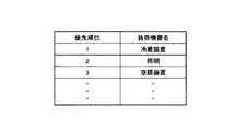
また、本実施形態に係る記憶部153は、図4に示すように、負荷機器名と、優先順位とが関連付けられた優先テーブルを記憶する。また、記憶部153は、図5に示すように、対象優先順位と、料金閾値とが関連付けられた対象順位テーブルを記憶する。なお、これらのテーブルの情報は、負荷機器の利用者によって、予め記憶部153に記憶される。また、これらのテーブルは、後述する処理部154によって参照される。 In addition, as illustrated in FIG. 4, the
処理部154は、記憶部153に記憶されているプログラムに従った処理を行う。また、処理部154は、取得部162と電力制御部164とを備える。 The
取得部162は、電力系統230aから需要家群300aに供給される電力量によって定められる負荷情報を、EMS100aから取得する。具体的に、取得部162は、通信部152を介して、EMS100aから電力料金情報を取得する。 The
電力制御部164は、電力系統230aと解列した後に再連系する際、取得部162によって取得された電力料金情報に基づいて、需要家301内における消費電力を制御する。 このとき、電力制御部164は、電力料金情報に基づいて、照明331、空調装置332、冷蔵装置333、テレビ334、及び蓄熱機器335などの複数の負荷機器の中から、電力の供給を優先すべき負荷機器を選択し、需要家301内における消費電力を制御する。なお、電力系統230aと解列した後に電力系統230aと再連系するケースとしては、電力系統230aが停電から復旧する場合が挙げられる。 The
具体的に、電力制御部164は、取得部162から電力料金情報を取得するとともに、記憶部153の対象順位テーブルを参照し、料金閾値を特定する。このとき、電力制御部164は、料金閾値のうち、電力料金情報によって示される電力料金よりも高く、且つ、電力料金に最も近い料金閾値を特定する。そして、電力制御部164は、特定した料金閾値に対応する対象優先順位を特定する。 Specifically, the
また、電力制御部164は、優先テーブルを参照し、特定した対象優先順位に対応する負荷機器名を選択する。電力制御部164は、選択した負荷機器名に該当する負荷機器に対して、家庭内配電線350との接続を指示するか、又は、起動を指示する。一方、電力制御部164は、選択しなかった負荷機器に対しては、家庭内配電線350との接続を指示しないか、又は、動作の停止を指示する。 Further, the
また、電力制御部164は、負荷機器に対する指示を行った後、遮断器311に対して、電力系統230aと家庭内配電線350との接続を指示する。遮断器311は、この指示に応じて、電力系統230aと家庭内配電線350とを接続し、電力系統230aからの電力が、家庭内配電線350を介して、各負荷機器に供給される。 In addition, after giving an instruction to the load device, the
また、スマートメータ310は、電力系統230aと家庭内配電線350とが接続されて、所定期間(例えば、5分)経過後、ハイブリッドPCS320に対して、再連系を指示する。なお、スマートメータ310は、所定期間を待たずに、ハイブリッドPCS320に対して、すぐに再連系を指示してもよい。 The
(4)スマートメータの動作
次に、需要家制御システム1において、停電が復旧し、需要家301が再連系する際のスマートメータ310の動作を説明する。なお、ここでは、需要家群300aに含まれる需要家301の動作を例に挙げて説明するが、需要家群300bに含まれる需要家301も同様の動作を行うことができる。図6は、スマートメータ310の動作を示すシーケンス図である。(4) Operation of Smart Meter Next, the operation of the
ステップS101において、スマートメータ310の取得部162は、停電から復旧した際、広域通信網90を介して、EMS100aから電力料金情報を取得する。 In step S101, the
ステップS102において、スマートメータ310の電力制御部164は、電力料金情報に基づいて、照明331、空調装置332、冷蔵装置333、テレビ334、及び蓄熱機器335などの複数の負荷機器の中から、電力の供給を優先すべき負荷機器を選択する。 In step S102, the
具体的に、電力制御部164は、取得部162から電力料金情報を取得するとともに、記憶部153の対象順位テーブルを参照し、料金閾値を特定する。そして、電力制御部164は、特定した料金閾値に対応する対象優先順位を特定する。続いて、電力制御部164は、優先テーブルを参照し、特定した対象優先順位に対応する負荷機器名を選択する。 Specifically, the
ステップS103において、電力制御部164は、選択した負荷機器名に該当する負荷機器に対して、家庭内配電線350との接続を指示するか、又は、起動を指示する。一方、電力制御部164は、選択しなかった負荷機器に対しては、家庭内配電線350との接続を指示しないか、又は、動作の停止を指示する。このようにして、スマートメータ310は、電力を供給すべき負荷機器を選択して、需要家301内における消費電力を制御する。 In step S103, the
ステップS104において、電力制御部164は、遮断器311に対して、電力系統230aと家庭内配電線350との接続を指示する。遮断器311は、この指示に応じて、電力系統230aと家庭内配電線350とを接続し、電力系統230aからの電力が負荷機器に供給される。 In step S <b> 104, the
ステップS105において、電力制御部164は、所定期間(例えば、5分)経過後、ハイブリッドPCS320に対して、再連系を指示する。ハイブリッドPCS320は、この指示に応じて、電力系統230a及び家庭内配電線350との再連系を開始する。 In step S105, the
(5)作用及び効果
上述した実施形態によれば、スマートメータ310は、電力系統230aに停電が発生して解列した後に、停電が復旧して再連系する際、EMS100aから取得した電力料金情報に基づいて、電力系統230aから供給可能な電力量を推測して、需要家301内の消費電力を制御する。(5) Operation and Effect According to the above-described embodiment, the
したがって、かかるスマートメータ310によれば、電力系統230aの停電の復旧時において、電力系統230aから供給可能な電力量を考慮して、需要家301内の消費電力を制御するので、電力系統の過負荷状態の発生を抑制することができる。 Therefore, according to the
また、かかるスマートメータ310によれば、全ての負荷機器に電力を供給するのではなく、電力の供給を優先すべき負荷機器を選択して、需要家301内における消費電力を抑制できる。よって、かかるスマートメータ310によれば、利用者にとって重要な負荷機器を優先して、電力を供給することができる。 Further, according to the
[第2実施形態]
次に、本発明の第2実施形態に係る需要家制御システム1の構成について説明する。本実施形態に係る需要家制御システム1の構成は、スマートメータ310の構成を除き第1実施形態に係る需要家制御システム1と同様である。したがって、スマートメータ310の構成について説明する。[Second Embodiment]
Next, the structure of the
(1)スマートメータの構成
本実施形態に係るスマートメータ310は、負荷機器に対して、動作モードを指示し、負荷機器は、スマートメータ310から指示された動作モードに従って動作するように構成されている。(1) Configuration of Smart Meter The
ここで、動作モードとは、負荷機器の消費電力の多寡と対応付けられるものである。つまり、負荷機器は、設定される動作モードによって、消費電力が異なる。本実施形態では、負荷機器の消費電力の大きさに対応する複数の動作モードが予め定められている。 Here, the operation mode is associated with the amount of power consumption of the load device. That is, the load device has different power consumption depending on the set operation mode. In the present embodiment, a plurality of operation modes corresponding to the power consumption of the load device are determined in advance.
また、本実施形態に係るスマートメータ310では、記憶部153が、図7に示すように、複数の動作モードと、それぞれの動作モードに対応する料金閾値とが関連付けられたモードテーブルを記憶する。 Further, in the
動作モードと料金閾値とは、消費電力の少ない動作モードほど、料金閾値が低くなり、消費電力が多い動作モードほど、料金閾値が高くなるという対応関係を有している。図7の例では、動作モードは、番号が大きくなるほど、対応する消費電力が小さく、料金閾値は、番号が大きくなるほど、当該料金閾値は高くなっている。この動作モードと料金閾値との対応関係は、負荷機器毎に予め設定され、記憶部153に記憶されている。 The operation mode and the charge threshold value have a correspondence relationship that the operation mode with lower power consumption has a lower charge threshold value, and the operation mode with higher power consumption has a higher charge threshold value. In the example of FIG. 7, as the number of operation modes increases, the corresponding power consumption decreases, and the charge threshold increases as the number increases. The correspondence between the operation mode and the charge threshold is preset for each load device and stored in the
また、本実施形態に係るスマートメータ310では、電力制御部164は、電力料金情報によって示される電力料金と、予め定められている電力料金の閾値(料金閾値)との比較によって、照明331、空調装置332、冷蔵装置333、テレビ334、及び蓄熱機器335など負荷機器の動作モードを決定することができる。 Further, in the
ここで、料金情報によって示される電力料金は、TOUとRTPの2種類が存在し、RTPの方がTOUよりも送信周期が短く、リアルタイムの需給状況に対応している。このため、電力制御部164は、RTPを所定の送信周期で取得している間は、RTPと料金閾値との比較によって、動作モードを決定し、通信障害等によってRTPを所定の送信周期で取得することができない間は、TOUと料金閾値との比較によって、動作モードを決定してもよい。 Here, there are two types of power charges indicated by the charge information: TOU and RTP. RTP has a shorter transmission cycle than TOU and corresponds to a real-time supply and demand situation. For this reason, the
電力制御部164は、取得部162から電力料金情報を取得して、負荷機器毎の動作モードを決定する。具体的に、電力制御部164は、記憶部153のモードテーブルを参照して、料金閾値のうち、電力料金情報によって示される電力料金よりも高く、且つ、料金情報によって示される電力料金に最も近い料金閾値を特定する。 The
例えば、料金情報によって示される電力料金が図7に示す料金閾値3と料金閾値4との間の値である場合、電力制御部164は、料金閾値4を特定する。更に、電力制御部164は、負荷装置毎に、特定した料金閾値に対応する動作モードを特定する。例えば、図3において料金閾値4が特定された場合、当該料金閾値4に対応する動作モード4が特定されることになる。 For example, when the power rate indicated by the rate information is a value between the
また、図8には、RTPの電力料金における時間遷移の一例が示されている。図8に示すように、電力制御部164は、RTPの電力料金が上昇し、料金閾値を越える度に、動作モードを変更する。このようにして、電力制御部164は、電力料金情報によって示される電力料金に基づいて、動作モードを決定し、決定した動作モードを負荷機器に指示する。また、負荷機器は、指示された動作モードに応じて、動作する。 FIG. 8 shows an example of time transition in the RTP power rate. As shown in FIG. 8, the
ここで、上述した第1実施形態では、スマートメータ310は、電力系統230aと解列した後に再連系する際、EMS100aから送信される電力料金情報に基づいて、需要家301内の消費電力を制御するように構成されていたが、本実施形態に係るスマートメータ310は、電力料金情報を受信すること無く、需要家301内の消費電力を制御する。 Here, in the first embodiment described above, when the
具体的に、本実施形態に係る電力制御部164は、電力系統と解列した後に再連系する際、複数の動作モードの中から、最も消費電力が低い動作モードを選択して、前記需要家内における消費電力を制御する。 Specifically, when the
例えば、電力制御部164は、電力系統230aの停電が復旧して、電力系統230aと接続する際、最も低い動作モードである動作モード4を選択する。また、電力制御部164は、選択した動作モード4で動作するように、負荷機器に指示する。 For example, when the power failure of the
(2)スマートメータの動作
次に、本実施形態に係るスマートメータ310の動作について説明する。なお、以下の動作は、電力系統230aに停電が発生して解列した後に、停電が復旧して再連系する際のスマートメータ310の動作である。図9には、本実施形態に係るスマートメータ310の動作が示されている。(2) Operation of Smart Meter Next, the operation of the
ステップS201において、スマートメータ310では、電力制御部164が、記憶部153のモードテーブルを参照して、最も低い動作モードである動作モード4を選択する。 In step S201, in the
ステップS202において、電力制御部164が、選択した動作モード4で動作するように、それぞれの負荷機器に指示する。このようにして、スマートメータ310は、需要家301内における負荷機器の消費電力が低くなるように制御する。 In step S202, the
ステップS203において、電力制御部164は、遮断器311に対して、電力系統230aと家庭内配電線350との接続を指示する。遮断器311は、この指示に応じて、電力系統230aと家庭内配電線350とを接続し、電力系統230aからの電力が負荷機器に供給される。このとき、負荷機器は、消費電力の最も低い動作モード4で動作を開始する。 In step S <b> 203, the
ステップS204において、電力制御部164は、所定期間(例えば、5分)経過後、ハイブリッドPCS320に対して、再連系を指示する。ハイブリッドPCS320は、この指示に応じて、電力系統230a及び家庭内配電線350との再連系を開始する。 In step S204, the
なお、電力制御部164は、再連系した後、電力料金情報を受信した際に、当該電力料金情報によって示される電力料金に基づいて、複数の動作モードの中から、動作モードを再選択してもよい。さらに、電力制御部164は、需要家301を含む需要家群300aが電力系統230aと再連系が完了した後に、EMS100aからその旨の通知と電力料金情報とを受信した場合、当該電力料金情報によって示される電力料金に基づいて、複数の動作モードの中から、動作モードを再選択してもよい。 The
(3)作用及び効果
本実施形態に係るスマートメータ310によれば、電力系統230aに停電が発生して解列した後に、停電が復旧して再連系する際、最も消費電力量が少ない動作モード(動作モード4)を選択して、需要家301内の負荷機器の消費電力を制御する。(3) Operation and Effect According to the
したがって、かかるスマートメータ310によれば、外部から情報を取得しなくとも、自主的に需要家301内の消費電力を抑制した上で、電力系統230aと接続することができるので、電力系統230aの停電の復旧時において、電力系統230aの過負荷状態の発生を抑制することができる。 Therefore, according to the
[その他の実施形態]
上記のように、本発明は実施形態によって記載したが、この開示の一部をなす論述及び図面はこの発明を限定するものであると理解すべきではない。この開示から当業者には様々な代替実施形態、実施例及び運用技術が明らかとなる。[Other Embodiments]
As mentioned above, although this invention was described by embodiment, it should not be understood that the description and drawing which form a part of this indication limit this invention. From this disclosure, various alternative embodiments, examples and operational techniques will be apparent to those skilled in the art.
上述した第1実施形態においては、負荷情報を電力料金情報として説明したが、かかる負荷情報は、供給可能情報によって示される供給可能電力量と、消費電力情報によって示される消費電力量との間にどれだけ差(需給差)があるかを示す情報であればよく、例えば、供給可能電力量に対する消費電力量の比率などでもよい。かかる場合、料金閾値に変えて、比率に応じた複数の閾値を予め決定しておけばよい。また、消費電力量は、負荷機器が消費する消費電力量から需要家301の分散電源から供給可能な電力量を差し引いたものであってもよい。 In the first embodiment described above, the load information is described as the power charge information. However, the load information is between the suppliable power amount indicated by the suppliable information and the power consumption amount indicated by the power consumption information. Any information indicating how much difference (demand-and-supply difference) exists may be used. For example, it may be a ratio of power consumption to suppliable power. In such a case, instead of the charge threshold value, a plurality of threshold values corresponding to the ratio may be determined in advance. Further, the power consumption may be obtained by subtracting the amount of power that can be supplied from the distributed power source of the
上述した各実施形態においては、分散電源として、太陽電池321や蓄電池322を例に挙げて説明したが、風力発電などの他の電源装置であってもよい。 In each embodiment mentioned above, although the
また、上述した各実施形態において、スマートメータ310の機能は、HEMS(Home Energy Management System)やBEMS(Building and Energy Management System)等、スマートグリッド技術における様々なシステムにおいて適用可能である。 Further, in each of the above-described embodiments, the function of the
また、上述した各実施形態において、遮断器311の機能は、スマートメータ310内に備えていてもよい。 Moreover, in each embodiment mentioned above, the function of the
また、上述した各実施形態において、スマートメータ310の処理部154の機能は、需要家301に別途設けられる他の装置に備えるようにしてもよい。 Moreover, in each embodiment mentioned above, you may make it provide the function of the
このように本発明は、ここでは記載していない様々な実施形態等を包含するということを理解すべきである。したがって、本発明はこの開示から妥当な特許請求の範囲の発明特定事項によってのみ限定されるものである。 Thus, it should be understood that the present invention includes various embodiments and the like not described herein. Therefore, the present invention is limited only by the invention specifying matters in the scope of claims reasonable from this disclosure.
1…需要家制御システム、10…電力系統システム、90…広域通信網、100a乃至100b…EMS、120…処理部、152…通信部、153…記憶部、154…処理部、162…取得部、164…電力制御部、210…発電所、220a乃至220b…変電所、230a乃至230b…電力系統、300a乃至300b…需要家群、301…需要家、310…スマートメータ、311…遮断器、320…ハイブリッドPCS、321…太陽電池、322…蓄電池、331…照明、332…空調装置、333…冷蔵装置、334…テレビ、335…蓄熱機器、350…家庭内配電線、380…家庭内通信回線、400…スマートサーバDESCRIPTION OF
Claims (3)
Translated fromJapanese前記需要家に設けられる負荷機器の消費電力に対応する複数の動作モードが定められており、
前記電力系統と解列した後に再連系する際、前記複数の動作モードの中から、最も消費電力が低い動作モードを選択して、前記需要家内における消費電力を制御する制御部を備えることを特徴とする制御装置。A control device that is provided in a consumer having a power system interconnected with and disconnected from the power system, and that controls power consumed in the consumer,
A plurality of operation modes corresponding to the power consumption of the load equipment provided in the consumer are defined,
When reconnecting after disconnecting from the power system, a control unit that selects an operation mode with the lowest power consumption from the plurality of operation modes and controls power consumption in the consumer is provided. Control device characterized.
前記需要家に設けられる負荷機器の消費電力に対応する複数の動作モードが定められており、
前記電力系統と解列した後に再連系する際、前記複数の動作モードの中から、最も消費電力が低い動作モードを選択して、前記需要家内における消費電力を制御するステップを備えることを特徴とする制御方法。A control method in a control device for controlling power consumed in a consumer, provided in a consumer having a power system interconnected with and disconnected from the power system,
A plurality of operation modes corresponding to the power consumption of the load equipment provided in the consumer are defined,
When reconnecting after disconnecting from the power system, the operation mode includes a step of selecting an operation mode having the lowest power consumption from the plurality of operation modes and controlling power consumption in the consumer. Control method.
Priority Applications (2)
| Application Number | Priority Date | Filing Date | Title |
|---|---|---|---|
| JP2010264389AJP5663280B2 (en) | 2010-11-26 | 2010-11-26 | Control apparatus and control method |
| JP2014163985AJP5801936B2 (en) | 2010-11-26 | 2014-08-11 | Control apparatus and control method |
Applications Claiming Priority (2)
| Application Number | Priority Date | Filing Date | Title |
|---|---|---|---|
| JP2010264389AJP5663280B2 (en) | 2010-11-26 | 2010-11-26 | Control apparatus and control method |
| JP2014163985AJP5801936B2 (en) | 2010-11-26 | 2014-08-11 | Control apparatus and control method |
Related Child Applications (1)
| Application Number | Title | Priority Date | Filing Date |
|---|---|---|---|
| JP2014163985ADivisionJP5801936B2 (en) | 2010-11-26 | 2014-08-11 | Control apparatus and control method |
Publications (2)
| Publication Number | Publication Date |
|---|---|
| JP2012115110A JP2012115110A (en) | 2012-06-14 |
| JP5663280B2true JP5663280B2 (en) | 2015-02-04 |
Family
ID=54056015
Family Applications (2)
| Application Number | Title | Priority Date | Filing Date |
|---|---|---|---|
| JP2010264389AExpired - Fee RelatedJP5663280B2 (en) | 2010-11-26 | 2010-11-26 | Control apparatus and control method |
| JP2014163985AActiveJP5801936B2 (en) | 2010-11-26 | 2014-08-11 | Control apparatus and control method |
Family Applications After (1)
| Application Number | Title | Priority Date | Filing Date |
|---|---|---|---|
| JP2014163985AActiveJP5801936B2 (en) | 2010-11-26 | 2014-08-11 | Control apparatus and control method |
Country Status (1)
| Country | Link |
|---|---|
| JP (2) | JP5663280B2 (en) |
Families Citing this family (7)
| Publication number | Priority date | Publication date | Assignee | Title |
|---|---|---|---|---|
| JP5986858B2 (en)* | 2012-09-20 | 2016-09-06 | 積水化学工業株式会社 | Power management system, power management apparatus, power management method, and program |
| JP5903088B2 (en)* | 2013-10-25 | 2016-04-13 | 中国電力株式会社 | Load control device, load control method and program |
| JP6536002B2 (en)* | 2014-10-02 | 2019-07-03 | 株式会社デンソー | Ampere breaker and power management system |
| JP6562664B2 (en)* | 2015-03-13 | 2019-08-21 | 株式会社日立製作所 | Energy control system |
| CN104899798B (en)* | 2015-06-30 | 2018-12-21 | 天津大学 | A kind of transient state risk control method for the wind power integration system considering spinning reserve |
| JP6665436B2 (en)* | 2015-07-06 | 2020-03-13 | 日本電気株式会社 | CONTROL DEVICE, ITS CONTROL METHOD, AND PROGRAM |
| JP7354657B2 (en)* | 2019-08-01 | 2023-10-03 | 住友電気工業株式会社 | Power control device, power control method, and computer program |
Family Cites Families (11)
| Publication number | Priority date | Publication date | Assignee | Title |
|---|---|---|---|---|
| JPS63117624A (en)* | 1986-11-05 | 1988-05-21 | 株式会社明電舎 | Electric source system controller |
| JP2000013933A (en)* | 1998-06-18 | 2000-01-14 | Nec Eng Ltd | Control switchboard |
| JP3779151B2 (en)* | 2000-12-08 | 2006-05-24 | 株式会社日立製作所 | Incentive power load control method and system |
| EP1263108A1 (en)* | 2001-06-01 | 2002-12-04 | Roke Manor Research Limited | Community energy comsumption management |
| JP2003199249A (en)* | 2001-12-25 | 2003-07-11 | Hitachi Ltd | Operation method and system of power supply network |
| JP4711651B2 (en)* | 2004-08-18 | 2011-06-29 | 三菱電機株式会社 | Distribution system monitoring and control system |
| US7231280B2 (en)* | 2004-12-14 | 2007-06-12 | Costa Enterprises, L.L.C. | Dynamic control system for power sub-network |
| JP2008125295A (en)* | 2006-11-14 | 2008-05-29 | Central Res Inst Of Electric Power Ind | Load selection / blocking method in consumer and load selection / blocking device in consumer |
| JP4628386B2 (en)* | 2007-03-20 | 2011-02-09 | 財団法人電力中央研究所 | Distributed power supply operating status detection device, watt-hour meter, and distribution system control device |
| JP5410037B2 (en)* | 2007-05-30 | 2014-02-05 | 三洋電機株式会社 | Grid interconnection device and grid interconnection system |
| JP5110603B2 (en)* | 2008-08-13 | 2012-12-26 | 独立行政法人産業技術総合研究所 | Direct load control system |
- 2010
- 2010-11-26JPJP2010264389Apatent/JP5663280B2/ennot_activeExpired - Fee Related
- 2014
- 2014-08-11JPJP2014163985Apatent/JP5801936B2/enactiveActive
Also Published As
| Publication number | Publication date |
|---|---|
| JP2014241718A (en) | 2014-12-25 |
| JP5801936B2 (en) | 2015-10-28 |
| JP2012115110A (en) | 2012-06-14 |
Similar Documents
| Publication | Publication Date | Title |
|---|---|---|
| JP5801936B2 (en) | Control apparatus and control method | |
| JP7724940B2 (en) | Systems and methods for creating dynamic nanogrids and aggregating power consumers to participate in energy markets | |
| US10637241B2 (en) | System and method for intelligent static transfer switch with smart home power management | |
| JP5663645B2 (en) | Control apparatus and control method | |
| US8560135B2 (en) | Energy management system, energy management apparatus, and energy management method | |
| JP6893906B2 (en) | Management method, control device and communication processing device | |
| JP5660863B2 (en) | Control apparatus and control method | |
| JP5960958B2 (en) | Power management system | |
| JP5946919B2 (en) | Management system, management method and equipment | |
| JP6158562B2 (en) | Power conversion apparatus, control system, and control method | |
| WO2020161765A1 (en) | Direct-current power supply system | |
| JP2013017284A (en) | Power control system, electric apparatus and charge/discharge control section | |
| JP2012115109A (en) | Controller and control method | |
| CN116542492B (en) | Energy information processing method and device for household energy storage system | |
| JP6199640B2 (en) | Control device, control system, distribution board and control method | |
| US12407169B2 (en) | Energy coupling method and system for household energy storage | |
| JP7579151B2 (en) | Power System | |
| US20250167586A1 (en) | Energy coupling method and system for household energy storage | |
| JP6434097B2 (en) | Control device, control system, distribution board and control method | |
| CA2948243C (en) | System and method for intelligent static transfer switch with smart home power management |
Legal Events
| Date | Code | Title | Description |
|---|---|---|---|
| A621 | Written request for application examination | Free format text:JAPANESE INTERMEDIATE CODE: A621 Effective date:20131015 | |
| A977 | Report on retrieval | Free format text:JAPANESE INTERMEDIATE CODE: A971007 Effective date:20140530 | |
| A131 | Notification of reasons for refusal | Free format text:JAPANESE INTERMEDIATE CODE: A131 Effective date:20140610 | |
| A521 | Request for written amendment filed | Free format text:JAPANESE INTERMEDIATE CODE: A523 Effective date:20140811 | |
| TRDD | Decision of grant or rejection written | ||
| A01 | Written decision to grant a patent or to grant a registration (utility model) | Free format text:JAPANESE INTERMEDIATE CODE: A01 Effective date:20141118 | |
| A61 | First payment of annual fees (during grant procedure) | Free format text:JAPANESE INTERMEDIATE CODE: A61 Effective date:20141208 | |
| R150 | Certificate of patent or registration of utility model | Ref document number:5663280 Country of ref document:JP Free format text:JAPANESE INTERMEDIATE CODE: R150 | |
| LAPS | Cancellation because of no payment of annual fees |