JP5660413B2 - Vehicle side connector - Google Patents
Vehicle side connectorDownload PDFInfo
- Publication number
- JP5660413B2 JP5660413B2JP2013540696AJP2013540696AJP5660413B2JP 5660413 B2JP5660413 B2JP 5660413B2JP 2013540696 AJP2013540696 AJP 2013540696AJP 2013540696 AJP2013540696 AJP 2013540696AJP 5660413 B2JP5660413 B2JP 5660413B2
- Authority
- JP
- Japan
- Prior art keywords
- connector
- vehicle
- main body
- fitted
- connector main
- Prior art date
- Legal status (The legal status is an assumption and is not a legal conclusion. Google has not performed a legal analysis and makes no representation as to the accuracy of the status listed.)
- Expired - Fee Related
Links
- 238000003780insertionMethods0.000claimsdescription21
- 230000037431insertionEffects0.000claimsdescription21
- 230000002093peripheral effectEffects0.000claimsdescription12
- 229920003002synthetic resinPolymers0.000claimsdescription7
- 239000000057synthetic resinSubstances0.000claimsdescription7
- 238000000465mouldingMethods0.000description13
- 238000010079rubber tappingMethods0.000description9
- 238000004519manufacturing processMethods0.000description8
- 239000011295pitchSubstances0.000description8
- XLYOFNOQVPJJNP-UHFFFAOYSA-NwaterSubstancesOXLYOFNOQVPJJNP-UHFFFAOYSA-N0.000description4
- 230000000694effectsEffects0.000description3
- 238000007493shaping processMethods0.000description3
- 238000000034methodMethods0.000description2
- 230000004308accommodationEffects0.000description1
- 238000005219brazingMethods0.000description1
- 239000012141concentrateSubstances0.000description1
- 239000013013elastic materialSubstances0.000description1
- 238000000605extractionMethods0.000description1
- 230000013011matingEffects0.000description1
- 230000000149penetrating effectEffects0.000description1
- 239000011435rockSubstances0.000description1
- 238000003466weldingMethods0.000description1
Images


Classifications
- Y—GENERAL TAGGING OF NEW TECHNOLOGICAL DEVELOPMENTS; GENERAL TAGGING OF CROSS-SECTIONAL TECHNOLOGIES SPANNING OVER SEVERAL SECTIONS OF THE IPC; TECHNICAL SUBJECTS COVERED BY FORMER USPC CROSS-REFERENCE ART COLLECTIONS [XRACs] AND DIGESTS
- Y02—TECHNOLOGIES OR APPLICATIONS FOR MITIGATION OR ADAPTATION AGAINST CLIMATE CHANGE
- Y02T—CLIMATE CHANGE MITIGATION TECHNOLOGIES RELATED TO TRANSPORTATION
- Y02T10/00—Road transport of goods or passengers
- Y02T10/60—Other road transportation technologies with climate change mitigation effect
- Y02T10/70—Energy storage systems for electromobility, e.g. batteries
Landscapes
- Arrangement Or Mounting Of Propulsion Units For Vehicles (AREA)
- Connector Housings Or Holding Contact Members (AREA)
- Electric Propulsion And Braking For Vehicles (AREA)
Description
Translated fromJapanese本発明は、充電の際に充電用コネクタが嵌合される車両側コネクタに関する。 The present invention relates to a vehicle-side connector into which a charging connector is fitted during charging.
例えば、電気自動車などの車両に搭載されたバッテリから延びる電線の端末に接続されて、車両のボディに取り付けられる車両側コネクタとして、特許文献1に記載のものが知られている。この車両側コネクタは、充電用コネクタに嵌合される合成樹脂製のコネクタ本体部と、コネクタ本体部の外周面から外方に張り出すようにコネクタ本体部と一体に設けられた合成樹脂製の取付板とを備えて構成されている。この取付板には、取付板を板厚方向に貫通するボルト挿通孔が設けられており、このボルト挿通孔に締結ボルトを挿通させて、締結ボルトを車体に設けられたボルト締結孔に締め込むことで、車両側コネクタが車体に取り付け固定されるようになっている。 For example, the thing of patent document 1 is known as a vehicle side connector connected to the terminal of the electric wire extended from the battery mounted in vehicles, such as an electric vehicle, and attached to the body of a vehicle. This vehicle-side connector is made of a synthetic resin connector body that is fitted to the charging connector, and a synthetic resin integrally provided with the connector body so as to project outward from the outer peripheral surface of the connector body. And an attachment plate. The mounting plate is provided with a bolt insertion hole that penetrates the mounting plate in the thickness direction. The fastening bolt is inserted into the bolt insertion hole, and the fastening bolt is tightened into the bolt fastening hole provided in the vehicle body. Thus, the vehicle-side connector is attached and fixed to the vehicle body.
(発明が解決しようとする課題)
ところで、車体におけるボルト締結孔間のピッチは、車両を製造するメーカーや車種などにより、様々な大きさに設定される。したがって、取付板におけるボルト挿通孔間のピッチも、ボルト締結孔間のピッチに合わせて変更することになり、コネクタ本体部の部分の規格は同一であっても、車種に合わせてボルト挿通孔間のピッチが異なる車両側コネクタを複数用意する必要がある。さらに、車両を製造するメーカーや車種などによっては、コネクタ本体部における充電用コネクタが嵌合される側の開口部分を閉止する蓋部を備えている場合があり、蓋部の有無も含めるとさらに多くの車両側コネクタを用意する必要がある。このため、変更が生じる毎に、コネクタ本体部及び取付板を一体に成形する成形金型を製造することになり、製造コストが高くなってしまう。
本発明は上記のような事情に基づいて完成されたものであって、コネクタ本体部を共用化することで製造コストの低減を図ることを目的とする。(Problems to be solved by the invention)
By the way, the pitch between the bolt fastening holes in the vehicle body is set to various sizes depending on the manufacturer of the vehicle and the vehicle type. Therefore, the pitch between the bolt insertion holes in the mounting plate will also be changed according to the pitch between the bolt fastening holes. It is necessary to prepare a plurality of vehicle side connectors having different pitches. Furthermore, depending on the manufacturer of the vehicle, the vehicle type, etc., there may be provided a lid portion that closes the opening portion on the side where the charging connector is fitted in the connector main body portion, and further including the presence or absence of the lid portion. It is necessary to prepare many vehicle side connectors. For this reason, whenever a change arises, it will manufacture the shaping | molding die which shape | molds a connector main-body part and an attachment board integrally, and a manufacturing cost will become high.
The present invention has been completed based on the above situation, and an object thereof is to reduce the manufacturing cost by sharing the connector main body.
(課題を解決するための手段)
上記の目的を達成するための手段として本発明は、車体にボルトを締め付けることで固定され、車両のバッテリに充電する際に充電用コネクタと嵌合される車両側コネクタであって、前記充電用コネクタが嵌合される合成樹脂製のコネクタ本体部と、前記ボルトが挿通可能なボルト挿通孔を有し、前記ボルト挿通孔に前記ボルトを挿通させて前記車体に締め付けることで前記車体に固定される合成樹脂製の取付部とを備え、前記取付部は前記コネクタ本体部に対して組み付けられて固定されているところに特徴を有する。
例えば、車両が異なると、車体におけるボルトを締め付ける位置が変更となり、取付部におけるボルト挿通孔間のピッチを変更しなければならない場合がある。このため、コネクタ本体部と取付部とが一体に形成された車両側コネクタの場合、コネクタ本体部を含めて交換する必要がある。ところが、上記の車両側コネクタによると、形状が異なる複数の取付部の中から各車体に合わせた取付部を選択し、コネクタ本体部を共有化させることにより、ボルト挿通孔間のピッチが異なる様々な車両に車両側コネクタを対応させることができる。すなわち、取付部のみを成形する成形金型を作成して、取付部のみを各車両に対応させて成形することにより、様々な車両に対して車両側コネクタ10を対応させることできる。これにより、取付部とコネクタ本体部とを一体に成形する成形金型を作成して対応する場合に比べて、成形金型の生産コストを低減させることができる。(Means for solving the problem)
As a means for achieving the above object, the present invention provides a vehicle-side connector that is fixed to a vehicle body by tightening a bolt, and is fitted to a charging connector when charging a vehicle battery. A connector body portion made of a synthetic resin to which a connector is fitted and a bolt insertion hole through which the bolt can be inserted. The bolt is inserted into the bolt insertion hole and fastened to the vehicle body to be fixed to the vehicle body. And a mounting portion made of a synthetic resin. The mounting portion is assembled and fixed to the connector main body.
For example, if the vehicle is different, the position for tightening the bolts in the vehicle body may be changed, and the pitch between the bolt insertion holes in the mounting portion may have to be changed. For this reason, in the case of a vehicle-side connector in which the connector main body portion and the attachment portion are integrally formed, it is necessary to replace the connector main body portion. However, according to the above-described vehicle-side connector, various pitches between the bolt insertion holes can be varied by selecting a mounting portion matched to each vehicle body from a plurality of mounting portions having different shapes and sharing the connector main body portion. A vehicle-side connector can be made to correspond to a simple vehicle. That is, the
本発明の実施の態様として、以下の構成が好ましい。
前記取付部は、板状に形成された取付板と、この取付板を前後方向に貫通して形成され、前記コネクタ本体部が後方から内部に嵌合されると共に、前記充電用コネクタが前方から嵌合される収容部とを備え、前記コネクタ本体部の外面には、前記取付板と面接触可能な突出片が突出して形成されており、前記コネクタ本体部と前記取付部とは、前記突出片を前記取付板に後方から面接触させて、後方から複数の締結部材を前記突出片に挿通させて前記取付板に締め付けることで一体に組み付けられている構成としてもよい。The following configuration is preferable as an embodiment of the present invention.
The attachment portion is formed in a plate-like attachment plate and through the attachment plate in the front-rear direction, the connector main body portion is fitted from the rear to the inside, and the charging connector is from the front And a protruding piece that can come into surface contact with the mounting plate is formed on the outer surface of the connector main body portion, and the connector main body portion and the mounting portion are provided with the protruding portion. It is good also as a structure assembled | attached integrally by making a piece surface-contact with the said mounting plate from back, and inserting a some fastening member into the said protrusion piece from the back, and fastening to the said mounting plate.
このような構成によると、複数の締結部材によってコネクタ本体部と取付部とを一体に組み付けることができるので、車両側コネクタに対して充電用コネクタが挿抜される際に、取付部からコネクタ本体部が外れてしまうことを防止することができる。
また、車両側コネクタから充電用コネクタを抜き取る際に、充電用コネクタが正規の姿勢よりも傾いた状態で引き抜かれると、コネクタ本体部と取付部との間の締結部分に引き抜きに伴う応力が集中する。ところが、上記のような構成によると、突出片を取付板に後方から面接触させてコネクタ本体部と取付部とを一体に組み付けているので、引き抜きに伴う応力を締結部分と面接触部分とに分散することができる。これにより、取付部に対してコネクタ本体部を前方から組み付けるものに比べて、充電用コネクタの引き抜きに伴って、取付部からコネクタ本体部が外れてしまうことを防止することができる。According to such a configuration, the connector main body portion and the attachment portion can be integrally assembled by a plurality of fastening members. Therefore, when the charging connector is inserted into and removed from the vehicle-side connector, the connector main body portion is removed from the attachment portion. Can be prevented from coming off.
Also, when the charging connector is pulled out from the vehicle-side connector, if the charging connector is pulled out from the normal posture, the stress associated with the pulling is concentrated on the fastening portion between the connector body and the mounting portion. To do. However, according to the configuration as described above, since the protruding piece is brought into surface contact with the mounting plate from the rear side and the connector main body portion and the mounting portion are assembled together, the stress accompanying pulling is applied to the fastening portion and the surface contact portion. Can be dispersed. Thereby, compared with what attaches a connector main-body part with respect to an attaching part from the front, it can prevent that a connector main-body part remove | deviates from an attaching part with the extraction of a charging connector.
前記突出片には、前記取付板に設けられた被位置決め部と嵌合可能な位置決め部が形成されている構成としてもよい。
このような構成によると、突出片を取付板に後方から面接触させてコネクタ本体部と取付部とを一体に組み付ける際に、取付板の被位置決め部と突出片の位置決め部を嵌合させることで、取付部と突出片とを位置ずれさせることなく面接触させることができる。これにより、突出片に締結部材を挿通させて取付板に締結部材を締め付ける際の作業効率を向上させることができる。The projecting piece may have a configuration in which a positioning portion that can be fitted to a positioned portion provided on the mounting plate is formed.
According to such a configuration, when the projecting piece is brought into surface contact with the mounting plate from the rear and the connector main body portion and the mounting portion are assembled together, the positioning portion of the mounting plate and the positioning portion of the protruding piece are fitted together. Thus, the mounting portion and the projecting piece can be brought into surface contact without being displaced. Thereby, the work efficiency at the time of fastening a fastening member to a mounting plate by inserting a fastening member in a protrusion piece can be improved.
前記コネクタ本体部と前記充電用コネクタとが正規嵌合した際に、前記充電用コネクタの外周面と前記コネクタ本体部の内周面とに全周に亘って密着するシールリングを備えている構成としてもよい。
車両側コネクタは、一般に、車体の外側に取り付けられているため、車両側コネクタと充電用コネクタとを嵌合させて充電を行っている間に、雨や雪などが降ると、車両側コネクタと充電用コネクタとの間から水が浸入する虞がある。ところが、上記のような構成によると、充電用コネクタを内部に収容するコネクタ本体部の内側にコネクタ本体部の内周面と充電用コネクタの外周面とに密着するシールリングを装着しているので、車両側コネクタと充電用コネクタとの間から雨水などが浸入することを防止することができる。When the connector main body and the charging connector are properly fitted, a structure is provided that includes a seal ring that closely adheres to the outer peripheral surface of the charging connector and the inner peripheral surface of the connector main body. It is good.
Since the vehicle-side connector is generally attached to the outside of the vehicle body, if rain or snow falls while the vehicle-side connector and the charging connector are fitted and charged, the vehicle-side connector There is a risk that water may enter from between the charging connector. However, according to the configuration as described above, the seal ring that is in close contact with the inner peripheral surface of the connector main body and the outer peripheral surface of the charging connector is mounted inside the connector main body that accommodates the charging connector. Further, rainwater or the like can be prevented from entering between the vehicle-side connector and the charging connector.
前記取付部は、前記充電用コネクタが前方から嵌合されると共に、前記コネクタ本体部が後方から内部に嵌合される収容部を備えており、前記シールリングは、前記収容部と前記コネクタ本体部とが前後方向に互いに対向する部分において前後両側から挟持されている構成としてもよい。
収容部とコネクタ本体部とが一体に形成されている場合には、収容部の前端開口からシールリングを挿入して、治具などを用いることでシールリングを収容部の奥部に配置するため、作業性が悪い。ところが、本実施形態によると、取付部とコネクタ本体部とを組み付ける際に、収容部とコネクタ本体部とが互いに対向する部分にシールリングを配置することができるので、シールリングを組み付ける作業効率を向上させることができる。
また、取付部とコネクタ本体部とが別体とされていると、収容部とコネクタ本体部との界面から雨水などが浸入する虞がある。ところが、シールリングが収容部とコネクタ本体部とによって前後両側から挟持されているので、収容部とコネクタ本体部との界面から水などが浸入することを防止することができる。The mounting portion includes a housing portion in which the charging connector is fitted from the front and the connector main body portion is fitted from the rear to the inside, and the seal ring includes the housing portion and the connector main body. It is good also as a structure clamped from the front and back both sides in the part which mutually opposes in the front-back direction.
When the housing part and the connector main body part are integrally formed, a seal ring is inserted from the front end opening of the housing part, and the seal ring is disposed at the back of the housing part by using a jig or the like. The workability is bad. However, according to the present embodiment, when the mounting portion and the connector main body portion are assembled, the seal ring can be disposed at a portion where the housing portion and the connector main body portion face each other, so that the work efficiency of assembling the seal ring is improved. Can be improved.
In addition, if the mounting portion and the connector main body are separated, rainwater or the like may enter from the interface between the housing portion and the connector main body. However, since the seal ring is sandwiched between the front and rear sides by the housing portion and the connector main body portion, it is possible to prevent water and the like from entering from the interface between the housing portion and the connector main body portion.
前記コネクタ本体部における前記充電用コネクタが嵌合される開口部分を閉止する蓋部を備え、前記蓋部は、前記取付部に設けられている構成としてもよい。
車種などの違いによって、コネクタ本体部の開口部分を閉止する蓋部の有無が異なるため、コネクタ本体部の開口縁部に蓋部が設けられている場合には、蓋部の有無により二種類のコネクタ本体部を用意する必要がある。ところが、上記の構成によると、コネクタ本体部と着脱可能な取付部に蓋部が設けられているので、コネクタ本体部を共有化して、取付部のみを交換することで蓋部の有無に対応させることできる。これにより、成形金型などの製造コストを低減させることができる。It is good also as a structure provided with the cover part which closes the opening part by which the said connector for charge in the said connector main-body part is fitted, and the said cover part is provided in the said attaching part.
Depending on the type of vehicle, etc., the presence or absence of a lid that closes the opening of the connector body differs, so if there is a lid on the opening edge of the connector body, there are two types depending on the presence or absence of the lid It is necessary to prepare a connector body. However, according to the above configuration, since the lid portion is provided on the connector main body portion and the detachable attachment portion, the connector main body portion is shared, and only the attachment portion is exchanged so as to correspond to the presence or absence of the lid portion. I can. Thereby, manufacturing costs, such as a shaping die, can be reduced.
(発明の効果)
本発明によれば、コネクタ本体部を共用化することで製造コストを低減させることができる。(Effect of the invention)
According to the present invention, the manufacturing cost can be reduced by sharing the connector main body.
<実施形態1>
本発明の実施形態1について図1乃至図12を参照して説明する。
本実施形態の車両側コネクタ10は、電気自動車などの車両に搭載されたバッテリから延びる図示しない電線の端末に接続されて、車両の図示しないボディに固定され、バッテリに充電を行う際に、外部電源に接続された図示しない充電用コネクタが前方から嵌合される。<Embodiment 1>
Embodiment 1 of the present invention will be described with reference to FIGS.
The vehicle-
車両側コネクタ10は、図5に示すように、車両のボディに固定される取付部20と、取付部20と別体に形成されたコネクタ本体部50とを備えている。そして、取付部20の後方からコネクタ本体部50を組み付けることで、車両側コネクタ10が構成されている。 As shown in FIG. 5, the vehicle-
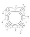
取付部20は、合成樹脂製であって、図6、図7及び図12に示すように、略方形の平板状をなす取付板21と、この取付板21を板厚方向である前後方向に貫通して形成された収容部22とを備えている。 The mounting
取付板21の四隅には、中央にボルト挿通孔23Aが形成されたカラー23が装着されており、ボルト挿通孔23Aに図示しない締結ボルトを挿通させ、車両のボディに設けられた図示しないボルト締結孔に締結ボルトを締め込み、取付板21がボディに固定されることで、車両側コネクタ10が車両に固定されるようになっている。
取付板21の後面には、複数のねじ締結穴24が形成されている。ねじ締結穴24は、上部に位置するカラー23の下方に1つずつ配されたものと、下部に位置する2つのカラー23の間に配された2つとを合わせて、合計4箇所に形成されており、後方からタッピングねじ(本発明の「締結部材」の一例)25が締め付け可能とされている。 A plurality of screw fastening holes 24 are formed on the rear surface of the mounting
収容部22は、略円筒形状をなし、取付板21の前面から前方に突出して形成されている。また、収容部22は、前後方向に開口して形成されており、前方から充電用コネクタが内部に嵌合可能に形成されている。 The
収容部22の後端開口縁部には、前方に向かって凹んだ嵌合溝26が全周に亘って形成されており、嵌合溝26の内側には収容部側取付溝27が形成されている。収容部側取付溝27は、嵌合溝26に沿って形成されており、嵌合溝26の深さ寸法よりも浅く形成されている。このため、収容部22の後端開口縁部は、全周に亘って段付き状に形成されている。 A
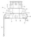
収容部22の外面における左側部分には、略円形平板状をなす蓋部28が保持されている。蓋部28は、収容部22の前端開口を閉止可能に形成されており、収容部22の前端開口を閉止する閉止位置(図示せず)から収容部22の前端開口が開放された開放位置(図1参照)までの間を回動可能とされている。また、収容部22の外面における右側部分には、蓋部28の右側端部を係止するロック部29が形成されており、ロック部29が蓋部28の右側端部を係止することで蓋部28が閉止位置に保持されるようになっている。 A
コネクタ本体部50は、図5及び図12に示すように、前方に向かって開口するフード部51と、フード部51の奥部に設けられた奥壁51Aを前後方向に貫通する端子保持部52とを備えて構成されている。 As shown in FIGS. 5 and 12, the connector
フード部51は、断面略円筒状をなし、内部に充電用コネクタが嵌合可能に形成されている。また、フード部51の前端開口縁部は、取付部20の収容部22における嵌合溝26に後方から嵌合可能に形成されており、取付部20の後方にコネクタ本体部50が正規に組み付けられて、フード部51の前端開口縁部が収容部22の嵌合溝26に嵌合されると、図5に示すように、収容部22とフード部51とが一体となって車両側フード部70が構成されるようになっている。 車両側フード部70内には、充電用コネクタが前方から嵌合可能とされ、車両側フード部70内に充電用コネクタが正規に嵌合されると、充電用コネクタの先端部が車両側フード部70の奥部(フード部51の奥部)まで挿入されるように設定されている。なお、本願明細書において、図示省略されているが、充電用コネクタと車両側コネクタ10との間には、ロック機構が設けられている。 The
フード部51の前端開口縁部には、図12に示すように、弾性材からなるシールリングRが装着されたフード部側取付溝53が形成されている。フード部側取付溝53は、後方に向かって凹んだ形態をなし、フード部51の内周面に沿うように全周に亘って形成されている。 As shown in FIG. 12, a hood portion
フード部側取付溝53は、取付部20の収容部22における収容部側取付溝27と前後方向に対向する位置に形成されており、図5に示すように、フード部51の前端開口縁部が収容部22の嵌合溝26に嵌合されると、シールリングRが収容部側取付溝27とフード部側取付溝53とによって前後両側から挟持され、車両側フード部70における前後方向略中央部の位置にシールリングRが配されるようになっている。 The hood portion
一方、シールリングRは、断面山形状をなす環状に形成されている。また、シールリングRの前後方向中央部である山形状の頭頂部R1は、内側に向かって張り出した形態をなしている。車両側フード部70(フード部51)内に充電用コネクタが嵌合されると、シールリングRの山形状の頭頂部R1が充電用コネクタの外周面に密着し、シールリングRの前後方向両端部がフード部51の内周面に密着することで、車両側コネクタ10と充電用コネクタとの間から水などが浸入することを防止するようになっている。 On the other hand, the seal ring R is formed in an annular shape having a mountain shape in cross section. Moreover, the mountain-shaped top part R1 which is the center part in the front-rear direction of the seal ring R has a form projecting inward. When the charging connector is fitted into the vehicle-side hood portion 70 (hood portion 51), the mountain-shaped top portion R1 of the seal ring R is brought into close contact with the outer peripheral surface of the charging connector, and both ends of the seal ring R in the front-rear direction. When the portion is in close contact with the inner peripheral surface of the
また、フード部側取付溝53の深さ寸法は、収容部側取付溝27とほぼ同じ深さ寸法に形成されており、シールリングRが収容部側取付溝27とフード部側取付溝53とによって前後両側から挟持されると、フード部側取付溝53にシールリングRの後端部が嵌り込むと共に、収容部側取付溝27にシールリングRの前端部が嵌り込み、シールリングRの前後両端部が全周に亘って保持されるようになっている。 Further, the depth dimension of the hood portion
フード部51の外周面には、図8に示すように、側方に向かって張り出す平板状の突出片54が形成されている。
突出片54は、フード部51の外周面に全周亘って形成されており、取付部20とコネクタ本体部50とが正規に組み付けられると取付板21の後面に面接触するように設定されている。また、突出片54には、同突出片54を前後方向に貫通して形成されたねじ挿通孔55が複数(本実施形態では4つ)形成されている。ねじ挿通孔55は、取付板21のねじ締結穴24に対応して形成されており、取付板21に突出片54を面接触させた後、タッピングねじ25をねじ挿通孔55に挿通させて、取付板21のねじ締結穴24に締め込むことで、図3乃至図5に示すように、取付部20とコネクタ本体部50とが一体に組み付けられている。As shown in FIG. 8, a flat plate-like projecting
The protruding
また、突出片54の上下左右の端縁には、図10乃至図12に示すように、前方に向かって突出する位置決め片(本発明の「位置決め部」の一例)56が形成されている。一方、取付板21の上下左右の端縁には、位置決め片56を内部に嵌合可能な位置決め凹部(本発明の「被位置決め部」の一例)30が形成されている。コネクタ本体部50のフード部51の前端開口縁部が取付部20の収容部22の嵌合溝26に嵌合されると共に、位置決め片56が位置決め凹部30内に嵌合されることで、取付部20とコネクタ本体部50とが位置ずれすることなく組み付けられるようになっている。これにより、ねじ挿通孔55に挿通させたタッピングねじ25を取付板21のねじ締結穴24に確実に締め込むことができる。 Further, as shown in FIGS. 10 to 12, positioning pieces (an example of the “positioning portion” of the present invention) 56 that protrudes forward are formed on the upper, lower, left, and right edges of the protruding
また、突出片54の下部に位置する位置決め片56及び取付板21の下部に位置する位置決め凹部30は、上部及び左右に位置する位置決め片56や上部及び左右に位置する位置決め凹部30に比べて、小さく形成されている。これにより取付部20に対してコネクタ本体部50を上下反転させて組み付けるなど、誤組付けを防止することができる。 Further, the
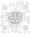
端子保持部52は、図10乃至図12に示すように、フード部51の奥壁51Aから前方に突出する複数(本実施形態では7つ)の端子収容筒部57を備えて構成されている。端子収容筒部57は、いずれも略円筒形状をなしており、充電用コネクタに設けられた図示しない小フード部内に一括して嵌合可能に形成されている。充電用コネクタと車両側コネクタ10とが正規に嵌合されると、小フード部が車両側フード部70と端子収容筒部57との間に嵌り込み、小フード部と端子収容筒部57とが嵌合される。 As shown in FIGS. 10 to 12, the
端子収容筒部57の内部には、前後方向に貫通するキャビティ58が形成されている。キャビティ58には、図示しない車両側端子が保持されるようになっており、小フード部と端子収容筒部57とが正規に嵌合されると、小フード部内に設けられた図示しない外部電源側端子と車両側端子とが導通可能に接続されるようになっている。 A
本実施形態は以上のような構成であって、車両側コネクタ10の組み付け手順を簡単に説明すると共に、その作用・効果を説明する。
まず、図10乃至図12に示すように、取付部20と、シールリングRがフード部側取付溝53に嵌着されたコネクタ本体部50とを準備し、取付部20の収容部22における嵌合溝26にコネクタ本体部50のフード部51における前端開口縁部を後方から嵌合させると共に、取付部20の取付板21における位置決め凹部30内にコネクタ本体部50の突出片54における位置決め片56を後方から嵌合させることで、取付部20の後側にコネクタ本体部50が位置ずれすることなく組み付けられる。The present embodiment has the above-described configuration. The procedure for assembling the vehicle-
First, as shown in FIGS. 10 to 12, a mounting
ここで、嵌合溝26にフード部51の前端開口縁部が正規に嵌合されると、取付部20の取付板21の後面にコネクタ本体部50の突出片54が面接触し、それと同時に、フード部側取付溝53に嵌着されたシールリングRの前端部が取付部20の収容部22における収容部側取付溝27に嵌り込こんで、シールリングRがフード部側取付溝53と収容部側取付溝27とによって前後方向から挟持される。これにより、シールリングRは、フード部側取付溝53の後側内面と収容部側取付溝27の前側内面とに密着し、取付部20とコネクタ本体部50との界面から水などが浸入することを防止することができる。 Here, when the front end opening edge of the
次に、突出片54の各ねじ挿通孔55にタッピングねじ25を挿通させて、複数のタッピングねじ25を取付板21の各ねじ締結穴24に締め付けることで、取付部20とコネクタ本体部50とが一体に組み付けられる。これにより、車両側コネクタ10に対して充電用コネクタが挿抜される際に、取付部20からコネクタ本体部50が外れてしまうことを防止することができる。
ところで、車両側コネクタ10から充電用コネクタを抜き取る際に、充電用コネクタが正規の姿勢よりも傾いた状態で引き抜かれると、コネクタ本体部50と取付部20との間の締結部分であるねじ締結穴24とタッピングねじ25との間に引き抜きに伴う応力が集中する。ところが、本実施形態によると、突出片54を取付板21に後方から面接触させた状態でコネクタ本体部50と取付部20とが一体に組み付けられているので、充電用コネクタの引き抜きに伴う応力を締結部分と面接触部分である取付板21及び突出片54とに分散することができる。これにより、取付部に対してコネクタ本体部を前方から組み付けるものに比べて、コネクタ本体部50と取付部20との間の締結部分に応力が集中することを抑制し、充電用コネクタの引き抜きに伴って、取付部20からコネクタ本体部50が外れてしまうことを防止することができる。Next, the tapping
By the way, when the charging connector is pulled out from the vehicle-
最後に、電線の端末に接続された図示しない車両側端子をコネクタ本体部50の各キャビティ58内に後方から挿入することで車両側コネクタ10が完成する。 Finally, the vehicle-
ところで、車両側コネクタ10が固定されるボディに設けられた図示しないボルト締結孔間のピッチは、車両を製造するメーカーや車種などにより、様々な大きさに設定されている。このため、充電用コネクタが嵌合されるコネクタ本体部50におけるフード部51や端子保持部52の規格は同一であっても、取付板21におけるボルト挿通孔23Aの位置を変更する必要がある。したがって、カラー23が装着された取付部とコネクタ本体部とが一体に形成された従来の車両側コネクタの場合、取付部だけでなく、コネクタ本体部を含めて交換する必要がある。ところが、本実施形態によると、形状の異なる複数の取付部の中から車両のボルト締結孔に対応する取付部20を選択し、コネクタ本体部50を共有化させることにより、様々な車両に対して車両側コネクタ10を対応させることができる。すなわち、取付部20のみを成形する成形金型を作成して、取付部20のみを各車両に対応させて成形することにより、様々な車両に対して車両側コネクタ10を対応させることができる。これにより、取付部とコネクタ本体部とを一体に成形する成形金型を作成して対応する場合に比べて、成形金型の生産コストを低減させることができる。 By the way, the pitch between bolt fastening holes (not shown) provided in the body to which the vehicle-
<実施形態2>
実施形態2について図13及び図14を参照して説明する。
実施形態2の取付部120は、図13及び図14に示すように、実施形態1における取付板21の形状を変更したものであって、実施形態1と共通する構成、作用、および効果については重複するため、その説明を省略する。また、実施形態1と同じ構成については実施形態1の符号の数字に100を足した数字を符号として用いるものとする。<Embodiment 2>
A second embodiment will be described with reference to FIGS. 13 and 14.
As shown in FIGS. 13 and 14, the mounting
実施形態2の取付部120の取付板121は、実施形態1の取付板21よりも一回り大きく形成されている。取付板121の四隅には、実施形態1の取付板21と同様に、ボルト挿通孔123Aが形成されたカラー123が装着されている。すなわち、実施形態2のボルト挿通孔123A間の大きさは、実施形態1のボルト挿通孔23A間の大きさよりも大きくなっており、車両のボディに設けられた図示しないボルト締結孔のピッチが大きいものに対応させることができるようになっている。なお、コネクタ本体部50は、取付部120にも共用化して組み付けられ、タッピングねじ25を締め付けることで、図14に示すように、取付部120とコネクタ本体部50とが一体に組み付けられるようになっている。
また、コネクタ本体部50の位置決め片56と対応する位置には、取付板121を板厚方向に貫通する位置決め孔(本発明の「被位置決め部」の一例)130が形成されており、この位置決め孔130に位置決め片56を嵌合させることで、取付部120にコネクタ本体部50が位置ずれすることなく、組み付けられるようになっている。
また、取付部120には、実施形態1の収容部22の左側に設けられた蓋部28と右側に設けられたロック部29が設けられていない構成となっており、車種などの違いによって、車両側フード部70の前端開口を塞ぐ必要がない場合においても対応できるようになっている。すなわち、コネクタ本体部50を共有化して、取付部20,120のみを交換することで蓋部28の有無にも対応させることできる。これにより、蓋部28の有無の面においても、成形金型などの製造コストを低減させることができる。The mounting
Further, a positioning hole (an example of the “positioned portion” of the present invention) 130 that penetrates the mounting
In addition, the mounting
<他の実施形態>
本発明は上記記述及び図面によって説明した実施形態に限定されるものではなく、例えば次のような実施形態も本発明の技術的範囲に含まれる。
(1)上記実施形態では、車両側フード部70の内部に端子収容筒部57が7本設けられた構成としたが、本発明はこのような態様に限定されるものではなく、例えば、端子収容筒部が4本や5本に構成されていてもよい。
(2)上記実施形態では、突出片54の上下左右に位置決め片56を形成した構成としたが、本発明はこのような態様に限定されるものではなく、例えば、位置決め片を上下のみや上部にのみ形成した構成としてもよい。
(3)上記実施形態では、収容部22,122にコネクタ本体部50のフード部51を嵌合させる構成としたが、本発明はこのような態様に限定されるものではなく、例えば、コネクタ本体部のフード部内に取付部の収容部を嵌合させる構成としてもよい。
(4)上記実施形態1では、取付部20に蓋部28やロック部29が形成されており、実施形態2では、取付板121の大きさが実施形態1に比べて大きく形成された構成としたが、本発明はこのような態様に限定されるものではなく、例えば、図15及び図16に示すように、取付板221の大きさが実施形態1と同じ大きさで、収容部222に蓋部やロック部が形成されていない構成としてもよい。なお、図15及び図16において、実施形態1と同じ構成については実施形態1の符号の数字に200を足した数字を符号として用いている。
(5)上記実施形態では、取付部20とコネクタ本体部50とをタッピングねじ25によって一体に固定した構成としたが、本発明はこのような態様に限定されるものではなく、例えば、取付部とコネクタ本体部とをろう接や溶接等の公知の方法により固定してもよい。<Other embodiments>
The present invention is not limited to the embodiments described with reference to the above description and drawings. For example, the following embodiments are also included in the technical scope of the present invention.
(1) In the above embodiment, seven terminal
(2) In the above embodiment, the
(3) In the above embodiment, the
(4) In the first embodiment, the
(5) In the above embodiment, the mounting
10,110,210:車両側コネクタ
20,120,220:取付部
21,121,221:取付板
22,122,222:収容部
23A,123A,223A:ボルト挿通孔
25:タッピングねじ(締結部材)
28:蓋部
30,230:位置決め凹部(被位置決め部)
50:コネクタ本体部
54:突出片
56:位置決め片(位置決め部)
130:位置決め孔(被位置決め部)
R:シールリング10, 110, 210:
28:
50: Connector main body 54: Projection piece 56: Positioning piece (positioning part)
130: Positioning hole (positioned part)
R: Seal ring
Claims (5)
Translated fromJapanese前記充電用コネクタが嵌合される合成樹脂製のコネクタ本体部と、
前記ボルトが挿通可能なボルト挿通孔を有し、前記ボルト挿通孔に前記ボルトを挿通させて前記車体に締め付けることで前記車体に固定される合成樹脂製の取付部とを備え、
前記取付部は前記コネクタ本体部に対して組み付けられて固定されており、
前記取付部は、板状に形成された取付板と、この取付板を前後方向に貫通して形成され、前記コネクタ本体部が後方から内部に嵌合されると共に、前記充電用コネクタが前方から嵌合される収容部とを備え、
前記コネクタ本体部の外面には、前記取付板と面接触可能な突出片が突出して形成されており、
前記突出片には、前記取付板に設けられた被位置決め部と嵌合可能な位置決め部が形成されている車両側コネクタ。A vehicle-side connector that is fixed by tightening a bolt to a vehicle body and is fitted to a charging connector when charging a vehicle battery,
A connector body made of synthetic resin to which the connector for charging is fitted;
A bolt insertion hole through which the bolt can be inserted, and a mounting portion made of a synthetic resin fixed to the vehicle body by inserting the bolt into the bolt insertion hole and fastening the bolt to the vehicle body,
The mounting part is assembled and fixed to the connector main body part,
The attachment portion is formed in a plate-like attachment plate and through the attachment plate in the front-rear direction, the connector main body portion is fitted from the rear to the inside, and the charging connector is from the front A receiving portion to be fitted,
On the outer surface of the connector main body, a protruding piece that can come into surface contact with the mounting plate is formed to protrude,
A vehicle-side connector in which the protruding piece is formed with a positioning portion that can be fitted to a positioned portion provided on the mounting plate.
前記シールリングは、前記収容部と前記コネクタ本体部とが前後方向に互いに対向する部分において前後両側から挟持されている請求項4記載の車両側コネクタ。The mounting portion includes a housing portion in which the charging connector is fitted from the front and the connector main body portion is fitted from the rear to the inside.
The vehicle-side connector according to claim 4, wherein the seal ring is clamped from both front and rear sides in a portion where the housing portion and the connector main body portion face each other in the front-rear direction.
前記蓋部は、前記取付部に設けられている請求項1、請求項2、請求項4または請求項5の何れか一項に記載の車両側コネクタ。A lid for closing the opening portion into which the connector for charging in the connector main body is fitted;
The vehicle-side connector according to any one of claims 1, 2, 4, and 5, wherein the lid portion is provided in the attachment portion.
Priority Applications (1)
| Application Number | Priority Date | Filing Date | Title |
|---|---|---|---|
| JP2013540696AJP5660413B2 (en) | 2011-10-25 | 2012-09-10 | Vehicle side connector |
Applications Claiming Priority (4)
| Application Number | Priority Date | Filing Date | Title |
|---|---|---|---|
| JP2011074495 | 2011-10-25 | ||
| JPPCT/JP2011/074495 | 2011-10-25 | ||
| PCT/JP2012/073055WO2013061698A1 (en) | 2011-10-25 | 2012-09-10 | Vehicle-side connector |
| JP2013540696AJP5660413B2 (en) | 2011-10-25 | 2012-09-10 | Vehicle side connector |
Publications (2)
| Publication Number | Publication Date |
|---|---|
| JP5660413B2true JP5660413B2 (en) | 2015-01-28 |
| JPWO2013061698A1 JPWO2013061698A1 (en) | 2015-04-02 |
Family
ID=52437588
Family Applications (1)
| Application Number | Title | Priority Date | Filing Date |
|---|---|---|---|
| JP2013540696AExpired - Fee RelatedJP5660413B2 (en) | 2011-10-25 | 2012-09-10 | Vehicle side connector |
Country Status (1)
| Country | Link |
|---|---|
| JP (1) | JP5660413B2 (en) |
Cited By (3)
| Publication number | Priority date | Publication date | Assignee | Title |
|---|---|---|---|---|
| US10106109B2 (en) | 2016-08-10 | 2018-10-23 | Yazaki Corporation | Charging inlet connector assembled to a vehicle body of a vehicle mounted with a battery |
| CN115693268A (en)* | 2021-07-29 | 2023-02-03 | 住友电装株式会社 | Charging connector |
| FR3141896A1 (en)* | 2022-11-16 | 2024-05-17 | Psa Automobiles Sa | DEVICE FOR ASSEMBLY OF A HOUSING AND A CHARGING SOCKET IN A MOTOR VEHICLE HATCH |
Citations (7)
| Publication number | Priority date | Publication date | Assignee | Title |
|---|---|---|---|---|
| JPH06188044A (en)* | 1992-12-18 | 1994-07-08 | Yazaki Corp | Power supply connector |
| JPH06295764A (en)* | 1993-04-09 | 1994-10-21 | Yazaki Corp | connector |
| JPH1064630A (en)* | 1996-06-12 | 1998-03-06 | Sumitomo Wiring Syst Ltd | Connector housing mounting structure |
| JPH11299008A (en)* | 1998-04-06 | 1999-10-29 | Harness Syst Tech Res Ltd | Electric vehicle charging device |
| US20090130892A1 (en)* | 2006-05-11 | 2009-05-21 | Abl Sursum Bayerische Elektrozubehor Gmbh & Co. Kg | Rotatable feed |
| JP2009146711A (en)* | 2007-12-13 | 2009-07-02 | Mitsubishi Motors Corp | Charging connector mounting structure |
| JP2010166756A (en)* | 2009-01-19 | 2010-07-29 | Toyota Motor Corp | Charging port of electric vehicle |
- 2012
- 2012-09-10JPJP2013540696Apatent/JP5660413B2/ennot_activeExpired - Fee Related
Patent Citations (7)
| Publication number | Priority date | Publication date | Assignee | Title |
|---|---|---|---|---|
| JPH06188044A (en)* | 1992-12-18 | 1994-07-08 | Yazaki Corp | Power supply connector |
| JPH06295764A (en)* | 1993-04-09 | 1994-10-21 | Yazaki Corp | connector |
| JPH1064630A (en)* | 1996-06-12 | 1998-03-06 | Sumitomo Wiring Syst Ltd | Connector housing mounting structure |
| JPH11299008A (en)* | 1998-04-06 | 1999-10-29 | Harness Syst Tech Res Ltd | Electric vehicle charging device |
| US20090130892A1 (en)* | 2006-05-11 | 2009-05-21 | Abl Sursum Bayerische Elektrozubehor Gmbh & Co. Kg | Rotatable feed |
| JP2009146711A (en)* | 2007-12-13 | 2009-07-02 | Mitsubishi Motors Corp | Charging connector mounting structure |
| JP2010166756A (en)* | 2009-01-19 | 2010-07-29 | Toyota Motor Corp | Charging port of electric vehicle |
Cited By (4)
| Publication number | Priority date | Publication date | Assignee | Title |
|---|---|---|---|---|
| US10106109B2 (en) | 2016-08-10 | 2018-10-23 | Yazaki Corporation | Charging inlet connector assembled to a vehicle body of a vehicle mounted with a battery |
| DE102017213659B4 (en) | 2016-08-10 | 2023-06-22 | Yazaki Corporation | connector |
| CN115693268A (en)* | 2021-07-29 | 2023-02-03 | 住友电装株式会社 | Charging connector |
| FR3141896A1 (en)* | 2022-11-16 | 2024-05-17 | Psa Automobiles Sa | DEVICE FOR ASSEMBLY OF A HOUSING AND A CHARGING SOCKET IN A MOTOR VEHICLE HATCH |
Also Published As
| Publication number | Publication date |
|---|---|
| JPWO2013061698A1 (en) | 2015-04-02 |
Similar Documents
| Publication | Publication Date | Title |
|---|---|---|
| WO2013061698A1 (en) | Vehicle-side connector | |
| JP5673309B2 (en) | Vehicle side connector | |
| JP5645077B2 (en) | Charging connector | |
| CN101849329B (en) | Connectors for equipment | |
| JP5790624B2 (en) | Connector for equipment | |
| CN108574417B (en) | Power supply device | |
| US20150079839A1 (en) | Device connector | |
| JP5617763B2 (en) | Service cover | |
| JP2015162278A (en) | service cover | |
| JP5660413B2 (en) | Vehicle side connector | |
| JP6014436B2 (en) | Inverter | |
| WO2018092646A1 (en) | Charging inlet | |
| EP2475050B1 (en) | Connector | |
| JP5724813B2 (en) | Shield connector | |
| CN105981234A (en) | Connector | |
| WO2018092631A1 (en) | Charging inlet | |
| JP2016072003A (en) | Power supply connector for vehicle | |
| JP4222219B2 (en) | Electrical junction box for automobiles | |
| JP5557034B2 (en) | Shield shell and shield connector | |
| JP2016192287A (en) | connector | |
| JP6451996B2 (en) | connector | |
| JP2012089297A (en) | Device connector | |
| JP2013037881A (en) | Shield connector | |
| JP5644682B2 (en) | connector | |
| JP5056639B2 (en) | connector |
Legal Events
| Date | Code | Title | Description |
|---|---|---|---|
| TRDD | Decision of grant or rejection written | ||
| A01 | Written decision to grant a patent or to grant a registration (utility model) | Free format text:JAPANESE INTERMEDIATE CODE: A01 Effective date:20141106 | |
| A61 | First payment of annual fees (during grant procedure) | Free format text:JAPANESE INTERMEDIATE CODE: A61 Effective date:20141119 | |
| R150 | Certificate of patent or registration of utility model | Ref document number:5660413 Country of ref document:JP Free format text:JAPANESE INTERMEDIATE CODE: R150 | |
| LAPS | Cancellation because of no payment of annual fees |