JP5660088B2 - Liquid level detection device and method of manufacturing liquid level detection device - Google Patents
Liquid level detection device and method of manufacturing liquid level detection deviceDownload PDFInfo
- Publication number
- JP5660088B2 JP5660088B2JP2012181718AJP2012181718AJP5660088B2JP 5660088 B2JP5660088 B2JP 5660088B2JP 2012181718 AJP2012181718 AJP 2012181718AJP 2012181718 AJP2012181718 AJP 2012181718AJP 5660088 B2JP5660088 B2JP 5660088B2
- Authority
- JP
- Japan
- Prior art keywords
- wall
- liquid level
- terminal
- wall portion
- level detection
- Prior art date
- Legal status (The legal status is an assumption and is not a legal conclusion. Google has not performed a legal analysis and makes no representation as to the accuracy of the status listed.)
- Expired - Fee Related
Links
Images


Classifications
- G—PHYSICS
- G01—MEASURING; TESTING
- G01F—MEASURING VOLUME, VOLUME FLOW, MASS FLOW OR LIQUID LEVEL; METERING BY VOLUME
- G01F23/00—Indicating or measuring liquid level or level of fluent solid material, e.g. indicating in terms of volume or indicating by means of an alarm
- G01F23/30—Indicating or measuring liquid level or level of fluent solid material, e.g. indicating in terms of volume or indicating by means of an alarm by floats
- G01F23/32—Indicating or measuring liquid level or level of fluent solid material, e.g. indicating in terms of volume or indicating by means of an alarm by floats using rotatable arms or other pivotable transmission elements
- G01F23/38—Indicating or measuring liquid level or level of fluent solid material, e.g. indicating in terms of volume or indicating by means of an alarm by floats using rotatable arms or other pivotable transmission elements using magnetically actuated indicating means
Landscapes
- Physics & Mathematics (AREA)
- Fluid Mechanics (AREA)
- General Physics & Mathematics (AREA)
- Level Indicators Using A Float (AREA)
- Connector Housings Or Holding Contact Members (AREA)
- Measurement Of Levels Of Liquids Or Fluent Solid Materials (AREA)
Description
Translated fromJapanese本発明は、液体の液面の高さを検出する液面検出装置、及び液面検出装置を製造する方法に関する。 The present invention relates to a liquid level detection device for detecting the height of a liquid level and a method for manufacturing the liquid level detection device.
従来、自動車の燃料タンク等、液体に浸る位置に設置される構造物は、燃料等の液体を内部に浸入させないためのシール構造を備えている。このような構造物の一種として、例えば特許文献1に開示のコネクタは、第1の成形体と、この第1の成形体を貫通して外部に突出する雄形端子金具と、第1の成形体及び雄形端子金具を被覆する第2の成形体とを備えている。そして、第1の成形体に設けられたシール剤充填用凹部に、シール剤が充填されている。以上の構成により、雄形端子金具を伝って第2の成形体内に浸入した液体は、シール剤充填用凹部に充填されたシール剤によって、第1の成形体及び雄形端子金具間の隙間への浸入を阻まれる。 2. Description of the Related Art Conventionally, a structure that is installed in a liquid immersion position, such as a fuel tank of an automobile, has a seal structure that prevents liquid such as fuel from entering inside. As one type of such a structure, for example, a connector disclosed in Patent Document 1 includes a first molded body, a male terminal fitting that protrudes outside through the first molded body, and a first molded body. And a second molded body covering the male terminal fitting. And the sealing agent filling recess provided in the first molded body is filled with the sealing agent. With the above configuration, the liquid that has entered the second molded body through the male terminal fitting is transferred to the gap between the first molded body and the male terminal fitting by the sealant filled in the sealant filling recess. Is blocked.
さて、特許文献1のコネクタにおけるシール構造は、シール剤充填用凹部に多量のシール剤を充填することによって形成される。故に、こうした多量のシール剤を充填する工程を含むことに起因して、コネクタの製造工程が、複雑化してしまうおそれがあった。仮に、シール剤充填用凹部に充填するシール剤の量を低減させてしまうと、第1の成形体内に液体の浸入を防ぐシール剤の機能の信頼性が、担保されなくなるおそれが生じ得た。 Now, the seal structure in the connector of Patent Document 1 is formed by filling a large amount of sealant into the sealant filling recess. Therefore, the manufacturing process of the connector may be complicated due to including a process of filling such a large amount of sealant. If the amount of the sealing agent that fills the concave portion for filling the sealing agent is reduced, the reliability of the function of the sealing agent that prevents the liquid from entering the first molded body may not be secured.
本発明は、上記問題に鑑みてなされたものであって、その目的は、製造工程の複雑化を抑制するよう簡素な構成を維持しながら、内部への液体の浸入を防ぐことが可能な技術を提供することである。 The present invention has been made in view of the above problems, and a purpose thereof is a technique capable of preventing liquid from entering the inside while maintaining a simple configuration so as to suppress the complexity of the manufacturing process. Is to provide.
本発明の発明者は、シール材の量を低減させた場合に問題となるのは、シールする部位に稜線が存在し、該稜線上においてシール材の膜厚が薄くなってしまっている場合であることに着目した。そこで、請求項1に記載の発明は、液体の液面(91)の高さを検出する液面検出装置であって、壁部(25,28)を有するインナーケース(21,221)と、壁部を貫通してインナーケースの外部に突出する突出部(36)を有するターミナル(35)と、壁部及び突出部を被覆する被覆部(33)と、被覆部内にて突出部の側面(36c)と壁部とを繋ぐように形成され、ターミナルの稜線(39)上の膜厚が、壁部に近接するに従って増加する壁部側シール膜(40,240,340)と、を備えることを特徴としている。 The inventor of the present invention has a problem when the amount of the sealing material is reduced, when a ridge line exists in a portion to be sealed, and the film thickness of the sealing material has become thin on the ridge line. I focused on that. Therefore, the invention described in claim 1 is a liquid level detection device for detecting the height of the liquid level (91) of the liquid, and includes an inner case (21, 221) having walls (25, 28), A terminal (35) having a protruding portion (36) protruding through the wall portion and protruding to the outside of the inner case, a covering portion (33) covering the wall portion and the protruding portion, and a side surface ( 36c) and a wall portion, and a wall-side sealing film (40, 240, 340) is formed such that the film thickness on the ridge line (39) of the terminal increases as it approaches the wall portion. It is characterized by.
上記構成では、突出部の側面と壁部とを繋ぐように壁部側シール膜が形成され、稜線上におけるシール膜の膜厚が突出部の側面からインナーケースの壁部にわたって分厚くなっているため、少量のシール材でも液体の進入を防ぐことが可能である。よって、製造工程の複雑化を引き起こす構造を用いることなく、インナーケース内への液体の浸入を防ぐことが可能な液面検出装置が、実現される。 In the above configuration, the wall side seal film is formed so as to connect the side surface of the protruding portion and the wall portion, and the film thickness of the seal film on the ridge line is thick from the side surface of the protruding portion to the wall portion of the inner case. Even a small amount of sealing material can prevent liquid from entering. Therefore, a liquid level detection device capable of preventing the liquid from entering the inner case without using a structure that causes a complicated manufacturing process is realized.
請求項7に記載の発明は、壁部(25,28)を有するインナーケース(21,221)と、壁部を貫通してインナーケースの外部に突出する突出部(36)を有するターミナル(35)と、及び壁部及び突出部を被覆する被覆部(36)とを備え、液体の液面(90)の高さを検出する液面検出装置を製造する方法であって、ターミナルを壁部に貫通させることで、突出部を設ける突出工程(S101)と、突出工程によって設けられた突出部から壁部にわたる範囲に、溶媒によって液体状態とされたシール材を塗布する塗布工程(S103)と、塗布工程によって塗布されたシール材を固体状態にすることで、突出部の側面(36c)と壁部とを繋ぐように形成され、ターミナルの稜線(39)上の膜厚が、壁部に近接するに従って増加する壁部側シール膜(40,240,340)を設ける膜形成工程(S104)と、膜形成工程によって形成された壁部側シール膜、並びに壁部及び突出部を被覆する被覆部を成形する成形工程(S105)と、を含むことを特徴としている。 According to the seventh aspect of the present invention, there is provided an inner case (21, 221) having wall portions (25, 28) and a terminal (35) having a projecting portion (36) penetrating the wall portion and projecting outside the inner case. And a covering portion (36) for covering the wall portion and the protruding portion, and a method of manufacturing a liquid level detecting device for detecting the height of the liquid level (90) of the liquid, the terminal being the wall portion A projecting step of providing a projecting portion (S101), and an application step of applying a sealing material in a liquid state with a solvent in a range extending from the projecting portion provided in the projecting step to the wall portion (S103) By forming the sealing material applied in the application process into a solid state, it is formed so as to connect the side surface (36c) of the protruding portion and the wall portion, and the film thickness on the ridge line (39) of the terminal is formed on the wall portion. Increases as you approach Forming the film forming step (S104) for providing the wall side sealing film (40, 240, 340), forming the wall side sealing film formed by the film forming process, and the covering portion covering the wall portion and the protruding portion. And a step (S105).
この発明によれば、溶媒によって液体状態とされたシール材は、突出部から壁部にわたる範囲に塗布されることにより、表面張力の作用にて、突出部の側面及び壁部のそれぞれに密着した状態となる。この状態下にて、溶媒を蒸発させることによれば、突出部の側面と壁部とを繋ぐようにシール膜が形成され、稜線上におけるシール材の膜厚は、突出部の側面からインナーケースの壁部にわたって分厚くなる。こうして形成されたシール膜は、請求項1に記載の発明と同様に、製造工程の複雑化を引き起こすことなく、少量のシール材でも液体の進入を防ぐことが可能である。 According to this invention, the sealing material made into a liquid state by the solvent is applied to the range extending from the projecting portion to the wall portion, thereby being brought into close contact with each of the side surface of the projecting portion and the wall portion by the action of surface tension. It becomes a state. Under this condition, by evaporating the solvent, the sealing film is formed so as to connect the side surface of the protruding portion and the wall portion, and the film thickness of the sealing material on the ridge line is changed from the side surface of the protruding portion to the inner case. The wall becomes thicker. The sealing film formed in this way can prevent liquid from entering even with a small amount of sealing material without causing complication of the manufacturing process, as in the first aspect of the invention.
以下、本発明の複数の実施形態を図面に基づいて説明する。尚、各実施形態において対応する構成要素には同一の符号を付すことにより、重複する説明を省略する場合がある。各実施形態において構成の一部分のみを説明している場合、当該構成の他の部分については、先行して説明した他の実施形態の構成を適用することができる。また、各実施形態の説明において明示している構成の組み合わせばかりではなく、特に組み合わせに支障が生じなければ、明示していなくても複数の実施形態の構成同士を部分的に組み合せることができる。 Hereinafter, a plurality of embodiments of the present invention will be described with reference to the drawings. In addition, the overlapping description may be abbreviate | omitted by attaching | subjecting the same code | symbol to the corresponding component in each embodiment. When only a part of the configuration is described in each embodiment, the configuration of the other embodiment described above can be applied to the other part of the configuration. In addition, not only combinations of configurations explicitly described in the description of each embodiment, but also the configurations of a plurality of embodiments can be partially combined even if they are not explicitly specified unless there is a problem with the combination. .
(第一実施形態)
本発明の第一実施形態による液面検出装置100は、図1に示すように、液体としての燃料を貯留する燃料タンク90内にて、燃料に浸る位置に設置されている。液面検出装置100は、燃料ポンプモジュール93等に保持された状態にて、燃料タンク90に貯留されている燃料の液面91の高さを検出する。液面検出装置100は、ハウジング20、フロート60、マグネットホルダ50、及びホールIC70等によって構成されている。(First embodiment)
As shown in FIG. 1, the liquid
図2に示すハウジング20は、インナーケース21、ターミナル35、及びアウターケース31等によって構成されている。インナーケース21は、例えばポリフェニレンサルファイド(PPS)樹脂等の樹脂材料によって形成されている。インナーケース21におけるインナーケース本体22は、矩形の板状に形成された底壁26a及び底壁26aの外縁部分に沿って立設された側壁26bによって、有底の容器状を呈している。インナーケース本体22には、インナー軸部23、素子収容室24、及び第一壁部25等が形成されている。尚、以下の説明では、底壁26aの長手方向を垂直方向VDとし、底壁26aに沿って長手方向と実質的に直交する方向を幅方向WD(図1参照)とする。さらに、底壁26aの板厚方向を、厚さ方向TDとする。 The
インナー軸部23は、厚さ方向TDに沿って底壁26aから突出している。インナー軸部23は、底壁26aを挟んで側壁26bとは反対側に設けられている。素子収容室24は、ホールIC70を収容する空間である。素子収容室24は、インナー軸部23の内部に形成されている。 The
第一壁部25は、側壁26bの一部であって、垂直方向VDにおいてインナー軸部23の上方に位置している。第一壁部25は、幅方向WDに沿って延設されている。第一壁部25には、三つの貫通孔25aが形成されている。各貫通孔25aは、ターミナル35を通過させるための開口であって、幅方向WDに等間隔で形成されている。第一壁部25は、各貫通孔25aを貫通する各ターミナル35と実質的に直交する方向に、当該各ターミナル35から立設されている。第一壁部25は、各ターミナル35の外周側を全周にわたって囲んでいる。 The
ターミナル35は、青銅等の導電性材料によって帯状に形成されている。インナーケース本体22には、三つのターミナル35が埋設されている。各ターミナル35において長手方向と直交する断面、即ち各ターミナル35の横断面は、矩形形状を呈している。各ターミナル35は、三つの貫通孔25aのうちの一つを通過することで、第一壁部25を貫通している。各ターミナル35は、突出部36及び接続部37を有している。 The terminal 35 is formed in a band shape from a conductive material such as bronze. Three
突出部36は、ターミナル35において、インナーケース21の外部に第一壁部25から突出している部分により、形成されている。突出部36は、垂直方向VDに沿って上方(以下、「突出方向PD」という)に突出している。突出部36における突出方向PDの先端部分36bの近傍は、ハウジング20の外部に露出している。一方で、突出部36において、先端部分36bよりも第一壁部25に近接している基端部分36aは、アウターケース31によって被覆されている。接続部37は、ターミナル35において、インナーケース21の内部に収容された部分により、形成されている。接続部37は、ターミナル35の長手方向において、先端部分36bとは反対側に位置している。接続部37は、ホールIC70と接続されている。 The protruding
アウターケース31は、PPS樹脂等の樹脂材料によって形成されている。アウターケース31は、インナーケース21の外側を覆うよう形成されることで、インナーケース21を収容している。アウターケース31には、アウター軸部32及び被覆部33等が形成されている。 The
アウター軸部32は、円筒形状に形成されており、インナー軸部23の外側を覆っている。アウター軸部32の軸方向は、厚さ方向TDに向けられている。アウター軸部32は、マグネットホルダ50に内嵌されることで、当該ホルダ50を回転自在に支持している。被覆部33は、第一壁部25の突出方向PDに形成されており、幅方向WDに沿って延設されている。被覆部33は、第一壁部25及び基端部分36aを、厚さ方向TDの両側から被覆することにより、これらを燃料から保護している。 The
図1に示すフロート60は、例えば発泡させたエボナイト等の燃料よりも比重の小さい材料により形成されている。フロート60は、燃料の液面91に浮揚可能である。フロート60は、フロートアーム65を介してマグネットホルダ50に支持されている。フロートアーム65は、ステンレス鋼等の金属材料によって形成されており、フロート60に形成された貫通孔61に挿通されている。 The
図1,2に示すマグネットホルダ50は、樹脂材料等により円盤形状に形成されている。マグネットホルダ50には、固定部52及び軸受部53が形成されている。加えてマグネットホルダ50には、一対のマグネット51が収容されている。マグネットホルダ50は、液面91に追従するように、マグネット51と一体で、ハウジング20に対して相対回転する。 The
固定部52は、マグネットホルダ50において、ハウジング20とは反対側を向く頂面に形成されている。固定部52は、フロートアーム65を保持している。軸受部53は、マグネットホルダ50における径方向の中央部分に設けられている。軸受部53には、マグネットホルダ50の軸方向に沿った円筒穴が形成されている。軸受部53は、アウター軸部32に外嵌される。一対のマグネット51は、軸受部53を挟んで対向するよう配置されることで、素子収容室24に収容されたホールIC70を通過する磁束を形成している。 The fixing
図2に示すホールIC70は、ハウジング20に対するマグネットホルダ50の相対角度を検出する検出素子である。ホールIC70は、素子本体部71及び三つのリード線72等によって構成されている。素子本体部71は、一対のマグネット51に挟まれるように、素子収容室24に収容されている。各リード線72は、素子本体部71から延出されており、各ターミナル35の各接続部37に接続されている。ホールIC70は、電圧を印加された状態でマグネット51から磁界の作用を素子本体部71に受けることにより、当該ホールIC70を通過する磁束の密度に比例した電圧を発生させる。ホールIC70に発生した電圧は、各リード線72及び各ターミナル35等を介して、外部の機器によって計測される。 The
(特徴部分)
次に、液面検出装置100の特徴部分について、図3〜6に基づいて詳細に説明する。液面検出装置100のインナーケース21は、インナーケース本体22に加えて、堰壁体27を有している。また液面検出装置100には、第一シール膜40及び第二シール膜45が設けられている。(Characteristic part)
Next, the characteristic part of the liquid
図3に示す堰壁体27は、直方体形状を呈し、被覆部33内に三つ設けられている。各堰壁体27は、突出部36の突出方向PDにおいて、インナーケース本体22から離間している。堰壁体27は、ターミナル35毎に設けられており、三つのターミナル35のそれぞれに装着されている。複数の堰壁体27のうち隣接する一対の堰壁体27は、互いに離間している。各堰壁体27には、ターミナル通過孔27a、第二壁部28、及び第三壁部29が形成されている。 The
ターミナル通過孔27aは、堰壁体27を垂直方向VDに貫通する貫通孔である。ターミナル通過孔27aは、第二壁部28及び第三壁部の一方から他方に繋がっている。ターミナル通過孔27aの開口形状は、突出部36の横断面形状に対応した矩形形状を呈している。故に、各ターミナル通過孔27aに挿通された各ターミナル35において、各突出部36は、各ターミナル通過孔27aの内壁面と嵌合している。 The
第二壁部28及び第三壁部29は、突出部36の突出方向PDにおいて、第一壁部25から離間して位置している。第二壁部28は、堰壁体27を形成する複数の外壁面のうち、突出方向PDを向く端面によって形成されている。一方、第三壁部29は、堰壁体27を形成する複数の外壁面のうち、突出方向PDとは反対方向を向く端面によって形成されている。第三壁部29は、垂直方向VDにおいて第一壁部25と対向している。第二壁部28及び第三壁部29は、突出方向PDと交差する方向に、ターミナル通過孔27aに挿通された突出部36から立設されており、突出部36の外周側を全周にわたって囲んでいる。 The
第一シール膜40及び第二シール膜45は、被覆部33内に埋設されており、各ターミナル35を伝って被覆部33内に浸入する燃料につき、第一壁部25及びターミナル35の間の隙間からインナーケース本体22内に浸入することを防ぐ構成である。図3〜6に示す第一シール膜40は、第一壁部25と第三壁部29との間に形成されている。第一シール膜40は、被覆部33に密着しているアウターケース接触面42、突出部36に密着しているターミナル接触面43、第一壁部25に密着しているインナーケース接触面44a、及び第三壁部29に密着している堰壁体接触面44bを形成している。第一シール膜40は、突出部36の側面36cと第一壁部25とを繋ぐように形成される主膜部分41aと、突出部36の側面36cと第三壁部29とを繋ぐように形成される補助膜部分41bとを有している。 The
主膜部分41aは、第一壁部25及びターミナル35の間に生じる隙間を覆っている。この主膜部分41aにおいて、アウターケース接触面42は、ターミナル35に沿いつつ第一壁部25に近接するに従って、ターミナル接触面43から離間している。これにより、主膜部分41aにおける第一シール膜40の膜厚は、第一壁部25に近接するに従って次第に増加している。 The
一方、補助膜部分41bは、第三壁部29及び突出部36の間に生じる隙間を覆っている。この補助膜部分41bにおいて、アウターケース接触面42は、ターミナル35に沿いつつ第三壁部29に近接するに従って、ターミナル接触面43から離間している。これにより、補助膜部分41bにおける第一シール膜40の膜厚は、第三壁部29に近接するに従って次第に増加している。 On the other hand, the
図3に示す第二シール膜45は、第一シール膜40とは別のシール膜であって、第二壁部28から突出方向PDに形成されている。第二シール膜45は、突出部36の側面36cと第二壁部28とを繋ぐように形成されており、第二壁部28及び突出部36の間に生じる隙間を覆っている。第二シール膜45は、被覆部33に密着しているアウターケース接触面46、突出部36に密着しているターミナル接触面47、及び第二壁部28に密着している堰壁体接触面48を形成している。アウターケース接触面46は、ターミナル35に沿いつつ第二壁部28に近接するに従って、ターミナル接触面47から離間している。これにより、第二シール膜45の膜厚は、第二壁部28に近接するに従って次第に増加している。 A
(製造方法)
ここまで説明した第一シール膜40及び第二シール膜45を形成する工程を含む、液面検出装置100を製造する方向を、図3,7,8に基づいて以下説明する。(Production method)
The direction of manufacturing the liquid
<インナーケース成形工程>
S101のインナーケース成形工程では、まずインナーケース21の形状に対応したキャビティの形成された金型を準備し、各ターミナル35を当該キャビティ内に固定する。そして、溶融したPPS樹脂を、キャビティに充填する。こうしたインサート成形により、ターミナル35の埋設されたインナーケース21が形成される。加えて、各ターミナル35が第一壁部25及び堰壁体27を貫通した状態でインナーケース21に埋設されることにより、突出部36が設けられる。<Inner case molding process>
In the inner case molding step of S101, first, a mold in which a cavity corresponding to the shape of the
<ホールIC組付工程>
S102のホールIC組付工程では、インナーケース本体22に形成された素子収容室24(図2参照)に、ホールIC70の素子本体部71(図2参照)を収容させる。次に、各ターミナル35においてインナーケース本体22内に位置する各接続部37に、溶接等によってリード線72(図2参照)を接続する。<Hall IC assembly process>
In the Hall IC assembly process of S102, the element body 71 (see FIG. 2) of the
<塗布工程>
S103の塗布工程(図8A参照)では、突出部36から第一壁部25にわたる範囲と、突出部36から第三壁部29にわたる範囲とに、プライマー49を塗布する。さらに、突出部36から第二壁部28にわたる範囲に、プライマー49を塗布する。以上の塗布工程において塗布されるプライマー49は、ヒドリンゴム等のシール材を、トルエン等の溶媒によって液体状態としたものである。塗布されたプライマー49は、その表面張力により、突出部36、及び第一〜第三壁部25,28,29に対して隆起した形状を呈する。<Application process>
In the application step of S103 (see FIG. 8A), the
<焼付工程>
S104の焼付工程(図8B参照)では、塗布工程によって塗布されたプライマー49を加熱もしくは常温にて放置することにより、溶媒であるトルエン等を蒸発させる。その後、焼付けのため具体的には、摂氏150度程度の温度下にて30分程度加熱する。こうしてトルエン等が蒸発しながら、ヒドリンゴムは、突出部36、及び第一〜第三壁部25,28,29に表面張力によって引っ張られつつ硬化して固体状態となる。すると、各シール膜40,45の膜厚は、第一〜第三壁部25,28,29に向かうに従って、次第に増加することとなる。故に、ターミナル35の稜線39上における各シール膜40,45の膜厚も、第一〜第三壁部25,28,29に近接するに従って次第に増加する。したがって、各シール膜40,45の膜厚が薄くなり易い稜線39上の角部分38(図4〜6も参照)においても、各シール膜40,45は、消失することなく、当該突出部36を覆うことができる。<Baking process>
In the baking step of S104 (see FIG. 8B), the
加えて、プライマー49に含まれていた気泡が、アウターケース接触面42,46となる外表面に析出する。これにより、焼付工程の完了した各シール膜40,45のアウターケース接触面42,46には、微小な凹凸49a(図6に部分的且つ模式的に図示)が、全面にわたって形成される。 In addition, the air bubbles contained in the
<アウターケース成形工程>
S105のアウターケース成形工程(図8C参照)では、アウターケース31の形状に対応したキャビティ81の形成された金型80を準備し、各シール膜40,45の形成されたインナーケース21及びターミナル35を、当該キャビティ81内に固定する。そして、溶融したPPS樹脂を、キャビティ81に充填する。こうしてアウターケース31が成形されることにより、インナーケース21、ホールIC70、及びターミナル35の一部を埋設させたハウジング20が、形成される。<Outer case molding process>
In the outer case molding step of S105 (see FIG. 8C), a
以上のアウターケース成形工程では、アウターケース接触面42,46に形成された多数の微小な凹凸49a(図6参照)に、溶融されたPPS樹脂が入り込む。こうして被覆部33が各シール膜40,45に噛み込んだ状態となることにより、各シール膜40,45は、接触している被覆部33に対してずれ難くなる。 In the outer case molding process described above, the melted PPS resin enters the
<組立工程>
S106の組立工程では、アウターケース成形工程によって形成されたハウジング20に、図1に示すマグネットホルダ50、及びフロート60を保持したフロートアーム65を、順に組み付けていく。以上の組立工程により、液面検出装置100が完成する。<Assembly process>
In the assembly process of S106, the
ここまで説明した第一実施形態では、稜線39上における第一シール膜40の膜厚が、突出部36の側面36cから第一壁部25にわたって分厚くなっている。故に、少量のシール材でも、燃料の進入を防ぐことが可能となる。したがって、製造工程の複雑化を引き起こす構造を用いることなく、インナーケース21内への液体の浸入を防ぐことが可能な液面検出装置100が、実現される。 In the first embodiment described so far, the film thickness of the
また第一実施形態によれば、堰壁体27及び突出部36間の隙間を通じたインナーケース本体22近傍への燃料の浸入は、第二シール膜45によって阻まれる。加えて、第一シール膜40の補助膜部分41bも、堰壁体27及び突出部36間の隙間を通じたインナーケース本体22近傍への燃料の浸入を阻む機能を発揮する。以上のように、インナーケース本体22近傍への燃料の浸入が第二シール膜45及び補助膜部分41bによって妨げられることにより、インナーケース本体22内への燃料の浸入は、さらに確実に防がれ得る。 Further, according to the first embodiment, the
加えて、第二壁部28に近接するに従って第二シール膜45の膜厚が増加しているので、第二壁部28及び突出部36間の隙間を覆う部分の膜厚は、確保され得る。さらに、第三壁部29に近接するに従って補助膜部分41bの膜厚が増加しているので、第三壁部29及び突出部36間の隙間を覆う部分の膜厚は、確保され得る。したがって、インナーケース本体22近傍への燃料の浸入を妨げる各シール膜40,45の機能は、高い確実性をもって発揮される。 In addition, since the film thickness of the
さらに第一実施形態では、膜厚の確保が困難な稜線39上の角部分38であっても、当該角部分38を覆う部分の膜厚は、確保されている。このように、膜厚の漸増する各シール膜40,45は、矩形形状等の多角形状の横断面を有する突出部36に適用されることで、インナーケース本体22内への燃料の浸入を防ぐ機能を効果的に発揮できるのである。 Furthermore, in 1st embodiment, even if it is the corner |
また加えて第一実施形態によれば、凹凸49aの作用により、各シール膜40,45は、第一〜第三壁部25,28,29、及び突出部36から剥がれ難くなる。したがって、各シール膜40,45の信頼性は、いっそう向上する。 In addition, according to the first embodiment, the
さらに加えて第一実施形態によれば、隣接するターミナル35に設けられた一対の堰壁体27が互いに離間しているので、これら堰壁体27の間、ひいては第二シール膜45の近傍に燃料の溜まる事態は、回避され得る。故に、第二シール膜45は、インナーケース本体22近傍への燃料の浸入を阻む機能を、安定的に発揮できるようになる。 In addition, according to the first embodiment, since the pair of
またさらに第一実施形態によれば、塗布工程にて液体状態のプライマー49を塗布した後、焼付工程にてトルエン等を蒸発させることにより、各シール膜40,45は、第一〜第三壁部25,28,29に近接するに従って膜厚の増加する形状を獲得できる。故に、各シール膜40,45は、インナーケース本体22内への燃料の浸入を防ぐことが可能となる。加えて、塗布工程及び焼付工程にて第一シール膜40が形成されることによれば、液面検出装置100の製造に係わる工程の複雑化は、確実に回避可能となる。 Furthermore, according to the first embodiment, after applying the
尚、第一実施形態において、ハウジング20が特許請求の範囲に記載の「固定体」に相当し、第一壁部25が特許請求の範囲に記載の「壁部」に相当し、堰壁体27が特許請求の範囲に記載の「凸体部分」に相当し、第二壁部28が特許請求の範囲に記載の「端面」に相当し、第一シール膜40が特許請求の範囲に記載の「壁部側シール膜」に相当し、第二シール膜45が特許請求の範囲に記載の「突出側シール膜」に相当し、アウターケース接触面42,46が特許請求の範囲に記載の「接触表面」に相当し、マグネットホルダ50が特許請求の範囲に記載の「回転体」に相当し、ホールIC70が特許請求の範囲に記載の「検出素子」に相当し、燃料タンク90が特許請求の範囲に記載の「容器」に相当し、S101のインナーケース成形工程が特許請求の範囲に記載の「突出工程」に相当し、S104の焼付工程が特許請求の範囲に記載の「膜形成工程」に相当し、S105のアウターケース成形工程が特許請求の範囲に記載の「成形工程」に相当する。 In the first embodiment, the
(第二実施形態)
図9に示される本発明の第二実施形態は、第一実施形態の変形例である。第二実施形態のハウジング220では、第一実施形態の堰壁体27(図2参照)に相当する構成と、第二シール膜45(図2参照)に相当する構成とが、省略されている。第二実施形態のシール膜240は、第一実施形態の主膜部分41a(図2参照)と同様に、第一壁部25から突出方向PDに形成されている。シール膜240は、第一壁部25に近接するに従って稜線39上における膜厚を次第に増加させる形状であって、第一壁部25及び突出部36の間に生じる隙間を覆っている。(Second embodiment)
The second embodiment of the present invention shown in FIG. 9 is a modification of the first embodiment. In the
ここまで説明した第二実施形態によるシール膜240は、第一実施形態による第一シール膜40(図2参照)よりも、簡素な構成とされている。故に、液面検出装置を製造するための工程の複雑化は、さらに抑制され得る。加えて、簡素なシール膜240であっても、第一壁部25及びターミナル35間の隙間を覆う部分の膜厚は、特に稜線39上においても確保可能である。故に、インナーケース221内への燃料の浸入を防ぐシール膜240の機能の信頼性は、担保され得る。したがって、第二実施形態による液面検出装置でも、当該装置の製造に係わる工程の複雑化を回避しつつ、インナーケース221内への燃料の浸入を防ぐ効果は、実現可能となるのである。尚、第二実施形態では、ハウジング220が特許請求の範囲に記載の「固定体」に相当し、シール膜240が特許請求の範囲に記載の「壁部側シール膜」に相当する。 The sealing
(第三実施形態)
図10に示される本発明の第三実施形態は、第一実施形態の別の変形例である。第三実施形態による液面検出装置からは、第一実施形態の第一シール膜40(図3参照)に相当する構成が省略されている。故に、シール膜340は、第一実施形態の第二シール膜45(図3参照)と実質的に同一である。(Third embodiment)
The third embodiment of the present invention shown in FIG. 10 is another modification of the first embodiment. From the liquid level detection device according to the third embodiment, a configuration corresponding to the first seal film 40 (see FIG. 3) of the first embodiment is omitted. Therefore, the
以上の構成によれば、堰壁体27及び突出部36間の隙間を通じたインナーケース本体22近傍への燃料の浸入は、当該隙間を覆うシール膜340によって阻まれ得る。故に、シール膜340は、第一壁部25及びターミナル35間の隙間を直接的に覆っていなくても、インナーケース本体22内への燃料の浸入を防ぐことが可能となる。 According to the above configuration, the infiltration of fuel into the vicinity of the inner case
加えて、シール膜340は、第一実施形態による第一シール膜40(図2参照)よりも、簡素な構成とされている。故に、液面検出装置を製造するための工程の複雑化は、さらに抑制され得る。したがって、第三実施形態による液面検出装置でも、当該装置の製造に係わる工程の複雑化を回避したうえで、インナーケース本体22内への燃料の浸入を防ぐ効果は、発揮されるのである。尚、第三実施形態では、第二壁部28が特許請求の範囲に記載の「壁部」に相当し、シール膜340が特許請求の範囲に記載の「壁部側シール膜」に相当する。 In addition, the sealing
(他の実施形態)
以上、本発明による複数の実施形態について説明したが、本発明は、上記実施形態に限定して解釈されるものではなく、本発明の要旨を逸脱しない範囲内において種々の実施形態及び組み合わせに適用することができる。(Other embodiments)
Although a plurality of embodiments according to the present invention have been described above, the present invention is not construed as being limited to the above embodiments, and can be applied to various embodiments and combinations without departing from the gist of the present invention. can do.
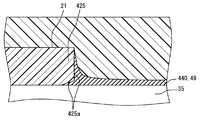
上記実施形態では、第一壁部25の壁面は、ターミナル35と実質的に直交する方向に、当該ターミナル35から立設されていた。しかし、第一壁部25の壁面がターミナル35に対してなす角度は、適宜変更されてよい。例えば、図11に示すように、第一壁部425の壁面425aがターミナルに対してなす角度は、鋭角であってもよい。第一壁部425の壁面425aが鋭角的に形成されることにより、プライマー49は、第一壁部425及びターミナル35の隙間に入り込み易くなる。こうして、塗布工程にて塗布されるプライマー49の量が増加することにより、インナーケース21内への燃料の浸入を防ぐシール膜440の機能は、さらに向上可能となる。In the above embodiment, the wall surface of the
一方で、図12に示すように、第一壁部525の壁面525aがターミナル35に対してなす角度は、鈍角であってもよい。第一壁部525の壁面525aが鈍角的に形成されることにより、塗布工程において、第一壁部525及びターミナル35の近傍にプライマー49を塗布する作業の作業性は、容易となり得る。 On the other hand, as shown in FIG. 12, the angle formed by the
上記実施形態において、ターミナル35の横断面は、矩形形状に形成されていた。しかし、ターミナルの形状は、適宜変更されてよい。例えば、ターミナルは、断面楕円形状であってもよい。さらに、ターミナル横断面は、三角形又は五角形以上の多角形状であってもよい。こうしたターミナルにおける稜線39は、横断面の輪郭形状が他の部分と比較して急激に変化している箇所とする。即ち、横断面が楕円状のターミナルであれば、稜線は、長軸方向の両端部に沿って形成される。また、横断面が多角形状のターミナルであれば、稜線は、角部分に沿って形成される。 In the said embodiment, the cross section of the terminal 35 was formed in the rectangular shape. However, the shape of the terminal may be changed as appropriate. For example, the terminal may have an elliptical cross section. Furthermore, the terminal cross section may be a triangular shape or a polygonal shape such as a pentagon or more. The
上記実施形態において、各ターミナル35に装着された堰壁体27は、互いに離間していた。しかし、第二シール膜近傍における燃料の滞留が低減可能であれば、互いに隣接する堰壁体は、一体的に形成されていてもよい。 In the above embodiment, the
上記第一実施形態において、第一シール膜40における主膜部分41a及び補助膜部分41bは、連続的に形成されていた。しかし、主膜部分及び補助膜部分は、互いに分離されていてもよい。但し、シール膜の端部が金属製のターミナル上に位置する場合、シール膜の剥離が生じ易くなる。故に、主膜部分及び補助膜部分は、連続的に形成されることが望ましい。 In the first embodiment, the
上記実施形態では、インナーケース成形工程にて、ターミナル35をインナーケース21内に埋設させることにより、第一壁部25から突出する突出部36が形成されていた。しかし、突出部は、インナーケースの成形後に当該ケースにターミナルを組み付けることにより、形成されていてもよい。 In the above embodiment, the protruding
上記実施形態において、各シール膜40,45は、ヒドリンゴムによって形成されていた。しかし、シール膜の材料は、ヒドリンゴムに限定されない。ヒドリンゴム以外のゴム材料、さらにエポキシ樹脂等が、シール膜の材料として採用可能である。さらに、シール膜を形成する工程も、上記実施形態の焼付工程に限定されない。 In the above embodiment, each of the sealing
上記実施形態では、プライマー49内の気泡を外表面に析出させることにより、アウターケース接触面42,46に、微小な凹凸49aが形成されていた。こうした凹凸49aは、クレータ状の凹みであってもよく、又は棘状の突起であってもよい。さらに、アウターケース接触面に凹凸を形成する方法は、上記の方法に限定されない。 In the embodiment described above,
上記実施形態では、インナーケース21の堰壁体27が、ターミナル35に設けられていた。しかし、ターミナルが、厚さ方向TDに突出する凸状部又は厚さ方向TDに窪む凹状部を、堰壁体27に相当する位置に形成していてもよい。こうした凸状部及び凹状部は、被覆部によって被覆されることにより、インナーケース本体近傍への燃料の浸入を妨げる機能を発揮できる。 In the above embodiment, the
上記実施形態では、ハウジング20の材料としてPPS樹脂を例に説明した。しかし、ハウジング20の材料は、PPS樹脂に限定されるものではなく、他の樹脂材料であってもよい。また、ターミナル35とリード線72との接続は、溶接によるものでなくてもよい。 In the above embodiment, the PPS resin has been described as an example of the material of the
以上、本発明を燃料の残量を検出する車両用の液面検出装置100に適用した例に基づいて説明した。しかし、本発明の適用対象は、こうした液面検出装置に限る必要はなく、車両に搭載される他の液体、例えばブレーキフルード、エンジン冷却水、エンジンオイル等の容器内の液面検出装置であってもよい。さらに、車両用に限らず、各種民生用機器、各種輸送機械が備える液体容器内に設けられる液面検出装置に、本発明は適用可能である。 The present invention has been described based on the example in which the present invention is applied to the vehicle
PD 突出方向、20,220 ハウジング(固定体)、21,221 インナーケース、22 インナーケース本体(ケース本体部分)、25,425,525 第一壁部(壁部)、27 堰壁体(凸体部分)、28 第二壁部(壁部,端面)、31 アウターケース、33 被覆部、35 ターミナル、36 突出部、36c 側面、39 稜線、40,440 第一シール膜(壁部側シール膜)、240,340 シール膜(壁部側シール膜)、42,46 アウターケース接触面(接触表面)、45 第二シール膜(突出側シール膜)、49a 凹凸、50 マグネットホルダ(回転体)、70 ホールIC(検出素子)、90 燃料タンク(容器)、91 液面、100 液面検出装置PD protruding direction, 20, 220 Housing (fixed body), 21, 221 Inner case, 22 Inner case body (case body part), 25, 425, 525 First wall part (wall part), 27 Weir wall body (convex body) Part), 28 second wall part (wall part, end face), 31 outer case, 33 covering part, 35 terminal, 36 projecting part, 36c side face, 39 ridgeline, 40,440 first seal film (wall part side seal film) , 240, 340 Seal film (wall side seal film), 42, 46 Outer case contact surface (contact surface), 45 Second seal film (projection side seal film), 49a Concavity and convexity, 50 Magnet holder (rotary body), 70 Hall IC (detection element), 90 fuel tank (container), 91 liquid level, 100 liquid level detection device
Claims (7)
Translated fromJapanese壁部(25,28)を有するインナーケース(21,221)と、
前記壁部を貫通して前記インナーケースの外部に突出する突出部(36)を有するターミナル(35)と、
前記壁部及び前記突出部を被覆する被覆部(33)と、
前記被覆部内にて前記突出部の側面(36c)と前記壁部とを繋ぐように形成され、前記ターミナルの稜線(39)上の膜厚が、前記壁部に近接するに従って増加する壁部側シール膜(40,240,340)と、を備えることを特徴とする液面検出装置。A liquid level detection device for detecting the height of the liquid level (91) of the liquid,
An inner case (21, 221) having wall portions (25, 28);
A terminal (35) having a protrusion (36) that penetrates the wall and protrudes to the outside of the inner case;
A covering portion (33) for covering the wall portion and the protruding portion;
The wall portion side formed so as to connect the side surface (36c) of the protruding portion and the wall portion within the covering portion, and the film thickness on the ridge line (39) of the terminal increases as the wall portion approaches. And a sealing film (40, 240, 340).
前記突出部の突出方向(PD)に前記壁部から離間して位置し、前記突出方向と交差する方向に前記突出部から立設される凸体部分(27)と、
前記被覆部内にて前記突出部の側面(36c)と前記凸体部分の端面(28)とを繋ぐように形成され、前記ターミナルの前記稜線上の膜厚が、前記凸体部分に近接するに従って増加する突出端側シール膜(45)と、を備えることを特徴とする請求項1〜3のいずれか一項に記載の液面検出装置。The liquid level detection device is:
A projecting portion (27) that is positioned away from the wall portion in the projecting direction (PD) of the projecting portion and is erected from the projecting portion in a direction intersecting the projecting direction;
As the side surface (36c) of the protruding portion and the end surface (28) of the convex portion are connected in the covering portion, the film thickness on the ridge line of the terminal is closer to the convex portion. The liquid level detection device according to claim 1, further comprising an increasing protruding end side sealing film (45).
複数の前記ターミナルと、
前記複数のターミナル毎に設けられる複数の前記凸体部分と、を備え、
前記複数のターミナルによる複数の前記突出部が、前記壁部から突出し、
前記複数の凸体部分のうち隣接する一対の前記凸体部分は、互いに離間していることを特徴とする請求項4に記載の液面検出装置。The liquid level detection device is:
A plurality of said terminals;
A plurality of convex portions provided for each of the plurality of terminals, and
A plurality of the protruding portions by the plurality of terminals protrude from the wall portion;
The liquid level detection device according to claim 4, wherein a pair of adjacent convex body portions among the plurality of convex body portions are separated from each other.
前記固定体に回転自在に支持され、前記液面に追従して相対回転する回転体(50)と、
前記インナーケースに収容されて前記ターミナルと接続され、前記固定体に対する前記回転体の相対角度を検出する検出素子(70)と、を備えることを特徴とする請求項1〜5のいずれか一項に記載の液面検出装置。A fixed body (20, 220) having the inner case;
A rotating body (50) that is rotatably supported by the fixed body and relatively rotates following the liquid level;
6. A detection element (70) housed in the inner case and connected to the terminal and detecting a relative angle of the rotating body with respect to the fixed body. 6. The liquid level detection apparatus described in 1.
前記ターミナルを前記壁部に貫通させることで、前記突出部を設ける突出工程(S101)と、
前記突出工程によって設けられた前記突出部から前記壁部にわたる範囲に、溶媒によって液体状態とされたシール材を塗布する塗布工程(S103)と、
前記塗布工程によって塗布された前記シール材を固体状態にすることで、前記突出部の側面(36c)と前記壁部とを繋ぐように形成され、前記ターミナルの稜線(39)上の膜厚が、前記壁部に近接するに従って増加する壁部側シール膜(40,240,340)を設ける膜形成工程(S104)と、
前記膜形成工程によって形成された前記壁部側シール膜、並びに前記壁部及び前記突出部を被覆する前記被覆部を成形する成形工程(S105)と、を含むことを特徴とする液面検出装置の製造方法。An inner case (21, 221) having wall portions (25, 28), a terminal (35) having a projecting portion (36) penetrating the wall portion and projecting to the outside of the inner case, and the wall portion And a covering portion (36) for covering the protruding portion, and a method for manufacturing a liquid level detecting device for detecting the height of the liquid level (90) of the liquid,
A projecting step (S101) of providing the projecting portion by passing the terminal through the wall;
An application step (S103) of applying a sealing material in a liquid state with a solvent in a range extending from the protruding portion provided in the protruding step to the wall portion;
By forming the sealing material applied in the application step into a solid state, the side surface (36c) of the protruding portion and the wall portion are formed to be connected, and the film thickness on the ridge line (39) of the terminal is A film-forming step (S104) for providing a wall-side sealing film (40, 240, 340) that increases as it approaches the wall;
A liquid level detecting device comprising: the wall side sealing film formed by the film forming step, and a forming step (S105) for forming the covering portion that covers the wall portion and the protruding portion. Manufacturing method.
Priority Applications (4)
| Application Number | Priority Date | Filing Date | Title |
|---|---|---|---|
| JP2012181718AJP5660088B2 (en) | 2012-08-20 | 2012-08-20 | Liquid level detection device and method of manufacturing liquid level detection device |
| PCT/JP2013/004702WO2014030308A1 (en) | 2012-08-20 | 2013-08-02 | Liquid level detection device and method for producing liquid level detection device |
| BR112015000893-3ABR112015000893B1 (en) | 2012-08-20 | 2013-08-02 | LIQUID LEVEL DETECTION DEVICE, AND, METHOD OF MANUFACTURING A LIQUID LEVEL DETECTION DEVICE |
| US14/421,935US9677925B2 (en) | 2012-08-20 | 2013-08-02 | Liquid level detection device and manufacturing method of liquid level detection device |
Applications Claiming Priority (1)
| Application Number | Priority Date | Filing Date | Title |
|---|---|---|---|
| JP2012181718AJP5660088B2 (en) | 2012-08-20 | 2012-08-20 | Liquid level detection device and method of manufacturing liquid level detection device |
Publications (2)
| Publication Number | Publication Date |
|---|---|
| JP2014038067A JP2014038067A (en) | 2014-02-27 |
| JP5660088B2true JP5660088B2 (en) | 2015-01-28 |
Family
ID=50149639
Family Applications (1)
| Application Number | Title | Priority Date | Filing Date |
|---|---|---|---|
| JP2012181718AExpired - Fee RelatedJP5660088B2 (en) | 2012-08-20 | 2012-08-20 | Liquid level detection device and method of manufacturing liquid level detection device |
Country Status (4)
| Country | Link |
|---|---|
| US (1) | US9677925B2 (en) |
| JP (1) | JP5660088B2 (en) |
| BR (1) | BR112015000893B1 (en) |
| WO (1) | WO2014030308A1 (en) |
Families Citing this family (5)
| Publication number | Priority date | Publication date | Assignee | Title |
|---|---|---|---|---|
| JP6123578B2 (en)* | 2013-08-27 | 2017-05-10 | 株式会社デンソー | Manufacturing method of liquid level detection device |
| JP6308012B2 (en) | 2014-05-16 | 2018-04-11 | 株式会社デンソー | High pressure pump control device |
| BR102016030722B1 (en)* | 2016-12-28 | 2021-07-20 | Robert Bosch Limitada | LIQUID FLUID LEVEL MEASUREMENT DEVICE IN CONFINED ENVIRONMENT |
| US10634102B2 (en)* | 2018-09-06 | 2020-04-28 | Trico Group, LLC | Fuel pump assembly |
| CN113557410A (en)* | 2019-03-20 | 2021-10-26 | 纬湃技术有限公司 | Angle detection device |
Family Cites Families (12)
| Publication number | Priority date | Publication date | Assignee | Title |
|---|---|---|---|---|
| JPH023163U (en)* | 1988-06-20 | 1990-01-10 | ||
| JPH081392B2 (en) | 1991-04-25 | 1996-01-10 | 日本電装株式会社 | Flange structure for vehicle sender and manufacturing method thereof |
| JP3365138B2 (en)* | 1995-03-09 | 2003-01-08 | 住友電装株式会社 | Connector and manufacturing method thereof |
| JP3843553B2 (en) | 1996-11-21 | 2006-11-08 | 株式会社デンソー | Connector device |
| JP3724747B2 (en)* | 2003-02-20 | 2005-12-07 | 矢崎総業株式会社 | Non-contact level sensor |
| JP4138527B2 (en)* | 2003-02-20 | 2008-08-27 | 矢崎総業株式会社 | Manufacturing method of non-contact type liquid level sensor |
| JP2004347519A (en)* | 2003-05-23 | 2004-12-09 | Hitachi Unisia Automotive Ltd | Fuel gauge |
| JP4089522B2 (en)* | 2003-06-19 | 2008-05-28 | 株式会社デンソー | Liquid level detector |
| US7377163B2 (en) | 2003-06-19 | 2008-05-27 | Denso Corporation | Liquid level detector |
| JP4125262B2 (en)* | 2004-05-07 | 2008-07-30 | 矢崎総業株式会社 | Non-contact level sensor |
| CN101683757A (en)* | 2008-09-25 | 2010-03-31 | 比亚迪股份有限公司 | Forming method and product thereof |
| JP5209038B2 (en)* | 2010-12-08 | 2013-06-12 | 日立オートモティブシステムズ株式会社 | Connector and manufacturing method thereof |
- 2012
- 2012-08-20JPJP2012181718Apatent/JP5660088B2/ennot_activeExpired - Fee Related
- 2013
- 2013-08-02BRBR112015000893-3Apatent/BR112015000893B1/ennot_activeIP Right Cessation
- 2013-08-02WOPCT/JP2013/004702patent/WO2014030308A1/enactiveApplication Filing
- 2013-08-02USUS14/421,935patent/US9677925B2/enactiveActive
Also Published As
| Publication number | Publication date |
|---|---|
| US20150192453A1 (en) | 2015-07-09 |
| JP2014038067A (en) | 2014-02-27 |
| BR112015000893A2 (en) | 2017-06-27 |
| BR112015000893B1 (en) | 2020-09-24 |
| US9677925B2 (en) | 2017-06-13 |
| WO2014030308A1 (en) | 2014-02-27 |
Similar Documents
| Publication | Publication Date | Title |
|---|---|---|
| JP5660088B2 (en) | Liquid level detection device and method of manufacturing liquid level detection device | |
| CN111034379B (en) | sealing structure | |
| JP4089522B2 (en) | Liquid level detector | |
| JP2011075413A (en) | Rotation angle detection device | |
| JP5494091B2 (en) | Manufacturing method of liquid level detection device | |
| WO2015029343A1 (en) | Method for manufacturing liquid-surface detection device, and liquid-surface detection device | |
| JP2019522190A (en) | Sensor device | |
| JP5682655B2 (en) | Liquid level detector | |
| CN105526956B (en) | Sensor arrangement and method for producing a sensor arrangement | |
| JP6634201B2 (en) | Liquid level sensor | |
| JP4743022B2 (en) | Coil device | |
| JP2010016979A (en) | Motor | |
| JP2011205002A (en) | Electronic controller | |
| JP5724974B2 (en) | Lead-acid battery, lead-acid battery terminal sealing part cover member, lead-acid battery terminal sealing method | |
| JP2014081271A (en) | Pressure sensor | |
| JP6477067B2 (en) | Liquid level detector | |
| JP6575798B2 (en) | Moving object detection device | |
| JP5494084B2 (en) | Manufacturing method of liquid level detection device | |
| JP6107462B2 (en) | Liquid level detector | |
| JP4830479B2 (en) | Metallized film capacitors | |
| JP4983653B2 (en) | Electronic circuit equipment | |
| JP6561652B2 (en) | Moving object detection device | |
| JP2001356038A (en) | Waterproof case and electronic water meter | |
| JP2014096323A (en) | Manufacturing method of terminal | |
| JP2017195093A (en) | Electricity storage element |
Legal Events
| Date | Code | Title | Description |
|---|---|---|---|
| A621 | Written request for application examination | Free format text:JAPANESE INTERMEDIATE CODE: A621 Effective date:20140522 | |
| A131 | Notification of reasons for refusal | Free format text:JAPANESE INTERMEDIATE CODE: A131 Effective date:20140826 | |
| A521 | Request for written amendment filed | Free format text:JAPANESE INTERMEDIATE CODE: A523 Effective date:20141010 | |
| TRDD | Decision of grant or rejection written | ||
| A01 | Written decision to grant a patent or to grant a registration (utility model) | Free format text:JAPANESE INTERMEDIATE CODE: A01 Effective date:20141104 | |
| A61 | First payment of annual fees (during grant procedure) | Free format text:JAPANESE INTERMEDIATE CODE: A61 Effective date:20141117 | |
| R151 | Written notification of patent or utility model registration | Ref document number:5660088 Country of ref document:JP Free format text:JAPANESE INTERMEDIATE CODE: R151 | |
| R250 | Receipt of annual fees | Free format text:JAPANESE INTERMEDIATE CODE: R250 | |
| R250 | Receipt of annual fees | Free format text:JAPANESE INTERMEDIATE CODE: R250 | |
| R250 | Receipt of annual fees | Free format text:JAPANESE INTERMEDIATE CODE: R250 | |
| R250 | Receipt of annual fees | Free format text:JAPANESE INTERMEDIATE CODE: R250 | |
| R250 | Receipt of annual fees | Free format text:JAPANESE INTERMEDIATE CODE: R250 | |
| LAPS | Cancellation because of no payment of annual fees |