JP5658103B2 - Power plug lock device - Google Patents
Power plug lock deviceDownload PDFInfo
- Publication number
- JP5658103B2 JP5658103B2JP2011154135AJP2011154135AJP5658103B2JP 5658103 B2JP5658103 B2JP 5658103B2JP 2011154135 AJP2011154135 AJP 2011154135AJP 2011154135 AJP2011154135 AJP 2011154135AJP 5658103 B2JP5658103 B2JP 5658103B2
- Authority
- JP
- Japan
- Prior art keywords
- vehicle
- plug
- power supply
- inlet
- power
- Prior art date
- Legal status (The legal status is an assumption and is not a legal conclusion. Google has not performed a legal analysis and makes no representation as to the accuracy of the status listed.)
- Expired - Fee Related
Links
Images


Classifications
- H—ELECTRICITY
- H01—ELECTRIC ELEMENTS
- H01R—ELECTRICALLY-CONDUCTIVE CONNECTIONS; STRUCTURAL ASSOCIATIONS OF A PLURALITY OF MUTUALLY-INSULATED ELECTRICAL CONNECTING ELEMENTS; COUPLING DEVICES; CURRENT COLLECTORS
- H01R13/00—Details of coupling devices of the kinds covered by groups H01R12/70 or H01R24/00 - H01R33/00
- H01R13/62—Means for facilitating engagement or disengagement of coupling parts or for holding them in engagement
- H01R13/639—Additional means for holding or locking coupling parts together, after engagement, e.g. separate keylock, retainer strap
- H01R13/6397—Additional means for holding or locking coupling parts together, after engagement, e.g. separate keylock, retainer strap with means for preventing unauthorised use
- B—PERFORMING OPERATIONS; TRANSPORTING
- B60—VEHICLES IN GENERAL
- B60L—PROPULSION OF ELECTRICALLY-PROPELLED VEHICLES; SUPPLYING ELECTRIC POWER FOR AUXILIARY EQUIPMENT OF ELECTRICALLY-PROPELLED VEHICLES; ELECTRODYNAMIC BRAKE SYSTEMS FOR VEHICLES IN GENERAL; MAGNETIC SUSPENSION OR LEVITATION FOR VEHICLES; MONITORING OPERATING VARIABLES OF ELECTRICALLY-PROPELLED VEHICLES; ELECTRIC SAFETY DEVICES FOR ELECTRICALLY-PROPELLED VEHICLES
- B60L50/00—Electric propulsion with power supplied within the vehicle
- B60L50/10—Electric propulsion with power supplied within the vehicle using propulsion power supplied by engine-driven generators, e.g. generators driven by combustion engines
- B60L50/16—Electric propulsion with power supplied within the vehicle using propulsion power supplied by engine-driven generators, e.g. generators driven by combustion engines with provision for separate direct mechanical propulsion
- B—PERFORMING OPERATIONS; TRANSPORTING
- B60—VEHICLES IN GENERAL
- B60L—PROPULSION OF ELECTRICALLY-PROPELLED VEHICLES; SUPPLYING ELECTRIC POWER FOR AUXILIARY EQUIPMENT OF ELECTRICALLY-PROPELLED VEHICLES; ELECTRODYNAMIC BRAKE SYSTEMS FOR VEHICLES IN GENERAL; MAGNETIC SUSPENSION OR LEVITATION FOR VEHICLES; MONITORING OPERATING VARIABLES OF ELECTRICALLY-PROPELLED VEHICLES; ELECTRIC SAFETY DEVICES FOR ELECTRICALLY-PROPELLED VEHICLES
- B60L53/00—Methods of charging batteries, specially adapted for electric vehicles; Charging stations or on-board charging equipment therefor; Exchange of energy storage elements in electric vehicles
- B60L53/10—Methods of charging batteries, specially adapted for electric vehicles; Charging stations or on-board charging equipment therefor; Exchange of energy storage elements in electric vehicles characterised by the energy transfer between the charging station and the vehicle
- B60L53/14—Conductive energy transfer
- B60L53/16—Connectors, e.g. plugs or sockets, specially adapted for charging electric vehicles
- B—PERFORMING OPERATIONS; TRANSPORTING
- B60—VEHICLES IN GENERAL
- B60L—PROPULSION OF ELECTRICALLY-PROPELLED VEHICLES; SUPPLYING ELECTRIC POWER FOR AUXILIARY EQUIPMENT OF ELECTRICALLY-PROPELLED VEHICLES; ELECTRODYNAMIC BRAKE SYSTEMS FOR VEHICLES IN GENERAL; MAGNETIC SUSPENSION OR LEVITATION FOR VEHICLES; MONITORING OPERATING VARIABLES OF ELECTRICALLY-PROPELLED VEHICLES; ELECTRIC SAFETY DEVICES FOR ELECTRICALLY-PROPELLED VEHICLES
- B60L53/00—Methods of charging batteries, specially adapted for electric vehicles; Charging stations or on-board charging equipment therefor; Exchange of energy storage elements in electric vehicles
- B60L53/60—Monitoring or controlling charging stations
- B60L53/65—Monitoring or controlling charging stations involving identification of vehicles or their battery types
- B—PERFORMING OPERATIONS; TRANSPORTING
- B60—VEHICLES IN GENERAL
- B60L—PROPULSION OF ELECTRICALLY-PROPELLED VEHICLES; SUPPLYING ELECTRIC POWER FOR AUXILIARY EQUIPMENT OF ELECTRICALLY-PROPELLED VEHICLES; ELECTRODYNAMIC BRAKE SYSTEMS FOR VEHICLES IN GENERAL; MAGNETIC SUSPENSION OR LEVITATION FOR VEHICLES; MONITORING OPERATING VARIABLES OF ELECTRICALLY-PROPELLED VEHICLES; ELECTRIC SAFETY DEVICES FOR ELECTRICALLY-PROPELLED VEHICLES
- B60L2210/00—Converter types
- B60L2210/30—AC to DC converters
- B—PERFORMING OPERATIONS; TRANSPORTING
- B60—VEHICLES IN GENERAL
- B60L—PROPULSION OF ELECTRICALLY-PROPELLED VEHICLES; SUPPLYING ELECTRIC POWER FOR AUXILIARY EQUIPMENT OF ELECTRICALLY-PROPELLED VEHICLES; ELECTRODYNAMIC BRAKE SYSTEMS FOR VEHICLES IN GENERAL; MAGNETIC SUSPENSION OR LEVITATION FOR VEHICLES; MONITORING OPERATING VARIABLES OF ELECTRICALLY-PROPELLED VEHICLES; ELECTRIC SAFETY DEVICES FOR ELECTRICALLY-PROPELLED VEHICLES
- B60L2240/00—Control parameters of input or output; Target parameters
- B60L2240/80—Time limits
- B—PERFORMING OPERATIONS; TRANSPORTING
- B60—VEHICLES IN GENERAL
- B60L—PROPULSION OF ELECTRICALLY-PROPELLED VEHICLES; SUPPLYING ELECTRIC POWER FOR AUXILIARY EQUIPMENT OF ELECTRICALLY-PROPELLED VEHICLES; ELECTRODYNAMIC BRAKE SYSTEMS FOR VEHICLES IN GENERAL; MAGNETIC SUSPENSION OR LEVITATION FOR VEHICLES; MONITORING OPERATING VARIABLES OF ELECTRICALLY-PROPELLED VEHICLES; ELECTRIC SAFETY DEVICES FOR ELECTRICALLY-PROPELLED VEHICLES
- B60L2250/00—Driver interactions
- B60L2250/16—Driver interactions by display
- B—PERFORMING OPERATIONS; TRANSPORTING
- B60—VEHICLES IN GENERAL
- B60L—PROPULSION OF ELECTRICALLY-PROPELLED VEHICLES; SUPPLYING ELECTRIC POWER FOR AUXILIARY EQUIPMENT OF ELECTRICALLY-PROPELLED VEHICLES; ELECTRODYNAMIC BRAKE SYSTEMS FOR VEHICLES IN GENERAL; MAGNETIC SUSPENSION OR LEVITATION FOR VEHICLES; MONITORING OPERATING VARIABLES OF ELECTRICALLY-PROPELLED VEHICLES; ELECTRIC SAFETY DEVICES FOR ELECTRICALLY-PROPELLED VEHICLES
- B60L2270/00—Problem solutions or means not otherwise provided for
- B60L2270/30—Preventing theft during charging
- B60L2270/32—Preventing theft during charging of electricity
- B—PERFORMING OPERATIONS; TRANSPORTING
- B60—VEHICLES IN GENERAL
- B60L—PROPULSION OF ELECTRICALLY-PROPELLED VEHICLES; SUPPLYING ELECTRIC POWER FOR AUXILIARY EQUIPMENT OF ELECTRICALLY-PROPELLED VEHICLES; ELECTRODYNAMIC BRAKE SYSTEMS FOR VEHICLES IN GENERAL; MAGNETIC SUSPENSION OR LEVITATION FOR VEHICLES; MONITORING OPERATING VARIABLES OF ELECTRICALLY-PROPELLED VEHICLES; ELECTRIC SAFETY DEVICES FOR ELECTRICALLY-PROPELLED VEHICLES
- B60L2270/00—Problem solutions or means not otherwise provided for
- B60L2270/30—Preventing theft during charging
- B60L2270/34—Preventing theft during charging of parts
- Y—GENERAL TAGGING OF NEW TECHNOLOGICAL DEVELOPMENTS; GENERAL TAGGING OF CROSS-SECTIONAL TECHNOLOGIES SPANNING OVER SEVERAL SECTIONS OF THE IPC; TECHNICAL SUBJECTS COVERED BY FORMER USPC CROSS-REFERENCE ART COLLECTIONS [XRACs] AND DIGESTS
- Y02—TECHNOLOGIES OR APPLICATIONS FOR MITIGATION OR ADAPTATION AGAINST CLIMATE CHANGE
- Y02T—CLIMATE CHANGE MITIGATION TECHNOLOGIES RELATED TO TRANSPORTATION
- Y02T10/00—Road transport of goods or passengers
- Y02T10/60—Other road transportation technologies with climate change mitigation effect
- Y02T10/70—Energy storage systems for electromobility, e.g. batteries
- Y—GENERAL TAGGING OF NEW TECHNOLOGICAL DEVELOPMENTS; GENERAL TAGGING OF CROSS-SECTIONAL TECHNOLOGIES SPANNING OVER SEVERAL SECTIONS OF THE IPC; TECHNICAL SUBJECTS COVERED BY FORMER USPC CROSS-REFERENCE ART COLLECTIONS [XRACs] AND DIGESTS
- Y02—TECHNOLOGIES OR APPLICATIONS FOR MITIGATION OR ADAPTATION AGAINST CLIMATE CHANGE
- Y02T—CLIMATE CHANGE MITIGATION TECHNOLOGIES RELATED TO TRANSPORTATION
- Y02T10/00—Road transport of goods or passengers
- Y02T10/60—Other road transportation technologies with climate change mitigation effect
- Y02T10/7072—Electromobility specific charging systems or methods for batteries, ultracapacitors, supercapacitors or double-layer capacitors
- Y—GENERAL TAGGING OF NEW TECHNOLOGICAL DEVELOPMENTS; GENERAL TAGGING OF CROSS-SECTIONAL TECHNOLOGIES SPANNING OVER SEVERAL SECTIONS OF THE IPC; TECHNICAL SUBJECTS COVERED BY FORMER USPC CROSS-REFERENCE ART COLLECTIONS [XRACs] AND DIGESTS
- Y02—TECHNOLOGIES OR APPLICATIONS FOR MITIGATION OR ADAPTATION AGAINST CLIMATE CHANGE
- Y02T—CLIMATE CHANGE MITIGATION TECHNOLOGIES RELATED TO TRANSPORTATION
- Y02T10/00—Road transport of goods or passengers
- Y02T10/60—Other road transportation technologies with climate change mitigation effect
- Y02T10/72—Electric energy management in electromobility
- Y—GENERAL TAGGING OF NEW TECHNOLOGICAL DEVELOPMENTS; GENERAL TAGGING OF CROSS-SECTIONAL TECHNOLOGIES SPANNING OVER SEVERAL SECTIONS OF THE IPC; TECHNICAL SUBJECTS COVERED BY FORMER USPC CROSS-REFERENCE ART COLLECTIONS [XRACs] AND DIGESTS
- Y02—TECHNOLOGIES OR APPLICATIONS FOR MITIGATION OR ADAPTATION AGAINST CLIMATE CHANGE
- Y02T—CLIMATE CHANGE MITIGATION TECHNOLOGIES RELATED TO TRANSPORTATION
- Y02T90/00—Enabling technologies or technologies with a potential or indirect contribution to GHG emissions mitigation
- Y02T90/10—Technologies relating to charging of electric vehicles
- Y02T90/12—Electric charging stations
- Y—GENERAL TAGGING OF NEW TECHNOLOGICAL DEVELOPMENTS; GENERAL TAGGING OF CROSS-SECTIONAL TECHNOLOGIES SPANNING OVER SEVERAL SECTIONS OF THE IPC; TECHNICAL SUBJECTS COVERED BY FORMER USPC CROSS-REFERENCE ART COLLECTIONS [XRACs] AND DIGESTS
- Y02—TECHNOLOGIES OR APPLICATIONS FOR MITIGATION OR ADAPTATION AGAINST CLIMATE CHANGE
- Y02T—CLIMATE CHANGE MITIGATION TECHNOLOGIES RELATED TO TRANSPORTATION
- Y02T90/00—Enabling technologies or technologies with a potential or indirect contribution to GHG emissions mitigation
- Y02T90/10—Technologies relating to charging of electric vehicles
- Y02T90/14—Plug-in electric vehicles
- Y—GENERAL TAGGING OF NEW TECHNOLOGICAL DEVELOPMENTS; GENERAL TAGGING OF CROSS-SECTIONAL TECHNOLOGIES SPANNING OVER SEVERAL SECTIONS OF THE IPC; TECHNICAL SUBJECTS COVERED BY FORMER USPC CROSS-REFERENCE ART COLLECTIONS [XRACs] AND DIGESTS
- Y02—TECHNOLOGIES OR APPLICATIONS FOR MITIGATION OR ADAPTATION AGAINST CLIMATE CHANGE
- Y02T—CLIMATE CHANGE MITIGATION TECHNOLOGIES RELATED TO TRANSPORTATION
- Y02T90/00—Enabling technologies or technologies with a potential or indirect contribution to GHG emissions mitigation
- Y02T90/10—Technologies relating to charging of electric vehicles
- Y02T90/16—Information or communication technologies improving the operation of electric vehicles
- Y02T90/167—Systems integrating technologies related to power network operation and communication or information technologies for supporting the interoperability of electric or hybrid vehicles, i.e. smartgrids as interface for battery charging of electric vehicles [EV] or hybrid vehicles [HEV]
- Y—GENERAL TAGGING OF NEW TECHNOLOGICAL DEVELOPMENTS; GENERAL TAGGING OF CROSS-SECTIONAL TECHNOLOGIES SPANNING OVER SEVERAL SECTIONS OF THE IPC; TECHNICAL SUBJECTS COVERED BY FORMER USPC CROSS-REFERENCE ART COLLECTIONS [XRACs] AND DIGESTS
- Y04—INFORMATION OR COMMUNICATION TECHNOLOGIES HAVING AN IMPACT ON OTHER TECHNOLOGY AREAS
- Y04S—SYSTEMS INTEGRATING TECHNOLOGIES RELATED TO POWER NETWORK OPERATION, COMMUNICATION OR INFORMATION TECHNOLOGIES FOR IMPROVING THE ELECTRICAL POWER GENERATION, TRANSMISSION, DISTRIBUTION, MANAGEMENT OR USAGE, i.e. SMART GRIDS
- Y04S30/00—Systems supporting specific end-user applications in the sector of transportation
- Y04S30/10—Systems supporting the interoperability of electric or hybrid vehicles
- Y04S30/14—Details associated with the interoperability, e.g. vehicle recognition, authentication, identification or billing
Landscapes
- Engineering & Computer Science (AREA)
- Power Engineering (AREA)
- Transportation (AREA)
- Mechanical Engineering (AREA)
- Computer Security & Cryptography (AREA)
- Lock And Its Accessories (AREA)
- Electric Propulsion And Braking For Vehicles (AREA)
- Details Of Connecting Devices For Male And Female Coupling (AREA)
- Charge And Discharge Circuits For Batteries Or The Like (AREA)
- Hybrid Electric Vehicles (AREA)
- Arrangement Or Mounting Of Propulsion Units For Vehicles (AREA)
Description
Translated fromJapanese本発明は、受電コネクタに接続されてバッテリに充電を行う給電プラグのロック装置に関する。 The present invention relates to a power supply plug locking device that is connected to a power receiving connector and charges a battery.
近年、車両からの排出ガスを少なく抑えることを目的として、各車両メーカでは、モータを駆動源とする電気自動車(ハイブリッド車も含む)の開発気運が非常に高くなってきている。このような電気自動車では、車両の動力源を駆動するためのバッテリの電力残量が少なくなる度に、例えば家庭や電気スタンド等においてバッテリに充電を行う必要がある。このことから、電気自動車にはユーザにも簡単に扱える様々な充電システムが設けられることになる。このようなシステムとしては、例えば特許文献1に示されるものが知られている。このシステムでは、例えば家庭の商用電源に繋がる給電プラグを接続可能としたインレット(受電コネクタ)を車両に設け、帰宅したときなどに駐車車両のインレットに給電プラグを接続し、商用電源を車両に送り込むことによって車両のバッテリに充電を行う。給電プラグには係止爪が、インレットには係合部がそれぞれ形成されており、両者が係合することにより、給電プラグとインレットとの接続が維持される。給電プラグに設けられる操作部の操作に連動して係止爪が変位することにより、係合部との係合状態が解除される。これにより、給電プラグをインレットから取り外し可能となる。 In recent years, for the purpose of suppressing the exhaust gas from vehicles to a small extent, each vehicle manufacturer has become very active in developing electric vehicles (including hybrid vehicles) using a motor as a drive source. In such an electric vehicle, it is necessary to charge the battery at, for example, a home or a desk lamp each time the remaining amount of power of the battery for driving the power source of the vehicle decreases. For this reason, the electric vehicle is provided with various charging systems that can be easily handled by the user. As such a system, for example, a system disclosed in Patent Document 1 is known. In this system, for example, an inlet (power receiving connector) that enables connection of a power supply plug that connects to a commercial power supply at home is provided in the vehicle, and the power supply plug is connected to the inlet of the parked vehicle when returning home and the commercial power supply is sent to the vehicle. Thus, the vehicle battery is charged. An engaging claw is formed on the power plug, and an engaging portion is formed on the inlet. By engaging both, the connection between the power plug and the inlet is maintained. The engaging claw is displaced in conjunction with the operation of the operating portion provided on the power supply plug, so that the engaged state with the engaging portion is released. Thereby, the power supply plug can be removed from the inlet.
ところで、バッテリの充電には、ガソリン車のガソリン補給に比べて比較的長い時間を要する。このことから給電プラグをインレットに接続した状態で車両を長時間放置するケースが多くなる。このため、例えば、給電中の車両から不正に給電プラグを取り外して別の車両のインレットに装着して盗電されたり、給電プラグ自体が盗まれたりすることも想定される。そこで、バッテリの充電中における係止爪の変位を規制するために、給電プラグのロック装置が考案されている。このようなロック装置の例として、モータにより駆動されるロックバーを備えたものがある。このロックバーは、給電プラグの係止爪がインレットの係合部に係合した状態で、ロック位置に位置して係止爪の動きを固定する。このロックバーによるロック状態では、給電プラグをインレットから引き抜くことができなくなる。給電プラグをインレットから取り外すには、ロックバーをアンロック位置に位置させて給電プラグの係止爪の動きを許容する。なお、こうしたロック装置には、インレットと給電プラグとの接続を検出するセンサとアンロックスイッチが設けられている。センサが接続を検出したとき、ロックバーは、アンロック位置からロック位置へ変位する。アンロックスイッチが操作されたとき、ロックバーはロック位置からアンロック位置へ変位する。 By the way, charging the battery requires a relatively long time compared to the gasoline supply of a gasoline car. For this reason, there are many cases where the vehicle is left for a long time with the power supply plug connected to the inlet. For this reason, for example, it is also assumed that the power supply plug is illegally removed from the vehicle being supplied and attached to the inlet of another vehicle to be stolen, or the power supply plug itself is stolen. Therefore, in order to regulate the displacement of the locking claws during charging of the battery, a power supply plug locking device has been devised. As an example of such a locking device, there is one having a lock bar driven by a motor. The lock bar is located at the lock position and fixes the movement of the locking claw in a state where the locking claw of the power supply plug is engaged with the engaging portion of the inlet. In the locked state by the lock bar, the power supply plug cannot be pulled out from the inlet. In order to remove the power supply plug from the inlet, the lock bar is positioned at the unlock position to allow the movement of the engaging claw of the power supply plug. Such a locking device is provided with a sensor for detecting the connection between the inlet and the power supply plug and an unlock switch. When the sensor detects a connection, the lock bar is displaced from the unlock position to the lock position. When the unlock switch is operated, the lock bar is displaced from the lock position to the unlock position.
近年の車両には、例えば、特許文献2に示すように、ユーザの携帯する電子キーとの間で無線通信を行い、この無線通信が成立する場合にのみ車両ドアの施解錠やエンジンの始動を許可するスマートシステムが搭載されている。車両は、LF帯の無線信号を間欠的に送信することにより、車両の周辺に送信エリアを形成する。電子キーは、通信エリアに入ってLF帯の無線信号を受信すると、UHF帯の無線信号を送信する。車両は、受信したUHF帯の無線信号の妥当性が確認されるとき、ドアの解錠などを許可する。 In recent vehicles, for example, as shown in Patent Document 2, wireless communication is performed with an electronic key carried by the user, and only when the wireless communication is established, locking and unlocking of the vehicle door and starting of the engine are performed. A smart system to allow is installed. The vehicle intermittently transmits LF band radio signals to form a transmission area around the vehicle. When the electronic key enters the communication area and receives a radio signal in the LF band, the electronic key transmits a radio signal in the UHF band. When the validity of the received UHF band radio signal is confirmed, the vehicle permits the unlocking of the door.
近年、防犯の観点から、このスマートシステムを利用した給電プラグのロック装置の開発が行われている。このようなロック装置では、例えば、インレットの近傍にLF帯の無線信号を発信するアンテナを設ける。そして、このアンテナからの無線信号をトリガとして車両と電子キーとの間で無線通信が成立したときに、ロック装置は、給電プラグの取り外しを許可する。このように構成することにより、給電プラグの不正取り外しをさらに抑制することができる。 In recent years, from the viewpoint of crime prevention, a power supply plug locking device using this smart system has been developed. In such a locking device, for example, an antenna for transmitting an LF band radio signal is provided in the vicinity of the inlet. Then, when wireless communication is established between the vehicle and the electronic key using the wireless signal from the antenna as a trigger, the lock device permits removal of the power supply plug. With this configuration, unauthorized removal of the power supply plug can be further suppressed.
しかしながら、先の通信エリアを形成する無線信号と、インレットのアンテナからの無線信号とが重なることが懸念される。LF帯の無線信号は、重なり合う場合、互いに干渉して打ち消し合うことがわかっている。この干渉が起きた場合、電子キーは、LF帯の無線信号を受信できるエリアに侵入しても、その無線信号を受信できないおそれがある。電子キーが無線信号を受信できない場合、電子キーと車両との間の無線通信が成立しないので、給電プラグのロック装置は、給電プラグの取り外しを許可しない。 However, there is a concern that the radio signal forming the previous communication area and the radio signal from the inlet antenna overlap. LF band radio signals are known to interfere and cancel each other if they overlap. When this interference occurs, the electronic key may not be able to receive the radio signal even if it enters an area where the radio signal of the LF band can be received. If the electronic key cannot receive a wireless signal, wireless communication between the electronic key and the vehicle is not established, and therefore the power plug plug locking device does not permit removal of the power plug.
本発明は、こうした実状に鑑みてなされたものであり、その目的は、無線信号の信頼性を確保することにより、動作の信頼性を確保することができる給電プラグのロック装置を提供することにある。 The present invention has been made in view of such circumstances, and an object of the present invention is to provide a power supply plug locking device that can ensure the reliability of operation by ensuring the reliability of a radio signal. is there.
上記課題を解決するために、請求項1に記載の発明は、電子キーとの間で相互に行われる無線信号の授受を通じて、ドアの解錠を実行又は許可する認証機能を備えた車両に搭載され、車両のインレットに接続される給電プラグの許可のない取り外しを規制する一方で、前記認証機能を通じて、前記給電プラグの前記インレットからの取り外しの許可を行う制御装置を備える給電プラグのロック装置において、前記車両は、前記電子キーに対して応答を要求する無線信号を発信するアンテナを複数個備え、そのうちの一つは、前記給電プラグの取り外しの許可に係る応答を要求する無線信号を発信するもの、他のアンテナは、ドアの解錠の実行又は許可に係る応答を要求する無線信号を発信するものとし、前記制御装置は、駐車中は通常、一のアンテナを通じた前記給電プラグの取り外しに係る無線信号の送信を停止した状態に維持しつつ、前記他のアンテナを通じてドアの解錠に係る無線信号を送信する一方で、前記給電プラグの取り外しにかかる無線信号を送信する際には、ドアの解錠に係る無線信号の発信を停止することを要旨とする。 In order to solve the above-mentioned problem, the invention according to claim 1 is mounted on a vehicle having an authentication function for executing or permitting unlocking of a door through transmission and reception of a wireless signal mutually performed with an electronic key. A power plug locking device comprising a control device that permits removal of the power plug from the inlet through the authentication function while restricting unauthorized removal of the power plug connected to the vehicle inlet The vehicle includes a plurality of antennas that transmit wireless signals that request a response to the electronic key, one of which transmits a wireless signal that requests a response relating to permission to remove the power plug. The other antenna shall transmit a radio signal requesting a response relating to execution or permission of unlocking the door. A wireless signal related to the removal of the power supply plug is transmitted while the wireless signal related to the unlocking of the door is transmitted through the other antenna while the transmission of the wireless signal related to the removal of the power supply plug through the antenna is stopped. When transmitting a signal, the gist is to stop transmission of a radio signal related to unlocking the door.
同構成によれば、給電プラグのインレットからの取り外しの許可するために発信される無線信号は、ドアの解錠を実行又は許可するために発信される他の発信機からの無線信号と同じタイミングで発信されることがない。従って、給電プラグの取り外しに係る無線信号とドアの解錠に係る無線信号とが干渉し合うこともない。このため、干渉に起因して電子キーと車両との間の無線通信が阻害されることもない。これにより、電子キーと車両との間の無線通信、ひいては給電プラグのロック装置の動作の信頼性を確保することができる。 According to this configuration, the wireless signal transmitted to permit removal of the power plug from the inlet is the same timing as the wireless signal transmitted from another transmitter that is transmitted to execute or permit the unlocking of the door. It will not be sent on. Therefore, the radio signal related to removal of the power supply plug and the radio signal related to unlocking the door do not interfere with each other. For this reason, wireless communication between the electronic key and the vehicle is not hindered due to interference. Thereby, it is possible to ensure the reliability of the wireless communication between the electronic key and the vehicle, and thus the operation of the power plug locking device.
請求項2に記載の発明は、請求項1に記載の給電プラグのロック装置において、前記車両は、前記給電プラグを前記インレットから取り外すときに操作されるスイッチを備え、前記制御装置は、前記スイッチが操作されたとき、ドアの解錠に係る無線信号の送信を停止するとともに、前記給電プラグの取り外しに係る無線信号を送信することを要旨とする。 According to a second aspect of the present invention, in the power plug locking device according to the first aspect, the vehicle includes a switch operated when the power plug is removed from the inlet, and the control device includes the switch When the is operated, the transmission of the wireless signal related to the unlocking of the door is stopped and the wireless signal related to the removal of the power supply plug is transmitted.
同構成によれば、他の発信機からの無線信号の送信が停止されて一の発信機から無線信号が発信されるのは、スイッチが操作されたときのみである。換言すれば、スイッチが操作されない限り給電プラグの取り外しに係る無線信号が送信されることはなく、他の発信機からドアの解錠に係る無線信号が発信される。このため、ドアの解錠に係る電子キーと車両との間の無線信号の授受は好適に行われる。 According to this configuration, the transmission of the radio signal from the other transmitter is stopped and the radio signal is transmitted from the one transmitter only when the switch is operated. In other words, unless the switch is operated, a wireless signal related to removal of the power supply plug is not transmitted, and a wireless signal related to unlocking the door is transmitted from another transmitter. For this reason, transmission / reception of a radio signal between the electronic key related to unlocking the door and the vehicle is preferably performed.
請求項3に記載の発明は、請求項1又は2に記載の給電プラグのロック装置において、前記制御装置は、前記給電プラグの前記インレットからの取り外しを許可したことを契機として前記給電プラグの取り外しに要すると想定される時間に基づき設定される一定期間だけ作動するタイマを備え、同タイマの作動中に前記給電プラグが前記インレットから取り外されなければ、再度前記給電プラグの前記インレットからの取り外しを規制することを要旨とする。 According to a third aspect of the present invention, in the locking device for the power plug according to the first or second aspect, the control device removes the power plug when triggered by the removal of the power plug from the inlet. Provided with a timer that operates only for a certain period set based on the time that is assumed to be required, and if the power plug is not removed from the inlet during the operation of the timer, the power plug is removed from the inlet again. The gist is to regulate.
同構成によれば、給電プラグの取り外しが許可された後、一定期間にわたって給電プラグがインレットから取り外されなかった場合、制御装置は再度給電プラグの取り外しを規制する。これにより、例えば、ユーザが離れているときに給電プラグが不正に取り外されることを抑制することができる。 According to this configuration, after the removal of the power plug is permitted, if the power plug is not removed from the inlet for a certain period, the control device again regulates the removal of the power plug. Thereby, for example, when the user is away, the power plug can be prevented from being removed illegally.
本発明では、無線信号の信頼性を確保することにより、動作の信頼性を確保することができる給電プラグのロック装置を提供することができる。 According to the present invention, it is possible to provide a power supply plug locking device capable of ensuring the reliability of operation by ensuring the reliability of a radio signal.
以下、本発明の給電プラグのロック装置をプラグインハイブリッド車に具体化した一実施形態を図面に従って説明する。
<電子キーシステム>
図1に示すように、車両1には、例えば運転者が実際に車両キーを操作しなくてもドアの施解錠を可能とする電子キーシステム70が搭載されている。電子キーシステム70は、車両1との間で相互に無線通信を行う電子キー80を備える。Hereinafter, an embodiment in which a power plug locking device of the present invention is embodied in a plug-in hybrid vehicle will be described with reference to the drawings.
<Electronic key system>
As shown in FIG. 1, the vehicle 1 is equipped with an
車両1には、電子キー80及び車両1のIDコードの照合を行う照合ECU(Electronic Control Unit)71が設けられている。照合ECU71は、車両1に固有のキーコードとしてIDコードが記憶されたメモリ71aを備えている。照合ECU71には、車外LF(Low Frequency)発信機72と、車内LF発信機73と、UHF(Ultra High Frequency)受信機74とが接続されている。車外LF発信機72のアンテナは、車両1の各ドア及び後述するインレット31に埋設されて車外にLF帯の信号を発信する。車内LF発信機73のアンテナは、車内床下等に埋設されて車内にLF帯の無線信号を発信する。UHF受信機74のアンテナは、車内に埋設されてUHF帯の無線信号を受信する。これら各アンテナは切り替え可能とされている。なお、車両1が発信するLF帯の無線信号にはウェイク信号Swkとチャレンジ信号Schとがある。ウェイク信号Swkは、電子キー80が車両1の近傍に存在することを確認するための信号であり、チャレンジ信号Schは、電子キー80にIDコードを要求する信号である。 The vehicle 1 is provided with a verification ECU (Electronic Control Unit) 71 that performs verification of the
一方、電子キー80には、通信制御部81が設けられている。通信制御部81は、電子キー80に固有のIDコードが記憶されたメモリ81aを備えている。通信制御部81には、LF帯の無線信号を受信するLF受信部82と、通信制御部81の指令に従いUHF帯の無線信号を発信するUHF発信部83とが接続されている。なお、電子キー80が発信するUHF帯の無線信号にはアック信号SacとIDコード信号Sidとがある。アック信号Sacは、ウェイク信号Swkに対して応答するための信号であり、IDコード信号Sidは、チャレンジ信号Schに対して応答するための信号で自身のIDコードが含まれる。 On the other hand, the
照合ECU71は、車外LF発信機72からLF帯のウェイク信号Swkを間欠的に発信させることにより、車両1の周辺に車外通信エリアを形成する。このとき照合ECU71は、各ドアのアンテナのみを動作させて、インレット31のアンテナは停止した状態に維持する。電子キー80は、車外通信エリアに進入すると、LF受信部82を介してウェイク信号Swkを受信する。通信制御部81は、LF受信部82を介してウェイク信号Swkを受信するとこれに対する応答として、UHF帯のアック信号Sacを、UHF発信部83を介して発信する。 The verification ECU 71 forms an out-of-vehicle communication area around the vehicle 1 by intermittently transmitting the LF band wake signal Swk from the out-of-
照合ECU71は、UHF受信機74を介してアック信号Sacを受信すると、車外LF発信機72からLF帯のチャレンジ信号Schを発信する。電子キー80の通信制御部81は、LF受信部82を介してチャレンジ信号Schを受信すると、自身のメモリ81aに登録されたIDコードを含ませたUHF帯のIDコード信号Sidを、UHF発信部83を介して発信する。照合ECU71は、UHF受信機74を介してIDコード信号Sidを受信すると、自身のメモリ71aに登録されたIDコードとIDコード信号Sidに含まれるIDコードとのID照合(車外照合)を行う。照合ECU71は、車外照合が成立した状態で、ドアハンドルに設けられる図示しない生体センサを介してユーザのドアハンドルへの接触を検出すると、同じく図示しないドアロック装置による車両ドアの解錠を実行する。 When the verification ECU 71 receives the ACK signal Sac via the
照合ECU71は、車外照合が成立して車両ドアが解錠された後、ドアが開けられて運転者が乗車したことを認識すると、今度は車内LF発信機73からウェイク信号Swkを発信して車内全域に車内通信エリアを形成する。電子キー80は、車内通信エリアに進入すると、先の車外照合と同様のID照合(車内照合)を行う。照合ECU71は、車内照合が成立すると、後述するハイブリッドシステム3の始動を許可する。 When the verification ECU 71 recognizes that the driver has boarded after opening the door after the vehicle verification is established and the vehicle door is unlocked, the verification ECU 71 transmits the wake signal Swk from the in-
<充電システム>
図1に示すように、車両1には、駆動輪2の駆動源としてエンジンとモータとを組み合わせて使用するハイブリッドシステム3が備えられている。ハイブリッドシステム3は、エンジンの動力のみを機械的に駆動輪2に伝えて走行するモードと、エンジンの動力で発電を行ってモータの回転を駆動輪2に伝えて走行するモードと、エンジン及びモータの双方で駆動輪2を駆動するモードと、エンジンを使用せずにモータのみで走行するモードとを有している。<Charging system>
As shown in FIG. 1, the vehicle 1 includes a
ハイブリッドシステム3には、モータに電力を供給する走行用のバッテリ4が接続されている。バッテリ4は、エンジンの動力によって発電された電力が充電されるだけでなく、車両1の外部電源91からの電力が充電可能とされている。 The
バッテリ4は、プラグイン式の充電システム90によって充電される。充電システム90は、住宅や電気スタンド等の外部電源91に接続ケーブル12を介して接続される給電プラグ10を備えている。給電プラグ10は、車両1に接続可能とされている。外部電源91からは交流電力が給電プラグ10を介して車両1に供給される。接続ケーブル12には、充電を開始する際に操作される充電スイッチ92が設けられている。給電プラグ10が車両1に接続された状態において、充電スイッチ92がオン操作又はオフ操作されると、その旨の信号が給電プラグ10を介して車両1に出力される。 The
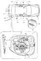
車両1には、給電プラグ10の接続先としてインレット31が取り付けられている。インレット31は、給電プラグ10を挿し込むコネクタ部品であって、本例では、図2に示すように、車両1の後部右側面に設けられている。インレット31は、車両1に対して開閉可能に設けられたフェンダーリッドにより外部環境から保護されている。 An
インレット31に給電プラグ10が挿し込まれることにより、これらは電気的に接続される。インレット31に供給される交流電力は、コンバータ6によって直流電力に変換され、この直流電力がバッテリ4に供給される。 By inserting the
車両1には、充電に関わる制御を行う充電ECU75が設けられている。充電ECU75は、図示しない車内LAN(Local Area Network)を介して照合ECU71との間で通信可能とされている。充電ECU75は、当該通信を通じて照合ECU71におけるID照合の成立結果を確認可能である。また、充電ECU75は、信号線の接続状態等に基づき給電プラグ10がインレット31に挿し込まれたことを認識可能である。 The vehicle 1 is provided with a charging
インレット31には、ロック機構41及びモジュール51が設けられている。ロック機構41は、インレット31に接続された給電プラグ10の取り外しを規制するものである。モジュール51は、充電状態を示す充電インジケータなどの各種電装部品が一体とされたものである。本例では、ロック機構41は、車両1の内部におけるインレット31の上部に、モジュール51は、インレット31の車両外側に設けられている。なお、図1に示すように、これらロック機構41及びモジュール51は、充電ECU75に電気的に接続されている。 The
ロック機構41には、給電プラグ10がインレット31に好適に挿入された状態であることを検出する挿入検出装置43が設けられている。挿入検出装置43は、充電ECU75に電気的に接続されている。充電ECU75は、挿入検出装置43を通じて、給電プラグ10とインレット31との接続状態を判断する。充電ECU75は、インレット31に給電プラグ10が接続された旨認識した場合には、ロック機構41を通じて、インレット31に接続された給電プラグ10の許可のない取り外しを規制する(ロック状態)。 The
充電ECU75は、給電プラグ10とインレット31とが接続された状態において、充電スイッチ92がオン操作された旨の信号を給電プラグ10及びインレット31を介して受けるとコンバータ6の制御を通じてバッテリ4への給電を開始する。 When the
モジュール51には、アンロックスイッチ53が設けられている。アンロックスイッチ53が操作されると、その旨の信号が充電ECU75に出力される。充電ECU75は、アンロックスイッチ53が操作されたことを認識すると、照合ECU71及び車外LF発信機72を通じて車外ID照合を行う。このとき、照合ECU71は、各ドアのアンテナの動作を停止し、インレット31のアンテナのみ動作させる。照合ECU71には、タイマ71bが設けられている。タイマ71bのカウント終了時間は、2秒に設定されている。照合ECU71は、充電ECU75から、アンロックスイッチ53が操作された旨示す信号を受信すると、タイマ71bを作動させて、このタイマ71bが作動している間だけ、車外LF発信機72から特定のエリアに向けてウェイク信号Swkを発信する。充電ECU75は、照合ECU71を通じて、アンロックスイッチ53の操作をトリガとする車外ID照合が成立した旨認識すると、ロック機構41を通じて、インレット31に接続された給電プラグ10の取り外しを許可する(アンロック状態)。このとき、充電ECU75は、コンバータ6の制御を通じて、給電プラグ10からバッテリ4への充電を停止する。なお、充電ECU75には、タイマ75bが設けられている。タイマ71bのカウント終了時間は、30秒に設定されている。タイマ75bは、ロック機構41がアンロック状態とされたことを契機として作動する。充電ECU75は、タイマ75bの作動中にインレット31から給電プラグ10が取り外されなければ、ロック機構41を再度、ロック状態に移行させる。 The
次に、車両の周辺に形成される通信エリアについて説明する。
図2に示すように、車両1には、5枚のドア8DF(Driver Front),8DR(Driver Rear),8PF(Passenger Front),8PR(Passenger Rear),8TL(Tail)が設けられている。ドア8TLは、いわゆるトランクリッドである。6つのアンテナのうち4つのアンテナDF,DR,PF,PRは、各ドア8DF,8DR,8PF,8PRのドアノブに埋設されている。アンテナTLは、ドア8TLに埋設されている。これら各アンテナDF,DR,PF,PR,TLは、図1に示すように、車外LF発信機72と接続されている。なお、通常は、1つのアンテナに対して1つの車外LF発信機を設けるが、ここでは、図面が複雑になって見にくくなることを回避するために車外LF発信機を一つにまとめている。Next, a communication area formed around the vehicle will be described.
As shown in FIG. 2, the vehicle 1 is provided with five doors 8DF (Driver Front), 8DR (Driver Rear), 8PF (Passenger Front), 8PR (Passenger Rear), and 8TL (Tail). The door 8TL is a so-called trunk lid. Of the six antennas, four antennas DF, DR, PF, and PR are embedded in the door knobs of the doors 8DF, 8DR, 8PF, and 8PR. The antenna TL is embedded in the door 8TL. Each of these antennas DF, DR, PF, PR, and TL is connected to an
図2に示すように、各アンテナDF,DR,PF,PR,TLには、車外通信エリアSdf,Sdr,Spf,Spr,Stlが設定されている。この車外通信エリアSdf,Sdr,Spf,Spr,Stlは、それぞれのアンテナDF,DR,PF,PR,TLを中心とする半径約1mとされた半球状とされている。なお、トランクリッドにも、図示しない生体センサが設けられている。生体センサは、ユーザの接触を検出してその旨示す信号を照合ECU71に送る。 As shown in FIG. 2, vehicle communication areas Sdf, Sdr, Spf, Spr, Stl are set for the antennas DF, DR, PF, PR, TL. The outside communication areas Sdf, Sdr, Spf, Spr, Stl are hemispherical with a radius of about 1 m centered on the respective antennas DF, DR, PF, PR, TL. The trunk lid is also provided with a biosensor (not shown). The biometric sensor detects a user's contact and sends a signal indicating that to the verification ECU 71.
インレット31は、ドア8DRのさらに後方に設けられている。アンテナMLは、インレット31のモジュール51に埋設されている。このアンテナMLは、先の各アンテナDF,DR,PF,PR,TLと同様に車外通信エリアSmlが設定されている。この車外通信エリアSmlは、アンテナMLを中心とする半径約1mとされた半球状とされている。図2に示すように、車外通信エリアSmlの一部は、車外通信エリアSdr,Stlと重なっている。 The
次に車外ID照合について説明する。このとき車両1は、駐車状態とする。また、給電プラグ10は、インレット31に接続されているものとする。
図3に示すように、照合ECU71は、アンテナDF,DR,PF,PR,TLから各車外通信エリアSdf,Sdr,Spf,Spr,Stlに向けてLF帯のウェイク信号Swkを間欠的に発信させる。また、各アンテナDF,DR,PF,PR,TLは、ウェイク信号Swkを同時に発信する。電子キー80は、この車外通信エリアSdf,Sdr,Spf,Spr,Stlのいずれかに進入して、ウェイク信号Swkを受信すると、これに対する応答としてアック信号Sacを発信する。Next, ID verification outside the vehicle will be described. At this time, the vehicle 1 is parked. In addition, the
As shown in FIG. 3, the verification ECU 71 intermittently transmits the wake signal Swk in the LF band from the antennas DF, DR, PF, PR, and TL to the external communication areas Sdf, Sdr, Spf, Spr, and Stl. . Each antenna DF, DR, PF, PR, TL simultaneously transmits a wake signal Swk. When the
照合ECU71は、アック信号Sacを受信すると、電子キー80が車外通信エリアSdf,Spf,Sdr,Spr,Stlのいずれかに進入してきた旨認識する。そして、次に照合ECU71は、アンテナDF,PF,DR,PR,TLをこの順番で駆動させて、各車外通信エリアSdf,Spf,Sdr,Spr,Stlにチャレンジ信号Schを順次発信する。これは、電子キー80が、各車外通信エリアSdf,Sdr,Spf,Spr,Stlのいずれかに存在しているかを認識するためである。例えば、電子キー80が車外通信エリアSpfに進入している場合、図3に示すように、電子キー80は、アンテナPFから発信されたチャレンジ信号Schを受信する。そして、電子キー80、これに対する応答としてIDコード信号Sidを発信する。照合ECU71は、IDコード信号Sidを受信したタイミングにより、電子キー80がどの車外通信エリアSdf,Sdr,Spf,Spr,Stlにいるか(ここでは、車外通信エリアSpfにいることを)を特定する。また、このとき、照合ECU71は、IDコード信号Sidに含まれるIDコードが自身のものと対応するか否かを判断する。これにより、照合ECU71は、車外照合が成立したか否かを判断する。 When the verification ECU 71 receives the ACK signal Sac, the verification ECU 71 recognizes that the
照合ECU71は、車外照合が成立する旨判断した場合に、電子キー80が存在する車外通信エリアSdf,Sdr,Spf,Spr,Stlに対応するドアノブに設けられる生体センサへの接触を検出すると、図示しないドアロック装置による車両ドアの解錠を実行する。 When the verification ECU 71 determines that the verification outside the vehicle is established, the verification ECU 71 detects contact with a biological sensor provided on a door knob corresponding to the external communication area Sdf, Sdr, Spf, Spr, Stl where the
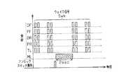
ウェイク信号Swkの間欠的な発信中において、モジュール51に設けられるアンロックスイッチ53が操作された場合には、図4に示すように、照合ECU71は、アンテナDF,DR,PF,PR,TLからのウェイク信号Swkの間欠発信を停止し、アンテナMLからのみウェイク信号Swkを発信する。このアンテナMLからのウェイク信号Swkの発信時間は、タイマ71bの作動時間である2秒間とされている。電子キー80が車外通信エリアSmlに進入している場合、照合ECU71と電子キー80との間では、先の車外通信と同様の無線通信が行われる。 When the
充電ECU75は、アンロックスイッチ53の操作を契機とした車外照合が成立すると、ロック機構41をアンロック状態に切り替えるとともに、タイマ75bを作動させる。これにより、給電プラグ10とインレット31とが接続されている場合、インレット31から給電プラグ10を取り外すことができる。なお、タイマ75bが作動中において、インレット31から給電プラグ10が取り外されない場合には、充電ECU75は、ロック機構41を再度ロック状態に切り替える。 The
次に、スマートシステムの作用について説明する。
照合ECU71は、アンテナDF,DR,PF,PR,TLを駆動させてウェイク信号Swkを間欠的に発信させている。このとき、アンテナMLの駆動は停止されている。これに対し、照合ECU71は、アンロックスイッチ53が操作された場合に、アンテナDF,DR,PF,PR,TLからのウェイク信号Swkの発信を一時的に停止させるとともに、アンテナMLのみからウェイク信号Swkを発信させる。すなわち、アンテナMLが車外通信エリアSmlへ向けてウェイク信号Swk及びチャレンジ信号Schを発信するタイミングは、アンテナDF,DR,PF,PR,TLが車外通信エリアSdf,Spf,Sdr,Spr,Stlへ向けてLF帯のウェイク信号Swk及びチャレンジ信号Schを発信するタイミングと異なる。従って、本例の車外通信エリアSmlは、その一部が車外通信エリアSdr,Stlと重なっているものの、重なっているエリアには、片方のアンテナからのみLF帯の無線信号が発信される。すなわち、LF帯の無線信号が重ならないため、干渉が発生しない。これにより、車外通信エリアが重なっているエリアにおいて、車両1と電子キー80との間の無線信号の授受が好適に行われる。Next, the operation of the smart system will be described.
The verification ECU 71 drives the antennas DF, DR, PF, PR, TL to intermittently transmit the wake signal Swk. At this time, the driving of the antenna ML is stopped. On the other hand, when the
以上詳述したように、本実施形態によれば、以下に示す効果が得られる。
(1)アンロックスイッチ53の操作を通じて、給電プラグ10をインレット31から取り外す旨のユーザ意志が確認された場合において、アンテナMLからLF帯の無線信号を発信するとき、アンテナDF,DR,PF,PR,TLからLF帯の無線信号は発信されない。このため、アンテナMLから発信する無線信号は、アンテナDF,DR,PF,PR,TLから発信される無線信号と干渉しない。従って、アンテナMLを介して電子キー80と車両1(照合ECU71)との間の無線信号の授受は好適に行われる。これにより、給電プラグ10の取り外しにかかる無線通信の信頼性、ひいては、ロック機構41の動作の信頼性を確保することができる。As described above in detail, according to the present embodiment, the following effects can be obtained.
(1) When the user's intention to remove the power supply plug 10 from the
(2)アンテナMLからの無線信号(ウェイク信号Swk)の発信は、アンロックスイッチ53が操作されたことを契機として行われる。換言すれば、アンロックスイッチ53が操作されない限りアンテナMLから無線信号が発信されることはなくアンテナDF,DR,PF,PR,TLからウェイク信号Swkが間欠発信される。このため、ドアの施解錠を実行するときの電子キー80と車両1との間の無線信号の授受は好適に行われる。従って、ドアの施解錠に係る無線通信の信頼性を確保することができる。 (2) The transmission of the radio signal (wake signal Swk) from the antenna ML is performed when the
(3)充電ECU75に、ロック機構41がアンロック状態とされたことを契機として始動するタイマ75bを設けた。そして、充電ECU75は、タイマ75bの起動中に給電プラグ10がインレット31から取り外されなければ、ロック機構41を再度ロック状態にするようにした。このため、ユーザが、ロック機構41をアンロック状態とした後、何らかの理由で給電プラグ10をインレット31から取り外すことなく車両を離れた場合、ロック機構41は自動的に再度ロック状態となる。これにより、ユーザが離れているときに給電プラグ10が不正に取り外されることを抑制することができる。 (3) The charging
なお、上記実施形態は以下のように変更してもよい。
・上記実施形態において、アンロックスイッチ53は省略してもよい。この場合、アンテナDF,DR,PF,PR,TLとは異なるタイミングでアンテナMLからウェイク信号Swkを間欠発信させるようにする。このように構成しても、アンテナMLから発信される無線信号は、アンテナDF,DR,PF,PR,TLから発信される無線信号と干渉することが抑制される。In addition, you may change the said embodiment as follows.
In the above embodiment, the
・上記実施形態において、タイマ75bは省略してもよい。このように構成しても、上記実施形態の(1),(2)の効果と同様の効果を得ることができる。
・上記実施形態では、アンテナMLは、モジュール51に設けたが、インレット31近傍に無線信号を発信すれば、その搭載位置はこれに限らない。例えば、ロック機構41やインレット31の周辺における車両1の内壁等に設けてもよい。このように構成しても上記実施形態と同様の効果を得ることができる。In the above embodiment, the timer 75b may be omitted. Even if comprised in this way, the effect similar to the effect of (1), (2) of the said embodiment can be acquired.
In the above embodiment, the antenna ML is provided in the
・上記実施形態において、タイマ75bの起動時間は30秒に設定されたが、この時間は任意に変更してもよい。なお、この時間は、ユーザ以外による給電プラグの不正な取り外しを防止する観点から、数十秒程度に設定することが望ましい。 In the above embodiment, the activation time of the timer 75b is set to 30 seconds, but this time may be arbitrarily changed. Note that this time is desirably set to about several tens of seconds from the viewpoint of preventing unauthorized removal of the power plug by a user other than the user.
・上記実施形態において、タイマ75bの起動時間は2秒に設定されたが、この時間は任意に変更してもよい。なお、この時間は、ユーザによるドアの施解錠の利便性を確保する観点から、数秒程度に設定することが望ましい。 In the above embodiment, the activation time of the timer 75b is set to 2 seconds, but this time may be arbitrarily changed. In addition, it is desirable to set this time to about several seconds from the viewpoint of ensuring the convenience of locking and unlocking the door by the user.
・上記各実施形態において、外部電源91からバッテリ4へ充電する際の制御は、充電ECU75にて行ったが、照合ECU71が行ってもよい。この場合、充電ECU75は、不要となる。 In each of the above embodiments, the control when charging the
・上記各実施形態において、インレット31は車両1の後方右側面に設けるようにしたが、これに限らず、後方左側面や前方両側面、車両前面等に設けてもよい。
・上記各実施形態において、電子キーシステム70で使用する電波の周波数は、必ずしもLFやUHFに限定されず、これら以外の周波数が使用可能である。また、車両1から電子キー80に電波発信するときの周波数と、電子キー80から車両1に電波を返すときの周波数とは、必ずしも異なるものに限定されず、これらを同じ周波数としてもよい。In each of the above embodiments, the
In each of the above embodiments, the frequency of the radio wave used in the electronic
・上記各実施形態において、プラグインハイブリッド式の車両1のインレット31に適用したが、プラグインハイブリッド式の車両に限らず、電気自動車のインレット等に適用してもよい。 In each of the above embodiments, the present invention is applied to the
DF,DR,ML,PF,PR,TL…アンテナ、Sac…アック信号、Sch…チャレンジ信号、Swk…ウェイク信号Sid…IDコード信号、Sdf,Sdr,Sml,Spf…車外通信エリア、1…車両、2…駆動輪、3…ハイブリッドシステム、4…バッテリ、6…コンバータ、8DF,8DR,8PF,8PR,8TL…ドア、10…給電プラグ、12…接続ケーブル、31…インレット、41…ロック機構、43…挿入検出装置、51…モジュール、53…アンロックスイッチ、70…電子キーシステム、71…照合ECU、71a,81a…メモリ、71b,75b…タイマ、72…車外LF発信機、73…車内LF発信機、74…UHF受信機、75…制御装置としての充電ECU、80…電子キー、81…通信制御部、82…LF受信部、83…UHF発信部、90…充電システム、91…外部電源、92…充電スイッチ。DF, DR, ML, PF, PR, TL ... antenna, Sac ... ACK signal, Sch ... challenge signal, Swk ... wake signal Sid ... ID code signal, Sdf, Sdr, Sml, Spf ... outside vehicle communication area, 1 ... vehicle, 2 ... Driving wheel, 3 ... Hybrid system, 4 ... Battery, 6 ... Converter, 8DF, 8DR, 8PF, 8PR, 8TL ... Door, 10 ... Feeding plug, 12 ... Connection cable, 31 ... Inlet, 41 ... Lock mechanism, 43 ... Insertion detecting device, 51 ... Module, 53 ... Unlock switch, 70 ... Electronic key system, 71 ... Verification ECU, 71a, 81a ... Memory, 71b, 75b ... Timer, 72 ... Outside LF transmitter, 73 ... Inside LF transmission , 74 ... UHF receiver, 75 ... Charge ECU as control device, 80 ... Electronic key, 81 ... Communication control unit, 2 ... LF reception unit, 83 ... UHF transmitter unit, 90 ... charging system, 91 ... external power supply, 92 ... charging switch.
Claims (3)
Translated fromJapanese前記車両は、前記電子キーに対して応答を要求する無線信号を発信するアンテナを複数個備え、そのうちの一つは、前記給電プラグの取り外しの許可に係る応答を要求する無線信号を発信するもの、他のアンテナは、ドアの解錠の実行又は許可に係る応答を要求する無線信号を発信するものとし、
前記制御装置は、駐車中は通常、一のアンテナを通じた前記給電プラグの取り外しに係る無線信号の送信を停止した状態に維持しつつ、前記他のアンテナを通じてドアの解錠に係る無線信号を送信する一方で、前記給電プラグの取り外しにかかる無線信号を送信する際には、ドアの解錠に係る無線信号の発信を停止する給電プラグのロック装置。Unauthorized removal of the power plug that is mounted on a vehicle equipped with an authentication function that executes or permits the unlocking of the door through the exchange of radio signals with the electronic key. While regulating, in the locking device of the power supply plug comprising a control device that permits the removal of the power supply plug from the inlet through the authentication function,
The vehicle includes a plurality of antennas that transmit wireless signals that request a response to the electronic key, one of which transmits a wireless signal that requests a response related to permission to remove the power plug. The other antenna shall transmit a radio signal requesting a response relating to execution or permission of door unlocking,
The control device normally transmits a radio signal related to unlocking the door through the other antenna while maintaining a state where transmission of the radio signal related to removal of the power supply plug through the one antenna is stopped during parking. On the other hand, when transmitting a radio signal related to removal of the power plug, the power plug lock device stops transmission of a radio signal related to unlocking the door.
前記車両は、前記給電プラグを前記インレットから取り外すときに操作されるスイッチを備え、
前記制御装置は、前記スイッチが操作されたとき、ドアの解錠に係る無線信号の送信を停止するとともに、前記給電プラグの取り外しに係る無線信号を送信する給電プラグのロック装置。The power plug locking device according to claim 1,
The vehicle includes a switch operated when the power plug is removed from the inlet,
When the switch is operated, the control device stops transmission of a wireless signal related to unlocking the door and transmits a wireless signal related to removal of the power supply plug.
前記制御装置は、前記給電プラグの前記インレットからの取り外しを許可したことを契機として前記給電プラグの取り外しに要すると想定される時間に基づき設定される一定期間だけ作動するタイマを備え、同タイマの作動中に前記給電プラグが前記インレットから取り外されなければ、再度前記給電プラグの前記インレットからの取り外しを規制する給電プラグのロック装置。The power plug locking device according to claim 1 or 2,
The control device includes a timer that operates for a certain period set based on a time that is assumed to be required to remove the power supply plug when the power supply plug is allowed to be removed from the inlet. A power plug locking device that restricts removal of the power plug from the inlet again if the power plug is not removed from the inlet during operation.
Priority Applications (3)
| Application Number | Priority Date | Filing Date | Title |
|---|---|---|---|
| JP2011154135AJP5658103B2 (en) | 2011-07-12 | 2011-07-12 | Power plug lock device |
| US13/542,919US8816815B2 (en) | 2011-07-12 | 2012-07-06 | Lock device for power supplying plug |
| CN201210251597.8ACN102882070B (en) | 2011-07-12 | 2012-07-10 | Lock device for power supplying plug |
Applications Claiming Priority (1)
| Application Number | Priority Date | Filing Date | Title |
|---|---|---|---|
| JP2011154135AJP5658103B2 (en) | 2011-07-12 | 2011-07-12 | Power plug lock device |
Publications (2)
| Publication Number | Publication Date |
|---|---|
| JP2013019192A JP2013019192A (en) | 2013-01-31 |
| JP5658103B2true JP5658103B2 (en) | 2015-01-21 |
Family
ID=47483301
Family Applications (1)
| Application Number | Title | Priority Date | Filing Date |
|---|---|---|---|
| JP2011154135AExpired - Fee RelatedJP5658103B2 (en) | 2011-07-12 | 2011-07-12 | Power plug lock device |
Country Status (3)
| Country | Link |
|---|---|
| US (1) | US8816815B2 (en) |
| JP (1) | JP5658103B2 (en) |
| CN (1) | CN102882070B (en) |
Families Citing this family (42)
| Publication number | Priority date | Publication date | Assignee | Title |
|---|---|---|---|---|
| JP2012080646A (en)* | 2010-09-30 | 2012-04-19 | Tokai Rika Co Ltd | Power feeding plug locking device |
| JP5922565B2 (en) | 2012-12-13 | 2016-05-24 | 株式会社東海理化電機製作所 | Locking device |
| JP5878457B2 (en) | 2012-12-13 | 2016-03-08 | 株式会社東海理化電機製作所 | Charging cable lock device |
| JP5902602B2 (en) | 2012-12-13 | 2016-04-13 | 株式会社東海理化電機製作所 | Locking device |
| JP5947202B2 (en) | 2012-12-13 | 2016-07-06 | 株式会社東海理化電機製作所 | Locking device |
| JP6068120B2 (en)* | 2012-12-13 | 2017-01-25 | 株式会社東海理化電機製作所 | Locking device |
| US9475399B2 (en)* | 2013-02-20 | 2016-10-25 | General Electric Company | Power conduit, charging device, and method of charging a power storage device |
| CN105121217B (en)* | 2013-04-15 | 2017-06-09 | 丰田自动车株式会社 | Vehicle |
| JP5937542B2 (en)* | 2013-05-15 | 2016-06-22 | 株式会社城南製作所 | Vehicle cover opening / closing control device |
| DE102013010283A1 (en)* | 2013-06-19 | 2014-12-24 | Audi Ag | Connection device for an electrical system of a vehicle and method for its operation |
| JP5958432B2 (en)* | 2013-07-23 | 2016-08-02 | トヨタ自動車株式会社 | vehicle |
| WO2015155838A1 (en) | 2014-04-08 | 2015-10-15 | 日産自動車株式会社 | Contactless electricity supply system and contactless electricity reception device |
| JP6471469B2 (en)* | 2014-11-18 | 2019-02-20 | 株式会社デンソー | Charging stand and power supply system |
| US20160257198A1 (en) | 2015-03-02 | 2016-09-08 | Ford Global Technologies, Inc. | In-vehicle component user interface |
| US9747740B2 (en) | 2015-03-02 | 2017-08-29 | Ford Global Technologies, Llc | Simultaneous button press secure keypad code entry |
| CN107529345B (en)* | 2015-04-07 | 2018-11-02 | 日产自动车株式会社 | Locking and system for unlocking |
| US9910467B2 (en) | 2015-05-01 | 2018-03-06 | International Business Machines Corporation | Lid and power supply interlock mechanism |
| US9914418B2 (en) | 2015-09-01 | 2018-03-13 | Ford Global Technologies, Llc | In-vehicle control location |
| US9967717B2 (en) | 2015-09-01 | 2018-05-08 | Ford Global Technologies, Llc | Efficient tracking of personal device locations |
| US9622159B2 (en) | 2015-09-01 | 2017-04-11 | Ford Global Technologies, Llc | Plug-and-play interactive vehicle interior component architecture |
| US9860710B2 (en) | 2015-09-08 | 2018-01-02 | Ford Global Technologies, Llc | Symmetrical reference personal device location tracking |
| US9744852B2 (en) | 2015-09-10 | 2017-08-29 | Ford Global Technologies, Llc | Integration of add-on interior modules into driver user interface |
| US10046637B2 (en) | 2015-12-11 | 2018-08-14 | Ford Global Technologies, Llc | In-vehicle component control user interface |
| KR101736998B1 (en)* | 2016-02-01 | 2017-05-17 | 현대자동차주식회사 | Electric vehicle charging connector anti-theft method and apparatus |
| US9827950B2 (en)* | 2016-03-14 | 2017-11-28 | Ford Global Technologies, Llc | Locking assembly and method with authenticated unlocking of electric vehicle supply equipment |
| US10082877B2 (en) | 2016-03-15 | 2018-09-25 | Ford Global Technologies, Llc | Orientation-independent air gesture detection service for in-vehicle environments |
| US9914415B2 (en) | 2016-04-25 | 2018-03-13 | Ford Global Technologies, Llc | Connectionless communication with interior vehicle components |
| DE102017203504A1 (en)* | 2017-03-03 | 2018-09-06 | Volkswagen Aktiengesellschaft | A method for unlocking a charging plug in connection with a charging operation of an electrically driven vehicle |
| CN107215222B (en)* | 2017-05-22 | 2020-02-28 | 北京汽车股份有限公司 | Automatic induction electric vehicle charging method and system |
| KR101857407B1 (en)* | 2018-01-30 | 2018-06-20 | (주)에프티글로벌 | A wireless power transfer system of identifying a position of the automated guided vehicle and method for identifying a position of the automated Guided Vehicle |
| US11117484B2 (en)* | 2018-05-09 | 2021-09-14 | Byton Limited | Safe and secure charging of a vehicle |
| US11447028B2 (en)* | 2018-06-05 | 2022-09-20 | Ford Global Technologies, Llc | Charger authorized removal method and authorized removal system |
| JP6764453B2 (en)* | 2018-09-27 | 2020-09-30 | 本田技研工業株式会社 | Body front structure |
| CN109888572B (en)* | 2018-12-27 | 2020-12-04 | 蔚来(安徽)控股有限公司 | Charging gun locking system and unlocking method thereof |
| JP7172608B2 (en)* | 2019-01-08 | 2022-11-16 | トヨタ自動車株式会社 | vehicle |
| US10861301B1 (en)* | 2019-06-24 | 2020-12-08 | Zealio Electronics Co., Ltd. | Multifunctional smart holder and control method thereof |
| DE102020101019A1 (en)* | 2020-01-17 | 2021-07-22 | Phoenix Contact E-Mobility Gmbh | Connector part with a sensor device |
| JP7415663B2 (en)* | 2020-02-28 | 2024-01-17 | トヨタ自動車株式会社 | Vehicle and charging system |
| DE102020125339A1 (en) | 2020-09-29 | 2022-03-31 | Dr. Ing. H.C. F. Porsche Aktiengesellschaft | charging station |
| US11462066B2 (en) | 2020-10-20 | 2022-10-04 | Honda Motor Co., Ltd. | System and method for locking a charging port to charge an electric vehicle |
| CN114379392B (en)* | 2022-03-24 | 2022-06-07 | 长安新能源南京研究院有限公司 | Intelligent lock control method and device for electric vehicle charging gun and storage medium |
| WO2024033979A1 (en)* | 2022-08-08 | 2024-02-15 | 住友電気工業株式会社 | Charging system, charging device, lock control method, and lock control program |
Family Cites Families (24)
| Publication number | Priority date | Publication date | Assignee | Title |
|---|---|---|---|---|
| US5202617A (en) | 1991-10-15 | 1993-04-13 | Norvik Technologies Inc. | Charging station for electric vehicles |
| JP3192715B2 (en)* | 1991-12-04 | 2001-07-30 | 富士通テン株式会社 | Wireless door lock control device for vehicles |
| JP3135040B2 (en) | 1995-11-30 | 2001-02-13 | 矢崎総業株式会社 | Electric vehicle charging connector |
| DE19642687C2 (en) | 1996-10-16 | 1999-08-05 | Daimler Chrysler Ag | Locking device for securing a charging socket |
| WO2005021905A1 (en) | 2003-09-01 | 2005-03-10 | Matsushita Electric Industrial Co., Ltd. | Vehicle unlocking system |
| JP2005194799A (en) | 2004-01-08 | 2005-07-21 | Tokai Rika Co Ltd | Smart entry system, and method for releasing state of locking oneself out |
| KR100699721B1 (en) | 2005-12-05 | 2007-03-26 | 에스앤티대우(주) | Car Passive Doors / Starters |
| JP4353197B2 (en)* | 2006-03-13 | 2009-10-28 | トヨタ自動車株式会社 | Vehicles and electrical equipment |
| JP4317861B2 (en) | 2006-08-31 | 2009-08-19 | 株式会社東海理化電機製作所 | Hybrid vehicle travel mode setting device |
| JP2008121254A (en)* | 2006-11-10 | 2008-05-29 | Calsonic Kansei Corp | Automatic unlocking method of vehicle keyless device |
| DE102007002025A1 (en) | 2007-01-13 | 2008-07-17 | Daimler Ag | Vehicle for use with modular system that is equipped with combustion engine and electro motor drive, has car body chassis, and chassis opening is accessible from chassis outer side and closed by cover |
| US8239103B2 (en)* | 2007-10-10 | 2012-08-07 | Toyota Jidosha Kabushiki Kaisha | Vehicle control device and control method |
| JP5259220B2 (en)* | 2008-03-25 | 2013-08-07 | 富士重工業株式会社 | Electric car |
| WO2010100081A2 (en) | 2009-03-03 | 2010-09-10 | Rwe Ag | Method and device for charging electrical vehicles |
| DE102009016504A1 (en) | 2009-04-08 | 2011-04-21 | Rwe Ag | Charging cable locking device and method for locking a cable |
| US8774997B2 (en)* | 2009-04-23 | 2014-07-08 | Toyota Jidosha Kabushiki Kaisha | Vehicle, charging cable, and charging system for vehicle |
| WO2010137144A1 (en) | 2009-05-28 | 2010-12-02 | トヨタ自動車株式会社 | Charging system |
| DE102009030092A1 (en) | 2009-06-22 | 2010-12-30 | Rwe Ag | Charging cable plug for electric vehicles |
| JP5170113B2 (en)* | 2009-07-24 | 2013-03-27 | 株式会社デンソー | Vehicle door control system, vehicle door control device, and vehicle door control device program |
| DE102009034886A1 (en) | 2009-07-27 | 2011-02-03 | Rwe Ag | Charging cable plug for connecting an electric vehicle to a charging station |
| JP5231381B2 (en)* | 2009-11-17 | 2013-07-10 | 株式会社東海理化電機製作所 | Connector lock structure for battery charging power receiving connector |
| JP5096518B2 (en)* | 2010-05-12 | 2012-12-12 | 株式会社東海理化電機製作所 | Power supply plug lock device |
| US8075329B1 (en)* | 2010-06-08 | 2011-12-13 | Ford Global Technologies, Llc | Method and system for preventing disengagement between an electrical plug and a charge port on an electric vehicle |
| US8690591B2 (en)* | 2011-06-09 | 2014-04-08 | GM Global Technology Operations LLC | Electric vehicle with secondary charge cord release mechanism |
- 2011
- 2011-07-12JPJP2011154135Apatent/JP5658103B2/ennot_activeExpired - Fee Related
- 2012
- 2012-07-06USUS13/542,919patent/US8816815B2/ennot_activeExpired - Fee Related
- 2012-07-10CNCN201210251597.8Apatent/CN102882070B/ennot_activeExpired - Fee Related
Also Published As
| Publication number | Publication date |
|---|---|
| CN102882070B (en) | 2015-01-21 |
| US8816815B2 (en) | 2014-08-26 |
| CN102882070A (en) | 2013-01-16 |
| JP2013019192A (en) | 2013-01-31 |
| US20130015951A1 (en) | 2013-01-17 |
Similar Documents
| Publication | Publication Date | Title |
|---|---|---|
| JP5658103B2 (en) | Power plug lock device | |
| JP6447610B2 (en) | Vehicle control system and vehicle control device | |
| US9495819B2 (en) | Lock device and electronic key system for use with vehicle charging inlet | |
| JP5508220B2 (en) | Electronic key system | |
| JP5548090B2 (en) | Power supply plug lock device | |
| JP5432192B2 (en) | Electronic key system | |
| US20140167915A1 (en) | Lock device, lock device controller, and electric key system | |
| US20140159857A1 (en) | Lock controller and electronic key system for vehicle | |
| US20140200757A1 (en) | Onboard system, electronic key system, and control unit | |
| US9377764B2 (en) | Plug lock device | |
| JP2014124027A (en) | Plug lock device | |
| US20140165675A1 (en) | Lock device, lock device controller, and electronic key system | |
| JP5660022B2 (en) | Charging cable lock control system, in-vehicle device, and power supply device | |
| JP6323298B2 (en) | Electronic key system and portable device | |
| US20140022053A1 (en) | Lock device | |
| JP4396687B2 (en) | Vehicle control system | |
| JP2015078536A (en) | Electronic key system | |
| JP2014151846A (en) | Power consumption reduction device for vehicle | |
| JP4534566B2 (en) | Vehicle remote control device | |
| JP4952358B2 (en) | Vehicle user verification system | |
| JP2010132233A (en) | Electronic-key leaving suppression system | |
| JP2004162477A (en) | In-vehicle device control device, vehicle control system, and vehicle communication system | |
| JP5502769B2 (en) | Electronic key system | |
| JP6253003B1 (en) | Electronic key system, security unit used in the system, and electronic key | |
| JP2008273520A (en) | Engine start controlling system |
Legal Events
| Date | Code | Title | Description |
|---|---|---|---|
| A621 | Written request for application examination | Free format text:JAPANESE INTERMEDIATE CODE: A621 Effective date:20140226 | |
| A977 | Report on retrieval | Free format text:JAPANESE INTERMEDIATE CODE: A971007 Effective date:20141105 | |
| TRDD | Decision of grant or rejection written | ||
| A01 | Written decision to grant a patent or to grant a registration (utility model) | Free format text:JAPANESE INTERMEDIATE CODE: A01 Effective date:20141118 | |
| A61 | First payment of annual fees (during grant procedure) | Free format text:JAPANESE INTERMEDIATE CODE: A61 Effective date:20141127 | |
| R150 | Certificate of patent or registration of utility model | Ref document number:5658103 Country of ref document:JP Free format text:JAPANESE INTERMEDIATE CODE: R150 | |
| LAPS | Cancellation because of no payment of annual fees |