JP5657609B2 - Breathing gas supply device - Google Patents
Breathing gas supply deviceDownload PDFInfo
- Publication number
- JP5657609B2 JP5657609B2JP2012141651AJP2012141651AJP5657609B2JP 5657609 B2JP5657609 B2JP 5657609B2JP 2012141651 AJP2012141651 AJP 2012141651AJP 2012141651 AJP2012141651 AJP 2012141651AJP 5657609 B2JP5657609 B2JP 5657609B2
- Authority
- JP
- Japan
- Prior art keywords
- oxygen gas
- gas supply
- extraction unit
- unit
- supply unit
- Prior art date
- Legal status (The legal status is an assumption and is not a legal conclusion. Google has not performed a legal analysis and makes no representation as to the accuracy of the status listed.)
- Active
Links
Images


Landscapes
- Filling Or Discharging Of Gas Storage Vessels (AREA)
Description
Translated fromJapanese本発明は、呼吸用気体供給装置に関し、詳しくは、各種医療用酸素ガス供給源からの酸素を呼吸器系疾患を持つ患者に供給する際に使用する呼吸用気体供給装置に関する。 The present invention relates to a breathing gas supply device, and more particularly to a breathing gas supply device used when oxygen from various medical oxygen gas supply sources is supplied to a patient having a respiratory disease.
肺気腫や慢性気管支炎等の呼吸器系疾患を持つ患者が在宅時や外出時に酸素を吸入するための機器として、小型で携帯可能なFRP製の医療用酸素ガス容器が一般的に用いられている。この医療用酸素ガス容器には、カニューラを介して吸入する酸素ガスの圧力や流量を調節するための減圧弁や流量調節弁を備えた呼吸用気体供給装置が取り付けられている。この呼吸用気体供給装置として、減圧手段及び流量設定手段を備えた容器ユニット部と、デマンドレギュレーターを備えたセーバーユニット部とに分割し、医療用酸素ガス容器に取り付けられる容器ユニット部に対してセーバーユニット部を着脱可能とした一体型呼吸用気体供給装置が知られている(例えば、特許文献1参照。)。 As a device for inhaling oxygen when a patient with respiratory diseases such as emphysema and chronic bronchitis is at home or going out, a small and portable medical oxygen gas container made of FRP is generally used. . The medical oxygen gas container is provided with a breathing gas supply device including a pressure reducing valve and a flow rate adjusting valve for adjusting the pressure and flow rate of oxygen gas sucked through the cannula. This breathing gas supply device is divided into a container unit portion provided with a decompression means and a flow rate setting means and a saver unit portion provided with a demand regulator, and saver is provided for a container unit portion attached to a medical oxygen gas container. An integrated breathing gas supply device in which a unit part is detachable is known (for example, see Patent Document 1).
特許文献1に記載された一体型呼吸用気体供給装置は、押し込むことによって容器ユニット部にセーバーユニット部を合体させるための合体惹起手段と、押し込むことによって容器ユニット部からセーバーユニット部を分離させるための解除惹起手段とを設けているため、構造が複雑になるだけでなく、合体させるときには、容器ユニット部に対してセーバーユニット部を位置合わせしてずれたりしないように押し付けた状態で合体惹起手段を押し込まなければならず、操作性に難点があり、高齢者などの負担になっていた。また、両方とも押し込むことで合体させたり、合体を解除させたりするものであるため、押し間違いにより合体や解除がスムーズにいかないこともあった。さらに、セーバーユニット部を使用中に、何らかの原因で解除惹起手段が押し込まれた状態になると、容器ユニット部からセーバーユニット部が外れてしまい、カニューラへの呼吸用気体の供給が絶たれてしまうおそれがあった。 The integrated breathing gas supply device described in
なお、前記特許文献1では、請求項1において流量設定手段が容器ユニット部に備えられていると記載しているにもかかわらず、発明の実施の形態では、流量設定つまみがセーバーユニット部に備えられていると記載しているため、容器ユニット部及びセーバーユニット部の構成が明確ではない。 In addition, in the said
そこで本発明は、医療用酸素ガス容器をはじめとする各種医療用酸素ガスの酸素ガス取出口に固着される酸素ガス取出ユニットと、カニューラなどが接続されるガス供給ユニットとの着脱を容易かつ確実に行うことができ、呼吸用気体を安定した状態で確実に供給することができる呼吸用気体供給装置を提供することを目的としている。 Therefore, the present invention provides easy and reliable attachment / detachment between an oxygen gas extraction unit fixed to an oxygen gas outlet of various medical oxygen gases including a medical oxygen gas container and a gas supply unit to which a cannula is connected. It is an object of the present invention to provide a breathing gas supply device that can be performed in a stable manner and can reliably supply the breathing gas in a stable state.
上記目的を達成するため、本発明の呼吸用気体供給装置は、医療用酸素ガス供給源から供給される酸素ガスを流量調節して使用者に供給する呼吸用気体供給装置において、前記医療用酸素ガス供給源の酸素ガス取出口に固着される酸素ガス取出ユニットと、該酸素ガス取出ユニットに着脱可能に結合するガス供給ユニットとを備え、前記酸素ガス取出ユニットは、該酸素ガス取出ユニットに前記ガス供給ユニットが結合しているときにのみ開弁する逆止弁を備え、前記ガス供給ユニットは、前記酸素ガス取出ユニットからガス供給ユニットに導入された酸素ガスの流量を設定する流量調節弁を備え、酸素ガス取出ユニット及びガス供給ユニットは、互いに係合して酸素ガス取出ユニットとガス供給ユニットとを結合させる係合手段をそれぞれ備え、前記酸素ガス取出ユニットは、前記係合手段の係合状態を解除して酸素ガス取出ユニットとガス供給ユニットとを分離可能とする係合解除手段及び該係合解除手段の係合解除動作を規制する係合解除規制手段を備え、前記ガス供給ユニットは、前記流量調節弁で設定した酸素ガスの流量がゼロに設定されているときに、前記係合解除規制手段による前記係合解除手段の係合解除動作の規制を解除する規制解除手段を備え、前記係合手段は、前記ガス供給ユニットに設けられた係合突部を有する雄側係合部材と、前記酸素ガス取出ユニットに設けられた前記雄側係合部材の係合突部に対して係合位置と非係合位置とに移動可能に形成された雌側係合部材と、前記雌側係合部材を前記非係合位置に押動する前記係合解除手段である押動部材とを備えていることを特徴としている。
In order to achieve the above object, the breathing gas supply device of the present invention is the breathing gas supply device for supplying oxygen to a user by adjusting the flow rate of oxygen gas supplied from a medical oxygen gas supply source. An oxygen gas extraction unit fixed to an oxygen gas extraction port of a gas supply source; and a gas supply unit detachably coupled to the oxygen gas extraction unit, wherein the oxygen gas extraction unit includes the oxygen gas extraction unit. A check valve that opens only when the gas supply unit is coupled, and the gas supply unit includes a flow rate adjustment valve that sets a flow rate of oxygen gas introduced from the oxygen gas extraction unit to the gas supply unit. The oxygen gas extraction unit and the gas supply unit are engaged with each other by engaging means for coupling the oxygen gas extraction unit and the gas supply unit, respectively. The oxygen gas extraction unit releases the engagement state of the engagement means so that the oxygen gas extraction unit and the gas supply unit can be separated, and the engagement release operation of the engagement release means. Disengagement restricting means that restricts the disengagement means by the disengagement restricting means when the flow rate of oxygen gas set by the flow rate control valve is set to zero. And a restriction release means for releasing the restriction of the engagement release operation, wherein the engagement means is provided on the male side engagement member having an engagement protrusion provided on the gas supply unit, and on the oxygen gas extraction unit. A female engagement member formed to be movable between an engagement position and a non-engagement position with respect to the engagement protrusion of the male engagement member, and the female engagement member is disengaged Pushing member that is the disengaging means that pushes into position It is characterized inthat it comprises a.
また、本発明の呼吸用気体供給装置は、医療用酸素ガス供給源から供給される酸素ガスを流量調節して使用者に供給する呼吸用気体供給装置において、前記医療用酸素ガス供給源の酸素ガス取出口に固着される酸素ガス取出ユニットと、該酸素ガス取出ユニットに着脱可能に結合するガス供給ユニットとを備え、前記酸素ガス取出ユニットは、該酸素ガス取出ユニットに前記ガス供給ユニットが結合しているときにのみ開弁する逆止弁を備え、前記ガス供給ユニットは、前記酸素ガス取出ユニットからガス供給ユニットに導入された酸素ガスの流量を設定する流量調節弁を備え、酸素ガス取出ユニット及びガス供給ユニットは、互いに係合して酸素ガス取出ユニットとガス供給ユニットとを結合させる係合手段をそれぞれ備え、前記酸素ガス取出ユニットは、前記係合手段の係合状態を解除して酸素ガス取出ユニットとガス供給ユニットとを分離可能とする係合解除手段及び該係合解除手段の係合解除動作を規制する係合解除規制手段を備え、前記ガス供給ユニットは、前記流量調節弁で設定した酸素ガスの流量がゼロに設定されているときに、前記係合解除規制手段による前記係合解除手段の係合解除動作の規制を解除する規制解除手段を備え、前記酸素ガス取出ユニット及び前記ガス供給ユニットは、それぞれ形成された結合面を当接させた状態で結合し、前記係合手段は、ガス供給ユニットの結合面から酸素ガス取出ユニットに向けて突設され、先端部側面に係合突部が設けられた雄側係合部材と、酸素ガス取出ユニットの結合面に設けられて前記雄側係合部材が進入する保持孔の側壁部に前記酸素ガス取出口の軸線と直交する方向に移動して前記雄側係合部材の係合突部に対して係合位置と非係合位置とに移動可能に形成された雌側係合部材とを備え、前記雌側係合部材は、前記非係合位置において前記酸素ガス取出ユニットの結合面の外周面より突出するように形成され、前記雌側係合部材の色調と異なる色調の非係合表示部を上面に設けていることを特徴としている。The breathing gas supply device of the present invention is a breathing gas supply device that adjusts the flow rate of oxygen gas supplied from a medical oxygen gas supply source and supplies the oxygen gas to a user. An oxygen gas extraction unit fixed to the gas extraction port; and a gas supply unit detachably coupled to the oxygen gas extraction unit. The oxygen gas extraction unit is connected to the oxygen gas extraction unit. A check valve that opens only when the gas supply unit is open, and the gas supply unit includes a flow rate adjustment valve that sets a flow rate of oxygen gas introduced from the oxygen gas extraction unit to the gas supply unit, The unit and the gas supply unit each include engagement means for engaging with each other to couple the oxygen gas extraction unit and the gas supply unit, The exit unit releases the engagement state of the engagement means to disengage the oxygen gas extraction unit and the gas supply unit, and the engagement restricts the disengagement operation of the disengagement means. Disengaging operation of the disengagement means by the disengagement restriction means when the flow rate of oxygen gas set by the flow rate control valve is set to zero. The oxygen gas extraction unit and the gas supply unit are coupled in a state where the formed coupling surfaces are in contact with each other, and the engagement unit is coupled to the gas supply unit. A male-side engaging member that protrudes from the surface toward the oxygen gas extraction unit and has an engagement protrusion on the side surface of the tip, and a male-side engagement member that is provided on the coupling surface of the oxygen gas extraction unit. Keep entering It is formed on the side wall of the hole so as to move in a direction perpendicular to the axis of the oxygen gas outlet and move between an engagement position and a non-engagement position with respect to the engagement protrusion of the male engagement member. A female engagement member, and the female engagement member is formed so as to protrude from the outer peripheral surface of the coupling surface of the oxygen gas extraction unit at the non-engagement position. And a disengagement display portion having a color tone different from that of the first embodiment is provided on the upper surface.
前記雌側係合部材は、前記係合位置において前記酸素ガス取出ユニットの結合面の外周面と面一になる外側面を有することが好ましい。
The female engagement member preferablyhas an outer surface that isflush with the outer peripheral surface of the coupling surface of the oxygen gas extraction unit at the engagement position .
また、本発明の呼吸用気体供給装置は、医療用酸素ガス供給源から供給される酸素ガスを流量調節して使用者に供給する呼吸用気体供給装置において、前記医療用酸素ガス供給源の酸素ガス取出口に固着される酸素ガス取出ユニットと、該酸素ガス取出ユニットに着脱可能に結合するガス供給ユニットとを備え、前記酸素ガス取出ユニットは、該酸素ガス取出ユニットに前記ガス供給ユニットが結合しているときにのみ開弁する逆止弁を備え、前記ガス供給ユニットは、前記酸素ガス取出ユニットからガス供給ユニットに導入された酸素ガスの流量を設定する流量調節弁を備え、酸素ガス取出ユニット及びガス供給ユニットは、互いに係合して酸素ガス取出ユニットとガス供給ユニットとを結合させる係合手段をそれぞれ備え、前記酸素ガス取出ユニットは、前記係合手段の係合状態を解除して酸素ガス取出ユニットとガス供給ユニットとを分離可能とする係合解除手段及び該係合解除手段の係合解除動作を規制する係合解除規制手段を備え、前記ガス供給ユニットは、前記流量調節弁で設定した酸素ガスの流量がゼロに設定されているときに、前記係合解除規制手段による前記係合解除手段の係合解除動作の規制を解除する規制解除手段を備え、前記酸素ガス取出ユニット及び前記ガス供給ユニットは、前記酸素ガス取出口の軸線と直交する方向にそれぞれ形成された結合面を当接させた状態で結合し、前記酸素ガス取出口の軸線方向に分離可能に形成され、前記係合手段は、ガス供給ユニットの結合面から酸素ガス取出ユニットに向けて突設され、先端部側面に係合突部が設けられた雄側係合部材と、酸素ガス取出ユニットの結合面に設けられて前記雄側係合部材が進入する保持孔の側壁部に前記酸素ガス取出口の軸線と直交する方向に移動して前記雄側係合部材の係合突部に対して係合位置と非係合位置とに移動可能に形成された雌側係合部材と、該雌側係合部材を前記非係合位置から前記係合位置に向けて付勢する雌側係合部材付勢手段と、前記酸素ガス取出口の軸線と直交する方向に移動して前記雌側係合部材を前記非係合位置に押動する前記係合解除手段である押動部材と、前記酸素ガス取出口の軸線方向に移動して前記押動部材が前記雌側係合部材を前記非係合位置に押動する方向に移動することを規制する押動規制位置と押動規制解除位置とに移動可能に設けられて前記押動規制位置では酸素ガス取出ユニットの結合面からガス供給ユニットに向けて突出した状態になる前記係合解除規制手段である押動規制部材と、該押動規制部材を前記押動規制位置に付勢する押動規制部材付勢手段とを備えていることを特徴としている。さらに、前記雄側係合部材は、先端部で雌側係合部材を雌側係合部材付勢手段の付勢力に抗して前記非係合位置に押動し、前記係合突部に対して雌側係合部材が係合可能な位置まで雄側係合部材を保持孔内に進入させたときに、雌側係合部材付勢手段の付勢力によって雌側係合部材が係合突部との係合位置に移動して雄側係合部材と雌側係合部材とが係合して酸素ガス取出ユニットとガス供給ユニットとを結合状態に保持し、前記流量調節弁は、前記酸素ガス取出口の軸線方向の回転軸を中心として回転する流量調節ダイヤルをガス供給ユニットの外周部に備え、該流量調節ダイヤルの結合面側には、酸素ガスの流量をゼロに設定したときに前記押動規制部材を前記押動規制解除位置に移動させる前記規制解除手段が設けられていることが好ましい。The breathing gas supply device of the present invention is a breathing gas supply device that adjusts the flow rate of oxygen gas supplied from a medical oxygen gas supply source and supplies the oxygen gas to a user. An oxygen gas extraction unit fixed to the gas extraction port; and a gas supply unit detachably coupled to the oxygen gas extraction unit. The oxygen gas extraction unit is connected to the oxygen gas extraction unit. A check valve that opens only when the gas supply unit is open, and the gas supply unit includes a flow rate adjustment valve that sets a flow rate of oxygen gas introduced from the oxygen gas extraction unit to the gas supply unit, The unit and the gas supply unit each include engagement means for engaging with each other to couple the oxygen gas extraction unit and the gas supply unit, The exit unit releases the engagement state of the engagement means to disengage the oxygen gas extraction unit and the gas supply unit, and the engagement restricts the disengagement operation of the disengagement means. Disengaging operation of the disengagement means by the disengagement restriction means when the flow rate of oxygen gas set by the flow rate control valve is set to zero. The oxygen gas extraction unit and the gas supply unit are coupled in a state in which the coupling surfaces formed in the direction perpendicular to the axis of the oxygen gas outlet are in contact with each other. The oxygen gas outlet is formed to be separable in the axial direction, and the engagement means protrudes from the coupling surface of the gas supply unit toward the oxygen gas extraction unit, and an engagement protrusion is provided on the side surface of the tip portion. The male side engaging member is moved to a side wall portion of a holding hole which is provided on the coupling surface of the oxygen gas extracting unit and the male side engaging member enters in a direction perpendicular to the axis of the oxygen gas outlet. A female engagement member formed to be movable between an engagement position and a non-engagement position with respect to the engagement protrusion of the male engagement member; and the female engagement member from the non-engagement position. A female-side engagement member urging means that urges toward the engagement position, and moves in a direction perpendicular to the axis of the oxygen gas outlet to push the female-side engagement member to the non-engagement position And a pushing member that is the disengaging means that moves in the axial direction of the oxygen gas outlet, and the pushing member moves in a direction to push the female engagement member to the disengaged position. It is provided so as to be movable between a push restricting position that restricts this and a push restrict releasing position, and at the push restricting position, an oxygen gas extraction unit is provided. A push restricting member as the disengagement restricting means that protrudes from the coupling surface of the base plate toward the gas supply unit, and a push restricting member that biases the push restricting member to the push restricting position And an urging means. Further, the male side engaging member pushes the female side engaging member to the disengaged position against the urging force of the female side engaging member urging means atthe tip, and On the other hand, when the male engagement member is advanced into the holding hole to a position where the female engagement member can be engaged, the female engagement member is engaged by the urging force of the female engagement member urging means. The male side engaging member and the female side engaging member are engaged to move to the engaging position with the protrusion, and the oxygen gas extraction unit and the gas supply unit are held in a coupled state. When a flow rate adjustment dial that rotates about the axis of rotation of the oxygen gas outlet in the axial direction is provided on the outer periphery of the gas supply unit, the flow rate of oxygen gas is set to zero on the coupling surface side of the flow rate adjustment dial Preferably, the restriction release means for moving the push restriction member to the push restriction release position is provided. Arbitrariness.
前記ガス供給ユニットが、該ガス供給ユニットから供給する酸素ガスを連続して供給する連続供給と、酸素ガスを呼吸に同調させて供給する同調供給とを切り替える供給状態切替手段を備えていることが好ましい。 The gas supply unit includes supply state switching means for switching between continuous supply for continuously supplying oxygen gas supplied from the gas supply unit and synchronized supply for supplying oxygen gas in synchronization with respiration. preferable.
前記医療用酸素ガス供給源が、酸素ガスを高圧充填した医療用酸素ガス容器の場合、前記酸素ガス取出ユニットは、前記医療用酸素ガス容器から導出された酸素ガスを減圧する減圧弁、前記医療用酸素ガス容器からの酸素ガス導出経路を開閉する容器元弁、前記医療用酸素ガス容器内の酸素ガスの残量を表示する残量計、前記医療用酸素ガス容器内に酸素ガスを充填する充填口、前記医療用酸素ガス容器内の圧力が上昇したときに開弁する安全弁及び前記医療用酸素ガス容器から取り出した酸素ガス中の塵埃を除去するフィルタを備えていることが好ましく、前記酸素ガス取出口の軸線が、前記医療用酸素ガス容器の軸線と一致していることが好ましい。 When the medical oxygen gas supply source is a medical oxygen gas container filled with oxygen gas at a high pressure, the oxygen gas extraction unit includes a pressure reducing valve that decompresses the oxygen gas derived from the medical oxygen gas container, and the medical A container main valve that opens and closes an oxygen gas lead-out path from the medical oxygen gas container, a fuel gauge that displays the remaining amount of oxygen gas in the medical oxygen gas container, and the medical oxygen gas container is filled with oxygen gas It is preferable to include a filling port, a safety valve that opens when the pressure in the medical oxygen gas container increases, and a filter that removes dust in oxygen gas taken out from the medical oxygen gas container. It is preferable that the axis of the gas outlet coincides with the axis of the medical oxygen gas container.
本発明の呼吸用気体供給装置によれば、ガス供給ユニットが結合しているときにのみ開弁する逆止弁を酸素ガス取出ユニットが備えているので、ガス供給ユニットが結合していないときには、医療用酸素ガス供給源から外部に酸素ガスが流出することはなく、流量調節弁の酸素ガス流量がゼロ以外では係合手段の解除を行えないので、酸素ガスを使用中にガス供給ユニットが酸素ガス取出ユニットから外れて呼吸用気体の供給が途絶えることがない。さらに、酸素ガスの供給量がゼロで呼吸用気体を使用していないときには、ガス供給ユニットを容易に取り外すことができ、取り外したガス供給ユニットは、他の医療用酸素ガス供給源に取り付けられている酸素ガス取出ユニットに取り付けることができるので、例えば、複数の医療用酸素ガス容器に酸素ガス取出ユニットをそれぞれ固着しておくことにより、使用する医療用酸素ガス容器の交換を容易に行うことができる。さらに、複数の異なる医療用酸素ガス供給源にあらかじめ酸素ガス取出ユニットをそれぞれ固着しておくことにより、使用者の状況に応じた適宜な医療用酸素ガス供給源を選択して利用することができる。例えば、在宅時と外出時とで、それぞれ最適な医療用酸素ガス供給源を利用することができる。また、ガス供給ユニットに連続供給と同調供給とを切り替える供給状態切替手段を設けておくことにより、使用状態に応じた供給状態で呼吸用気体を使用者に供給することができる。 According to the breathing gas supply device of the present invention, since the oxygen gas extraction unit includes a check valve that opens only when the gas supply unit is coupled, when the gas supply unit is not coupled, Since the oxygen gas does not flow out from the medical oxygen gas supply source and the engagement means cannot be released unless the oxygen gas flow rate of the flow rate control valve is zero, the gas supply unit can There is no interruption in the supply of breathing gas from the gas extraction unit. Furthermore, when the supply amount of oxygen gas is zero and the breathing gas is not used, the gas supply unit can be easily removed, and the removed gas supply unit is attached to another medical oxygen gas supply source. For example, by attaching the oxygen gas extraction unit to each of a plurality of medical oxygen gas containers, it is possible to easily replace the medical oxygen gas container to be used. it can. Furthermore, by attaching the oxygen gas extraction unit to a plurality of different medical oxygen gas supply sources in advance, it is possible to select and use an appropriate medical oxygen gas supply source according to the user's situation. . For example, an optimal medical oxygen gas supply source can be used at home and when going out. Moreover, by providing the gas supply unit with supply state switching means for switching between continuous supply and synchronized supply, the breathing gas can be supplied to the user in a supply state corresponding to the use state.
さらに、係合手段を酸素ガス取出口の軸線方向に押し付けるように移動させて係合するように形成することにより、ガス供給ユニットを酸素ガス取出ユニットに取り付ける際の操作性を向上させることができ、片手で行うことも可能となる。一方、係合解除手段を酸素ガス取出口の軸線と直交する方向に移動して係合手段の係合を解除するように形成することにより、酸素ガス取出ユニットからガス供給ユニットを取り外す際の操作性を向上でき、片手で取り外すことも可能となる。 Furthermore, the operability when the gas supply unit is attached to the oxygen gas extraction unit can be improved by moving the engagement means so as to be pressed in the axial direction of the oxygen gas extraction port. It can also be done with one hand. On the other hand, an operation for removing the gas supply unit from the oxygen gas extraction unit by moving the engagement release means in a direction orthogonal to the axis of the oxygen gas outlet and releasing the engagement of the engagement means. Can be improved and can be removed with one hand.
さらに、医療用酸素ガス供給源が医療用酸素ガス容器の場合は、酸素ガス取出ユニットに容器元弁を設けておくことにより、非使用時の医療用酸素ガス容器を確実に密閉状態としておくことができ、残量計を設けておくことにより、医療用酸素ガス容器内の酸素ガス量を容易に確認することができる。さらに、充填口を設けておくことにより、酸素ガス取出ユニットを装着したままの状態で医療用酸素ガス容器内への酸素ガスの充填を行うことができ、安全弁を設けておくことにより、何らかの原因で容器内圧力が上昇しても安全であり、フィルタを設けておくことにより、塵埃を含んだ酸素ガスが呼吸用気体として使用者に供給されることもなくなる。 Furthermore, when the medical oxygen gas supply source is a medical oxygen gas container, a container oxygen valve is provided in the oxygen gas take-out unit to ensure that the medical oxygen gas container is kept sealed when not in use. By providing a fuel gauge, the amount of oxygen gas in the medical oxygen gas container can be easily confirmed. Furthermore, by providing a filling port, oxygen gas can be filled into the medical oxygen gas container with the oxygen gas take-out unit attached, and by providing a safety valve, any cause Thus, it is safe even if the pressure in the container rises, and by providing a filter, oxygen gas containing dust is not supplied to the user as a breathing gas.
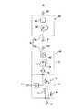
本形態例は、本発明の呼吸用気体供給装置を、酸素ガスを高圧で充填した医療用酸素ガス容器(以下、ガス容器という。)に適用した一形態例を示している。本形態例に示す呼吸用気体供給装置10は、ガス容器11における酸素ガス取出口である口金部11aに固着されてガス容器11の容器弁を兼ねる酸素ガス取出ユニット30と、該酸素ガス取出ユニット30に着脱可能に結合するガス供給ユニット50とで構成されており、酸素ガス取出ユニット30及びガス供給ユニット50の内部には、ガス容器11内から導出した酸素ガスを使用者に供給するための酸素ガス導出経路70が設けられている。 This embodiment shows an embodiment in which the breathing gas supply device of the present invention is applied to a medical oxygen gas container (hereinafter referred to as a gas container) filled with oxygen gas at a high pressure. The breathing
酸素ガス取出ユニット30の酸素ガス導出経路70aは、容器弁部71と減圧部72とを備えており、容器弁部71には、酸素ガス導出経路70aをガス容器11内に連通させる容器連通部73と、酸素ガス導出経路70aを開閉する容器元弁74と、ガス容器11内の圧力に対応してガス容器11内の酸素ガスの残量を表示する残量計75と、ガス容器11内の圧力があらかじめ設定された上限圧力を超えたときに開弁する安全弁76と、ガス容器11内に酸素ガスを充填するための充填口77とが設けられている。 The oxygen
また、減圧部72には、ガス容器11内から導出した高圧の酸素ガスをあらかじめ設定された圧力に減圧するための減圧弁78と、酸素ガス導出経路70aを流れる酸素ガス中の塵埃を除去するフィルタ79と、酸素ガス取出ユニット30にガス供給ユニット50が結合しているときにのみ開弁する逆止弁80とが設けられ、逆止弁80の下流側の酸素ガス導出経路70aの端部には、ガス供給ユニット50内の酸素ガス導出経路70bの端部に設けられた雄側継手部81に着脱可能に接続する雌側継手部82が設けられている。 The
一方のガス供給ユニット50内の酸素ガス導出経路70bには、使用者に供給する酸素ガスの流量を設定する流量調節弁83と、酸素ガスの供給状態を連続供給状態と同調供給状態とに切り替える供給状態切替手段84とが設けられ、酸素ガス導出経路70bの出口部にはジョイント接続部85が設けられている。 In the oxygen gas lead-out path 70b in one
酸素ガス取出ユニット30とガス供給ユニット50とは、ガス容器11の酸素ガス取出口の軸線、本形態例では、酸素ガス取出口の軸線と一致するガス容器11の軸線と直交する方向、すなわち、ガス容器11を立てた状態で水平方向に向くようにそれぞれ形成された円盤状の結合面31,51を当接させた状態で結合し、ガス容器11の軸線方向、ガス容器11を立てた状態で上下方向に分離可能に形成されている。 The oxygen gas take-out
さらに、酸素ガス取出ユニット30の外面には、前記容器元弁74を開閉するための開閉コック32と、前記残量計75の表示部である残量表示部33と、図示は省略するが、前記充填口77の開口と、減圧弁78の調整部とが設けられている。また、酸素ガス取出ユニット30の下部には、酸素ガス取出ユニット30をガス容器11の口金部11aに螺着するための雄ねじ部34が設けられている。 Furthermore, on the outer surface of the oxygen
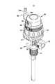
一方のガス供給ユニット50は、円柱状の外形を有するもので、酸素ガス取出ユニット結合側となる下向き結合面51に近い外周面には、前記流量調節弁83を操作するための流量設定リング52が水平方向に回動可能に設けられ、該流量設定リング52の上部には、流量調節弁83に設定した酸素ガス流量を数値で表示する流量表示部53が呼吸用気体供給装置の正面を向いて設けられている。 One
さらに、流量表示部53の上部には、前記供給状態切替手段84の供給切替操作部54と供給状態表示部55とが設けられ、ガス供給ユニット50の外周面一側には、前記ジョイント接続部85に連結されたジョイント56が設けられている。このジョイント56は、ジョイント接続部85との連結部56aからチューブ接続部56bを直角に屈曲させたL字状に形成されており、連結部56aがジョイント接続部85に対して回動可能に形成されており、カニューラのチューブ12を接続するのに適した任意の方向にチューブ接続部56bを回動できるようにしている。 Further, a supply
また、上向き結合面31の中央と下向き結合面51の中央とには、前記雄側継手部81,雌側継手部82の連結端35,57がそれぞれ開口しており、酸素ガス取出ユニット30とガス供給ユニット50とを結合したときに、連結端35,57が気密に嵌合するように形成されている。 Further, at the center of the
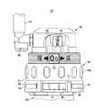
酸素ガス取出ユニット30とガス供給ユニット50とを結合状態に保持するための係合手段は、ガス供給ユニット50の下向き結合面51から酸素ガス取出ユニット30に向かって突出し、先端部側面に係合突部58がそれぞれ設けられた一対の雄側係合部材59と、酸素ガス取出ユニット30の上向き結合面31に設けられた一対の保持孔36の側壁部にそれぞれ設けられた雌側係合部材37とを備えている。 Engagement means for holding the oxygen
係合突部58は、雄側係合部材59の側面から下向き結合面51の径方向外側に向かって突出しており、係合突部58の下向き結合面51側には、雌側係合部材37が係合する水平方向の段部58aが形成され、係合突部58の酸素ガス取出ユニット30側先端部には、先端から次第に下向き結合面51の外周側に向かう方向の斜面からなるガイド面58bが形成されている。 The
雌側係合部材37は、上向き結合面31内の両側面に開口するようにしてそれぞれ設けられた水平方向の係合部材支持溝38内に設けられており、雌側係合部材37の前後方向中間部が、上下方向を向いた軸部材39によって回動可能に軸支されている。雌側係合部材37の軸部材39より後部側には、前記保持孔36内に出没可能な係合部37aが形成され、軸部材39より前部側には、係合解除用アーム37bが形成されている。 The
前記係合部37aの内側面は、雄側係合部材59のガイド面58bと同じ方向に傾斜したガイド面37cが形成され、外側面37dは、上向き結合面31の外周面と面一になる円弧状に形成されている。また、両雌側係合部材37の内周側には、前記係合部37aを保持孔36内に突出させる方向に付勢する雌側係合部材付勢手段である板バネ40が設けられている。 A
これにより、雌側係合部材37は、板バネ40の付勢力で押動されて保持孔36内に係合部37aが突出した係合位置と、板バネ40の付勢力に抗して保持孔36から係合部37aが没して外側面37dが上向き結合面31の外周より外方に突出した状態の非係合位置とに回動可能に形成されている。また、非係合位置で上向き結合面31の外周より外方に突出した状態となる雌側係合部材37の先端部上面には、雌側係合部材37の色調とは異なった色調で、雌側係合部材37が非係合位置にあることを示す非係合表示部37eが設けられている。 Thus, the
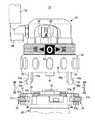
さらに、上向き結合面31の正面側下部には、前記雌側係合部材37の係合部37aを保持孔36から係合部材支持溝38内に没する方向に回動させて、前記雄側係合部材59と雌側係合部材37との係合状態を解除するための係合解除手段である係合解除部材41を収容する係合解除部材収容溝42が水平方向に設けられている。係合解除部材41の内側面両端部は、前記係合解除用アーム37bの外面に当接しており、係合解除用アーム37bを介して前記板バネ40により外周側に付勢されている。 Further, on the lower part on the front side of the
係合解除部材41の内側面中央部の内側部分には、上下方向のガイド溝43が設けられており、該ガイド溝43内に、係合解除部材41が内側に押動されて移動することを規制するための押動規制部材44が上下方向に移動可能に設けられている。この押動規制部材44は、ガイド溝43の底部に設けられた押動規制部材付勢手段であるコイルバネ45によって上方に付勢されており、通常は、押動規制部材44の上端が上向き結合面31から上方に突出した状態に保持されている。 A
押動規制部材44の前面中央部には、前記係合解除部材41の内側面中央部が進入可能な凹溝44aが前方に向かって開口しており、押動規制部材44がガイド溝43に沿って下方に押し込まれ、押動規制部材44の上端が上向き結合面31と面一になったときに、凹溝44a内に係合解除部材41が進入可能な状態となるように形成されている。 A
一方、前記流量設定リング52の内周には、上向き結合面31から突出した前記押動規制部材44の上部を収納可能なリング状凹溝52aが設けられており、該リング状凹溝52aの一部に、前記押動規制部材44を下方に向けて押動するための規制解除手段となる押圧突起60が設けられている。この押圧突起60は、流量設定リング52を酸素ガス流量の設定値がゼロとなる位置に回動させたときに、押動規制部材44を下方に押圧するものであって、流量設定リング52を酸素ガス流量の設定値がゼロ以外の位置としたときには押圧突起60が押動規制部材44の位置から外れて押動規制部材44がリング状凹溝52a内に突出した状態となるように形成されている。 On the other hand, on the inner periphery of the flow
また、酸素ガス取出ユニット30とガス供給ユニット50とを結合する際の位置合わせ用として、各雄側係合部材59の内側面後部側に上下方向のガイド突片59aがそれぞれ設けられ、下向き結合面51の後部側にはガイド突起61が突設されるとともに、各保持孔36の内側壁部に前記ガイド突片59aが進入するガイド溝36aがそれぞれ設けられ、上向き結合面31の後部側にはガイド突起61が進入するガイド凹部46が設けられている。 In addition, for alignment when the oxygen
さらに、流量設定リング52の外周面には、流量設定リング52を回動させる際の操作性を向上させるため、複数の滑り止め突起52bが周方向に設けられており、流量表示部53の流量表示は、ゼロのみを白抜きとしてゼロ以外との識別を確実に行えるようにしている。また、酸素ガス取出ユニット30における前記開閉コック32の開閉表示面32aや残量表示部33も色分けするなどして視認性を向上させている。 Further, on the outer peripheral surface of the flow
このように形成した呼吸用気体供給装置は、複数のガス容器11の口金部11aに酸素ガス取出ユニット30をそれぞれ固着したままの状態で使用され、酸素ガス取出ユニット30にガス供給ユニット50を結合して使用する。通常、酸素ガス取出ユニット30を装着したガス容器11は、充填口77から酸素ガスを充填され、開閉コック32を閉じて酸素ガス取出ユニット30及び口金部11aをフィルムなどの密封部材で密封した状態で使用者の手元に届けられる。 The breathing gas supply device formed in this way is used in a state where the oxygen
使用者は、密封部材を取り除いた後、係合解除部材41を手前に向けた状態の酸素ガス取出ユニット30の上方から、流量表示部53を手前に向けた状態のガス供給ユニット50を酸素ガス取出ユニット30に押し付けることにより、酸素ガス取出ユニット30にガス供給ユニット50を結合させる。このとき、酸素ガス取出ユニット30の方向とガス供給ユニット50の方向とが合っていない場合は、雄側係合部材59のガイド突片59aが保持孔36のガイド溝36aに入らず、ガイド突起61もガイド凹部46に入らないため、ガス供給ユニット50を酸素ガス取出ユニット30に結合させることができず、誤った状態でガス供給ユニット50が酸素ガス取出ユニット30に組み付けられることはない。 After removing the sealing member, the user moves the
酸素ガス取出ユニット30の方向とガス供給ユニット50の方向とが合っている場合は、雄側係合部材59が保持孔36内に進入するとともにガイド突片59aがガイド溝36aに進入し、保持孔36内に進入した雄側係合部材59の先端のガイド面58bが雌側係合部材37のガイド面37cに摺接し、板バネ40の付勢力に抗して雌側係合部材37の係合部37aを外側に押し拡げて雌側係合部材37を非係合位置に回動させる。係合突部58が係合部37aの下方に通過すると、板バネ40の付勢力で雌側係合部材37が係合位置に復帰し、保持孔36内に突出した係合部37aが係合突部58の段部58aに係合することにより、酸素ガス取出ユニット30とガス供給ユニット50とが結合状態に保持される。同時に、雄側継手部81及び雌側継手部82の連結端35,57が凹凸嵌合することによって逆止弁80が開いた状態となる。また、酸素ガス取出ユニット30とガス供給ユニット50との結合が完全に行われず、雌側係合部材37が非係合位置にあるときには、周辺の部材と異なる色調の前記非係合表示部37eが酸素ガス取出ユニット30の外周に突出したままになっているので、両ユニット30,50の結合状態が不十分であることを使用者に知らせることができる。 When the direction of the oxygen
ガス供給ユニット50を酸素ガス取出ユニット30に結合させた後、残量表示部33で残量を確認してから開閉コック32を開いてガス容器11内から酸素ガスを供給可能な状態とし、流量設定リング52を回して酸素ガスの流量をあらかじめ設定された流量に設定し、また、必要に応じて供給切替操作部54を操作して供給状態を切り替える。 After the
これにより、ガス容器11内の酸素ガスは、酸素ガス取出ユニット30における容器弁部71の開状態となった容器元弁74を通り、減圧部72の減圧弁78で所定圧力に減圧され、開状態となった逆止弁80を通り、雄側継手部81及び雌側継手部82を通ってガス供給ユニット50内に入り、流量調節弁83で所定流量に設定された後、チューブ12を介してカニューラに呼吸用気体として供給される。 As a result, the oxygen gas in the gas container 11 passes through the container
ガス容器11内の酸素ガスの残量が少なくなった場合は、開閉コック32を閉じるとともに、流量設定リング52を回して流量表示部53にゼロを表示させる。流量設定リング52をゼロの位置にすることにより、コイルバネ45の付勢力で使用中には上端部が上向き結合面31から上方に突出していた押動規制部材44を流量設定リング52に設けられた押圧突起60が下方に押圧し、押動規制部材44の凹溝44a内に係合解除部材41が進入可能な状態となる。 When the remaining amount of oxygen gas in the gas container 11 decreases, the open /
この状態で、板バネ40の付勢力に抗して係合解除部材41を正面から後方に向かって押動すると、押動規制部材44の内側面中央部が凹溝44a内に進入するとともに、係合解除部材41の内側面両端部が係合解除用アーム37bを後方に押動し、雌側係合部材37を軸部材39を中心に回動させて非係合位置とする。これにより、係合部37aが保持孔36の壁面内に没した状態となり、係合部37aと段部58aとの係合状態が解除され、酸素ガス取出ユニット30からガス供給ユニット50を取り外すことができる。 In this state, when the
一方、酸素ガス取出ユニット30からのガス供給ユニット50の取り外しは、流量設定リング52がゼロの位置にあるときしか行えないため、ガス容器11内の酸素ガスを呼吸用気体として使用中は、すなわち、流量設定リング52がゼロ以外に設定されているときには、押動規制部材44の上端部が流量設定リング52のリング状凹溝52a内に突出して凹溝44aが上方に移動しているので、押動規制部材44によって係合解除部材41の後方への移動が規制され、係合解除部材41によって雌側係合部材37を非係合位置に回動させることはできない。したがって、使用中にガス供給ユニット50が外れることはなく、酸素ガスの供給を確実に継続することができる。 On the other hand, since the
すなわち、流量をゼロに設定しなければガス供給ユニット50を取り外せないため、所定流量で酸素を供給している使用中にガス供給ユニット50が外れることはなく、予期せぬときに酸素ガスの供給が絶たれるおそれもない。さらに、使用者が確認する必要のある流量表示部53、供給状態表示部55、開閉コック32の開閉表示面32a、残量表示部33を全て正面から視認可能な状態としているので、使用中にもこれらを容易に確認することができる。 That is, since the
また、開閉コック32を閉じ位置に回すことを忘れてガス供給ユニット50を取り外してしまった場合は、酸素ガス取出ユニット30の酸素ガス導出経路70aに、酸素ガス取出ユニット30にガス供給ユニット50を結合しときにのみ開弁する逆止弁80が設けられているため、酸素ガス取出ユニット30の連結端35から酸素ガスが噴出することはなく、安全性を確保できるとともに、酸素ガスが無駄に消費されることを防止できる。万一、逆止弁80が故障してガス供給ユニット50を取り外したときに閉じ状態にならなかったとしても、酸素ガス導出経路70aに設けた減圧弁78で十分に減圧されているため、ガス容器11内に高圧充填された酸素ガスが急激に噴出することはない。 If the
このように、酸素ガス取出ユニット30にガス供給ユニット50を結合させる際には、ガス供給ユニット50をガス容器11の軸線方向上方からまっすぐに酸素ガス取出ユニット30に押し付けるだけでよく、他の操作を全く必要としないため、ガス供給ユニット50の結合を片手でも容易に行うことができる。また、酸素ガス取出ユニット30からガス供給ユニット50を取り外す際には、流量設定リング52で流量をゼロに設定して係合解除部材41を正面から押し込むだけでよく、ガス供給ユニット50の取り外しも簡単な操作で容易に行うことができる。 In this way, when the
したがって、ガス容器11の交換に伴うガス供給ユニット50の着脱を使用者が容易かつ短時間で行うこと可能となり、ガス容器11を交換する際の使用者の負担を軽減することができる。また、酸素ガスの充填などでガス容器11を搬送する際には、ガス容器11に酸素ガス取出ユニット30のみが取り付けられた状態で行うため、酸素ガス取出ユニット30はガス容器11の本数と同じ数を必要とするが、ガス供給ユニット50は使用者の人数分だけ用意すればよいことから、呼吸用気体供給装置10に要するコストだけでなく、医療費の削減を図ることができる。 Therefore, the user can easily attach and detach the
図15は、液体酸素を貯留した液体酸素容器から呼吸用気体を供給する液化酸素式医療用酸素ガス供給機に本発明の呼吸用気体供給装置を適用した一例を示している。液体酸素容器90から呼吸用気体を供給する場合、液体酸素容器90には、酸素ガスを供給するための機器として、蒸発器91,安全弁92及び圧力調節弁93があらかじめ設けられているので、酸素ガス取出ユニット94には逆止弁95を設けておくだけでよい。酸素ガス取出ユニット94に、前記同様に形成した雌側継手部82やガス供給ユニット50との結合構造を設けておくことにより、前記形態例で説明したガス供給ユニット50を、同じようにして着脱して用いることができる。 FIG. 15 shows an example in which the respiratory gas supply device of the present invention is applied to a liquefied oxygen medical oxygen gas supply device that supplies a respiratory gas from a liquid oxygen container that stores liquid oxygen. When supplying the breathing gas from the
なお、呼吸用気体供給装置における各部の構造、形状は任意であり、例えば、供給状態切替手段を省略することもできる。前記形態例では、医療用酸素ガス供給源として、高圧の酸素を充填した医療用酸素ガス容器及び液体酸素容器内の液体酸素を蒸発器で気化させた酸素ガスを供給する液化酸素式医療用酸素ガス供給機を例示したが、医療用酸素ガス供給源には、病院内に設けられている院内アウトレットバルブ、病院内で使用される院内酸素ボンベなどの各種医療用酸素ガス供給源に対応することが可能である。さらには、PSA式酸素濃縮装置、膜式酸素濃縮装置などの酸素濃縮装置に装着して使用することもできる。 In addition, the structure and shape of each part in the breathing gas supply device are arbitrary, and for example, the supply state switching means can be omitted. In the embodiment, as a medical oxygen gas supply source, a medical oxygen gas container filled with high-pressure oxygen and a liquefied oxygen medical oxygen for supplying oxygen gas obtained by vaporizing liquid oxygen in the liquid oxygen container with an evaporator Although a gas supply machine was illustrated, the medical oxygen gas supply source should correspond to various medical oxygen gas supply sources such as a hospital outlet valve provided in the hospital and a hospital oxygen cylinder used in the hospital. Is possible. Furthermore, it can be used by being attached to an oxygen concentrator such as a PSA oxygen concentrator or a membrane oxygen concentrator.
また、酸素ガス取出ユニットに組み込まれる減圧弁は、医療用酸素ガス供給源からの酸素供給圧力が低い場合や医療用酸素ガス供給源に減圧弁が設けられている場合には、省略することができる。同様に、医療用酸素ガス供給源が、元弁、残量計、充填口、安全弁、フィルタを備えている場合は、これらを酸素ガス取出ユニットに設けなくてもよく、ガス供給ユニットの供給状態切替手段を省略することもできる。 The pressure reducing valve incorporated in the oxygen gas extraction unit may be omitted when the oxygen supply pressure from the medical oxygen gas supply source is low or when the pressure reducing valve is provided in the medical oxygen gas supply source. it can. Similarly, when the medical oxygen gas supply source includes a main valve, a fuel gauge, a filling port, a safety valve, and a filter, these may not be provided in the oxygen gas extraction unit, and the supply state of the gas supply unit The switching means can be omitted.
さらに、前記形態例では、ガス容器の軸線と酸素ガス取出口の軸線とが一致しているガス容器を使用した場合の最適な構造を例示したが、ガス容器の軸線と酸素ガス取出口の軸線とが交わる場合は、酸素ガス取出口の軸線を基準として前記同様の構造を採用することが好ましい。 Furthermore, in the said embodiment, although the optimal structure at the time of using the gas container with which the axis line of a gas container and the axis line of an oxygen gas extraction port corresponded was illustrated, the axis line of a gas container and the axis line of an oxygen gas extraction port In the case of crossing, it is preferable to adopt the same structure as described above with reference to the axis of the oxygen gas outlet.
10…呼吸用気体供給装置、11…医療用酸素ガス容器、11a…口金部、12…チューブ、30…酸素ガス取出ユニット、31…上向き結合面、32…開閉コック、32a…開閉表示面、33…残量表示部、34…雄ねじ部、35…連結端、36…保持孔、36a…ガイド溝、37…雌側係合部材、37a…係合部、37b…係合解除用アーム、37c…ガイド面、37d…外側面、37e…非係合表示部、38…係合部材支持溝、39…軸部材、40…板バネ、41…係合解除部材、42…係合解除部材収容溝、43…ガイド溝、44…押動規制部材、44a…凹溝、45…コイルバネ、46…ガイド凹部、50…ガス供給ユニット、51…下向き結合面、52…流量設定リング、52a…リング状凹溝、52b…滑り止め突起、53…流量表示部、54…供給切替操作部、55…供給状態表示部、56…ジョイント、56a…連結部、56b…チューブ接続部、57…連結端、58…係合突部、58a…段部、58b…ガイド面、59…雄側係合部材、59a…ガイド突片、60…押圧突起、61…ガイド突起、70…酸素ガス導出経路、70a…酸素ガス取出ユニット30の酸素ガス導出経路、70b…ガス供給ユニット50内の酸素ガス導出経路、71…容器弁部、72…減圧部、73…容器連通部、74…容器元弁、75…残量計、76…安全弁、77…充填口、78…減圧弁、79…フィルタ、80…逆止弁、81…雄側継手部、82…雌側継手部、83…流量調節弁、84…供給状態切替手段、85…ジョイント接続部、90…液体酸素容器、91…蒸発器、92…安全弁、93…圧力調節弁、94…酸素ガス取出ユニット、95…逆止弁、96…ガス供給ユニット DESCRIPTION OF
Claims (13)
Translated fromJapanese前記係合手段は、
前記ガス供給ユニットに設けられた係合突部を有する雄側係合部材と、
前記酸素ガス取出ユニットに設けられた前記雄側係合部材の係合突部に対して係合位置と非係合位置とに移動可能に形成された雌側係合部材と、
前記雌側係合部材を前記非係合位置に押動する前記係合解除手段である押動部材と
を備えている呼吸用気体供給装置。In a breathing gas supply device for supplying oxygen gas supplied from a medical oxygen gas supply source to a user by adjusting the flow rate, an oxygen gas extraction unit fixed to an oxygen gas outlet of the medical oxygen gas supply source; A check valve that opens only when the gas supply unit is connected to the oxygen gas extraction unit. The gas supply unit includes a flow rate adjustment valve for setting a flow rate of oxygen gas introduced from the oxygen gas extraction unit to the gas supply unit, and the oxygen gas extraction unit and the gas supply unit are engaged with each other. Engaging means for coupling the oxygen gas take-out unit and the gas supply unit are provided, and the oxygen gas take-out unit is engaged with the engaging means. The disengagement means for disengaging the oxygen gas extraction unit and the gas supply unit and the disengagement restricting means for restricting the disengagement operation of the disengagement means, the gas supply unit comprising: When the flow rate of oxygen gas set by the flow rate control valve is set to zero, it comprises a restriction release means for releasing the restriction of the disengagement operation of the disengagement means by the disengagement restriction means,
The engaging means includes
A male engagement member having an engagement protrusion provided in the gas supply unit;
A female engagement member formed to be movable between an engagement position and a non-engagement position with respect to an engagement protrusion of the male engagement member provided in the oxygen gas extraction unit;
A pushing member as the disengaging means for pushing the female engagement member to the disengaged position;
A breathing gas supply device.
前記酸素ガス取出ユニット及び前記ガス供給ユニットは、それぞれ形成された結合面を当接させた状態で結合し、
前記係合手段は、
ガス供給ユニットの結合面から酸素ガス取出ユニットに向けて突設され、先端部側面に係合突部が設けられた雄側係合部材と、
酸素ガス取出ユニットの結合面に設けられて前記雄側係合部材が進入する保持孔の側壁部に前記酸素ガス取出口の軸線と直交する方向に移動して前記雄側係合部材の係合突部に対して係合位置と非係合位置とに移動可能に形成された雌側係合部材とを備え、
前記雌側係合部材は、前記非係合位置において前記酸素ガス取出ユニットの結合面の外周面より突出するように形成され、前記雌側係合部材の色調と異なる色調の非係合表示部を上面に設けている
呼吸用気体供給装置。In a breathing gas supply device for supplying oxygen gas supplied from a medical oxygen gas supply source to a user by adjusting the flow rate, an oxygen gas extraction unit fixed to an oxygen gas outlet of the medical oxygen gas supply source; A check valve that opens only when the gas supply unit is connected to the oxygen gas extraction unit. The gas supply unit includes a flow rate adjustment valve for setting a flow rate of oxygen gas introduced from the oxygen gas extraction unit to the gas supply unit, and the oxygen gas extraction unit and the gas supply unit are engaged with each other. Engaging means for coupling the oxygen gas take-out unit and the gas supply unit are provided, and the oxygen gas take-out unit is engaged with the engaging means. The disengagement means for disengaging the oxygen gas extraction unit and the gas supply unit and the disengagement restricting means for restricting the disengagement operation of the disengagement means, the gas supply unit comprising: When the flow rate of oxygen gas set by the flow rate control valve is set to zero, it comprises a restriction release means for releasing the restriction of the disengagement operation of the disengagement means by the disengagement restriction means,
The oxygen gas extraction unit and the gas supply unit are combined in a state in which the formed coupling surfaces are in contact with each other,
The engaging means includes
A male-side engagement member that protrudes from the coupling surface of the gas supply unit toward the oxygen gas extraction unit, and that has an engagement protrusion on the side surface of the tip.
The male side engaging member is engaged by moving in a direction perpendicular to the axis of the oxygen gas outlet port to a side wall portion of a holding hole that is provided on the coupling surface of the oxygen gas extracting unit and into which the male side engaging member enters. A female engagement member formed to be movable between an engagement position and a non-engagement position with respect to the protrusion,
The female engagement member is formed so as to protrude from the outer peripheral surface of the coupling surface of the oxygen gas extraction unit at the non-engagement position, and the non-engagement display unit having a color tone different from the color tone of the female engagement member. A breathing gas supply device.
前記酸素ガス取出ユニット及び前記ガス供給ユニットは、前記酸素ガス取出口の軸線と直交する方向にそれぞれ形成された結合面を当接させた状態で結合し、前記酸素ガス取出口の軸線方向に分離可能に形成され、
前記係合手段は、
ガス供給ユニットの結合面から酸素ガス取出ユニットに向けて突設され、先端部側面に係合突部が設けられた雄側係合部材と、
酸素ガス取出ユニットの結合面に設けられて前記雄側係合部材が進入する保持孔の側壁部に前記酸素ガス取出口の軸線と直交する方向に移動して前記雄側係合部材の係合突部に対して係合位置と非係合位置とに移動可能に形成された雌側係合部材と、
該雌側係合部材を前記非係合位置から前記係合位置に向けて付勢する雌側係合部材付勢手段と、
前記酸素ガス取出口の軸線と直交する方向に移動して前記雌側係合部材を前記非係合位置に押動する前記係合解除手段である押動部材と、
前記酸素ガス取出口の軸線方向に移動して前記押動部材が前記雌側係合部材を前記非係合位置に押動する方向に移動することを規制する押動規制位置と押動規制解除位置とに移動可能に設けられて前記押動規制位置では酸素ガス取出ユニットの結合面からガス供給ユニットに向けて突出した状態になる前記係合解除規制手段である押動規制部材と、
該押動規制部材を前記押動規制位置に付勢する押動規制部材付勢手段と
を備えている呼吸用気体供給装置。In a breathing gas supply device for supplying oxygen gas supplied from a medical oxygen gas supply source to a user by adjusting the flow rate, an oxygen gas extraction unit fixed to an oxygen gas outlet of the medical oxygen gas supply source; A check valve that opens only when the gas supply unit is connected to the oxygen gas extraction unit. The gas supply unit includes a flow rate adjustment valve for setting a flow rate of oxygen gas introduced from the oxygen gas extraction unit to the gas supply unit, and the oxygen gas extraction unit and the gas supply unit are engaged with each other. Engaging means for coupling the oxygen gas take-out unit and the gas supply unit are provided, and the oxygen gas take-out unit is engaged with the engaging means. The disengagement means for disengaging the oxygen gas extraction unit and the gas supply unit and the disengagement restricting means for restricting the disengagement operation of the disengagement means, the gas supply unit comprising: When the flow rate of oxygen gas set by the flow rate control valve is set to zero, it comprises a restriction release means for releasing the restriction of the disengagement operation of the disengagement means by the disengagement restriction means,
The oxygen gas take-out unit and the gas supply unit are coupled in a state where contact surfaces formed in a direction orthogonal to the axis of the oxygen gas take-out port are in contact with each other, and are separated in the axial direction of the oxygen gas take-out port Formed possible,
The engaging means includes
A male-side engagement member that protrudes from the coupling surface of the gas supply unit toward the oxygen gas extraction unit, and that has an engagement protrusion on the side surface of the tip.
The male side engaging member is engaged by moving in a direction perpendicular to the axis of the oxygen gas outlet port to a side wall portion of a holding hole that is provided on the coupling surface of the oxygen gas extracting unit and into which the male side engaging member enters. A female engagement member formed to be movable between an engagement position and a non-engagement position with respect to the protrusion;
Female-side engagement member urging means for urging the female-side engagement member from the non-engagement position toward the engagement position;
A pushing member that is the disengaging means that moves in a direction perpendicular to the axis of the oxygen gas outlet and pushes the female engagement member to the disengaged position;
A push restriction position and a push restriction release that move in the axial direction of the oxygen gas outlet and restrict the push member from moving in the direction of pushing the female engagement member to the non-engagement position. A push restricting member which is a disengagement restricting means which is provided so as to be movable to a position and protrudes from the coupling surface of the oxygen gas extraction unit toward the gas supply unit at the push restricting position;
A breathing gas supply device comprising: a pushing restriction member urging means for urging the pushing restriction member to the pushing restriction position.
前記流量調節弁は、前記酸素ガス取出口の軸線方向の回転軸を中心として回転する流量調節ダイヤルをガス供給ユニットの外周部に備え、該流量調節ダイヤルの結合面側には、酸素ガスの流量をゼロに設定したときに前記押動規制部材を前記押動規制解除位置に移動させる前記規制解除手段が設けられている請求項4記載の呼吸用気体供給装置。The male side engaging member pushes the female side engaging member to the non-engaging position against the urging force of the female side engaging member urging means atthe tip, and against the engaging protrusion When the male engagement member is advanced into the holding hole to a position where the female engagement member can be engaged, the female engagement member is engaged by the urging force of the female engagement member urging means. And the male engagement member and the female engagement member are engaged to hold the oxygen gas extraction unit and the gas supply unit in a coupled state.
The flow rate adjustment valve has a flow rate adjustment dial that rotates about the axis of rotation of the oxygen gas outlet in the axial direction on the outer periphery of the gas supply unit, and the flow rate of oxygen gas is on the coupling surface side of the flow rate adjustment dial.The breathing gas supply device according to claim 4, wherein the restriction release means is provided to move the push restriction member to the push restriction release position when the value is set to zero.
Priority Applications (1)
| Application Number | Priority Date | Filing Date | Title |
|---|---|---|---|
| JP2012141651AJP5657609B2 (en) | 2011-08-02 | 2012-06-25 | Breathing gas supply device |
Applications Claiming Priority (3)
| Application Number | Priority Date | Filing Date | Title |
|---|---|---|---|
| JP2011169052 | 2011-08-02 | ||
| JP2011169052 | 2011-08-02 | ||
| JP2012141651AJP5657609B2 (en) | 2011-08-02 | 2012-06-25 | Breathing gas supply device |
Publications (2)
| Publication Number | Publication Date |
|---|---|
| JP2013048888A JP2013048888A (en) | 2013-03-14 |
| JP5657609B2true JP5657609B2 (en) | 2015-01-21 |
Family
ID=47650155
Family Applications (1)
| Application Number | Title | Priority Date | Filing Date |
|---|---|---|---|
| JP2012141651AActiveJP5657609B2 (en) | 2011-08-02 | 2012-06-25 | Breathing gas supply device |
Country Status (2)
| Country | Link |
|---|---|
| JP (1) | JP5657609B2 (en) |
| CN (1) | CN202724398U (en) |
Families Citing this family (9)
| Publication number | Priority date | Publication date | Assignee | Title |
|---|---|---|---|---|
| CN103418069B (en)* | 2013-09-06 | 2015-09-30 | 肖永初 | Oxygenerator |
| CN104147669B (en)* | 2014-08-20 | 2017-05-24 | 徐象明 | Intelligent oxygen supply system |
| JP6654168B2 (en)* | 2017-06-30 | 2020-02-26 | 大陽日酸株式会社 | Respiratory gas supply device |
| JP2019084420A (en)* | 2019-03-15 | 2019-06-06 | 株式会社三幸製作所 | Gas flow rate controller for medical gas supply equipment |
| WO2020202638A1 (en)* | 2019-04-03 | 2020-10-08 | 中村 正一 | Oxygen inhaler |
| JP7389451B2 (en)* | 2019-07-12 | 2023-11-30 | 株式会社ネリキ | Opening/closing device and valve opening/closing system |
| KR102409694B1 (en)* | 2021-08-18 | 2022-06-16 | 맥센스 주식회사 | Oxygen mask for emergent escape |
| CN113713226B (en)* | 2021-09-07 | 2024-07-30 | 杨亚敏 | Portable intelligent oxygen supply structure |
| CN116182076A (en)* | 2023-03-06 | 2023-05-30 | 成都洛子科技有限公司 | High-efficiency oxygen supply device and oxygen supply method for filling cylinder |
Family Cites Families (5)
| Publication number | Priority date | Publication date | Assignee | Title |
|---|---|---|---|---|
| JP2579192Y2 (en)* | 1991-08-31 | 1998-08-20 | 株式会社ガスター | Cassette cooker safety device |
| JP2001276221A (en)* | 2000-03-28 | 2001-10-09 | Teijin Ltd | Gas supplying device for respiration and gas vessel for respiration |
| JP4647093B2 (en)* | 2000-12-25 | 2011-03-09 | 帝人株式会社 | Breathing gas supply device |
| JP4409817B2 (en)* | 2002-10-17 | 2010-02-03 | 帝人株式会社 | Integrated breathing gas supply device |
| JP2005147174A (en)* | 2003-11-11 | 2005-06-09 | Neriki:Kk | Flow rate setting unit for valve device |
- 2012
- 2012-06-25JPJP2012141651Apatent/JP5657609B2/enactiveActive
- 2012-08-02CNCN 201220382067patent/CN202724398U/ennot_activeExpired - Lifetime
Also Published As
| Publication number | Publication date |
|---|---|
| JP2013048888A (en) | 2013-03-14 |
| CN202724398U (en) | 2013-02-13 |
Similar Documents
| Publication | Publication Date | Title |
|---|---|---|
| JP5657609B2 (en) | Breathing gas supply device | |
| US11419993B2 (en) | Inhalator and inhalator set | |
| US11173271B2 (en) | Oxygen sensor assembly for medical ventilator | |
| JP2009528902A (en) | Adapter for use with anesthetic vaporizer | |
| CA2272538C (en) | Anesthetic vaporizer draining system | |
| KR20210098460A (en) | Liquid refill systems and refill bottles for aerosol inhalers | |
| JP5571388B2 (en) | Portable liquid oxygen storage unit | |
| US8291947B2 (en) | Water bottle adaptor for an appliance | |
| US6745800B1 (en) | Arrangement for preventing overfill of anesthetic liquid | |
| CN115708916A (en) | Anesthesia system and anesthesia component with anesthetic dispenser and locking device | |
| US7287548B2 (en) | Integrated valve assembly with means for blocking the actuator | |
| JP4673307B2 (en) | Resuscitator | |
| US20080236576A1 (en) | Method and apparatus for preventing drug reservoir overfill | |
| CN101361647A (en) | Multifunctional laryngoscope | |
| WO2001072364A1 (en) | Air feeding device for respiration | |
| JP2012521335A (en) | Device for transferring volatile liquid from container to inhaler | |
| JP2005176879A (en) | Respiratory oxygen supply device | |
| US9539406B2 (en) | Interface device and method for supplying gas flow for subject breathing and apparatus for supplying anesthetic agent to the interface device | |
| JP6654168B2 (en) | Respiratory gas supply device | |
| JP5918805B2 (en) | Packing mounting structure, packing and demand valve | |
| JP3207282U (en) | Small hydrogen gas inhaler | |
| JP4409817B2 (en) | Integrated breathing gas supply device | |
| JP2020006017A (en) | Medical oxygen supply device | |
| CN115671466A (en) | Adapter of anesthetic medicine bottle and anesthetic evaporation device |
Legal Events
| Date | Code | Title | Description |
|---|---|---|---|
| A621 | Written request for application examination | Free format text:JAPANESE INTERMEDIATE CODE: A621 Effective date:20131015 | |
| A977 | Report on retrieval | Free format text:JAPANESE INTERMEDIATE CODE: A971007 Effective date:20140704 | |
| A131 | Notification of reasons for refusal | Free format text:JAPANESE INTERMEDIATE CODE: A131 Effective date:20140708 | |
| A521 | Request for written amendment filed | Free format text:JAPANESE INTERMEDIATE CODE: A523 Effective date:20140908 | |
| TRDD | Decision of grant or rejection written | ||
| A01 | Written decision to grant a patent or to grant a registration (utility model) | Free format text:JAPANESE INTERMEDIATE CODE: A01 Effective date:20141104 | |
| A61 | First payment of annual fees (during grant procedure) | Free format text:JAPANESE INTERMEDIATE CODE: A61 Effective date:20141126 | |
| R150 | Certificate of patent or registration of utility model | Ref document number:5657609 Country of ref document:JP Free format text:JAPANESE INTERMEDIATE CODE: R150 | |
| R250 | Receipt of annual fees | Free format text:JAPANESE INTERMEDIATE CODE: R250 | |
| R250 | Receipt of annual fees | Free format text:JAPANESE INTERMEDIATE CODE: R250 | |
| R250 | Receipt of annual fees | Free format text:JAPANESE INTERMEDIATE CODE: R250 | |
| R250 | Receipt of annual fees | Free format text:JAPANESE INTERMEDIATE CODE: R250 | |
| S111 | Request for change of ownership or part of ownership | Free format text:JAPANESE INTERMEDIATE CODE: R313111 | |
| R350 | Written notification of registration of transfer | Free format text:JAPANESE INTERMEDIATE CODE: R350 | |
| R250 | Receipt of annual fees | Free format text:JAPANESE INTERMEDIATE CODE: R250 | |
| R250 | Receipt of annual fees | Free format text:JAPANESE INTERMEDIATE CODE: R250 | |
| R250 | Receipt of annual fees | Free format text:JAPANESE INTERMEDIATE CODE: R250 | |
| R250 | Receipt of annual fees | Free format text:JAPANESE INTERMEDIATE CODE: R250 |