JP5655648B2 - Electronic device and circuit board connection structure - Google Patents
Electronic device and circuit board connection structureDownload PDFInfo
- Publication number
- JP5655648B2 JP5655648B2JP2011057108AJP2011057108AJP5655648B2JP 5655648 B2JP5655648 B2JP 5655648B2JP 2011057108 AJP2011057108 AJP 2011057108AJP 2011057108 AJP2011057108 AJP 2011057108AJP 5655648 B2JP5655648 B2JP 5655648B2
- Authority
- JP
- Japan
- Prior art keywords
- backplane
- circuit board
- connector
- housing
- daughter board
- Prior art date
- Legal status (The legal status is an assumption and is not a legal conclusion. Google has not performed a legal analysis and makes no representation as to the accuracy of the status listed.)
- Expired - Fee Related
Links
Images


Classifications
- H—ELECTRICITY
- H01—ELECTRIC ELEMENTS
- H01R—ELECTRICALLY-CONDUCTIVE CONNECTIONS; STRUCTURAL ASSOCIATIONS OF A PLURALITY OF MUTUALLY-INSULATED ELECTRICAL CONNECTING ELEMENTS; COUPLING DEVICES; CURRENT COLLECTORS
- H01R13/00—Details of coupling devices of the kinds covered by groups H01R12/70 or H01R24/00 - H01R33/00
- H01R13/62—Means for facilitating engagement or disengagement of coupling parts or for holding them in engagement
- H—ELECTRICITY
- H01—ELECTRIC ELEMENTS
- H01R—ELECTRICALLY-CONDUCTIVE CONNECTIONS; STRUCTURAL ASSOCIATIONS OF A PLURALITY OF MUTUALLY-INSULATED ELECTRICAL CONNECTING ELEMENTS; COUPLING DEVICES; CURRENT COLLECTORS
- H01R12/00—Structural associations of a plurality of mutually-insulated electrical connecting elements, specially adapted for printed circuits, e.g. printed circuit boards [PCB], flat or ribbon cables, or like generally planar structures, e.g. terminal strips, terminal blocks; Coupling devices specially adapted for printed circuits, flat or ribbon cables, or like generally planar structures; Terminals specially adapted for contact with, or insertion into, printed circuits, flat or ribbon cables, or like generally planar structures
- H01R12/70—Coupling devices
- H01R12/71—Coupling devices for rigid printing circuits or like structures
- H—ELECTRICITY
- H05—ELECTRIC TECHNIQUES NOT OTHERWISE PROVIDED FOR
- H05K—PRINTED CIRCUITS; CASINGS OR CONSTRUCTIONAL DETAILS OF ELECTRIC APPARATUS; MANUFACTURE OF ASSEMBLAGES OF ELECTRICAL COMPONENTS
- H05K7/00—Constructional details common to different types of electric apparatus
- H05K7/14—Mounting supporting structure in casing or on frame or rack
- H05K7/1401—Mounting supporting structure in casing or on frame or rack comprising clamping or extracting means
- H05K7/1402—Mounting supporting structure in casing or on frame or rack comprising clamping or extracting means for securing or extracting printed circuit boards
- H—ELECTRICITY
- H05—ELECTRIC TECHNIQUES NOT OTHERWISE PROVIDED FOR
- H05K—PRINTED CIRCUITS; CASINGS OR CONSTRUCTIONAL DETAILS OF ELECTRIC APPARATUS; MANUFACTURE OF ASSEMBLAGES OF ELECTRICAL COMPONENTS
- H05K7/00—Constructional details common to different types of electric apparatus
- H05K7/14—Mounting supporting structure in casing or on frame or rack
- H05K7/1417—Mounting supporting structure in casing or on frame or rack having securing means for mounting boards, plates or wiring boards
- H05K7/1418—Card guides, e.g. grooves
Landscapes
- Engineering & Computer Science (AREA)
- Microelectronics & Electronic Packaging (AREA)
- Mounting Of Printed Circuit Boards And The Like (AREA)
- Coupling Device And Connection With Printed Circuit (AREA)
Description
Translated fromJapanese本発明は、電子装置及び回路基板の接続構造に関する。 The present invention relates to an electronic device and a circuit board connection structure.
従来、サーバや通信装置などの電子装置において、筐体に対して挿抜可能な回路基板であるドーターボードは、その挿入方向の前端にコネクタを集約していた。この構成では、ドーターボードの挿入面に配置された筐体側の基板であるバックプレーンを経由して信号配線がなされる為、信号経路が遠くなる。また、ドーターボードの配線が密となるため、ドーターボードの層数が増加しコスト高となる。 Conventionally, in an electronic device such as a server or a communication device, a daughter board, which is a circuit board that can be inserted into and removed from a housing, gathers connectors at the front end in the insertion direction. In this configuration, since signal wiring is made via a backplane which is a housing-side substrate disposed on the insertion surface of the daughter board, the signal path becomes far. In addition, since the wiring of the daughter board is dense, the number of layers of the daughter board increases and the cost increases.
そこで、ドーターボードの複数の辺にコネクタを設けることが行なわれている。ドーターボードの複数の辺にコネクタを設けた場合、筐体側の基板であるバックプレーンは、コネクタを有する各辺に対応して各々設けられることとなる。 In view of this, connectors are provided on a plurality of sides of the daughter board. In the case where connectors are provided on a plurality of sides of the daughter board, backplanes that are substrates on the housing side are respectively provided corresponding to the sides having the connectors.
このようにドーターボードの複数の辺に接続する複数のバックプレーンを設けた電子機器は、ドーターボード上の電子部品からコネクタまでの配線を短くすることができるので、大量の信号の高速な伝送に有用である。また、ドーターボードの配線の密度を下げることもできる。 In this way, an electronic device provided with a plurality of backplanes connected to a plurality of sides of the daughter board can shorten the wiring from the electronic component on the daughter board to the connector, so that a large amount of signals can be transmitted at high speed. Useful. It is also possible to reduce the wiring density of the daughter board.
具体的には、ドーターボードの両側面にバックプレーンを配置した3次元実装構造や、ドーターボードの面に対して垂直方向に嵌合するコネクタを設け、筐体にドーターボードを挿入後、ドーターボードを面に対して垂直に動かしてコネクタを接続する構造がある。 Specifically, a three-dimensional mounting structure with backplanes on both sides of the daughter board and a connector that fits perpendicularly to the surface of the daughter board are provided, and the daughter board is inserted after the daughter board is inserted into the housing. There is a structure in which the connector is connected by moving the connector vertically to the surface.
しかしながら、ドーターボードの両側面にバックプレーンを配置した構造では、3次元実装を構成する為に、特殊な嵌合方式が必要であった。また、ドーターボードをバックプレーン面に対して垂直に動かしてコネクタを接続する構造は、コネクタ接続の位置合わせやドーターボードの移動に別のストロークを要するという問題点があった。 However, in the structure in which the back planes are arranged on both side surfaces of the daughter board, a special fitting method is required to configure three-dimensional mounting. Further, the structure in which the daughter board is moved perpendicularly to the backplane surface to connect the connector has a problem in that another stroke is required for connector connection alignment and movement of the daughter board.
開示の技術は、基板と、複数のバックプレーンとを一つのストロークで同時に接続可能な電子装置及び回路基板の接続構造を提供することを目的とする。 An object of the disclosed technology is to provide an electronic device and a circuit board connection structure that can connect a substrate and a plurality of backplanes simultaneously with one stroke.
開示の電子装置は、一つの態様において、1面に開口を有する直方体状の筐体と、前記筐体の開口に対向する背面に配設される第1のバックプレーンと、前記筐体に配設され、前記背面と隣接する面に配置される第2のバックプレーンと、前記第1のバックプレーンに向けて前記筐体の開口から挿入されて前記第1のバックプレーンおよび前記第2のバックプレーンにコネクタを介して接続される回路基板と、前記筐体の、前記第2のバックプレーンに対向して配置され、前記回路基板を案内するガイド機構と、前記第1のバックプレーンおよび前記第2のバックプレーンにコネクタを介して接続される回路基板と、を備え、前記ガイド機構は、前記回路基板の角部が当接されることで、前記回路基板を前記第2のバックプレーン側へ摺動させる。 In one aspect, the disclosed electronic device includes a rectangular parallelepiped housing having an opening on one surface, a first backplane disposed on a back surface facing the opening of the housing, and the housing. A second backplane disposed on a surface adjacent to the back surface, and inserted from the opening of the housing toward the first backplane, the first backplane and the second backplane A circuit board connected to a plane via a connector; a guide mechanism of the housing facing the second backplane, the guide mechanism for guiding the circuit board; the first backplane and the first A circuit board connected to the backplane of 2 via a connector, and the guide mechanism is configured to bring the circuit board to the second backplane side by contacting a corner portion of the circuit board. Sliding That.
開示の電子装置は、基板と、複数のバックプレーンとを一つのストロークで同時に接続できる。 The disclosed electronic device can connect a substrate and a plurality of backplanes simultaneously with one stroke.
以下に、本発明にかかる電子装置及び回路基板の接続構造の実施例を図面に基づいて詳細に説明する。なお、本実施例は開示の技術を限定するものではない。 Embodiments of an electronic device and a circuit board connection structure according to the present invention will be described below in detail with reference to the drawings. In addition, a present Example does not limit the technique of an indication.
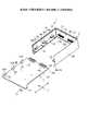
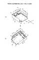
図1は、実施例1の電子機器の一部を省略した分解斜視図、図2は、実施例1の電子機器の筐体の一部を省略した斜視図である。図1に示す電子機器1は、筐体2と、筐体2内部に実装されるドーターボード3と有する。筐体2は、開口部11をなす正面部2Aと、正面部2Aに対向する背面部2Bと、背面部2Bと隣接する第1の側面部2Cと、背面部2Bと隣接し、第1の側面部2Cと対向する第2の側面部2Dと、図示せぬ上面部及び底面部とを有する。 FIG. 1 is an exploded perspective view in which a part of the electronic device according to the first embodiment is omitted, and FIG. 2 is a perspective view in which a part of the casing of the electronic device according to the first embodiment is omitted. An electronic apparatus 1 illustrated in FIG. 1 includes a
背面部2Bには、第1のバックプレーン12が配設される。第1のバックプレーン12には、第1のコネクタ13が2個配置してある。第1のコネクタ13は、その正面部に嵌合面13Aを有するストレート方式のコネクタである。第1の側面部2Cには、第2のバックプレーン14が配設される。第2のバックプレーン14には、第2のコネクタ15が3個配置してある。第2のコネクタ15は、その側面部に嵌合面15Aを有するライトアングル方式のコネクタである。 A
また、ドーターボード3の先端部3A側には、第1のバックプレーン12の第1のコネクタ13に嵌合する、ストレート方式の第3のコネクタ21が2個配置してある。また、ドーターボード3の第1の側面部3B側には、第2のバックプレーン14の第2のコネクタ15に嵌合する、ライトアングル方式の第4のコネクタ22が3個配置してある。 In addition, two straight-type
また、筐体2内部の第1の側面部2C及び第2の側面部2Dには、開口部11から挿入されたドーターボード3の下面と当接し、ドーターボード3を摺動可能に保持するガイドレール16が配設される。ガイドレール16は、第1のコネクタ13、第3のコネクタ21、第2のコネクタ15及び第4のコネクタ22を水平に配置し、背面部2B、第1の側面部2C及び第2の側面部2Dに対してドーターボード3が垂直に配置されるべくドーターボード3を保持する。 In addition, the first
更に、筐体2内部の第2の側面部2Dには、開口部11から挿入されたドーターボード3を筐体2内部に案内するガイド機構17が配設される。ガイド機構17は、ドーターボード3の側面部3Cと当接し、ガイドレール16上に保持されたドーターボード3を筐体2内部の挿入方向に案内する。尚、筐体2内部に対するドーターボード3の挿入方向をX方向とした場合、第1の側面部2Cへ向かう方向であって、X方向と直交するドーターボード3面の水平方向をY方向とする。 Further, a
ガイド機構17は、第2の側面部2Dに配設された案内溝部材30で構成される。案内溝部材30には、開口部11から挿入されたドーターボード3の第2の側面部3Cが当接しながら摺動される案内溝31が形成してある。案内溝31は、直線移動の開始位置30A、平行移動の開始位置30B、平行移動の終了位置30C及び直線移動の終了位置30Dを経て、挿入開始から実装完了までドーターボード3を案内する溝である。 The
直線移動の開始位置30Aは、ドーターボード3の摺動時に、案内溝31内でドーターボード3のX方向の直線移動を開始する位置である。平行移動の開始位置30Bは、直線移動の開始位置30Aからドーターボード3のX方向の直線移動を終了し、案内溝31内でドーターボード3の第1の側面部2C側の斜め方向への平行移動を開始する位置である。平行移動の終了位置30Cは、ドーターボード3の第1の側面部2C側の斜め方向への平行移動を終了し、案内溝31内でドーターボード3のX方向の直線移動を再開する位置である。直線移動の終了位置30Dは、案内溝31内でドーターボード3のX方向の直線移動を終了する位置である。 The linear movement start
案内溝31は、第1の案内溝31Aと、第1の案内溝31Aと連設する第2の案内溝31Bと、第2の案内溝31Bと連設する第3の案内溝31Cとを有する。第1の案内溝31Aは、直線移動の開始位置30Aと平行移動の開始位置30Bとの間でドーターボード3を案内する溝である。 The
第1の案内溝31Aは、X方向の直線移動時に、第2のコネクタ15と第4のコネクタ22とが相互に干渉しないようにドーターボード3を案内する。第2の案内溝31Bは、平行移動の開始位置30Bと平行移動の終了位置30Cとの間でドーターボード3を案内する溝である。第2の案内溝31Bは、バックプレーン12方向に摺動されるドーターボード3を、第2の側面部2Dから第1の側面部2Cに向かう方向に摺動により平行移動させる。その結果、ドーターボード3は、第2のコネクタ15の嵌合面15Aに対して、嵌合対象となる第4のコネクタ22の嵌合面22Aが対向する位置に案内されることになる。同様に、ドーターボード3は、第1のコネクタ13の嵌合面13Aに対して、嵌合対象となる第3のコネクタ21の嵌合面21Aが対向する位置に案内されることになる。 The
第3の案内溝31Cは、平行移動の終了位置30Cと直線移動の終了位置30Dとの間でドーターボード3を案内する溝である。第3の案内溝31Cは、ドーターボード3のX方向の直線移動を再開することで、第1のコネクタ15に対して第3のコネクタ21を嵌合すると共に、第2のコネクタ15に対して第4のコネクタ22を嵌合する。この様にして、ドーターボード3は、第1の案内溝31A、第2の案内溝31B及び第3の案内溝31Cにより案内されることにより、ワンストロークで第1の側面部2C及び第1のバックプレーン12と接続される。尚、平行移動の終了位置30Cから直線移動の終了位置30Dまでの距離は、少なくとも、第1のコネクタ15に対して第3のコネクタ21の嵌合開始から嵌合完了するまでの移動距離以上である。 The
また、ドーターボード3の側面部3Cには、その先端部3Dから後方の位置、例えば、直線移動の開始位置30Aから平行移動の開始位置30Bまでの距離に相当する位置に突出する突部41が形成してある。突部41は、ドーターボード3の側面部3Cの先端部3Dが第2の案内溝31B内の平行移動の開始位置30Bに到達すると、第1の案内溝31A内の直線移動の開始位置30Aに進入する。突部41は、第1の案内溝31A内の進入に応じてドーターボード3が第1の側面部2C側へ摺動により平行移動することを支援する。尚、側面部3Cの表面から突出する突部41の寸法L1は、第2の案内溝31Bでドーターボード3が第2の側面部2D側から第1の側面部2C側に平行移動する際のY方向の移動量L2に等しい(図3−1(A)参照)。 Further, on the
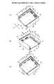
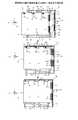
次に、実施例1の電子機器1の組立方法について説明する。図3−1、図3−2及び図4は、実施例1の電子機器1の組立工程の一例を示す説明図である。開口部11からドーターボード3が筐体2内部に挿入される。図3−1(A)に示すドーターボード3は、その側面部3Cが第1の案内溝31A内を摺動することで、筐体2内部に案内される。ドーターボード3は、第1の案内溝31Aを通じて筐体2内部のX方向に案内する。この際、ドーターボード3は、第1の側面部2C及び第2の側面部2Dに形成されたガイドレール16上に保持される。その結果、ドーターボード3は、第1のコネクタ13、第3のコネクタ21、第2のコネクタ15及び第4のコネクタ22が水平に配置された状態で、第1のバックプレーン12及び第2のバックプレーン14に対して垂直に保持される。 Next, a method for assembling the electronic device 1 according to the first embodiment will be described. 3A, 3B, and 4 are explanatory diagrams illustrating an example of an assembly process of the electronic device 1 according to the first embodiment. The
更に、図3−1(B)に示すドーターボード3は、図4(A)に示す通り、その側面部3Cの先端部3Dが第1の案内溝31Aを経て平行移動の開始位置30Bに到達するまで、ガイドレール16上をX方向に直線移動する。更に、ドーターボード3は、その側面部3Cの先端部3Dが平行移動の開始位置30Bに到達されると、後方の突部41が第1の案内溝31Aに進入する。そして、図3−1(C)に示すドーターボード3は、その側面部3Cの先端部3Dが平行移動の開始位置30Bを超えて第2の案内溝31B内に進入すると、ドーターボード3の第1の側面部2C側の斜め方向への平行移動を開始する。更に、突部41の第1の案内溝31Aへの進入に伴う第1の案内溝31Aに対する突部41の相互干渉は、第1の側面部2C側の斜め方向へのドーターボード3の平行移動が円滑に進むように、その平行移動を支援する。 Further, as shown in FIG. 4A, the
更に、図3−2(A)に示すドーターボード3は、その側面部3Cの先端部3Dが第2の案内溝31Bの平行移動の終了位置30Cに到達されると、第1の側面部2C側の斜め方向への平行移動が終了することになる。その結果、ドーターボード3は、図4(B)に示すように、第1のコネクタ13の嵌合面13Aと第3のコネクタ21の嵌合面21Aとが対向する位置、更に、第2のコネクタ15の嵌合面15Aと第4のコネクタ22の嵌合面22Aとが対向する位置に案内される。 Further, the
そして、図3−2(B)に示すドーターボード3は、X方向への直線移動に応じて、その側面部3Cの先端部3Dが第3の案内溝31Cに進入して直線移動の終了位置30Dに到達する。ドーターボード3は、図4(C)に示すように、その先端部3Dが直線移動の終了位置30Dに到達されると、第1のコネクタ13に対して第3のコネクタ21を嵌合すると共に、第2のコネクタ15に対して第4のコネクタ22を嵌合する。その結果、ドーターボード3は、ユーザによる1回の挿入操作で、第1のバックプレーン12及び第2のバックプレーン14に対して垂直に実装される。 And the
実施例1では、1回の挿入操作で案内溝31を通じて、第1のコネクタ13及び第3のコネクタ21の嵌合面13A,21A同士、第2のコネクタ15及び第4のコネクタ22の嵌合面15A,22A同士が対向する位置にドーターボード3が案内される。そして、電子機器1は、第1のコネクタ13及び第3のコネクタ21同士、第2のコネクタ15及び第4のコネクタ22同士を嵌合することで、第1のバックプレーン12及び第2のバックプレーン14に対してドーターボード3が垂直に実装されることになる。その結果、実施例1では、第1のバックプレーン12及び第2のバックプレーン14に対して垂直にドーターボード3を実装する際の作業負担を軽減できる。更に、実施例1の電子機器1では、ドーターボード3上の配線密度の偏りを防止するため、ドーターボード3の実装枚数を抑えることができる。 In the first embodiment, the
また、上記実施例1では、案内溝部材30の案内溝31を通じてドーターボード3を第1の側面部2C側の斜め方向へ平行移動させた。しかしながら、案内溝31の代わりに、案内突部を形成し、更に、ドーターボード3の側面部3Cに案内凹部を形成し、案内凹部内を案内突部が摺動してドーターボード3を第1の側面部2C側の斜め方向に平行移動させるようにしても良い。 Moreover, in the said Example 1, the
また、上記実施例1では、ガイド機構17を案内溝31や案内突部に関係なく、ドーターボード3の側面部3Cを摺動してドーターボード3を第1の側面部2C側の斜め方向に平行移動できる案内面としても良い。 In the first embodiment, the
また、上記実施例1では、案内溝31を備えた案内溝部材30を第2の側面部2Dに配設したが、第2の側面部2Dに案内溝31を直接形成するようにしても良い。 In the first embodiment, the
また、上記実施例1では、ドーターボード3の側面部3Cに形成した突部41が第1の案内溝31Aに進入して案内溝31に対する突部41の干渉動作に応じてドーターボード3の平行移動を支援するようにしたが、突部41を設けなくても良い。 Further, in the first embodiment, the
また、上記実施例1では、ガイド機構17として案内溝部材30を例に挙げて説明したが、案内溝部材30の代わりに、第2の側面部2Dに回動自在に配置された梃子部材を使用してドーターボード3を第1の側面部2C側に平行移動させるようにしても良い。そこで、この場合の実施の形態につき、実施例2として以下に説明する。 In the first embodiment, the
図5は、実施例2の電子機器1Aの一部を省略した分解斜視図である。図6は、実施例2の電子機器1Aの筐体2aの一部を省略した斜視図である。尚、実施例1の電子機器1と同一のものには同一符号を付すことで、その重複する構成及び動作の説明については省略する。 FIG. 5 is an exploded perspective view in which a part of the
図5に示す電子機器1Aと図1に示す電子機器1とが大きく異なるところは、第2の側面部2Dに配設されたガイド機構17として案内溝部材30を使用する代わりに、梃子部材50を使用した点にある。梃子部材50は、第2の側面部2Dに形成されたガイドレール16上に回動自在に配設される。梃子部材50は、基材51と、基材51の先端部に配設されたレバー部52と、基材51の後端部に配設されたガイド部53と、レバー部52及びガイド部53を回動自在にする支点54とを有する。 The
梃子部材50のガイド部53は、開口部11から挿入されたドーターボード3aの側面部3Cが摺動されながら、筐体2a内部に対してX方向にドーターボード3を案内する。尚、ドーターボード3は、第1のコネクタ13、第3のコネクタ21、第2のコネクタ15及び第4のコネクタ22が水平に配置された状態で、第1のバックプレーン12及び第2のバックプレーン14に対して垂直に配置されることになる。 The
梃子部材50のレバー部52は、開口部11から挿入されたドーターボード3aのX方向の直線移動に応じて、ドーターボード3aの側面部3Cの先端部3Dで押圧される。レバー部52は、先端部3Dの押圧動作に応じて、支点54を中心にして第2の側面部2D側に回動する。更に、梃子部材50のガイド部53は、レバー部52の第2の側面部2D側への回動に応じて支点54を中心に第1の側面部2C側に回動する。ガイド部53は、第1の側面部2C側への回動に応じて、ドーターボード3aの側面部3Cを第1の側面部2C側の斜め方向に押圧する。その結果、ガイド部53は、押圧動作に応じて第1のコネクタ13及び第3のコネクタ21の嵌合面13A,21A同士が対向する位置、第2のコネクタ15及び第4のコネクタ22の嵌合面15A,22A同士が対向する位置にドーターボード3aを平行移動する。 The
更に、梃子部材50のレバー部52は、ドーターボード3の先端部3Dの押圧動作で、ドーターボード3を第1の側面部2C側の斜め方向へ平行移動させる。レバー部52は、ドーターボード3の第1の側面部2C側の平行移動が完了するタイミングで、ドーターボード3の先端部3Dと当接しなくなる。そして、ドーターボード3aは、第1のコネクタ13及び第3のコネクタ21の嵌合面13A,21A同士、第2のコネクタ15及び第4のコネクタ22の嵌合面15A,22A同士が対向する位置から筐体2a内部のX方向に直線移動する。そして、ドーターボード3aは、第1のコネクタ13に対して第3のコネクタ21を嵌合すると共に、第2のコネクタ15に対して第4のコネクタ22を嵌合することで、第1のバックプレーン12及び第2のバックプレーン14に対して垂直に実装される。 Further, the
次に、実施例2の電子機器1Aの組立方法について説明する。図7−1、図7−2及び図8は、実施例2の電子機器1Aの組立工程の一例を示す説明図である。ユーザは、ドーターボード3aを筺体2a内部に挿入する。図7−1(A)に示すドーターボード3は、その側面部3Cを開口部11から第2の側面部2D側の梃子部材50に沿って筐体2a内部のX方向に挿入される。この際、ドーターボード3aは、筐体2a内部の第1の側面部2C及び第2の側面部2Dに形成されたガイドレール16上に保持される。その結果、ドーターボード3aは、第1のコネクタ13、第3のコネクタ21、第2のコネクタ15及び第4のコネクタ22が水平に配置された状態で、第1のバックプレーン12及び第2のバックプレーン14に対して垂直に保持されることになる。 Next, a method for assembling the
更に、図7−1(B)に示すドーターボード3aは、筐体2a内部のX方向に挿入されると、ガイドレール16上をX方向に直線移動する。そして、ドーターボード3aは、X方向の直線移動に応じて、図8(A)に示す通り、その側面部3Cの先端部3Dが梃子部材50のレバー部52を押圧する。梃子部材50のレバー部52は、ドーターボード3aの押圧動作に応じて、支点54を中心にして第2の側面部2D側に回動する。梃子部材50のガイド部53は、レバー部52の第2の側面部2D側の回動動作に連動して第1の側面部2C側に回動する。 Furthermore, when the
更に、図7−2(A)及び(B)に示すドーターボード3aは、梃子部材50のガイド部54の第1の側面部2C側への回動動作に応じて、その後端部を第1の側面部2C側の斜め方向への平行移動を開始する。梃子部材50のレバー部52は、ドーターボード3の第1の側面部2C側の平行移動が完了するタイミングで、ドーターボード3aの先端部3Dと当接しなくなる。レバー部52は、ドーターボード3の先端部3Dと当接しなくなると、第2の側面部2D側への回動動作を停止する。レバー部52は、第2の側面部2D側への回動動作を停止すると、ガイド部54の第1の側面部2C側への回動動作も停止する。その結果、ドーターボード3aは、図8(B)に示すように第1のコネクタ13の嵌合面13Aと第3のコネクタ21の嵌合面21Aとが対向する位置、更に、第2のコネクタ15の嵌合面15Aと第4のコネクタ22の嵌合面22Aとが対向する位置に案内される。 Further, in the
そして、図7−2(C)に示すドーターボード3aは、ガイド部54の第1の側面部2C側への回動動作が停止したまま、X方向に直線移動する。ドーターボード3aは、図8(C)に示すように、第1のコネクタ13に対して第3のコネクタ21が嵌合すると共に、第2のコネクタ15に対して第4のコネクタ22が嵌合する。その結果、ドーターボード3aは、第1のバックプレーン12及び第2のバックプレーン14に対して垂直に実装されることになる。 And the
実施例2では、1回の挿入操作による、ドーターボード3aの先端部3DのX方向の直線移動に応じて、梃子部材50のレバー部52が第2の側面部2D側へ回動する。更に、梃子部材50のガイド部54は、レバー部52の回動動作に連動して第1の側面部2C側へ回動する。ガイド部54は、第1の側面部2C側への回動動作に応じてドーターボード3aを第1の側面部2C側の斜め方向に平行移動させる。そして、ドーターボード3aは、第1のコネクタ13及び第3のコネクタ21の嵌合面13A,21A同士、第2のコネクタ15及び第4のコネクタ22の嵌合面15A,22A同士が対向する位置に案内される。そして、電子機器1Aは、第1のコネクタ13及び第3のコネクタ21同士、第2のコネクタ15及び第4のコネクタ22同士が嵌合することで、第1のバックプレーン12及び第2のバックプレーン14に対してドーターボード3aが垂直に実装される。その結果、実施例2では、第1のバックプレーン12及び第2のバックプレーン14に対して垂直にドーターボード3を実装する際の作業負担を軽減できる。 In the second embodiment, the
尚、上記実施例1及び2では、第1のバックプレーン12及び第2のバックプレーン14を筐体2a内部の背面部2B及び第1の側面部2Cに配設した。しかしながら、例えば、背面部2B及び第2の側面部2D、上面部及び第1の側面部2C、上面部及び第2の側面部2D、底面部及び第1の側面部2Cや、底面部及び第2の側面部2D等に2枚のバックプレーンを配設しても良い。 In the first and second embodiments, the
また、上記実施例1及び2では、第1のバックプレーン12及び第2のバックプレーン14に対して一枚のドーターボード3,3aを垂直に実装したが、これらバックプレーンに対して複数枚のドーターボード3,3aを実装しても同様の効果が得られる。図9は、複数枚のドーターボード3を実装した電子機器1Bの一部を省略した分解斜視図である。電子機器の筐体内に複数枚のドーターボード3aを実装する場合も同様である。尚、説明の便宜上、図1に示す電子機器1と同一の構成には同一符号を付すことで、その重複する構成及び動作の説明については省略する。また、説明の便宜上、上面部及び底面部は勿論のこと、第2の側面部2D及びガイド機構17の図示を省略した。図9に示す電子機器1Bでは、図示せぬガイド機構17を使用して、第1のバックプレーン12及び第2のバックプレーン14に対してドーターボード3を垂直に順次実装する。そして、電子機器1Bでは、第1のバックプレーン12及び第2のバックプレーン14に対して複数枚のドーターボード3を簡単に実装することができる。更に、ドーターボード3間を電気的に接続する場合には、ドーターボード3間をジャンパー線61で電気的に接続しても良い。 In the first and second embodiments, a
また、上記実施例では、ドーターボード3,3aが筐体2,2a内部に挿入されると、第2のコネクタ15及び第4のコネクタ22の相互干渉を回避しながらドーターボード3,3aをX方向に直線移動させ、更に第1の側面部2C側の斜め方向に平行移動させる。更に、平行移動されたドーターボード3,3aをX方向に直線移動させる。その結果、ドーターボード3,3aは、第1のコネクタ13及び第3のコネクタ21同士、第2のコネクタ15及び第4のコネクタ22同士を同時に嵌合する。つまり、上記実施例では、ドーターボード3の面部に対して垂直方向にドーターボード3を移動してコネクタ同士を嵌合する従来の構造に比べて、コネクタ同士の嵌合に際して、垂直方向にドーターボード3を移動させる作業スペースが不要となる。その結果、上記実施例では、作業スペースが不要になるため、ドーターボード3,3aが実装される層間の間隔を短くして電子機器の小型化を図ることができる。 In the above embodiment, when the
また、上記実施例1及び2では、第1のバックプレーン12及び第2のバックプレーン14に対して垂直にドーターボード3,3aを実装するので、第1のバックプレーン12の背面部2Bに対してドーターボード3,3aのコネクタの集中配置を回避できる。従って、開口部11と対向する背面部2B側の第1のバックプレーン12に実装するコネクタの数を減らし、背面部2Bに通気口を配置するスペースを確保できる。その結果、開口部11から背面部2Bの通気口に冷却風が一定の方向、すなわちX方向に流れるため、冷却効率の向上を図ることができる。 In the first and second embodiments, since the
以上、本実施例を含む実施の形態に関し、更に以下の付記を開示する。 As described above, the following supplementary notes are further disclosed regarding the embodiment including the present example.
(付記1)1面に開口を有する直方体状の筐体と、
前記筐体の開口に対向する背面に配設される第1のバックプレーンと、
前記筐体に配設され、前記背面と隣接する面に配置される第2のバックプレーンと、
前記第1のバックプレーンに向けて前記筐体の開口から挿入されて前記第1のバックプレーンおよび前記第2のバックプレーンにコネクタを介して接続される回路基板と、
前記筐体の、前記第2のバックプレーンに対向して配置され、前記回路基板を案内するガイド機構と、
前記第1のバックプレーンおよび前記第2のバックプレーンにコネクタを介して接続される回路基板と、を備え、
前記ガイド機構は、前記回路基板の角部が当接されることで、前記回路基板を前記第2のバックプレーン側へ摺動させることを特徴とする電子装置。(Supplementary note 1) a rectangular parallelepiped housing having an opening on one surface;
A first backplane disposed on a back surface facing the opening of the housing;
A second backplane disposed on the housing and disposed on a surface adjacent to the back surface;
A circuit board inserted through an opening of the housing toward the first backplane and connected to the first backplane and the second backplane via a connector;
A guide mechanism that is disposed opposite to the second backplane of the housing and guides the circuit board;
A circuit board connected to the first backplane and the second backplane via a connector,
The electronic device according to claim 1, wherein the guide mechanism slides the circuit board toward the second backplane side by contacting a corner portion of the circuit board.
(付記2)前記ガイド機構は、前記回路基板の角部が当接される部分が前記第2のバックプレーンに向けて斜めに形成されることを特徴とする付記1に記載の電子装置。(Supplementary note 2) The electronic device according to supplementary note 1, wherein the guide mechanism is formed such that a portion with which a corner portion of the circuit board abuts is formed obliquely toward the second backplane.
(付記3)前記第2のバックプレーンには、複数のコネクタが前記回路基板の挿入方向に対応して配列され、
前記回路基板の前記第2のバックプレーンに対向する端部側には、前記第2のバックプレーンの複数のコネクタに接続される複数のコネクタが設けられており、前記ガイド機構に沿った前記回路基板の摺動により前記第2のバックプレーンの複数のコネクタの間に導入されることを特徴とする付記1または2に記載の電子装置。(Additional remark 3) A plurality of connectors are arranged on the second backplane corresponding to the insertion direction of the circuit board,
A plurality of connectors connected to a plurality of connectors of the second backplane are provided on an end portion side of the circuit board facing the second backplane, and the circuit along the guide mechanism is provided. The electronic device according to
(付記4)前記回路基板は、前記角部が前記ガイド機構に当接される際に併せて前記筐体に当接する凸部を備えることを特徴とする付記1から3のいずれか一つに記載の電子装置。(Additional remark 4) The said circuit board is provided with the convex part which contact | abuts to the said housing | casing in addition, when the said corner | angular part contact | abuts to the said guide mechanism. The electronic device described.
(付記5)前記ガイド機構は、前記筐体に回動自在に支持されて前記回路基板の角部が一端部に当接されたときに、他端部が前記回路基板を前記第2のバックプレーン側へ摺動させることを特徴とする付記1から3のいずれか一つに記載の電子装置。(Supplementary Note 5) When the guide mechanism is rotatably supported by the casing and the corner portion of the circuit board is brought into contact with one end portion, the other end portion causes the circuit board to move to the second back. The electronic device according to any one of appendices 1 to 3, wherein the electronic device is slid to a plane side.
(付記6)一面に開口を有する筐体の背面に配設される第1のバックプレーンに向けて回路基板がガイド機構に沿って案内され、前記背面に隣接する面に配設される第2のバックプレーンとコネクタを介して接続される回路基板の接続構造において、
前記回路基板の角部が前記ガイド機構に当接すると、前記回路基板を前記第2のバックプレーン側へ摺動させることを特徴とする回路基板の接続構造。(Appendix 6) A circuit board is guided along a guide mechanism toward a first backplane disposed on the back surface of a housing having an opening on one surface, and is disposed on a surface adjacent to the back surface. In the circuit board connection structure that is connected to the backplane via the connector,
A circuit board connection structure, wherein the circuit board is slid toward the second backplane when a corner portion of the circuit board contacts the guide mechanism.
(付記7)一つの面に開口部を有する筐体と、
前記開口部に対向する前記筐体内部の第1の面に配設され、前記開口部に対向する嵌合面を有する第1のコネクタを備えた第1のバックプレーンと、
前記第1の面と隣接する前記筐体内部の第2の面に配設され、前記開口部に対向する嵌合面を有する第2のコネクタを備えた第2のバックプレーンと、
前記第1のバックプレーン及び前記第2のバックプレーンに対して垂直に配置され、前記第1のコネクタに嵌合する第3のコネクタ及び、前記第2のコネクタに嵌合する第4のコネクタを備えた基板と、
前記第2の面に対向する第3の面に配設され、前記開口部から前記第1の面の方向に挿入される前記基板に当接されることで、前記開口部から前記第1の面の方向に移動する前記基板を、前記第3の面から前記第2の面の方向に摺動させるガイド機構と
を有することを特徴とする電子機器。(Appendix 7) a housing having an opening on one surface;
A first backplane provided with a first connector disposed on a first surface inside the housing facing the opening and having a fitting surface facing the opening;
A second backplane provided with a second connector disposed on a second surface inside the housing adjacent to the first surface and having a fitting surface facing the opening;
A third connector that is arranged perpendicular to the first backplane and the second backplane and that fits into the first connector; and a fourth connector that fits into the second connector. A board with
The first surface is disposed on the third surface opposite to the second surface and is in contact with the substrate inserted from the opening toward the first surface. An electronic apparatus comprising: a guide mechanism that slides the substrate moving in the direction of a surface from the third surface in the direction of the second surface.
(付記8)前記ガイド機構は、
前記開口部から前記第1の面の方向に延在し、前記第3の面と対向する前記基板の端面を摺動し、前記基板を直線移動させる第1の案内面と、
前記第1の案内面から前記第2の面側の方向に延在し、前記基板の端面を摺動し、前記第3の面から前記第2の面の方向へ前記基板を斜めに平行移動させる第2の案内面と、
前記第2の案内面から前記第1の面の方向に延在し、前記基板の端面を摺動し、前記基板を直線移動させる第3の案内面と
を有することを特徴とする付記7に記載の電子機器。(Appendix 8) The guide mechanism is
A first guide surface extending from the opening in the direction of the first surface, sliding on an end surface of the substrate facing the third surface, and linearly moving the substrate;
The substrate extends from the first guide surface toward the second surface, slides on the end surface of the substrate, and moves the substrate obliquely in parallel from the third surface toward the second surface. A second guide surface to be
Appendix 7 characterized by having a third guide surface extending from the second guide surface in the direction of the first surface, sliding on the end surface of the substrate, and linearly moving the substrate. The electronic device described.
(付記9)前記ガイド機構は、
前記第3の面側に回動自在に配設された梃子部材を有し、
前記挿入方向への前記基板の直線移動に応じて前記梃子部材の先端部が回動し、当該梃子部材の梃子動作に応じて当該梃子部材の後端部が前記第2の面側の方向に回動し、当該後端部の回動動作に応じて前記基板を前記第3の面から前記第2の面の方向へ斜めに平行移動させることを特徴とする付記7に記載の電子機器。(Appendix 9) The guide mechanism is
A lever member rotatably disposed on the third surface side;
The front end portion of the lever member rotates in accordance with the linear movement of the substrate in the insertion direction, and the rear end portion of the lever member in the direction of the second surface side in response to the lever operation of the lever member. The electronic device according to appendix 7, wherein the electronic device rotates and obliquely translates the substrate from the third surface toward the second surface in accordance with a rotation operation of the rear end portion.
(付記10)前記ガイド機構は、
前記第2のコネクタの嵌合面と、当該第2のコネクタの嵌合対象である前記第4のコネクタの嵌合面とが対向する位置に、前記基板を前記第3の面から前記第2の面の方向へ斜めに平行移動させることを特徴とする付記7〜9の何れか一つに記載の電子機器。(Appendix 10) The guide mechanism is
The board is moved from the third surface to the second surface at a position where the fitting surface of the second connector and the fitting surface of the fourth connector to be fitted to the second connector face each other. The electronic device according to any one of appendices 7 to 9, wherein the electronic device is obliquely translated in the direction of the surface.
(付記11)前記第1の案内面、前記第2の案内面及び前記第3の案内面を摺動する前記基板の端面に、その先端から後方へ、前記第1の案内面の摺動距離分に相当する位置に前記第3の面側の方向に突出する突部を形成し、
前記突部は、
前記第1の案内面との当接に応じて、前記第3の面から前記第2の面の方向への前記基板の平行移動を支援することを特徴とする付記8に記載の電子機器。(Additional remark 11) The sliding distance of the said 1st guide surface to the end surface of the said board | substrate which slides on the said 1st guide surface, the said 2nd guide surface, and the said 3rd guide surface from the front-end | tip back Forming a protrusion projecting in the direction of the third surface at a position corresponding to the minute;
The protrusion is
The electronic apparatus according to appendix 8, wherein the electronic device supports parallel movement of the substrate from the third surface to the second surface in response to contact with the first guide surface.
(付記12)前記第1の面及び前記第2の面には、
前記筐体内部に前記基板を挿入し、前記基板が前記第1のバックプレーン及び第2のバックプレーンに対して垂直に配置されるべく、当該基板を保持するガイドレールを配設したことを特徴とする付記7〜11の何れか一つに記載の電子機器。(Supplementary Note 12) The first surface and the second surface include
The board is inserted into the housing, and a guide rail for holding the board is arranged so that the board is arranged perpendicular to the first backplane and the second backplane. The electronic device according to any one of appendices 7 to 11.
(付記13)前記第1の案内面、前記第2の案内面及び前記第3の案内面には、
前記基板の端面を案内する溝が形成してあることを特徴とする付記8に記載の電子機器。(Supplementary Note 13) The first guide surface, the second guide surface, and the third guide surface include
9. The electronic device according to appendix 8, wherein a groove for guiding the end face of the substrate is formed.
(付記14)前記第1のコネクタ及び前記第3のコネクタは、
前記第1のコネクタの正面部及び前記第3のコネクタの正面部に嵌合面を配置したストレート方式のコネクタに相当すると共に、
前記第2のコネクタ及び前記第4のコネクタは、
前記第2のコネクタの側面部及び前記第4の側面部に嵌合面を配置したライトアングル方式のコネクタに相当することを特徴とする付記7〜13の何れか一つに記載の電子機器。(Supplementary Note 14) The first connector and the third connector are
While corresponding to a straight connector having a fitting surface disposed on the front portion of the first connector and the front portion of the third connector,
The second connector and the fourth connector are:
The electronic apparatus according to any one of appendices 7 to 13, which corresponds to a right angle type connector in which fitting surfaces are arranged on a side surface portion of the second connector and the fourth side surface portion.
(付記15)前記ガイド機構は、
前記開口部から前記基板の前記第1の面の方向への直線移動時に、前記第2のコネクタ及び前記第4のコネクタ同士が干渉しない状態で、前記基板を直線移動させることを特徴とする付記7〜14の何れか一つに記載の電子機器。(Supplementary Note 15) The guide mechanism is
The substrate is linearly moved in a state in which the second connector and the fourth connector do not interfere with each other when the substrate is linearly moved from the opening toward the first surface. The electronic device according to any one of 7 to 14.
(付記16)前記ガイド機構にて前記平行移動された前記基板を前記挿入方向に直線移動させる際の前記基板の直線移動距離は、少なくとも、前記第1のコネクタの嵌合対象である前記第3
のコネクタが前記第1のコネクタに対して嵌合開始から嵌合完了するまでの前記基板の移動距離以上であることを特徴とする付記7〜15の何れか一つに記載の電子機器。(Supplementary Note 16) The linear movement distance of the board when the board translated by the guide mechanism is linearly moved in the insertion direction is at least the third connector to be fitted to the first connector.
The electronic device according to any one of appendices 7 to 15, wherein the connector is equal to or longer than a moving distance of the board from the start of fitting to the completion of fitting to the first connector.
(付記17)筐体の開口部に対向する第1の面に配設され、前記開口部に対向する嵌合面を有する第1のコネクタを備えた第1のバックプレーン及び、前記第1の面と隣接する第2の面に配設され、前記開口部に対向する嵌合面を有する第2のコネクタを備えた第2のバックプレーンに対して、前記第1のコネクタに嵌合する第3のコネクタ及び、前記第2のコネクタに嵌合する第4のコネクタを備えた基板を垂直に実装する基板実装構造であって、
前記基板を前記筐体内に案内させるガイド機構に、前記開口部から前記第1の面の方向に挿入される前記基板に当接されることで、前記開口部から前記第1の面の方向に移動する前記基板を、前記第3の面から前記第2の面の方向に摺動させることを特徴とする基板実装構造。(Supplementary Note 17) A first backplane provided with a first connector disposed on a first surface facing the opening of the housing and having a fitting surface facing the opening, and the first A second backplane provided with a second connector disposed on a second surface adjacent to the surface and having a fitting surface facing the opening, and is fitted to the first connector. 3 and a board mounting structure for vertically mounting a board provided with a fourth connector fitted to the second connector,
The guide mechanism that guides the substrate into the housing is brought into contact with the substrate that is inserted in the direction of the first surface from the opening portion, so that the opening portion moves in the direction of the first surface. A substrate mounting structure, wherein the moving substrate is slid in the direction from the third surface to the second surface.
1 電子機器
1A 電子機器
1B 電子機器
2 筐体
2a 筐体
2B 背面部
2C 第1の側面部
2D 第2の側面部
3 ドーターボード
3a ドーターボード
11 開口部
12 第1のバックプレーン
13 第1のコネクタ
13A 嵌合面
14 第2のバックプレーン
15 第2のコネクタ
15A 嵌合面
17 ガイド機構
31 案内溝
31A 第1の案内溝
31B 第2の案内溝
31C 第3の案内溝
21 第3のコネクタ
21A 嵌合面
22 第4のコネクタ
22A 嵌合面
41 突部
50 梃子部材
52 レバー部
53 ガイド部DESCRIPTION OF SYMBOLS 1
Claims (7)
Translated fromJapanese前記筐体の開口に対向する背面に配設される第1のバックプレーンと、
前記筐体に配設され、前記背面と隣接する面に配置される第2のバックプレーンと、
前記第1のバックプレーンに向けて前記筐体の開口から挿入されて前記第1のバックプレーンおよび前記第2のバックプレーンにコネクタを介して接続される回路基板と、
前記筐体の、前記第2のバックプレーンに対向して配置され、前記回路基板を案内するガイド機構と
を備え、
前記第2のバックプレーンには、複数のコネクタが前記回路基板の挿入方向に対応して配列され、前記回路基板の前記第2のバックプレーンに対向する端部側には、前記第2のバックプレーンの複数のコネクタに接続されるコネクタが設けられており、
前記ガイド機構は、前記回路基板の角部が当接されることで、前記回路基板を前記第2のバックプレーン側へ摺動させ、前記第2のバックプレーンの複数のコネクタの間に前記回路基板が導入されることを特徴とする電子装置。A rectangular parallelepiped housing having an opening on one surface;
A first backplane disposed on a back surface facing the opening of the housing;
A second backplane disposed on the housing and disposed on a surface adjacent to the back surface;
A circuit board inserted through an opening of the housing toward the first backplane and connected to the first backplane and the second backplane via a connector;
A guide mechanism that is disposed to face the second backplane of the housing and guides the circuit board;
On the second backplane, a plurality of connectors are arranged corresponding to the insertion direction of the circuit board, and the second backplane has an end portion facing the second backplane on the second backplane. There are connectors that connect to multiple connectors on the plane,
The guide mechanism causes the circuit board to slide toward the second backplane side by contacting a corner portion of the circuit board, and the circuit between the plurality of connectors of the second backplane. An electronic device in which a substrate is introduced.
前記筐体の開口に対向する背面に配設される第1のバックプレーンと、
前記筐体に配設され、前記背面と隣接する面に配置される第2のバックプレーンと、
前記第1のバックプレーンに向けて前記筐体の開口から挿入されて前記第1のバックプレーンおよび前記第2のバックプレーンにコネクタを介して接続される回路基板と、
前記筐体の、前記第2のバックプレーンに対向して配置され、前記回路基板を案内するガイド機構と
を備え、
前記ガイド機構は、前記筐体に回動自在に支持されて前記回路基板の角部が一端部に当接されたときに、他端部が前記回路基板を前記第2のバックプレーン側へ摺動させることを特徴とする電子装置。A rectangular parallelepiped housing having an opening on one surface;
A first backplane disposed on a back surface facing the opening of the housing;
A second backplane disposed on the housing and disposed on a surface adjacent to the back surface;
A circuit board inserted through an opening of the housing toward the first backplane and connected to the first backplane and the second backplane via a connector;
A guide mechanism that is disposed to face the second backplane of the housing and guides the circuit board;
The guide mechanism is rotatably supported by the casing, and when the corner portion of the circuit board comes into contact with one end portion, the other end portion slides the circuit board toward the second backplane side. An electronic device characterized by being moved.
前記第2のバックプレーンには、複数のコネクタが前記回路基板の挿入方向に対応して配列され、前記回路基板の前記第2のバックプレーンに対向する端部側には、前記第2のバックプレーンの複数のコネクタに接続されるコネクタが設けられており、
前記回路基板の角部が前記ガイド機構に当接すると、前記回路基板を前記第2のバックプレーン側へ摺動させ、前記第2のバックプレーンの複数のコネクタの間に前記回路基板が導入されることを特徴とする回路基板の接続構造。A circuit board is guided along a guide mechanism toward a first backplane disposed on the back surface of the housing having an opening on one side,and connected to the first backplane via a connector. In the connection structure of the circuit board connected via the connector with the second backplanedisposed on the surfaceorthogonal to the back surface,
On the second backplane, a plurality of connectors are arranged corresponding to the insertion direction of the circuit board, and the second backplane has an end portion facing the second backplane on the second backplane. There are connectors that connect to multiple connectors on the plane,
When the corner portion of the circuit board comes into contact with the guide mechanism, the circuit board is slid toward the second backplane, and the circuit board is introduced between the plurality of connectors of the second backplane. A circuit board connection structure.
前記ガイド機構が、前記筐体に回動自在に支持されて前記回路基板の角部が一端部に当接されたときに、他端部が前記回路基板を前記第2のバックプレーン側へ摺動させることを特徴とする回路基板の接続構造。A circuit board is guided along a guide mechanism toward a first backplane disposed on the back surface of the housing having an opening on one side,and connected to the first backplane via a connector. In the connection structure of the circuit board connected via the connector with the second backplanedisposed on the surfaceorthogonal to the back surface,
When the guide mechanism is rotatably supported by the housing and the corner portion of the circuit board is brought into contact with one end portion, the other end portion slides the circuit board toward the second backplane side. A circuit board connection structure characterized by being moved.
Priority Applications (3)
| Application Number | Priority Date | Filing Date | Title |
|---|---|---|---|
| JP2011057108AJP5655648B2 (en) | 2011-03-15 | 2011-03-15 | Electronic device and circuit board connection structure |
| US13/419,064US9019711B2 (en) | 2011-03-15 | 2012-03-13 | Electronic device and connection structure for circuit board |
| EP20120159435EP2500988A3 (en) | 2011-03-15 | 2012-03-14 | Electronic device and connection structure for circuit board |
Applications Claiming Priority (1)
| Application Number | Priority Date | Filing Date | Title |
|---|---|---|---|
| JP2011057108AJP5655648B2 (en) | 2011-03-15 | 2011-03-15 | Electronic device and circuit board connection structure |
Publications (2)
| Publication Number | Publication Date |
|---|---|
| JP2012195387A JP2012195387A (en) | 2012-10-11 |
| JP5655648B2true JP5655648B2 (en) | 2015-01-21 |
Family
ID=45936755
Family Applications (1)
| Application Number | Title | Priority Date | Filing Date |
|---|---|---|---|
| JP2011057108AExpired - Fee RelatedJP5655648B2 (en) | 2011-03-15 | 2011-03-15 | Electronic device and circuit board connection structure |
Country Status (3)
| Country | Link |
|---|---|
| US (1) | US9019711B2 (en) |
| EP (1) | EP2500988A3 (en) |
| JP (1) | JP5655648B2 (en) |
Families Citing this family (32)
| Publication number | Priority date | Publication date | Assignee | Title |
|---|---|---|---|---|
| US9136621B1 (en)* | 2012-08-14 | 2015-09-15 | Ciena Corporation | Guides and tab arrangement to retain a card having an edge connector and method of use |
| JP6229361B2 (en)* | 2013-08-01 | 2017-11-15 | 富士通株式会社 | Electronic equipment and board unit |
| CN105578826B (en)* | 2016-01-11 | 2018-07-17 | 岑浩明 | It is a kind of with LED light can automatic plug circuit board communication apparatus |
| CN105451501B (en)* | 2016-01-11 | 2018-04-17 | 戎佰腾 | It is a kind of with roller and can automatic plug circuit board communication apparatus |
| CN105578827B (en)* | 2016-01-11 | 2018-07-17 | 俞岳田 | It is a kind of radiate and can automatic plug circuit board communication apparatus |
| CN105578828B (en)* | 2016-01-11 | 2018-07-17 | 俞岳田 | It is a kind of can automatic plug circuit board communication apparatus |
| CN105611778B (en)* | 2016-01-11 | 2018-05-25 | 泉州市港生利来进出口贸易有限公司 | A kind of communication apparatus that there is circuit board automatic plug and can prompt |
| CN105611777B (en)* | 2016-01-11 | 2018-06-22 | 温岭市海玛进出口有限公司 | It is a kind of that there is circuit board automatic plug and the communication apparatus with idler wheel |
| CN105430995B (en)* | 2016-01-11 | 2018-07-17 | 俞岳田 | It is a kind of can it is shockproof and can automatic plug circuit board communication apparatus |
| CN105658013B (en)* | 2016-01-11 | 2018-07-17 | 岑浩明 | It is a kind of can damping and can automatic plug circuit board communication apparatus |
| CN105592658B (en)* | 2016-01-11 | 2018-06-19 | 安溪县百家宜家居用品有限公司 | It is a kind of have the function of circuit board automatic plug and can rapid cooling communication apparatus |
| CN105430994B (en)* | 2016-01-11 | 2018-04-17 | 戎佰腾 | It is a kind of be provided with electronic controller and can automatic plug circuit board communication apparatus |
| AT517707B1 (en)* | 2016-01-29 | 2017-04-15 | Avl List Gmbh | Drive and control device for a flow meter |
| WO2018022096A1 (en)* | 2016-07-29 | 2018-02-01 | Hewlett-Packard Development Company, L.P. | Electronic card holders |
| JP6631581B2 (en)* | 2017-04-17 | 2020-01-15 | 株式会社デンソー | Electronic equipment |
| US10694635B1 (en)* | 2018-08-14 | 2020-06-23 | Amazon Technologies, Inc. | Mesh network topology based on midplane board |
| JP7201424B2 (en)* | 2018-12-25 | 2023-01-10 | ファナック株式会社 | electronic device |
| US11143682B2 (en) | 2019-07-19 | 2021-10-12 | Dell Products L.P. | System and method for communicating externally from an electromagnetic interference suppressed volume |
| US10917996B1 (en) | 2019-07-19 | 2021-02-09 | Dell Products L.P. | System and method for device level thermal management and electromagnetic interference management |
| US11399450B2 (en) | 2019-07-19 | 2022-07-26 | Dell Products L.P. | System and method for managing electromagnetic interference |
| US11129307B2 (en) | 2019-07-19 | 2021-09-21 | Dell Products L.P. | System and method for managing thermal states of devices |
| US11122718B2 (en) | 2019-07-19 | 2021-09-14 | Dell Products L.P. | System and method for device level electromagnetic interference management |
| US12004336B2 (en) | 2019-07-19 | 2024-06-04 | Dell Products L.P. | System and method for thermal management and electromagnetic interference management |
| US10980159B2 (en) | 2019-07-19 | 2021-04-13 | Dell Products L.P. | System and method for managing multiple connections |
| US11644425B2 (en) | 2019-07-19 | 2023-05-09 | Dell Products L.P. | System and method for optical state determination |
| US11378608B2 (en) | 2019-07-19 | 2022-07-05 | Dell Products L.P. | System and method for device state determination |
| US11132038B2 (en) | 2019-07-19 | 2021-09-28 | Dell Products L.P. | System and method for thermal management of shadowed devices |
| US11234347B2 (en)* | 2019-07-19 | 2022-01-25 | Dell Products L.P. | System and method for physical management of devices |
| US11147194B2 (en) | 2019-08-21 | 2021-10-12 | Dell Products L.P. | System and method for managing electromagnetic interference |
| US11234350B2 (en) | 2019-08-21 | 2022-01-25 | Dell Products L.P. | System and method for isolated device access |
| TWI719603B (en)* | 2019-08-23 | 2021-02-21 | 緯創資通股份有限公司 | Connecting module and electronic device |
| CN216412150U (en)* | 2021-08-11 | 2022-04-29 | 富联精密电子(天津)有限公司 | OCP switching device, OCP integrated circuit board and PCIe integrated circuit board compatible bracket assembly and server |
Family Cites Families (24)
| Publication number | Priority date | Publication date | Assignee | Title |
|---|---|---|---|---|
| JPS50105553U (en)* | 1974-02-06 | 1975-08-30 | ||
| JPS50119282A (en) | 1974-03-08 | 1975-09-18 | ||
| US6457647B1 (en)* | 1993-11-16 | 2002-10-01 | Canon Kabushiki Kaisha | Memory card adaptor to facilitate upgrades and the like |
| US5559317A (en)* | 1995-03-27 | 1996-09-24 | International Verifact Inc. | Card reader with carriage powered by movement of inserted card |
| US5644470A (en) | 1995-11-02 | 1997-07-01 | International Business Machines Corporation | Autodocking hardware for installing and/or removing adapter cards without opening the computer system cover |
| JPH1117367A (en)* | 1997-06-26 | 1999-01-22 | Fujitsu I Network Syst Ltd | Package-mounting method |
| JP3288277B2 (en)* | 1997-09-16 | 2002-06-04 | アルプス電気株式会社 | IC card connector |
| GB9807989D0 (en) | 1998-04-16 | 1998-06-17 | Babin Andre | Extension card insertion and removal system |
| JP3806271B2 (en)* | 1999-07-09 | 2006-08-09 | 日本電産サンキョー株式会社 | Magnetic card transaction device |
| JP3635625B2 (en)* | 1999-11-05 | 2005-04-06 | 山一電機株式会社 | Card connector switch structure |
| JP3338415B2 (en)* | 1999-12-28 | 2002-10-28 | 山一電機株式会社 | Card connector |
| EP1295364A2 (en)* | 2000-06-29 | 2003-03-26 | Molex Incorporated | Ic card connector |
| JP2002223085A (en)* | 2001-01-25 | 2002-08-09 | Hitachi Ltd | Connection structure between printed circuit board and backboard, and board-to-board connector mounted on printed circuit board and backboard |
| US20030033463A1 (en)* | 2001-08-10 | 2003-02-13 | Garnett Paul J. | Computer system storage |
| DE10203066A1 (en)* | 2002-01-28 | 2003-08-07 | Marconi Comm Gmbh | Printed circuit board assembly system and method for positioning printed circuit boards |
| JP2004031806A (en)* | 2002-06-27 | 2004-01-29 | Fujitsu Ltd | Electronic circuit unit insertion / extraction mechanism |
| US6940727B2 (en)* | 2003-10-08 | 2005-09-06 | Hewlett-Packard Development Company, L.P. | Card guide that comprises card guide portions that serve to guide a circuit board into a chassis |
| JP2006024761A (en)* | 2004-07-08 | 2006-01-26 | Matsushita Electric Ind Co Ltd | Wireless base station unit slide structure |
| JP2006164627A (en) | 2004-12-03 | 2006-06-22 | Fujitsu Ltd | Connector, printed wiring board mounting apparatus, and printed wiring board mounting method |
| JP4711194B2 (en) | 2006-03-14 | 2011-06-29 | 日本電気株式会社 | Circuit board device and connector insertion / extraction method |
| KR101348247B1 (en)* | 2007-06-07 | 2014-01-09 | 삼성디스플레이 주식회사 | Liquid crystal display device |
| JP2010067192A (en)* | 2008-09-12 | 2010-03-25 | Fujitsu Ltd | Electronic apparatus |
| JP5245923B2 (en) | 2009-03-05 | 2013-07-24 | 富士通株式会社 | Electronic device system and board insertion / extraction jig |
| US8199511B2 (en)* | 2009-04-01 | 2012-06-12 | Fusion-Io, Inc. | Hot swappable computer card carrier |
- 2011
- 2011-03-15JPJP2011057108Apatent/JP5655648B2/ennot_activeExpired - Fee Related
- 2012
- 2012-03-13USUS13/419,064patent/US9019711B2/ennot_activeExpired - Fee Related
- 2012-03-14EPEP20120159435patent/EP2500988A3/ennot_activeWithdrawn
Also Published As
| Publication number | Publication date |
|---|---|
| JP2012195387A (en) | 2012-10-11 |
| US20120236521A1 (en) | 2012-09-20 |
| US9019711B2 (en) | 2015-04-28 |
| EP2500988A2 (en) | 2012-09-19 |
| EP2500988A3 (en) | 2015-03-04 |
Similar Documents
| Publication | Publication Date | Title |
|---|---|---|
| JP5655648B2 (en) | Electronic device and circuit board connection structure | |
| JP4776483B2 (en) | Connector mounting structure | |
| JP5197294B2 (en) | Board to board connector | |
| JP5660756B2 (en) | Board to board connector | |
| JP4651592B2 (en) | PIU insertion / extraction mechanism for electronic devices | |
| JP5653281B2 (en) | Module socket | |
| JP2010267411A (en) | Flexible cable connecting structure, and connector for flexible cable | |
| US20130084739A1 (en) | Coaxial connector | |
| JP2016035993A (en) | Receptacle assembly and module assembly | |
| US8449322B2 (en) | Electrical connector | |
| KR101452626B1 (en) | Connector assembly for perpendicularly connecting two substrates | |
| KR102395645B1 (en) | Contact for Substrate Connector and Substrate Connector | |
| JP2009086256A (en) | Hybrid connector | |
| JP2009086258A (en) | Plug | |
| TW201832420A (en) | Mechanism, methods, system and assembly of the same | |
| KR20130032518A (en) | An electric connector for flexible printed cirecuit | |
| JP4371836B2 (en) | Device for connecting electronic units | |
| JP5842571B2 (en) | Electrical connector | |
| JP2009086227A (en) | Hybrid connector | |
| JP6386296B2 (en) | Information processing device | |
| TWI493813B (en) | Connector | |
| JP5655675B2 (en) | Electronics | |
| KR102185663B1 (en) | Cable Connector | |
| JP2025012509A (en) | Module mounting device and information processing device | |
| TWI384934B (en) | Electronic device |
Legal Events
| Date | Code | Title | Description |
|---|---|---|---|
| A621 | Written request for application examination | Free format text:JAPANESE INTERMEDIATE CODE: A621 Effective date:20131129 | |
| A977 | Report on retrieval | Free format text:JAPANESE INTERMEDIATE CODE: A971007 Effective date:20140508 | |
| A131 | Notification of reasons for refusal | Free format text:JAPANESE INTERMEDIATE CODE: A131 Effective date:20140520 | |
| A521 | Request for written amendment filed | Free format text:JAPANESE INTERMEDIATE CODE: A523 Effective date:20140613 | |
| A131 | Notification of reasons for refusal | Free format text:JAPANESE INTERMEDIATE CODE: A131 Effective date:20140916 | |
| A521 | Request for written amendment filed | Free format text:JAPANESE INTERMEDIATE CODE: A523 Effective date:20141010 | |
| TRDD | Decision of grant or rejection written | ||
| A01 | Written decision to grant a patent or to grant a registration (utility model) | Free format text:JAPANESE INTERMEDIATE CODE: A01 Effective date:20141028 | |
| A61 | First payment of annual fees (during grant procedure) | Free format text:JAPANESE INTERMEDIATE CODE: A61 Effective date:20141110 | |
| R150 | Certificate of patent or registration of utility model | Ref document number:5655648 Country of ref document:JP Free format text:JAPANESE INTERMEDIATE CODE: R150 | |
| LAPS | Cancellation because of no payment of annual fees |