JP5654263B2 - Spacer - Google Patents
SpacerDownload PDFInfo
- Publication number
- JP5654263B2 JP5654263B2JP2010121882AJP2010121882AJP5654263B2JP 5654263 B2JP5654263 B2JP 5654263B2JP 2010121882 AJP2010121882 AJP 2010121882AJP 2010121882 AJP2010121882 AJP 2010121882AJP 5654263 B2JP5654263 B2JP 5654263B2
- Authority
- JP
- Japan
- Prior art keywords
- spacer
- gap
- vertebral arch
- spinal canal
- front surface
- Prior art date
- Legal status (The legal status is an assumption and is not a legal conclusion. Google has not performed a legal analysis and makes no representation as to the accuracy of the status listed.)
- Active
Links
- 125000006850spacer groupChemical group0.000titleclaimsdescription158
- 238000000034methodMethods0.000claimsdescription13
- 210000000115thoracic cavityAnatomy0.000claimsdescription7
- 230000007423decreaseEffects0.000claimsdescription5
- 230000000149penetrating effectEffects0.000claimsdescription3
- 210000004705lumbosacral regionAnatomy0.000claims1
- 229910010293ceramic materialInorganic materials0.000description6
- 210000000988bone and boneAnatomy0.000description5
- 230000004927fusionEffects0.000description5
- 229910052588hydroxylapatiteInorganic materials0.000description5
- XYJRXVWERLGGKC-UHFFFAOYSA-Dpentacalcium;hydroxide;triphosphateChemical compound[OH-].[Ca+2].[Ca+2].[Ca+2].[Ca+2].[Ca+2].[O-]P([O-])([O-])=O.[O-]P([O-])([O-])=O.[O-]P([O-])([O-])=OXYJRXVWERLGGKC-UHFFFAOYSA-D0.000description5
- 239000001506calcium phosphateSubstances0.000description4
- 239000000463materialSubstances0.000description4
- 230000011164ossificationEffects0.000description4
- QORWJWZARLRLPR-UHFFFAOYSA-Htricalcium bis(phosphate)Chemical class[Ca+2].[Ca+2].[Ca+2].[O-]P([O-])([O-])=O.[O-]P([O-])([O-])=OQORWJWZARLRLPR-UHFFFAOYSA-H0.000description4
- 230000000694effectsEffects0.000description3
- 210000000963osteoblastAnatomy0.000description3
- MCMNRKCIXSYSNV-UHFFFAOYSA-NZirconium dioxideChemical compoundO=[Zr]=OMCMNRKCIXSYSNV-UHFFFAOYSA-N0.000description2
- 230000001154acute effectEffects0.000description2
- 229910000389calcium phosphateInorganic materials0.000description2
- -1calcium phosphate compoundChemical class0.000description2
- 235000011010calcium phosphatesNutrition0.000description2
- 239000000470constituentSubstances0.000description2
- 230000005484gravityEffects0.000description2
- VSIIXMUUUJUKCM-UHFFFAOYSA-Dpentacalcium;fluoride;triphosphateChemical compound[F-].[Ca+2].[Ca+2].[Ca+2].[Ca+2].[Ca+2].[O-]P([O-])([O-])=O.[O-]P([O-])([O-])=O.[O-]P([O-])([O-])=OVSIIXMUUUJUKCM-UHFFFAOYSA-D0.000description2
- 210000001032spinal nerveAnatomy0.000description2
- 239000000725suspensionSubstances0.000description2
- BVKZGUZCCUSVTD-UHFFFAOYSA-LCarbonateChemical compound[O-]C([O-])=OBVKZGUZCCUSVTD-UHFFFAOYSA-L0.000description1
- 235000019739DicalciumphosphateNutrition0.000description1
- 208000003618Intervertebral Disc DisplacementDiseases0.000description1
- 206010050296Intervertebral disc protrusionDiseases0.000description1
- 241000218652LarixSpecies0.000description1
- 235000005590Larix deciduaNutrition0.000description1
- 206010028570MyelopathyDiseases0.000description1
- 208000009469Ossification of Posterior Longitudinal LigamentDiseases0.000description1
- RTAQQCXQSZGOHL-UHFFFAOYSA-NTitaniumChemical compound[Ti]RTAQQCXQSZGOHL-UHFFFAOYSA-N0.000description1
- 230000003187abdominal effectEffects0.000description1
- PNEYBMLMFCGWSK-UHFFFAOYSA-Naluminium oxideInorganic materials[O-2].[O-2].[O-2].[Al+3].[Al+3]PNEYBMLMFCGWSK-UHFFFAOYSA-N0.000description1
- 229910052586apatiteInorganic materials0.000description1
- 239000003462bioceramicSubstances0.000description1
- 239000011575calciumSubstances0.000description1
- 239000002131composite materialSubstances0.000description1
- 230000006835compressionEffects0.000description1
- 238000007906compressionMethods0.000description1
- 238000002316cosmetic surgeryMethods0.000description1
- NEFBYIFKOOEVPA-UHFFFAOYSA-Kdicalcium phosphateChemical compound[Ca+2].[Ca+2].[O-]P([O-])([O-])=ONEFBYIFKOOEVPA-UHFFFAOYSA-K0.000description1
- 229910000390dicalcium phosphateInorganic materials0.000description1
- 229940038472dicalcium phosphateDrugs0.000description1
- 238000006073displacement reactionMethods0.000description1
- 229910052587fluorapatiteInorganic materials0.000description1
- 229940077441fluorapatiteDrugs0.000description1
- 229910052500inorganic mineralInorganic materials0.000description1
- 238000003780insertionMethods0.000description1
- 230000037431insertionEffects0.000description1
- 238000002684laminectomyMethods0.000description1
- 210000003041ligamentAnatomy0.000description1
- 238000004519manufacturing processMethods0.000description1
- 239000007769metal materialSubstances0.000description1
- 239000011707mineralSubstances0.000description1
- 229910000392octacalcium phosphateInorganic materials0.000description1
- 241000894007speciesSpecies0.000description1
- YIGWVOWKHUSYER-UHFFFAOYSA-Ftetracalcium;hydrogen phosphate;diphosphateChemical compound[Ca+2].[Ca+2].[Ca+2].[Ca+2].OP([O-])([O-])=O.[O-]P([O-])([O-])=O.[O-]P([O-])([O-])=OYIGWVOWKHUSYER-UHFFFAOYSA-F0.000description1
- GBNXLQPMFAUCOI-UHFFFAOYSA-Htetracalcium;oxygen(2-);diphosphateChemical compound[O-2].[Ca+2].[Ca+2].[Ca+2].[Ca+2].[O-]P([O-])([O-])=O.[O-]P([O-])([O-])=OGBNXLQPMFAUCOI-UHFFFAOYSA-H0.000description1
- 210000001519tissueAnatomy0.000description1
- 239000010936titaniumSubstances0.000description1
- 229910052719titaniumInorganic materials0.000description1
- 229910000391tricalcium phosphateInorganic materials0.000description1
- 235000019731tricalcium phosphateNutrition0.000description1
- 229940078499tricalcium phosphateDrugs0.000description1
Images


Landscapes
- Prostheses (AREA)
Description
Translated fromJapanese本発明は、スペーサに関するものである。 The present invention relates to a spacer.
例えば、頚椎脊椎症性脊髄症や、後縦靭帯骨化症、黄色靭帯骨化症、椎間板ヘルニア等に対する治療として、正中縦割式頚椎拡大椎弓形成術が行われている。 For example, as a treatment for cervical spondylotic myelopathy, posterior longitudinal ligament ossification, yellow ligament ossification, intervertebral disc herniation, etc., a median longitudinal split cervical vertebral laminoplasty is performed.
正中縦割式拡大椎弓形成術では、図9に示すように、椎弓120や棘突起の正中面(中央部)200を切断し、正中面200を境にして、両側の椎弓120を、形成したヒンジ部122a、122bを起点として、ヒンジのようにして開くことにより、脊柱管を拡大することにより間隙150を形成する。そして、この形成された間隙150には、スペーサ10が挿入される(例えば、特許文献1参照。)。 As shown in FIG. 9, in the midline longitudinal split laminoplasty, the
このスペーサ10は、椎弓120の切断端部120a、120bと、スペーサ10が有する一対の当接面104、105とが接触するように間隙150に挿入され、この際、フランジ103、106が切断端部120a、120bに係合することにより、間隙150内に固定される。 The
ところが、スペーサ10の形状を規定する脊柱管側の面101および背側の面102がそれぞれ平坦面で構成される場合、図9のように、スペーサ10の面102の中央部に背側から応力が掛かると、フランジ103、106に反発応力が掛かり、これに起因して、スペーサ1の脊柱管側では引張応力が背側では圧縮応力が掛るため、スペーサ10にたわみが生じ、スペーサ10の厚さ等によっては、図9中に○印で示した脊柱管側の面101の中央部や、フランジ103、106において亀裂が生じる恐れがある。 However, when the spinal
さらに、図10に示すように、スペーサ10’が板状(プレート状)をなすセラミクス製のものである場合には、図10(a)のように、スペーサ10’の面102の中央部に負荷が掛かると、前記と同様の理由により、スペーサ10にたわみが生じ、これに起因して、図10(b)のように、スペーサ10’の面101の中央部に亀裂が生じる。そして、最終的には、図10(c)のように、スペーサ10’が破損してしまう恐れがある。 Furthermore, as shown in FIG. 10, when the
本発明の目的は、優れた機械的強度を発揮するスペーサを提供することにある。 An object of the present invention is to provide a spacer that exhibits excellent mechanical strength.
このような目的は、下記(1)〜(7)に記載の本発明により達成される。
(1) 椎弓または棘突起を切断して開くことによって形成された間隙に挿入して、脊柱管を拡大するのに使用されるスペーサであって、
少なくとも一部が前記間隙に挿入され、当該間隙に挿入された状態で、脊柱管側に位置する前面と、該前面に対向して位置する後面と、前記椎弓または棘突起の切断端部にそれぞれ当接する一対の当接面とを有し、
前記前面と前記後面とは、ともに、湾曲面で構成され、さらに、その湾曲形状がカテナリー曲線をなしており、
前記前面の横幅の長さは、前記後面の横幅の長さよりも短く、かつ、前記前面の曲率半径は、前記後面の曲率半径よりも小さくなっていることを特徴とするスペーサ。
これにより、スペーサを優れた機械的強度を発揮するものとすることができる。
また、前記後面は、その湾曲形状がカテナリー曲線をなしていることにより、スペーサをより優れた機械的強度を発揮するものとすることができる。
さらに、前記前面は、その湾曲形状がカテナリー曲線をなしていることにより、スペーサをより優れた機械的強度を発揮するものとすることができる。
また、前記前面は、その横幅の長さが前記後面の横幅の長さよりも短いことにより、スペーサを間隙内へ挿入した際に、脊柱管をより大きく拡大することができ、脊髄神経の圧迫を確実に防止することができるようになる。Such an object is achieved by the present invention described in the following (1) to (7 ).
(1) a spacer used to expand a spinal canal by inserting into a gap formed by cutting and opening a vertebral arch or spinous process;
At least a portion is inserted into the gap, and in a state of being inserted into the gap, a front surface located on the spinal canal side, a rear surface located opposite to the front surface, and a cut end portion of the vertebral arch or spinous process A pair of contact surfaces that contact each other,
The front surface and the rear surface are both configured by curved surfaces,and the curved shape forms a catenary curve,
The spacer is characterized in that a width of the front surface is shorter than a width of the rear surface, and a curvature radius of the front surface is smaller than a curvature radius of the rear surface .
Thereby, the spacer can exhibit excellent mechanical strength.
In addition, since the curved shape of the rear surface forms a catenary curve, the spacer can exhibit more excellent mechanical strength.
Furthermore, the said front surface can make a spacer exhibit more excellent mechanical strength because the curved shape forms a catenary curve.
In addition, since the width of the anterior surface is shorter than the width of the posterior surface, when the spacer is inserted into the gap, the spinal canal can be enlarged more greatly, and the spinal nerve is compressed. It can be surely prevented.
(2) 前記前面の媒介変数をa1とし、前記後面の媒介変数をa2としたとき、a2/a1は、1〜8となっている上記(1)に記載のスペーサ。(2)The spacer according to (1), wherein a2 / a1 is 1 to 8 when the front parameter is a1 and the rear parameter is a2.
(3) 当該スペーサの厚さは、前記前面から前記後面に向かって漸減している上記(1)または(2)に記載のスペーサ。(3 ) The spacer according to (1)or (2) , wherein the thickness of the spacer gradually decreases from the front surface toward the rear surface.
これにより、スペーサの間隙内への挿入後に、スペーサに背側から応力が掛った際に、スペーサが位置ズレしてしまうのを的確に防止または抑制することができる。 Thereby, when the spacer is stressed from the back side after being inserted into the gap of the spacer, it is possible to accurately prevent or suppress the spacer from being displaced.
(4) 当該スペーサは、前記切断端部に係合する係合部を備える上記(1)ないし(3)のいずれかに記載のスペーサ。(4 ) The spacer according to any one of (1) to (3 ), wherein the spacer includes an engaging portion that engages with the cut end portion.
これにより、スペーサが間隙内に固定され、スペーサの位置ズレが的確に防止または抑制される。 As a result, the spacer is fixed in the gap, and the positional deviation of the spacer is accurately prevented or suppressed.
(5) 前記係合部は、このものを貫通する貫通孔を備える上記(4)に記載のスペーサ。(5 ) The spacer according to (4 ), wherein the engaging portion includes a through hole penetrating the engaging portion.
これにより、貫通孔には、固定部材を挿通可能となるため、固定部材を用いて、切断端部にスペーサを固定できるようになる。その結果、術後、スペーサの位置ズレがより確実に防止される。 Thereby, since a fixing member can be inserted into the through hole, the spacer can be fixed to the cut end using the fixing member. As a result, the positional displacement of the spacer is more reliably prevented after the operation.
(6) 当該スペーサは、頸椎、胸椎および腰椎のうちの少なくとも1種の前記脊柱管を拡大するのに使用される上記(1)ないし(5)のいずれかに記載のスペーサ。(6 ) The spacer according to any one of (1) to (5 ), wherein the spacer is used to expand at least one of the vertebral canal of cervical vertebra, thoracic vertebra, and lumbar vertebra.
本発明のスペーサは、優れた機械的強度を発揮するものであるので、頸椎、胸椎、腰椎のような何れの椎体に対する、正中縦割式拡大椎弓形成術においても、本発明のスペーサを適用することが可能となる。 Since the spacer of the present invention exhibits excellent mechanical strength, the spacer of the present invention can be used in any of the median longitudinal split laminoplasty for any vertebral body such as the cervical vertebra, the thoracic vertebra, and the lumbar vertebra. It becomes possible to apply.
(7) 当該スペーサは、多孔質体である上記(1)ないし(6)のいずれかに記載のスペーサ。(7 ) The spacer according to any one of (1) to (6 ), wherein the spacer is a porous body.
これにより、スペーサ内への骨芽細胞の侵入を可能とし、スペーサ内において骨新生を行うことができ、特に、スペーサを、ハイドロキシアパタイトを主材料として構成する場合、スペーサ自体と切断端部との確実な癒合を期待することができる。 As a result, osteoblasts can enter into the spacer and osteogenesis can be performed in the spacer. Particularly, when the spacer is composed mainly of hydroxyapatite, the spacer itself and the cut end portion We can expect certain union.
本発明によれば、スペーサの少なくとも一部が、椎弓または棘突起を切断して開くことによって形成された間隙に挿入された状態で、脊柱管側に位置する前面と、該前面に対向して位置する後面との双方を湾曲凹面で構成したので、スペーサの全体形状が、アーチ状をなすものとなることから、スペーサを優れた機械的強度を発揮するものとすることができる。 According to the present invention, at least a part of the spacer is inserted into the gap formed by cutting and opening the vertebral arch or spinous process, and the front surface located on the spinal canal side is opposed to the front surface. Since both the rear surface and the rear surface positioned by the curved concave surface are formed, the overall shape of the spacer is an arch shape, so that the spacer can exhibit excellent mechanical strength.
したがって、頸椎、胸椎、腰椎のような何れの椎体に対する、正中縦割式拡大椎弓形成術においても、スペーサを適用することが可能となる。 Therefore, it is possible to apply the spacer in the median longitudinal split-type laminoplasty for any vertebral body such as the cervical vertebra, the thoracic vertebra, and the lumbar vertebra.
以下、本発明のスペーサを添付図面に示す好適実施形態に基づいて詳細に説明する。
図1は、本発明のスペーサの実施形態を示す図((a)正面図、(b)平面図、(c)側面図)、図2〜図6は、それぞれ、正中縦割式拡大椎弓形成術を順を追って説明するための図である。Hereinafter, the spacer of the present invention will be described in detail based on preferred embodiments shown in the accompanying drawings.
FIG. 1 is a view showing an embodiment of a spacer of the present invention ((a) front view, (b) plan view, (c) side view), and FIGS. It is a figure for explaining the plastic surgery step by step.
<正中縦割式拡大椎弓形成術>
まず、本発明のスペーサを説明するのに先立って、図2〜図6を参照して、正中縦割式拡大椎弓形成術について説明する。なお、図2〜図6中の上側が背側、下側が腹側、である。<Medium longitudinal split-type enlarged laminoplasty>
First, prior to describing the spacer of the present invention, the median longitudinal split-type laminoplasty will be described with reference to FIGS. 2 to 6, the upper side is the dorsal side, and the lower side is the abdominal side.
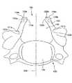
図2に示すように、椎骨(椎体)100は、椎体110と、椎体110の後方(図2中の上側)に延び、脊柱管(椎孔)140を形成する椎弓120と、椎弓120の中央部から後方に突出する棘突起130とを有している。 As shown in FIG. 2, the vertebra (vertebral body) 100 includes a
[1] まず、図2に示すように、椎骨100における棘突起130を、椎弓120から切断線131において切離(切断)する。 [1] First, as shown in FIG. 2, the
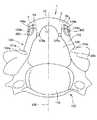
[2] 次に、図3に示すように、椎弓120の中央部(正中部)を、例えばエアドリル等を用いて切断する。 [2] Next, as shown in FIG. 3, the central portion (midline portion) of the
また、正中面200を境にして椎弓120の根元部の外側に、例えばエアドリル等を用いて溝121a、121bを形成する。 Further,
この溝121a、121bの深さは、外板のみ削り、内板を削らない程度とする。この溝121a、121bを形成した部位は、ヒンジ部(蝶番)122a、122bとなる。 The depths of the
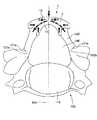
[3] 次に、図4に示すように、ヒンジ部122a、122bを中心に、椎弓120を回動させ、椎弓120の切断した部分を広げる。これにより、間隙150が形成される。 [3] Next, as shown in FIG. 4, the
なお、必要に応じて、椎弓120の間隙150に臨む切断端部120a、120bを、スペーサ1の形状に対応するように整形する。 If necessary, the cut ends 120 a and 120 b facing the
[4] 次に、図5に示すように、切断端部120a、120bに、それぞれ、次工程[5]において糸300を挿通する貫通孔123a、123bを、例えばエアドリル等を用いて形成する。 [4] Next, as shown in FIG. 5, through
[5] 次に、図6に示すように、間隙150に、本発明のスペーサ1を挿入した後、貫通孔123a、123bと貫通孔4、5とに固定部材としての糸300を挿通して縛る(縫合する)ことによりスペーサ1を間隙150内に固定する。これにより、患者の椎弓120と、スペーサ1とで、拡大された椎弓160が形成される。 [5] Next, as shown in FIG. 6, after inserting the spacer 1 of the present invention into the
なお、スペーサ1と切断端部120a、120bとを糸300で縛り、スペーサ1を間隙150内に固定する構成とすることにより、術後早期に、スペーサ1が椎弓120に対して位置ズレするのを防止することができ、切断端部120a、120bと面13、14、15、16との間における骨癒合を確実に生じさせることができる。 In addition, the spacer 1 and the cutting
固定部材は、上述のような糸300に限らず、例えばワイヤー等の他の線状体であってもよい。 The fixing member is not limited to the
なお、前記工程[1]において切離された棘突起130を、スペーサ1の第2の面12の中央(正中)に戻し、スペーサ1に糸等により固定し、棘突起130とスペーサ1との骨癒合を図るようにしてもよい。 In addition, the
また、棘突起130を椎弓120から切離することなく、前記工程[2]において、棘突起130ごと正中面200に沿って切断してもよい。 Further, the
さらに、椎弓120を途中で切離して、すなわち、切断端部120a、120bとヒンジ部122a、122bとの間で椎弓120を切離して、間隙150をより大きくし、この間隙150に、スペーサ1を挿入するようにしてもよい。 Further, the
<<スペーサ>>
次に、本発明のスペーサの第1実施形態について、図1および図6を参照して説明する。<< Spacer >>
Next, a first embodiment of the spacer of the present invention will be described with reference to FIG. 1 and FIG.
なお、以下の説明では、特に断らない限り、スペーサ1を患者の施術部位(間隙150)に挿入(装着)した状態を基本として方向を特定する。すなわち、患者の腹側(脊柱管140側)を「前」、背側(脊柱管140と反対側)を「後」といい、患者の頭側を「上」、患者の脚側を「下」という。 In the following description, unless otherwise specified, the direction is specified based on the state in which the spacer 1 is inserted (attached) into the treatment site (gap 150) of the patient. That is, the patient's ventral side (
図1および図6に示すように、スペーサ1は、間隙150に挿入されるスペーサ本体2と、椎弓120の切断端部120a、120bの後側に係合する係合部3a、3bとを有している。 As shown in FIGS. 1 and 6, the spacer 1 includes a spacer body 2 inserted into the
また、図1(b)に示す平面視で、スペーサ1は、主に、第1の面11と、第2の面12と、第3の面13と、第4の面14と、第5の面15と、第6の面16とで囲まれて形成される形状をなしている。 In the plan view shown in FIG. 1B, the spacer 1 mainly includes the
図6に示すように、このスペーサ1は、スペーサ本体2が間隙150に挿入された状態で、正中面200に対して、ほぼ線対称な形状をなしている。また、第1の面11は、この状態で、拡大された椎弓160の内側(脊柱管140)に臨む面(前面)であり、第2の面は、第1の面11に対向する位置で、拡大された椎弓160の外側に臨む面(後面)である。 As shown in FIG. 6, the spacer 1 has a substantially line-symmetric shape with respect to the
本発明では、第1の面(湾曲凹面)11および第2の面(湾曲凸面)12は、ともに湾曲面をなしているが、この点については、後に詳述する。 In the present invention, the first surface (curved concave surface) 11 and the second surface (curved convex surface) 12 are both curved surfaces, which will be described in detail later.
また、第3の面13、第4の面14、第5の面15および第6の面16は、それぞれ、ほぼ平面(平坦面)をなしている。 The
第1の面11は、第2の面12より長く形成されている。また、第3の面13は、第4の面14と鋭角をなすように形成されている。第5の面15は、第6の面16と鋭角をなすように形成されている。さらに、第3の面13は、第4の面14とほぼ同様の長さに形成されている。第5の面15は、第6の面16とほぼ同様の長さに形成されている。また、係合部3a、3bの後面は、第2の面12の湾曲面の延長線上に沿って湾曲に形成されている。スペーサ1をかかる構成とすることで、スペーサ本体2と係合部3a、3bとが形成されている。 The
このようなスペーサ1において、図1に示すように、スペーサ本体2は、主に、第1の面11と第2の面12の中央部分と、第4の面14と、第5の面15とで囲まれる部分により構成されている。また係合部3aは、主に、第2の面12の切断端部120a側の端部と、第3の面13とで囲まれる部分により構成され、係合部3bは、主に、第2の面12の切断端部120b側の端部と、第6の面16とで囲まれる部分により構成されている。 In such a spacer 1, as shown in FIG. 1, the spacer main body 2 mainly includes a central portion of the
図6に示すように、椎弓120が切断された切断端部120aの後面124aおよび側面125aは、それぞれ、第3の面13および第4の面14に当接(または接近)し、切断端部120bの後面124bおよび側面125bは、それぞれ、第6の面16および第5の面15に当接する。 As shown in FIG. 6, the
すなわち、第3の面13および第6の面16は、後面124a、bに当接する一対の当接面を構成し、第4の面14および第5の面15は、側面125a、bに当接する一対の当接面を構成する。これにより、スペーサ本体2の一部が間隙150内に挿入され、係合部3a、3bがそれぞれ切断端部120a、120bに係合し、その結果、スペーサ1が間隙150内に固定され、スペーサ1の位置ズレが的確に防止または抑制される。 That is, the
このような構成のスペーサ1において、前述したように、本発明では、第1の面11および第2の面12は、ともに湾曲面をなしている。これにより、スペーサ1(スペーサ本体2)は、その全体形状がアーチ状をなすものとなる。 In the spacer 1 having such a configuration, as described above, in the present invention, the
ここで、第1の面11および第2の面12が、湾曲状をなすことなく、ともに平面で構成されている場合には、スペーサ1は、その全体形状が桁橋状をなすものとなる。この場合、第2の面12の中央部に背側から応力が掛かると、係合部3a、3bに反発応力が掛かり、これに起因して、スペーサ1にたわみが生じ、その厚さ等によっては、第1の面11の中央部や、係合部3a、3bにおいて亀裂が生じる恐れがある。 Here, when both the
これに対して、本発明のように、第1の面11および第2の面12をともに湾曲面で構成して、スペーサ1の全体形状を、アーチ状をなすものとすることにより、スペーサ1を優れた機械的強度を発揮するものとすることができる。したがって、スペーサ1の厚さを薄く、すなわち第1の面11と第2の面12との離間距離を比較的近く設定したとしても、スペーサ1を充分な機械的強度を有するものとすることができる。すなわち、スペーサ1の厚みを厚くすることが無く、横幅(後述の図1中のL2)の広い(長い)スペーサが実現可能となる。そのため、頸椎、胸椎、特に負荷の大きい腰椎のような何れのサイズの椎体に対する、前述した正中縦割式拡大椎弓形成術においても、スペーサ1を適用することが可能となるとともに、いかなる体格の患者においても全脊椎に対して適用が可能となる。On the other hand, as in the present invention, the
これは、スペーサ1の全体形状を、アーチ状をなすものとすることで、図7に示すように、第2の面12の中央部に背側から応力が掛った際の反発応力が、上下方向と左右方向の双方で生じることとなるため、スペーサ本体2の断面内に一様な圧縮力が生じるのみに止まることに起因する。 This is because the overall shape of the spacer 1 has an arch shape, and as shown in FIG. 7, the repulsive stress when the stress is applied from the back side to the center of the
また、第1の面11は、その湾曲形状がカテナリー曲線(懸垂曲線)をなしているのが好ましい。 Moreover, it is preferable that the curved shape of the
ここで、カテナリー曲線は、ロープや電線等の線状体の両端を垂らした際に形成される曲線であり、媒介変数をaとしたとき、下記式(1)で表わされ、力学的に安定している。 Here, the catenary curve is a curve formed when both ends of a linear body such as a rope or an electric wire are hung, and is represented by the following formula (1) when the parameter is a, and is mechanically stable.
y=a・cosh(x/a)
=a/2・{exp(x/a)+exp(−x/a)} …… 式1y = a · cosh (x / a)
= A / 2 · {exp (x / a) + exp (−x / a)} Equation 1
そのため、第1の面11の形状をカテナリー曲線をなすものとすることで、スペーサ1をより優れた機械的強度を発揮するものとすることができる。 Therefore, by making the shape of the first surface 11 a catenary curve, the spacer 1 can exhibit more excellent mechanical strength.
さらに、かかる観点から、第2の面12も、その湾曲形状がカテナリー曲線(懸垂曲線)をなしているのが好ましい。これにより、前記効果をより顕著に発揮させることができる。 Further, from this point of view, it is preferable that the
また、本実施形態では、第1の面11の長さ(図1中のL1)は、第2の面12の長さ(図1中のL2)よりも短くなっている。これにより、スペーサ1を、第3の面13において後面124aと、第4の面14において側面125aと、第5の面15において側面125bと、第6の面16において後面124bと、それぞれ当接し得る形状をなすものとすることができる。さらに、第1の面11の曲率半径を第2の面12の曲率半径よりも小さく設定することが可能となることから、かかる構成とすることで、脊柱管140をより大きく(広く)拡大することすなわち間隙150をより大きく確保することができ、脊髄神経の圧迫を確実に防止することができるようになる。したがって、このようなスペーサ1は、前述した正中縦割式拡大椎弓形成術に適用できるばかりでなく、図8に示すように、椎弓120の途中で切離する椎弓切除術(ラミネクトミー)で形成された間隙150にスペーサ1を挿入する椎弓形成術にも適用可能となる。スペーサ1の厚みが薄くカテナリーアーチ曲線によるワイドスペースは、椎弓が薄く、脊柱管の拡大率の増大が要求される頚椎や上位胸椎にて、より威力を発揮する。In the present embodiment, the length of the first surface 11 (L1 in FIG. 1) is shorter than the length of the second surface 12 (L2 in FIG. 1). Thus, the spacer 1 contacts the
さらに、第1の面11の長さが第2の面12の長さよりも短く、かつ、第1の面11および第2の面12の形状がカテナリー曲線をなす場合、第1の面11の媒介変数をa1とし、第2の面12の媒介変数をa2としたとき、a2/a1は、好ましくは1〜8程度、より好ましくは2〜4程度に設定される。これにより、スペーサ1を優れた機械的強度を付与しつつ、脊柱管140をより大きく拡大することができる。 Furthermore, when the length of the
図1(a)、(b)に示すように、スペーサ1の上面17と下面18とは、それぞれ、ほぼ平面状をなすものの、その中央部において、若干湾曲凹面をなすものである。かかる構成とすることにより、スペーサの垂直断面は略台形形状となり、スペーサへの負荷に対してより安定性が増すという利点も得られる。 As shown in FIGS. 1 (a) and 1 (b), the
また、上面17と、下面18とは、前方(第1の面11)側から、後方(第2の面12)側に向かって互いに近づいている。すなわち、スペーサ1の厚さ(上下方向の寸法)は、前方から後方に向かって漸減している(図1(c)中のL4>L5である。)。スペーサ1の垂直断面は、略台形形状である。かかる構成とすることにより、スペーサ1の重心が第1の面11側に位置することになる。すなわち、スペーサ本体2の間隙150内に挿入される部分に、スペーサ1の重心が位置することになる。そのため、スペーサ1の間隙150内への挿入後に、スペーサ1に背側から負荷が掛って何らかの応力にかわって、スペーサ1が位置ズレしてしまうのを的確に防止または抑制することができる。In addition, the
また、上面17と下面18とのなす角度θは、特に限定されないが、5〜30°程度であるのが好ましく、10〜25°程度であるのがより好ましい。これにより、前記効果をより顕著に発揮させることができるようになる。 In addition, the angle θ formed by the
スペーサ1の最大厚さ(図1中のL4)は、特に限定されないが、5〜15mm程度であるのが好ましく、8〜12mm程度であるのがより好ましい。また、最小厚さ(図1中のL5)は、特に限定されないが、3〜10mm程度であるのが好ましく、4〜7mm程度であるのがより好ましい。The maximum thickness (L4 in FIG. 1) of the spacer 1 is not particularly limited, but is preferably about 5 to 15 mm, and more preferably about 8 to 12 mm. Further, the minimum thickness (L5 in FIG. 1) is not particularly limited, but is preferably about 3 to 10 mm, and more preferably about 4 to 7 mm.
なお、図示の構成では、スペーサ1のほぼ全長にわたって前方から後方に向かって厚さが漸減する構成となっているが、全長の一部において前方から後方に向かって厚さが漸減するようなものであっても、上記と同様の効果が得られる。 In the configuration shown in the figure, the thickness gradually decreases from the front to the rear over substantially the entire length of the spacer 1, but the thickness gradually decreases from the front to the rear in a part of the total length. Even so, the same effect as described above can be obtained.
また、第1の面11と第4の面14とで形成される角部付近と、第1の面11と第5の面15とで形成される角部付近とは、それそれ、面取りがなされている。これにより、スペーサ1の欠け(破損)が防止されるとともに、間隙150へのスペーサ1の挿入を、前記角部が切断端部120a、120bに引っ掛かることなく、より容易に行うことができる。 Further, the chamfer between the vicinity of the corner formed by the
さらに、係合部3a、3bの厚さ(面12と面13、16との離間距離)は、それぞれ、特に限定されないが、5〜7mm程度であるのが好ましく、4〜6mm程度であるのがより好ましい。係合部3a、3bの厚さを上記範囲のように比較的厚く設定することで、第2の面12の中央部に背側から負荷が掛った際に、係合部3a、3bにおいて亀裂が生じるのを確実に防止することができる。 Furthermore, the thickness of the engaging
このようなスペーサ1において、第1の面11の長さ(図1中のL1)、第2の面12の長さ(図1中のL2)および第1の面11と第2の面12との(最大)距離(図1中のL3)等の各寸法は、頸椎、胸椎、腰椎のような椎体の種類や、症例に応じて適宜決定されるが、概ね、以下に示すような範囲内に設定される。In such a spacer 1, the length of the first surface 11 (L1 in FIG.1 ), the length of the second surface 12 (L2 in FIG. 1), and the
すなわち、第1の面11の長さ(図1中のL1)は、好ましくは6〜25mm程度、より好ましくは8〜22mm程度に設定される。That is, the length of the first surface 11 (L1 in FIG.1 ) is preferably set to about 6 to 25 mm, more preferably about 8 to 22 mm.
また、第2の面12の長さ(図1中のL2)は、好ましくは10〜25mm程度、より好ましくは16〜21mm程度に設定される。The length of the second surface 12 (L2 in FIG. 1) is preferably set to about 10 to 25 mm, more preferably about 16 to 21 mm.
さらに、第1の面11と第2の面12との(最大)距離(図1中のL3)は、好ましくは6〜15mm程度、より好ましくは9〜12mm程度に設定される。Furthermore, the (maximum) distance (L3 in FIG. 1) between the
なお、本実施形態では、第3の面13、第4の面14、第5の面15、第6の面16、上面17および下面18は、それぞれ、ほぼ平面になっているが、これに限定されず、平面になっていなくてもよい。 In the present embodiment, the
また、図1に示すように、スペーサ1には、第1の面11の切断端部120a側の部分から第3の面13まで貫通する貫通孔4が形成され、第1の面11の切断端部120b側の部分から第6の面16まで貫通する貫通孔5が形成されている。すなわち、係合部3a、3bにそれぞれ貫通孔4、5が形成されている。これにより、貫通孔4、5には、それぞれ、固定部材としての糸300を挿通可能となっている。 Further, as shown in FIG. 1, the spacer 1 is formed with a through
図6に示すように、椎弓120の切断端部120aに形成された貫通孔123aと貫通孔4とに糸300を挿通して縛る(縫合する)ことにより、切断端部120aにスペーサ1を固定することができ、さらに、切断端部120bに形成された貫通孔123bと貫通孔5とに糸300を挿通して縛ることにより、切断端部120bにスペーサ1を固定することができる。これにより、術後、スペーサ1の位置ズレをより確実に防止することができる。 As shown in FIG. 6, the thread 1 is inserted into the through
貫通孔4、5の平均内径は、それぞれ、Φ0.5〜Φ5mm程度であるのが好ましく、Φ1.5〜Φ2.5mm程度であるのがより好ましい。 The average inner diameters of the through-
なお、貫通孔4、5の個数は、それぞれ、図示の構成に限定されないことは言うまでもない。また、固定部材は、糸300に限らず、例えば、ワイヤー等の他の線状体や、ボルト等であってもよい。 Needless to say, the number of the through
図1に示すように、第2の面12に形成された貫通孔4の開口41の縁部から、第2の面12の端部にかけての部位には、糸300が挿入可能な溝42が形成されている。また、第2の面12に形成された貫通孔5の開口51の縁部から、第2の面12の端部にかけての部位には、糸300が挿入可能な溝52が形成されている。 As shown in FIG. 1, a
図6に示す状態から、各々の糸300をさらに緊張させて縛ると、各々の糸300は、それぞれ、溝42、52内に挿入する。これにより、糸300の位置ズレ・緩み等を防止することができ、糸300による固定をより確実に維持することができる。 When each
溝42、52の深さは、特に限定されないが、1〜3mm程度であるのが好ましく、1.2〜2mm程度であるのがより好ましい。溝42、52の深さを上記範囲のように比較的深く設定することで、糸300による固定をより確実に維持することができるため、間隙150からのスペーサ1の脱転が防止される。 The depth of the
また、スペーサ1は、その全体に亘って、角部が丸みを帯びた形状をなしている(R付けがなされている)ものであってもよい。かかる構成とすることにより、スペーサ1を間隙150に挿入する際に、周辺組織を傷付けるのを防止することができるという利点が得られる。 Further, the spacer 1 may have a shape with rounded corners (R-attached) over the entirety thereof. With this configuration, there is an advantage that it is possible to prevent the surrounding tissue from being damaged when the spacer 1 is inserted into the
このようなスペーサ1は、セラミックス材料を主材料として構成されたものが好ましい。セラミックス材料は加工性に優れているため、スペーサ1の製造工程において、旋盤、ドリル等を用いた切削加工によりその形状、大きさ等を調整することが容易である。 Such a spacer 1 is preferably made of a ceramic material as a main material. Since the ceramic material is excellent in workability, in the manufacturing process of the spacer 1, it is easy to adjust its shape, size, etc. by cutting using a lathe, a drill or the like.
セラミックス材料としては、各種のものが挙げられるが、特に、アルミナ、ジルコニア、リン酸カルシウム系化合物等のバイオセラミックスが好ましい。なかでもリン酸カルシウム系化合物は、優れた生体親和性を備えているため、スペーサ1の構成材料として特に好ましい。 Examples of the ceramic material include various materials, and bioceramics such as alumina, zirconia, and calcium phosphate compounds are particularly preferable. Among these, a calcium phosphate compound is particularly preferable as a constituent material of the spacer 1 because it has excellent biocompatibility.
リン酸カルシウム系化合物としては、例えば、ハイドロキシアパタイト、フッ素アパタイト、炭酸アパタイト等のアパタイト類、リン酸二カルシウム、リン酸三カルシウム、リン酸四カルシウム、リン酸八カルシウム等が挙げられ、これらのうちの1種または2種以上を組み合わせて用いることができる。また、これらのリン酸カルシウム系化合物のなかでもCa/P比が1.0〜2.0のものが好ましく用いられる。 Examples of the calcium phosphate compound include apatites such as hydroxyapatite, fluorapatite, and carbonate apatite, dicalcium phosphate, tricalcium phosphate, tetracalcium phosphate, octacalcium phosphate, and the like. Species or a combination of two or more can be used. Of these calcium phosphate compounds, those having a Ca / P ratio of 1.0 to 2.0 are preferably used.
このようなリン酸カルシウム系化合物のうち、ハイドロキシアパタイトがより好ましい。ハイドロキシアパタイトは、骨の無機質主成分と同様の構造であるため、優れた生体適合性を有している。また、スペーサ1自体と切断端部120a、120bとの癒合を期待することもできる。 Of such calcium phosphate compounds, hydroxyapatite is more preferable. Hydroxyapatite has an excellent biocompatibility because it has the same structure as the mineral main component of bone. Further, it is possible to expect the fusion between the spacer 1 itself and the cut ends 120a and 120b.
また、スペーサ1は、緻密体であっても、多孔質体であってもよいが、多孔質体であるのが好ましい。スペーサ1を多孔質体で構成することにより、スペーサ1内への骨芽細胞の侵入を可能とし、スペーサ1内において骨新生を行うことができ、特に、スペーサ1を、ハイドロキシアパタイトを主材料として構成する場合、スペーサ1自体と切断端部120a、120bとの確実な癒合を期待することができる。 The spacer 1 may be a dense body or a porous body, but is preferably a porous body. By constituting the spacer 1 with a porous body, it is possible to invade osteoblasts into the spacer 1 and perform osteogenesis in the spacer 1. In particular, the spacer 1 is mainly composed of hydroxyapatite. When configured, it is possible to expect reliable fusion between the spacer 1 itself and the cut ends 120a and 120b.
なお、スペーサ1は、上述のように、そのほぼ全てが緻密体または多孔質体で構成される場合に限定されず、その一部が多孔質体で構成され、それ以外の部分が緻密体で構成されるものであってもよい。 As described above, the spacer 1 is not limited to a case where almost all of the spacer 1 is formed of a dense body or a porous body. A part of the spacer 1 is formed of a porous body, and the other part is a dense body. It may be configured.
また、多孔質体の空孔率は、0〜90%程度であるのが好ましく、15〜60%程度であるのがより好ましい。これにより、スペーサ(多孔質体)1の機械的強度が低下するのを防止しつつ、スペーサ1内への骨芽細胞のより円滑な侵入を可能とし、スペーサ1内における骨新生が促進することとなる。その結果、切断端部120a、120bと面13、14、15、16との間における骨癒合をより確実かつ早期に生じさせることができる。 Further, the porosity of the porous body is preferably about 0 to 90%, more preferably about 15 to 60%. Thereby, while preventing the mechanical strength of the spacer (porous body) 1 from being lowered, it is possible to allow osteoblasts to enter the spacer 1 more smoothly and to promote osteogenesis in the spacer 1. It becomes. As a result, bone fusion between the
なお、スペーサ1の構成材料としては、上記セラミックス材料の他、該セラミックス材料とチタン等の生体為害性の小さい金属材料との複合材料等を用いることも可能である。 As a constituent material of the spacer 1, in addition to the above ceramic material, a composite material of the ceramic material and a metal material having a low biological harm such as titanium can be used.
以上、本発明のスペーサを図示の実施形態に基づいて説明したが、本発明は、これに限定されるものではない。 As mentioned above, although the spacer of this invention was demonstrated based on embodiment of illustration, this invention is not limited to this.
例えば、本発明のスペーサにおいて、各構成は、同様の機能を発揮し得る任意のものと置換することができ、あるいは、任意の構成のものを付加することができる。 For example, in the spacer of the present invention, each component can be replaced with any component that can exhibit the same function, or any component can be added.
また、前記実施形態では、スペーサ1を正中縦割式拡大椎弓形成術に用いる場合について示したが、本発明では、スペーサを、椎弓の一方側(片側)を切断し、他方側をヒンジのようにして椎弓を開くことにより脊柱管を拡大する片側侵入片開き式脊柱管拡大術に用いるようにしてもよい。 In the above embodiment, the spacer 1 is used for the mid-vertical split-type enlarged laminoplasty. However, in the present invention, the spacer is cut on one side (one side) of the vertebra and the other side is hinged. As described above, the spinal canal may be expanded by expanding the spinal canal by opening the vertebral arch.
1、10、10’ スペーサ
11 第1の面
12 第2の面
13 第3の面
14 第4の面
15 第5の面
16 第6の面
17 上面
18 下面
2 スペーサ本体
3a、3b 係合部
4、5 貫通孔
41、51 開口
42、52 溝
100 椎骨
101、102 面
103、106 フランジ
104、105 当接面
110 椎体
120 椎弓
120a、120b 切断端部
121a、121b 溝
122a、122b ヒンジ部
123a、123b 貫通孔
124a、124b 後面
125a、125b 側面
130 棘突起
131 切断線
140 脊柱管
150 間隙
160 拡大された椎弓
200 正中面
300 糸DESCRIPTION OF
Claims (7)
Translated fromJapanese少なくとも一部が前記間隙に挿入され、当該間隙に挿入された状態で、脊柱管側に位置する前面と、該前面に対向して位置する後面と、前記椎弓または棘突起の切断端部にそれぞれ当接する一対の当接面とを有し、
前記前面と前記後面とは、ともに、湾曲面で構成され、さらに、その湾曲形状がカテナリー曲線をなしており、
前記前面の横幅の長さは、前記後面の横幅の長さよりも短く、かつ、前記前面の曲率半径は、前記後面の曲率半径よりも小さくなっていることを特徴とするスペーサ。A spacer used to expand a spinal canal by inserting into a gap formed by cutting and opening a vertebral arch or spinous process,
At least a portion is inserted into the gap, and in a state of being inserted into the gap, a front surface located on the spinal canal side, a rear surface located opposite to the front surface, and a cut end portion of the vertebral arch or spinous process A pair of contact surfaces that contact each other,
The front surface and the rear surface are both configured by curved surfaces,and the curved shape forms a catenary curve,
The spacer is characterized in that a width of the front surface is shorter than a width of the rear surface, and a curvature radius of the front surface is smaller than a curvature radius of the rear surface .
Priority Applications (1)
| Application Number | Priority Date | Filing Date | Title |
|---|---|---|---|
| JP2010121882AJP5654263B2 (en) | 2010-05-27 | 2010-05-27 | Spacer |
Applications Claiming Priority (1)
| Application Number | Priority Date | Filing Date | Title |
|---|---|---|---|
| JP2010121882AJP5654263B2 (en) | 2010-05-27 | 2010-05-27 | Spacer |
Publications (2)
| Publication Number | Publication Date |
|---|---|
| JP2011245061A JP2011245061A (en) | 2011-12-08 |
| JP5654263B2true JP5654263B2 (en) | 2015-01-14 |
Family
ID=45411046
Family Applications (1)
| Application Number | Title | Priority Date | Filing Date |
|---|---|---|---|
| JP2010121882AActiveJP5654263B2 (en) | 2010-05-27 | 2010-05-27 | Spacer |
Country Status (1)
| Country | Link |
|---|---|
| JP (1) | JP5654263B2 (en) |
Families Citing this family (2)
| Publication number | Priority date | Publication date | Assignee | Title |
|---|---|---|---|---|
| US9717541B2 (en) | 2015-04-13 | 2017-08-01 | DePuy Synthes Products, Inc. | Lamina implants and methods for spinal decompression |
| JP6537432B2 (en)* | 2015-10-19 | 2019-07-03 | HOYA Technosurgical株式会社 | Spacer |
Family Cites Families (8)
| Publication number | Priority date | Publication date | Assignee | Title |
|---|---|---|---|---|
| JPS5022486A (en)* | 1973-06-29 | 1975-03-10 | ||
| JP4100890B2 (en)* | 2001-09-11 | 2008-06-11 | ペンタックス株式会社 | Lingual spacer |
| JP2004089326A (en)* | 2002-08-30 | 2004-03-25 | Akira Nai | Artificial vertebral arch member and artificial vertebral body member |
| WO2006073402A1 (en)* | 2005-01-07 | 2006-07-13 | Blackstone Medical, Inc. | Vertebral body replacement apparatus and method |
| US7780722B2 (en)* | 2005-02-07 | 2010-08-24 | Boston Scientific Scimed, Inc. | Venous valve apparatus, system, and method |
| US7914569B2 (en)* | 2005-05-13 | 2011-03-29 | Medtronics Corevalve Llc | Heart valve prosthesis and methods of manufacture and use |
| JP4386448B2 (en)* | 2005-12-19 | 2009-12-16 | 敏且 侭田 | Spinous process spacer |
| JP2007301244A (en)* | 2006-05-12 | 2007-11-22 | Pentax Corp | Spacer and spacer manufacturing method |
- 2010
- 2010-05-27JPJP2010121882Apatent/JP5654263B2/enactiveActive
Also Published As
| Publication number | Publication date |
|---|---|
| JP2011245061A (en) | 2011-12-08 |
Similar Documents
| Publication | Publication Date | Title |
|---|---|---|
| ES2266543T3 (en) | LAMINOPLASTIC IMPLANTS WITH CAPTURED GRAFT. | |
| CA2887199C (en) | Intervertebral spacers | |
| JP4100890B2 (en) | Lingual spacer | |
| US20150081026A1 (en) | Spinal Spacer | |
| EP1718223B1 (en) | Intramedullary nail | |
| KR102360208B1 (en) | Cage for spinal surgery | |
| KR20160042821A (en) | Interbody cage | |
| KR101146572B1 (en) | Interspinal spacer | |
| JP2006021056A (en) | Spine correction system | |
| KR20200053515A (en) | Intervertebral implant | |
| US20220202574A1 (en) | System Comprising A Foam Structure And A Surgical Fixation Device | |
| JP5654263B2 (en) | Spacer | |
| JP5184971B2 (en) | Spacer | |
| US20200146836A1 (en) | Implant device for performing posterior spinal arthrodesis at a facet joint | |
| JP6871709B2 (en) | Spacer | |
| JP2007301244A (en) | Spacer and spacer manufacturing method | |
| JP5893332B2 (en) | Spacer | |
| JP4536631B2 (en) | Spacer | |
| JP5798443B2 (en) | Spacer | |
| JP2013075120A (en) | Spacer | |
| JP6502161B2 (en) | Bone cement | |
| JP5854361B1 (en) | Artificial bone spacer | |
| JP6537432B2 (en) | Spacer | |
| JP2013144078A (en) | Spacer and loop wire | |
| JP3768508B2 (en) | Spine surgery spacer |
Legal Events
| Date | Code | Title | Description |
|---|---|---|---|
| A621 | Written request for application examination | Free format text:JAPANESE INTERMEDIATE CODE: A621 Effective date:20121213 | |
| A977 | Report on retrieval | Free format text:JAPANESE INTERMEDIATE CODE: A971007 Effective date:20131118 | |
| A131 | Notification of reasons for refusal | Free format text:JAPANESE INTERMEDIATE CODE: A131 Effective date:20131126 | |
| A521 | Request for written amendment filed | Free format text:JAPANESE INTERMEDIATE CODE: A523 Effective date:20140124 | |
| A711 | Notification of change in applicant | Free format text:JAPANESE INTERMEDIATE CODE: A712 Effective date:20140703 | |
| A521 | Request for written amendment filed | Free format text:JAPANESE INTERMEDIATE CODE: A523 Effective date:20140805 | |
| TRDD | Decision of grant or rejection written | ||
| A01 | Written decision to grant a patent or to grant a registration (utility model) | Free format text:JAPANESE INTERMEDIATE CODE: A01 Effective date:20141028 | |
| A61 | First payment of annual fees (during grant procedure) | Free format text:JAPANESE INTERMEDIATE CODE: A61 Effective date:20141120 | |
| R150 | Certificate of patent or registration of utility model | Ref document number:5654263 Country of ref document:JP Free format text:JAPANESE INTERMEDIATE CODE: R150 | |
| S111 | Request for change of ownership or part of ownership | Free format text:JAPANESE INTERMEDIATE CODE: R313117 | |
| R350 | Written notification of registration of transfer | Free format text:JAPANESE INTERMEDIATE CODE: R350 | |
| R250 | Receipt of annual fees | Free format text:JAPANESE INTERMEDIATE CODE: R250 | |
| R250 | Receipt of annual fees | Free format text:JAPANESE INTERMEDIATE CODE: R250 | |
| R250 | Receipt of annual fees | Free format text:JAPANESE INTERMEDIATE CODE: R250 | |
| R250 | Receipt of annual fees | Free format text:JAPANESE INTERMEDIATE CODE: R250 | |
| R250 | Receipt of annual fees | Free format text:JAPANESE INTERMEDIATE CODE: R250 | |
| R250 | Receipt of annual fees | Free format text:JAPANESE INTERMEDIATE CODE: R250 | |
| R250 | Receipt of annual fees | Free format text:JAPANESE INTERMEDIATE CODE: R250 | |
| R250 | Receipt of annual fees | Free format text:JAPANESE INTERMEDIATE CODE: R250 |