JP5654217B2 - Contrast markers and catheters - Google Patents
Contrast markers and cathetersDownload PDFInfo
- Publication number
- JP5654217B2 JP5654217B2JP2009135262AJP2009135262AJP5654217B2JP 5654217 B2JP5654217 B2JP 5654217B2JP 2009135262 AJP2009135262 AJP 2009135262AJP 2009135262 AJP2009135262 AJP 2009135262AJP 5654217 B2JP5654217 B2JP 5654217B2
- Authority
- JP
- Japan
- Prior art keywords
- catheter
- contrast marker
- peripheral surface
- contrast
- marker
- Prior art date
- Legal status (The legal status is an assumption and is not a legal conclusion. Google has not performed a legal analysis and makes no representation as to the accuracy of the status listed.)
- Expired - Fee Related
Links
- 239000003550markerSubstances0.000claimsdescription241
- 230000002093peripheral effectEffects0.000claimsdescription119
- 239000007769metal materialSubstances0.000claimsdescription7
- 238000003384imaging methodMethods0.000claimsdescription4
- 239000000463materialSubstances0.000description78
- 238000000034methodMethods0.000description33
- 238000004519manufacturing processMethods0.000description31
- 229910052751metalInorganic materials0.000description18
- 239000002184metalSubstances0.000description18
- 238000004804windingMethods0.000description18
- 230000001105regulatory effectEffects0.000description11
- 238000010586diagramMethods0.000description6
- 208000031481Pathologic ConstrictionDiseases0.000description5
- 210000004204blood vesselAnatomy0.000description5
- 238000001816coolingMethods0.000description5
- 238000010438heat treatmentMethods0.000description5
- 230000036262stenosisEffects0.000description5
- 208000037804stenosisDiseases0.000description5
- 230000004927fusionEffects0.000description4
- 238000003780insertionMethods0.000description4
- 230000037431insertionEffects0.000description4
- 239000002861polymer materialSubstances0.000description3
- PPBRXRYQALVLMV-UHFFFAOYSA-NStyreneChemical compoundC=CC1=CC=CC=C1PPBRXRYQALVLMV-UHFFFAOYSA-N0.000description2
- 238000005219brazingMethods0.000description2
- 238000000576coating methodMethods0.000description2
- 239000000470constituentSubstances0.000description2
- 229920001577copolymerPolymers0.000description2
- 230000007423decreaseEffects0.000description2
- BASFCYQUMIYNBI-UHFFFAOYSA-NplatinumChemical compound[Pt]BASFCYQUMIYNBI-UHFFFAOYSA-N0.000description2
- 229920002401polyacrylamidePolymers0.000description2
- 238000002360preparation methodMethods0.000description2
- 239000011347resinSubstances0.000description2
- 229920005989resinPolymers0.000description2
- 238000005476solderingMethods0.000description2
- 239000000126substanceSubstances0.000description2
- PKAUISBSZACZJI-UHFFFAOYSA-NCC(=CC(=O)N)C.C(C(=C)C)(=O)OChemical compoundCC(=CC(=O)N)C.C(C(=C)C)(=O)OPKAUISBSZACZJI-UHFFFAOYSA-N0.000description1
- 239000004709Chlorinated polyethyleneSubstances0.000description1
- YCKRFDGAMUMZLT-UHFFFAOYSA-NFluorine atomChemical compound[F]YCKRFDGAMUMZLT-UHFFFAOYSA-N0.000description1
- 229910000990Ni alloyInorganic materials0.000description1
- 239000004677NylonSubstances0.000description1
- 229920003171Poly (ethylene oxide)Polymers0.000description1
- 239000004952PolyamideSubstances0.000description1
- 239000005062PolybutadieneSubstances0.000description1
- 239000004743PolypropyleneSubstances0.000description1
- 239000004372Polyvinyl alcoholSubstances0.000description1
- 238000010521absorption reactionMethods0.000description1
- 239000000853adhesiveSubstances0.000description1
- 230000001070adhesive effectEffects0.000description1
- 229910045601alloyInorganic materials0.000description1
- 239000000956alloySubstances0.000description1
- 210000001367arteryAnatomy0.000description1
- 239000010953base metalSubstances0.000description1
- 210000000013bile ductAnatomy0.000description1
- 229920001400block copolymerPolymers0.000description1
- 239000008280bloodSubstances0.000description1
- 210000004369bloodAnatomy0.000description1
- 229920003174cellulose-based polymerPolymers0.000description1
- 239000011248coating agentSubstances0.000description1
- ZGDWHDKHJKZZIQ-UHFFFAOYSA-Ncobalt nickelChemical compound[Co].[Ni].[Ni].[Ni]ZGDWHDKHJKZZIQ-UHFFFAOYSA-N0.000description1
- 230000006835compressionEffects0.000description1
- 238000007906compressionMethods0.000description1
- 238000007598dipping methodMethods0.000description1
- 238000001035dryingMethods0.000description1
- 229920001971elastomerPolymers0.000description1
- 210000003238esophagusAnatomy0.000description1
- 230000002349favourable effectEffects0.000description1
- 239000011737fluorineSubstances0.000description1
- 229910052731fluorineInorganic materials0.000description1
- 238000002594fluoroscopyMethods0.000description1
- PCHJSUWPFVWCPO-UHFFFAOYSA-NgoldChemical compound[Au]PCHJSUWPFVWCPO-UHFFFAOYSA-N0.000description1
- 229910052737goldInorganic materials0.000description1
- 239000010931goldSubstances0.000description1
- 229910052741iridiumInorganic materials0.000description1
- GKOZUEZYRPOHIO-UHFFFAOYSA-Niridium atomChemical compound[Ir]GKOZUEZYRPOHIO-UHFFFAOYSA-N0.000description1
- 239000007788liquidSubstances0.000description1
- FPYJFEHAWHCUMM-UHFFFAOYSA-Nmaleic anhydrideChemical compoundO=C1OC(=O)C=C1FPYJFEHAWHCUMM-UHFFFAOYSA-N0.000description1
- 229920001778nylonPolymers0.000description1
- 229920003023plasticPolymers0.000description1
- 239000004033plasticSubstances0.000description1
- 229910052697platinumInorganic materials0.000description1
- 229920002647polyamidePolymers0.000description1
- 229920002857polybutadienePolymers0.000description1
- 229920000728polyesterPolymers0.000description1
- 229920001195polyisoprenePolymers0.000description1
- 229920000642polymerPolymers0.000description1
- 229920002959polymer blendPolymers0.000description1
- 229920000098polyolefinPolymers0.000description1
- -1polypropylenePolymers0.000description1
- 229920001155polypropylenePolymers0.000description1
- 229920002635polyurethanePolymers0.000description1
- 239000004814polyurethaneSubstances0.000description1
- 229920002451polyvinyl alcoholPolymers0.000description1
- 229920000036polyvinylpyrrolidonePolymers0.000description1
- 239000001267polyvinylpyrrolidoneSubstances0.000description1
- 235000013855polyvinylpyrrolidoneNutrition0.000description1
- 239000005060rubberSubstances0.000description1
- 239000002904solventSubstances0.000description1
- 239000007921spraySubstances0.000description1
- 239000010935stainless steelSubstances0.000description1
- 229910001220stainless steelInorganic materials0.000description1
- 229910052715tantalumInorganic materials0.000description1
- GUVRBAGPIYLISA-UHFFFAOYSA-Ntantalum atomChemical compound[Ta]GUVRBAGPIYLISA-UHFFFAOYSA-N0.000description1
- 229920002725thermoplastic elastomerPolymers0.000description1
- 210000003437tracheaAnatomy0.000description1
- WFKWXMTUELFFGS-UHFFFAOYSA-NtungstenChemical compound[W]WFKWXMTUELFFGS-UHFFFAOYSA-N0.000description1
- 229910052721tungstenInorganic materials0.000description1
- 239000010937tungstenSubstances0.000description1
- 210000003708urethraAnatomy0.000description1
- XLYOFNOQVPJJNP-UHFFFAOYSA-NwaterSubstancesOXLYOFNOQVPJJNP-UHFFFAOYSA-N0.000description1
- 238000009736wettingMethods0.000description1
Images


Landscapes
- Media Introduction/Drainage Providing Device (AREA)
Description
Translated fromJapanese本発明は、造影マーカおよびカテーテルに関する。 The present invention relates to a contrast marker and a catheter.
例えば、血管、胆管、気管、食道、尿道などの生体内の管腔内に狭窄または閉塞が生じた場合、その狭窄部または閉塞部(以下狭窄部を代表する)を解消して、これらの機能を回復させるための治療が必要となる。このような治療は、次のようにして行なわれる。 For example, when stenosis or occlusion occurs in a living body lumen such as blood vessels, bile ducts, trachea, esophagus, urethra, etc., these stenosis or occlusions (hereinafter referred to as stenosis) are resolved and their functions Treatment is needed to recover. Such treatment is performed as follows.
まず、患者の脚または腕の動脈に小さな切開を施してイントロデューサーシース(導入器)を留置し、イントロデューサーシースの内腔を通じて、ガイドワイヤを先行させながら、カテーテルを血管内に挿入する。そして、X線造影下で、カテーテルを目的部位である狭窄部まで進める。その後、当該カテーテル内にバルーンカテーテルを挿入して、バルーンにより狭窄部を拡張する。これにより、狭窄部が解消される。 First, a small incision is made in the artery of the patient's leg or arm, an introducer sheath (introducer) is placed, and the catheter is inserted into the blood vessel through the lumen of the introducer sheath, with the guide wire leading. Then, under X-ray contrast, the catheter is advanced to the stenosis that is the target site. Thereafter, a balloon catheter is inserted into the catheter, and the stenosis is expanded with the balloon. Thereby, the constriction part is eliminated.
ところで、カテーテルは、その先端部に埋設された造影マーカ(例えば、特許文献1、2および3参照)を有しているため、操作者(医師)がX線造影下で当該カテーテルの先端部を狭窄部またはその近傍に位置させるのが容易となる。特許文献1に記載の造影マーカは、円筒状または楕円筒状をなす部材で構成され、その壁部にスリットが形成されたものである。特許文献2に記載の造影マーカは、円筒状をなす部材で構成され、その途中に径方向外側に突出したリング状の突出部(フレア)が形成されたものである。特許文献3に記載の造影マーカは、円筒状をなす部材で構成され、その外周部の両端部がそれぞれテーパ状をなすものである。 By the way, since the catheter has a contrast marker (for example, refer to
そして、造影マーカを有するカテーテルの製造としては、次のようにして行なわれる方法が知られている(例えば、特許文献4参照)。特許文献4に記載の製造方法では、まず、棒状の芯金にチューブを挿通した挿通状態とする。このとき、チューブの内周面が芯金の外周面に当接する程度に、チューブを収縮させる。次に、挿通状態の収縮したチューブに複数の造影マーカを嵌合させる。次に、各造影マーカごとチューブを加熱し、当該チューブを膨張させる。これにより、各造影マーカがチューブの外周面に食い込み、チューブに対して固定され、造影マーカを有するカテーテルが製造される。 And as a manufacture of the catheter which has a contrast marker, the method performed as follows is known (for example, refer patent document 4). In the manufacturing method described in Patent Document 4, first, the tube is inserted into a bar-shaped cored bar. At this time, the tube is contracted to such an extent that the inner peripheral surface of the tube contacts the outer peripheral surface of the cored bar. Next, a plurality of contrast markers are fitted into the contracted tube in the inserted state. Next, the tube is heated for each contrast marker, and the tube is expanded. Thereby, each contrast marker bites into the outer peripheral surface of the tube, is fixed to the tube, and a catheter having the contrast marker is manufactured.
このように、特許文献4に記載の製造方法では、造影マーカを固定するのに、チューブを収縮/膨張させたり、収縮したチューブに対して造影マーカを位置決めしたりするなどの多数の工程を経る。このため、特許文献4に記載の製造方法は、カテーテルを製造するには、煩雑な方法であると言うことができる。 As described above, in the manufacturing method described in Patent Document 4, in order to fix the contrast marker, the tube is contracted / expanded and the contrast marker is positioned with respect to the contracted tube. . For this reason, it can be said that the manufacturing method described in Patent Document 4 is a complicated method for manufacturing a catheter.
また、特許文献4に記載の製造方法により製造されたカテーテルでは、当該カテーテル(チューブ)の内周面の各造影マーカが配置された部分に、当該造影マーカが存在する分、段差部が生じてしまう(特許文献4の図6参照)。このため、カテーテル内(ルーメン内)に例えばガイドワイヤを挿入しようとした場合、そのガイドワイヤが段差部に引っ掛かってしまい、操作性に劣るという問題があった。 Further, in the catheter manufactured by the manufacturing method described in Patent Document 4, a stepped portion is generated in the portion where each contrast marker is arranged on the inner peripheral surface of the catheter (tube) due to the presence of the contrast marker. (See FIG. 6 of Patent Document 4). For this reason, for example, when trying to insert a guide wire into the catheter (inside the lumen), the guide wire is caught by the stepped portion, resulting in poor operability.
本発明の目的は、カテーテルを製造する際に容易に埋設することができる造影マーカおよびカテーテルを提供することにある。 An object of the present invention is to provide a contrast marker and a catheter that can be easily embedded when a catheter is manufactured.
このような目的は、下記(1)〜(5)の本発明により達成される。
(1) カテーテルの先端部の位置を把握し得る筒状をなす筒体で構成された造影マーカであって、
前記カテーテルの外周面の周方向の異なる少なくとも2箇所で当該造影マーカの外周面の一部が露出しているか、または、前記カテーテルの内周面の周方向の異なる少なくとも2箇所で当該造影マーカの内周面の一部が露出した露出部と、
当該造影マーカの前記露出部以外の残りの部分が、前記筒体の内周部側と外周部側とから囲まれるように前記カテーテルに埋設された埋設部とを有し、
当該造影マーカを前記露出部が位置する箇所で切断したときの当該造影マーカの横断面形状は、楕円形をなすことを特徴とする造影マーカ。
(2) カテーテルの先端部の位置を把握し得る筒状をなす筒体で構成された造影マーカであって、
前記カテーテルの外周面の周方向の異なる少なくとも2箇所で当該造影マーカの外周面の一部が露出しているか、または、前記カテーテルの内周面の周方向の異なる少なくとも2箇所で当該造影マーカの内周面の一部が露出した露出部と、
当該造影マーカの前記露出部以外の残りの部分が、前記筒体の内周部側と外周部側とから囲まれるように前記カテーテルに埋設された埋設部とを有し、
当該造影マーカを前記露出部が位置する箇所で切断したときの当該造影マーカの横断面形状は、その前記露出部に対応する部分が直線状をなすことを特徴とする造影マーカ。Such an object is achieved by the present inventions (1) to (5) below.
(1) A contrast marker composed of acylindrical body capable of grasping the position of the distal end portion of the catheter,
Or a portion of the outer peripheral surface of the imaging marker in the circumferential direction of at least two different positions of the outer circumferential surface of the catheter isexposed,or, in the contrast marker at the circumferential direction of at least two different locations of the inner peripheral surface of said catheter An exposed portion where a part of the inner peripheral surface is exposed;
The remaining portion other than the exposed portion of the contrast markers,have a said embedded portion that is embedded in the catheterso as to be surrounded by the inner peripheral portion side and outer peripheral side of the cylindricalbody,
The contrast marker, wherein the contrast marker has an elliptical cross-sectional shape when the contrast marker is cut at a position where the exposed portion is located .
(2) A contrast marker composed of acylindrical body capable of grasping the position of the distal end portion of the catheter,
Or a portion of the outer peripheral surface of the imaging marker in the circumferential direction of at least two different positions of the outer circumferential surface of the catheter isexposed,or, in the contrast marker at the circumferential direction of at least two different locations of the inner peripheral surface of said catheter An exposed portion where a part of the inner peripheral surface is exposed;
The remaining portion other than the exposed portion of the contrast markers,have a said embedded portion that is embedded in the catheterso as to be surrounded by the inner peripheral portion side and outer peripheral side of the cylindricalbody,
A contrast marker characterized in that the cross-sectional shape of the contrast marker when the contrast marker is cut at a position where the exposed portion is located is such that a portion corresponding to the exposed portion is linear .
(3)前記筒体は、金属材料で構成された円筒状をなす部材であり、
前記筒体の長手方向先端側に位置する先端と基端側に位置する基端とをそれぞれ径方向のうちの一方向と該一方向と異なる他方向とに押し潰して、塑性変形させたものであり、当該各押し潰された部分がそれぞれ前記露出部として機能する上記(1)または(2)に記載の造影マーカ。
(4)前記筒体は、金属材料で構成された円筒状をなす部材であり、
前記筒体の長手方向の途中に位置する2箇所をそれぞれ径方向のうちの一方向と該一方向と異なる他方向とに押し潰して、塑性変形させたものであり、当該各押し潰された部分がそれぞれ前記露出部として機能する上記(1)または(2)に記載の造影マーカ。(3)the cylindrical bodyisa memberhaving a cylindrical shape made of a metalmaterial,
The cylindrical body is plastically deformed by crushingthe distal end located on the distal end side in the longitudinal direction and the proximal end located on the proximal end side in one direction in the radial direction and another direction different from the one direction. The contrast marker according to(1) or (2) , wherein each of the crushed portions functions as the exposed portion.
(4)the cylindrical bodyisa memberhaving a cylindrical shape made of a metalmaterial,
Twoportions located in the middle of the longitudinal direction of the cylindrical body are respectively crushed in one direction in the radial direction and another direction different from the one direction, and plastically deformed. The contrast marker according to(1) or (2) , wherein each portion functions as the exposed portion.
(5) 可撓性を有する長尺なカテーテル本体と、
前記カテーテル本体の先端部に埋設された、上記(1)ないし(4)のいずれかに記載の造影マーカとを備えることを特徴とするカテーテル。(5) a long catheter body having flexibility;
A catheter comprising the contrast marker according to any one of(1) to (4) , embedded in a distal end portion of the catheter body.
本発明によれば、カテーテルの製造過程で造影マーカが、カテーテルの本体となる溶融した母材で囲まれるので、母材(カテーテル本体)内に造影マーカを容易に埋設することができる。そして、得られたカテーテルは、例えばその内周面および外周面に、造影マーカが過剰に露出するのが防止されたものとなる。 According to the present invention, since the contrast marker is surrounded by the molten base material that becomes the main body of the catheter during the manufacturing process of the catheter, the contrast marker can be easily embedded in the base material (catheter main body). In the obtained catheter, for example, the contrast marker is prevented from being excessively exposed on the inner peripheral surface and the outer peripheral surface thereof.
以下、本発明の造影マーカおよびカテーテルを添付図面に示す好適な実施形態に基づいて詳細に説明する。 Hereinafter, the contrast marker and the catheter of the present invention will be described in detail based on preferred embodiments shown in the accompanying drawings.
<第1実施形態>
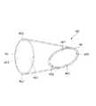
図1は、本発明のカテーテルの第1実施形態を示す縦断面図、図2は、図1に示すカテーテルが備える本発明の造影マーカ(第1実施形態)を示す斜視図、図3は、図2に示す造影マーカを先端側から見た図(正面図)、図4〜図6は、それぞれ、図1に示すカテーテルを製造する工程を順に説明するための図(縦断面図)である。なお、以下では、説明の都合上、図1、図2および図4〜図6中(図7〜図16についても同様)の右側を「基端」、左側を「先端」と言う。<First Embodiment>
1 is a longitudinal sectional view showing a first embodiment of the catheter of the present invention, FIG. 2 is a perspective view showing a contrast marker (first embodiment) of the present invention provided in the catheter shown in FIG. 1, and FIG. 2 is a view (front view) of the contrast marker shown in FIG. 2 as viewed from the distal end side, and FIGS. 4 to 6 are views (longitudinal sectional views) for sequentially explaining the steps of manufacturing the catheter shown in FIG. . In the following description, for convenience of explanation, the right side in FIGS. 1, 2, and 4 to 6 (the same applies to FIGS. 7 to 16) is referred to as “base end”, and the left side is referred to as “tip”.
図1に示すカテーテル1は、可撓性を有するカテーテル本体2と、カテーテル本体2の基端部に接続されたハブ3と、カテーテル本体2の先端部21に埋設された造影マーカ4Cとを備えている。 A catheter 1 shown in FIG. 1 includes a
カテーテル本体2は、長尺なチューブ(中空管)で構成されている。このカテーテル本体2に形成されたルーメン22は、例えば、液体(例えば血液や薬液等)が通過する流路として機能したり、ガイドワイヤが挿通する通路として機能する。 The
カテーテル本体2の先端部21は、その外径が先端方向に向かって漸減するテーパ状をなしている。これにより、先端部21での剛性を、当該先端部21の基端から先端方向に向かって徐々に低減することができる。これにより、カテーテル1は、先端部21で良好な柔軟性を得て、血管への追従性、安全性が向上する。 The
なお、カテーテル本体2の構成材料としては、特に限定されないが、例えば、スチレン系、ポリオレフィン系、ポリウレタン系、ポリエステル系、ポリアミド系、ポリブタジエン系、トランスポリイソプレン系、フッ素ゴム系、塩素化ポリエチレン系等の各種熱可塑性エラストマー等が挙げられ、これらのうちの1種または2種以上を組合せたもの(ポリマーアロイ、ポリマーブレンド、積層体等)を用いることができる。 In addition, although it does not specifically limit as a constituent material of the catheter
また、図1に示すように、カテーテル本体2の外周面23には、親水性材料がコーティングされているのが好ましい。これにより、カテーテル本体2の外周面23に親水性材料で構成されたコート層24が形成される。カテーテル1では、親水性材料が湿潤して潤滑性を生じ、カテーテル1の外周面23の摩擦(摺動抵抗)が低減し、血管等の体腔内や、シース、ガイディングカテーテル等の器具内でカテーテル1の摺動性が向上する。従って、カテーテル1の進退や回転等の操作の際の操作性が向上する。 Moreover, as shown in FIG. 1, it is preferable that the outer
親水性材料としては、例えば、セルロース系高分子物質、ポリエチレンオキサイド系高分子物質、無水マレイン酸系高分子物質(例えば、メチルビニルエーテル−無水マレイン酸共重合体のような無水マレイン酸共重合体)、アクリルアミド系高分子物質(例えば、ポリアクリルアミド、ポリグリシジルメタクリレート−ジメチルアクリルアミド(PGMA−DMAA)のブロック共重合体)、水溶性ナイロン、ポリビニルアルコール、ポリビニルピロリドン等が挙げられる。 Examples of hydrophilic materials include cellulose-based polymer materials, polyethylene oxide-based polymer materials, and maleic anhydride-based polymer materials (for example, maleic anhydride copolymers such as methyl vinyl ether-maleic anhydride copolymer). Acrylamide polymer substances (for example, polyacrylamide, polyglycidyl methacrylate-dimethylacrylamide (PGMA-DMAA) block copolymer), water-soluble nylon, polyvinyl alcohol, polyvinylpyrrolidone and the like.
このような親水性材料は、多くの場合、湿潤(吸水)により潤滑性を発揮し、カテーテルを挿入する血管等の体腔や前記器具の内壁面との摩擦抵抗(摺動抵抗)を低減する。これにより、カテーテルの摺動性が向上し、カテーテル1の操作性がより良好なものとなる。 In many cases, such a hydrophilic material exhibits lubricity by wetting (water absorption), and reduces frictional resistance (sliding resistance) between a body cavity such as a blood vessel into which a catheter is inserted and an inner wall surface of the instrument. Thereby, the slidability of the catheter is improved, and the operability of the catheter 1 becomes better.
カテーテル本体2の基端部には、硬質樹脂材料(例えば、ポリプロピレン)で構成されたハブ3が固定されて(接続されて)いる。ハブ3は、例えば、カテーテル1を操作する際の把持部として機能する部材である。なお、ハブ3のカテーテル本体2に対する固定方法としては、特に限定されず、例えば、融着(熱融着、高周波融着、超音波融着等)、接着(接着剤や溶媒による接着)、嵌合等が挙げられる。 A hub 3 made of a hard resin material (for example, polypropylene) is fixed (connected) to the proximal end portion of the
また、ハブ3は、筒体で構成され、その内腔31がカテーテル本体2のルーメン22と連通している。例えば、カテーテル1にガイドワイヤを挿通させたい場合には、ハブ3の内腔31からガイドワイヤを挿入して、先端方向に向かって送り出すことができる。 The hub 3 is formed of a cylindrical body, and the
図1に示すように、カテーテル本体2の先端部21には、造影マーカ4Cが埋設されている。造影マーカ4Cは、X線不透過性を有するものである。これにより、X線透視下でカテーテル本体2(カテーテル1)の先端部21の位置を把握することができる。なお、造影マーカ4Cを構成するX線不透過性を有する材料としては、特に限定されず、例えば、白金、金、タングステン、タンタル、イリジウム等のような金属材料が挙げられる。 As shown in FIG. 1, a contrast marker 4 </ b> C is embedded in the
図2に示すように、造影マーカ4Cは、前述した金属材料で構成された円筒体(円筒状の部材)を塑性変形させたものである。具体的には、造影マーカ4Cとなる円筒体の先端45をその径方向のうちの一方向(図2中の紙面奥行き方向)に押し潰し、基端46を前記一方向と直交する方向(図2中の上下方向)に押し潰したものである。これにより、図3に示すように、先端45および基端46は、それぞれ、先端側から見たとき(正面視で)の形状が楕円形状となる。 As shown in FIG. 2, the
なお、先端45および基端46に対する押し潰し程度としては、先端45および基端46の短径(内径)がそれぞれ、カテーテル1を製造するときに使用される芯金(マンドレル)8の外径と同等またはそれより若干小さくなる程度であるのが好ましい(図3参照)。これにより、図4〜図6に示すように、造影マーカ4Cに芯金8を挿通した状態で、造影マーカ4Cは、先端45の短径となる部分(以下この部分を「先端内周(第1の当接部)451」と言う)と、基端46の短径となる部分(以下この部分を「基端内周(第2の当接部)461」と言う)とがそれぞれ芯金8の外周面81に当接する。その結果、造影マーカ4Cでは、先端内周451および基端内周461が、芯金8の外周面81に対し、その長手方向の異なる2つの位置で当接するとともに、外周面81の周方向の異なる2つの位置でも当接する。これにより、造影マーカ4Cは、芯金8に対する径方向の位置が規制される、すなわち、センタリングされる。よって、製造されたカテーテル1は、造影マーカ4Cがカテーテル1(カテーテル本体2)と同心的に配置されたものとなる。 In addition, as a degree of crushing with respect to the
次に、カテーテル1を製造する方法(本発明のカテーテルの製造方法)について説明する。図4〜図6に示すように、カテーテル1の製造方法では、芯金(マンドレル)8と金型9とを用いる。 Next, a method for manufacturing the catheter 1 (method for manufacturing the catheter of the present invention) will be described. As shown in FIGS. 4 to 6, the manufacturing method of the catheter 1 uses a
芯金8は、棒状をなす部材であり、その外径が長手方向に沿って一定のものである。また、前述したように、この芯金8の外径は、例えば先端45および基端46の短径のそれぞれの大きさと同等となっている。また、芯金8の外径は、先端45および基端46の長径のそれぞれの大きさよりも小さいことにより、造影マーカ4Cに芯金8を挿通した状態では、芯金8の外周面81と造影マーカ4Cの内周面41との間に間隙(内周側間隙)42aが生じる(形成される)こととなる。 The cored
金型9は、カテーテル本体2の外形形状に対応した円柱状をなすキャビティ91を有している。すなわち、金型9は、キャビティ91を画成する壁部が、カテーテル本体2の先端部21を成形するテーパ部911と、カテーテル本体2の先端部21よりも基端側の部分を成形する内径一定部912とを有している。テーパ部911は、その内径が先端方向に向かって漸減した部分である。このテーパ部911のテーパ角度は、カテーテル本体2の先端部21のテーパ角度と同等である。内径一定部912は、その内径が長手方向に沿って一定の部分である。この内径一定部912の内径は、テーパ部911の最大内径(カテーテル本体2の先端部21よりも基端側の部分の外径)と同等である。 The
また、金型9は、2つの分割半体93a、93bで構成され、型締めと型開きとが自在となっている。なお、金型9は、分割半体93a、93bで構成されているものの他、分割半体93a、93bが分割されずに一体的に形成された1部材で構成されたものであってもよい。 The
また、金型9は、ヒータ92により、キャビティ91内を加熱することができるよう構成されている。 The
このような金型9を用いることにより、カテーテル1を製造する際、カテーテル本体2の外形形状が規制され、よって、所定形状の(図1に示す形状)のカテーテル本体2を得る。 By using such a
図4、図5に示すように、金型9を型締めした際、当該金型9のテーパ部911(キャビティ91を画成する壁部)と造影マーカ4Cの外周面44との間には、間隙(外周側間隙)42bが形成される。 As shown in FIGS. 4 and 5, when the
なお、芯金8および金型9の構成材料としては、特に限定されず、例えば、ステンレス鋼、コバルトニッケル合金等のような耐熱性を有する金属材料が挙げられる。 In addition, it does not specifically limit as a constituent material of the
カテーテル1の製造方法は、部材用意工程(第1の工程)と、部材装着工程(第2の工程)と、部材加熱工程(第3の工程)と、部材冷却工程(第4の工程)と、離型工程(第5の工程)と、コーティング工程(第6の工程)と、ハブ接続工程(第7の工程)とを有している。 The manufacturing method of the catheter 1 includes a member preparation step (first step), a member mounting step (second step), a member heating step (third step), a member cooling step (fourth step), , A mold release step (fifth step), a coating step (sixth step), and a hub connection step (seventh step).
[1] 部材用意工程(第1の工程)
まず、カテーテル本体2となる母材20aと、カテーテル本体2に埋設される造影マーカ4Cと、カテーテル本体2に接続されるハブ3とを用意する。[1] Member preparation process (first process)
First, a
母材20aは、前述したカテーテル本体2についての説明で挙げた樹脂材料で構成されている。図4に示すように、母材20aの形状は、管状をなしている。母材20aの内径は、芯金8の外径よりも若干大きい。これにより、母材20aの内周面201と芯金8の外周面81との間に間隙203aが形成される。また、母材20aの外径は、金型9のテーパ部911の最小内径と最大内径との中間の大きさとなっている。これにより、母材20aの外周面202と金型9のテーパ部911および内径一定部912との間にも、間隙203bが形成される。 The
[2] 部材装着工程(第2の工程)
次に、母材20aと造影マーカ4Cとに芯金8を挿通する(以下この状態を「挿通状態」と言う)。このとき、造影マーカ4Cを母材20aよりも先端側に位置させる。[2] Member mounting process (second process)
Next, the
そして、型開き状態の金型9の内側に、すなわち、型開き状態の分割半体93aと分割半体93bとの間に、挿通状態の母材20aおよび造影マーカ4Cを配置する。その後、型締めをして、芯金8ごと母材20aおよび造影マーカ4Cを金型9のキャビティ91内に収納する。また、このとき、図4に示すように、造影マーカ4Cは、その先端縁部43が金型9のテーパ部911に当接しない程度に位置決めされている(プレ位置決め)。 Then, the
[3] 部材加熱工程(第3の工程)
次に、図4に示す状態から、圧縮手段(図示せず)で母材20aを先端方向に向かって圧縮するとともに、ヒータ92で当該母材20aと芯金8とを金型9ごと加熱する(図5参照)。これにより、母材20aが溶融され、当該溶融した母材20aは、先端方向および径方向に向かって流れることとなる(図5参照)。この溶融した母材20aにより、造影マーカ4Cは、先端方向に向かって押圧されて、先端縁部43(先端45)が金型9のテーパ部911の途中に当接するまで移動する(前進する)。そして、造影マーカ4Cの先端縁部43が金型9のテーパ部911に当接した際には、金型9に対する造影マーカ4Cの長手方向の位置決めがなされる(本位置決め)。[3] Member heating step (third step)
Next, from the state shown in FIG. 4, the
また、前述したように、造影マーカ4Cは、図2に示す形状をなしている。これにより、図4、図5に示す挿通状態では、先端45の長径となる部分452から基端内周461に渡って、間隙42aは、その間隙距離が先端方向に向かって漸増した部分を有し、間隙42bは、その間隙距離が基端方向に向かって漸増した部分を有する。また、同様に挿通状態では、先端内周451から基端46の長径となる部分462に渡って、間隙42aは、その間隙距離が基端方向に向かって漸増した部分を有し、間隙42bは、その間隙距離が先端方向に向かって漸増した部分を有する。 Further, as described above, the
そして、溶融した母材20aで、間隙42a、42b、203a、203bがそれぞれ満たされる。これにより、キャビティ91内全体が溶融した母材20aで満たされる。 Then, the
特に、溶融した母材20aで間隙42a、42bがそれぞれ満たされることにより、当該溶融した母材20aで造影マーカ4Cのほとんどの部分(ほぼ全体)を囲むことができる。これにより、造影マーカ4Cが確実に埋設されたカテーテル1(カテーテル本体2)を得ることができる。 In particular, when the
[4] 部材冷却工程(第4の工程)
次に、図6に示す状態からヒータ92の作動を停止し、溶融した母材20aを冷却する。これにより、溶融した母材20aが固化(凝固)して、カテーテル本体2が成形される。なお、このときの冷却方法としては、特に限定されないが、自然に放熱させる自然冷却による方法や、母材20aから人工的に熱を奪う強制冷却による方法等が挙げられる。[4] Member cooling step (fourth step)
Next, the operation of the
[5] 離型工程(第5の工程)
次に、金型9を型開きして、金型9からカテーテル本体2を芯金8ごと取り出す。その後、カテーテル本体2から芯金8を抜去する。[5] Mold release step (fifth step)
Next, the
[6] コーティング工程(第6の工程)
次に、カテーテル本体2の外周面23に前述した親水性材料を塗布する。なお、この塗布方法としては、特に限定されないが、例えば、ディッピングによる方法、スプレーによる方法等が挙げられる。[6] Coating process (sixth process)
Next, the hydrophilic material described above is applied to the outer
その後、前記塗布された親水性材料を乾燥させる。これにより、カテーテル本体2の外周面23にコート層24が形成される。なお、このときの乾燥方法としては、特に限定されないが、例えば、加熱による方法、風を当てる方法等が挙げられる。 Thereafter, the applied hydrophilic material is dried. Thereby, the
[7] ハブ接続工程(第7の工程)
次に、前記部材用意工程で用意したハブ3を、カテーテル本体2の基端部に接続し、前述した固定方法により固定する。[7] Hub connection process (seventh process)
Next, the hub 3 prepared in the member preparing step is connected to the proximal end portion of the
以上のような工程を経ることにより、図1に示すカテーテル1が得られる。
カテーテル1では、その製造過程で造影マーカ4Cが、溶融した母材20aで囲まれるので、母材20a(カテーテル本体2)内に造影マーカ4Cを容易に埋設することができる。そして、得られたカテーテル1の造影マーカ4Cでは、先端45(先端縁部43の部分452の外側に対応する部分)が金型9のテーパ部911の内表面の途中に当接して当接部を形成し、基端46の基端内周461が芯金8の外周面81に当接して当接部を形成する。その結果、各当接部は、それぞれ、成形されたカテーテル本体2の外周面23および内周面25にわずかに露出する。すなわち、造影マーカ4Cのうちカテーテル本体2の外周面23に露出するのは、前者の当接部(先端45)のみであり、カテーテル本体2の内周面25に露出するのは、後者の当接部(基端内周461)のみとなる。わずかに外周面23および内周面25に露出する造影マーカ4Cの各当接部以外の部分は、カテーテル本体2内部に確実に埋設される。The catheter 1 shown in FIG. 1 is obtained through the above steps.
In the catheter 1, since the
このように、造影マーカ4Cには露出部が形成されているが、その存在領域(大きさ)は極めて微小である。これにより、カテーテル1の内周面25および外周面23に当該露出部によって段差部が生じたとしてもそれは無視することができる程度のものとなり、よって、当該内周面25および外周面23が平滑なものとなる。 Thus, although the exposed part is formed in the
また、前述したように、先端45および基端46は、それぞれ、先端側から見たときの形状が楕円形状となっている。換言すれば、造影マーカ4Cを先端内周451および基端内周461が位置する箇所でそれぞれ切断したときの当該造影マーカ4Cの横断面形状は、楕円形をなしている。このような形状をなしていることにより、例えば、カテーテル1を製造する際に、金型9内に造影マーカ4Cよりも先端側にさらにカテーテル本体2の一部(先端部21)となる第2の母材(図示せず)を配置した場合、母材20aが溶融されると、当該溶融した母材20aは、造影マーカ4C内よりも外周側に優先的に流れ込む。また、前記第2の母材も溶融され、当該溶融した第2の母材は、造影マーカ4Cの外周よりも内側へ優先的に流れ込む。このように、造影マーカ4Cを介して、母材20aで構成された部分と第2の母材で構成された部分とが形成される。 Further, as described above, the
<第2実施形態>
図7は、本発明のカテーテルが備える造影マーカ(第2実施形態)を示す斜視図である。Second Embodiment
FIG. 7 is a perspective view showing a contrast marker (second embodiment) provided in the catheter of the present invention.
以下、この図を参照して本発明の造影マーカおよびカテーテルの第2実施形態について説明するが、前述した実施形態との相違点を中心に説明し、同様の事項はその説明を省略する。
本実施形態は、造影マーカの形状が異なること以外は前記第1実施形態と同様である。Hereinafter, the second embodiment of the contrast marker and catheter of the present invention will be described with reference to this figure, but the description will focus on the differences from the above-described embodiment, and the description of the same matters will be omitted.
This embodiment is the same as the first embodiment except that the shape of the contrast marker is different.
図7に示す造影マーカ4Dは、造影マーカ4Dとなる円筒体の先端45をその径方向のうちの一方向(図7中の左右方向)に押し潰し、基端46を前記一方向と直交する以外の方向(前記一方向と異なる方向)に押し潰したものである。 The
このような造影マーカ4Dでも、前記第2実施形態の造影マーカ4Cと同様に、先端内周451および基端内周461が、芯金8の外周面81に対し、その長手方向の異なる2つの位置で当接するとともに、外周面81の周方向の異なる2つの位置でも当接する。これにより、造影マーカ4Dは、芯金8に対する径方向の位置が規制される、すなわち、センタリングされる。 Even in such a
また、このように位置が規制された造影マーカ4Dは、記第2実施形態の造影マーカ4Cと同様に、溶融した母材20aで囲まれるので、母材20a内に造影マーカ4Dを容易に埋設することができる。そして、造影マーカ4Dでは、先端45(先端縁部43の部分452の外側に対応する部分)が金型9のテーパ部911の内表面の途中に当接して当接部を形成し、基端46の基端内周461が芯金8の外周面81に当接して当接部を形成する。その結果、各当接部は、それぞれ、成形されたカテーテル本体2の外周面23および内周面25にわずかに露出する。すなわち、造影マーカ4Dのうちカテーテル本体2の外周面23に露出するのは、前者の当接部(先端45)のみであり、カテーテル本体2の内周面25に露出するのは、後者の当接部(基端内周461)のみとなる。わずかに外周面23および内周面25に露出する造影マーカ4Dの各当接部以外の部分は、カテーテル本体2内部に確実に埋設される。 Further, the
このように、造影マーカ4Dには露出部が形成されているが、その存在領域は極めて微小である。これにより、カテーテル1の内周面25および外周面23に当該露出部によって段差部が生じたとしてもそれは無視することができる程度のものとなり、よって、当該内周面25および外周面23が平滑なものとなる。 Thus, although the exposed part is formed in the
<第3実施形態>
図8は、本発明のカテーテルが備える造影マーカ(第3実施形態)を示す斜視図、図9は、図8に示す造影マーカに芯金を挿通した状態を示す縦断面図である。<Third Embodiment>
FIG. 8 is a perspective view showing a contrast marker (third embodiment) provided in the catheter of the present invention, and FIG. 9 is a longitudinal sectional view showing a state where a cored bar is inserted through the contrast marker shown in FIG.
以下、これらの図を参照して本発明の造影マーカおよびカテーテルの第3実施形態について説明するが、前述した実施形態との相違点を中心に説明し、同様の事項はその説明を省略する。
本実施形態は、造影マーカの形状が異なること以外は前記第1実施形態と同様である。Hereinafter, the third embodiment of the contrast marker and the catheter of the present invention will be described with reference to these drawings. However, the difference from the above-described embodiment will be mainly described, and the description of the same matters will be omitted.
This embodiment is the same as the first embodiment except that the shape of the contrast marker is different.
図8に示す造影マーカ4Eは、造影マーカ4Eとなる円筒体の長手方向の途中の第1の部分47をその径方向のうちの一方向(図8中の上下方向)に押し潰し、第1の部分47よりも基端側の第2の部分48を前記一方向と直交する方向(図8中の紙面奥行き方向)に押し潰したものである。第1の部分47および第2の部分48では、それぞれ、造影マーカ4Eの外周面44は、凹状をなす。 The
なお、第1の部分47および第2の部分48に対する押し潰し程度としては、第1の部分47および第2の部分48の内径がそれぞれ芯金8の外径と同等またはそれより若干小さくなる程度であるのが好ましい。これにより、図9に示す挿通状態で、造影マーカ4Eは、その内周面41の第1の部分47に対応する部分(以下この部分を「第1の当接部411」と言う)と、内周面41の第2の部分48に対応する部分(以下この部分を「第2の当接部412」と言う)とがそれぞれ芯金8の外周面81に当接する。その結果、造影マーカ4Eでは、第1の当接部411および第2の当接部412が、芯金8の外周面81に対し、その長手方向の異なる2つの位置で当接するとともに、外周面81の周方向の異なる2つの位置でも当接する。これにより、造影マーカ4Eは、芯金8に対する径方向の位置が規制される、すなわち、センタリングされる。 The degree of crushing of the
また、造影マーカ4Eを第1の当接部411および第2の当接部412が位置する箇所でそれぞれ切断したときの造影マーカ4Eの横断面形状は、その各当接部に対応する部分が直線状をなしている。これにより、第1の当接部411および第2の当接部412が芯金8の外周面81に確実に(好適に)接することができ、よって、確実にセンタリングされる。 Further, the cross-sectional shape of the
造影マーカ4Eの当接部(第1の当接部411、第2の当接部412)は成形されたカテーテル本体2の内周面41にわずかに露出する。すなわち、造影マーカ4Eのうちカテーテル本体2の内周面41に露出するのは当接部(第1の当接部411、第2の当接部412)のみとなる。わずかに内周面41に露出する造影マーカ4Eの各当接部以外の部分は、カテーテル本体2内部に確実に埋設される。 The contact portions (
また、造影マーカ4Eは、円筒体の一部を塑性変形させたものであるため、全体としては筒状が維持されている。これにより、カテーテル1を製造する際、溶融した母材20aが造影マーカ4E内に円滑に(迅速に)入り込むことができる。 Further, since the
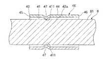
<第4実施形態>
図10は、本発明のカテーテルが備える造影マーカ(第4実施形態)を示す縦断面図(本発明のカテーテルを製造する工程を説明するための図)である。<Fourth embodiment>
FIG. 10 is a longitudinal sectional view (a diagram for explaining a process of manufacturing the catheter of the present invention) showing a contrast marker (fourth embodiment) provided in the catheter of the present invention.
以下、この図を参照して本発明の造影マーカおよびカテーテルの第4実施形態について説明するが、前述した実施形態との相違点を中心に説明し、同様の事項はその説明を省略する。
本実施形態は、造影マーカの形状が異なること以外は前記第1実施形態と同様である。Hereinafter, the contrast marker and the catheter according to the fourth embodiment of the present invention will be described with reference to this figure. However, the difference from the above-described embodiment will be mainly described, and the description of the same matters will be omitted.
This embodiment is the same as the first embodiment except that the shape of the contrast marker is different.
図10に示すように、造影マーカ4Fは、その外周面44に途中が外方に向かって突出した3つ以上(図10中ではそれらのうちの2つが示されている)の突出部441を有している。これらの突出部441は、造影マーカ4Fの中心軸回りに等角度間隔に配置されている。そして、各突出部441は、それぞれ、造影マーカ4Fが金型9内で母材20aにより先端方向に向かって押圧された際、金型9のテーパ部911の途中に当接する。これにより、造影マーカ4Fは、金型9に対しその長手方向および径方向の位置決めがなされる。各突出部441は、それぞれ、造影マーカ4Fの長手方向先端から一定の距離にある。すなわち、各突出部441は、それぞれ、造影マーカ4Fの長手方向の先端から一定の距離で金型9に当接する。 As shown in FIG. 10, the contrast marker 4 </ b> F has three or more projecting portions 441 (two of them are shown in FIG. 10) projecting outward on the outer
そして、この位置決めがなれた状態で、前述したように母材20aを加熱することにより、母材20aが溶融され、当該溶融した母材20aで、間隙42a、42b、203a、203bがそれぞれ満たされる。その後、溶融した母材20aを冷却することにより、造影マーカ4Fが埋設されたカテーテル本体2を得る。 Then, in the state where the positioning is completed, the
造影マーカ4Fの当接部(突出部441)は、成形されたカテーテル本体2の外周面44にわずかに露出する。すなわち、造影マーカ4Fのうちカテーテル本体2の外表面に露出するのは当接部(突出部441)のみとなる。わずかに外周面44に露出する造影マーカ4Fの当接部以外の部分は、カテーテル本体2内部に確実に埋設される。 The contact portion (projecting portion 441) of the
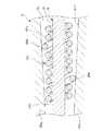
<第5実施形態>
図11は、本発明のカテーテルが備える造影マーカ(第5実施形態)を示す縦断面図(本発明のカテーテルを製造する工程を説明するための図)である。<Fifth Embodiment>
FIG. 11 is a longitudinal sectional view (a diagram for explaining a process of manufacturing the catheter of the present invention) showing a contrast marker (fifth embodiment) included in the catheter of the present invention.
以下、この図を参照して本発明の造影マーカおよびカテーテルの第5実施形態について説明するが、前述した実施形態との相違点を中心に説明し、同様の事項はその説明を省略する。 Hereinafter, the fifth embodiment of the contrast marker and catheter of the present invention will be described with reference to this figure, but the description will focus on the differences from the above-described embodiment, and the description of the same matters will be omitted.
本実施形態は、造影マーカの構成(形状)が異なること以外は前記第1実施形態と同様である。 This embodiment is the same as the first embodiment except that the configuration (shape) of the contrast marker is different.
図11に示すように、造影マーカ4Gは、線状体をコイル状(パイプ状)に巻回して形成されたものである。そして、造影マーカ4Gは、隣接する線状体同士が離間した疎巻き状態となっている。 As shown in FIG. 11, the
この造影マーカ4Gは、線状体の途中の2箇所が外方に向かって突出した第1の突出部49aと第2の突出部49bとが形成されている。造影マーカ4Gでは、第1の突出部49aと第2の突出部49bとは、金型9のテーパ部911に対し、その長手方向の異なる2つの位置で当接するとともに、周方向の異なる2つの位置でも当接する。これにより、造影マーカ4Gは、金型9に対しその長手方向および径方向の位置が確実に規制される、すなわち、センタリングされる。 The
そして、このセンタリング状態で、前述したように母材20aを加熱することにより、母材20aが溶融され、当該溶融した母材20aで、間隙42a、42bがそれぞれ満たされる。その後、溶融した母材20aを冷却することにより、造影マーカ4Gが埋設されたカテーテル本体2を得る。 In this centering state, the
なお、造影マーカ4Gは、図11に示す構成では隣接する線状体同士が離間した疎巻き状態のものであるが、これに限定されず、例えば、隣接する線状体同士が当接した密巻き状態のものであってもよい。 In the configuration shown in FIG. 11, the
また、造影マーカ4Gは、その線状体の一部が芯金8の外周面81に当接する少なくとも1つの当接部をさらに有していてもよい。これにより、造影マーカ4Gは、芯金8に対する径方向の位置がより確実に規制される、すなわち、センタリングされる。 The
造影マーカ4Gの当接部(第1の突出部49aおよび第2の突出部49b)は、成形されたカテーテル本体2の外周面23にわずかに露出する。すなわち、造影マーカ4Gのうちカテーテル本体2の外周面23に露出するのは当接部(第1の突出部49aおよび第2の突出部49b)のみとなる。また線状体の一部が芯金8の外周面81に当接して当接部を有する場合、この当接部は、成形されたカテーテル本体2の内周面25にわずかに露出する。すなわち、造影マーカ4Gのうちカテーテル本体2の内周面25に露出するのはこの当接部(図示せず)のみとなる。わずかに外周面23(および内周面25)に露出する造影マーカ4Gの当接部以外の部分は、カテーテル本体2内部に確実に埋設される。 The contact portions (
<第6実施形態>
図12は、本発明のカテーテルが備える造影マーカ(第6実施形態)を示す縦断面図(本発明のカテーテルを製造する工程を説明するための図)である。<Sixth Embodiment>
FIG. 12 is a longitudinal sectional view (a diagram for explaining a process of manufacturing the catheter of the present invention) showing a contrast marker (sixth embodiment) included in the catheter of the present invention.
以下、この図を参照して本発明の造影マーカおよびカテーテルの第6実施形態について説明するが、前述した実施形態との相違点を中心に説明し、同様の事項はその説明を省略する。
本実施形態は、造影マーカの形状が異なること以外は前記第5実施形態と同様である。Hereinafter, the sixth embodiment of the contrast marker and catheter of the present invention will be described with reference to this figure, but the description will focus on differences from the above-described embodiment, and the description of the same matters will be omitted.
This embodiment is the same as the fifth embodiment except that the shape of the contrast marker is different.
図12に示すように、造影マーカ4Hは、線状体の途中2箇所で、その線径が増大した(変化した)ものである。線径が増大した各部分(以下「第1の大径部50a」、「第2の大径部50b」と言う)は、造影マーカ4Hの途中が外方に向かって突出した部分となっている。 As shown in FIG. 12, the contrast marker 4H has an increased (changed) wire diameter at two points along the linear body. Each portion with the increased wire diameter (hereinafter referred to as “first
造影マーカ4Hでは、第1の大径部50aと第2の大径部50bとは、金型9のテーパ部911に対し、その長手方向の異なる2つの位置で当接するとともに、周方向の異なる2つの位置でも当接する。これにより、造影マーカ4Hは、金型9に対し長手方向および径方向の位置が規制される、すなわち、センタリングされる。 In the contrast marker 4H, the first large-
そして、このセンタリング状態で、前述したように母材20aを加熱することにより、母材20aが溶融され、当該溶融した母材20aで、間隙42a、42bがそれぞれ満たされる。その後、溶融した母材20aを冷却することにより、造影マーカ4Hが埋設されたカテーテル本体2を得る。 In this centering state, the
なお、造影マーカ4Hは、図12に示す構成では隣接する線状体同士が離間した疎巻き状態のものであるが、これに限定されず、例えば、隣接する線状体同士が当接した密巻き状態のものであってもよい。 In the configuration shown in FIG. 12, the contrast marker 4H is in a loosely wound state in which adjacent linear bodies are separated from each other. However, the present invention is not limited to this, and for example, the dense marker in which adjacent linear bodies are in contact with each other. It may be wound.
また、造影マーカ4Hをなす線状体の線径が増大した部分(第1の大径部50aと第2の大径部50b)が内方に向かって突出していてもよい。造影マーカ4Hでは、第1の大径部50aと第2の大径部50bとは、芯金8に対し、その長手方向の異なる位置2つの位置で当接するとともに、周方向の異なる2つの位置でも当接する。これにより、造影マーカ4Hは、芯金8に対する径方向の位置が規制される、すなわち、センタリングされる。 Moreover, the part (the 1st
造影マーカ4Hの当接部(第1の大径部50aと第2の大径部50b)は、成形されたカテーテル本体2の外表面にわずかに露出する。すなわち、造影マーカ4Hのうちカテーテル本体2の外表面に露出するのは当接部(第1の大径部50aと第2の大径部50b)のみとなる。また、線状体の一部が芯金8の外周面23に当接して当接部を有する場合、この当接部は、成形されたカテーテル本体2の内周面25にわずかに露出する。すなわち、造影マーカ4Hのうちカテーテル本体2の内周面25に露出するのは当接部(図示せず)のみとなる。わずかに外周面23(および内周面25)に露出する造影マーカ4Hの当接部以外の部分は、カテーテル本体2内部に確実に埋設される。 The contact portions (the first
<第7実施形態>
図13は、本発明のカテーテルが備える造影マーカ(第7実施形態)を示す縦断面図(本発明のカテーテルを製造する工程を説明するための図)である。<Seventh embodiment>
FIG. 13: is a longitudinal cross-sectional view (The figure for demonstrating the process of manufacturing the catheter of this invention) which shows the contrast marker (7th Embodiment) with which the catheter of this invention is provided.
以下、この図を参照して本発明の造影マーカおよびカテーテルの第7実施形態について説明するが、前述した実施形態との相違点を中心に説明し、同様の事項はその説明を省略する。
本実施形態は、造影マーカの形状が異なること以外は前記第5実施形態と同様である。Hereinafter, the seventh embodiment of the contrast marker and catheter of the present invention will be described with reference to this figure, but the description will focus on the differences from the above-described embodiment, and the description of the same matters will be omitted.
This embodiment is the same as the fifth embodiment except that the shape of the contrast marker is different.
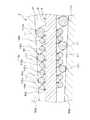
図13に示すように、造影マーカ4iは、線状体をコイル状(パイプ状)に巻回して形成されたものである。そして、造影マーカ4iは、隣接する線状体同士が離間した疎巻き状態になっていてもよく、密着巻きになっていてもよい。 As shown in FIG. 13, the contrast marker 4i is formed by winding a linear body into a coil shape (pipe shape). The contrast marker 4i may be in a loosely wound state in which adjacent linear bodies are separated from each other, or may be closely wound.
この造影マーカ4iは、3条巻きであって、3本の線状体が同じ方向に巻かれているものである。すなわち、別々の(独立した)3本の線状体100a、100b、100cから形成される(構成されている)。このような複数の線状体を含む多条コイルは、線状体同士の摩擦抵抗があるため、1本の線状体からなるコイルより縦方向(長手方向)に伸びにくくかつ柔軟性を持っている。図13に示すように、線状体100aは他の線状体100b、100cよりもコイルの巻回の外径が大きく形成されている。これにより、造影マーカ4iは、線状体100aが金型9のテーパ部911(内表面)の途中にその周方向および径方向の2箇所以上で当接し、よって金型9に対する造影マーカ4iの長手方向および径方向の位置が規制される、すなわちセンタリングされる。 The contrast marker 4i is a three-strand winding in which three linear bodies are wound in the same direction. That is, it is formed (configured) from three separate (independent)
なお、造影マーカ4iの線状体100aの複数のコイルの巻回の外径は、金型9のテーパ部911の内径の変化に対応して先端部から基端部に向けて増大するように形成されていてもよい。これにより、造影マーカ4iは、金型9のテーパ部911と当接する複数の当接部101を確実に有することとなり、より確実にセンタリングされる。 Note that the outer diameter of the winding of the plurality of coils of the
造影マーカ4iの各当接部101は、それぞれ、成形されたカテーテル本体2の外周面23にわずかに露出する。すなわち、造影マーカ4iのうちカテーテル本体2の外周面23に露出するのは各当接部101のみとなる。わずかに外周面23に露出する造影マーカ4iの当接部101以外の部分はカテーテル本体2内部に確実に埋設される。 Each
センタリング状態で、前述したように母材20aを加熱することにより、母材20aが溶融され、当該溶融した母材20aで、間隙42a、42bがそれぞれ満たされる。その後、溶融した母材aを冷却することにより、造影マーカ4iが埋設されたカテーテル本体2を得る。 When the
なお、造影マーカ4iを構成する線状体は多条巻きであればよく、特に2〜5条巻きが好ましい。多条コイルの両端がほつれる可能性がある場合は、両端を半田付けやろう付け等で固定してもよい。 In addition, the linear body which comprises the contrast marker 4i should just be multi-strand winding, and 2-5 strip winding is especially preferable. When there is a possibility that both ends of the multi-strand coil are frayed, both ends may be fixed by soldering or brazing.
<第8実施形態>
図14は、本発明のカテーテルが備える造影マーカ(第8実施形態)を示す縦断面図(本発明のカテーテルを製造する工程を説明するための図)である。<Eighth Embodiment>
FIG. 14 is a longitudinal sectional view (a diagram for explaining a process of manufacturing the catheter of the present invention) showing a contrast marker (eighth embodiment) included in the catheter of the present invention.
以下、この図を参照して本発明の造影マーカおよびカテーテルの第8実施形態について説明するが、前述した実施形態との相違点を中心に説明し、同様の事項はその説明を省略する。 Hereinafter, the eighth embodiment of the contrast marker and catheter of the present invention will be described with reference to this figure, but the description will focus on differences from the above-described embodiment, and the description of the same matters will be omitted.
本実施形態は、造影マーカを構成する複数の線状体のうちの1本の線状体の内径の大きさが異なること以外は前記第7実施形態と同様である。 The present embodiment is the same as the seventh embodiment except that the size of the inner diameter of one of the plurality of linear bodies constituting the contrast marker is different.
図14に示すように、造影マーカ4Jでは、線状体100cのコイルの巻回の内径が芯金8の外径と同等またはそれより若干小さくなる程度に形成されている。従って、造影マーカ4Jは、線状体100aのコイルの巻回の外径を大きくして金型9のテーパ部911の内表面に当接させ、同時に線状体100cのコイルの巻回の内径を小さくして芯金8の外周面81に当接させるように設定されたものとなる。これにより、造影マーカ4Jは金型9に対する長手方向および径方向の位置が規制されると共に、芯金8に対する径方向の位置が規制される。 As shown in FIG. 14, the contrast marker 4 </ b> J is formed so that the inner diameter of the coil of the
なお、造影マーカ4Jの線状体100aの複数のコイルの巻回の外径は、金型9のテーパ部911の内径の変化に対応して先端部から基端部に向けて増大するように形成されていてもよい。それにより造影マーカ4Jと金型9のテーパ部911が複数の当接部101を有することとなり、より確実にセンタリングされる。 Note that the outer diameter of the winding of the plurality of coils of the
造影マーカ4Jの当接部101は、成形されたカテーテル本体2の外周面23にわずかに露出する。すなわち、造影マーカ4Jのうちカテーテル本体2の外周面23に露出するのは当接部101のみとなる。また、線状体の一部が芯金8の外周面81に当接して当接部102を有するため、この当接部102は、成形されたカテーテル本体2の内周面25にわずかに露出する。すなわち、造影マーカ4Jのうちカテーテル本体2の外周面23に露出するのは当接部102のみとなる。わずかに外周面23および外周面23に露出する造影マーカ4Jの当接部101、102以外の部分は、カテーテル本体2内部に確実に埋設される。 The
センタリング状態で、前述したように母材20aを加熱することにより、母材20aが溶融され、当該溶融した母材20aで、間隙42a、42bがそれぞれ満たされる。その後、溶融した母材aを冷却することにより、造影マーカ4Jが埋設されたカテーテル本体2を得る。 When the
なお、造影マーカ4Jを構成する線状体は多条巻きであればよく、特に2〜5条巻きが好ましい。多条コイルの両端がほつれる可能性がある場合は、両端を半田付けやろう付け等で固定してもよい。 In addition, the linear body which comprises the
<第9実施形態>
図15は、本発明のカテーテルが備える造影マーカ(第9実施形態)を示す縦断面図(本発明のカテーテルを製造する工程を説明するための図)である。<Ninth Embodiment>
FIG. 15 is a longitudinal sectional view (a diagram for explaining a process of manufacturing the catheter of the present invention) showing a contrast marker (9th embodiment) provided in the catheter of the present invention.
以下、この図を参照して本発明の造影マーカおよびカテーテルの第9実施形態について説明するが、前述した実施形態との相違点を中心に説明し、同様の事項はその説明を省略する。
本実施形態は、造影マーカの形状が異なること以外は前記第7実施形態と同様である。Hereinafter, the ninth embodiment of the contrast marker and catheter of the present invention will be described with reference to this figure, but the description will focus on the differences from the above-described embodiment, and description of similar matters will be omitted.
This embodiment is the same as the seventh embodiment except that the shape of the contrast marker is different.
図15に示すように、造影マーカ4Kは、線状体をコイル状(パイプ状)に巻回して形成されたものである。そして、造影マーカ4Kは、隣接する線状体同士が離間した疎巻き状態になっていてもよく、密着巻きになっていてもよい。 As shown in FIG. 15, the
この造影マーカ4Kは、3条巻きであって、3本の線状体が同じ方向に巻かれているものである。すなわち、別々の3本の線状体110a、110b、110cから形成されて(構成されて)いる。ここで線状体110aのみ線径が増大されて形成されている。これにより、造影マーカ4Kの線状体110aのコイル巻回の外径が大きくなり、金型9のテーパ部911の内表面の途中にその長手方向および径方向に複数の箇所で当接する。よって、金型9に対する造影マーカ4Kの長手方向および径方向の位置が規制される、すなわち、センタリングされる。 This
なお、造影マーカ4Kの線状体110aの線径は、金型9のテーパ部911の内径の変化に対応して先端部から基端部に向けて増大するように形成されている。これにより、造影マーカ4Kは、金型9のテーパ部911と当接する当接部111を確実に複数有することとなり、より確実にセンタリングされる。 The diameter of the
造影マーカ4Kの当接部111は、形成されたカテーテル本体2の外周面23にわずかに露出する。すなわち、造影マーカ4Kのうちカテーテル本体2の外周面23に露出するのは当接部111のみとなる。わずかに外周面23に露出する造影マーカ4Kの当接部111以外の部分は、カテーテル本体2内部に確実に埋設される。 The
そして、センタリング状態で、前述したように母材20aを加熱することにより、母材20aが溶融され、当該溶融した母材20aで、間隙42a、42bがそれぞれ満たされる。その後、溶融した母材aを冷却することにより、造影マーカ4Kが埋設されたカテーテル本体2を得る。 Then, by heating the
また、このように造影マーカ4Kの線状体の線径を増大させることで造影性能が向上する。 Further, the contrast performance is improved by increasing the diameter of the linear body of the
<第10実施形態>
図16は、本発明のカテーテルが備える造影マーカ(第10実施形態)を示す縦断面図(本発明のカテーテルを製造する工程を説明するための図)である。<Tenth Embodiment>
FIG. 16 is a longitudinal sectional view (a diagram for explaining a process of manufacturing the catheter of the present invention) showing a contrast marker (tenth embodiment) included in the catheter of the present invention.
以下、この図を参照して本発明の造影マーカおよびカテーテルの第10実施形態について説明するが、前述した実施形態との相違点を中心に説明し、同様の事項はその説明を省略する。 Hereinafter, the tenth embodiment of the contrast marker and catheter of the present invention will be described with reference to this figure, but the description will focus on the differences from the above-described embodiment, and the description of the same matters will be omitted.
本実施形態は、造影マーカを構成する複数の線状体のうちの1本の線状体の内径の大きさが異なること以外は前記第9実施形態と同様である。 The present embodiment is the same as the ninth embodiment except that one of the plurality of linear bodies constituting the contrast marker has a different inner diameter.
図16に示すように、造影マーカ4Lでは、線状体110cの線径を増大させることにより、コイル巻回の内径が芯金8の外径と同等またはそれより若干小さくなる程度となっている。そして、造影マーカ4Lの線状体110aの線径を増大させることにより、コイル巻回の外径を大きくして金型9のテーパ部911の内表面に当接させ、同時に線状体110cの線径を増大させることにより、コイル巻回の内径を小さくして、芯金8の外周面81に当接させるように設定されている。これにより、造影マーカ4Lは、金型9に対する長手方向および径方向の位置が規制されると共に、芯金8に対する径方向の位置が規制される。 As shown in FIG. 16, in the
なお、造影マーカ4Lの線状体110aの線径は、金型9のテーパ部911の内径の変化に対応して先端部から基端部に向けて増大するように形成されている。これにより、造影マーカ4Lは、金型9のテーパ部911と当接する当接部111を確実に複数有することとなり、より確実にセンタリングされる。 In addition, the wire diameter of the
造影マーカ4Lの当接部111は、形成されたカテーテル本体2の外周面23にわずかに露出する。すなわち、造影マーカ4Lのうちカテーテル本体2の外周面23に露出するのは当接部111のみとなる。また、線状体の一部が芯金8の外周面81に当接して当接部112を有するため、この当接部112は、成形されたカテーテル本体2の外周面23にわずかに露出する。すなわち、造影マーカ4Lのうちカテーテル本体2の内周面25に露出するのは当接部112のみとなる。わずかに外周面23および外周面23に露出する造影マーカ4Lの当接部111、112以外の部分は、カテーテル本体2内部に確実に埋設される。 The
そして、センタリング状態で、前述したように母材20aを加熱することにより、母材20aが溶融され、当該溶融した母材20aで、間隙42a、42bがそれぞれ満たされる。その後、溶融した母材aを冷却することにより、造影マーカ4Lが埋設されたカテーテル本体2を得る。 Then, by heating the
また、このように造影マーカ4Lの線状体の線径を増大させることで造影性能が向上する。 Further, the contrast performance is improved by increasing the diameter of the linear body of the
以上、本発明の造影マーカおよびカテーテルを図示の実施形態について説明したが、本発明は、これに限定されるものではなく、造影マーカおよびカテーテルを構成する各部は、同様の機能を発揮し得る任意の構成のものと置換することができる。また、任意の構成物が付加されていてもよい。 As mentioned above, although the illustrated embodiment of the contrast marker and the catheter of the present invention has been described, the present invention is not limited to this, and each part constituting the contrast marker and the catheter is an arbitrary one that can exhibit the same function. It can be replaced with the configuration of Moreover, arbitrary components may be added.
また、本発明の造影マーカおよびカテーテルは、前記各実施形態のうちの、任意の2以上の構成(特徴)を組み合わせたものであってもよい。 In addition, the contrast marker and catheter of the present invention may be a combination of any two or more configurations (features) of the above embodiments.
また、造影マーカには、スリットが形成されていてもよい。
また、カテーテルでは、コート層を省略することができる。Moreover, the slit may be formed in the contrast marker.
In the catheter, the coat layer can be omitted.
1 カテーテル
2 カテーテル本体
20a 母材
201 内周面
202 外周面
203a、203b 間隙
21 先端部
22 ルーメン
23 外周面
24 コート層
25 内周面
3 ハブ
31 内腔
4C、4D、4E、4F、4G、4H、4i、4J、4K、4L 造影マーカ
41 内周面
411 第1の当接部
412 第2の当接部
42a 間隙(内周側間隙)
42b 間隙(外周側間隙)
43 先端縁部
44 外周面
441 突出部
45 先端
451 先端内周(第1の当接部)
452 部分
46 基端
461 基端内周(第2の当接部)
462 部分
47 第1の部分
48 第2の部分
49a 第1の突出部
49b 第2の突出部
50a 第1の大径部
50b 第2の大径部
100a、100b、100c 線状体
101、102 当接部
110a、110b、110c 線状体
111、112 当接部
8 芯金(マンドレル)
81 外周面
9 金型
91 キャビティ
911 テーパ部
912 内径一定部
92 ヒータ
93a、93b 分割半体DESCRIPTION OF SYMBOLS 1
42b Gap (outer peripheral side gap)
43
452
462
81
Claims (5)
Translated fromJapanese前記カテーテルの外周面の周方向の異なる少なくとも2箇所で当該造影マーカの外周面の一部が露出しているか、または、前記カテーテルの内周面の周方向の異なる少なくとも2箇所で当該造影マーカの内周面の一部が露出した露出部と、
当該造影マーカの前記露出部以外の残りの部分が、前記筒体の内周部側と外周部側とから囲まれるように前記カテーテルに埋設された埋設部とを有し、
当該造影マーカを前記露出部が位置する箇所で切断したときの当該造影マーカの横断面形状は、楕円形をなすことを特徴とする造影マーカ。Contrast marker composed of acylindrical body that can grasp the position of the tip of the catheter,
Or a portion of the outer peripheral surface of the imaging marker in the circumferential direction of at least two different positions of the outer circumferential surface of the catheter isexposed,or, in the contrast marker at the circumferential direction of at least two different locations of the inner peripheral surface of said catheter An exposed portion where a part of the inner peripheral surface is exposed;
The remaining portion other than the exposed portion of the contrast markers,have a said embedded portion that is embedded in the catheterso as to be surrounded by the inner peripheral portion side and outer peripheral side of the cylindricalbody,
The contrast marker, wherein the contrast marker has an elliptical cross-sectional shape when the contrast marker is cut at a position where the exposed portion is located .
前記カテーテルの外周面の周方向の異なる少なくとも2箇所で当該造影マーカの外周面の一部が露出しているか、または、前記カテーテルの内周面の周方向の異なる少なくとも2箇所で当該造影マーカの内周面の一部が露出した露出部と、
当該造影マーカの前記露出部以外の残りの部分が、前記筒体の内周部側と外周部側とから囲まれるように前記カテーテルに埋設された埋設部とを有し、
当該造影マーカを前記露出部が位置する箇所で切断したときの当該造影マーカの横断面形状は、その前記露出部に対応する部分が直線状をなすことを特徴とする造影マーカ。Contrast marker composed of acylindrical body that can grasp the position of the tip of the catheter,
Or a portion of the outer peripheral surface of the imaging marker in the circumferential direction of at least two different positions of the outer circumferential surface of the catheter isexposed,or, in the contrast marker at the circumferential direction of at least two different locations of the inner peripheral surface of said catheter An exposed portion where a part of the inner peripheral surface is exposed;
The remaining portion other than the exposed portion of the contrast markers,have a said embedded portion that is embedded in the catheterso as to be surrounded by the inner peripheral portion side and outer peripheral side of the cylindricalbody,
A contrast marker characterized in that the cross-sectional shape of the contrast marker when the contrast marker is cut at a position where the exposed portion is located is such that a portion corresponding to the exposed portion is linear .
前記筒体の長手方向先端側に位置する先端と基端側に位置する基端とをそれぞれ径方向のうちの一方向と該一方向と異なる他方向とに押し潰して、塑性変形させたものであり、当該各押し潰された部分がそれぞれ前記露出部として機能する請求項1または2に記載の造影マーカ。The cylindrical bodyisa memberhaving a cylindrical shape made of a metalmaterial,
The cylindrical body is plastically deformed by crushingthe distal end located on the distal end side in the longitudinal direction and the proximal end located on the proximal end side in one direction in the radial direction and another direction different from the one direction. The contrast marker according toclaim 1 , wherein each of the crushed portions functions as the exposed portion.
前記筒体の長手方向の途中に位置する2箇所をそれぞれ径方向のうちの一方向と該一方向と異なる他方向とに押し潰して、塑性変形させたものであり、当該各押し潰された部分がそれぞれ前記露出部として機能する請求項1または2に記載の造影マーカ。The cylindrical bodyisa memberhaving a cylindrical shape made of a metalmaterial,
Twoportions located in the middle of the longitudinal direction of the cylindrical body are respectively crushed in one direction in the radial direction and another direction different from the one direction, and plastically deformed. The contrast marker according toclaim 1, wherein each portion functions as the exposed portion.
前記カテーテル本体の先端部に埋設された、請求項1ないし4のいずれかに記載の造影マーカとを備えることを特徴とするカテーテル。A long catheter body having flexibility;
A catheter comprising the contrast marker according to any one of claims 1 to 4, embedded in a distal end portion of the catheter body.
Priority Applications (1)
| Application Number | Priority Date | Filing Date | Title |
|---|---|---|---|
| JP2009135262AJP5654217B2 (en) | 2009-06-04 | 2009-06-04 | Contrast markers and catheters |
Applications Claiming Priority (1)
| Application Number | Priority Date | Filing Date | Title |
|---|---|---|---|
| JP2009135262AJP5654217B2 (en) | 2009-06-04 | 2009-06-04 | Contrast markers and catheters |
Publications (2)
| Publication Number | Publication Date |
|---|---|
| JP2010279546A JP2010279546A (en) | 2010-12-16 |
| JP5654217B2true JP5654217B2 (en) | 2015-01-14 |
Family
ID=43536891
Family Applications (1)
| Application Number | Title | Priority Date | Filing Date |
|---|---|---|---|
| JP2009135262AExpired - Fee RelatedJP5654217B2 (en) | 2009-06-04 | 2009-06-04 | Contrast markers and catheters |
Country Status (1)
| Country | Link |
|---|---|
| JP (1) | JP5654217B2 (en) |
Cited By (1)
| Publication number | Priority date | Publication date | Assignee | Title |
|---|---|---|---|---|
| JP3107404B2 (en) | 1991-02-15 | 2000-11-06 | 東海ゴム工業株式会社 | How to improve barrier properties of hoses for automotive parts piping |
Families Citing this family (7)
| Publication number | Priority date | Publication date | Assignee | Title |
|---|---|---|---|---|
| JP2014100265A (en)* | 2012-11-20 | 2014-06-05 | Asahi Intecc Co Ltd | Guide wire |
| CA2989771C (en) | 2015-06-18 | 2021-03-02 | Avent, Inc. | Echogenic coil member for a catheter assembly |
| JP6655102B2 (en) | 2015-06-18 | 2020-02-26 | アヴェント インコーポレイテッド | Echogenic catheter member |
| MX387162B (en) | 2015-07-21 | 2025-03-18 | Avent Inc | ULTRASOUND CATHETER ASSEMBLY. |
| JP6548564B2 (en)* | 2015-12-11 | 2019-07-24 | ウエストユニティス株式会社 | Flexible arm |
| JPWO2024080003A1 (en)* | 2022-10-11 | 2024-04-18 | ||
| WO2024161790A1 (en)* | 2023-01-30 | 2024-08-08 | テルモ株式会社 | Catheter and catheter system |
Family Cites Families (9)
| Publication number | Priority date | Publication date | Assignee | Title |
|---|---|---|---|---|
| JP2000005319A (en)* | 1988-10-13 | 2000-01-11 | Terumo Corp | Manufacture of catheter and catheter |
| JP2534949Y2 (en)* | 1991-02-28 | 1997-05-07 | 三菱電線工業株式会社 | X-ray contrast catheter |
| JP2000237319A (en)* | 1999-02-22 | 2000-09-05 | Olympus Optical Co Ltd | Production of endoscope treatment implement |
| JP3752402B2 (en)* | 1999-06-23 | 2006-03-08 | オリンパス株式会社 | Method for manufacturing endoscope treatment tool |
| JP2001070451A (en)* | 1999-09-02 | 2001-03-21 | Buaayu:Kk | Balloon catheter |
| JP4812932B2 (en)* | 2000-11-15 | 2011-11-09 | 川澄化学工業株式会社 | Catheter and balloon catheter |
| US9056180B2 (en)* | 2005-05-12 | 2015-06-16 | Boston Scientific Scimed, Inc. | Tip with encapsulated marker band |
| JP2009000389A (en)* | 2007-06-22 | 2009-01-08 | Kaneka Corp | Flexible slit marker and catheter having the same |
| JP2010273876A (en)* | 2009-05-28 | 2010-12-09 | Terumo Corp | Method of manufacturing catheter, and catheter |
- 2009
- 2009-06-04JPJP2009135262Apatent/JP5654217B2/ennot_activeExpired - Fee Related
Cited By (1)
| Publication number | Priority date | Publication date | Assignee | Title |
|---|---|---|---|---|
| JP3107404B2 (en) | 1991-02-15 | 2000-11-06 | 東海ゴム工業株式会社 | How to improve barrier properties of hoses for automotive parts piping |
Also Published As
| Publication number | Publication date |
|---|---|
| JP2010279546A (en) | 2010-12-16 |
Similar Documents
| Publication | Publication Date | Title |
|---|---|---|
| JP5654217B2 (en) | Contrast markers and catheters | |
| US10433824B2 (en) | Introducer sheath with braided filament securement mechanism | |
| JP3970341B2 (en) | Vascular catheter | |
| JP3915862B2 (en) | catheter | |
| CN110072588B (en) | guide extension catheter | |
| US8480598B2 (en) | Guide wire with soldered multilayer coil member | |
| CN104768603B (en) | Guiding extension conduit and its manufacture method | |
| CN107921235B (en) | guide extension catheter | |
| US20080255654A1 (en) | System for delivering a stent | |
| JP2019516441A (en) | Catheter for advancing through angiostenosis and related methods | |
| JP2008539962A (en) | Medical tools | |
| WO2018181310A1 (en) | Medical longitudinal body and medical instrument set | |
| US20090275862A1 (en) | Guidewire and method of making same | |
| US10850074B2 (en) | Guide wire | |
| JP6124563B2 (en) | Catheter tube manufacturing method and catheter tube continuum | |
| JP2023145660A (en) | endoscopic catheter device | |
| JP2010273876A (en) | Method of manufacturing catheter, and catheter | |
| JP4754843B2 (en) | catheter | |
| EP3412329B1 (en) | Catheter | |
| US11045624B2 (en) | Medical elongated body | |
| JP2007202979A (en) | Medical guiding catheter tube | |
| WO2014181427A1 (en) | Guide wire and method for producing same | |
| JP2020049131A (en) | Medical long body | |
| JP5230223B2 (en) | Transport device for tubular organ treatment tools | |
| JP2025145837A (en) | Catheter and method for manufacturing the same |
Legal Events
| Date | Code | Title | Description |
|---|---|---|---|
| A621 | Written request for application examination | Free format text:JAPANESE INTERMEDIATE CODE: A621 Effective date:20120509 | |
| A977 | Report on retrieval | Free format text:JAPANESE INTERMEDIATE CODE: A971007 Effective date:20130620 | |
| A131 | Notification of reasons for refusal | Free format text:JAPANESE INTERMEDIATE CODE: A131 Effective date:20130702 | |
| A521 | Request for written amendment filed | Free format text:JAPANESE INTERMEDIATE CODE: A523 Effective date:20130807 | |
| A131 | Notification of reasons for refusal | Free format text:JAPANESE INTERMEDIATE CODE: A131 Effective date:20140401 | |
| A521 | Request for written amendment filed | Free format text:JAPANESE INTERMEDIATE CODE: A523 Effective date:20140528 | |
| TRDD | Decision of grant or rejection written | ||
| A01 | Written decision to grant a patent or to grant a registration (utility model) | Free format text:JAPANESE INTERMEDIATE CODE: A01 Effective date:20141104 | |
| A61 | First payment of annual fees (during grant procedure) | Free format text:JAPANESE INTERMEDIATE CODE: A61 Effective date:20141120 | |
| R150 | Certificate of patent or registration of utility model | Ref document number:5654217 Country of ref document:JP Free format text:JAPANESE INTERMEDIATE CODE: R150 | |
| R250 | Receipt of annual fees | Free format text:JAPANESE INTERMEDIATE CODE: R250 | |
| R250 | Receipt of annual fees | Free format text:JAPANESE INTERMEDIATE CODE: R250 | |
| R250 | Receipt of annual fees | Free format text:JAPANESE INTERMEDIATE CODE: R250 | |
| R250 | Receipt of annual fees | Free format text:JAPANESE INTERMEDIATE CODE: R250 | |
| R250 | Receipt of annual fees | Free format text:JAPANESE INTERMEDIATE CODE: R250 | |
| LAPS | Cancellation because of no payment of annual fees |