JP5653328B2 - Image processing apparatus and image processing system - Google Patents
Image processing apparatus and image processing systemDownload PDFInfo
- Publication number
- JP5653328B2 JP5653328B2JP2011209614AJP2011209614AJP5653328B2JP 5653328 B2JP5653328 B2JP 5653328B2JP 2011209614 AJP2011209614 AJP 2011209614AJP 2011209614 AJP2011209614 AJP 2011209614AJP 5653328 B2JP5653328 B2JP 5653328B2
- Authority
- JP
- Japan
- Prior art keywords
- data
- block
- sub
- image processing
- compressed
- Prior art date
- Legal status (The legal status is an assumption and is not a legal conclusion. Google has not performed a legal analysis and makes no representation as to the accuracy of the status listed.)
- Expired - Fee Related
Links
Images


Classifications
- H—ELECTRICITY
- H04—ELECTRIC COMMUNICATION TECHNIQUE
- H04N—PICTORIAL COMMUNICATION, e.g. TELEVISION
- H04N19/00—Methods or arrangements for coding, decoding, compressing or decompressing digital video signals
- H04N19/42—Methods or arrangements for coding, decoding, compressing or decompressing digital video signals characterised by implementation details or hardware specially adapted for video compression or decompression, e.g. dedicated software implementation
- H04N19/423—Methods or arrangements for coding, decoding, compressing or decompressing digital video signals characterised by implementation details or hardware specially adapted for video compression or decompression, e.g. dedicated software implementation characterised by memory arrangements
- H—ELECTRICITY
- H04—ELECTRIC COMMUNICATION TECHNIQUE
- H04N—PICTORIAL COMMUNICATION, e.g. TELEVISION
- H04N19/00—Methods or arrangements for coding, decoding, compressing or decompressing digital video signals
- H04N19/10—Methods or arrangements for coding, decoding, compressing or decompressing digital video signals using adaptive coding
- H04N19/169—Methods or arrangements for coding, decoding, compressing or decompressing digital video signals using adaptive coding characterised by the coding unit, i.e. the structural portion or semantic portion of the video signal being the object or the subject of the adaptive coding
- H04N19/17—Methods or arrangements for coding, decoding, compressing or decompressing digital video signals using adaptive coding characterised by the coding unit, i.e. the structural portion or semantic portion of the video signal being the object or the subject of the adaptive coding the unit being an image region, e.g. an object
- H04N19/176—Methods or arrangements for coding, decoding, compressing or decompressing digital video signals using adaptive coding characterised by the coding unit, i.e. the structural portion or semantic portion of the video signal being the object or the subject of the adaptive coding the unit being an image region, e.g. an object the region being a block, e.g. a macroblock
- H—ELECTRICITY
- H04—ELECTRIC COMMUNICATION TECHNIQUE
- H04N—PICTORIAL COMMUNICATION, e.g. TELEVISION
- H04N19/00—Methods or arrangements for coding, decoding, compressing or decompressing digital video signals
- H04N19/46—Embedding additional information in the video signal during the compression process
Landscapes
- Engineering & Computer Science (AREA)
- Multimedia (AREA)
- Signal Processing (AREA)
- Compression Or Coding Systems Of Tv Signals (AREA)
- Compression Of Band Width Or Redundancy In Fax (AREA)
Description
Translated fromJapanese本発明の実施形態は、画像処理装置及び画像処理システムに関する。 Embodiments described herein relate generally to an image processing apparatus and an image processing system.
DRAM(Dynamic Random Access Memory)等のメモリの使用量と、メモリに接続されたバスの転送量と、を低減するために、メモリに記憶すべきデータを所定の圧縮単位(例えば、ブロックサイズ単位)で圧縮する技術が知られている。この技術を用いて圧縮された圧縮データは、圧縮単位と同じリード単位(例えば、ブロックサイズ単位)でメモリから読み出される。 In order to reduce the amount of memory used such as DRAM (Dynamic Random Access Memory) and the transfer amount of the bus connected to the memory, the data to be stored in the memory is compressed in a predetermined compression unit (for example, block size unit). The technique of compressing with is known. The compressed data compressed using this technique is read from the memory in the same read unit (for example, block size unit) as the compression unit.
しかしながら、従来技術では、データ処理を実行するデータ処理モジュールが要求するデータサイズがブロックサイズより小さい場合であっても、リード単位はブロックサイズ単位である。従って、メモリから圧縮データを読み出すときのバスの利用効率は低い。 However, in the prior art, even if the data size required by the data processing module that executes data processing is smaller than the block size, the read unit is the block size unit. Therefore, the bus utilization efficiency when reading compressed data from the memory is low.
一方、バスの利用効率を改善するために、リード単位をブロックサイズ単位より小さくするには、圧縮単位も小さくする必要がある。しかしながら、圧縮単位を小さくすると、圧縮データを伸張することによって得られるデータの品質が低下してしまう。 On the other hand, in order to improve the bus utilization efficiency, in order to make the read unit smaller than the block size unit, it is necessary to make the compression unit smaller. However, if the compression unit is reduced, the quality of data obtained by decompressing the compressed data is degraded.
本発明が解決しようとする課題は、圧縮データを伸張することによって得られるデータの品質を低下させることなく、メモリから圧縮データを読み出すときのバスの利用効率を改善することである。 The problem to be solved by the present invention is to improve the utilization efficiency of a bus when reading compressed data from a memory without degrading the quality of data obtained by decompressing the compressed data.
本発明の実施形態の画像処理装置は、圧縮部と、サブブロック選択部と、画像処理部と、伸張部と、を備える。圧縮部は、複数のブロックを含む画像データの入力ビットストリームを所定数のブロック単位で圧縮し、圧縮データを生成する。サブブロック選択部は、画像処理の対象となるリクエスト領域を含み、且つ、ブロックより小さいサブブロックを少なくとも1以上、圧縮データの中から選択する。伸張部は、圧縮データより選択されたサブブロックを伸張し、伸張データを生成する。画像処理部は、伸張データに対して画像処理を実行し、処理済画像データを生成する。 An image processing apparatus according to an embodiment of the present invention includes a compression unit, a sub-block selection unit, an image processing unit, and a decompression unit. The compression unit compresses an input bit stream of image data including a plurality of blocks in units of a predetermined number of blocks, and generates compressed data. The sub-block selection unit selects at least one or more sub-blocks including the request area to be subjected to image processing and smaller than the block from the compressed data. The decompressing unit decompresses the sub-block selected from the compressed data, and generates decompressed data. The image processing unit performs image processing on the decompressed data and generates processed image data.
本実施形態について、図面を参照して説明する。まず、本実施形態の画像処理システム1の構成について説明する。図1は、本実施形態の画像処理システム1のブロック図である。本実施形態の画像処理システム1は、画像処理装置10と、メモリ20と、プロセッサ30と、を備える。 The present embodiment will be described with reference to the drawings. First, the configuration of the
画像処理装置10は、バス11と、圧縮部12と、付加データ生成部14と、サブブロック選択部16と、画像処理部18と、メモリコントローラ19と、を備える。圧縮部12と、付加データ生成部14と、サブブロック選択部16と、伸張部17と、メモリコントローラ19とは、互いに、バス11を介して接続される。画像処理部18は、伸張部17と接続される。例えば、圧縮部12は、YUVフォーマット用エンコーダであり、伸張部17は、YUVフォーマット用デコーダである。画像処理部18が実行する画像処理は、例えば、H.264等のビデオコーデックに基づく、画面内予測、量子化、及び可変長符号化である。メモリコントローラ19は、例えばDMAC(Direct Memory Access Controller)である。 The
メモリ20は、メモリコントローラ19に接続される。メモリ20は、画像処理装置10が取り扱うデータ(入力ビットストリームと、出力ビットストリームと、を含むデータ)を記憶可能である。メモリ20は、例えばDRAMである。 The
プロセッサ30は、画像処理部18の処理結果である出力ビットストリームに対して、任意の処理を実行する。プロセッサ30は、例えば、CPU(Central Processing Unit)であり、出力ビットストリームを、液晶ディスプレイに表示可能なフォーマットに変換する。 The
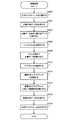
次に、本実施形態の画像処理システム1の動作について説明する。図2は、本実施形態の画像処理のフローチャートである。 Next, the operation of the
<S200> 圧縮部12は、画像処理装置10の外部(例えば、プロセッサ30)から供給される画像データの入力ビットストリームを圧縮単位(所定のコード長)で圧縮し、圧縮データを生成する。図3は、本実施形態の画像データ及び入力ビットストリームの概略図である。例えば、画像データは、6×6(=36)個のブロックを含む。圧縮単位は、所定数(例えば、4個)のブロック単位である。 <S200> The
<S202> 付加データ生成部14は、ブロックとサブブロックとの間の関係を示す圧縮付加データを生成する。画像データは、ブロックより多くのサブブロックを含む。即ち、サブブロックのサイズは、ブロックのサイズより小さい。
図4は、本実施形態の圧縮付加データの概略図である。例えば、1つのブロックは、4個のサブブロックS0〜S3からなる2×2のサイズである(図4(A))。圧縮付加データは、ブロックのサイズ(以下「ブロックサイズ」という)を示すブロックサイズ情報と、サブブロックのサイズ(以下「サブブロックサイズ」という)を示すサブブロックサイズ情報と、コード長情報と、を含む(図4(B))。コード長情報は、S200で圧縮部12において生成されたブロックごとのビットストリームにおける、各サブブロックの先頭ビット位置を示す情報である。<S202> The additional
FIG. 4 is a schematic diagram of compressed additional data according to the present embodiment. For example, one block has a size of 2 × 2 including four sub-blocks S0 to S3 (FIG. 4A). The compressed additional data includes block size information indicating a block size (hereinafter referred to as “block size”), sub-block size information indicating a sub-block size (hereinafter referred to as “sub-block size”), and code length information. Included (FIG. 4B). The code length information is information indicating the head bit position of each sub block in the bit stream for each block generated by the
<S204> メモリコントローラ19は、圧縮データと、圧縮付加データと、をメモリ20に書き込む。圧縮データと圧縮付加データは、対応付けられて記憶される。これにより、伸張部17は、メモリ20にアクセスしたときに、対応する圧縮データと圧縮付加データ(ブロックサイズ情報及びサブブロックサイズ情報)を得ることができる。 <S204> The
<S206> 画像処理部18は、メモリ20から圧縮データを読み出すためのリードリクエストを発行する。図5は、本実施形態のリードリクエストの概略図である。リードリクエストは、読み出すべき圧縮データが格納されたメモリ20の先頭アドレスを示す先頭アドレス情報と、読み出すべき圧縮データのサイズ(以下「リクエストサイズ」という)を示すリクエストサイズ情報と、を含む。 <S206> The
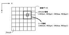
<S208> メモリコントローラ19は、リードリクエストに基づいて、メモリ20に記憶された圧縮データをブロック単位で読み出す。図6は、本実施形態のリクエスト領域及びリード領域の概略図である。 <S208> The
例えば、メモリコントローラ19は、リードリクエスト内の先頭アドレス情報及びリクエストサイズ情報に基づいて、画像データの空間において、画像処理の対象となるリクエスト領域REQの先頭座標(REQxh,REQyh)及び終端座標(REQxe,REQye)を決定する。 For example, the
次に、メモリコントローラ19は、リクエスト領域REQを含むように、画像データの空間において、読み出すべき圧縮データの領域(以下「リード領域」という)REAの先頭座標(REAxh,REAyh)及び終端座標(REAxe,REAye)を決定する。 Next, the
次に、メモリコントローラ19は、メモリ20に記憶された圧縮付加データに基づいて、リード領域REAに対応する圧縮データを特定し、特定した圧縮データと、当該圧縮データに対応する圧縮付加データと、をメモリ20から読み出す。メモリコントローラ19は、S208で読み出した圧縮データのうち、サブブロックSiに対応する圧縮データのみを、バス11を介して伸張部17へ転送するので、バス11上のデータ転送量を低減でき、バスの利用効率を改善することができる。 Next, the
<S210> サブブロック選択部16は、圧縮付加データ内のブロックサイズ情報及びサブブロックサイズ情報と、リードリクエスト内の先頭アドレス情報及びリクエストサイズ情報と、に基づいて、メモリコントローラ19が読み出した圧縮データの中から、リクエスト領域REQを含むI(Iは自然数)個のサブブロックSi(i=1〜I)を選択する。即ち、選択されるサブブロックSiには、リクエスト領域REQの少なくとも一部が含まれる。 <S210> The
図7は、本実施形態のサブブロックの概略図である。選択されるサブブロックSiの数及び選択されるサブブロックSiの位置は、ブロックサイズ、サブブロックサイズ、並びにリクエスト領域REQの先頭座標(REQxh,REQyh)及び終端座標(REQxe,REQye)により決まる(図7(A))。サブブロックSi(i=0〜3)は、1つのブロックB0から選択されても良い(図7(B))。この場合には、選択されるサブブロックSiを含むリクエストブロックRBはブロックB0と一致する。一方、サブブロックSiは、複数のブロックB0及びB1から選択されても良い(図7(C))。この場合には、リクエストブロックRBはブロックB0及びB1と一致しない。 FIG. 7 is a schematic diagram of a sub-block of this embodiment. The number of selected sub-blocks Si and the position of the selected sub-block Si are determined by the block size, the sub-block size, and the start coordinates (REQxh, REQyh) and end coordinates (REQxe, REQye) of the request area REQ (FIG. 7 (A)). The sub-block Si (i = 0 to 3) may be selected from one block B0 (FIG. 7B). In this case, the request block RB including the selected sub-block Si matches the block B0. On the other hand, the sub-block Si may be selected from a plurality of blocks B0 and B1 (FIG. 7C). In this case, the request block RB does not match the blocks B0 and B1.
<S212> 伸張部17は、S210で選択されたサブブロックSi(即ち、リクエストブロックRB)を伸張し、伸張データを生成する。伸張されるべきデータは、選択されたサブブロックSiのみであるので、従来と比べて、伸張部17の処理量を低減できる。 <S212> The
<S214> 画像処理部18は、伸張データに対して、画像処理を実行する。画像処理部18は、伸張データ(即ち、サブブロックSiに対応するデータ)のみに対して画像処理を実行するので、従来と比べて、画像処理部18の処理量を低減できる。 <S214> The
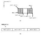
<S216> 付加データ生成部14は、伸張データに対応するサブブロック(即ち、S210で選択されたサブブロック)Siを定義するための伸張付加データを生成する。換言すると、伸張付加データは、リクエストブロックRBを定義するものである。 <S216> The additional
図8は、本実施形態の伸張付加データの概略図である。伸張付加データは、画像データの空間における、リクエストブロックRBの先頭座標(即ち、サブブロックS0の先頭座標)(RBxh,RByh)と、リクエストブロックRBのオフセット値(Ox,Oy)と、を含む(図8(A)及び(B))。オフセット値(Ox,Oy)は、リクエストブロックRBの終端座標(即ち、サブブロックS3の終端座標)(RBxe,RBye)と先頭座標(RBxh,RByh)との差である(式1)。
<S218> 画像処理部18は、プロセッサ30に、伸張付加データと、処理済画像データと、を含む出力ビットストリームを出力する。図9は、本実施形態の出力ビットストリームの概略図である。出力ビットストリームでは、ヘッダ部分に伸張付加データが配置され、ボディ部分に処理済画像データが配置される。 <S218> The
プロセッサ30は、伸張付加データを参照することによって、リクエストブロックRB内における必要な領域の位置を画定することができる。即ち、プロセッサ30には、必要な領域の位置をリクエストブロックRBの中から抽出する機能は必要ない。即ち、出力ビットストリームが伸張付加データを含むので、プロセッサ30が汎用のものであっても、処理済画像データを取り扱うことができる。 The
なお、S216は省略可能である。この場合には、S218において画像処理部18は、プロセッサ30に、処理済画像データを含む(伸張付加データを含まない)出力ビットストリームを出力する。 Note that S216 can be omitted. In this case, in S <b> 218, the
本実施形態の第1変形例について説明する。本実施形態の第1変形例では、S210において、N(Nは2以上の整数)個のリクエストブロックが選択される。また、S216において、N個のリクエストブロックに対応する伸張付加データが生成される。 A first modification of the present embodiment will be described. In the first modification of the present embodiment, N (N is an integer of 2 or more) request blocks are selected in S210. In S216, decompressed additional data corresponding to N request blocks is generated.
圧縮付加データのコード長情報は、各サブブロックSiの先頭ビット位置(但し、ラスタ順で先頭を除く)が、ラスタ順で1つ前のサブブロックに対するオフセット値として格納される。サブブロック選択部16は、コード長情報を基にして、必要なサブブロックのビットストリームをブロック単位でメモリより読み出されるビットストリームより抜き出す。 In the code length information of the compressed additional data, the head bit position (excluding the head in raster order) of each sub-block Si is stored as an offset value for the previous sub-block in raster order. Based on the code length information, the
図10は、本実施形態の第1変形例の伸張付加データの概略図である。N個のリクエストブロックに対応する伸張付加データは、画像データの空間における、1番目のリクエストブロックRB(1)の先頭座標(xh(1),yh(1))と、n(n=2〜N)番目のリクエストブロックRB(n)のオフセット値(Ox(n),Oy(n))と、を含む(図10(A)及び(B))。 FIG. 10 is a schematic diagram of decompression additional data according to the first modification of the present embodiment. The decompression-added data corresponding to N request blocks are the first coordinates (xh (1), yh (1)) of the first request block RB (1) in the image data space, and n (n = 2 to 2). (N) includes an offset value (Ox (n), Oy (n)) of the request block RB (n) (FIGS. 10A and 10B).
オフセット値(Ox(n),Oy(n))は、リクエストブロックRB(n)の終端座標(xe(n),ye(n))とリクエストブロックRB(n−1)の終端座標(xe(n−1),ye(n−1))との差に、オフセット値(Ox(n−1),Oy(n−1))を加算したものである(式2)。換言すると、オフセット値(Ox(n),Oy(n))は、N個のリクエストブロックのコード長の総和である(式3)。式3において、CL(n)(x)は、リクエストブロックRB(1)〜RB(n)のX方向のコード長であり、CL(n)(y)は、リクエストブロックRB(1)〜RB(n)のY方向のコード長である。
第1変形例によれば、伸張付加データがオフセット値(Ox(n),Oy(n)を含むので、伸張付加データがオフセット値(Ox(n),Oy(n)を含まない場合(即ち、伸張付加データが、全てのリクエストブロックRB(n)の先頭座標及び終端座標を含む場合)と比べて、伸張付加データのデータ量を低減することができる。 According to the first modification, since the extension additional data includes the offset values (Ox (n), Oy (n), the extension additional data does not include the offset values (Ox (n), Oy (n) (that is, Compared with the case where the extension additional data includes the start coordinates and the end coordinates of all the request blocks RB (n), the data amount of the extension addition data can be reduced.
本実施形態の第2変形例について説明する。本実施形態の第2変形例では、S200において、圧縮データのデータ量が所定の圧縮制限値になるように、入力ビットストリームを圧縮する。圧縮制限値は、ブロックサイズ、サブブロックサイズ、圧縮率、及びサブブロックのインデックスSiにより定義される、圧縮後のデータ量(以下「符号量」という)の下限又は上限である。また、S216において、圧縮制限値に基づいて伸張付加データが生成される。 A second modification of the present embodiment will be described. In the second modification of the present embodiment, in S200, the input bitstream is compressed so that the amount of compressed data becomes a predetermined compression limit value. The compression limit value is the lower limit or upper limit of the data amount after compression (hereinafter referred to as “code amount”) defined by the block size, the sub-block size, the compression rate, and the sub-block index Si. In S216, the decompression additional data is generated based on the compression limit value.
圧縮付加データのコード長情報は、(ラスタ順で先頭を除く)各サブブロックSiの先頭ビット位置が、サブブロックSiの圧縮時に適用される符号量上限値に対する差分として格納される。即ち、第2変形例では、サブブロックSiを圧縮する場合に、サブブロックS0〜Siで発生する符号量の総和に、上限値ULi及び下限値LLiをかけて圧縮を行い、サブブロックSiの圧縮終了時においてS0〜Siで実際に発生した符号量CiとULiとの差分値Diを、コード長情報として格納する。サブブロック選択部16は、コード長情報を基にして、必要なサブブロックのビットストリームをブロック単位でメモリより読み出されるビットストリームより抜き出す。符号量Ciは、上限値ULiと下限値LLiとの間に収まるので、差分値Diの格納に必要なビット量を削減でき、コード長情報の格納に必要となるビット量を削減できる。 The code length information of the compressed additional data is stored as a difference with respect to the code amount upper limit value applied at the time of compression of the sub-block Si at the head bit position of each sub-block Si (excluding the head in raster order). That is, in the second modification, when the sub-block Si is compressed, the sum of the code amounts generated in the sub-blocks S0 to Si is multiplied by the upper limit value ULi and the lower limit value LLi to compress the sub-block Si. The difference value Di between the code amount Ci and the ULi actually generated at S0 to Si at the end is stored as code length information. Based on the code length information, the
図11は、本実施形態の第2変形例の伸張付加データの概略図である。N個のリクエストブロックに対応する伸張付加データは、画像データの空間における、先頭座標(xh(1),yh(1))と、リクエストブロックRB(1)〜RB(n)の累積符号量AC(n)及び圧縮差分値DC(n)と、を含む(図11(A)及び(B))。累積符号量AC(n)は、リクエストブロックRB(1)〜RB(n)の符号量の総和である。(図11(C))。圧縮差分値DC(n)は、リクエストブロックRB(n)に対応する累積符号量AC(n)と、リクエストブロックRB(n)に対応する圧縮制限値SUB(n)との差である。 FIG. 11 is a schematic diagram of decompression additional data according to the second modified example of the present embodiment. The decompression-added data corresponding to the N request blocks includes the head coordinates (xh (1), yh (1)) and the accumulated code amount AC of the request blocks RB (1) to RB (n) in the image data space. (N) and the compression difference value DC (n) (FIGS. 11A and 11B). The accumulated code amount AC (n) is the sum of the code amounts of the request blocks RB (1) to RB (n). (FIG. 11C). The compression difference value DC (n) is a difference between the accumulated code amount AC (n) corresponding to the request block RB (n) and the compression limit value SUB (n) corresponding to the request block RB (n).
第2変形例によれば、伸張付加データが累積符号量AC(n)及び圧縮差分値DC(n)を含むので、第1変形例と比べて、伸張付加データのデータ量を低減することができる。 According to the second modified example, since the expanded additional data includes the accumulated code amount AC (n) and the compressed differential value DC (n), the data amount of the expanded additional data can be reduced compared to the first modified example. it can.
本実施形態によれば、ブロックではなく、サブブロックに対して画像処理が実行され、サブブロックを定義するための伸張付加データが生成される。これにより、圧縮データを伸張することによって得られるデータの品質を低下させることなく、メモリ20から圧縮データを読み出すときのバス11の利用効率を改善することができる。 According to this embodiment, image processing is performed on a sub-block instead of a block, and decompression-added data for defining the sub-block is generated. Thereby, the utilization efficiency of the bus 11 when reading the compressed data from the
本実施形態に係る画像処理システム1の少なくとも一部は、ハードウェアで構成しても良いし、ソフトウェアで構成しても良い。ソフトウェアで構成する場合には、画像処理システム1の少なくとも一部の機能を実現するプログラムをフレキシブルディスクやCD−ROM等の記録媒体に収納し、コンピュータに読み込ませて実行させても良い。記録媒体は、磁気ディスクや光ディスク等の着脱可能なものに限定されず、ハードディスク装置やメモリなどの固定型の記録媒体でも良い。 At least a part of the
また、本実施形態に係る画像処理システム1の少なくとも一部の機能を実現するプログラムを、インターネット等の通信回線(無線通信も含む)を介して頒布しても良い。さらに、同プログラムを暗号化したり、変調をかけたり、圧縮した状態で、インターネット等の有線回線や無線回線を介して、あるいは記録媒体に収納して頒布しても良い。 Further, a program that realizes at least a part of the functions of the
なお、本発明は、上述した実施形態に限定されるものではなく、その要旨を逸脱しない範囲で構成要素を変形して具体化される。また、上述した実施形態に開示されている複数の構成要素の適宜な組み合わせにより、種々の発明が形成可能である。例えば、上述した実施形態に示される全構成要素から幾つかの構成要素を削除してもよい。さらに、異なる実施形態にわたる構成要素を適宜組み合わせてもよい。 In addition, this invention is not limited to embodiment mentioned above, It deform | transforms and implements a component in the range which does not deviate from the summary. Various inventions can be formed by appropriately combining a plurality of constituent elements disclosed in the above-described embodiments. For example, you may delete a some component from all the components shown by embodiment mentioned above. Furthermore, constituent elements over different embodiments may be appropriately combined.
1 画像処理システム
10 画像処理装置
12 圧縮部
14 付加データ生成部
16 サブブロック選択部
17 伸張部
18 画像処理部
19 メモリコントローラ
20 メモリ
30 プロセッサDESCRIPTION OF
Claims (4)
Translated fromJapanese前記ブロックより小さい複数のサブブロックのそれぞれの位置情報を含む圧縮付加データを生成する圧縮付加データ生成部と、
前記圧縮付加データに基づいて、画像処理の対象となるリクエスト領域の少なくとも一部を含むサブブロックを前記圧縮データの中から選択するサブブロック選択部と、
前記選択されたサブブロックを伸張し、伸張データを生成する伸張部と、
前記伸張データに対して画像処理を実行し、処理済画像データを生成する画像処理部と、
伸張データに対応するサブブロックを定義する伸張付加データを生成する伸張付加データ生成部と、を備え、
前記伸張付加データは、前記複数のサブブロックから構成されるリクエストブロックの先頭座標と、オフセット値と、を含む画像処理装置。A compression unit that compresses an input bit stream of image data including a plurality of blocks in units of a predetermined number of blocks, and generates compressed data;
A compressed additional data generation unit that generates compressed additional data including position information of each of a plurality of sub-blocks smaller than the block;
On the basis of the compressed additional data, and the sub-block selection unit for selectinga sub-block that includes at least part of the request area to be subjected to image processing from theprevious SL compressed data,
A decompression unit that decompresses theselected sub-block and generates decompressed data;
An image processing unit that performs image processing on the decompressed data and generates processed image data;
Adecompression additional data generation unit for generating decompression additional data defining a sub-block corresponding to the decompression data,
The decompression additional data, an image processing apparatus including a first coordinate of the request block including an offset value, fromthe plurality of sub-blocks.
前記ブロックより小さい複数のサブブロックのそれぞれの位置情報を含む圧縮付加データを生成する圧縮付加データ生成部と、
前記圧縮付加データに基づいて、画像処理の対象となるリクエスト領域の少なくとも一部を含むサブブロックを前記圧縮データの中から選択するサブブロック選択部と、
前記選択されたサブブロックを伸張し、伸張データを生成する伸張部と、
前記伸張データに対して画像処理を実行し、処理済画像データを生成する画像処理部と、
伸張データに対応するサブブロックを定義する伸張付加データを生成する伸張付加データ生成部と、を備え、
前記伸張付加データは、前記複数のサブブロックから構成されるリクエストブロックのうち、1番目のリクエストブロックの先頭座標と、n(n=2〜N:Nは2以上の整数)番目のリクエストブロックのオフセット値と、を含む画像処理装置。A compression unit that compresses an input bit stream of image data including a plurality of blocks in units of a predetermined number of blocks, and generates compressed data;
A compressed additional data generation unit that generates compressed additional data including position information of each of a plurality of sub-blocks smaller than the block;
A sub-block selection unit that selects, from the compressed data, a sub-block that includes at least a part of a request area to be subjected to image processing based on the compressed additional data;
A decompression unit that decompresses the selected sub-block and generates decompressed data;
An image processing unit that performs image processing on the decompressed data and generates processed image data;
A decompression additional data generation unit for generating decompression additional data defining a sub-block corresponding to the decompression data,
The decompression additional data includes the first coordinates of the first request block and the nth (n = 2 to N: N is an integer equal to or greater than 2) th request block among the request blocks composed of the plurality of sub-blocks. And an offset value.
前記ブロックより小さい複数のサブブロックのそれぞれの位置情報を含む圧縮付加データを生成する圧縮付加データ生成部と、
前記圧縮データおよび前記圧縮付加データを記憶するメモリと、
前記圧縮データおよび前記圧縮付加データを前記メモリに書き込むメモリコントローラと、
画像処理の対象となるリクエスト領域の少なくとも一部を含むサブブロックを前記圧縮データの中から選択するサブブロック選択部と、
前記選択されたサブブロックを伸張し、伸張データを生成する伸張部と、
前記伸張データに対して画像処理を実行し、処理済画像データを生成する画像処理部と、
伸張データに対応するサブブロックを定義する伸張付加データを生成する付加データ生成部と、を備え、
前記伸張付加データは、前記複数のサブブロックから構成されるリクエストブロックの先頭座標と、オフセット値と、を含む画像処理システム。A compression unit that compresses an input bit stream of image data including a plurality of blocks in units of a predetermined number of blocks, and generates compressed data;
A compressed additional data generation unit that generates compressed additional data including position information of each of a plurality of sub-blocks smaller than the block;
A memory for storing the compressed data and the compressed additional data;
A memory controller for writing the compressed dataand the compressed additional data to the memory;
A sub-block selection unit that selects a sub-block including at least a part of a request area to be subjected to image processing from the compressed data;
A decompression unit that decompresses the selected sub-block and generates decompressed data;
An image processing unit that performs image processing on the decompressed data and generates processed image data;
An additional data generation unit that generates expanded additional data that defines a sub-block corresponding to the expanded data;
The decompression-added data is an image processing systemincluding a start coordinate of a request block composed of the plurality of sub-blocks and an offset value .
Priority Applications (2)
| Application Number | Priority Date | Filing Date | Title |
|---|---|---|---|
| JP2011209614AJP5653328B2 (en) | 2011-09-26 | 2011-09-26 | Image processing apparatus and image processing system |
| US13/329,006US9066105B2 (en) | 2011-09-26 | 2011-12-16 | Image processing device, image processing system and method for having computer perform image processing based on sub-block coding unit |
Applications Claiming Priority (1)
| Application Number | Priority Date | Filing Date | Title |
|---|---|---|---|
| JP2011209614AJP5653328B2 (en) | 2011-09-26 | 2011-09-26 | Image processing apparatus and image processing system |
Publications (2)
| Publication Number | Publication Date |
|---|---|
| JP2013074315A JP2013074315A (en) | 2013-04-22 |
| JP5653328B2true JP5653328B2 (en) | 2015-01-14 |
Family
ID=47911368
Family Applications (1)
| Application Number | Title | Priority Date | Filing Date |
|---|---|---|---|
| JP2011209614AExpired - Fee RelatedJP5653328B2 (en) | 2011-09-26 | 2011-09-26 | Image processing apparatus and image processing system |
Country Status (2)
| Country | Link |
|---|---|
| US (1) | US9066105B2 (en) |
| JP (1) | JP5653328B2 (en) |
Families Citing this family (2)
| Publication number | Priority date | Publication date | Assignee | Title |
|---|---|---|---|---|
| US9420295B2 (en)* | 2014-01-10 | 2016-08-16 | Sony Corporation | Joint mode decision with shared bit-budget condition |
| US20200143226A1 (en)* | 2018-11-05 | 2020-05-07 | Samsung Electronics Co., Ltd. | Lossy compression of neural network activation maps |
Family Cites Families (15)
| Publication number | Priority date | Publication date | Assignee | Title |
|---|---|---|---|---|
| EP0326137A3 (en)* | 1988-01-27 | 1991-10-02 | Fuji Photo Film Co., Ltd. | Image processing system |
| US5379351A (en)* | 1992-02-19 | 1995-01-03 | Integrated Information Technology, Inc. | Video compression/decompression processing and processors |
| US5253055A (en)* | 1992-07-02 | 1993-10-12 | At&T Bell Laboratories | Efficient frequency scalable video encoding with coefficient selection |
| JPH1075345A (en)* | 1996-06-26 | 1998-03-17 | Fuji Xerox Co Ltd | Image processing unit |
| JPH11178000A (en)* | 1997-12-10 | 1999-07-02 | Mitsubishi Electric Corp | Image processing device |
| GB2351407B (en)* | 1999-06-21 | 2003-06-11 | Sony Uk Ltd | Video data compression |
| US7142603B2 (en)* | 2000-01-15 | 2006-11-28 | Sony Corporation | Method and system for predictive table look-up code length of variable length code |
| JP4245576B2 (en)* | 2005-03-18 | 2009-03-25 | ティーオーエー株式会社 | Image compression / decompression method, image compression apparatus, and image expansion apparatus |
| JP4787044B2 (en)* | 2005-03-31 | 2011-10-05 | パナソニック株式会社 | Image decoding apparatus, image decoding method, image decoding program, and image decoding integrated circuit |
| JP4902474B2 (en)* | 2006-09-19 | 2012-03-21 | 株式会社リコー | Image processing apparatus and image processing method |
| US8054886B2 (en)* | 2007-02-21 | 2011-11-08 | Microsoft Corporation | Signaling and use of chroma sample positioning information |
| JP4667409B2 (en)* | 2007-02-28 | 2011-04-13 | 日本放送協会 | Image decoding apparatus and image encoding apparatus |
| JP5101962B2 (en)* | 2007-09-20 | 2012-12-19 | キヤノン株式会社 | Image coding apparatus, control method therefor, and computer program |
| US8238437B2 (en) | 2007-09-20 | 2012-08-07 | Canon Kabushiki Kaisha | Image encoding apparatus, image decoding apparatus, and control method therefor |
| JP5200803B2 (en)* | 2008-09-17 | 2013-06-05 | 株式会社リコー | Image distribution apparatus, image display apparatus, image distribution method, image display method, computer program, and information recording medium |
- 2011
- 2011-09-26JPJP2011209614Apatent/JP5653328B2/ennot_activeExpired - Fee Related
- 2011-12-16USUS13/329,006patent/US9066105B2/ennot_activeExpired - Fee Related
Also Published As
| Publication number | Publication date |
|---|---|
| US20130077881A1 (en) | 2013-03-28 |
| JP2013074315A (en) | 2013-04-22 |
| US9066105B2 (en) | 2015-06-23 |
Similar Documents
| Publication | Publication Date | Title |
|---|---|---|
| JP4697967B2 (en) | Image coding apparatus and control method thereof | |
| TWI383688B (en) | Video compression circuit and method thereof | |
| JP2017126890A (en) | Encoder and control method therefor | |
| CN103888777A (en) | Video image compression/decompression device | |
| JP2008072624A (en) | Image coding apparatus and control method thereof | |
| JP5903597B2 (en) | Image compression apparatus, image expansion apparatus, and image processing apparatus | |
| JP6186429B2 (en) | Information processing apparatus, control method, program, and recording medium | |
| JP2007251476A (en) | Image compression apparatus, image compression method, and program therefor | |
| JP5653328B2 (en) | Image processing apparatus and image processing system | |
| JP5597175B2 (en) | Image compression apparatus and image processing system | |
| KR101539260B1 (en) | Apparatus and method for lossless coding and decoding image selectively | |
| JP6377222B2 (en) | Information processing apparatus, control method, program, and recording medium | |
| JP5845202B2 (en) | Image compression apparatus and image processing system | |
| CN106919514A (en) | Semiconductor device, data processing system, and semiconductor device control method | |
| JP2009021928A (en) | Information processing apparatus and program | |
| JP2021174404A (en) | Data generation device, training device, and data generation method | |
| JP6411250B2 (en) | Image processing apparatus and image processing method | |
| JP4274187B2 (en) | Display data decompression method, display data compression / decompression method, display data decompression device, and display data compression / decompression device | |
| US10778994B2 (en) | Image processing apparatus, image processing method, and non-transitory computer-readable storage medium | |
| JP5731816B2 (en) | Image processing apparatus and image processing method | |
| JP2011229096A (en) | Image compression apparatus, image compression method, and image compression program | |
| JP2011010233A (en) | Image processing apparatus | |
| JP2011139175A (en) | Image processing apparatus and image processing method | |
| JP5640305B1 (en) | Data volume reduction device | |
| JP2005223538A (en) | Image processing circuit |
Legal Events
| Date | Code | Title | Description |
|---|---|---|---|
| A621 | Written request for application examination | Free format text:JAPANESE INTERMEDIATE CODE: A621 Effective date:20130823 | |
| A977 | Report on retrieval | Free format text:JAPANESE INTERMEDIATE CODE: A971007 Effective date:20140129 | |
| A131 | Notification of reasons for refusal | Free format text:JAPANESE INTERMEDIATE CODE: A131 Effective date:20140207 | |
| A521 | Written amendment | Free format text:JAPANESE INTERMEDIATE CODE: A523 Effective date:20140408 | |
| TRDD | Decision of grant or rejection written | ||
| A01 | Written decision to grant a patent or to grant a registration (utility model) | Free format text:JAPANESE INTERMEDIATE CODE: A01 Effective date:20141024 | |
| A61 | First payment of annual fees (during grant procedure) | Free format text:JAPANESE INTERMEDIATE CODE: A61 Effective date:20141118 | |
| LAPS | Cancellation because of no payment of annual fees |