JP5649973B2 - Optical coupling means to optical fiber and coupler manufacturing method - Google Patents
Optical coupling means to optical fiber and coupler manufacturing methodDownload PDFInfo
- Publication number
- JP5649973B2 JP5649973B2JP2010537478AJP2010537478AJP5649973B2JP 5649973 B2JP5649973 B2JP 5649973B2JP 2010537478 AJP2010537478 AJP 2010537478AJP 2010537478 AJP2010537478 AJP 2010537478AJP 5649973 B2JP5649973 B2JP 5649973B2
- Authority
- JP
- Japan
- Prior art keywords
- fiber
- pump
- diameter
- signal
- capillary tube
- Prior art date
- Legal status (The legal status is an assumption and is not a legal conclusion. Google has not performed a legal analysis and makes no representation as to the accuracy of the status listed.)
- Active
Links
- 230000008878couplingEffects0.000titleclaimsdescription35
- 238000010168coupling processMethods0.000titleclaimsdescription35
- 238000005859coupling reactionMethods0.000titleclaimsdescription35
- 230000003287optical effectEffects0.000titleclaimsdescription26
- 238000004519manufacturing processMethods0.000titleclaimsdescription8
- 239000013307optical fiberSubstances0.000titledescription12
- 239000000835fiberSubstances0.000claimsdescription220
- 230000035515penetrationEffects0.000claimsdescription30
- 238000000034methodMethods0.000claimsdescription26
- 239000011521glassSubstances0.000claimsdescription14
- 230000005855radiationEffects0.000claimsdescription10
- 239000007787solidSubstances0.000claimsdescription3
- 238000005530etchingMethods0.000claimsdescription2
- 239000011162core materialSubstances0.000description24
- 238000005520cutting processMethods0.000description14
- 238000013459approachMethods0.000description6
- 239000011248coating agentSubstances0.000description5
- 238000000576coating methodMethods0.000description5
- VYPSYNLAJGMNEJ-UHFFFAOYSA-NSilicium dioxideChemical compoundO=[Si]=OVYPSYNLAJGMNEJ-UHFFFAOYSA-N0.000description4
- 239000005350fused silica glassSubstances0.000description4
- 229920000642polymerPolymers0.000description4
- 230000008569processEffects0.000description4
- 238000005253claddingMethods0.000description3
- 238000002844meltingMethods0.000description3
- 230000008018meltingEffects0.000description3
- 230000005540biological transmissionEffects0.000description2
- 230000015556catabolic processEffects0.000description2
- 238000004891communicationMethods0.000description2
- 238000006731degradation reactionMethods0.000description2
- 238000010438heat treatmentMethods0.000description2
- 238000005498polishingMethods0.000description2
- 238000012545processingMethods0.000description2
- 230000009467reductionEffects0.000description2
- 241000270281Coluber constrictorSpecies0.000description1
- 229910052691ErbiumInorganic materials0.000description1
- 229910052769YtterbiumInorganic materials0.000description1
- 238000010521absorption reactionMethods0.000description1
- 238000005452bendingMethods0.000description1
- 239000012141concentrateSubstances0.000description1
- 238000010276constructionMethods0.000description1
- 238000013461designMethods0.000description1
- 238000010891electric arcMethods0.000description1
- UYAHIZSMUZPPFV-UHFFFAOYSA-NerbiumChemical compound[Er]UYAHIZSMUZPPFV-UHFFFAOYSA-N0.000description1
- 230000005284excitationEffects0.000description1
- OQZCSNDVOWYALR-UHFFFAOYSA-NflurochloridoneChemical compoundFC(F)(F)C1=CC=CC(N2C(C(Cl)C(CCl)C2)=O)=C1OQZCSNDVOWYALR-UHFFFAOYSA-N0.000description1
- 238000005304joiningMethods0.000description1
- 238000003754machiningMethods0.000description1
- 239000000463materialSubstances0.000description1
- 238000010309melting processMethods0.000description1
- 229910052751metalInorganic materials0.000description1
- 239000002184metalSubstances0.000description1
- 238000004021metal weldingMethods0.000description1
- 238000005459micromachiningMethods0.000description1
- 238000012986modificationMethods0.000description1
- 230000004048modificationEffects0.000description1
- 239000000615nonconductorSubstances0.000description1
- 238000001579optical reflectometryMethods0.000description1
- 238000005086pumpingMethods0.000description1
- 150000002910rare earth metalsChemical group0.000description1
- 238000002310reflectometryMethods0.000description1
- 238000006748scratchingMethods0.000description1
- 230000002393scratching effectEffects0.000description1
- 230000008054signal transmissionEffects0.000description1
- NAWDYIZEMPQZHO-UHFFFAOYSA-NytterbiumChemical compound[Yb]NAWDYIZEMPQZHO-UHFFFAOYSA-N0.000description1
Images


Classifications
- G—PHYSICS
- G02—OPTICS
- G02B—OPTICAL ELEMENTS, SYSTEMS OR APPARATUS
- G02B6/00—Light guides; Structural details of arrangements comprising light guides and other optical elements, e.g. couplings
- G02B6/24—Coupling light guides
- G02B6/26—Optical coupling means
- G02B6/28—Optical coupling means having data bus means, i.e. plural waveguides interconnected and providing an inherently bidirectional system by mixing and splitting signals
- G02B6/2804—Optical coupling means having data bus means, i.e. plural waveguides interconnected and providing an inherently bidirectional system by mixing and splitting signals forming multipart couplers without wavelength selective elements, e.g. "T" couplers, star couplers
- G02B6/2821—Optical coupling means having data bus means, i.e. plural waveguides interconnected and providing an inherently bidirectional system by mixing and splitting signals forming multipart couplers without wavelength selective elements, e.g. "T" couplers, star couplers using lateral coupling between contiguous fibres to split or combine optical signals
- G02B6/2835—Optical coupling means having data bus means, i.e. plural waveguides interconnected and providing an inherently bidirectional system by mixing and splitting signals forming multipart couplers without wavelength selective elements, e.g. "T" couplers, star couplers using lateral coupling between contiguous fibres to split or combine optical signals formed or shaped by thermal treatment, e.g. couplers
- G—PHYSICS
- G02—OPTICS
- G02B—OPTICAL ELEMENTS, SYSTEMS OR APPARATUS
- G02B6/00—Light guides; Structural details of arrangements comprising light guides and other optical elements, e.g. couplings
- G02B6/24—Coupling light guides
- G02B6/25—Preparing the ends of light guides for coupling, e.g. cutting
- G—PHYSICS
- G02—OPTICS
- G02B—OPTICAL ELEMENTS, SYSTEMS OR APPARATUS
- G02B6/00—Light guides; Structural details of arrangements comprising light guides and other optical elements, e.g. couplings
- G02B6/24—Coupling light guides
- G02B6/26—Optical coupling means
- G02B6/28—Optical coupling means having data bus means, i.e. plural waveguides interconnected and providing an inherently bidirectional system by mixing and splitting signals
- G02B6/2804—Optical coupling means having data bus means, i.e. plural waveguides interconnected and providing an inherently bidirectional system by mixing and splitting signals forming multipart couplers without wavelength selective elements, e.g. "T" couplers, star couplers
- G02B6/2856—Optical coupling means having data bus means, i.e. plural waveguides interconnected and providing an inherently bidirectional system by mixing and splitting signals forming multipart couplers without wavelength selective elements, e.g. "T" couplers, star couplers formed or shaped by thermal heating means, e.g. splitting, branching and/or combining elements
- H—ELECTRICITY
- H01—ELECTRIC ELEMENTS
- H01S—DEVICES USING THE PROCESS OF LIGHT AMPLIFICATION BY STIMULATED EMISSION OF RADIATION [LASER] TO AMPLIFY OR GENERATE LIGHT; DEVICES USING STIMULATED EMISSION OF ELECTROMAGNETIC RADIATION IN WAVE RANGES OTHER THAN OPTICAL
- H01S3/00—Lasers, i.e. devices using stimulated emission of electromagnetic radiation in the infrared, visible or ultraviolet wave range
- H01S3/09—Processes or apparatus for excitation, e.g. pumping
- H01S3/091—Processes or apparatus for excitation, e.g. pumping using optical pumping
- H01S3/094—Processes or apparatus for excitation, e.g. pumping using optical pumping by coherent light
- H01S3/094003—Processes or apparatus for excitation, e.g. pumping using optical pumping by coherent light the pumped medium being a fibre
- H01S3/094011—Processes or apparatus for excitation, e.g. pumping using optical pumping by coherent light the pumped medium being a fibre with bidirectional pumping, i.e. with injection of the pump light from both two ends of the fibre
Landscapes
- Physics & Mathematics (AREA)
- General Physics & Mathematics (AREA)
- Optics & Photonics (AREA)
- Lasers (AREA)
- Optical Couplings Of Light Guides (AREA)
Description
Translated fromJapanese【技術分野】
【0001】
本発明は、請求項1の前段部分に記載の光カプラに関するものである。
【0002】
また本発明は、光カプラの製造方法にも関するものである。
【背景技術】
【0003】
ファイバレーザーは、さまざまな産業上の利用に適応する多数の魅力的な性質を持っている。これらの性質は、良好なビーム品質、容易な温度管理、小型、良好な効率性を備えている。そのためファイバレーザーは、固体レーザーおよびガスレーザーなどの、より従来型のレーザーから市場シェアを継続的に獲得してきている。ファイバレーザーは、優れたビーム品質の光出力を数kW台で生成することができる。したがって、これらのレーザーは、金属の溶接あるいは切断のようなマクロ的機械加工の適用に使用することができる。さらにファイバレーザーは、モード同期方法により超短パルスの動作に役立ち、同様にマイクロ的機械加工の適用に使用することができるようにしている。
【0004】
以下の説明において、本明細書の読者は光ファイバ構造の基礎知識があると仮定される。したがって、ファイバコア、クラッドおよび被覆の概念は、詳述しない。ファイバレーザーによって生成されたレーザー放射は、ここでは信号と呼ばれる、直径が一般的に数ミクロンと数十ミクロンの間であるファイバのコア内に伝播すると述べるにとどめておく。いわゆるダブルクラッドファイバは、コアと、前記コアに信号光を閉じ込めてポンプ光(励起光)を導く第一クラッドと、前記第一クラッドに前記ポンプ光を閉じ込める第二クラッドとから成る。前記コアは、一般的にドープ溶融石英で作製され、前記第一クラッドは溶融石英で作製され、前記第二クラッドは低屈折率ポリマーあるいはドープ溶融石英で作製される。ポンプ光の意味については後に説明する。
【0005】
後の参照のために、ファイバ加工に関連したいくつかのさらなる用語あるいは概念もまた、ここで簡潔に説明される。接合は、ファイバ光学の技術分野において周知の用語である。それは、接合部に近接した2つのガラス部分を高温に加熱してガラスを軟質にして、次に2つのガラス部分を互いに物理的接触するように押し付けて、少なくとも2つのガラス部分を接合することである。故に、密接で透明な接触部は、2つのガラス部分の間で形成される。接合の熱源は、例えば電気アーク、熱フィラメントあるいはCO2レーザーであることができる。切断加工は、ガラス接触部分に対して平らな面を形成するように、ガラス部分を切断することを意味する。光ファイバにおいて、切断面は通常、ファイバの光軸とは本質的に垂直に存在する(垂直切断)。また本質的に垂直でないものも存在する(角度切断)。特に明記しない限り、本明細書では切断加工は、垂直切断を作成することを意味する。ファイバの先端に平らな面を得る等価手段は、より困難ではあるが、周知の機械研磨方法である。切断加工は、硬質材料で作製された鋭利な刃でファイバに傷を付け、ファイバに張力を加えて切断することによって、あるいはレーザーによって切断する、機械的手段で実行できる。光ファイバの良好な切断は、高品質な接合を可能にする。ストリッピング(被覆剥き)は、通常ファイバの末端から数センチの距離で、ファイバからポリマー被覆を除去することを意味する。本明細書では縮径は、軟質にして、表面張力及び/又は断片の内外領域間の圧力差によって収縮するために、キャピラリ管などの、ガラスからなる中空状の断片を加熱することである。加熱は、接合と同じ方法で実行できる。
【0006】
如何なるレーザーでもファイバレーザーは、利得媒体、光共振器、前記利得媒体へのエネルギー結合手段、および前記光共振器から光を取り出す手段から成る。ファイバレーザーの利得媒体は、光ファイバと、一般的に溶融石英で作製されたアクティブファイバから成り、そのアクティブファイバのコアは、希土類原子Er(エルビウム)あるいはYb(イッテルビウム)などの、光学活性原子を添加している。光共振器は、アクティブファイバに対して正確に位置あわせされたときに、活性原子によって放出された光の一部に、利得媒体を通りミラー間で跳ね返させて、増幅された光を得るミラーで、利得媒体を囲むことで形成される。ミラーは、大きな光ミラーであるか、それとも光ファイバ内に直接加工できる。後者の場合では、ミラーはファイバブラッググレーティング(FBR)であるが、ファイバをベースとしたミラーもまた存在する。ファイバをベースとしたミラーは、極めて低光損失の他のファイバに直接接続されるか、または接合されることができるので、魅力的である。ミラー、または一般に2つのミラーのうちの1つだけが、光共振器から光を取り出す手段を提供するために、一部分だけの反射を持たせる。ファイバレーザーでは、取り出された光は、加工物などの、興味のある点に近接して光ファイバを使ってさらに導波されることができる。したがって取り出された光は、最終用途で用いることができるレーサー光線を形成する。
【0007】
利得媒体、すなわちファイバレーザーにおけるアクティブファイバは、電気絶縁体である。したがって、エネルギーを電力形式でアクティブファイバに直接供給することができない。しかし活性原子は、吸収帯と呼ばれるある波長範囲内で光放射を吸収する。この特性は、光形式で利得媒体にエネルギーを入れる、あるいは「ポンピングする」ことで、ファイバレーザーに利用される。この光はポンプ光と呼ばれ、ポンプレーザーダイオードによって通常作り出され、好ましくはファイバ結合される。したがってファイバレーザーにおいて、前記ポンプ光をアクティブファイバに結合する手段が存在しなければならない。さらに好ましくは、その結合手段が低光学損失を有すること、すなわちポンプエネルギーのほとんどが、利得媒体に結合できることである。さらに好ましくは、その結合手段は、レーザー信号が低光学損失で通過できる信号貫通を有することである。後者の特性は、レーザーキャビティ構造に大いに役立ち、産業分野のファイバレーザーの好適な前提条件である。
【0008】
米国特許第5854865号明細書、米国特許第6529657号明細書、特開2007−156097号公報に示された光通信など、自由空間光通信を用いてポンプカプラを作製する多くの方法がある。これらの取り組み方法は、溶融型全ガラスカプラである本発明とは根本的に異なる。したがって以下の説明は、溶融型全ガラスの実施を有する先行技術に集中している。
【0009】
米国特許第5864644号明細書(特許文献1)では、信号ファイバを含むことのできる入力ファイバは、共に単に束ねられ、共にファイバを溶融するためにテーパーにされる。次に溶融された束は、ウエスト部から切断され、出力ファイバに接合される。この取り組み方法もまた、ポンプファイバも信号ファイバもテーパーにするのを含む。信号ファイバのコア径は、その過程で減少される。さらに出力ファイバは、低接合損失に対し、同一の減少コア径を有することが必要である。したがってこのカプラは、入力および出力で異なるコア径を避けられなく有する。
【0010】
米国特許第5999673号明細書(特許文献2)では、カプラはポンプファイバをテーパーにして、ポンプ光を従って信号ファイバに結合することができるようにするテーパー部から信号伝送中央ファイバにそのポンプファイバを溶融することで、作製される。ポンプファイバは、ゼロの厚さでテーパーにすることができないので、ポンプ光のある損失がこの取り組み方法で予期される。さらに、その延伸長さに沿って信号ファイバに多数のポンプファイバを直接溶融することは、信号ファイバを屈曲して、信号光にマイクロベンド損失を引き起こす危険性がある。各ポンプファイバは、多数のポンプファイバを含む構造に対して面倒な工程の極小の厚さでテーパーにする必要もある。
【0011】
米国特許出願公開第2005/105866号明細書(特許文献3)は、ポンプファイバは、ファイバの縦軸に沿ってアクティブファイバと本質的に光接触した状態にあるカプラを記載している。この実施では、ポンプファイバが、例えばポリマー被覆で構造全体を被覆するか、あるいは縦軸に沿ってファイバを溶融することで、ファイバ間で光接触して保持するために、アクティブファイバと同じファイバ線引き工程で製造する必要がある。さらにこの取り組み方法は、信号ファイバのコアが信号ファイバ長に沿ってポンプ放射を吸収しているときのみ、パワーの効率的結合が達成できるので、アクティブファイバであるためには信号ファイバを必要とする。この取り組み方法は、信号のビーム品質を十分に保持するが、ポンプパワーでは限られた拡張性を有し、アクティブファイバであるためには信号ファイバを実際に必要とし、ポンプファイバと信号ファイバとの間で光接触を達成するためには、複雑な方法を必要とする。
【0012】
米国特許出願公開第2005/105854号明細書(特許文献4)では、一束のポンプファイバは、中央のファイバの周囲に形成され、最初に共に溶融される。次にその束は、出力ファイバに直接接合される。信号ファイバのコアと出力ファイバのコアとの慎重な位置合わせ、および出力ファイバにすべてのポンプファイバとの良好な接触をすることもまた必要とするので、このような接合を実行することは、極めて挑戦的である。
【0013】
米国特許出願公開第2006/251367号明細書(特許文献5)は、非ガイドコアを備える少なくとも第一の入力光ファイバと、少なくとも1つの出力光ファイバを有する光ファイバカプラを記載している。この発明は、カプラの本質的特性である実結合領域の構造を実際には詳細に記載していないことにおいては、極めて漠然としている。請求項9にのみ、結合領域がファイバのテーパー束であることを述べており、したがって本発明の結合領域とは根本的に異なる。したがって、この特許は疑わしい実用性にある。結合領域の詳細な説明は何も与えられていないので、このようなカプラを実際に構成するための基準として使用することはできない。さらにそれは、非ガイド入力ファイバに限定される。
【0014】
国際公開第2007/090272号(特許文献6)は、多数のテーパーポンプファイバがマルチクラッドシングルファイバに側面に沿って結合される構造を有するマルチモードファイバカプラを記載している。溶融工程では、テーパーポンプファイバと中央ファイバとの束にひねりを加え加熱し延伸して、その束においてさらにウエスト部を備えたテーパーを形成する。次に溶融された束は、ウエスト部から切断され、別のマルチクラッドファイバに接合される。カプラを作製するこの取り組み方法の欠点は、各ポンプファイバが別々にテーパーにする必要があるという点である。
【0015】
さらにひねりと溶融された束の形成過程で、中心信号伝送ファイバもまた、特にそのコアの大きさに変形されてテーパーにされる。このことは、信号パワーに対する避けることのできない被った損失のために、信号光に対する低下したモード品質のために、およびコア材料に対するレーザー損傷閾値に到達する危険性のために、ハイパワーファイバレーザーで用いられるカプラには好ましくない。
【先行技術文献】
【特許文献】
【0016】
【特許文献1】米国特許第5864644号明細書
【特許文献2】米国特許第5999673号明細書
【特許文献3】米国特許出願公開第2005/105866号明細書
【特許文献4】米国特許出願公開第2005/105854号明細書
【特許文献5】米国特許出願公開第2006/251367号明細書
【特許文献6】国際公開第2007/090272号
【発明の概要】
【発明が解決しようとする課題】
【0017】
本発明は、ポンプ光を光ファイバに結合する実用的手段と、その製造方法を記載している。このことから、用語「ポンプカプラ」は、その結合手段に用いられる。本発明のカプラは、如何なるポンプファイバにもテーパー部を有するものでもないし、信号ファイバのコアにテーパー部を有するものでもないが、その結合は、テーパーのキャピラリ管を用いて実行され、ポンプファイバと信号ファイバは、そのキャピラリ管に結合される。
【課題を解決するための手段】
【0018】
すなわち、本発明の装置は、請求項1の特徴部分に記載されていることを特徴とする。
【0019】
すなわち、本発明の方法は、請求項9の特徴部分に記載されていることを特徴とする。
【0020】
以下の恩恵は、本発明によって得られるものである。
【0021】
本発明では、ポンプカプラは、ファイバレーザーによって生成されるレーザー放射に対して低損失な信号貫通を有する特性を持っている。さらに、本発明の手順で作製された信号貫通は、その信号貫通ファイバを通って移動するレーザー放射に対するビーム品質の最小限の低下を引き起こすだけである。最後に本発明のカプラ構造を備えることで、出力ファイバに極めて高いポンプ結合効率を得ることは可能である。
【図面の簡単な説明】
【0022】
【図1】本発明に関連して用いることができるファイバレーザーの一例を概略的に示す。
【図2】本発明に関連して用いることができるファイバレーザーの第二例を概略的に示す。
【図3】本発明に関連して用いることができるファイバレーザーの第三例を概略的に示す。
【図4】本発明に関連して用いることができるファイバレーザーの第四例を概略的に示す。
【図5a】本発明に記載の1つのポンプカプラの部分横断面の側面図を示す。
【図5b】図5aの横断面Aを示す。
【図6】本発明に記載の方法で用いることができる6本のポンプファイバと1本の信号貫通ファイバを備えた典型的な光ファイバ束の横断面を示す。
【図7】図6の光ファイバ束の側面図を示す。
【図8】本発明に記載の方法の図6、図7の次の段階の構造の側面図を示す。
【図9】本発明に記載の方法の図6、図7、図8の次の段階の構造の側面図を示す。
【図10】本発明に記載の方法の方法ステップに関連したポンプカプラの予備構造の側面図を示す。
【図11】本発明に記載の方法の図10の次の段階の構造の側面図を示す。
【図12】本発明に記載の方法の図10、図11の次の段階の構造の側面図を示す。
【発明を実施するための形態】
【0023】
図1は、ファイバレーザーの構成の一例を示している。それは、ファイバをベースとしたレーザー共振器1で構成され、アクティブファイバ11と、高反射ファイバブラッググレーティング(HR FBG)ミラー12と、低反射ファイバブラッググレーティング(LR FBG)ミラー13とから成る。低反射ファイバブラッググレーティング(LR FBG)は、100%より大幅に小さな光反射率を有することで、レーザー共振器1からレーザー放射を取り出す手段をさらに提供する。高反射(HR)および低反射(LR)ファイバブラッググレーティング(FBR)の標準反射率は、それぞれ>90%および10%である。図1は、ポンプカプラ2もまた表している。そのポンプカプラ2はそれぞれ、ポンプファイバ31を通ってポンプ光源に接合し、信号貫通ファイバ32を通って外界に接合し、出力信号ファイバ50を通ってファイバレーザー共振器に接合している。図1のファイバレーザーキャビティは、ポンプ光と出力信号光が逆向き伝播している、いわゆる逆向きポンプ構造を有する。さらに図1の例でポンプカプラ2は、レーザー共振器1の外側に位置する。図1のバツ印は、異なるファイバ間の接合部を表す。
【0024】
図2は、図1と同じ意味を有する表記の、ファイバレーザーの別例を示している。図1の共振器に対する唯一の違いは、ポンプカプラ2が現在レーザー共振器1の内側、すなわち高反射(HR)ミラー12と低反射(LR)ミラー13との間にある、という点である。図2の構造において、ポンプカプラがレーザー共振器1の光学的損失に直接寄与しているので、ポンプカプラが低損失の信号貫通を有することは必要である。
【0025】
図3は、ファイバレーザーのさらに別の構造を示している。本例においてファイバレーザー共振器は、レーザー共振器1の両端から2つのポンプカプラ2a、2bでポンプされる。示された構造の拡張あるいは変更によって、他の構造が構築されることができることは明らかである。
【0026】
各ポンプカプラのパワー結合能力が限定されるように、ハイパワーファイバレーザーは、アクティブファイバの複数の区分とポンプカプラを連結することによって構築されることができる。図4は、2つのアクティブファイバ区分11a、11bに接続された4つのポンプカプラ2a、2b、2c、2dを有するファイバレーザーの一例を示す。区分11aは、ポンプカプラ2a、2bで両端からポンプされ、さらにアクティブファイバ区分11bは、ポンプカプラ2c、2dで両端からポンプされる。高反射(HR)ミラー12と低反射(LR)ミラー13は、それぞれポンプカプラ2a、2dの信号貫通ファイバに取り付けられている。
【0027】
上述例は、柔軟性のあるパワー拡張可能なファイバレーザーが、低損失のポンプカプラで製造できる、ということを示している。本発明は、低損失のポンプカプラの概念と、このようなポンプカプラを製造する方法を説明している。
【0028】
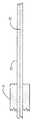
図5aは、ポンプカプラ2の一実施例を示している。カプラ2は、光軸が本質的に平行であり、切断端部あるいは研磨端部が、カプラ2の光軸22に垂直な同一平面上にあるように本質的に配置された多数のポンプファイバ31から成る。ここで注目することは、2つのポンプファイバ31だけがこの切断面で描かれているが、当然のことながら、ポンプファイバの数がそれより多い、例えば4あるいは6つである。1つの限定減縮は、ポンプファイバ束の中央にポンプファイバが位置しないことである。ポンプファイバ31は、次に先頭外径D1で内径D2を有するテーパー状のキャピラリ管40の切断端部あるいは研磨端部に接合される。本実施例においてキャピラリ管40のテーパー部は、周知のガラスの線引き方法で形成される。従って、キャピラリ管40のテーパー部の外径および内径いずれも、テーパーに沿って変化するが、それらの割合は、本質的に一定のままである。カプラ2のポンプ光の低光学損失に関し、ポンプ光の入口端部でのキャピラリ管の壁厚Wcは、ポンプファイバの直径D5に好ましくは等しいか、あるいはより大きい。これは、ポンプファイバからのポンプ光がすべてキャピラリ管40のガラス部分と結合できることを確実にする。キャピラリ管40のテーパー部は、好ましくは断熱であり、管の横寸法が、テーパー状キャピラリに沿って進む光の輝度が本質的に一定であるようにキャピラリの長さに沿ってゆっくりと変化するという意味がある。本明細書の輝度は、テーパー部の内部の任意の長手方向の位置における、キャピラリの壁厚と光の開口数(NA)の積を意味する。キャピラリ管40は、外径D1および内径D2の幅広の第一端部65と、外径D3および内径D4の幅狭の第二端部70を有する。ポンプファイバ束の中央およびキャピラリ管40のテーパー部の中心孔の内部に、信号貫通ファイバ32が配置される。信号貫通ファイバ32の直径D6は、テーパー状のキャピラリ管40の内孔径D4よりもわずかに小さい。この限定減縮は、信号貫通ファイバ32の全長に適用する必要がないが、キャピラリ管40のテーパー部のウエスト領域に固定される部分のみに適用しなければならないということを明らかにすべきである。キャピラリ管40が長さLcの領域45内で信号貫通ファイバ32にまで縮径されて、したがってキャピラリ管40と信号貫通ファイバ32を融合するように作製して、前記領域45で固体ガラスを形成する。縮径領域45は、テーパー部の端部まで高品質切断の作製を容易にする。テーパー部の切断は、ファイバ切断で用いられたいずれかの方法で行われる。テーパー部の前記切断端部70は、出力信号ファイバ50、好ましくはダブルクラッドファイバに接合され、その結果信号ファイバ32のコア33は、出力信号ファイバ50のコア53と本質的に位置合わせされる。ファイバ32、50のコア径と開口数は、本質的に同一に好ましくは選択される。これは、レーザー放射あるいは信号が、パワーおよびビーム質の損失を最小限に抑えてカプラ2を貫通できることを確実にする。カプラ2を通じた良好なポンプ光の伝送に関し、キャピラリ管40のテーパー部のウエスト径D3は、出力信号ファイバ50の直径D7と本質的に等しいか、あるいはより小さく選択される。
【0029】
図5bは、信号ファイバ32の周囲に、全部で8本のポンプファイバ31を示す図5aの方向Aに沿った横断面を示す。ポンプファイバ31の数は、一般的に6本から8本である。
【0030】
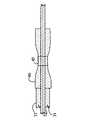
図9は、本発明のポンプカプラ2の他の実施例を示している。本実施例において、キャピラリ管40のテーパー部は、キャピラリ管40の外面を化学的にエッチングすることによって形成される。したがってその外径のみが、キャピラリ管40のテーパー部に沿って変化し、内孔径D4=D2である。本実施例における他の特徴は、図5aのものと本質的に類似している。
【0031】
ファイバの開口数(NA)は、第一近似において、放射の円錐形がファイバから空気中に出射する際、ファイバ軸で作成する最大角に等しい。当業者が上記説明から容易に理解できるように、ポンプファイバ31からキャピラリ管40のテーパー部に入射しているポンプ光の開口数NA1は、第一近似において、キャピラリ管40のテーパー部により、NA2=NA1*D1/D3の式に従って開口数の値NA2まで増加するだろう。したがってカプラ2は、NA2が出力信号ファイバ50のポンプ導波路の最大開口数NA3を超えないように設計されるべきである。ダブルクラッド出力信号ファイバに関し、NA3の値は一般的に約0.46であり、低屈折率のポリマー被覆によって達成される。したがって、設計基準NA2≦NA3を守ることで、ポンプファイバ31から出力信号ファイバ50への良好な伝送を備えたカプラが実現できる。これはカプラ2の第一の課題である。第二の課題は、最小損失とビーム品質の最小劣化を備えたカプラを通じて信号貫通ファイバ32と出力信号ファイバ50のコア内部で進むレーザー放射を伝送することである。これはコア径と開口数が本質的に同一であるようにファイバ32、50を選択することで、好ましくは達成される。
【0032】
図6の記載において、本発明に記載の第一の方法は、信号ファイバ32にポンプファイバ31を束ねることから始まる。図7から示されるように、ポンプファイバ31の切断端部は、同一平面で面一になるように位置合わせされる。
【0033】
キャピラリ管のウエスト部は、キャピラリ管40の外径だけが縮小し、キャピラリ管40の内径が同じままであるように、エッチングすることで形成される。
【0034】
図7のこの構造は、図8に記載の、例えば接合によって、キャピラリ管40とさらに接続される。キャピラリ管40の領域45は、次にウエスト部から信号ファイバ32まで縮径される。
【0035】
図9の記載において、キャピラリ管40は縮径部45から切断され、別のダブルクラッド出力信号ファイバ50は、信号ファイバのコアと位置あわせされるように、切断されたキャピラリ管40に接合される。
【0036】
本発明に記載の第二の方法は、図10−12に関連して説明される。この解法では、キャピラリ管40の内径も外径も共に、テーパー部で減少している。
【0037】
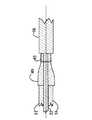
図10の記載において、ポンプファイバ31のファイバ束は、束にする補助ファイバ60の周囲に形成され、その補助ファイバ60の直径は、キャピラリ管40の内径とほぼ同一である。束にする補助ファイバ60は、ポンプファイバ31の範囲までは拡張しない。ポンプファイバ31はキャピラリ管40に接合され、補助ファイバ60は取り除かれ、少なくともキャピラリ管40のウエスト部を通って押し出される部分において、補助ファイバ60よりも小さい直径を一般的に備えた信号貫通ファイバ32に置き換えられる。補助ファイバ60は、ファイバ以外の構造、例えば金属線であってもよい。したがって、用語「補助具」もまたこれに関連して用いることができる。信号貫通ファイバ32をキャピラリ管40に適合させる第一の実施において、信号貫通ファイバ32の外面は、キャピラリ管40の直径D4の内孔を丁度通り抜けることができるように、化学的にエッチングされる。信号貫通ファイバ32をキャピラリ管40に適合させる別の実施において、ファイバ32はD4よりもわずかに小さいその元の直径を有するように設計される。
【0038】
図11に示すように、キャピラリ管40はテーパーウエスト部45から信号貫通ファイバ32まで縮径される。
【0039】
図12の記載において、キャピラリ管は、縮径ウエスト部45の部分から切断され、ダブルクラッド出力信号ファイバ50は、切断されたキャピラリ管40に接合される。
【符号の説明】
【0040】
2 ポンプカプラ
22 光軸
31 ポンプファイバ
32 信号貫通ファイバ
33 コア
40 キャピラリ管(テーパー部)
45 縮径領域
50 出力信号ファイバ
53 コア
65 第一端部(幅広)
70 第二端部(幅狭)
D1 幅広側の外径
D2 幅広側の内径
D3 幅狭側の外径
D4 幅狭側の内径
D5 ポンプファイバの直径
D6 信号貫通ファイバの直径
D7 出力信号ファイバの直径
Lc 縮径領域
Wc 壁厚【Technical field】
[0001]
The present invention relates to an optical coupler according to the first part of claim 1.
[0002]
The present invention also relates to a method for manufacturing an optical coupler.
[Background]
[0003]
Fiber lasers have a number of attractive properties that adapt to various industrial applications. These properties provide good beam quality, easy temperature management, small size, and good efficiency. As a result, fiber lasers continue to gain market share from more conventional lasers such as solid state lasers and gas lasers. Fiber lasers can produce light output with excellent beam quality on the order of several kW. Thus, these lasers can be used in macro-machining applications such as metal welding or cutting. Furthermore, fiber lasers are useful for operating ultrashort pulses by means of a mode-locking method and can be used for micromachining applications as well.
[0004]
In the following description, it is assumed that the reader of this specification has a basic knowledge of fiber optic structures. Therefore, the concept of fiber core, cladding and coating will not be described in detail. It is mentioned that the laser radiation produced by the fiber laser propagates in a fiber core, here called a signal, which is typically between a few microns and a few tens of microns in diameter. A so-called double clad fiber includes a core, a first clad for confining signal light in the core and guiding pump light (excitation light), and a second clad for confining the pump light in the first clad. The core is generally made of doped fused silica, the first cladding is made of fused silica, and the second cladding is made of a low refractive index polymer or doped fused silica. The meaning of the pump light will be described later.
[0005]
For later reference, some additional terms or concepts related to fiber processing are also briefly described here. Bonding is a well-known term in the field of fiber optics. It heats two glass parts close to the joint to a high temperature to soften the glass, and then presses the two glass parts into physical contact with each other to join at least two glass parts. is there. Thus, a close and transparent contact is formed between the two glass parts. The heat source for joining is, for example, an electric arc, a hot filament, or CO2 Can be a laser. Cutting processing means cutting the glass portion so as to form a flat surface with respect to the glass contact portion. In an optical fiber, the cutting plane is usually essentially perpendicular to the optical axis of the fiber (vertical cutting). Some are not essentially vertical (angular cutting). Unless specified otherwise, cutting herein means making a vertical cut. An equivalent means of obtaining a flat surface at the tip of the fiber, although more difficult, is a well-known mechanical polishing method. The cutting process can be performed by mechanical means by scratching the fiber with a sharp blade made of a hard material, applying tension to the fiber and cutting it, or cutting with a laser. Good cutting of the optical fiber enables high quality bonding. Stripping means removing the polymer coating from the fiber, usually a few centimeters from the end of the fiber. As used herein, reducing diameter is heating a hollow piece of glass, such as a capillary tube, to soften and shrink due to surface tension and / or pressure differences between the inner and outer regions of the piece. Heating can be performed in the same way as bonding.
[0006]
Any laser fiber laser comprises a gain medium, an optical resonator, energy coupling means to the gain medium, and means for extracting light from the optical resonator. The gain medium of a fiber laser consists of an optical fiber and an active fiber generally made of fused silica, and the core of the active fiber contains optically active atoms such as rare earth atoms Er (erbium) or Yb (ytterbium). It is added. An optical resonator is a mirror that, when accurately aligned with an active fiber, causes some of the light emitted by the active atoms to bounce between the mirrors through the gain medium to obtain amplified light. It is formed by surrounding the gain medium. The mirror can be a large optical mirror or can be processed directly into the optical fiber. In the latter case, the mirror is a fiber Bragg grating (FBR), but there are also fiber based mirrors. Fiber-based mirrors are attractive because they can be directly connected or joined to other fibers with very low optical loss. Only one of the mirrors, or generally two of the mirrors, has a partial reflection to provide a means of extracting light from the optical resonator. In a fiber laser, the extracted light can be further guided using an optical fiber in the vicinity of a point of interest, such as a workpiece. The extracted light thus forms a racer beam that can be used in the final application.
[0007]
The gain medium, ie the active fiber in the fiber laser, is an electrical insulator. Therefore, energy cannot be supplied directly to the active fiber in the form of power. However, active atoms absorb light radiation within a certain wavelength range called the absorption band. This property is exploited in fiber lasers by energizing or “pumping” the gain medium in optical form. This light is called pump light and is usually produced by a pump laser diode, preferably fiber coupled. Therefore, in the fiber laser, there must be means for coupling the pump light to the active fiber. More preferably, the coupling means has a low optical loss, i.e. most of the pump energy can be coupled to the gain medium. More preferably, the coupling means has a signal penetration through which the laser signal can pass with low optical loss. The latter property is very useful for laser cavity structures and is a preferred prerequisite for industrial fiber lasers.
[0008]
There are many methods for making a pump coupler using free space optical communication, such as the optical communication shown in US Pat. No. 5,854,865, US Pat. No. 6,629,657, and Japanese Patent Application Laid-Open No. 2007-156097. These approaches are fundamentally different from the present invention which is a fused all glass coupler. The following description therefore concentrates on the prior art with the practice of molten all-glass.
[0009]
In US Pat. No. 5,864,644, input fibers, which can include signal fibers, are simply bundled together and tapered together to melt the fibers. The melted bundle is then cut from the waist and bonded to the output fiber. This approach also involves tapering both the pump fiber and the signal fiber. The core diameter of the signal fiber is reduced in the process. In addition, the output fiber needs to have the same reduced core diameter for low joint loss. Therefore, this coupler inevitably has different core diameters for input and output.
[0010]
In U.S. Pat. No. 5,999,673, the coupler tapers the pump fiber from a tapered section that allows the pump light to be coupled to the signal fiber, thus allowing the pump light to be coupled to the signal fiber. It is produced by melting. Since the pump fiber cannot be tapered with zero thickness, some loss of pump light is expected with this approach. Furthermore, directly melting a large number of pump fibers in the signal fiber along the stretched length has a risk of bending the signal fiber and causing a microbend loss in the signal light. Each pump fiber also needs to be tapered with a minimum thickness in a cumbersome process for structures containing multiple pump fibers.
[0011]
US Patent Application Publication No. 2005/105866 describes a coupler in which the pump fiber is in essentially optical contact with the active fiber along the longitudinal axis of the fiber. In this implementation, the pump fiber has the same fiber draw as the active fiber to keep it in optical contact between the fibers, for example by coating the entire structure with a polymer coating or by melting the fiber along the longitudinal axis. It is necessary to manufacture in the process. In addition, this approach requires a signal fiber to be an active fiber, since efficient coupling of power can only be achieved when the core of the signal fiber absorbs pump radiation along the length of the signal fiber. . This approach maintains sufficient signal beam quality, but has limited scalability in pump power, and actually requires a signal fiber to be an active fiber. In order to achieve light contact between them, a complicated method is required.
[0012]
In US 2005/105854, a bundle of pump fibers is formed around a central fiber and is first melted together. The bundle is then bonded directly to the output fiber. Performing such a joint is extremely necessary because it also requires careful alignment of the core of the signal fiber with the core of the output fiber and good contact of the output fiber with all the pump fibers. It is challenging.
[0013]
U.S. Patent Application Publication No. 2006/251367 describes an optical fiber coupler having at least a first input optical fiber with a non-guide core and at least one output optical fiber. The present invention is very vague in that it does not actually describe in detail the structure of the actual coupling region, which is an essential characteristic of the coupler. Only claim 9 states that the coupling region is a tapered bundle of fibers and is therefore fundamentally different from the coupling region of the present invention. Therefore, this patent is in doubtful utility. Since no detailed description of the coupling region is given, it cannot be used as a reference for the actual construction of such a coupler. Furthermore, it is limited to non-guided input fibers.
[0014]
International Publication No. 2007/090272 (Patent Document 6) describes a multimode fiber coupler having a structure in which a large number of taper pump fibers are coupled to a multiclad single fiber along a side surface. In the melting process, the bundle of the taper pump fiber and the center fiber is twisted, heated and stretched to form a taper having a waist portion in the bundle. The melted bundle is then cut from the waist and joined to another multi-clad fiber. A disadvantage of this approach to making couplers is that each pump fiber needs to be tapered separately.
[0015]
Furthermore, in the process of forming a twisted and melted bundle, the central signal transmission fiber is also deformed and tapered, especially to its core size. This is the case with high power fiber lasers due to inevitable loss to signal power, due to reduced mode quality for signal light, and because of the risk of reaching the laser damage threshold for core material. It is not preferable for the coupler used.
[Prior art documents]
[Patent Literature]
[0016]
[Patent Document 1] US Pat. No. 5,864,644
[Patent Document 2] US Pat. No. 5,999,673
[Patent Document 3] US Patent Application Publication No. 2005/105866
[Patent Document 4] US Patent Application Publication No. 2005/105854
[Patent Document 5] US Patent Application Publication No. 2006/251367
[Patent Document 6] International Publication No. 2007/090272
SUMMARY OF THE INVENTION
[Problems to be solved by the invention]
[0017]
The present invention describes a practical means for coupling pump light to an optical fiber and a method for manufacturing the same. For this reason, the term “pump coupler” is used as the coupling means. The coupler of the present invention does not have a tapered portion in any pump fiber, nor does it have a tapered portion in the core of the signal fiber, but the coupling is performed using a tapered capillary tube. The signal fiber is coupled to the capillary tube.
[Means for Solving the Problems]
[0018]
That is, the apparatus of the present invention is characterized in that it is described in the characterizing portion of claim 1.
[0019]
That is, the method of the present invention comprises the following claims.9 It is described in the characteristic part.
[0020]
The following benefits are obtained by the present invention.
[0021]
In the present invention, the pump coupler has the characteristic of having a low signal loss for the laser radiation generated by the fiber laser. Furthermore, the signal penetration produced by the procedure of the present invention only causes a minimal degradation in beam quality for laser radiation traveling through the signal penetration fiber. Finally, by providing the coupler structure of the present invention, it is possible to obtain extremely high pump coupling efficiency in the output fiber.
[Brief description of the drawings]
[0022]
FIG. 1 schematically illustrates an example of a fiber laser that can be used in connection with the present invention.
FIG. 2 schematically illustrates a second example of a fiber laser that can be used in connection with the present invention.
FIG. 3 schematically illustrates a third example of a fiber laser that can be used in connection with the present invention.
FIG. 4 schematically illustrates a fourth example of a fiber laser that can be used in connection with the present invention.
FIG. 5a shows a side view of a partial cross section of one pump coupler according to the present invention.
5b shows a cross section A of FIG. 5a.
FIG. 6 shows a cross-section of a typical optical fiber bundle with six pump fibers and one signal penetration fiber that can be used in the method described in the present invention.
7 shows a side view of the optical fiber bundle of FIG. 6. FIG.
FIG. 8 shows a side view of the structure of the next stage of FIGS. 6 and 7 of the method according to the invention.
FIG. 9 shows a side view of the structure of the next stage of FIGS. 6, 7 and 8 of the method according to the invention.
FIG. 10 shows a side view of the preliminary structure of the pump coupler in relation to the method steps of the method according to the invention.
11 shows a side view of the structure of the next stage of FIG. 10 of the method according to the invention.
12 shows a side view of the structure of the next stage of FIGS. 10 and 11 of the method according to the present invention. FIG.
BEST MODE FOR CARRYING OUT THE INVENTION
[0023]
FIG. 1 shows an example of the configuration of a fiber laser. It comprises a fiber-based laser resonator 1 and comprises an
[0024]
FIG. 2 shows another example of a fiber laser having the same meaning as in FIG. The only difference with respect to the resonator of FIG. 1 is that the pump coupler 2 is currently inside the laser resonator 1, ie between the high reflection (HR)
[0025]
FIG. 3 shows yet another structure of the fiber laser. In this example, the fiber laser resonator is pumped by two
[0026]
High power fiber lasers can be constructed by connecting multiple sections of active fiber and pump couplers so that the power coupling capability of each pump coupler is limited. FIG. 4 shows an example of a fiber laser having four
[0027]
The above example shows that a flexible power expandable fiber laser can be manufactured with a low loss pump coupler. The present invention describes the concept of a low loss pump coupler and a method of manufacturing such a pump coupler.
[0028]
FIG. 5 a shows an embodiment of the pump coupler 2. The coupler 2 has a number of
[0029]
FIG. 5 b shows a cross section along direction A in FIG. 5 a showing a total of eight
[0030]
FIG. 9 shows another embodiment of the pump coupler 2 of the present invention. In this embodiment, the
[0031]
The numerical aperture (NA) of the fiber is equal to the maximum angle created by the fiber axis when the cone of radiation exits the fiber into the air in a first approximation. As those skilled in the art can easily understand from the above description, the
[0032]
In the description of FIG. 6, the first method according to the present invention starts by bundling the
[0033]
At the waist of the capillary tube, only the outer diameter of the
[0034]
This structure of FIG. 7 is further connected to the
[0035]
9, the
[0036]
A second method according to the present invention is described in connection with FIGS. 10-12. In this solution, both the inner diameter and the outer diameter of the
[0037]
In the description of FIG. 10, the fiber bundle of the
[0038]
As shown in FIG. 11, the
[0039]
In the description of FIG. 12, the capillary tube is cut from the reduced
[Explanation of symbols]
[0040]
2 Pump coupler
22 Optical axis
31 Pump fiber
32 Signal penetration fiber
33 core
40 Capillary tube (tapered part)
45 Reduced diameter region
50 output signal fiber
53 core
65 First end (wide)
70 Second end (narrow)
D1 Outer diameter on the wide side
D2 Wide side inner diameter
D3 Outer diameter on the narrow side
D4 Inner diameter on the narrow side
D5 Pump fiber diameter
D6 Diameter of signal penetration fiber
D7 Output signal fiber diameter
Lc Reduced area
Wc Wall thickness
Claims (12)
Translated fromJapanese前記出力信号ファイバ(50)に光エネルギーを結合する結合構造と、
前記結合構造に光エネルギーを入力する多数のポンプファイバ(31)と、
前記結合構造を通って信号光を伝送する信号貫通ファイバ(32)と、
を備えるポンプカプラ(2)において、
前記出力信号ファイバ(50)及び前記ポンプファイバ(31)はテーパー部を有しておらず、
前記結合構造は、外径(D1)と内径(D2)を備えた幅広端部(65)と、外径(D3)と内径(D4)を備えた幅狭端部(70)との間にテーパー部を有するキャピラリ管(40)であり、
前記ポンプファイバ(31)は、前記キャピラリ管(40)の前記幅広端部(65)に接続され、
少なくとも前記キャピラリ管(40)の前記幅狭端部(70)は、その内径(D4)が前記信号貫通ファイバ(32)の直径と等しく、
前記信号貫通ファイバ(32)のコアはテーパー部を有しない一方で、前記信号貫通ファイバ(32)の外面のみを、前記キャピラリ管(40)の前記内径(D4)を通り抜けることができるように、化学的にエッチングされたものである、
ことを特徴とするポンプカプラ(2)。At least one output signal fiber (50) for outputting optical pump energy;
A coupling structure for coupling optical energy to the output signal fiber (50);
A number of pump fibers (31) for inputting light energy into the coupling structure;
A signal penetration fiber (32) fortransmitting signallight through the coupling structure;
In the pump coupler (2) comprising
The output signal fiber (50) and the pump fiber (31 ) do not have a tapered portion,
The coupling structure comprises a wide end (65) having an outer diameter (D1 ) and an inner diameter (D2 ), and a narrow end (70) having an outer diameter (D3 ) and an inner diameter (D4 ). A capillary tube (40) having a tapered portion between
The pump fiber (31) is connected to the wide end (65) of the capillary tube (40),
At least the narrow end (70) of the capillary tube (40) has an inner diameter (D4 ) equal to the diameter of the signal penetration fiber (32),
While the core of the signal through the fiber (32) has no taper portion,only the outer surface of the signal through the fiber (32), the inner diameter (D4) to be able to pass through the capillary tube (40) , Chemically etched,
A pump coupler (2) characterized by that.
NA2≦NA3
で設計され、ここでNA2は、前記キャピラリ管(40)の前記幅狭端部(70)でのポンプ放射の開口数であり、NA3は、前記出力信号ファイバ(50)のポンプ導波路の開口数であることを特徴とする請求項1ないし3のいずれか1つに記載のポンプカプラ(2)。The pump coupler (2)
NA2 ≦ NA3
Where NA2 is the numerical aperture of the pump radiation at the narrow end (70) of the capillary tube (40) and NA3 is the pump waveguide of the output signal fiber (50). The pump coupler (2) according to any one of claims 1 to 3, characterized in that the numerical aperture is.
前記縮径領域(45)で前記キャピラリ管(40)と前記信号貫通ファイバ(32)を融合して固体ガラスを形成することを特徴とする請求項1に記載のポンプカプラ(2)。The diameter (D6 ) of the signal penetration fiber (32) is only at a portion fixedfrom the narrow end (70) of the capillary tube (40)to the reduced diameter region (45) of apredetermined length.rather smaller than the inner diameter of the capillary tube (40)(D4),
The pump coupler (2) according to claim 1, wherein the capillary tube (40) and the signal penetration fiber (32) are fused in the reduced diameter region (45) to form a solid glass .
前記出力信号ファイバ(50)に光エネルギーを結合する結合構造と、
前記結合構造に光エネルギーを入力する多数のポンプファイバ(31)と、
前記結合構造を通って信号光を伝送する信号貫通ファイバ(32)と、
を備えるポンプカプラ(2)の製造方法において、
テーパー部を有さない前記出力信号ファイバ(50)及びテーパー部を有さない前記ポンプファイバ(31)を備え、
外径(D1)と内径(D2)を備えた幅広端部(65)と外径(D3)と内径(D4)を備えた幅狭端部(70)との間にテーパー部を有する空洞結合構造を形成し、
前記ポンプファイバ(31)を、前記結合構造の前記幅広端部(65)の端面と接続し、
前記信号貫通ファイバ(32)の外面のみを、前記信号貫通ファイバ(32)のコアがテーパー部を有さず、前記結合構造の前記内径(D4)を通り抜けることができるように、化学的にエッチングし、
キャピラリ管(40)を形成するために、前記信号貫通ファイバ(32)の直径と等しくなるまで、少なくとも前記結合構造の前記幅狭端部(70)の内径(D4)を縮径する、
ことを特徴とするポンプカプラ(2)の製造方法。At least one output signal fiber (50) for outputting optical pump energy;
A coupling structure for coupling optical energy to the output signal fiber (50);
A number of pump fibers (31) for inputting light energy into the coupling structure;
A signal penetration fiber (32) fortransmitting signallight through the coupling structure;
In the manufacturing method of the pump coupler (2) comprising:
The output signal fiber (50) having no tapered portion and the pump fiber (31 ) having no tapered portion;
A tapered portion between a wide end (65) having an outer diameter (D1 ) and an inner diameter (D2 ) and a narrow end (70) having an outer diameter (D3 ) and an inner diameter (D4 ) Forming a cavity coupling structure having
Connecting the pump fiber (31) to the end face of the wide end (65) of the coupling structure;
Only the outer surfaceof the signal penetration fiber (32) is chemically treated so thatthe core of the signal penetration fiber (32) does not have a tapered portion and can pass through the inner diameter (D4 ) of the coupling structure. Etched,
Reducing the diameter (D4 ) of at least the narrow end (70) of the coupling structure to form a capillary tube (40) until it is equal to the diameter of the signal penetration fiber (32);
A method for producing a pump coupler (2), wherein:
Applications Claiming Priority (1)
| Application Number | Priority Date | Filing Date | Title |
|---|---|---|---|
| PCT/FI2007/050690WO2009077636A1 (en) | 2007-12-14 | 2007-12-14 | Means of coupling light into optical fibers and methods of manufacturing a coupler |
Publications (2)
| Publication Number | Publication Date |
|---|---|
| JP2011507251A JP2011507251A (en) | 2011-03-03 |
| JP5649973B2true JP5649973B2 (en) | 2015-01-07 |
Family
ID=40427471
Family Applications (1)
| Application Number | Title | Priority Date | Filing Date |
|---|---|---|---|
| JP2010537478AActiveJP5649973B2 (en) | 2007-12-14 | 2007-12-14 | Optical coupling means to optical fiber and coupler manufacturing method |
Country Status (4)
| Country | Link |
|---|---|
| US (2) | US7991255B2 (en) |
| EP (1) | EP2071375B1 (en) |
| JP (1) | JP5649973B2 (en) |
| WO (1) | WO2009077636A1 (en) |
Families Citing this family (43)
| Publication number | Priority date | Publication date | Assignee | Title |
|---|---|---|---|---|
| DE102008020828A1 (en)* | 2008-04-25 | 2009-10-29 | Jt Optical Engine Gmbh + Co. Kg | fiber coupler |
| US9063289B1 (en) | 2008-06-30 | 2015-06-23 | Nlight Photonics Corporation | Multimode fiber combiners |
| US8873134B2 (en) | 2008-08-21 | 2014-10-28 | Nlight Photonics Corporation | Hybrid laser amplifier system including active taper |
| US9285541B2 (en) | 2008-08-21 | 2016-03-15 | Nlight Photonics Corporation | UV-green converting fiber laser using active tapers |
| US9158070B2 (en) | 2008-08-21 | 2015-10-13 | Nlight Photonics Corporation | Active tapers with reduced nonlinearity |
| DE102008053728B4 (en)* | 2008-10-29 | 2015-02-26 | Trumpf Laser Gmbh | Optical fiber arrangement |
| US9494738B1 (en) | 2009-05-28 | 2016-11-15 | Nlight, Inc. | Single mode fiber combiners |
| US8818151B1 (en)* | 2009-08-03 | 2014-08-26 | United States Of America As Represented By The Secretary Of The Air Force | Fiber Pump Signal Combiner |
| JP5236081B2 (en)* | 2009-10-27 | 2013-07-17 | 株式会社フジクラ | Optical combiner and fiber laser device using the same |
| EP2526449A4 (en)* | 2010-01-22 | 2014-04-02 | Genia Photonics Inc | Method and device for optically coupling optical fibres |
| JP5512348B2 (en)* | 2010-03-29 | 2014-06-04 | 株式会社フジクラ | Optical fiber for amplification with optical components, and fiber laser device using the same |
| EP2656129B1 (en)* | 2010-12-23 | 2019-05-01 | Nufern | Optical couplers and methods for making same |
| KR20120095694A (en)* | 2011-02-21 | 2012-08-29 | 한국전자통신연구원 | Optic coupler and active optical module using the same |
| US9438004B2 (en)* | 2011-05-20 | 2016-09-06 | Alcatel Lucent | Optical pumping and powering in spatially multiplexed transmission links |
| US9025239B2 (en)* | 2011-12-13 | 2015-05-05 | Ofs Fitel, Llc | Multi-core erbium-doped fiber amplifier |
| JP2015510253A (en)* | 2011-12-13 | 2015-04-02 | オーエフエス ファイテル,エルエルシー | Multi-core erbium-doped fiber amplifier |
| US9097853B2 (en)* | 2012-01-20 | 2015-08-04 | Laser Zentrum Hannover E.V. | Coupling arrangement for non-axial transfer of electromagnetic radiation |
| KR20130104838A (en)* | 2012-03-15 | 2013-09-25 | 한국전자통신연구원 | Optic coupler and active optical module using the same |
| JP2013235139A (en)* | 2012-05-09 | 2013-11-21 | Furukawa Electric Co Ltd:The | Optical fiber coupling structure and method of controlling excitation light for optical amplifier |
| US9484706B1 (en) | 2012-06-12 | 2016-11-01 | Nlight, Inc. | Tapered core fiber manufacturing methods |
| WO2014105757A1 (en) | 2012-12-31 | 2014-07-03 | Nlight Photonics Corporation | All fiber low dynamic pointing high power lma fiber amplifier |
| WO2014105756A1 (en) | 2012-12-31 | 2014-07-03 | Nlight Photonics Corporation | Spatially stable high brightness fiber |
| US9459407B2 (en)* | 2013-03-15 | 2016-10-04 | Ofs Fitel, Llc | Ring combiner |
| JP5689929B2 (en)* | 2013-07-18 | 2015-03-25 | 株式会社フジクラ | Optical fiber combiner manufacturing method, optical fiber combiner, and laser apparatus |
| JP5814314B2 (en)* | 2013-08-09 | 2015-11-17 | 株式会社フジクラ | Optical combiner, laser device using the same, and optical combiner manufacturing method |
| JP5814315B2 (en)* | 2013-08-22 | 2015-11-17 | 株式会社フジクラ | Optical combiner and laser device using the same |
| CN104466630A (en)* | 2013-09-12 | 2015-03-25 | 中国兵器装备研究院 | High-power fiber laser |
| JP5908559B1 (en) | 2014-10-17 | 2016-04-26 | 株式会社フジクラ | Optical coupler, laser device, and tapered fiber |
| CN104280822B (en)* | 2014-10-31 | 2015-08-05 | 中国人民解放军国防科学技术大学 | High-power weak drawing bores low-loss pumping/signal bundling device |
| US9362709B1 (en)* | 2015-01-21 | 2016-06-07 | Ofs Fitel, Llc | Optical fiber laser architecture with partitioned pump and signal coupling |
| JP6140743B2 (en)* | 2015-02-12 | 2017-05-31 | 株式会社フジクラ | Fiber laser device and method for manufacturing amplification coil |
| EP3096420A1 (en) | 2015-05-19 | 2016-11-23 | Bystronic Laser AG | Laser device in fibre-based execution, and laser processing device |
| CN105140763B (en)* | 2015-09-02 | 2018-12-21 | 北京航天控制仪器研究所 | A kind of all -fiber high-capacity optical fiber laser |
| CN105116494A (en)* | 2015-09-28 | 2015-12-02 | 珠海光库科技股份有限公司 | Pump beam combiner and production method thereof |
| JP6435290B2 (en)* | 2016-06-06 | 2018-12-05 | 株式会社フジクラ | OPTICAL DEVICE, LASER SYSTEM, AND OPTICAL DEVICE MANUFACTURING METHOD |
| WO2018152338A1 (en) | 2017-02-15 | 2018-08-23 | Nufern | Optical amplifying systems and methods |
| WO2019003151A1 (en)* | 2017-06-28 | 2019-01-03 | Icdat Ltd. | System and method for chemical vapor deposition of synthetic diamonds |
| IL317146A (en) | 2019-08-21 | 2025-01-01 | Univ Laval | Optical fiber connection method and optical connector |
| US11005227B2 (en) | 2019-09-05 | 2021-05-11 | Nufern | Multi-wavelength adjustable-radial-mode fiber laser |
| US11061188B1 (en)* | 2020-03-02 | 2021-07-13 | Ad Value Photonics, Inc. | Fiber coupler and method for fabrication of the same |
| US11862923B2 (en)* | 2021-11-22 | 2024-01-02 | Lumentum Operations Llc | High cladding power mode field adapter for kilowatt fiber lasers |
| US11592620B1 (en)* | 2022-01-14 | 2023-02-28 | Lightel Technologies, Inc. | Optical fiber combiner |
| CN118276237B (en)* | 2024-05-31 | 2024-07-26 | 宁波大学 | A device for preparing an infrared glass fiber side-pumped combiner |
Family Cites Families (27)
| Publication number | Priority date | Publication date | Assignee | Title |
|---|---|---|---|---|
| IL72845A0 (en)* | 1983-09-30 | 1984-12-31 | Univ Leland Stanford Junior | Fiber optic amplifier |
| FR2566925B1 (en)* | 1984-06-29 | 1987-11-27 | Blanc Michel | NON-IMAGING MULTIDIRECTIONAL RADIATION CONCENTRATOR |
| US5412745A (en) | 1994-05-05 | 1995-05-02 | Corning Incorporated | Fiber optic coupler exhibiting low nonadiabatic loss |
| JP3337691B2 (en) | 1994-12-28 | 2002-10-21 | イタルテル ソシエタ イタリアーナ テレコミュニカツィオーニ ソシエタ ペル アチオニ | Coupling device between multimode light source and optical fiber via intermediate optical fiber |
| US5664037A (en) | 1995-09-28 | 1997-09-02 | Corning Incorporated | Multi-neckdown fiber optic coupler |
| US5854865A (en) | 1995-12-07 | 1998-12-29 | The United States Of America As Represented By The Secretary Of The Navy | Method and apparatus for side pumping an optical fiber |
| CA2221631A1 (en) | 1996-04-18 | 1997-10-23 | Daniel Nolan | Periodic mach-zehnder optical filters |
| US6301412B1 (en) | 1997-06-27 | 2001-10-09 | Shin-Etsu Chemical Co., Ltd. | Apparatus and method for making multi-branching optical coupler |
| US5864644A (en) | 1997-07-21 | 1999-01-26 | Lucent Technologies Inc. | Tapered fiber bundles for coupling light into and out of cladding-pumped fiber devices |
| DE69942446D1 (en)* | 1998-03-04 | 2010-07-15 | Jds Uniphase Corp | OPTICAL COUPLERS FOR MULTIMODE FIBERS |
| EP1175714B1 (en) | 1999-04-30 | 2009-01-07 | SPI Lasers UK Limited | Method of producing an amplifying optical fibre device |
| US6529657B2 (en) | 2001-02-23 | 2003-03-04 | Keopsys, Inc. | Angle selective side-pumping of fiber amplifiers and lasers |
| JP2005129863A (en)* | 2003-10-27 | 2005-05-19 | Mitsubishi Cable Ind Ltd | Exciting light incident method to double cladding fiber |
| US7016573B2 (en) | 2003-11-13 | 2006-03-21 | Imra America, Inc. | Optical fiber pump multiplexer |
| US7272956B1 (en)* | 2004-07-30 | 2007-09-25 | Coherent, Inc. | Method for manufacturing a multimode fiber pump power combiner |
| US7412135B2 (en) | 2005-01-21 | 2008-08-12 | Nufern | Fiber optic coupler, optical fiber useful with the coupler and/or a pump light source, and methods of coupling light |
| US7236671B2 (en)* | 2005-05-10 | 2007-06-26 | Corning Incorporated | Fiber bundles and methods of making fiber bundles |
| JP5000178B2 (en)* | 2005-08-03 | 2012-08-15 | 株式会社フジクラ | Optical pumping device, optical amplifier, fiber laser |
| CA2523930A1 (en) | 2005-10-19 | 2007-04-19 | Itf Technologies Optiques Inc./Itf Optical Technologies Inc. | Method of making fiber optic couplers with precise positioning of fibers |
| JP2007156097A (en) | 2005-12-05 | 2007-06-21 | Hamamatsu Photonics Kk | Optical fibre structure and optical apparatus |
| CA2535472C (en) | 2006-02-07 | 2014-04-22 | Itf Technologies Optiques Inc./Itf Optical Technologies Inc. | Multimode fiber outer cladding coupler for multi-clad fibers |
| JP5068464B2 (en)* | 2006-03-03 | 2012-11-07 | 株式会社フジクラ | Multi-port coupler and optical pumping device |
| US20090202204A1 (en) | 2006-03-17 | 2009-08-13 | Crystal Fibre A/S | Optical coupler, a method of its fabrication and use |
| US7532792B2 (en) | 2006-08-28 | 2009-05-12 | Crystal Fibre A/S | Optical coupler, a method of its fabrication and use |
| JP5089950B2 (en)* | 2006-05-30 | 2012-12-05 | 株式会社フジクラ | Multi-port coupler, optical amplifier and fiber laser |
| GB2439345A (en)* | 2006-06-23 | 2007-12-27 | Gsi Group Ltd | Annular tapered fibre coupler for cladding pumping of an optical fibre |
| US7539377B2 (en) | 2007-01-11 | 2009-05-26 | Gonthier Francois | Method and device for optically coupling optical fibres |
- 2007
- 2007-12-14JPJP2010537478Apatent/JP5649973B2/enactiveActive
- 2007-12-14WOPCT/FI2007/050690patent/WO2009077636A1/enactiveApplication Filing
- 2008
- 2008-07-11USUS12/172,099patent/US7991255B2/enactiveActive
- 2008-09-08USUS12/206,577patent/US20090154882A1/ennot_activeAbandoned
- 2008-12-15EPEP08171604.5Apatent/EP2071375B1/enactiveActive
Also Published As
| Publication number | Publication date |
|---|---|
| US7991255B2 (en) | 2011-08-02 |
| EP2071375B1 (en) | 2016-03-09 |
| EP2071375A1 (en) | 2009-06-17 |
| WO2009077636A1 (en) | 2009-06-25 |
| US20090154879A1 (en) | 2009-06-18 |
| JP2011507251A (en) | 2011-03-03 |
| US20090154882A1 (en) | 2009-06-18 |
Similar Documents
| Publication | Publication Date | Title |
|---|---|---|
| JP5649973B2 (en) | Optical coupling means to optical fiber and coupler manufacturing method | |
| JP5421536B2 (en) | Optical fiber bundle processing method | |
| JP5421537B2 (en) | Optical fiber manufacturing | |
| JP4866788B2 (en) | Manufacturing method of fiber bundle | |
| EP2071376A1 (en) | Optical fibre combiner with a preform comprising capillary bores and method of manufacturing thereof | |
| CN105204118A (en) | Multimode Fiber Outer Cladding Coupler For Multi-Clad Fibers | |
| EP0893862A2 (en) | Tapered fiber bundles for coupling light into and out of cladding-pumped fiber devices | |
| JP5565088B2 (en) | Optical fiber coupler, fiber laser, and manufacturing method of optical fiber coupler | |
| US20130287338A1 (en) | Optical Couplers And Methods For Making Same | |
| US9494738B1 (en) | Single mode fiber combiners | |
| CN113966569A (en) | Fiber Laser Pump Reflectors | |
| JP5933561B2 (en) | NA reduction of fiber optic coupler | |
| JP2008191580A (en) | Method for manufacturing optical coupling device and method for manufacturing optical amplification device | |
| WO2006090002A1 (en) | New fiber optic devices | |
| JP4417286B2 (en) | Holey fiber and fiber optic modules | |
| US8934744B2 (en) | Optical devices and methods of manufacture of optical devices | |
| JP2013507645A (en) | Optical device and manufacturing method thereof |
Legal Events
| Date | Code | Title | Description |
|---|---|---|---|
| A977 | Report on retrieval | Free format text:JAPANESE INTERMEDIATE CODE: A971007 Effective date:20121010 | |
| A131 | Notification of reasons for refusal | Free format text:JAPANESE INTERMEDIATE CODE: A131 Effective date:20121022 | |
| A521 | Request for written amendment filed | Free format text:JAPANESE INTERMEDIATE CODE: A523 Effective date:20130121 | |
| A02 | Decision of refusal | Free format text:JAPANESE INTERMEDIATE CODE: A02 Effective date:20130305 | |
| A521 | Request for written amendment filed | Free format text:JAPANESE INTERMEDIATE CODE: A523 Effective date:20130627 | |
| A911 | Transfer to examiner for re-examination before appeal (zenchi) | Free format text:JAPANESE INTERMEDIATE CODE: A911 Effective date:20130704 | |
| A912 | Re-examination (zenchi) completed and case transferred to appeal board | Free format text:JAPANESE INTERMEDIATE CODE: A912 Effective date:20130830 | |
| A711 | Notification of change in applicant | Free format text:JAPANESE INTERMEDIATE CODE: A711 Effective date:20131220 | |
| A521 | Request for written amendment filed | Free format text:JAPANESE INTERMEDIATE CODE: A821 Effective date:20131220 | |
| A521 | Request for written amendment filed | Free format text:JAPANESE INTERMEDIATE CODE: A523 Effective date:20140604 | |
| A521 | Request for written amendment filed | Free format text:JAPANESE INTERMEDIATE CODE: A523 Effective date:20141001 | |
| A61 | First payment of annual fees (during grant procedure) | Free format text:JAPANESE INTERMEDIATE CODE: A61 Effective date:20141112 | |
| R150 | Certificate of patent or registration of utility model | Ref document number:5649973 Country of ref document:JP Free format text:JAPANESE INTERMEDIATE CODE: R150 | |
| R250 | Receipt of annual fees | Free format text:JAPANESE INTERMEDIATE CODE: R250 | |
| R250 | Receipt of annual fees | Free format text:JAPANESE INTERMEDIATE CODE: R250 | |
| R250 | Receipt of annual fees | Free format text:JAPANESE INTERMEDIATE CODE: R250 | |
| R250 | Receipt of annual fees | Free format text:JAPANESE INTERMEDIATE CODE: R250 | |
| R250 | Receipt of annual fees | Free format text:JAPANESE INTERMEDIATE CODE: R250 | |
| R250 | Receipt of annual fees | Free format text:JAPANESE INTERMEDIATE CODE: R250 | |
| R250 | Receipt of annual fees | Free format text:JAPANESE INTERMEDIATE CODE: R250 | |
| R250 | Receipt of annual fees | Free format text:JAPANESE INTERMEDIATE CODE: R250 |