JP5649500B2 - Electric tool - Google Patents
Electric toolDownload PDFInfo
- Publication number
- JP5649500B2 JP5649500B2JP2011083935AJP2011083935AJP5649500B2JP 5649500 B2JP5649500 B2JP 5649500B2JP 2011083935 AJP2011083935 AJP 2011083935AJP 2011083935 AJP2011083935 AJP 2011083935AJP 5649500 B2JP5649500 B2JP 5649500B2
- Authority
- JP
- Japan
- Prior art keywords
- pin
- internal gear
- gear
- cam
- motor
- Prior art date
- Legal status (The legal status is an assumption and is not a legal conclusion. Google has not performed a legal analysis and makes no representation as to the accuracy of the status listed.)
- Active
Links
- 230000007246mechanismEffects0.000claimsdescription19
- 230000009467reductionEffects0.000claimsdescription11
- 230000000149penetrating effectEffects0.000claimsdescription3
- 230000008878couplingEffects0.000description22
- 238000010168coupling processMethods0.000description22
- 238000005859coupling reactionMethods0.000description22
- 230000002093peripheral effectEffects0.000description10
- 230000037431insertionEffects0.000description5
- 238000003780insertionMethods0.000description5
- 230000033228biological regulationEffects0.000description3
- 230000001105regulatory effectEffects0.000description3
- 230000005540biological transmissionEffects0.000description2
- 230000000694effectsEffects0.000description2
- 229910000831SteelInorganic materials0.000description1
- 230000004308accommodationEffects0.000description1
- 230000009471actionEffects0.000description1
- 230000007423decreaseEffects0.000description1
- 125000006850spacer groupChemical group0.000description1
- 239000010959steelSubstances0.000description1
Images


Classifications
- B—PERFORMING OPERATIONS; TRANSPORTING
- B25—HAND TOOLS; PORTABLE POWER-DRIVEN TOOLS; MANIPULATORS
- B25F—COMBINATION OR MULTI-PURPOSE TOOLS NOT OTHERWISE PROVIDED FOR; DETAILS OR COMPONENTS OF PORTABLE POWER-DRIVEN TOOLS NOT PARTICULARLY RELATED TO THE OPERATIONS PERFORMED AND NOT OTHERWISE PROVIDED FOR
- B25F5/00—Details or components of portable power-driven tools not particularly related to the operations performed and not otherwise provided for
- B25F5/001—Gearings, speed selectors, clutches or the like specially adapted for rotary tools
Landscapes
- Engineering & Computer Science (AREA)
- Mechanical Engineering (AREA)
- Retarders (AREA)
- Portable Power Tools In General (AREA)
- Connection Of Motors, Electrical Generators, Mechanical Devices, And The Like (AREA)
- Transmission Devices (AREA)
- Harvester Elements (AREA)
Description
Translated fromJapanese本発明は、モータと遊星歯車減速機構とを備えた震動ドライバドリル等の電動工具に関する。 The present invention relates to an electric tool such as a vibration driver drill including a motor and a planetary gear reduction mechanism.
震動ドライバドリルの電動工具においては、ハウジング内に収容したモータの前方に遊星歯車減速機構を配置して、モータの出力軸の回転を減速してスピンドルに出力可能としたものが知られている。このモータと遊星歯車減速機構との組付けは、モータに取り付けられる筒状のモータブラケットに、遊星歯車減速機構を収容する筒状のギヤケースを連結する構造が採用されている。この連結構造としては、周知のバヨネット結合の他、例えば特許文献1に開示されるように、モータブラケットとギヤケースとの左右の重合部分にピンをそれぞれ貫通させて、左右のピンによってモータブラケットとギヤケースとを一体化させた構造も知られている。 As an electric tool for a vibration driver drill, a planetary gear reduction mechanism is arranged in front of a motor accommodated in a housing so that the rotation of the output shaft of the motor can be reduced and output to the spindle. The assembly of the motor and the planetary gear reduction mechanism employs a structure in which a cylindrical gear case that houses the planetary gear reduction mechanism is connected to a cylindrical motor bracket that is attached to the motor. As this connection structure, in addition to the well-known bayonet connection, as disclosed in, for example,
しかし、バヨネット結合や特許文献1のようなピン結合においては、モータブラケットとギヤケースとの連結とは別に、遊星歯車減速機構の各段のインターナルギヤを回転規制した状態で組み付ける必要がある。この組み付けは、モータブラケット又はギヤケースの内面に軸方向の溝を凹設し、この溝にインターナルギヤの外周に設けた突起や突条を嵌合させることで行われるが、このためにギヤケースの形状が複雑化してコストアップに繋がったり、溝の形成部分が薄肉となって剛性が低下したりするおそれがある。 However, in the bayonet coupling and the pin coupling as disclosed in
そこで、本発明は、モータブラケットとギヤケースとの結合を、インターナルギヤの組付けと連係させて行うことで、ギヤケースの形状をより単純化して剛性も維持することができる電動工具を提供することを目的としたものである。 Accordingly, the present invention provides an electric tool that can simplify the shape of the gear case and maintain rigidity by coupling the motor bracket and the gear case in association with the assembly of the internal gear. It is aimed at.
上記目的を達成するために、請求項1に記載の発明は、モータブラケットとギヤケースとの結合を、モータブラケットとギヤケースとに貫通する少なくとも一本のピンによって行うと共に、ピンを、遊星歯車減速機構の一段目のインターナルギヤに係合させてインターナルギヤの回転規制及び軸方向での位置決めを行うことを特徴とするものである。
請求項2に記載の発明は、請求項1の構成において、ピンは、モータの出力軸を中心とした点対称位置に一対設けることを特徴とするものである。
請求項3に記載の発明は、請求項1又は2の構成において、インターナルギヤの側面に、ピンに沿った面取部を形成し、面取部の後方に、面取部と直交してインターナルギヤの半径方向に突出するフランジ部を形成して、ピンと面取部との当接によりインターナルギヤの回転規制を、ピンとフランジ部との当接によりインターナルギヤの軸方向での位置決めをそれぞれ行うことを特徴とするものである。
In order to achieve the above object, according to the first aspect of the present invention, the motor bracket and the gear case are coupled to each other by at least one pinpenetrating the motor bracket and the gear case. The internal gear is engaged with the internal gear of the first stage,and the rotation of the internal gear and the positioning in the axial direction are performed.
According to a second aspect of the present invention, in the configuration of the first aspect, a pair of pins are provided at point-symmetrical positions around the output shaft of the motor.
According to a third aspect of the present invention, in the configuration of the first or second aspect, a chamfered portion along the pin is formed on a side surface of the internal gear, and the rear surface of the chamfered portion is orthogonal to the chamfered portion. A flange that protrudes in the radial direction of the internal gear is formed, and the rotation of the internal gear is restricted by the contact between the pin and the chamfered portion, and the internal gear is positioned in the axial direction by the contact between the pin and the flange. Are characterized by performing each of the above.
請求項1に記載の発明によれば、モータブラケットとギヤケースとの結合を、インターナルギヤの組付けと連係させて行うことができる。よって、ギヤケースの形状が単純化して剛性も確保することができる。
請求項2に記載の発明によれば、請求項1の効果に加えて、モータブラケットとギヤケースとをより確実に一体化することができる。
請求項3に記載の発明によれば、請求項1又は2の効果に加えて、一本のピンでインターナルギヤの回転規制と軸方向の位置決めとが同時に行える合理的な構成となる。According to the first aspect of the present invention, the coupling between the motor bracket and the gear case can be performed in conjunction with the assembly of the internal gear. Therefore, the shape of the gear case can be simplified and the rigidity can be ensured.
According to the invention described in
According to the third aspect of the present invention, in addition to the effect of the first or second aspect, a rational configuration is possible in which the rotation of the internal gear and the axial positioning can be simultaneously performed with a single pin.
以下、本発明の実施の形態を図面に基づいて説明する。
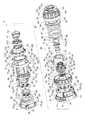
図1は、電動工具の一例である震動ドライバドリルを示す縦断面図、図2はその分解斜視図で、震動ドライバドリル1は、本体ハウジング2内の後部(図1の右側を前方とする。)にモータ3を収容し、そのモータ3の前方に、前方へ突出するスピンドル6を備えたギヤアッセンブリ5を組み付けて、モータ3の出力軸4の回転をスピンドル6に伝達するもので、スピンドル6の前端には、先端でビットを把持可能なドリルチャック7が設けられている。Hereinafter, embodiments of the present invention will be described with reference to the drawings.
FIG. 1 is a longitudinal sectional view showing a vibration driver drill as an example of an electric tool, FIG. 2 is an exploded perspective view thereof, and the
モータ3の前方には、出力軸4を軸支するモータブラケット8が組み付けられており、ギヤアッセンブリ5は、モータブラケット8に連結される筒状の第1ギヤケース9と、その第1ギヤケース9の前方に組み付けられ、大径部11と小径部12との二段筒形状を有する第2ギヤケース10とから形成されている。この第1、第2ギヤケース9,10は、第1ギヤケース9の前部外周面に突設された4つのボス13,13・・をネジ14,14・・によって第2ギヤケース10の後面に螺着することで、互いの結合がなされる。ギヤアッセンブリ5は、第2ギヤケース10の大径部11の後端外周面に突設された4つのボス15,15・・をネジ15a,15a・・(図5,6等に図示)で本体ハウジング2の前端に螺着することで、本体ハウジング2と結合されている。 A
ギヤアッセンブリ5の内部には、インターナルギヤ23A,23B,23C内で公転する複数の遊星ギヤ22,22・・を支持するキャリア21A,21B,21Cを、軸方向に三段配置してなる遊星歯車減速機構20が収容されて、モータ3の出力軸4が一段目の遊星ギヤ22に噛合している。
ここで、モータブラケット8の上下位置には、それぞれ左右方向に所定間隔をおいて前方へ突設され、左右同士で対向する透孔25を穿設した一対の結合板24,24が形成されている。一方、第1ギヤケース9の後端外周面の上下位置には、左右幅が結合板24,24の間隔に合致し、左右方向に貫通孔27を形成した突部26,26が接線方向に突設されている。モータブラケット8と第1ギヤケース9とは、図3にも示すように、上下の結合板24,24間に上下の突部26,26をそれぞれ嵌合させた状態で、出力軸4を中心とする点対称位置に配置される一対のピン28,28を左右方向から透孔25及び貫通孔27にそれぞれ貫通させることで互いに連結される。Inside the
Here, at the upper and lower positions of the
また、モータブラケット8の前面に位置する一段目のインターナルギヤ23Aの上下には、ピン28の間隔に合わせた上下一対の面取部29,29と、その後方で面取部29と直交して半径方向に突出するフランジ部30,30とが形成されている。モータブラケット8と第1ギヤケース9との連結状態で上下のピン28,28は、フランジ部30,30の前方で面取部29,29に沿って第1ギヤケース9を貫通している。よって、インターナルギヤ23Aは、ピン28と面取部29との嵌合によって回転規制され、ピン28とフランジ部30とによって前後方向での位置決めがされることになる。31は、モータブラケット8とインターナルギヤ23Aとの間に介在されたワッシャーである。 In addition, a pair of upper and lower chamfered
さらに、遊星歯車減速機構20において、二段目のインターナルギヤ23Bは、回転可能且つ軸方向へ前後移動可能となっている。このインターナルギヤ23Bの外周面で前半部分には、周方向へ所定間隔をおいて複数の軸方向の外歯32,32・・が突設されて、後半部分は、周方向に結合溝33が形成されている。第1ギヤケース9内の前部には、内周面にインターナルギヤ23Bの外歯と同じ数の軸方向の内歯35,35・・を突設した結合リング34が保持されている。この結合リング34は、その外周に等間隔で突設した周方向の突条36,36・・を、第1ギヤケース9の前端内周面で軸方向に凹設した規制溝37,37・・に嵌合させることで回転規制されている。 Further, in the planetary gear
一方、インターナルギヤ23Bの外周面で後半部分には、速度切替リング38が外装されている。速度切替リング38は、外周面に設けた突起39,39・・と、第1ギヤケース9の後部内周面で軸方向に形成されたガイド溝40,40・・との嵌合によって前後移動のみ可能で、各突起39の外側から半径方向に挿着される結合ピン41の先端をインターナルギヤ23Bの結合溝33に挿入させている。上方に位置する突起39は、後方へ長く突出する延設部42を有しており、その延設部42の後端上面に突設された連結片43は、本体ハウジング2に前後へスライド可能に設けられた速度切替レバー44に、前後のコイルバネ45,45を介して連結されている。 On the other hand, a
よって、速度切替レバー44を後方へスライドさせると、連結片43を介して速度切替リング38が後退し、結合ピン41を介してインターナルギヤ23Bが、二段目の遊星ギヤ22との噛合を保ったまま一段目のキャリア21Aの外周に設けた噛み合い歯46にも噛合する。よって、二段目の減速がキャンセルされる高速モードとなる。逆に速度切替レバー44を前方へスライドさせると、速度切替リング38と共にインターナルギヤ23Bもキャリア21Aから離れて前進し、二段目の遊星ギヤ22との噛合を保ったまま、外歯32を結合リング34の内歯35に噛合させる。よって、二段目の減速が機能する低速モードとなる。 Therefore, when the
そして、ここでは第2ギヤケース10の小径部12の内側に、スピンドル6に軸方向への震動を付与する震動機構50が設けられ、小径部12の外側に、スピンドル6への所定の負荷でスピンドル6へのトルク伝達を遮断するクラッチ機構90が設けられて、後述する切替操作により、スピンドル6が回転しながら震動する震動ドリルモード、スピンドル6が回転のみ行うドリルモード、所定の負荷でスピンドル6へのトルク伝達を遮断するクラッチモード(ドライバモード)がそれぞれ選択可能となっている。以下、各機構について説明する。 Here, a
まず、震動機構50において、スピンドル6は、小径部12内で前後のボールベアリング16,17によって軸支されると共に、その後端が三段目のキャリア21Cと一体のロックカム51にスプライン結合されて、軸方向へ前後移動可能となっている。52は、小径部12内でロックカム51の前方から被着されるキャップである。
但し、スピンドル6は、その前方寄りに形成されたフランジ53とボールベアリング17との間で外装されたコイルバネ54によって、常態ではボールベアリング17の後方位置で外装された止め輪55がボールベアリング17に当接する前進位置に付勢されている。56は、小径部12の前端に嵌入されてボールベアリング17を位置決めするスペーサである。First, in the
However, the
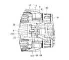
また、スピンドル6におけるボールベアリング16,17間には、前方からリング状の第1カム57、第2カム58が夫々同軸で外装されている。第1カム57は、その後面に、周方向に連続する第1カム歯59,59・・を放射状に形成し、スピンドル6に固着されている。第2カム58は、第1カム歯59と対向する前面に同じ形状の第2カム歯60,60・・を形成してスピンドル6に遊挿されて、前端外周にはフランジ61が周設されると共に、その後方には、図7にも示すように、周方向に等間隔をおいた3つの噛み合い突起62,62・・が突設されている。
さらに、第2カム58の前方で小径部12の内周面には、リング状の段部63が突設されており、第2カム58の後方には、図6にも示すように、小径部12内に固定されたストッパ板64の前面で複数のスチールボール65,65・・・・を介してワッシャー66が保持されている。よって、第2カム58は、段部63とワッシャー66との間で軸方向の移動を規制されることになる。Further, between the
Further, a ring-shaped stepped
一方、小径部12内で第2カム58の外側には、第2カム58の径と略同径のスライドリング67が収容されている。このスライドリング67には、図6,7にも示すように、周方向に等間隔をおいた3つの規制突起68,68・・が、半径方向でリングの内外へ突出するように一体形成されて、各規制突起68の外側への突出部分が、小径部12の内面に形成された軸方向の案内溝69にそれぞれ嵌合している。これによりスライドリング67は、回転規制された状態で小径部12内を前後移動可能となっている。各規制突起68には、半径方向に連結孔70がそれぞれ穿設されて、内側への突出部分は、中心側へ行くほど周方向の厚みが小さくなるテーパ形状となっている。このスライドリング67と第1、第2カム57,58とでカム機構を形成している。 On the other hand, a
また、小径部12において規制突起68が嵌合する各案内溝69には、前後に伸びる長孔71がそれぞれ穿設されて、各長孔71を小径部12の半径方向に貫通する連係ピン72の内端部が、規制突起68の連結孔70に挿入されている。小径部12の外周で長孔71から突出する連係ピン72の後方には、ワッシャー73が外装されると共に、その後方で小径部12の根元には、コイルバネ74が外装されている。よって、連係ピン72にはワッシャー73を介してコイルバネ74の付勢力が加わるため、連係ピン72及びこれと連結されるスライドリング67は前方へ付勢されることになる。 In addition, each
但し、連係ピン72の外側で小径部12には、止め輪75によって前方への移動を規制された筒状の震動切替カム76が回転可能に外装されて、震動切替カム76の前端内周に周設したカム突条77に、連係ピン72の外端部が当接して前方への移動を規制している。このカム突条77の後端縁で周方向に等間隔をおいた3箇所には、図9にも示すように、台形状の係合凹部78,78・・が形成されている。 However, a cylindrical
よって、震動切替カム76を、係合凹部78と連係ピン72とが同じ位相となる第1の回転位置に回転させると、連係ピン72が係合凹部78に係合する前進位置となる。一方、震動切替カム76を、係合凹部78が連係ピン72からずれる位相となる第2の回転位置に回転させると、連係ピン72が係合凹部78から離脱してカム突条77の後端縁に乗り上がって係止する後退位置となる。連係ピン72の前進位置では、スライドリング67も前進して第2カム58のフランジ61に当接し、第2カム58の噛み合い突起62の間に規制突起68を位置させて第2カム58の回転を規制する(第1のスライド位置)。一方、連係ピン72の後退位置では、スライドリング67も後退して噛み合い突起62の間から規制突起68を退避させて第2カム58の回転をフリーとする(第2のスライド位置)。 Therefore, when the
この震動切替カム76の回転は、第2ギヤケース10の大径部11に回転可能に装着されたモード切替リング79によって行われる。このモード切替リング79は、前方に大径部11と略同径の操作部80を、後方に大径部11に内挿する小径の内挿部81をそれぞれ有する二段径で、内挿部81の外周には、周方向に等間隔をおいて3つの嵌合溝82,82・・が軸方向に形成されている。同じく嵌合溝82と同じ位相で震動切替カム76の後端には、3つの切欠き83,83・・が形成されている。 The
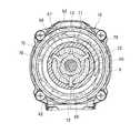
一方、第2ギヤケース10の大径部11と小径部12との間を繋ぐ閉塞部18の前面には、図5に示すように、周方向に所定長さを有する3つの収容凹部84,84・・が凹設されて、各収容凹部84に、両端を前方へ向けたコ字状の連結棒85が、閉塞部18の半径方向に沿って配置されて、外側の端部86を内挿部81の嵌合溝82に嵌合させる一方、内側の端部87を震動切替カム76の切欠き83に係止させている。よって、操作部80を把持してモード切替リング79を回転させると、連結棒85を介して内側の震動切替カム76が同時に回転し、連係ピン72及びスライドリング67を前後動させることができる。 On the other hand, on the front surface of the closing
次に、クラッチ機構90について説明する。
まず、モード切替リング79の前方で小径部12には、内周に雌ネジ部92を形成したクラッチリング91が回転可能に外装されると共に、その内側に、外周に雄ネジ部94を形成したスプリングホルダ93が、クラッチリング91に螺合した状態で外装されている。このスプリングホルダ93は、内周に形成した突起95を小径部12の外周に形成した軸方向の溝96に嵌合させて、回転規制された状態で軸方向に前後移動可能となっている。また、スプリングホルダ93の後方で小径部12には、震動切替カム76よりも内径が大きいコイルバネ97が外装されて、コイルバネ97の前端がスプリングホルダ93に保持される一方、コイルバネ97の後端は、閉塞部18の前面に設けたワッシャー98に当接している。このワッシャー98は、連結棒85の内外の端部86,87間を通過する格好で閉塞部18の前面に当接して、モード切替リング79の回転に伴う連結棒85の移動と干渉しないようになっている。Next, the
First, a
さらに、閉塞部18には、周方向に等間隔をおいて6本の係合ピン99,99・・が前後移動可能に貫通して、前端をワッシャー98に当接させる一方、後端を、三段目のインターナルギヤ23Cの前面に当接させている。インターナルギヤ23Cの前面には、係合ピン99の間に位置する台形状のカム突起100,100・・が周方向へ等間隔で当接されている。
よって、係合ピン99は、ワッシャー98を介して伝わるコイルバネ97の付勢力によってインターナルギヤ23Cの前面に押圧され、周方向でカム突起100と係合してインターナルギヤ23Cの回転規制を行う。クラッチリング91を回転操作すると、スプリングホルダ93が軸方向へネジ送りされてコイルバネ97を軸方向に伸縮させて押圧力を調整することになる。クラッチリング91の前側で小径部12には、止め輪101によってクリック板102が固定されて、そのクリック片103がクラッチリング91の前面に形成された複数の凹部104,104・・に係脱することで、クラッチリング91を回転操作する際のクリック作用が得られるようになっている。Further, in the closing
Therefore, the
一方、第1ギヤケース9の規制溝37を除く前端内周面には、図4にも示すように、前端から軸方向の保持溝105,105・・が、周方向へ所定間隔をおいて形成されて、各保持溝105にラバーピン106が保持されている。このラバーピン106は、その内側に位置する結合リング34の外周面とインターナルギヤ23Cの外周面とに跨って当接して、第1ギヤケース9と結合リング34及びインターナルギヤ23Cとの間で圧縮されている。これによりインターナルギヤ23Cには、ラバーピン106によって回転方向への抵抗が常に加わることになる。 On the other hand, on the inner peripheral surface of the front end excluding the
さらに、閉塞部18において、収容凹部84の間には、図8にも示すように、前方から規制ピン107が遊挿されている。この規制ピン107は、前端に大径の頭部108を有して後端を閉塞部18の後方へ突出させて、インターナルギヤ23Cの外歯32に係合させるもので、閉塞部18と頭部108との間で規制ピン107に外装されたコイルバネ109によって前方へ付勢されている。規制ピン107の前方には、モード切替リング79の内挿部81が位置して頭部108が当接するようになっており、内挿部81の後端縁には、規制ピン107の位相に合わせた台形状の切欠き110,110・・が形成されている。すなわち、モード切替リング79の回転操作により、切欠き110を規制ピン107の位相に合わせると、頭部108が切欠き110に嵌合するまで規制ピン107が前進してインターナルギヤ23Cの外歯32から離間し、切欠き110と規制ピン107との位相をずらすと、規制ピン107が切欠き110から内挿部81の後端縁に乗り上がることで後退し、外歯32と係合する。この係合によりインターナルギヤ23Cの回転はロックされる。 Further, as shown in FIG. 8, the
以上の如く構成された震動ドライバドリル1においては、以下に説明するように、モード切替リング79の回転操作によって、3つの動作モードが選択可能となる。
まず、モード切替リング79の切欠き110が規制ピン107と同じ位相となる第1の切替位置(連結棒85は図5に二点鎖線で示す(A)の位置)では、前述のように規制ピン107は前進してインターナルギヤ23Cの回転ロックを解除する。このとき、モード切替リング79は連結棒85を介して震動切替カム76を、係合凹部78が連係ピン72からずれる第2の回転位置に回転させる。よって、第2カム60は回転フリー状態、インターナルギヤ23Cはコイルバネ97の押圧力で回転規制される状態となり、クラッチリング91の回転操作によって係合ピン99への押圧力(最大トルク)が変更可能なクラッチモードとなる。In the
First, at the first switching position where the
このクラッチモードでモータ3を駆動させてスピンドル6を回転させると、ドリルチャック7に装着したドライバビットでネジ締め等を行うことができる。ここで、インターナルギヤ23Cには、ラバーピン106によって回転方向への抵抗が付与されているため、設定されるコイルバネ97の押圧力が小さい場合、モータ3の起動トルクが瞬間的に加わることがあっても、インターナルギヤ23Cの空転は抑制され、クラッチの早切れは生じない。
ネジ締めが進んでスピンドル6への負荷が、インターナルギヤ23Cを固定するコイルバネ97の押圧力を越えると、インターナルギヤ23Cのカム突起100が係合ピン99を前方へ押し出して相対的にカム突起100を乗り越えさせ、インターナルギヤ23Cを空転させてネジ締めを終了させる(クラッチ作動)。このときはラバーピン106による抵抗があってもインターナルギヤ23Cは空転する。なお、ドライバビットのネジへの押し付けによってスピンドル6が後退し、第1カム57が第2カム58と当接することがあっても、第2カム58は回転フリー状態であるため、第1カム57と共に回転する。よって、スピンドル6に震動は発生しない。When the
When the screw tightening progresses and the load on the
次に、クラッチモードからモード切替リング79を前方から見て左回転させた第2の切替位置(連結棒85は図5に実線で示す(B)の位置)では、切欠き110は図8に示すように規制ピン107からずれる位相となるため、規制ピン107は内挿部81の後端縁に乗り上がって後退し、インターナルギヤ23Cの回転をロックする。一方、このときも震動切替カム76は、図9に示すように係合凹部78が連係ピン72からずれる第2の回転位置にあるため、第2カム58はフリー状態のままである。よって、コイルバネ97の押圧力の大小にかかわらずインターナルギヤ23Cの回転は常にロックされるドリルモードとなる。
このドリルモードでスピンドル6を回転させると、スピンドル6への負荷にかかわらずスピンドル6の回転は継続する。勿論スピンドル6に震動は発生しない。Next, in the second switching position in which the
When the
そして、ドリルモードからモード切替リング79をさらに左回転させた第3の切替位置(連結棒85は図5に二点鎖線で示す(C)の位置及び図11の実線位置)では、図14に示すように切欠き110が規制ピン107からさらに離れるのみで位相がずれた状態は変わらないため、インターナルギヤ23Cの回転はロックされる。一方、震動切替カム76は、係合凹部78が連係ピン72と同じ位相となる第1の回転位置に達するため、図12及び図15に示すように、コイルバネ74の付勢によって連係ピン72が係合凹部78に係合して、図10及び図12,13に示すようにスライドリング67が前進し、第2カム58を回転規制する。よって、スピンドル6の後退位置で第1カム57と第2カム58とが当接する震動ドリルモードとなる。 Then, in the third switching position where the
この震動ドリルモードでドリルビット等を被加工材に押し当ててスピンドル6を後退させた状態で回転させると、スピンドル6と一体回転する第1カム57の第1カム歯59が、回転規制される第2カム58の第2カム歯60と干渉するため、スピンドル6に軸方向の震動が発生する。なお、インターナルギヤ23Cの回転はロックされているため、スピンドル6への負荷にかかわらずスピンドル6の回転は継続することになる。 In this vibration drill mode, when a drill bit or the like is pressed against a workpiece to rotate the
なお、第2ギヤケース10の大径部11の外周には、図2に示すように各動作モードの選択の目印111が表記されており、モード切替リング79には、各動作モードを示す3つのマーク112,112・・が表記されている。よって、目印111にマーク112を合わせることで所望の動作モードが得られる。 In addition, on the outer periphery of the large-
このように上記形態の震動ドライバドリル1によれば、モータブラケット8と第1ギヤケース9との結合を、モータブラケット8と第1ギヤケース9とに跨って貫通する一対のピン28,28によって行うと共に、ピン28,28を、遊星歯車減速機構20の一段目のインターナルギヤ23Aに係合させてインターナルギヤ23Aの回転規制及び軸方向での位置決めを行うようにしたことで、モータブラケット8と第1ギヤケース9との結合を、インターナルギヤ23Aの組付けと連係させて行うことができる。よって、第1ギヤケース9の形状が単純化して剛性も確保することができる。 As described above, according to the
特にここでは、ピン28は、モータ3の出力軸4を中心とした点対称位置に一対設けているので、モータブラケット8と第1ギヤケース9とをより確実に一体化することができる。
また、インターナルギヤ23Aの側面に、ピン28,28に沿った面取部29,29を形成し、面取部29,29の後方に、面取部29と直交してインターナルギヤ23Aの半径方向に突出するフランジ部30,30を形成して、ピン28と面取部29との当接によりインターナルギヤ23Aの回転規制を、ピン28とフランジ部30との当接によりインターナルギヤ23Aの軸方向での位置決めをそれぞれ行うようにしているので、一本のピン28でインターナルギヤ23Aの回転規制と軸方向の位置決めとが同時に行える合理的な構成となる。In particular, here, the pair of
Further, chamfered
なお、上記形態では、ピンを左右方向に貫通させてモータブラケットとギヤケースとの結合を図っているが、上下方向に貫通させて結合させてもよい。また、上記形態ではモータブラケットに設けた結合板の間にギヤケースの突部を介在させてピンを貫通させているが、これと逆に、モータブラケットに突部を、ギヤケースに結合板をそれぞれ設けても差し支えない。勿論結合板や突部の形状は適宜変更可能であるし、結合時に一体性が得られればピンは一本のみとしても差し支えない。
さらに、モータブラケットやギヤケース自体の形状も上記形態に限らない。例えばギヤケースは上記形態のような2分割構造でなく、両者が一体形成されるものであってもよい。In the above embodiment, the pin is penetrated in the left-right direction to connect the motor bracket and the gear case. However, the pin may be penetrated in the up-down direction to be coupled. Further, in the above embodiment, the projection of the gear case is interposed between the coupling plates provided on the motor bracket, but the pin is penetrated, but conversely, the projection may be provided on the motor bracket and the coupling plate may be provided on the gear case. There is no problem. Of course, the shape of the coupling plate and the protrusions can be changed as appropriate, and only one pin may be used as long as the unity is obtained at the time of coupling.
Furthermore, the shape of the motor bracket and the gear case itself is not limited to the above-described form. For example, the gear case is not a two-part structure as in the above embodiment, but may be formed integrally with both.
一方、ピンとインターナルギヤとの係合も、面取部に代えて凹溝としたり、面取部やフランジ部に代えてピンをインターナルギヤにその接線方向で貫通させたり等、回転規制と位置決めとが可能であれば上記形態に限定されない。
そして、電動工具としては震動ドライバドリルに限らず、モータとギヤケースとをモータブラケットを介して結合する構造を具備するものであれば、電動ドライバや電動ドリル、インパクトドライバ等の他のタイプであっても本発明は採用可能である。On the other hand, the engagement between the pin and the internal gear is not limited to the chamfered portion, but a concave groove, or the pin is allowed to penetrate the internal gear in the tangential direction instead of the chamfered portion or the flange portion. If positioning is possible, it is not limited to the said form.
The electric tool is not limited to the vibration driver drill, and may be other types such as an electric driver, an electric drill, an impact driver, and the like as long as the electric tool has a structure in which a motor and a gear case are coupled via a motor bracket. The present invention can also be employed.
1・・震動ドライバドリル、2・・本体ハウジング、3・・モータ、4・・出力軸、5・・ギヤアッセンブリ、6・・スピンドル、7・・ドリルチャック、8・・モータブラケット、9・・第1ギヤケース、10・・第2ギヤケース、11・・大径部、12・・小径部、20・・遊星歯車減速機構、23A〜23C・・インターナルギヤ、24・・結合板、26・・突部、28・・ピン、29・・面取部、30・・フランジ部、34・・結合リング、50・・震動機構、57・・第1カム、58・・第2カム、67・・スライドリング、71・・長孔、72・・連係ピン、74・・コイルバネ、76・・震動切替カム、78・・係合凹部、79・・モード切替リング、80・・操作部、85・・連結棒、90・・クラッチ機構、91・・クラッチリング、97・・コイルバネ、99・・係合ピン、105・・保持溝、106・・ラバーピン。 1 ....
Claims (3)
Translated fromJapanese前記モータブラケットと前記ギヤケースとの結合を、前記モータブラケットと前記ギヤケースとに貫通する少なくとも一本のピンによって行うと共に、前記ピンを、前記遊星歯車減速機構の一段目のインターナルギヤに係合させて前記インターナルギヤの回転規制及び軸方向での位置決めを行うことを特徴とする電動工具。A power tool in which a cylindrical gear case containing a planetary gear reduction mechanism is disposed in front of the motor, and the motor and the gear case are coupled via a cylindrical motor bracket attached to the motor,
The motor bracket and the gear case are coupled by at least one pinpenetrating the motor bracket and the gear case,and the pin is engaged with a first internal gear of the planetary gear reduction mechanism. A power tool characterized by performing rotation restrictionand positioning in the axial direction of the internal gear.
Priority Applications (5)
| Application Number | Priority Date | Filing Date | Title |
|---|---|---|---|
| JP2011083935AJP5649500B2 (en) | 2011-04-05 | 2011-04-05 | Electric tool |
| EP12157743.1AEP2508302B1 (en) | 2011-04-05 | 2012-03-01 | Power tool |
| US13/409,761US8684882B2 (en) | 2011-04-05 | 2012-03-01 | Power tool |
| CN201210094049.9ACN102729222B (en) | 2011-04-05 | 2012-03-31 | Power tool |
| RU2012113211/02ARU2601529C2 (en) | 2011-04-05 | 2012-04-04 | Power tool |
Applications Claiming Priority (1)
| Application Number | Priority Date | Filing Date | Title |
|---|---|---|---|
| JP2011083935AJP5649500B2 (en) | 2011-04-05 | 2011-04-05 | Electric tool |
Publications (3)
| Publication Number | Publication Date |
|---|---|
| JP2012218088A JP2012218088A (en) | 2012-11-12 |
| JP2012218088A5 JP2012218088A5 (en) | 2014-01-09 |
| JP5649500B2true JP5649500B2 (en) | 2015-01-07 |
Family
ID=45808222
Family Applications (1)
| Application Number | Title | Priority Date | Filing Date |
|---|---|---|---|
| JP2011083935AActiveJP5649500B2 (en) | 2011-04-05 | 2011-04-05 | Electric tool |
Country Status (5)
| Country | Link |
|---|---|
| US (1) | US8684882B2 (en) |
| EP (1) | EP2508302B1 (en) |
| JP (1) | JP5649500B2 (en) |
| CN (1) | CN102729222B (en) |
| RU (1) | RU2601529C2 (en) |
Families Citing this family (17)
| Publication number | Priority date | Publication date | Assignee | Title |
|---|---|---|---|---|
| DE102008041599A1 (en) | 2008-08-27 | 2010-03-04 | Robert Bosch Gmbh | Switchable transmission in a hand tool |
| JP5628079B2 (en)* | 2011-04-05 | 2014-11-19 | 株式会社マキタ | Vibration driver drill |
| JP2012218089A (en)* | 2011-04-05 | 2012-11-12 | Makita Corp | Power tool |
| JP5938652B2 (en)* | 2012-05-10 | 2016-06-22 | パナソニックIpマネジメント株式会社 | Electric tool |
| JP6013929B2 (en)* | 2013-01-22 | 2016-10-25 | 株式会社マキタ | Electric tool |
| US10040178B2 (en) | 2014-05-27 | 2018-08-07 | Makita Corporation | Power tool and rotary impact tool |
| JP6491904B2 (en)* | 2015-02-19 | 2019-03-27 | 株式会社マキタ | Electric tool |
| US20180062479A1 (en)* | 2016-08-24 | 2018-03-01 | Cts Corporation | Modular Vehicle Engine Component Actuator |
| JP7049929B2 (en) | 2018-06-06 | 2022-04-07 | 株式会社マキタ | Power tools and electric vibration driver drills |
| JP7182998B2 (en)* | 2018-11-08 | 2022-12-05 | 株式会社マキタ | Electric tool |
| US11267118B2 (en) | 2018-11-08 | 2022-03-08 | Makita Corporation | Electric power tool |
| US11453109B2 (en)* | 2019-01-09 | 2022-09-27 | Makita Corporation | Power tool |
| JP7382197B2 (en)* | 2019-01-09 | 2023-11-16 | 株式会社マキタ | Electric tool |
| JP7263155B2 (en)* | 2019-06-28 | 2023-04-24 | 株式会社マキタ | Electric tool |
| CN212553188U (en)* | 2020-07-09 | 2021-02-19 | 株式会社牧田 | Detachable dust cover for belt grinder and belt grinder |
| EP4059665A1 (en) | 2020-12-21 | 2022-09-21 | Techtronic Cordless GP | Power tool with gear assembly |
| WO2023064628A1 (en)* | 2021-10-15 | 2023-04-20 | Hubbell Incorporated | Portable hand-held hydraulic tools |
Family Cites Families (17)
| Publication number | Priority date | Publication date | Assignee | Title |
|---|---|---|---|---|
| SU1009748A1 (en)* | 1981-02-03 | 1983-04-07 | Предприятие П/Я А-7332 | Portable nut or screw driver |
| SU965754A1 (en)* | 1981-03-26 | 1982-10-15 | Предприятие П/Я Р-6271 | Apparatus for unscrewing and screwing-on nuts on motor rotor shaft |
| JPS5953164A (en)* | 1982-09-20 | 1984-03-27 | 松下電工株式会社 | Electric driver |
| JPS62166971A (en)* | 1986-01-20 | 1987-07-23 | 松下電工株式会社 | Electric driver |
| SE503889C2 (en)* | 1994-10-31 | 1996-09-23 | Atlas Copco Tools Ab | Reversible nut wrench |
| JPH10329056A (en)* | 1997-05-27 | 1998-12-15 | Matsushita Electric Works Ltd | Power tool |
| JP2000320438A (en)* | 1999-05-12 | 2000-11-21 | Mitsubishi Electric Corp | Starting motor |
| US6676557B2 (en)* | 2001-01-23 | 2004-01-13 | Black & Decker Inc. | First stage clutch |
| DE10149382C1 (en)* | 2001-10-06 | 2003-05-08 | Bosch Gmbh Robert | Device for switching a two-stage transmission of a power tool |
| CN1643270A (en)* | 2002-01-25 | 2005-07-20 | 布莱克-德克尔公司 | Power drill/driver |
| US7066691B2 (en) | 2002-01-25 | 2006-06-27 | Black & Decker Inc. | Power drill/driver |
| JP4084319B2 (en)* | 2004-02-23 | 2008-04-30 | リョービ株式会社 | Electric tool |
| JP4405900B2 (en)* | 2004-03-10 | 2010-01-27 | 株式会社マキタ | Impact driver |
| EP1970165A1 (en)* | 2007-03-12 | 2008-09-17 | Robert Bosch Gmbh | A rotary power tool operable in a first speed mode and a second speed mode |
| DE102009013108A1 (en)* | 2009-03-13 | 2010-09-16 | Metabowerke Gmbh | Electric motor driven screwing or drilling tool |
| CN102148548B (en)* | 2010-02-09 | 2015-05-06 | 德昌电机(深圳)有限公司 | Motor component used for medical appliance |
| CN201769185U (en)* | 2010-08-18 | 2011-03-23 | 宁波新港工具有限公司 | Gear box for electric tool |
- 2011
- 2011-04-05JPJP2011083935Apatent/JP5649500B2/enactiveActive
- 2012
- 2012-03-01EPEP12157743.1Apatent/EP2508302B1/enactiveActive
- 2012-03-01USUS13/409,761patent/US8684882B2/enactiveActive
- 2012-03-31CNCN201210094049.9Apatent/CN102729222B/enactiveActive
- 2012-04-04RURU2012113211/02Apatent/RU2601529C2/enactive
Also Published As
| Publication number | Publication date |
|---|---|
| US20120258832A1 (en) | 2012-10-11 |
| EP2508302A1 (en) | 2012-10-10 |
| RU2601529C2 (en) | 2016-11-10 |
| JP2012218088A (en) | 2012-11-12 |
| CN102729222B (en) | 2014-06-04 |
| CN102729222A (en) | 2012-10-17 |
| RU2012113211A (en) | 2013-10-10 |
| US8684882B2 (en) | 2014-04-01 |
| EP2508302B1 (en) | 2014-01-22 |
Similar Documents
| Publication | Publication Date | Title |
|---|---|---|
| JP5649500B2 (en) | Electric tool | |
| JP5628079B2 (en) | Vibration driver drill | |
| JP2012218089A (en) | Power tool | |
| JP4405900B2 (en) | Impact driver | |
| JP5744669B2 (en) | Electric tool | |
| JP5583500B2 (en) | Impact tool | |
| JP4468786B2 (en) | Impact tools | |
| JP5744639B2 (en) | Electric tool | |
| JP5468570B2 (en) | Impact tool | |
| JP4227028B2 (en) | Screwdriver drill | |
| JP5340881B2 (en) | Impact tool | |
| JP4917408B2 (en) | Electric tool | |
| JP5284898B2 (en) | Impact tool | |
| JP4391921B2 (en) | Vibration drill | |
| JP4824812B2 (en) | Impact tools | |
| JP2012006101A (en) | Impact tool | |
| JP2005249110A (en) | Rotation output device | |
| JP7231329B2 (en) | screw tightening tool | |
| EP2712708B1 (en) | Impact rotation tool | |
| CN107471164B (en) | Torque output tool | |
| CN107471165B (en) | Torsion output tool |
Legal Events
| Date | Code | Title | Description |
|---|---|---|---|
| A521 | Request for written amendment filed | Free format text:JAPANESE INTERMEDIATE CODE: A523 Effective date:20131118 | |
| A621 | Written request for application examination | Free format text:JAPANESE INTERMEDIATE CODE: A621 Effective date:20131118 | |
| A131 | Notification of reasons for refusal | Free format text:JAPANESE INTERMEDIATE CODE: A131 Effective date:20140722 | |
| A521 | Request for written amendment filed | Free format text:JAPANESE INTERMEDIATE CODE: A523 Effective date:20140905 | |
| TRDD | Decision of grant or rejection written | ||
| A01 | Written decision to grant a patent or to grant a registration (utility model) | Free format text:JAPANESE INTERMEDIATE CODE: A01 Effective date:20141014 | |
| A61 | First payment of annual fees (during grant procedure) | Free format text:JAPANESE INTERMEDIATE CODE: A61 Effective date:20141111 | |
| R150 | Certificate of patent or registration of utility model | Ref document number:5649500 Country of ref document:JP Free format text:JAPANESE INTERMEDIATE CODE: R150 | |
| R250 | Receipt of annual fees | Free format text:JAPANESE INTERMEDIATE CODE: R250 | |
| R250 | Receipt of annual fees | Free format text:JAPANESE INTERMEDIATE CODE: R250 | |
| R250 | Receipt of annual fees | Free format text:JAPANESE INTERMEDIATE CODE: R250 | |
| R250 | Receipt of annual fees | Free format text:JAPANESE INTERMEDIATE CODE: R250 | |
| R250 | Receipt of annual fees | Free format text:JAPANESE INTERMEDIATE CODE: R250 | |
| R250 | Receipt of annual fees | Free format text:JAPANESE INTERMEDIATE CODE: R250 | |
| R250 | Receipt of annual fees | Free format text:JAPANESE INTERMEDIATE CODE: R250 | |
| R250 | Receipt of annual fees | Free format text:JAPANESE INTERMEDIATE CODE: R250 |