JP5649460B2 - Recording head, image forming apparatus, and liquid ejection apparatus - Google Patents
Recording head, image forming apparatus, and liquid ejection apparatusDownload PDFInfo
- Publication number
- JP5649460B2 JP5649460B2JP2011002993AJP2011002993AJP5649460B2JP 5649460 B2JP5649460 B2JP 5649460B2JP 2011002993 AJP2011002993 AJP 2011002993AJP 2011002993 AJP2011002993 AJP 2011002993AJP 5649460 B2JP5649460 B2JP 5649460B2
- Authority
- JP
- Japan
- Prior art keywords
- recording
- data
- block
- counter circuit
- individual
- Prior art date
- Legal status (The legal status is an assumption and is not a legal conclusion. Google has not performed a legal analysis and makes no representation as to the accuracy of the status listed.)
- Expired - Fee Related
Links
Images


Landscapes
- Ink Jet (AREA)
- Particle Formation And Scattering Control In Inkjet Printers (AREA)
Description
Translated fromJapanese本発明は、記録ヘッド、画像形成装置及び液体吐出装置に係り、特に、複数の記録素子が配列された記録素子列を有する記録ヘッドにおける各記録素子を駆動制御するためのデータ転送技術に関する。 The present invention relates to a recording head, an image forming apparatus, and a liquid ejecting apparatus, and more particularly to a data transfer technique for driving and controlling each recording element in a recording head having a recording element array in which a plurality of recording elements are arranged.
インク吐出のための吐出エネルギーを発生させる手段として発熱抵抗素子からなるヒータを用いたインクジェットヘッドは、各ノズル(インク吐出口)に対応する発熱抵抗素子を吐出データ(記録データ)に応じて選択的に駆動することにより、所望のノズルからインク滴を吐出させる。この吐出されたインク滴を記録媒体に付着させることにより、記録媒体上にドットが形成され、記録印刷が行われる(特許文献1参照)。 Ink jet heads using heaters composed of heating resistance elements as means for generating ejection energy for ink ejection selectively select heating resistance elements corresponding to each nozzle (ink ejection port) according to ejection data (recording data). Ink droplets are ejected from a desired nozzle. By attaching the ejected ink droplets to the recording medium, dots are formed on the recording medium, and recording printing is performed (see Patent Document 1).
図18は、インクジェットヘッド駆動回路の構成図である。記録ヘッド800は、各ノズルに対応した複数の発熱抵抗素子802を備え、各発熱抵抗素子802にはそれぞれトランジスタ等のスイッチ素子804が接続されている。記録データは、ヘッド外部よりシリアルデータで入力される。シリアルデータはシフトレジスタ部810に転送され、クロック信号に同期してパラレルデータに展開される。パラレル変換されたデータは各発熱抵抗素子802に対応した記録データであり、ラッチ部812にてデータが保持される。この後、セレクタ部814にて所定の時間をONすると、対応するスイッチ素子804がONし、発熱抵抗素子802に電源806から電流が流れ、インク吐出に必要な熱が発生する。この動作によりインクが記録ヘッド800のノズルから吐出される。 FIG. 18 is a configuration diagram of an inkjet head drive circuit. The
近年、インクジェット式プリンタは年々高解像度化している。これに伴い、記録ヘッドのノズルの配置密度は高密度化し、吐出されるインク滴(液滴)の大きさは数pl(ピコリットル)と、益々微小化する傾向にある。また同時に、記録の高速化も進んできている。記録解像度を高めるために、1画素の領域に付与するインク量を調整し、互いに異なる複数サイズのドットによって1画素を記録形成する多値プリンタも提案されている(特許文献2)。多値プリンタは、1画素領域内に付与するインク量が多いほど、大きなドットが形成される。すなわち、1画素領域内に比較的多量のインク滴が付与されることによって比較的大きなドットが1画素の領域内に形成される。 In recent years, the resolution of ink jet printers has been increasing year by year. Along with this, the arrangement density of the nozzles of the recording head has been increased, and the size of the ejected ink droplets (droplets) tends to become increasingly smaller, several pl (picoliter). At the same time, the recording speed has been increased. In order to increase the recording resolution, a multi-value printer that adjusts the amount of ink applied to an area of one pixel and records and forms one pixel with dots of different sizes has been proposed (Patent Document 2). In the multi-value printer, a larger dot is formed as the amount of ink applied in one pixel region is larger. That is, by applying a relatively large amount of ink droplets in one pixel region, a relatively large dot is formed in the one pixel region.
ただし、一般に、ヒータ(発熱抵抗素子)を用いたインク液の加熱により液滴を吐出させるサーマルジェット方式の記録ヘッドは、同一のノズル孔でインク噴出量を調整することが難しい。そのため、このような多値プリンタでは、ノズル孔のサイズを異ならせた複数種類のノズル列を備えた記録ヘッドが採用され、多種サイズのノズル孔からインクを吐出させて1画素の記録が行われる。 However, in general, it is difficult to adjust the amount of ink ejected from the same nozzle hole in a thermal jet type recording head that ejects liquid droplets by heating ink liquid using a heater (heating resistance element). For this reason, in such a multi-value printer, a recording head having a plurality of types of nozzle rows with different nozzle hole sizes is employed, and ink is ejected from nozzle holes of various sizes to record one pixel. .
例えば、図19に示すように、小液滴のインクを吐出する吐出孔840が高密度に配置された高解像度用のノズル列850と、高速で記録するために大液滴インクを吐出する吐出孔842が低密度に配置された高速用のノズル列852と、中液滴のインクを吐出する吐出孔844が中密度に配置されたノズル列854と、を備えた記録ヘッドが提案されている。このような複数のノズル列を備えた記録ヘッドは、記録に使用するノズルサイズ(ノズル列)を選択しつつ、所望のタイミングでインク吐出を行う必要があり、印刷速度向上のために各ノズルの吐出データを高速に転送する必要がある。 For example, as shown in FIG. 19, a high-
特許文献1及び2は、複数の記録素子に対して高速に効率良く吐出データを転送する手法を提案している。特許文献1に記載の技術は、記録素子を高速駆動するために、次のラインの画像データ転送開始までに画像データを記録ヘッドに高速転送することを課題としたものである。この課題に対し、同文献1では、記録ヘッドに駆動可能な複数の記録素子をブロック分けし、そのブロックを選択するブロック選択信号とブロック内の記録素子を選択駆動する駆動信号を画像データに対応して各記録素子に出力する記録制御回路を備え、記録制御回路に入力するための画像データを入力手段にて外部から画像データとブロック選択データとを連続した複数ビットのバス形式で受け取るようにした特徴を持たせている。
具体的な実施形態として、画像データ信号の先頭ビットにブロック選択用データ、それ以降に画像データが連続的にバス形式で送られ、バスの第1ビットはパラレルデータとして受け、デコードによりブロック選択信号に変換される一方、画像データはバス幅のビット単位に順次ブロック内の記録素子を選択駆動する信号に変換され、記録素子に出力されるというものである。 As a specific embodiment, block selection data is sent to the first bit of the image data signal, and image data is continuously sent in the bus format thereafter, the first bit of the bus is received as parallel data, and the block selection signal is decoded. On the other hand, the image data is sequentially converted into signals for selectively driving the recording elements in the block in units of bits of the bus width, and output to the recording elements.
このようなデータ転送手段によって、シフトレジスタの段数が記録素子の総数に対して少なくなり回路構成を簡略化することが可能となり、その結果、記録装置本体からの画像データや制御信号等の転送を少ない信号線の数でより高速化することができるという効果を得ている。 By such data transfer means, the number of stages of the shift register is reduced with respect to the total number of recording elements, and the circuit configuration can be simplified. As a result, image data, control signals, etc. from the recording apparatus main body can be transferred. The effect is that the speed can be further increased with a small number of signal lines.
特許文献2に記載の技術は、異なる配列密度で配置された複数の記録素子列を備えた素子基板に関するものであり、高密度配列の記録素子列側の駆動速度低下を抑制し、これら各記録素子へ効率良くデータ転送することを課題としている。この課題に対し、同文献2では、異なる数の複数素子を備えた第1列のノズル配列と、第1列と長さが等しく相対的に少数の記録素子数である第2列のノズル配列において、第2列は所定数のグループで第1シフトレジスタ、第2列は所定数のグループを第1、第2グループ群に分け、各群を第2、第3シフトレジスタで駆動データを保持する回路を備えることで、異なる配列密度が混在した記録ヘッドへのデータ転送の効率化を可能としている。具体的には、低密度でヒータを配置したヒータ列に対応するシフトレジスタ回路1つが保持するデータのビット数と高密度でヒータを配置したヒータ列に対応するシフトレジスタ回路2つのそれぞれの保持するデータのビット数との差を減らすことで、全てのシフトレジスタ回路が保持するデータのビット数が近いほど、データ転送速度差が少なくなってくるというものである。 The technique described in Patent Document 2 relates to an element substrate including a plurality of recording element arrays arranged at different arrangement densities, and suppresses a decrease in driving speed on the recording element array side in a high-density array, and each of these recording elements An object is to efficiently transfer data to an element. In order to solve this problem, the document 2 discloses a first-row nozzle array having a plurality of different numbers of elements and a second-row nozzle array having a relatively small number of printing elements that are equal in length to the first row. , The second column has a predetermined number of groups as the first shift register, the second column has the predetermined number of groups as the first and second group groups, and each group holds the drive data by the second and third shift registers. By providing such a circuit, it is possible to improve the efficiency of data transfer to a recording head in which different arrangement densities are mixed. Specifically, the number of bits of data held by one shift register circuit corresponding to a heater row in which heaters are arranged at low density and the two shift register circuits corresponding to heater rows in which heaters are arranged at high density are held respectively. By reducing the difference from the number of data bits, the closer the number of data bits held by all the shift register circuits, the smaller the data transfer rate difference.
こうして高密度でヒータを配置したヒータ列へのデータ転送速度が低密度でヒータを配置したヒータ列へのデータ転送速度に比べて極端に遅くなるということを防止している。 Thus, it is possible to prevent the data transfer speed to the heater array in which the heaters are arranged at a high density from becoming extremely slow as compared with the data transfer speed to the heater array in which the heaters are arranged at a low density.
インクジェット印刷を含む画像形成技術の分野では、記録媒体サイズの拡大と共に高解像度化と高速印刷も要求されてきている。これに対応すべき記録ヘッドも長尺のタイプで数千ノズルを越えるものや、それらを記録媒体の搬送方向に向かって垂直に沿って複数個並べることで要求を満たすものも出ている。このような長尺ヘッド或いは複数個並べたヘッドを用いて記録印刷するものは、ヘッドの取り付け位置のバラツキでインク吐出位置がずれ、その結果として記録媒体へのインク着弾もずれてしまうという問題がある。 In the field of image forming technology including ink jet printing, higher resolution and higher speed printing have been demanded as the recording medium size has increased. There are some print heads that can cope with this, such as a long type that exceeds several thousand nozzles, and a print head that meets the requirements by arranging a plurality of them vertically along the direction of conveyance of the print medium. In such a long print head or a print head using a plurality of arranged heads, there is a problem that the ink discharge position is shifted due to variations in the head mounting position, and as a result, ink landing on the recording medium is also shifted. is there.
特に長尺タイプで1列当りのノズル数が多い高解像度の記録ヘッドにおける角度ずれは、ノズル列両端におけるインク着弾位置のずれが大きく、記録品質上問題となる。図20(a)は長尺ヘッドとそのノズル配列の例を示している。図20(b)は長尺ヘッドを構成するヘッドモジュールの取付位置の誤差によって、ノズル列が本来の位置からずれ、インクの着弾位置にずれが発生している様子を模式的に示した部分拡大図である。 In particular, the angular deviation in a high resolution recording head with a long type and a large number of nozzles per row causes a large deviation in ink landing positions at both ends of the nozzle row, which causes a problem in recording quality. FIG. 20A shows an example of a long head and its nozzle arrangement. FIG. 20B is a partially enlarged view schematically showing that the nozzle row is displaced from the original position due to an error in the mounting position of the head module constituting the long head, and the ink landing position is displaced. FIG.
図示のように、複数個のヘッドモジュールを繋ぎ合わせて長尺の記録ヘッドを構成する場合、モジュールの取付位置の誤差によって、モジュール単位で位置誤差が発生する場合もある。このようにノズル列の傾きによって発生する着弾位置ずれ(記録位置のずれ)を記録素子の駆動タイミングによって補正しようとすると、各ノズルの着弾位置を補正するためのデータはノズル(記録素子)毎に必要となる。 As shown in the figure, when a long recording head is formed by connecting a plurality of head modules, a position error may occur in units of modules due to an error in the mounting position of the module. In this way, when the landing position deviation (recording position deviation) caused by the inclination of the nozzle row is to be corrected by the drive timing of the recording element, the data for correcting the landing position of each nozzle is the data for each nozzle (recording element). Necessary.
記録ヘッドの各記録素子に対し、外部からそれぞれの駆動タイミング信号やタイミングデータを転送するには、転送量や端子数、回路数が膨大となり、データ転送時間も要する。 In order to transfer each drive timing signal and timing data from the outside to each recording element of the recording head, the transfer amount, the number of terminals, and the number of circuits are enormous, and a data transfer time is also required.
本発明はこのような事情に鑑みてなされたものであり、複数の記録素子が並ぶ記録素子列の各記録位置を補正するために、各記録素子の駆動タイミングを補正するためのデータを記録素子に効率良くデータ転送することができる記録ヘッド、画像形成装置及び液体吐出装置を提供することを目的とする。 The present invention has been made in view of such circumstances, and in order to correct each recording position of a recording element array in which a plurality of recording elements are arranged, data for correcting the drive timing of each recording element is recorded on the recording element. It is an object of the present invention to provide a recording head, an image forming apparatus, and a liquid ejecting apparatus that can efficiently transfer data.
前記目的を達成するために、本発明に係る記録ヘッドは、複数の記録素子が直線上に配列された記録素子列と、前記記録素子列を構成する前記複数の記録素子を所定個数でグループ分けし、各グループに属する記録素子の記録タイミングをグループ単位で補正するためのブロック別補正値をカウントするブロックカウンタ回路と、同じグループ内に属する各記録素子の相対的な位置に応じて当該グループ内の各記録素子の記録タイミングを記録素子単位で補正するための個別補正値をカウントする個別カウンタ回路と、前記ブロックカウンタ回路に設定すべきブロック別補正値と前記個別カウンタ回路に設定すべき個別補正値とを含んだシリアルデータを受信し、当該シリアルデータを展開して前記ブロックカウンタ回路に前記ブロック別補正値を供給するとともに前記個別カウンタ回路に前記個別補正値を供給するデータ分配回路と、前記記録素子列に属する記録素子の記録タイミングの基準となる基準タイミングを示す基準起動信号を受信する基準起動信号受信部と、を備え、前記個別カウンタ回路に設定される前記個別補正値は、前記グループ分けされた各グループに対して共通であり、前記各グループの前記個別カウンタ回路に設定される前記個別補正値のデータは、同じ転送データが共用され、前記基準起動信号を基準に前記ブロックカウンタ回路及び前記個別カウンタ回路のうち少なくとも一方のカウントが開始され、前記ブロックカウンタ回路及び前記個別カウンタ回路を組み合わせたカウンタ回路によって前記ブロック別補正値と前記個別補正値とを結合させた補正量により補正タイミング信号が生成され、前記補正タイミング信号に従い前記記録素子による記録が行われることを特徴とする。In order to achieve the above object, a recording head according to the present invention groups a recording element array in which a plurality of recording elements are arranged in a straight line and a plurality of recording elements constituting the recording element array into a predetermined number. A block counter circuit that counts the correction value for each block for correcting the recording timing of the recording elements belonging to each group in units of groups, and the relative position of each recording element belonging to the same group. An individual counter circuit for counting individual correction values for correcting the recording timing of each recording element in units of recording elements, a correction value for each block to be set in the block counter circuit, and an individual correction to be set in the individual counter circuit The serial data including the value is received, the serial data is expanded, and the block counter circuit is supplemented by the block. A data distribution circuit for supplying values and supplying the individual correction values to the individual counter circuit, and a reference activation signal for receiving a reference activation signal indicating a reference timing as a reference for recording timing of recording elements belonging to the recording element array And theindividual correction value set in the individual counter circuit is common to the grouped groups, and the individual correction value set in the individual counter circuit of each group As for the value data, the same transfer data is shared, and counting of at least one of the block counter circuit and the individual counter circuit is started based on the reference activation signal, and the block counter circuit and the individual counter circuit are combined. A counter circuit combines the correction value for each block and the individual correction value. The correction timing signal is generated by the amount, wherein the recording by the recording elements in accordance with the correction timing signal.
本発明の他の態様については、本明細書及び図面の記載により明らかにする。 Other aspects of the present invention will become apparent from the description of the present specification and the drawings.
本発明によれば、グループ内の個別補正値を他のグループと共通化できるため、記録タイミングの補正に必要なデータを記録素子毎に転送する場合と比較して、データ転送量を削減することができ、効率の良いデータ転送が可能である。また、シリアルデータからデータ展開するための回路数を少なくすることができる。 According to the present invention, since individual correction values in a group can be shared with other groups, the data transfer amount can be reduced compared to the case where data necessary for correction of recording timing is transferred for each printing element. And efficient data transfer is possible. In addition, the number of circuits for expanding data from serial data can be reduced.
以下、添付図面に従って本発明の実施形態について詳細に説明する。 Hereinafter, embodiments of the present invention will be described in detail with reference to the accompanying drawings.
<インク着弾位置(記録位置)のずれに関する課題について>
まず、ノズル列の傾きに起因するインク着弾位置のずれについて簡単に説明する。ここでは、シングルパス方式で記録媒体に記録を行うインクジェット記録ヘッドを例示する。説明を簡単にするために、複数個のノズル(インク吐出口)が一定の間隔で1列に(直線上に)に配列されたノズル列を検討する。<Issues concerning deviation of ink landing position (recording position)>
First, the ink landing position shift due to the inclination of the nozzle row will be briefly described. Here, an ink jet recording head that performs recording on a recording medium by a single pass method is illustrated. In order to simplify the description, a nozzle row in which a plurality of nozzles (ink discharge ports) are arranged in a row (on a straight line) at regular intervals will be considered.
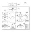
図1では12個のノズル10-j(j=1,2,3・・・12)が1列に並んだノズル列20を示した。記録媒体(不図示)は、図1の下から上に向かって搬送されるものとする。図1(a)は記録ヘッドの設置位置が正確である場合(設計上の理想状態)を示している。この場合、記録媒体の搬送方向(Y方向)に対して垂直方向(X方向)に複数個のノズル10-j(j=1,2,3・・・12)が等間隔で一列に配列された状態となる。 FIG. 1 shows a
これら同一直線上に並ぶ複数個のノズル10-j(j=1,2,3・・・12)から同時にインクを吐出させることにより、記録媒体上でX方向に一列にならぶ着弾ドット列を形成することが可能である。 By simultaneously ejecting ink from a plurality of nozzles 10-j (j = 1, 2, 3... 12) arranged on the same straight line, a landed dot row aligned in the X direction on the recording medium is formed. Is possible.
図1(b)は記録ヘッドの設置位置が設計上の理想的位置からずれて、XY面内で僅かに回転し、X方向に対してある角度θ(≠0)を有して斜めに設置された状態を示している。この場合、ノズル列20は記録媒体の搬送方向(Y方向)に対して、一定の角度φを持つ。角度φは、図1(b)から明らかなように、φ=90°−θ[deg]の関係を有する。 In FIG. 1B, the installation position of the recording head deviates from the ideal design position, rotates slightly in the XY plane, and is inclined with a certain angle θ (≠ 0) with respect to the X direction. It shows the state that was done. In this case, the
図1(b)のようにノズル列20がXY面内で傾き、X方向と非平行に、斜め方向に傾斜している場合には、記録媒体の搬送方向(Y方向)に対し、ノズル列20の傾きによって生じる記録媒体へのインク着弾位置のずれが生じてしまう。また、ノズル列20の傾きにより各ノズルのX方向位置がずれることによって、搬送方向に対して垂直方向(X方向)にインク着弾位置のずれが生じる。2次元のノズル配列においては、例えば、図20で説明したような状態となる。 As shown in FIG. 1B, when the
搬送方向(Y方向)に対するインク着弾位置のずれは、ノズルからインクを吐出するタイミング(記録タイミング)を補正して対応する。また、搬送方向と直交する用紙幅方向(X方向)に対するインク着弾位置のずれは、吐出させるノズルの選択で対応する。 The deviation of the ink landing position with respect to the transport direction (Y direction) is dealt with by correcting the timing (recording timing) of ejecting ink from the nozzles. Further, the deviation of the ink landing position with respect to the paper width direction (X direction) orthogonal to the transport direction is dealt with by selecting the nozzle to be ejected.
ノズル列20の傾きによって生じるX方向着弾位置ずれについては、特許文献1、2で述べられているようなノズル(記録素子)を選択する信号を生成して対応するため、その選択データの効率的な転送方法としては従来の技術を採用し得る。すなわち、駆動する記録素子を時分割選択し、所定の吐出タイミングで対応可能である。 The X direction landing position deviation caused by the inclination of the
その一方、搬送方向に対するインク着弾位置のずれ(Y方向着弾位置ずれ)に対しては、インクを吐出するタイミングをノズル毎に設定する必要があり、記録素子の駆動信号を時分割で送ることができないという問題がある。 On the other hand, with respect to the deviation of the ink landing position with respect to the transport direction (Y direction landing position deviation), it is necessary to set the ink ejection timing for each nozzle, and the recording element drive signal can be sent in a time-sharing manner. There is a problem that you can not.
記録ヘッドの各記録素子に外部からそれぞれの吐出タイミング信号、或いはタイミングデータを転送するには、転送量や端子数、回路数が膨大となり、また、転送時間も要する。 In order to transfer each ejection timing signal or timing data from the outside to each recording element of the recording head, the transfer amount, the number of terminals, and the number of circuits are enormous, and a transfer time is also required.
これらの課題を解決するために、本発明の実施形態による記録ヘッドは、次のような原理で各記録素子の駆動タイミング(ここでは、各ノズルからの吐出タイミングに相当)を補正するための補正データを定める。 In order to solve these problems, the recording head according to the embodiment of the present invention corrects the driving timing of each recording element (here, corresponding to the ejection timing from each nozzle) on the basis of the following principle. Define the data.
<補正の原理>
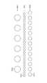
図2は、記録ヘッド(又は長尺ヘッドを構成するヘッドモジュール)の設置位置ずれにより傾斜したノズル列の各ノズルから同時に吐出を行った際の記録媒体上における着弾位置を模式的に示した図である。図2の破線円で示した位置は、設置位置ずれのない本来のノズル列によって打滴される理想的な着弾位置を示している。ノズル列が斜めに傾いていると、図2の実線円で示したように、各ノズルの配置位置に対応した着弾位置にドットが形成される。<Principle of correction>
FIG. 2 is a diagram schematically showing the landing position on the recording medium when discharging is simultaneously performed from each nozzle of the nozzle row inclined due to the installation position deviation of the recording head (or the head module constituting the long head). It is. The position indicated by the broken-line circle in FIG. 2 indicates an ideal landing position at which droplets are ejected by the original nozzle row with no installation position deviation. When the nozzle row is inclined, dots are formed at the landing positions corresponding to the arrangement positions of the nozzles, as indicated by the solid circle in FIG.
このような斜めに並ぶノズル配置に起因する搬送方向の位置ずれを是正するために、本実施形態では、1列に配列された各ノズルに対応する記録素子を、その並び順に連続する所定個数でグループ分けする。図2に示した例では、各ノズルに対応する記録素子4つを1ブロックとした。すなわち、12個のノズルを4個ずつグループ分けし、3つのブロック(グループ)を形成したものとなっている。ノズル10-1〜10-4は第1ブロック、ノズル10-5〜10-8は第2ブロック、ノズル10-9〜10-12は第3ブロックに属する。 In this embodiment, in order to correct the positional deviation in the transport direction due to such an obliquely arranged nozzle arrangement, in the present embodiment, a predetermined number of recording elements corresponding to each nozzle arranged in one row are continuously arranged. Divide into groups. In the example shown in FIG. 2, four recording elements corresponding to each nozzle are made one block. That is, 12 nozzles are divided into groups of 4 to form 3 blocks (groups). The nozzles 10-1 to 10-4 belong to the first block, the nozzles 10-5 to 10-8 belong to the second block, and the nozzles 10-9 to 10-12 belong to the third block.
なお仮に、1列を256ノズルとした場合には、4ノズルを1ブロックとすると、64ブロック形成されることになる。1ノズル列内のノズル数、並びに、1ブロック内に含まれるノズル数については、本例に限定されず、適宜設計可能である。 If there are 256 nozzles in one row, 64 blocks are formed with 4 nozzles as 1 block. The number of nozzles in one nozzle row and the number of nozzles included in one block are not limited to this example, and can be appropriately designed.
記録ヘッドが本来の設置位置に対して斜めに取り付けられ、ノズル配列に「斜めずれ」が発生した場合、当該記録ヘッドのノズル配列は記録媒体の搬送方向(Y方向)に対し、一定の角度を有している。したがって、ノズル列内における隣接ブロック間の搬送方向の相対的な位置ずれ量は、どの隣接ブロック間についても同じ(等量の)位置ずれ量となる。また、各ブロック内における各ノズル間の相対的な位置ずれ量は、どのブロック内でも同じ位置ずれ量となる。よって、それぞれのブロック内における各ノズルの吐出タイミングの補正値は、ブロック間で共通に使用できる。図2を用いて更に詳細に説明する。記録媒体は図2の下から上に向かって搬送されるものとする。 When the recording head is mounted obliquely with respect to the original installation position and a “diagonal shift” occurs in the nozzle array, the nozzle array of the recording head has a certain angle with respect to the recording medium conveyance direction (Y direction). Have. Therefore, the relative displacement amount in the transport direction between adjacent blocks in the nozzle row is the same (equal amount) displacement amount between any adjacent blocks. Further, the relative positional deviation amount between the nozzles in each block is the same positional deviation amount in any block. Therefore, the correction value of the ejection timing of each nozzle in each block can be used in common between the blocks. This will be described in more detail with reference to FIG. It is assumed that the recording medium is conveyed from the bottom to the top in FIG.
図2における各実線円は記録ヘッドにおける各ノズルの位置に対応している。図2で図1(b)に倣って各ノズルの着弾位置をノズルの符号によって示した。このノズル列において、記録媒体の搬送方向(Y方向)に対して最上流に位置するノズル10-12(記録媒体の給入側に向かってノズル列の一番先端に位置するノズル(以下、「列内基準ノズル」という。)に対応した記録素子の駆動タイミングが、当該ノズル列の基準起動信号となる。同ノズル列内の各ノズルに対応した記録素子の吐出タイミングを補正するための補正値は、基準起動信号の信号タイミングからクロック(CLK)信号のカウント値で定義される。 Each solid circle in FIG. 2 corresponds to the position of each nozzle in the recording head. In FIG. 2, the landing positions of the nozzles are indicated by the reference numerals of the nozzles, following FIG. 1 (b). In this nozzle row, the nozzle 10-12 located at the uppermost stream with respect to the conveyance direction (Y direction) of the recording medium (nozzle located at the extreme end of the nozzle row toward the recording medium feeding side (hereinafter, “ The drive timing of the printing element corresponding to “in-row reference nozzle”) becomes the reference activation signal of the nozzle row.A correction value for correcting the ejection timing of the printing element corresponding to each nozzle in the nozzle row. Is defined by the count value of the clock (CLK) signal from the signal timing of the reference activation signal.
列内基準ノズル10-12の吐出位置(Y方向の位置)を基準ラインSLとすると、当該ノズル列内で搬送方向の最下流に位置するノズル10-1の位置ずれ量が最大となる。 If the ejection position (Y-direction position) of the in-row reference nozzle 10-12 is defined as the reference line SL, the displacement amount of the nozzle 10-1 located at the most downstream side in the transport direction in the nozzle row is maximized.
各ノズルの吐出タイミングを補正する補正値は、ブロック別の補正値であるノズルブロック補正カウント値LBr(r=1,2,3)と、ブロック内の個別ノズルの補正値である個別ノズル補正カウント値L1s(s=0,1,2,3)との結合によって表される。「r」は注目するノズルが属するブロックを区別する番号、「s」はブロック内における注目ノズルの相対的な位置を特定する番号を意味している。つまり、ノズル列内における各ノズルの位置は、rとsによって一意に特定される。ブロック内のノズル個数をn(図2の場合n=4)とすると、ノズル番号j=n×(r−1)+(s+1)で表される。ただし、sは0≦s≦n−1を満たす整数である。 The correction values for correcting the ejection timing of each nozzle are the nozzle block correction count value LBr (r = 1, 2, 3), which is a correction value for each block, and the individual nozzle correction count, which is the correction value for individual nozzles in the block. It is represented by a combination with the value L1s (s = 0, 1, 2, 3). “R” is a number for identifying the block to which the target nozzle belongs, and “s” is a number for specifying the relative position of the target nozzle in the block. That is, the position of each nozzle in the nozzle row is uniquely specified by r and s. If the number of nozzles in the block is n (n = 4 in FIG. 2), the nozzle number is represented by j = n × (r−1) + (s + 1). However, s is an integer satisfying 0 ≦ s ≦ n−1.
<<ノズルブロック補正カウント値について>>
図2において、搬送方向の最下流に位置するノズル10-1が含まれる第1ブロック(r=1)は基準ラインに対してY方向に相対的な位置ずれ量ΔB1を有する。第2ブロック(r=2)は基準ラインに対してY方向に相対的な位置ずれ量ΔB2を有する。各ブロックのY方向位置は、そのブロック内で搬送方向の最上流に位置するノズル(以下、「ブロック内基準ノズル」という。)の位置とした。すなわち、第1ブロックのブロック内基準ノズルはノズル10-4であり、第2ブロックのブロック内基準ノズルは10-8、第3ブロック(r=3)のブロック内基準ノズルはノズル10-12である。<< Nozzle block correction count value >>
In FIG. 2, the first block (r = 1) including the nozzle 10-1 located on the most downstream side in the transport direction has a positional deviation amount ΔB1 relative to the reference line in the Y direction. The second block (r = 2) has a positional deviation amount ΔB2 relative to the reference line in the Y direction. The position in the Y direction of each block was set to the position of the nozzle (hereinafter referred to as “in-block reference nozzle”) located in the uppermost stream in the transport direction within the block. That is, the intra-block reference nozzle of the first block is the nozzle 10-4, the intra-block reference nozzle of the second block is 10-8, and the intra-block reference nozzle of the third block (r = 3) is the nozzle 10-12. is there.
隣接する第1ブロックと第2ブロックの間のY方向に対する相対的な位置ずれ量はΔB1-ΔB2である。第2ブロックと第3ブロックの間のY方向に対する相対的な位置ずれ量はΔB2である。これら隣接ブロック間の位置ずれ量は等しく、ΔB1=2×ΔB2の関係を満たす。 The relative positional shift amount with respect to the Y direction between the adjacent first block and second block is ΔB1-ΔB2. The relative positional deviation amount with respect to the Y direction between the second block and the third block is ΔB2. The positional deviation amounts between these adjacent blocks are equal and satisfy the relationship ΔB1 = 2 × ΔB2.
ブロックの数が増えた場合も同様であり、M個のブロックが形成された場合、搬送方向の最上流に位置する列内基準ノズルが属するM番目のブロックのY方向位置を基準ラインとし、隣接ブロック間のY方向に対する相対的な位置ずれ量をΔBとすれば、第J番目のブロックの基準ラインに対するY方向の相対的な位置ずれ量ΔBJは、ΔBJ=(M−J)×ΔBで表される(ただし、Jは1≦J≦Mを満たす整数)。なお、最上流の列内基準ノズルの位置と基準ラインの位置と一致させない場合には、基準ラインの位置と列内基準ノズルの位置とのY方向相対位置ずれ量ΔCが定数項として加わり、ΔBJ=(M−J)×ΔB+ΔCと表される。 The same applies when the number of blocks increases. When M blocks are formed, the Y-direction position of the M-th block to which the in-row reference nozzle located at the uppermost stream in the transport direction belongs is used as a reference line, If the relative positional deviation amount between the blocks in the Y direction is ΔB, the relative positional deviation amount ΔBJ in the Y direction with respect to the reference line of the J-th block is expressed by ΔBJ = (M−J) × ΔB. (Where J is an integer satisfying 1 ≦ J ≦ M). If the position of the reference nozzle in the uppermost row does not coincide with the position of the reference line, the relative displacement amount ΔC in the Y direction between the position of the reference line and the position of the reference nozzle in the row is added as a constant term, and ΔBJ = (M−J) × ΔB + ΔC.
搬送方向に対する物理的な位置ずれ量に対し、これを補正するための吐出タイミングの補正値は、位置ずれ量を記録媒体の搬送速度Vで除算して得られる時間差となる。こうして、ブロック別の吐出タイミングの補正値を表すカウント値(ブロック別補正値)が定められる。 The correction value of the ejection timing for correcting the physical positional deviation amount with respect to the conveyance direction is a time difference obtained by dividing the positional deviation amount by the conveyance speed V of the recording medium. In this way, a count value (block-specific correction value) representing the correction value of the ejection timing for each block is determined.
<<個別ノズル補正カウント値について>>
1つのブロック内(例えば、第1ブロック)に注目すると、ブロック内における個々のノズルは、ブロック内基準ノズルとの間で搬送方向に対し相対的な位置ずれ量ΔL1sを有する。例えば、第1ブロックに注目すると、当該ブロック内で最も位置ずれ量の大きいノズル10-1は、ブロック内基準ノズル10-4との間でY方向に相対的な位置ずれ量ΔL10を有する。ノズル10-2は、ブロック内基準ノズル10-4との間でY方向に相対的な位置ずれ量ΔL11を有する。ノズル10-3は、ブロック内基準ノズル10-4との間でY方向に相対的な位置ずれ量ΔL12を有する。<< Individual nozzle correction count value >>
Focusing on one block (for example, the first block), each nozzle in the block has a positional deviation amount ΔL1s relative to the reference nozzle in the block relative to the transport direction. For example, paying attention to the first block, the nozzle 10-1 having the largest positional deviation amount in the block has a positional deviation amount ΔL10 relative to the reference nozzle 10-4 in the block in the Y direction. The nozzle 10-2 has a relative displacement ΔL11 in the Y direction with respect to the in-block reference nozzle 10-4. The nozzle 10-3 has a relative positional deviation amount ΔL12 in the Y direction with respect to the in-block reference nozzle 10-4.
同一ブロック内で隣接するノズル間のY方向に対する相対的な位置ずれ量は等しい。この隣接ノズル間のY方向に対する相対的な位置ずれ量をΔDとすれば、ΔL10=3×ΔD、ΔL11=2×ΔD、ΔL12=ΔDと表すことができる。1ブロック内におけるs番のノズルのブロック内基準ノズルに対するY方向の相対的な位置ずれ量ΔL1s=(k−s−1)×ΔDである。 The relative positional deviation amount with respect to the Y direction between adjacent nozzles in the same block is equal. If the relative displacement between the adjacent nozzles in the Y direction is ΔD, it can be expressed as ΔL10 = 3 × ΔD, ΔL11 = 2 × ΔD, and ΔL12 = ΔD. The relative displacement amount ΔL1s = (k−s−1) × ΔD in the Y direction with respect to the reference nozzle in the block of the s-th nozzle in one block.
ブロック内に属する各記録素子の相対的位置関係は、各ブロックにおいて共通であり、同一ノズル列内の全てのブロックについて共通の関係が成り立つ。したがって、第1ブロック、第2ブロック及びそれ以降に続く他のブロックも同様に、各ブロック内の個々の記録素子に対する吐出タイミングを補正する値(個別ノズル補正カウント値)は、同一ノズル列内の全てのブロックについて共通となる。 The relative positional relationship of the printing elements belonging to the block is common to the blocks, and a common relationship is established for all the blocks in the same nozzle row. Accordingly, the values (individual nozzle correction count values) for correcting the ejection timing for the individual printing elements in each block are also the same in the first block, the second block, and the other blocks following the first block. It is common to all blocks.
<吐出タイミングの補正量の説明>
図3は、同一ノズル列内に属する各ノズルの吐出タイミングを補正するときの補正量の概念図である。図示のように、各ノズルの吐出タイミングは、基準起動信号のタイミングを基準にして、個別カウンタ回路のカウント値(L1s)と、ブロックカウンタ回路のカウント値(LBr)とを加算した値によって補正される。<Explanation of ejection timing correction amount>
FIG. 3 is a conceptual diagram of the correction amount when correcting the ejection timing of each nozzle belonging to the same nozzle row. As shown in the figure, the discharge timing of each nozzle is corrected by the value obtained by adding the count value (L1s) of the individual counter circuit and the count value (LBr) of the block counter circuit, based on the timing of the reference activation signal. The
個別カウンタ回路には、ブロック内のノズル位置に応じた個別カウント値L10、L11、L12、L13が設定される。ブロックカウンタ回路には、ブロック単位でブロックカウント値LB1、LB2、LB3が設定される。つまり、同じブロック内の記録素子に対しては、同じブロックカウント値が適用される。ブロック内の個別カウント値(L10,L11,L12,L13)は、これらを1組として、全てのブロックに共通に適用される。 In the individual counter circuit, individual count values L10, L11, L12, and L13 corresponding to the nozzle positions in the block are set. In the block counter circuit, block count values LB1, LB2, and LB3 are set in units of blocks. That is, the same block count value is applied to printing elements in the same block. The individual count values (L10, L11, L12, L13) in a block are applied in common to all the blocks as a set.
なお、記録ヘッドにおけるノズル列の傾き角度に応じて、グループ分けの際の記録素子数を適応的に変更してもよい。 Note that the number of printing elements in the grouping may be adaptively changed according to the inclination angle of the nozzle row in the printing head.
<記録ヘッドの具体的な構成例>
図4は、本発明の実施形態に係る記録ヘッドの構成図である。本実施形態の記録ヘッド40は、シフトレジスタ回路42、デコーダ回路44、ラッチ回路46、個別カウンタ回路48、ブロックカウンタ回路50、アンプ52、スイッチ素子54、記録素子56を含んで構成される。ここで示した記録素子56には、インク吐出口(ノズル)からインクを吐出するための吐出エネルギーを発生する吐出エネルギー発生素子(発熱抵抗素子、圧電素子、静電アクチュエータなど)が含まれる。<Specific configuration example of recording head>
FIG. 4 is a configuration diagram of the recording head according to the embodiment of the present invention. The
また、記録ヘッド40は、外部からシリアルデータを受け入れる端子60(「シリアルデータ受信部」に相当)と、その信号線61、クロック信号を受け入れる端子63とその信号線64、吐出基準信号(「基準起動信号」に相当)を受け入れる端子66とその信号線67を有する。その他、カウンタ回路のリセット信号(RST)、記録を行う記録素子56を選択するためのセレクト信号(SEL)を受け入れる端子とその信号線などを備えている。シフトレジスタ回路42、デコーダ回路44及びラッチ回路46の組み合わせによってデータ分配回路70が構成される。 The
本例の記録ヘッド40は、記録媒体の搬送方向に対し垂直方向に同列に(直線上に)配列されたノズルに対応した記録素子56を、所定の個数(n個)でグループ分けし、グループ単位で位置補正を行うグループ別の吐出タイミング補正値(ブロック別補正値に相当)をカウントするブロックカウンタ回路50と、同グループ内に属する各記録素子56間の相対的な位置補正を行う個別の吐出タイミング補正値(個別補正値に相当)をカウントする個別カウンタ回路48と、を備える。記録素子56のグループ分けは、X方向に一定間隔で並んだノズルの並び順に、連続する所定の個数(ただし、個数nは2以上の整数)のノズルを1つのグループ(ブロック)とする。ブロックカウンタ回路50には、ブロック単位でカウント値が設定される。図中破線の矩形によってブロックのまとまりを示した。 The
個別カウンタ回路48には、1ブロック内における各ノズルの相対的な位置に対応した個別のカウント値が設定される。各カウンタ回路48,50のカウント値は記録ヘッド40の外部よりシリアルデータで受信し、データ分配回路70にてデータを展開して、各ブロックカウンタ回路50と各個別カウンタ回路48へ転送する。これにより、各カウンタ回路48,50にそれぞれのカウント値がセットされる。図4では、各個別カウンタ回路48にカウント値(L10、L11、・・・L1n)がセットされ、各ブロック内の各ブロックカウンタ回路50に対して、ブロック単位で共通のカウント値(LB1、LB2、・・・LBn)がセットされる。 In the
各個別カウンタ回路48は、基準起動信号の入力によりカウントが開始され、セットされたカウント値のカウント終了時に個別補正タイミング信号(C10、C11、・・・C1n)を出力する。各ブロックカウンタ回路50は、それぞれ対応する個別カウンタ回路48からの個別補正タイミング信号の入力によりカウントが開始され、セットされたカウント値のカウント終了時に信号(個別補正値とブロック補正値とが組み合わされた補正タイミング信号)を出力する。この出力信号が記録素子56の駆動タイミングを規定する信号(補正タイミング信号)となり、記録素子56に対応したアンプ52に入力される。 Each
つまり、基準起動信号を基準にして、個別カウンタ回路48のカウント値とブロックカウンタ回路50のカウント値とを合算したカウント値(補正値)により、各記録素子56の補正タイミング信号が生成される。この補正タイミング信号に従って各記録素子56が駆動され、インク滴の吐出(ドットの記録)が行われる。 In other words, the correction timing signal of each
図4の例では、各記録素子56に対応して記録素子56と同数のブロックカウンタ回路50を備えるとともに、1ブロック内のノズル数(記録素子56の個数)と同数の個別カウンタ回路48を備え、個別カウンタ回路48の出力信号(C10、C11、・・・C1n)を、各ブロック内のブロックカウンタ回路50に供給する構成を示した。 In the example of FIG. 4, the same number of
ただし、本発明の実施に際しては、図4に例示した「個別カウンタ回路48」→「ブロックカウンタ回路50」の順にカウント値をカウントする形態に限らず、カウント順序を逆にしてもよい。すなわち、「ブロックカウンタ回路」→「個別カウンタ回路」の順でカウント値をカウントしてもよい。この場合、先にカウントするブロックカウンタ回路に対して基準起動信号が入力され、ブロックカウンタ回路のカウントが開始される。ブロックカウンタ回路にセットされたカウント値のカウント終了時にブロックカウンタ回路から信号が出力され、この信号を受けて個別カウンタ回路のカウントが開始される。かかる形態は、図4に示した個別カウンタ回路48とブロックカウンタ回路50の構成に代えて、グループ分けされたブロック数と同数のブロックカウンタ回路と、記録素子56と同数の個別カウンタ回路と、によって構成することができる。 However, when implementing the present invention, the count order is not limited to the form of counting in the order of “
また、基準起動信号は、少なくとも先にカウントを開始するカウンタ回路に入力すれば足りるが、後段のカウンタ回路に対してもタイミング調整用などのために基準起動信号を与える構成を採用することができる。いずれの場合も、最終的に基準起動信号を基準にして補正したタイミング信号がえられればよい。 Further, it is sufficient that the reference activation signal is input to at least the counter circuit that starts counting first. However, a configuration in which the reference activation signal is given to the subsequent counter circuit for timing adjustment or the like can also be adopted. . In either case, it is only necessary to finally obtain a timing signal corrected with reference to the reference activation signal.
複数のノズル列(記録素子列)が平行に配置された記録ヘッドにおいては、記録媒体の搬送方向に対して、第1列目となる記録素子列(最上流に位置するノズル列)の基準起動信号を、他の列にも共通に用いることができる。 In a recording head in which a plurality of nozzle arrays (recording element arrays) are arranged in parallel, the reference activation of the first recording element array (the nozzle array positioned at the most upstream position) in the conveyance direction of the recording medium The signal can be used in common for other columns.
図5は、個別カウンタ回路48及びブロックカウンタ回路50にそれぞれカウント値をロード(セット)するときのデータの流れを模式的に示した図である。ヘッド外部(例えば、ヘッド制御回路を搭載した駆動基板など)から入力されたシリアルデータは、データ分配回路70によって展開され、個別カウンタ回路のカウント値(L10〜L13)及びブロックカウンタ回路のカウント値(LB1〜LBn)がそれぞれのカウンタ回路にロード(セット)される。 FIG. 5 is a diagram schematically showing the flow of data when the count value is loaded (set) into the
<同じ配列密度のノズル列を複数列備える記録ヘッドの場合>
同じ配列密度のノズル列を複数列備え、これらが平行に配置されている記録ヘッドの場合、各列に対応したブロックカウンタ回路及び個別カウンタ回路に設定するブロック別補正値及び個別補正値のデータは、同じ転送データを共用することができる。<In the case of a recording head including a plurality of nozzle rows having the same arrangement density>
In the case of a print head that includes a plurality of nozzle rows having the same arrangement density and these are arranged in parallel, the block-specific correction value data and the individual correction value data set in the block counter circuit and the individual counter circuit corresponding to each row are The same transfer data can be shared.
<異なる配列密度のノズル列を複数列備える記録ヘッドの構成について>
次に、複数のノズル列を有する記録ヘッドにおいて、列によってノズルサイズと、横に隣接するノズル間隔が異なる場合(異なる配列密度のノズル列を複数列有する場合)について説明する。<Regarding the configuration of a recording head including a plurality of nozzle rows having different arrangement densities>
Next, in a recording head having a plurality of nozzle rows, a case where the nozzle size and the interval between adjacent nozzles are different depending on the row (when there are a plurality of nozzle rows having different arrangement densities) will be described.
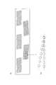
図6に示すように、ノズルサイズと隣接ノズル間隔がそれぞれ列間で互いに異なる2列のノズル列を例に説明する。図6において上段のノズル列を第1列、下段のノズル列を第2列とする。第1列のノズルサイズは第2列のノズルサイズよりも大きく、第1列の隣接ノズル間隔(ノズルピッチ)は、第2列の隣接ノズル間隔よりも大きい。列内における隣接ノズル間隔が小さいほど、配列密度は高い。 As shown in FIG. 6, description will be given by taking as an example two nozzle rows in which the nozzle size and the interval between adjacent nozzles are different from each other between rows. In FIG. 6, the upper nozzle row is the first row, and the lower nozzle row is the second row. The nozzle size in the first row is larger than the nozzle size in the second row, and the adjacent nozzle interval (nozzle pitch) in the first row is larger than the adjacent nozzle interval in the second row. The smaller the spacing between adjacent nozzles in a row, the higher the array density.
図6では、第1列のノズル列と第2列のノズル列をそれぞれ同じ記録素子数(ここでは4つ)でグループ分けした様子が示されている。第1列のノズル列に比べて、小ノズルで、且つ配列密度の高い第2列のノズル列について、第1列と同じ記録素子数でグループ分けすると、単純に、ブロックカウンタ回路の数がノズル密度の割合で増加することになる。 また、第2列に対応する個別カウンタ回路のカウント値は、第1列とは別に改めてデータ転送することになる。なお、ノズルサイズと、横に隣接するノズル間隔が同じノズル列に対しては、カウント値を共用できる。 FIG. 6 shows a state in which the first row of nozzles and the second row of nozzles are grouped by the same number of printing elements (here, four). When the second nozzle row, which has smaller nozzles and higher arrangement density than the first row, is grouped by the same number of printing elements as the first row, the number of block counter circuits is simply the number of nozzles. It will increase at a density rate. In addition, the count value of the individual counter circuit corresponding to the second column is transferred again separately from the first column. A count value can be shared for nozzle rows having the same nozzle size and the interval between adjacent nozzles.
<異なる配列密度のノズル列を複数備える記録ヘッドの他の構成例1>
記録素子のグループ分けの方法に関する他の形態例を説明する。図7に示すように、平行に配置された複数のノズル列81、82のうち相対的に配列密度が低い列(ここでは符号81で示した第1列)について所定個数(4個を例示)でグループ分けし、そのグループ内における両端のノズルの位置に合わせて、配列密度が相対的に高い列(ここでは符号82で示した第2列)のノズルをグループ分けする。つまり、第1列をグループ分けして得られる各ブロックのノズル範囲BPに対応した第2列におけるノズル領域を更に細かく等分割することにより、第2列のグループ分けが行われる。図7では、第1列の各ブロックのノズル範囲BPに対応した第2列のノズル領域(8個のノズルが並んだノズル範囲)を、2等分して4個ずつのグループ(ブロック)に分けている。<Another configuration example 1 of a recording head including a plurality of nozzle rows having different arrangement densities>
Another embodiment relating to a method of grouping recording elements will be described. As shown in FIG. 7, among a plurality of nozzle rows 81 and 82 arranged in parallel, a predetermined number (four examples) of rows having a relatively low arrangement density (here, the first row indicated by reference numeral 81). The nozzles in a row having a relatively high arrangement density (here, the second row indicated by reference numeral 82) are grouped in accordance with the positions of the nozzles at both ends in the group. That is, the grouping of the second row is performed by further finely dividing the nozzle region in the second row corresponding to the nozzle range BP of each block obtained by grouping the first row. In FIG. 7, the second row of nozzle areas (nozzle range in which eight nozzles are arranged) corresponding to the nozzle range BP of each block of the first row is divided into two equal groups (blocks). It is divided.
このようなグループ分けにより、第1列における各ブロックの位置と、第2列における各ブロックの位置との対応関係(ブロック単位の位置関係)が維持される。 By such grouping, the correspondence relationship (positional relationship in units of blocks) between the position of each block in the first column and the position of each block in the second column is maintained.
なお、図7では、第2列の配列密度が第1列の配列密度の2倍であるため、第2列のグループ分けに際して、第1列の1ブロック範囲を2等分したが、配列密度の割合に応じて分割数(ブロック数)を変えることができる。また、第1列の各ブロック内に含まれるノズル数(記録素子数)と、第2列の各ブロック内に含まれるノズル数(記録素子数)は、等しいことが好ましいが、必ずしも一致している必要はない。 In FIG. 7, since the arrangement density of the second column is twice the arrangement density of the first column, one block range of the first column is divided into two equal parts when grouping the second column. The number of divisions (number of blocks) can be changed in accordance with the ratio. In addition, the number of nozzles (number of printing elements) included in each block of the first row and the number of nozzles (number of printing elements) included in each block of the second row are preferably equal, but they are not necessarily the same. There is no need to be.
このような構成を採用することにより、各列のブロックカウンタ回路のカウント値を第1列と第2列とで共用することができ、データ転送量を削減できる。 By adopting such a configuration, the count value of the block counter circuit of each column can be shared by the first column and the second column, and the data transfer amount can be reduced.
<異なる配列密度のノズル列を複数備える記録ヘッドの他の構成例2>
図8は、他の形態例の説明図である。配列密度が異なる複数のノズル列が互いに平行に配置されている場合、ノズル列の傾斜による搬送方向の着弾位置ずれ量は、ノズルの位置に応じた比例関係で表される。吐出タイミングの補正量は、クロック信号のカウント値で表されるため、クロック周期×カウント値によって補正時間が得られる。よって、カウント値を共通にして、クロック周期(周波数の逆数)を変更しても補正量を調整できる。<Other configuration example 2 of a recording head including a plurality of nozzle rows having different arrangement densities>
FIG. 8 is an explanatory diagram of another embodiment. When a plurality of nozzle rows having different arrangement densities are arranged in parallel to each other, the landing position deviation amount in the transport direction due to the inclination of the nozzle rows is represented by a proportional relationship according to the position of the nozzle. Since the ejection timing correction amount is represented by the count value of the clock signal, the correction time is obtained by the clock cycle × count value. Therefore, the correction amount can be adjusted even if the count value is shared and the clock cycle (reciprocal of the frequency) is changed.
図8に示すように、記録ヘッド内で最も配列密度の高いノズル列(ここでは符号84で示した第2列)の個別カウンタ回路及びブロックカウンタ回路に与えるクロック信号の周波数を基準とし、他のノズル列(ここでは符号85で示した第1列)の個別カウンタ回路及びブロックカウンタ回路に与えるクロック信号の周波数を、両列の配列密度の割合に応じて変更する。図8の第1列の配列密度は、第2列の配列密度の1/2であることから、第1列のクロック周波数は第2列のクロック周波数の1/2倍とする。一般に、配列密度がk倍であればクロック周波数をk倍とする(ただし、kは0よりも大きい実数)。このように、配列密度の割合に応じて該当ノズル列のカウンタ回路におけるクロック周波数を変えることで、配列密度の高いノズル列を全ノズル列の共通のカウント値としてデータ転送するだけでよい。 As shown in FIG. 8, the frequency of the clock signal applied to the individual counter circuit and the block counter circuit of the nozzle row (here, the second row denoted by reference numeral 84) having the highest arrangement density in the recording head is used as a reference. The frequency of the clock signal applied to the individual counter circuit and the block counter circuit of the nozzle row (here, the first row indicated by reference numeral 85) is changed according to the ratio of the arrangement density of both rows. Since the arrangement density of the first column in FIG. 8 is ½ of the arrangement density of the second column, the clock frequency of the first column is set to ½ times the clock frequency of the second column. In general, if the arrangement density is k times, the clock frequency is k times (where k is a real number greater than 0). As described above, by changing the clock frequency in the counter circuit of the corresponding nozzle row in accordance with the ratio of the arrangement density, it is only necessary to transfer data as a common count value for all the nozzle rows for the nozzle row having a high arrangement density.
なお、この場合、各ノズル列の基準起動信号は、そのノズル列の調整用として個別に用意してもよい。また、各ノズル列のカウンタ回路に与えるクロック信号は、ヘッド外部から受信してもよいし、記録ヘッド内部にクロック発生回路を設け、ヘッド外部からの入力する信号に同期させて記録ヘッド内で各種のクロック信号を生成してもよい。 In this case, the reference activation signal for each nozzle row may be prepared individually for adjustment of the nozzle row. The clock signal to be supplied to the counter circuit of each nozzle row may be received from the outside of the head, or a clock generation circuit is provided inside the recording head, and various kinds of signals are generated within the recording head in synchronization with the signal input from the outside of the head. The clock signal may be generated.
<データ分配回路の説明>
次に、データ分配回路について説明する。図9はデータ分配回路70の構成図である。各ブロックカウンタ回路と各個別カウンタ回路の補正タイミング信号を生成するカウント値のデータはシリアルデータの形式で予め記録ヘッドに送られる。このシリアルデータは、記録装置の記録ヘッド初期化時に転送されてくる。<Description of data distribution circuit>
Next, the data distribution circuit will be described. FIG. 9 is a configuration diagram of the
データ分配回路70は、各カウンタ回路のカウント値をシリアルデータで受信し、このシリアルデータ内のデータアドレス値によって各カウンタ回路へデータを展開する。データ分配回路70は、シリアルデータからシフトレジスタ回路42を介して各ノズルのカウントデータを展開するデコーダ回路44と、そのデコーダ回路44によってカウントデータを保持するラッチ回路46にて構成される。なお、デコーダ回路44は、ストローブ信号(STB)によってデコード動作の可能/不可能が制御される。 The
図10は、データ分配回路70で受信されるノズル1列分のシリアルデータの例である。ここでは、1列のノズル列が256ノズルで構成されているものとし、1ブロックが4ノズルで構成され、合計64ブロックにグループ分けされている例を示した。図示のように、シリアルデータには、1ブロック内における相対的なノズルの位置を特定するためのブロック内ノズルアドレスと、そのアドレスに対応した個別カウント値のデータのペア(組)が4ノズル分(ブロック内ノズル数分)含まれ、更に、列内における各ブロックの相対的な位置を特定するためのブロックアドレスと、そのアドレスに対応したブロックカウント値のデータのペア(組)が64ブロック分(列内ブロック数分)含まれている。 FIG. 10 is an example of serial data for one row of nozzles received by the
ブロック内の個別カウント値は64ブロックの各ブロックに対して共通に利用できるため、1列のノズル列あたり4ノズル分を1組とした1セットのみを転送すれば足りる。 Since the individual count value in the block can be used in common for each of the 64 blocks, it is sufficient to transfer only one set of four nozzles per nozzle row.
このような転送方法を採用することにより、256ノズルの各吐出タイミングの補正に必要なデータとして、64個のブロック補正値のカウント値と4個の個別補正値のカウント値のデータを転送すればよく、ノズル毎の補正値のデータを個々に転送する場合と比較して、データ転送量を削減することができる。 By adopting such a transfer method, if data of 64 block correction value count values and 4 individual correction value count values is transferred as data necessary for correction of each ejection timing of 256 nozzles. In many cases, the data transfer amount can be reduced as compared with the case of individually transferring correction value data for each nozzle.
シリアルデータは、データ転送量を少なくするために補正に必要なノズルデータ、或いは補正値修正(例えば、補正値が適切でなかった場合に一部修正など)の必要なノズルデータのみを転送してもよい。 For serial data, transfer only the nozzle data necessary for correction to reduce the data transfer amount, or the nozzle data necessary for correction value correction (for example, partial correction when the correction value is not appropriate). Also good.
また、異なるノズル配列密度を有する複数のノズル列を備える記録ヘッドの同じ配列密度のノズル列に対し、共通にタイミング補正を行う場合は、データ分配回路70に転送されるシリアルデータにおいて、配列密度に応じたコードデータをアドレスの上位ビットに付加し、そのコードデータに従ってデータ分配回路70にてデータ分配してもよい。図11にその例を示す。 In addition, in the case where timing correction is performed in common for nozzle rows having the same arrangement density of recording heads having a plurality of nozzle rows having different nozzle arrangement densities, the arrangement density is reduced in the serial data transferred to the
図11に示すように、アドレスバイトの上位ビットに配列密度を示すコードデータが付与される。ここでは、配列密度の違いに対応して高密度(ノズルサイズ小)、中密度(ノズルサイズ中)、低密度(ノズルサイズ大)の3種類のノズル列を備えた記録ヘッドにおいて、各配列密度に対応したノズル列を指定するためのコード「01」、「10」、「11」と、全ノズル列に対して適用する場合のコード「00」の4種類のコードデータが定義される例を示した。デコーダ回路によって、コードデータが読み取られ、該当するノズル列のカウンタ回路にカウント値が転送される。 As shown in FIG. 11, code data indicating the array density is given to the upper bits of the address byte. Here, in a recording head having three types of nozzle rows corresponding to the difference in arrangement density, high density (small nozzle size), medium density (medium nozzle size), and low density (large nozzle size), each arrangement density An example in which four types of code data are defined: code “01”, “10”, “11” for designating the nozzle row corresponding to the code “00” and code “00” when applied to all nozzle rows Indicated. The code data is read by the decoder circuit, and the count value is transferred to the counter circuit of the corresponding nozzle row.
また、ノズル配列密度に関係なくノズル列毎にタイミング補正を行う場合はシリアルデータのヘッダーにノズル列を識別するコードデータを付加してもよい。このコードデータはカウントデータと同様の方法で展開し、該当ノズル列のカウントデータ出力をON/OFFする。 When timing correction is performed for each nozzle row regardless of the nozzle arrangement density, code data for identifying the nozzle row may be added to the serial data header. This code data is developed in the same manner as the count data, and the count data output of the corresponding nozzle row is turned ON / OFF.
<インクジェット記録装置の構成>
図12は、本実施形態による記録ヘッド40とその制御装置90とを組み合わせたインクジェット記録装置95(「液体吐出装置」に相当)の構成を示したブロック図である。図12において、図4で説明した構成と同一又は対応する要素には同一の符号を付し、その説明は省略する。<Configuration of inkjet recording apparatus>
FIG. 12 is a block diagram showing a configuration of an ink jet recording apparatus 95 (corresponding to “liquid ejecting apparatus”) in which the
制御装置90は、記録ヘッド40の記録動作を制御する制御回路を含む装置であり、記録ヘッド40に対し、吐出タイミングの補正に必要な補正値のシリアルデータ、クロック信号、基準起動信号を提供するとともに、記録データ、ノズル選択信号など、各種の信号を提供する。なお、印字に関わる記録素子56の選択、すなわち画像データによるスイッチ信号がスイッチ素子54に加わる。 The
図12では記録ヘッド40内にクロック生成回路65を具備した例を示したが、これを省略して、制御装置90内に備えたクロック発生回路の信号をカウンタ回路(48,50)に供給してもよい。 FIG. 12 shows an example in which the
本発明の実施形態によれば、その構成により、以下の作用効果を奏する。 According to the embodiment of the present invention, the following effects are achieved by the configuration.
(1)ヘッド内部の1列に配列された各ノズルからインクを吐出するタイミングを生成するカウンタ回路(48,50)を有し、そのカウントデータは所定のノズル数でグループ分けしたグループ単位の値(ブロック別補正値)と、各グループ共通でグループ内の個々のノズルに対応した値(個別補正値)をシリアルデータで転送する。このような構成により、補正データの転送量を削減することができる。 (1) It has a counter circuit (48, 50) that generates the timing for ejecting ink from each nozzle arranged in one row inside the head, and the count data is a group unit value divided into groups by a predetermined number of nozzles. (Block-specific correction value) and a value (individual correction value) corresponding to each nozzle in the group common to each group are transferred as serial data. With such a configuration, the transfer amount of correction data can be reduced.
(2)また、ブロック(グループ)単位で転送するカウント値(ブロック別補正値)は、ブロックの並び順でブロック毎に一定の率(割合)で増加させることができる。 (2) Further, the count value (block-specific correction value) transferred in units of blocks (groups) can be increased at a constant rate (ratio) for each block in the block arrangement order.
(3)同じノズル列内、或いはノズル列間でカウント値を共用できるため、データ展開する回路数を少なくできる。 (3) Since the count value can be shared within the same nozzle row or between nozzle rows, the number of circuits for data development can be reduced.
(4)異なる配列密度のノズル列を備える構成において、ノズル列に対応したカウントデータを転送する場合、適用するノズル列の配列密度に応じてグルーピングするノズル数を決定し、全ノズル列のブロックカウント値を共通化することも可能である。 (4) In a configuration including nozzle rows having different arrangement densities, when transferring count data corresponding to the nozzle rows, the number of nozzles to be grouped is determined according to the arrangement density of the nozzle rows to be applied, and the block count of all nozzle rows is determined. It is also possible to share values.
これにより、補正データの転送量を削減できる。また、データ展開する回路数を少なくできる。 Thereby, the transfer amount of correction data can be reduced. In addition, the number of circuits for data expansion can be reduced.
(5)シリアルデータは、補正の必要なノズルデータ、或いは、補正値修正の必要なノズルデータ(修正用のデータ)のみを転送し、補正不要なノズル、修正不要なノズルに関するデータの転送を省略することにより、補正或いは転送データ修正の時間を短くすることができる。 (5) For serial data, only nozzle data that needs correction or nozzle data that needs correction correction (correction data) is transferred, and transfer of data relating to nozzles that do not need correction and nozzles that do not need correction is omitted. By doing so, the time for correction or transfer data correction can be shortened.
(6)本発明の適用により、各記録素子の駆動タイミングを補正する吐出データを吐出周期内に効率よく転送することができる。 (6) By applying the present invention, it is possible to efficiently transfer ejection data for correcting the drive timing of each printing element within the ejection cycle.
<インクジェット記録装置の具体的な構成例>
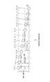
図13は、本発明の実施形態に係るインクジェット記録装置100の構成例を示す図である。インクジェット記録装置100は、主として、給紙部112、処理液付与部1214、描画部116、乾燥部118、定着部120、及び排紙部122を備えて構成される。このインクジェット記録装置100は、描画部116の圧胴(描画ドラム170)に保持された記録媒体124(便宜上「用紙」と呼ぶ場合がある。)にインクジェットヘッド(「記録ヘッド」に相当)172M,172K,172C,172Yから複数色のインクを打滴して所望のカラー画像を形成するオンデマンドドロップ方式の画像形成装置である。<Specific configuration example of inkjet recording apparatus>
FIG. 13 is a diagram illustrating a configuration example of the
(給紙部)
給紙部112には、枚葉紙である記録媒体124が積層されている。給紙部112の給紙トレイ150から記録媒体124が一枚ずつ処理液付与部114に給紙される。本例では、記録媒体124として、枚葉紙(カット紙)を用いるが、連続用紙(ロール紙)から必要なサイズに切断して給紙する構成も可能である。(Paper Feeder)
A
(処理液付与部)
処理液付与部114は、記録媒体124の記録面に処理液を付与する機構である。処理液は、描画部116で付与されるインク中の色材(本例では顔料)を凝集させる色材凝集剤を含んでおり、この処理液とインクとが接触することによって、インクは色材と溶媒との分離が促進される。(Processing liquid application part)
The processing
処理液付与部114は、給紙胴152、処理液ドラム154、及び処理液塗布装置156を備えている。処理液ドラム154は、その外周面に爪形状の保持手段(グリッパー)155を備え、この保持手段155の爪と処理液ドラム154の周面の間に記録媒体124を挟み込むことによって記録媒体124の先端を保持できるようになっている。処理液ドラム154は、その外周面に吸引孔を設けるとともに、吸引孔から吸引を行う吸引手段を接続してもよい。これにより記録媒体124を処理液ドラム154の周面に密着保持することができる。 The processing
処理液ドラム154の外側には、その周面に対向して処理液塗布装置156が設けられる。処理液塗布装置156は、処理液が貯留された処理液容器と、この処理液容器の処理液に一部が浸漬されたアニックスローラと、アニックスローラと処理液ドラム154上の記録媒体124に圧接されて計量後の処理液を記録媒体124に転移するゴムローラとで構成される。本実施形態では、ローラによる塗布方式を適用した構成を例示したが、これに限定されず、例えば、スプレー方式、インクジェット方式などの各種方式を適用することも可能である。 A processing
処理液付与部114で処理液が付与された記録媒体124は、処理液ドラム154から中間搬送部126を介して描画部116の描画ドラム170へ受け渡される。 The
(描画部)
描画部116は、描画ドラム170、用紙抑えローラ174、及びインクジェットヘッド172M,172K,172C,172Yを備えている。描画ドラム170は、処理液ドラム154と同様に、その外周面に爪形状の保持手段(グリッパー)171を備える。本例の描画ドラム170では、回転方向について180度の間隔で周面の2箇所にグリッパー171が設けられ、1回転で2枚の記録媒体124が搬送できるように構成されている。(Drawing part)
The
描画ドラム170の周面には、図示しない吸着穴が所定のパターンで多数形成されており、この吸着穴からエアが吸引されることにより、記録媒体124が描画ドラム170の周面に吸着保持される。なお、負圧吸引によって記録媒体124を吸引吸着する構成に限らず、例えば、静電吸着により、記録媒体124を吸着保持する構成とすることもできる。 A large number of suction holes (not shown) are formed in a predetermined pattern on the peripheral surface of the drawing drum 170, and the
インクジェットヘッド172M,172K,172C,172Yはそれぞれ、記録媒体124における画像形成領域の最大幅に対応する長さを有するフルライン型のインクジェット方式の記録ヘッドであり、そのインク吐出面には、画像形成領域の全幅にわたってインク吐出用のノズルが複数配列されたノズル列が形成されている。各インクジェットヘッド172M,172K,172C,172Yは、記録媒体124の搬送方向(描画ドラム170の回転方向)と直交する方向に延在するように設置される。 Each of the inkjet heads 172M, 172K, 172C, and 172Y is a full-line inkjet recording head having a length corresponding to the maximum width of the image forming area in the
描画ドラム170上に密着保持された記録媒体124の記録面に向かって各インクジェットヘッド172M,172K,172C,172Yから、対応する色インクの液滴が吐出されることにより、処理液付与部114で予め記録面に付与された処理液にインクが接触し、インク中に分散する色材(顔料)が凝集され、色材凝集体が形成される。これにより、記録媒体124上での色材流れなどが防止され、記録媒体124の記録面に画像が形成される。 The droplets of the corresponding color ink are ejected from the inkjet heads 172M, 172K, 172C, and 172Y toward the recording surface of the
描画ドラム170によって記録媒体124を一定の速度で搬送し、この搬送方向について、記録媒体124と各インクジェットヘッド172M,172K,172C,172Yを相対的に移動させる動作を1回行うだけで(即ち1回の副走査で)、記録媒体124の画像形成領域に画像を記録することができる。かかるフルライン型(ページワイド)ヘッドによるシングルパス方式の画像形成は、記録媒体の搬送方向(副走査方向)と直交する方向(主走査方向)に往復動作するシリアル(シャトル)型ヘッドによるマルチパス方式を適用する場合に比べて高速印字が可能であり、プリント生産性を向上させることができる。 The
なお、本例では、CMYKの標準色(4色)の構成を例示したが、インク色や色数の組み合わせについては本実施形態に限定されず、必要に応じて淡インク、濃インク、特別色インクを追加してもよい。例えば、ライトシアン、ライトマゼンタなどのライト系インクを吐出するインクジェットヘッドを追加する構成も可能であり、各色ヘッドの配置順序も特に限定はない。 In this example, the configuration of CMYK standard colors (four colors) is illustrated, but the combination of ink colors and the number of colors is not limited to this embodiment, and light ink, dark ink, and special colors are used as necessary. Ink may be added. For example, it is possible to add an inkjet head that discharges light-colored ink such as light cyan and light magenta, and the arrangement order of the color heads is not particularly limited.
描画部116で画像が形成された記録媒体124は、描画ドラム170から中間搬送部128を介して乾燥部118の乾燥ドラム176へ受け渡される。 The
(乾燥部)
乾燥部118は、色材凝集作用により分離された溶媒に含まれる水分を乾燥させる機構であり、乾燥ドラム176、及び溶媒乾燥装置178を備えている。乾燥ドラム176は、処理液ドラム154と同様に、その外周面に爪形状の保持手段(グリッパー)177を備える。溶媒乾燥装置178は、乾燥ドラム176の外周面に対向する位置に配置され、複数のハロゲンヒータ180と、各ハロゲンヒータ180の間にそれぞれ配置された温風噴出しノズル182とで構成される。乾燥部118で乾燥処理が行われた記録媒体124は、乾燥ドラム176から中間搬送部130を介して定着部120の定着ドラム184へ受け渡される。(Drying part)
The drying
(定着部)
定着部120は、定着ドラム184、ハロゲンヒータ186、定着ローラ188、及びインラインセンサ190を含んで構成される。定着ドラム184は、処理液ドラム154と同様に、その外周面に爪形状の保持手段(グリッパー)185を備える。(Fixing part)
The fixing
定着ドラム184の回転により、記録媒体124は記録面が外側を向くようにして搬送され、この記録面に対して、ハロゲンヒータ186による予備加熱と、定着ローラ188による定着処理と、インラインセンサ190による検査が行われる。 With the rotation of the fixing drum 184, the
定着ローラ188は、乾燥させたインクを加熱加圧することによってインク中の自己分散性ポリマー微粒子を溶着し、インクを被膜化させるためのローラ部材であり、記録媒体124を加熱加圧するように構成される。具体的には、定着ローラ188は、定着ドラム184に対して圧接するように配置されており、定着ドラム184との間でニップローラを構成するようになっている。これにより、記録媒体124は、定着ローラ188と定着ドラム184との間に挟まれ、所定のニップ圧(例えば、0.15MPa)でニップされ、定着処理が行われる。 The fixing
また、定着ローラ188は、熱伝導性の良いアルミなどの金属パイプ内にハロゲンランプを組み込んだ加熱ローラによって構成され、所定の温度(例えば60〜80℃)に制御される。この加熱ローラで記録媒体124を加熱することによって、インクに含まれるラテックスのTg温度(ガラス転移点温度)以上の熱エネルギーが付与され、ラテックス粒子が溶融される。これにより、記録媒体124の凹凸に押し込み定着が行われるとともに、画像表面の凹凸がレベリングされ、光沢性が得られる。 The fixing
一方、インラインセンサ190は、記録媒体124に形成された画像(不吐出検出用のテストパターンや濃度補正用のテストパターン、印刷画像なども含む)について、吐出不良チェックパターンや画像の濃度、画像の欠陥などを計測するための計測手段であり、CCDラインセンサなどが適用される。 On the other hand, the in-
なお、高沸点溶媒及びポリマー微粒子(熱可塑性樹脂粒子)を含んだインクに代えて、UV露光にて重合硬化可能なモノマー成分を含有していてもよい。この場合、インクジェット記録装置100は、ヒートローラによる熱圧定着部(定着ローラ188)の代わりに、記録媒体124上のインクにUV光を露光するUV露光部を備える。このように、UV硬化性樹脂などの活性光線硬化性樹脂を含んだインクを用いる場合には、加熱定着の定着ローラ188に代えて、UVランプや紫外線LD(レーザダイオード)アレイなど、活性光線を照射する手段が設けられる。 In addition, instead of the ink containing the high boiling point solvent and the polymer fine particles (thermoplastic resin particles), a monomer component that can be polymerized and cured by UV exposure may be contained. In this case, the
(排紙部)
定着部120に続いて排紙部122が設けられている。排紙部122は、排出トレイ192を備えており、この排出トレイ192と定着部120の定着ドラム184との間に、これらに対接するように渡し胴194、搬送ベルト196、張架ローラ198が設けられている。記録媒体124は、渡し胴194により搬送ベルト296に送られ、排出トレイ192に排出される。搬送ベルト196による用紙搬送機構の詳細は図示しないが、印刷後の記録媒体124は無端状の搬送ベルト196間に渡されたバー(不図示)のグリッパーによって用紙先端部が保持され、搬送ベルト196の回転によって排出トレイ192の上方に運ばれてくる。(Output section)
Subsequent to the fixing
また、図13には示されていないが、本例のインクジェット記録装置100には、上記構成の他、各インクジェットヘッド172M,172K,172C,172Yにインクを供給するインク貯蔵/装填部、処理液付与部114に対して処理液を供給する手段を備えるとともに、各インクジェットヘッド172M,172K,172C,172Yのクリーニング(ノズル面のワイピング、パージ、ノズル吸引、ノズル洗浄等)を行うヘッドメンテナンス部や、用紙搬送路上における記録媒体124の位置を検出する位置検出センサ、装置各部の温度を検出する温度センサなどを備えている。 Although not shown in FIG. 13, in addition to the above-described configuration, the ink
<インクジェットヘッドの構成例>
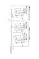
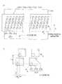
次に、ヘッドの構造について説明する。各ヘッド172M、172K、172C、172Yの構造は共通しているので、以下、これらを代表して符号250によってヘッドを示すものとする。図14(a) はヘッド250の構造例を示す平面透視図であり、図14(b) はその一部の拡大図である。また、図15はヘッド250の他の構造例を示す平面透視図、図16は記録素子単位となる1チャンネル分の液滴吐出素子(1つのノズル251に対応したインク室ユニット)の立体的構成を示す断面図(図14中のA−A線に沿う断面図)である。<Configuration example of inkjet head>
Next, the structure of the head will be described. Since the structures of the
図14に示したように、本例のヘッド250は、インク吐出口であるノズル251と、各ノズル251に対応する圧力室252等からなる複数のインク室ユニット(液滴吐出素子)253をマトリクス状に2次元配置させた構造を有し、これにより、ヘッド長手方向(紙送り方向と直交する方向)に沿って並ぶように投影(正射影)される実質的なノズル間隔(投影ノズルピッチ)の高密度化を達成している。 As shown in FIG. 14, the
記録媒体124の送り方向(矢印S方向;副走査方向)と略直交する方向(矢印M方向;主走査方向)に記録媒体124の描画領域の全幅Wmに対応する長さ以上のノズル列を構成する形態は本例に限定されない。例えば、図14(a) の構成に代えて、図15(a)に示すように、複数のノズル251が2次元に配列された短尺のヘッドモジュール250’を千鳥状に配列して繋ぎ合わせることで記録媒体124の全幅に対応する長さのノズル列を有するラインヘッドを構成する態様や、図15(b)に示すように、ヘッドモジュール250”を一列に並べて繋ぎ合わせる態様もある。 Nozzle rows having a length corresponding to the entire width Wm of the drawing area of the
なお、一つのヘッドモジュール250’、250”を本発明の「記録ヘッド」と解釈してもよいし、ヘッドモジュールを繋ぎ合わせた長尺ヘッドを「記録ヘッド」と解釈してもよい。 One
各ノズル251に対応して設けられている圧力室252は、その平面形状が概略正方形となっており(図14(a)、(b) 参照)、対角線上の両隅部の一方にノズル251への流出口が設けられ、他方に供給インクの流入口(供給口)254が設けられている。なお、圧力室252の形状は、本例に限定されず、平面形状が四角形(菱形、長方形など)、五角形、六角形その他の多角形、円形、楕円形など、多様な形態があり得る。 The
図16に示すように、ヘッド250は、ノズル251が形成されたノズルプレート251Aと、圧力室252や共通流路255等の流路が形成された流路板252P等を積層接合した構造から成る。ノズルプレート251Aは、ヘッド250のノズル面(インク吐出面)250Aを構成し、各圧力室252にそれぞれ連通する複数のノズル251が2次元的に形成されている。 As shown in FIG. 16, the
流路板252Pは、圧力室252の側壁部を構成するとともに、共通流路255から圧力室252にインクを導く個別供給路の絞り部(最狭窄部)としての供給口254を形成する流路形成部材である。なお、説明の便宜上、図16では簡略的に図示しているが、流路板252Pは一枚又は複数の基板を積層した構造である。 The
ノズルプレート251A及び流路板252Pは、シリコンを材料として半導体製造プロセスによって所要の形状に加工することが可能である。 The
共通流路255はインク供給源たるインクタンク(不図示)と連通しており、インクタンクから供給されるインクは共通流路255を介して各圧力室252に供給される。 The
圧力室252の一部の面(図16において天面)を構成する振動板256には、個別電極257を備えた圧電アクチュエータ258が接合されている。本例の振動板256は、圧電アクチュエータ258の下部電極に相当する共通電極259として機能するニッケル(Ni)導電層付きのシリコン(Si)から成り、各圧力室252に対応して配置される圧電アクチュエータ258の共通電極を兼ねる。なお、樹脂などの非導電性材料によって振動板を形成する態様も可能であり、この場合は、振動板部材の表面に金属などの導電材料による共通電極層が形成される。また、ステンレス鋼(SUS)など、金属(導電性材料)によって共通電極を兼ねる振動板を構成してもよい。 A
個別電極257に駆動電圧を印加することによって圧電アクチュエータ258が変形して圧力室252の容積が変化し、これに伴う圧力変化によりノズル251からインクが吐出される。インク吐出後、圧電アクチュエータ258が元の状態に戻る際、共通流路255から供給口254を通って新しいインクが圧力室252に再充填される。 By applying a driving voltage to the
かかる構造を有するインク室ユニット253を図14(b)に示す如く、主走査方向に沿う行方向及び主走査方向に対して直交しない一定の角度θを有する斜めの列方向に沿って一定の配列パターンで格子状に多数配列させることにより、本例の高密度ノズルヘッドが実現されている。かかるマトリクス配列において、副走査方向の隣接ノズル間隔をLsとするとき、主走査方向については実質的に各ノズル251が一定のピッチP=Ls/tanθで直線状に配列されたものと等価的に取り扱うことができる。 As shown in FIG. 14B, the
また、本発明の実施に際してヘッド250におけるノズル251の配列形態は図示の例に限定されず、様々なノズル配置構造を適用できる。例えば、図14で説明したマトリクス配列に代えて、一列の直線配列、V字状のノズル配列、V字状配列を繰り返し単位とするジグザク状(W字状など)のような折れ線状のノズル配列なども可能である。 In the implementation of the present invention, the arrangement form of the
なお、インクジェットヘッドにおける各ノズルから液滴を吐出させるための吐出用の圧力(吐出エネルギー)を発生させる手段は、圧電アクチュエータ(圧電素子)に限らず、サーマル方式(ヒータの加熱による膜沸騰の圧力を利用してインクを吐出させる方式)におけるヒータ(加熱素子)や他の方式による各種アクチュエータなど様々な圧力発生素子(エネルギー発生素子)を適用し得る。ヘッドの吐出方式に応じて、相応のエネルギー発生素子が流路構造体に設けられる。 The means for generating the discharge pressure (discharge energy) for discharging the droplets from each nozzle in the inkjet head is not limited to the piezoelectric actuator (piezoelectric element), but the thermal method (the pressure of film boiling due to the heating of the heater) Various pressure generating elements (energy generating elements) such as heaters (heating elements) and other actuators based on other systems can be applied. Corresponding energy generating elements are provided in the flow path structure according to the ejection method of the head.
<制御系の説明>
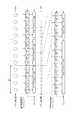
図17は、インクジェット記録装置100のシステム構成を示す要部ブロック図である。インクジェット記録装置100は、通信インターフェース270、システムコントローラ272、メモリ274、モータドライバ276、ヒータドライバ278、プリント制御部280、画像バッファメモリ282、ヘッドドライバ284等を備えている。<Description of control system>
FIG. 17 is a principal block diagram showing the system configuration of the
通信インターフェース270は、ホストコンピュータ286から送られてくる画像データを受信するインターフェース部である。通信インターフェース270にはCAN(Controller Area Network)、USB(Universal Serial Bus)、IEEE1394、イーサネット(登録商標)、無線ネットワーク等のシリアルインターフェースやセントロニクスなどのパラレルインターフェースを適用することができる。この部分には、通信を高速化するためのバッファメモリ(不図示)を搭載してもよい。ホストコンピュータ286から送出された画像データは通信インターフェース270を介してインクジェット記録装置100に取り込まれ、一旦メモリ274に記憶される。 The
メモリ274は、通信インターフェース270を介して入力された画像を一旦格納する記憶手段であり、システムコントローラ272を通じてデータの読み書きが行われる。メモリ274は、半導体素子からなるメモリに限らず、ハードディスクなど磁気媒体を用いてもよい。 The
システムコントローラ272は、中央演算処理装置(CPU)及びその周辺回路等から構成され、所定のプログラムに従ってインクジェット記録装置100の全体を制御する制御装置として機能するとともに、各種演算を行う演算装置として機能する。即ち、システムコントローラ272は、通信インターフェース270、メモリ274、モータドライバ276、ヒータドライバ278等の各部を制御し、ホストコンピュータ286との間の通信制御、メモリ274の読み書き制御等を行うとともに、搬送系のモータ288やヒータ289を制御する制御信号を生成する。 The
ROM290には各種制御プログラムや各種のパラメータ等が格納されており、システムコントローラ272の指令に応じて、制御プログラムが読み出され、実行される。 The
メモリ274は、画像データの一時記憶領域として利用されるとともに、プログラムの展開領域及びCPUの演算作業領域としても利用される。 The
モータドライバ276は、システムコントローラ272からの指示に従ってモータ288を駆動するドライバである。図15では、装置内の各部に配置される様々なモータを代表して符号288で図示している。 The
ヒータドライバ278は、システムコントローラ272からの指示に従って、ヒータ289を駆動するドライバである。図15では、装置内の各部に配置される様々なヒータを代表して符号289で図示している。 The
プリント制御部280は、システムコントローラ272の制御に従い、メモリ274内の画像データから印字制御用の信号を生成するための各種加工、補正などの処理を行う信号処理機能を有し、生成した印字データ(ドット画像データ)をヘッドドライバ284に供給する制御部である。 The
ドット画像データは、一般に多階調の画像データに対して色変換処理、ハーフトーン処理を行って生成される。色変換処理は、sRGBなどで表現された画像データ(例えば、RGB各色について8ビットの画像データ)をインクジェット記録装置100で使用するインクの各色の色データ(本例では、MKCYの色データ)に変換する処理である。 The dot image data is generally generated by performing color conversion processing and halftone processing on multi-gradation image data. In the color conversion process, image data expressed in sRGB or the like (for example, 8-bit image data for each RGB color) is converted into color data for each color of ink used in the inkjet recording apparatus 100 (in this example, color data for MKCY). It is a process to convert.
ハーフトーン処理は、色変換処理により生成された各色の色データに対して誤差拡散法や閾値マトリクス等の処理で各色のドットデータ(本例では、MKCYのドットデータ)に変換する処理である。 The halftone process is a process for converting color data of each color generated by the color conversion process into dot data of each color (in this example, MKCY dot data) by processes such as an error diffusion method and a threshold matrix.
プリント制御部280において所要の信号処理が施され、得られたドットデータに基づいて、ヘッドドライバ284を介してヘッド250のインク液滴の吐出量や吐出タイミングの制御が行われる。これにより、所望のドットサイズやドット配置が実現される。 The required signal processing is performed in the
プリント制御部280には画像バッファメモリ282が備えられており、プリント制御部280における画像データ処理時に画像データやパラメータなどのデータが画像バッファメモリ282に一時的に格納される。また、プリント制御部280とシステムコントローラ272とを統合して1つのプロセッサで構成する態様も可能である。 The
ヘッドドライバ284には、ヘッド250の駆動条件を一定に保つためのフィードバック制御系を含んでいてもよい。 The
本例に示すインクジェット記録装置100は、ヘッド250の各圧電アクチュエータ258に対して、共通の駆動波形信号を印加し、各ノズルの吐出タイミングに応じて各圧電アクチュエータ258の個別電極に接続されたスイッチ素子(不図示)のオンオフを切り換えることで、各圧電アクチュエータ258に対応するノズル251からインクを吐出させる駆動方式が採用されている。 The
エンコーダ277は、描画ドラム170の回転速度を検出するものであり、例えば光電方式のロータリエンコーダが用いられる。システムコントローラ272は、エンコーダ277からの信号に基づいて描画ドラム170の回転速度を算出し、算出した回転速度に基づいて各色のインクジェットヘッド172M,172K,172C,172Yのノズル251の吐出タイミング信号を生成し、プリント制御部280へ供給する。 The
プリント制御部280とシステムコントローラ272の組み合わせが図で説明した「制御装置90」に相当している。なお、図15で説明したシステムコントローラ272が担う処理機能の全て又は一部をホストコンピュータ286側に搭載する態様も可能である。 A combination of the
<記録媒体について>
「記録媒体」は、記録素子によってドットが記録される媒体の総称であり、印字媒体、被記録媒体、被画像形成媒体、受像媒体、被吐出媒体など様々な用語で呼ばれるものが含まれる。本発明の実施に際して、記録媒体の材質や形状等は、特に限定されず、連続用紙、カット紙、シール用紙、OHPシート等の樹脂シート、フィルム、布、不織布、配線パターン等が形成されるプリント基板、ゴムシート、その他材質や形状を問わず、様々な媒体に適用できる。<About recording media>
“Recording medium” is a generic term for media on which dots are recorded by a recording element, and includes media called by various terms such as a printing medium, a recording medium, an image forming medium, an image receiving medium, and an ejection medium. In the practice of the present invention, the material, shape, etc. of the recording medium are not particularly limited, and a print on which a resin sheet such as continuous paper, cut paper, seal paper, OHP sheet, film, cloth, nonwoven fabric, wiring pattern, or the like is formed. It can be applied to various media regardless of the substrate, rubber sheet, and other materials and shapes.
<ヘッドと用紙を相対移動させる手段について>
上述の実施形態では、停止したヘッドに対して記録媒体を搬送する構成を例示したが、本発明の実施に際しては、停止した記録媒体に対してヘッドを移動させる構成も可能である。なお、シングルパス方式のフルライン型の描画ヘッドは、通常、記録媒体の送り方向(搬送方向)と直交する方向に沿って配置されるが、搬送方向と直交する方向に対して、ある所定の角度を持たせた斜め方向に沿ってヘッドを配置する態様もあり得る。<Means for moving the head and paper relative to each other>
In the above-described embodiment, the configuration in which the recording medium is conveyed with respect to the stopped head has been exemplified. However, when the present invention is implemented, a configuration in which the head is moved with respect to the stopped recording medium is also possible. Note that the single-pass full-line drawing head is usually arranged along a direction perpendicular to the recording medium feeding direction (conveyance direction), but with respect to the direction perpendicular to the conveyance direction, There may be a mode in which the head is disposed along an oblique direction with an angle.
<ヘッド構成の変形例について>
上記実施形態では、記録媒体の全幅に対応する長さのノズル列を有するページワイドのフルライン型ヘッドを用いたインクジェット記録装置を説明したが、本発明の適用範囲はこれに限定されず、シリアル型(シャトルスキャン型)ヘッドなど、短尺の描画ヘッドを移動させながら、複数回のヘッド走査により画像記録を行うインクジェット記録装置についても本発明を適用可能である。<Modification of head configuration>
In the above embodiment, an inkjet recording apparatus using a page-wide full-line head having a nozzle row having a length corresponding to the entire width of the recording medium has been described. However, the scope of application of the present invention is not limited to this, and serial The present invention can also be applied to an ink jet recording apparatus that performs image recording by a plurality of head scans while moving a short drawing head such as a mold (shuttle scan type) head.
<本発明の応用例について>
上記の実施形態では、グラフィック印刷用のインクジェット記録装置への適用を例に説明したが、本発明の適用範囲はこの例に限定されない。例えば、電子回路の配線パターンを描画する配線記録装置、各種デバイスの製造装置、吐出用の機能性液体として樹脂液を用いるレジスト印刷装置、カラーフィルター製造装置、マテリアルデポジション用の材料を用いて微細構造物を形成する微細構造物形成装置など、液状機能性材料を用いて様々な形状やパターンを描画するインクジェットシステム(「液体吐出装置」に相当)に広く適用できる。<Application examples of the present invention>
In the above embodiment, application to an inkjet recording apparatus for graphic printing has been described as an example, but the scope of application of the present invention is not limited to this example. For example, a wiring recording device that draws a wiring pattern of an electronic circuit, a manufacturing device for various devices, a resist printing device that uses a resin liquid as a functional liquid for ejection, a color filter manufacturing device, and a material deposition material. The present invention can be widely applied to an inkjet system (corresponding to a “liquid ejecting apparatus”) that draws various shapes and patterns using a liquid functional material, such as a fine structure forming apparatus that forms a structure.
<インクジェット方式以外の記録ヘッドの利用形態について>
上述の説明では、記録ヘッドを用いる画像形成装置の一例としてインクジェット記録装置を例示したが、本発明の適用範囲はこれに限定されない。インクジェット方式以外では、サーマル素子を記録素子とする記録ヘッドを備えた熱転写記録装置、LED素子を記録素子とする記録ヘッドを備えたLED電子写真プリンタ、LEDライン露光ヘッドを有する銀塩写真方式プリンタなど、ドット記録を行う各種方式の画像形成装置についても本発明を適用することが可能である。<Usage of recording heads other than ink jet system>
In the above description, an ink jet recording apparatus is illustrated as an example of an image forming apparatus using a recording head, but the scope of application of the present invention is not limited to this. Other than the ink jet system, a thermal transfer recording apparatus including a recording head using a thermal element as a recording element, an LED electrophotographic printer including a recording head using an LED element as a recording element, and a silver salt photographic printer including an LED line exposure head The present invention can also be applied to various types of image forming apparatuses that perform dot recording.
<付記>
上記に詳述した発明の実施形態についての記載から把握されるとおり、本明細書は少なくとも以下に示す発明を含む多様な技術思想の開示を含んでいる。<Appendix>
As will be understood from the description of the embodiments of the invention described in detail above, the present specification includes disclosure of various technical ideas including at least the invention described below.
(発明1):複数の記録素子が直線上に配列された記録素子列と、前記記録素子列を構成する前記複数の記録素子を所定個数でグループ分けし、各グループに属する記録素子の記録タイミングをグループ単位で補正するためのブロック別補正値をカウントするブロックカウンタ回路と、同じグループ内に属する各記録素子の相対的な位置に応じて当該グループ内の各記録素子の記録タイミングを記録素子単位で補正するための個別補正値をカウントする個別カウンタ回路と、前記ブロックカウンタ回路に設定すべきブロック別補正値と前記個別カウンタ回路に設定すべき個別補正値とを含んだシリアルデータを受信し、当該シリアルデータを展開して前記ブロックカウンタ回路に前記ブロック別補正値を供給するとともに前記個別カウンタ回路に前記個別補正値を供給するデータ分配回路と、前記記録素子列に属する記録素子の記録タイミングの基準となる基準タイミングを示す基準起動信号を受信する基準起動信号受信部と、を備え、前記基準起動信号を基準に前記ブロックカウンタ回路及び前記個別カウンタ回路のうち少なくとも一方のカウントが開始され、前記ブロックカウンタ回路及び前記個別カウンタ回路を組み合わせたカウンタ回路によって前記ブロック別補正値と前記個別補正値とを結合させた補正量により補正タイミング信号が生成され、前記補正タイミング信号に従い前記記録素子による記録が行われることを特徴とする記録ヘッド。 (Invention 1): A recording element array in which a plurality of recording elements are arranged on a straight line and a plurality of recording elements constituting the recording element array are grouped by a predetermined number, and recording timing of recording elements belonging to each group A block counter circuit that counts the correction value for each block for correcting the image in a group unit, and the recording timing of each recording element in the group according to the relative position of each recording element in the same group Receiving serial data including an individual counter circuit that counts an individual correction value for correction in the block, a block-specific correction value to be set in the block counter circuit, and an individual correction value to be set in the individual counter circuit; The serial data is expanded, the correction value for each block is supplied to the block counter circuit, and the individual counter circuit is supplied. A data distribution circuit for supplying the individual correction value to a reference activation signal receiving unit for receiving a reference activation signal indicating a reference timing serving as a reference for recording timing of recording elements belonging to the recording element array, and the reference Counting of at least one of the block counter circuit and the individual counter circuit is started on the basis of an activation signal, and the correction value for each block and the individual correction value are determined by a counter circuit combining the block counter circuit and the individual counter circuit. A recording head, wherein a correction timing signal is generated with a correction amount obtained by combining the two, and recording is performed by the recording element in accordance with the correction timing signal.
本発明によれば、個別カウンタ回路にセットする個別補正値を各グループに共通化できるため、データ転送量を削減することができ、記録タイミングを補正するデータを効率良くデータ転送することができる。また、この発明によれば、記録素子列が斜めに配置されることによる記録位置のずれを効果的に補正するためのデータを効率良く転送することができる。 According to the present invention, since the individual correction value set in the individual counter circuit can be shared by each group, the data transfer amount can be reduced, and the data for correcting the recording timing can be efficiently transferred. Further, according to the present invention, it is possible to efficiently transfer data for effectively correcting the shift of the recording position due to the recording element array being arranged obliquely.
(発明2):発明1において、前記個別カウンタ回路に設定される前記個別補正値は、前記グループ分けされた各グループに対して共通であることを特徴とする記録ヘッド。 (Invention 2) The recording head according to
(発明3):発明1又は2において、前記記録素子列を複数列備え、これら複数列の記録素子列は互いに平行に配置されていることを特徴とする記録ヘッド。 (Invention 3): A recording head according to
かかる態様によれば、異なる記録素子列間で補正値の一部又は全部を共用することが可能である。 According to this aspect, it is possible to share part or all of the correction value between different printing element arrays.
(発明4):発明3において、前記複数列の記録素子列のうち、記録素子の配列密度が等しいものについて、それぞれの記録素子列に対応した前記ブロックカウンタ回路及び個別カウンタ回路に設定する前記ブロック別補正値及び前記個別補正値のデータは、同じ転送データが共用されることを特徴とする記録ヘッド。 (Invention 4): In the invention 3, the blocks set in the block counter circuit and the individual counter circuit corresponding to each recording element array for the plurality of recording element arrays having the same array density of the recording elements. The recording head, wherein the same transfer data is shared as the data of the separate correction value and the individual correction value.
かかる態様によれば、データ転送量を一層の削減することができる。 According to this aspect, the data transfer amount can be further reduced.
(発明5):発明3において、配列密度が異なる複数列の前記記録素子列を備え、各記録素子列の記録素子を同じ個数でグループ分けし、各記録素子列に対応した前記個別カウンタ回路に対し、記録素子列毎に前記配列密度に応じた個別補正値が設定されることを特徴とする記録ヘッド。 (Invention 5): In Invention 3, a plurality of the recording element arrays having different arrangement densities are provided, the recording elements of each recording element array are grouped by the same number, and the individual counter circuit corresponding to each recording element array is provided. On the other hand, an individual correction value corresponding to the arrangement density is set for each printing element array.
かかる態様によれば、異なる記録素子列間でブロック別補正値の一部又は全部を共通化することができる。 According to this aspect, some or all of the correction values for each block can be shared between different printing element arrays.
(発明6):発明3において、配列密度が異なる複数列の前記記録素子列を備え、これら複数列のうち配列密度が相対的に低い列のグループ内における両端の記録素子の位置に合わせて、配列密度が相対的に高い列の記録素子がグループ分けされ、各列のブロックカウンタ回路のブロック別補正値が共用されることを特徴とする記録ヘッド。 (Invention 6): In Invention 3, the recording element rows having a plurality of rows having different arrangement densities are provided, and in accordance with the positions of the recording elements at both ends in a group of rows having a relatively low arrangement density among the plurality of rows, A recording head characterized in that recording elements in a column having a relatively high arrangement density are grouped, and the correction value for each block of the block counter circuit in each column is shared.
かかる態様によれば、異なる記録素子列間でブロック別補正値の一部又は全部を共通化することができ、データ転送量を削減できる。 According to this aspect, some or all of the correction values for each block can be shared between different printing element arrays, and the data transfer amount can be reduced.
(発明7):発明3において、配列密度が異なる複数列の前記記録素子列を備え、これら複数列のうち基準となる配列密度に対する各列の配列密度の割合に応じて、当該記録素子列の前記ブロックカウンタ回路及び前記個別カウンタ回路に与えるクロック信号のクロック周波数が変更され、各列に共通の前記ブロック別補正値及び前記個別補正値が前記シリアルデータで受信されることを特徴とする記録ヘッド。 (Invention 7): In Invention 3, a plurality of the recording element arrays having different array densities are provided, and according to the ratio of the array density of each array to the reference array density among the plurality of arrays, the recording element array A recording head in which a clock frequency of a clock signal applied to the block counter circuit and the individual counter circuit is changed, and the block-specific correction value and the individual correction value common to each column are received as the serial data. .
かかる態様によれば、異なる記録素子列に対するブロック別補正値及び個別補正値を共通化することができるため、データ転送量を削減できる。 According to this aspect, the block-specific correction values and the individual correction values for the different printing element arrays can be shared, so that the data transfer amount can be reduced.
(発明8):発明3から7のいずれか1項において、前記複数列の記録素子列のうち、当該記録ヘッドに対する記録媒体の相対的な移動方向に対して、最上流に位置する記録素子列の基準起動信号を各記録素子列共通の基準起動信号として用いることを特徴とする記録ヘッド。 (Invention 8): In any one of Inventions 3 to 7, among the plurality of recording element arrays, the recording element array positioned on the uppermost stream with respect to the relative movement direction of the recording medium with respect to the recording head. The reference start signal is used as a reference start signal common to the recording element arrays.
停止した記録ヘッドに対して記録媒体を搬送する形態の場合には、記録媒体の搬送方向に対して、第1列目となる記録素子列の基準起動信号を、他の列にも共通に用いることができる。 In the case where the recording medium is transported to the stopped recording head, the reference activation signal of the recording element array serving as the first array is commonly used for the other arrays in the recording medium transport direction. be able to.
(発明9):発明1から8のいずれか1項において、前記データ分配回路は、前記基準起動信号の受信に先立ち、予め転送されてくる各ブロックカウンタ回路のブロック別補正値と各個別カウンタ回路の個別補正値をシリアルデータで受信し、当該シリアルデータ内のデータアドレス値によって各カウンタ回路へデータを分配することを特徴とする記録ヘッド。 (Invention 9): In any one of the
補正値を示すデータは、記録ヘッドの初期化時など、予め記録ヘッドに転送され、各カウンタ回路にセットすることができる。 Data indicating the correction value is transferred to the print head in advance, such as when the print head is initialized, and can be set in each counter circuit.
(発明10):発明9において、前記データ分配回路は、シフトレジスタ回路と、前記シリアルデータから前記シフトレジスタ回路を介して各記録素子のブロック別補正値及び個別補正値に対応するカウントデータを展開するデコーダ回路と、前記展開されたカウントデータを保持するラッチ回路と、から構成されていることを特徴とする記録ヘッド。 (Invention 10): In invention 9, the data distribution circuit develops a shift register circuit and count data corresponding to the correction value for each block and the individual correction value of each printing element from the serial data via the shift register circuit. And a latch circuit for holding the expanded count data.
(発明11):発明1から10のいずれか1項において、前記シリアルデータとして、前記記録ヘッドに含まれる複数の記録素子のうち、記録タイミングの補正が必要な記録素子の補正用データ、或いは、補正値の修正が必要な記録素子の修正用データのみが前記記録ヘッドに転送されることを特徴とする記録ヘッド。 (Invention 11): In any one of
かかる態様によれば、データ転送量の一層の削減が可能である。 According to this aspect, the data transfer amount can be further reduced.
(発明12):発明1から11のいずれか1項において、配列密度が異なる複数列の前記記録素子列を備え、前記データ分配回路へ転送される前記シリアルデータは、同じ配列密度の記録素子列に対して共通に記録タイミングを補正する場合において、記録素子列の配列密度に応じたコードデータがアドレスの上位ビットに付加されることを特徴とする記録ヘッド。 (Invention 12): In any one of
(発明13):発明1から12のいずれか1項において、前記記録素子列を複数列備え、前記データ分配回路へ転送される前記シリアルデータは、各記録素子列毎に記録タイミングを補正する場合において、前記シリアルデータのヘッダーの記録素子列を識別するコードデータが付加されることを特徴とする記録ヘッド。 (Invention 13): The invention according to any one of
この場合、記録素子列を識別するコードデータは、記録タイミングの補正用のカウントデータと同様の方法で展開され、該当する記録素子列のカウントデータ出力のON/OFFに利用される。 In this case, the code data for identifying the printing element array is developed in the same manner as the recording timing correction count data, and is used for ON / OFF of the count data output of the corresponding printing element array.
(発明14):発明1から13のいずれか1項において、前記記録素子は、ノズルから液滴を吐出して、その吐出液滴により記録媒体上にドットを記録する液滴吐出素子であることを特徴とする記録ヘッド。 (Invention 14): In any one of
記録ヘットとして、インクジェットヘッド(液体吐出ヘッド)を用いることができる。この場合、ノズル列におけるノズルのグループ分けは、実質的には、ノズルに対応した吐出エネルギー発生素子をグループ分けすることに相当する。 An ink jet head (liquid discharge head) can be used as the recording head. In this case, the grouping of the nozzles in the nozzle row substantially corresponds to grouping the ejection energy generating elements corresponding to the nozzles.
(発明15):発明1から14のいずれか1項に記載の記録ヘッドと、前記記録ヘッドに対して前記シリアルデータを送信する制御装置と、を備えたことを特徴とする画像形成装置。 (Invention 15): An image forming apparatus comprising: the recording head according to any one of
制御装置から記録ヘッドにシリアルデータを転送する際に、データ転送量を削減することが可能である。 When transferring serial data from the control device to the recording head, it is possible to reduce the data transfer amount.
(発明16):発明14に記載の記録ヘッドと、前記記録ヘッドに対して前記シリアルデータを送信する制御装置と、を備えたことを特徴とする液体吐出装置。 (Invention 16): A liquid ejection apparatus comprising: the recording head according to Invention 14; and a control device that transmits the serial data to the recording head.
記録ヘッドとして液体吐出ヘッドを採用した形態においては、当該液体吐出ヘッドと制御装置とを組み合わせることで液体吐出装置が実現される。 In the form in which the liquid discharge head is employed as the recording head, the liquid discharge apparatus is realized by combining the liquid discharge head and the control device.
10-1〜10-12…ノズル、40…記録ヘッド、42…シフトレジスタ回路、44…デコーダ回路、46…ラッチ回路、48…個別カウンタ回路、50…ブロックカウンタ回路、54…スイッチ素子、56…記録素子、60…シリアルデータ入力端子、66…基準起動信号入力端子、70…データ分配回路、90…制御装置、95…インクジェット記録装置、100…インクジェット記録装置、124…記録媒体、170…描画ドラム、172M,172K,172C,172Y…インクジェットヘッド(記録ヘッド)、250’,250”…ヘッドモジュール、251…ノズル、272…システムコントローラ、280…プリント制御部 10-1 to 10-12
Claims (15)
Translated fromJapanese前記記録素子列を構成する前記複数の記録素子を所定個数でグループ分けし、各グループに属する記録素子の記録タイミングをグループ単位で補正するためのブロック別補正値をカウントするブロックカウンタ回路と、
同じグループ内に属する各記録素子の相対的な位置に応じて当該グループ内の各記録素子の記録タイミングを記録素子単位で補正するための個別補正値をカウントする個別カウンタ回路と、
前記ブロックカウンタ回路に設定すべきブロック別補正値と前記個別カウンタ回路に設定すべき個別補正値とを含んだシリアルデータを受信し、当該シリアルデータを展開して前記ブロックカウンタ回路に前記ブロック別補正値を供給するとともに前記個別カウンタ回路に前記個別補正値を供給するデータ分配回路と、
前記記録素子列に属する記録素子の記録タイミングの基準となる基準タイミングを示す基準起動信号を受信する基準起動信号受信部と、を備え、
前記個別カウンタ回路に設定される前記個別補正値は、前記グループ分けされた各グループに対して共通であり、
前記各グループの前記個別カウンタ回路に設定される前記個別補正値のデータは、同じ転送データが共用され、
前記基準起動信号を基準に前記ブロックカウンタ回路及び前記個別カウンタ回路のうち少なくとも一方のカウントが開始され、前記ブロックカウンタ回路及び前記個別カウンタ回路を組み合わせたカウンタ回路によって前記ブロック別補正値と前記個別補正値とを結合させた補正量により補正タイミング信号が生成され、
前記補正タイミング信号に従い前記記録素子による記録が行われることを特徴とする記録ヘッド。A recording element array in which a plurality of recording elements are arranged on a straight line;
A block counter circuit that groups the plurality of recording elements constituting the recording element array in a predetermined number and counts a correction value for each block for correcting the recording timing of the recording elements belonging to each group in units of groups;
An individual counter circuit that counts an individual correction value for correcting the recording timing of each recording element in the group according to the relative position of each recording element in the same group; and
Serial data including a block-specific correction value to be set in the block counter circuit and an individual correction value to be set in the individual counter circuit is received, the serial data is expanded, and the block correction is performed in the block counter circuit A data distribution circuit for supplying a value and supplying the individual correction value to the individual counter circuit;
A reference activation signal receiving unit that receives a reference activation signal indicating a reference timing that serves as a reference for recording timing of recording elements belonging to the recording element array, and
The individual correction value set in the individual counter circuit is common to the grouped groups,
The same transfer data is shared as the individual correction value data set in the individual counter circuit of each group,
Counting of at least one of the block counter circuit and the individual counter circuit is started based on the reference activation signal, and the correction value for each block and the individual correction are performed by a counter circuit combining the block counter circuit and the individual counter circuit. A correction timing signal is generated by the correction amount obtained by combining the value,
A recording head, wherein recording is performed by the recording element in accordance with the correction timing signal.
シフトレジスタ回路と、
前記シリアルデータから前記シフトレジスタ回路を介して各記録素子のブロック別補正値及び個別補正値に対応するカウントデータを展開するデコーダ回路と、
前記展開されたカウントデータを保持するラッチ回路と、
から構成されていることを特徴とする請求項8に記載の記録ヘッド。The data distribution circuit includes:
A shift register circuit;
A decoder circuit that expands the count data corresponding to the block-specific correction value and the individual correction value of each printing element from the serial data via the shift register circuit;
A latch circuit for holding the expanded count data;
The recording head according to claim8 , comprising:
前記データ分配回路へ転送される前記シリアルデータは、同じ配列密度の記録素子列に対して共通に記録タイミングを補正する場合において、記録素子列の配列密度に応じたコードデータがアドレスの上位ビットに付加されることを特徴とする請求項1から10のいずれか1項に記載の記録ヘッド。A plurality of the recording element rows having different arrangement densities;
The serial data transferred to the data distribution circuit has code data corresponding to the arrangement density of the recording element arrays in the upper bits of the address when the recording timing is corrected in common for the recording element arrays of the same arrangement density. recording head according to claim 1, any one of10, wherein the added is that.
前記記録ヘッドに対して前記シリアルデータを送信する制御装置と、
を備えたことを特徴とする画像形成装置。The recording head according to any one of claims 1 to13 ,
A control device for transmitting the serial data to the recording head;
An image forming apparatus comprising:
前記記録ヘッドに対して前記シリアルデータを送信する制御装置と、
を備えたことを特徴とする液体吐出装置。A recording head according to claim13 ;
A control device for transmitting the serial data to the recording head;
A liquid ejection apparatus comprising:
Priority Applications (1)
| Application Number | Priority Date | Filing Date | Title |
|---|---|---|---|
| JP2011002993AJP5649460B2 (en) | 2011-01-11 | 2011-01-11 | Recording head, image forming apparatus, and liquid ejection apparatus |
Applications Claiming Priority (1)
| Application Number | Priority Date | Filing Date | Title |
|---|---|---|---|
| JP2011002993AJP5649460B2 (en) | 2011-01-11 | 2011-01-11 | Recording head, image forming apparatus, and liquid ejection apparatus |
Publications (2)
| Publication Number | Publication Date |
|---|---|
| JP2012143935A JP2012143935A (en) | 2012-08-02 |
| JP5649460B2true JP5649460B2 (en) | 2015-01-07 |
Family
ID=46788027
Family Applications (1)
| Application Number | Title | Priority Date | Filing Date |
|---|---|---|---|
| JP2011002993AExpired - Fee RelatedJP5649460B2 (en) | 2011-01-11 | 2011-01-11 | Recording head, image forming apparatus, and liquid ejection apparatus |
Country Status (1)
| Country | Link |
|---|---|
| JP (1) | JP5649460B2 (en) |
Family Cites Families (9)
| Publication number | Priority date | Publication date | Assignee | Title |
|---|---|---|---|---|
| JPH0793671B2 (en)* | 1984-03-27 | 1995-10-09 | キヤノン株式会社 | Recording control device |
| JPH09174843A (en)* | 1995-12-25 | 1997-07-08 | Canon Inc | Printing head and printing apparatus using the printing head |
| JPH09131876A (en)* | 1996-10-21 | 1997-05-20 | Canon Inc | Inkjet head |
| JPH1142803A (en)* | 1997-07-29 | 1999-02-16 | Brother Ind Ltd | Thermal printer |
| JP3564024B2 (en)* | 1998-12-21 | 2004-09-08 | キヤノン株式会社 | Recording head and recording apparatus using the recording head |
| JP2000263770A (en)* | 1999-03-16 | 2000-09-26 | Canon Inc | Recording device |
| EP2065197B1 (en)* | 2006-09-20 | 2017-03-01 | Konica Minolta Holdings, Inc. | Ink jet head driving apparatus |
| JP2008246859A (en)* | 2007-03-30 | 2008-10-16 | Kyocera Mita Corp | Position correcting system and position correcting method |
| JP2009006677A (en)* | 2007-06-29 | 2009-01-15 | Canon Inc | Recording device |
- 2011
- 2011-01-11JPJP2011002993Apatent/JP5649460B2/ennot_activeExpired - Fee Related
Also Published As
| Publication number | Publication date |
|---|---|
| JP2012143935A (en) | 2012-08-02 |
Similar Documents
| Publication | Publication Date | Title |
|---|---|---|
| JP5433476B2 (en) | Image processing method and apparatus, inkjet drawing apparatus, and correction coefficient data generation method | |
| JP5473704B2 (en) | Test pattern printing method and inkjet recording apparatus | |
| JP5158992B2 (en) | Defect recording element detection apparatus and method, and image forming apparatus | |
| JP5477954B2 (en) | Image recording apparatus and head adjustment method of image recording apparatus | |
| JP5832369B2 (en) | Inkjet recording device | |
| JP5952704B2 (en) | Head driving method, head driving device, and ink jet recording apparatus | |
| JP5968797B2 (en) | Head adjustment method, head drive device, and image forming apparatus | |
| JP2009241316A (en) | Liquid droplet delivering device | |
| US9370954B2 (en) | Method for measuring amount of positional deviation and image-recording device | |
| JP2014136319A (en) | Method for detecting position displacement of recording head, and image recording device | |
| JP5354801B2 (en) | Head control apparatus and inkjet recording apparatus | |
| JP2012035573A (en) | Liquid discharge head, and image recording device and method | |
| JP2012250472A (en) | State monitoring device of inkjet recording head and inkjet recording apparatus | |
| JP6461839B2 (en) | Recording head adjustment method and image forming apparatus | |
| JP5393560B2 (en) | Inkjet drawing apparatus, design method thereof, and drawing quality improvement method | |
| JP5393561B2 (en) | Inkjet drawing apparatus, design method thereof, and drawing quality improvement method | |
| JP5649460B2 (en) | Recording head, image forming apparatus, and liquid ejection apparatus | |
| WO2013168781A1 (en) | Image recording device and image recording method | |
| JP5393562B2 (en) | Inkjet drawing apparatus, design method thereof, and drawing quality improvement method | |
| JP5313182B2 (en) | Image forming apparatus and method | |
| JP7732852B2 (en) | Recording head control device and control method, and printing device | |
| JP2012139987A (en) | Liquid ejection head and image recording apparatus | |
| JP2012076301A (en) | Image forming apparatus and method | |
| JP2010234551A (en) | Image forming apparatus | |
| JP5657432B2 (en) | Image generating apparatus and method, and image forming apparatus |
Legal Events
| Date | Code | Title | Description |
|---|---|---|---|
| A621 | Written request for application examination | Free format text:JAPANESE INTERMEDIATE CODE: A621 Effective date:20130702 | |
| A977 | Report on retrieval | Free format text:JAPANESE INTERMEDIATE CODE: A971007 Effective date:20140131 | |
| A131 | Notification of reasons for refusal | Free format text:JAPANESE INTERMEDIATE CODE: A131 Effective date:20140204 | |
| A521 | Request for written amendment filed | Free format text:JAPANESE INTERMEDIATE CODE: A523 Effective date:20140402 | |
| TRDD | Decision of grant or rejection written | ||
| A01 | Written decision to grant a patent or to grant a registration (utility model) | Free format text:JAPANESE INTERMEDIATE CODE: A01 Effective date:20141110 | |
| A61 | First payment of annual fees (during grant procedure) | Free format text:JAPANESE INTERMEDIATE CODE: A61 Effective date:20141111 | |
| R150 | Certificate of patent or registration of utility model | Ref document number:5649460 Country of ref document:JP Free format text:JAPANESE INTERMEDIATE CODE: R150 | |
| R250 | Receipt of annual fees | Free format text:JAPANESE INTERMEDIATE CODE: R250 | |
| R250 | Receipt of annual fees | Free format text:JAPANESE INTERMEDIATE CODE: R250 | |
| R250 | Receipt of annual fees | Free format text:JAPANESE INTERMEDIATE CODE: R250 | |
| R250 | Receipt of annual fees | Free format text:JAPANESE INTERMEDIATE CODE: R250 | |
| LAPS | Cancellation because of no payment of annual fees |