Movatterモバイル変換


[0]ホーム

URL:


JP5648970B2 - Impact tools - Google Patents

Impact tools
Download PDF

Info

Publication number
JP5648970B2
JP5648970B2JP2010266094AJP2010266094AJP5648970B2JP 5648970 B2JP5648970 B2JP 5648970B2JP 2010266094 AJP2010266094 AJP 2010266094AJP 2010266094 AJP2010266094 AJP 2010266094AJP 5648970 B2JP5648970 B2JP 5648970B2
Authority
JP
Japan
Prior art keywords
hammer
motor
anvil
rotation
rotation angle
Prior art date
Legal status (The legal status is an assumption and is not a legal conclusion. Google has not performed a legal analysis and makes no representation as to the accuracy of the status listed.)
Expired - Fee Related
Application number
JP2010266094A
Other languages
Japanese (ja)
Other versions
JP2012115926A (en
Inventor
弘識 益子
弘識 益子
西河 智雅
智雅 西河
高野 信宏
信宏 高野
Current Assignee (The listed assignees may be inaccurate. Google has not performed a legal analysis and makes no representation or warranty as to the accuracy of the list.)
Koki Holdings Co Ltd
Original Assignee
Hitachi Koki Co Ltd
Priority date (The priority date is an assumption and is not a legal conclusion. Google has not performed a legal analysis and makes no representation as to the accuracy of the date listed.)
Filing date
Publication date
Application filed by Hitachi Koki Co LtdfiledCriticalHitachi Koki Co Ltd
Priority to JP2010266094ApriorityCriticalpatent/JP5648970B2/en
Priority to CN201110397500XAprioritypatent/CN103009349A/en
Priority to DE102011055874Aprioritypatent/DE102011055874A1/en
Priority to US13/307,490prioritypatent/US20120234566A1/en
Publication of JP2012115926ApublicationCriticalpatent/JP2012115926A/en
Application grantedgrantedCritical
Publication of JP5648970B2publicationCriticalpatent/JP5648970B2/en
Expired - Fee Relatedlegal-statusCriticalCurrent
Anticipated expirationlegal-statusCritical

Links

Images

Landscapes

Description

Translated fromJapanese

本発明は、モータにより駆動され、減速機構を介して先端工具を回転させるインパクト工具に関し、特にモータの駆動制御を工夫してシンプルな打撃機構を駆動することにより効率的に打撃動作を行うことができるインパクト工具を実現することにある。  The present invention relates to an impact tool that is driven by a motor and rotates a tip tool via a speed reduction mechanism, and in particular, can perform a striking operation efficiently by driving a simple striking mechanism by devising drive control of the motor. It is to realize a possible impact tool.

インパクト工具は、モータを駆動源として回転打撃機構部を駆動し、アンビルに回転力と打撃力を与えることによって先端工具に回転打撃力を間欠的に伝達してネジ締め等の作業を行うものである。近年、駆動源としてブラシレスDCモータが広く用いられるようになってきた。ブラシレスDCモータは、例えばブラシ(整流用刷子)の無いDC(直流)モータであり、コイル(巻線)を固定子側に、マグネット(永久磁石)を回転子側に用い、インバータ回路で駆動された電力を所定のコイルへ順次通電することによりロータを回転させる。インバータ回路は、FET(電界効果トランジスタ)や、IGBT(絶縁ゲートバイポーラトランジスタ)のような大容量の出力トランジスタを使用して構成され、大電流で駆動される。ブラシレスDCモータは、ブラシ付きDCモータと比較するとトルク特性に優れ、より強い力で被加工部材にネジやボルト等を締め付けることができる。  The impact tool drives the rotary impact mechanism using a motor as a drive source, and intermittently transmits the rotary impact force to the tip tool by applying rotational force and impact force to the anvil to perform operations such as screw tightening. is there. In recent years, brushless DC motors have been widely used as drive sources. The brushless DC motor is, for example, a DC (direct current) motor without a brush (rectifying brush), and is driven by an inverter circuit using a coil (winding) on the stator side and a magnet (permanent magnet) on the rotor side. The rotor is rotated by sequentially energizing the predetermined power to a predetermined coil. The inverter circuit is configured using a large-capacity output transistor such as an FET (Field Effect Transistor) or an IGBT (Insulated Gate Bipolar Transistor), and is driven with a large current. A brushless DC motor is excellent in torque characteristics as compared with a brushed DC motor, and can tighten a screw, a bolt, or the like on a workpiece by a stronger force.

ブラシレスDCモータを用いたインパクト工具の例として、例えば特許文献1の技術が知られている。特許文献1では、連続回転式の打撃機構部を有し、動力伝達機構部(減速機構部)を介してスピンドルに回転力が与えられると、スピンドルの回転軸方向に移動可能に係合するハンマが回転し、ハンマと当接するアンビルを回転させる。ハンマとアンビルは、回転平面上の2箇所に互いに対称的に配置された2つのハンマ凸部(打撃部)をそれぞれ有し、これらの凸部は互いに回転方向に噛み合う位置にあり、凸部同士の噛み合いにより回転打撃力が伝えられる。ハンマは、スピンドルを囲むリング域で、スピンドルに対して軸方向に摺動自在にされ、ハンマの内周面には、逆V字型(略三角形)のカム溝が設けられる。スピンドルの外周面には軸方向に、V字型のカム溝が設けられており、このカム溝とハンマの内周カム溝との間に挿入されたボール(鋼球)を介してハンマが回転する。  As an example of an impact tool using a brushless DC motor, for example, the technique ofPatent Document 1 is known. InPatent Document 1, a hammer that has a continuously rotating striking mechanism portion and engages movably in the direction of the rotation axis of the spindle when a rotational force is applied to the spindle via a power transmission mechanism portion (deceleration mechanism portion). Rotates and rotates the anvil that contacts the hammer. The hammer and the anvil each have two hammer protrusions (striking parts) arranged symmetrically with each other at two locations on the plane of rotation, and these protrusions are in positions that mesh with each other in the rotation direction. Rotating impact force is transmitted by the meshing. The hammer is slidable in the axial direction with respect to the spindle in a ring region surrounding the spindle, and an inverted V-shaped (substantially triangular) cam groove is provided on the inner peripheral surface of the hammer. A V-shaped cam groove is provided in the axial direction on the outer peripheral surface of the spindle, and the hammer rotates via a ball (steel ball) inserted between the cam groove and the inner peripheral cam groove of the hammer. To do.

特許第2008−307664号公報Japanese Patent No. 2008-307664

従来の動力伝達機構部においては、スピンドルとハンマは、カム溝に配置されたボールを介して保持され、ハンマはその後端に配置されるスプリングによって、スピンドルに対して軸方向後方に後退できるように構成されている。従って、スピンドルとハンマの部分の部品点数が多くなり、スピンドルとハンマの間の取り付け精度を良くするように考慮しなければならないので、製造コストが高くなっていた。  In the conventional power transmission mechanism, the spindle and the hammer are held via a ball disposed in the cam groove, and the hammer can be moved backward in the axial direction with respect to the spindle by a spring disposed at the rear end. It is configured. Therefore, the number of parts of the spindle and the hammer portion increases, and it is necessary to consider so as to improve the mounting accuracy between the spindle and the hammer, so that the manufacturing cost is high.

また、特許文献1の技術において、ハンマによる打撃時には、先端工具の負荷状態にかかわらず、モータに供給する駆動電力は一定であった。したがって、軽負荷状態でも高い締め付けトルクで打撃することになり、モータに過剰な電力を供給することになって、無駄な電力消費が生じていた。  Further, in the technique ofPatent Document 1, when the hammer is struck, the driving power supplied to the motor is constant regardless of the load state of the tip tool. Therefore, even a light load state is hit with a high tightening torque, and excessive electric power is supplied to the motor, resulting in unnecessary power consumption.

本発明は上記背景に鑑みてなされたもので、その目的は、新規な打撃機構を用い、モータの正回転及び逆回転を繰り返しながら先端工具を回転させるインパクト工具を提供することにある。  The present invention has been made in view of the above background, and an object of the present invention is to provide an impact tool that rotates a tip tool while repeating forward and reverse rotations of a motor using a novel striking mechanism.

本発明の別の目的は、ホール素子を有するブラシレスモータを駆動源として用い、ホース素子の出力信号を用いてハンマがアンビルを打撃するまでの回転角度の制御を行い、ハンマ逆転のストロークを最大限に確保し、高トルクを出力するための最適な打撃制御を行うようにしたインパクト工具を提供することにある。  Another object of the present invention is to use a brushless motor having a Hall element as a drive source, and to control the rotation angle until the hammer strikes the anvil using the output signal of the hose element to maximize the stroke of the hammer reversal. It is an object of the present invention to provide an impact tool that performs optimal striking control for ensuring high torque output.

本発明のさらに別の目的は、ハンマがアンビルを打撃するタイミングの近傍で、モータを回転させるための電力供給を停止する制御を行い、過剰なモータ電流と反動を抑制できるインパクト工具を提供することにある。  Still another object of the present invention is to provide an impact tool that performs control to stop the power supply for rotating the motor in the vicinity of the timing when the hammer strikes the anvil, and can suppress excessive motor current and reaction. It is in.

本願において開示される発明のうち、代表的なものの特徴を説明すれば、次の通りである。  Of the inventions disclosed in the present application, typical features will be described as follows.

本発明の一つ特徴によれば、回転子と、固定子と、回転子の回転位置を検出する回転位置検出素子を有するモータと、モータに回転駆動されるハンマと、ハンマと1回転未満の相対回転が可能であってハンマによって打撃されるアンビルと、アンビルに接続される出力軸を有しハンマを所定量逆転させた後にハンマを所定量正転させることによってハンマをアンビルに打撃させるようにしたインパクト工具において、逆転及び正転させるハンマの所定量を、回転位置検出素子の出力に基づいて得られる回転角度によって制御するように構成した。また、モータの回転を制御する制御部を設け、制御部はハンマの連続正転駆動の角度変化率が所定値未満になった後に、ハンマを逆転及び正転させる断続駆動制御を開始するようにした。  According to one aspect of the present invention, a rotor, a stator, a motor having a rotational position detecting element for detecting the rotational position of the rotor, a hammer driven to rotate by the motor, and the hammer less than one rotation. An anvil which can be rotated relative to the anvil and has an output shaft connected to the anvil, and the hammer is caused to strike the anvil by rotating the hammer forward by a predetermined amount after rotating the hammer a predetermined amount. In the impact tool, the predetermined amount of the hammer to be reversely rotated and forwardly rotated is controlled by the rotation angle obtained based on the output of the rotation position detecting element. In addition, a control unit for controlling the rotation of the motor is provided, and the control unit starts intermittent drive control to reverse and forward the hammer after the angle change rate of the continuous forward rotation of the hammer becomes less than a predetermined value. did.

本発明の他の特徴によれば、制御部はハンマの逆転開始位置を記憶し、ハンマを逆転させた後に正転させて、ハンマが再び逆転開始位置付近に到達したら、モータの正転方向の駆動電圧の供給を停止させるように制御する。逆転開始位置付近への到達は、回転子の逆転角度及び正転角度を算出することによって検出される。ハンマは、減速機構を介してモータに接続され、ハンマの正転角度及び逆転角度は、モータへの回転角度に減速機構の減速比を乗じて算出される。  According to another feature of the present invention, the controller stores the reverse rotation start position of the hammer, reverses the hammer, rotates forward, and once the hammer reaches again the vicinity of the reverse rotation start position, Control is performed to stop the supply of the drive voltage. The arrival near the reverse rotation start position is detected by calculating the reverse rotation angle and the normal rotation angle of the rotor. The hammer is connected to the motor via a reduction mechanism, and the normal rotation angle and reverse rotation angle of the hammer are calculated by multiplying the rotation angle to the motor by the reduction ratio of the reduction mechanism.

本発明のさらに他の特徴によれば、モータと、モータに接続されるハンマと、ハンマによって回転するアンビルと、モータの回転を制御する制御部を有し、ハンマによってアンビルを打撃して回転させるインパクト工具であって、制御部はハンマがアンビルを打撃する直前にモータへの駆動電圧の供給を停止させる。つまり打撃をするときは、モータは惰性で回転している状態となる。制御部は、モータを正方向と逆方向に交互に回転しながらアンビルを打撃して回転させると好ましい。ハンマの回転角は、モータの回転位置検出用のセンサ出力を用いて検出され、ハンマを所定角度だけ逆転駆動させた後に、ハンマを逆転角度と同じか又はそれよりやや少ない角度だけモータで正転駆動させるように制御する。モータとハンマはギアを介して連結され、モータの回転数はハンマの回転数より高くなる。According to still another aspect of the present invention, a motor, a hammer connected to the motor, an anvil rotated by the hammer, and a control unit for controlling the rotation of the motor are hit, and the anvil is hit and rotated by the hammer. In the impact tool, the control unit stops the supply of the drive voltage to the motorimmediately before the hammer strikes the anvil. That is, when hitting, the motor is in a state of rotating by inertia. The control unit preferably strikes and rotates the anvil while rotating themotor alternately in the forward direction and the reverse direction. The rotation angle of the hammer is detected by using the sensor output for detecting the rotational position of the motor. After the hammer is driven in reverse by a predetermined angle, the hammer is rotated forward by the motor by an angle equal to or slightly less than the reverse rotation angle. Control to drive. The motor and the hammer are connected via a gear, and the rotational speed of the motor is higher than the rotational speed of the hammer.

請求項1の発明によれば、ハンマを正方向と逆方向に交互に回転しながらアンビルを打撃して回転させるインパクト工具において、逆転及び正転させるハンマの所定量を、回転位置検出素子の出力に基づいて得られる回転角度によって制御するので、ハンマとアンビルの相対回転が可能なストローク(移動可能範囲)のほとんど全部を逆転及び加速用に用いることができるので、ハンマの加速区間を大きく取ることができる。このため、ハンマの慣性エネルギーを大きくできるので、出力軸から得られる打撃トルクを大きくすることができる。また、制御部はハンマの逆転開始位置を記憶し、ハンマを逆転させた後に正転させて、ハンマが再び逆転開始位置付近に到達したら、モータの正転方向の駆動電圧の供給を停止させるので、ハンマの慣性エネルギーのみでアンビルを打撃するので、効率的に打撃を行うことができる。仮に逆回転位置を過ぎてもハンマの正転を続けてしまうと、ハンマの慣性エネルギーのみならず、モータによる回転出力によってアンビルを駆動してしまうことになり、エネルギーのロスが大きくなる。According to the first aspect of the present invention, in the impact tool for striking and rotating the anvil while rotating the hammer alternately in the forward direction and the reverse direction, the predetermined amount of the hammer to be rotated in the reverse direction and the forward direction is output from the rotational position detecting element. Because it is controlled by the rotation angle obtained based on this, almost the entire stroke (movable range) that allows relative rotation of the hammer and anvil can be used for reverse rotation and acceleration. Can do. For this reason, since the inertia energy of the hammer can be increased, the impact torque obtained from the output shaft can be increased.In addition, the control unit stores the reverse rotation start position of the hammer, reverses the hammer and then rotates forward, and when the hammer reaches the reverse rotation start position again, it stops supplying the drive voltage in the forward rotation direction of the motor. Since the anvil is hit only with the inertia energy of the hammer, the hit can be performed efficiently. If the hammer continues to rotate forward even after passing through the reverse rotation position, the anvil is driven not only by the inertia energy of the hammer but also by the rotational output of the motor, resulting in a large energy loss.

請求項2の発明によれば、モータの回転を制御する制御部は、ハンマの連続正転駆動の角度変化率が所定値未満になった後に、ハンマを逆転及び正転させる断続駆動制御を開始するので、ボルト等の着座前の軽負荷時にはアンビルを連続回転させることにより迅速に締め付け対象を締め付けることができる。また、着座状態を高精度で検出できるので、連続駆動制御から断続駆動制御への迅速な移行が可能となる。  According to the invention ofclaim 2, the controller for controlling the rotation of the motor starts intermittent drive control for rotating the hammer in the reverse direction and the normal direction after the angle change rate of the continuous forward rotation of the hammer becomes less than a predetermined value. Therefore, the object to be tightened can be quickly tightened by continuously rotating the anvil during a light load such as a bolt. In addition, since the seating state can be detected with high accuracy, it is possible to quickly shift from continuous drive control to intermittent drive control.

請求項の発明によれば、逆転開始位置付近への到達は、回転子の逆転角度及び正転角度を算出することによって求めるので、ハンマ用の回転位置選出手段を別途設けることなく既存の回転位置検出素子の出力を用いてハンマの回転位置を精度良く検出することができる。According to thethird aspect of the present invention, the arrival at the vicinity of the reverse rotation start position is obtained by calculating the reverse rotation angle and the normal rotation angle of the rotor, so that the existing rotation is not provided without separately providing a rotation position selection means for the hammer. The rotational position of the hammer can be accurately detected using the output of the position detection element.

請求項の発明によれば、ハンマは減速機構を介してモータに接続され、ハンマの正転角度及び逆転角度は、モータへの回転角度に減速機構の減速比を乗じて算出されるので、回転子の回転角度検出精度よりも遙かに高い精度でハンマの回転位置を検出することができる。According to the invention ofclaim4 , the hammer is connected to the motor via the speed reduction mechanism, and the normal rotation angle and the reverse rotation angle of the hammer are calculated by multiplying the rotation angle to the motor by the speed reduction ratio of the speed reduction mechanism. The rotational position of the hammer can be detected with a much higher accuracy than the rotational angle detection accuracy of the rotor.

請求項の発明によれば、ハンマによってアンビルを打撃して回転させるインパクト工具であって、制御部は、ハンマがアンビルを打撃する直前にモータへの駆動電圧の供給を停止させるので、ハンマの慣性エネルギーのみでアンビルを打撃することができ、効率的な打撃を行うことができる。また、制御部はモータを正方向と逆方向に交互に回転しながらアンビルを打撃して回転させるので、ハンマとアンビルの相対回転が可能なストロークを逆転及び加速用に用いることができるので、ハンマの加速区間を大きく取ることができ、出力軸から得られる打撃トルクを大きくすることができる。さらに、ハンマがアンビルを打撃する前に、モータは惰性で回転している状態となるので、モータによる回転出力によってアンビルを駆動してしまうことを確実に防止でき、ハウジングに伝わる打撃時の反動を抑制できるとともに、電気エネルギーのロスを減少できる。According to the invention ofclaim5 , the impact tool is configured to strike and rotate the anvil with the hammer, and the control unit stops the supply of the drive voltage to the motorimmediately before the hammer strikes the anvil. An anvil can be hit only with inertial energy, and efficient hitting can be performed.In addition, since the control unit strikes and rotates the anvil while rotating the motor alternately in the forward direction and the reverse direction, a stroke capable of relative rotation between the hammer and the anvil can be used for reverse rotation and acceleration. The acceleration section can be made large, and the impact torque obtained from the output shaft can be increased. Furthermore, before the hammer strikes the anvil, the motor is in a state of inertia and rotation, so that it is possible to reliably prevent the anvil from being driven by the rotation output of the motor, and the reaction during the impact transmitted to the housing is prevented. It can be suppressed and the loss of electrical energy can be reduced.

請求項の発明によれば、ハンマが前記アンビルを打撃する際に、前記モータへの駆動電圧の供給を停止させるので、ハウジングに伝わる打撃時の反動を抑制できるとともに、電気エネルギーのロスを減少できる。According to the invention ofclaim6 , when the hammer strikes the anvil, the supply of the drive voltage to the motor is stopped, so that the reaction at the time of the impact transmitted to the housing can be suppressed and the loss of electric energy is reduced. it can.

請求項の発明によれば、ハンマを所定角度だけ逆転駆動させた後に、ハンマを所定角度と同じか又はそれよりやや少ない角度だけモータで正転駆動させるように制御するので、打撃時の際にモータへの駆動電圧の供給を確実に停止させることができる。According to theseventh aspect of the invention, since the hammer is driven to rotate in the reverse direction by a predetermined angle and then the hammer is controlled to be driven in the normal direction by an angle equal to or slightly smaller than the predetermined angle, In addition, the supply of drive voltage to the motor can be reliably stopped.

請求項の発明によれば、モータとハンマはギアを介して連結され、モータの回転数はハンマの回転数より高いので、小さいモータで大きな出力トルクを得られる上に、モータの回転子の回転精度よりも遙かに高い精度にてハンマの回転位置を検出することができる。According to theeighth aspect of the present invention, the motor and the hammer are connected via the gear, and the rotational speed of the motor is higher than the rotational speed of the hammer. The rotational position of the hammer can be detected with a much higher accuracy than the rotational accuracy.

本発明の上記及び他の目的ならびに新規な特徴は、以下の明細書の記載及び図面から明らかになるであろう。  The above and other objects and novel features of the present invention will become apparent from the following description and drawings.

本発明の実施例に係るインパクト工具1の全体構造を示す縦断面図である。It is a longitudinal section showing the whole structure ofimpact tool 1 concerning the example of the present invention.図1の遊星歯車減速機構20及び打撃機構50付近の拡大断面図である。FIG. 2 is an enlarged cross-sectional view in the vicinity of a planetary gearspeed reduction mechanism 20 and astriking mechanism 50 in FIG. 1.図1の第2遊星キャリヤ組立体51とアンビル61の形状を示す分解斜視図である(その1)。FIG. 6 is an exploded perspective view showing the shapes of the secondplanet carrier assembly 51 and theanvil 61 of FIG. 1 (No. 1).図1の第2遊星キャリヤ組立体51とアンビル61の形状を示す分解斜視図である(その2)。FIG. 8 is an exploded perspective view showing the shapes of the secondplanet carrier assembly 51 and theanvil 61 of FIG.図2のA−A断面位置におけるハンマ52、53とアンビル61の打撃爪64、65の打撃動作を示す図であり、一回転の動きを6段階で示した図である。It is a figure which shows hammering operation | movement ofhammer 52,53 and the hammeringclaws 64,65 of theanvil 61 in the AA cross-section position of FIG. 2, and is the figure which showed the motion of one rotation in 6 steps.本発明の実施例に係るインパクト工具のモータ3の駆動制御系を示す機能ブロック図である。It is a functional block diagram which shows the drive control system of themotor 3 of the impact tool which concerns on the Example of this invention.本発明の実施例に係るインパクト工具を、を“断続駆動モード”で動作させる際のモータ制御について説明するための図である。It is a figure for demonstrating the motor control at the time of operating the impact tool which concerns on the Example of this invention in "intermittent drive mode."本発明の実施例に係るインパクト工具のモータの制御手順を示すフローチャートである。It is a flowchart which shows the control procedure of the motor of the impact tool which concerns on the Example of this invention.本発明の実施例に係るモータの制御に用いられる回転子位置検出回路74からの検出パルスの波形と、モータ3への印加電圧の供給状態を示す図である。It is a figure which shows the supply state of the waveform of the detection pulse from the rotorposition detection circuit 74 used for control of the motor based on the Example of this invention, and the applied voltage to themotor 3. FIG.本発明の第2の実施例に係るータの制御に用いられる回転子位置検出回路74からの検出パルスの波形と、モータ3への印加電圧の供給状態を示す図である。It is a figure which shows the supply state of the waveform of the detection pulse from the rotorposition detection circuit 74 used for control of the data concerning the 2nd Example of this invention, and the applied voltage to themotor 3. FIG.

以下、本発明の実施例を図面に基づいて説明する。以下の説明において、上下前後の方向は、図1中に示した方向として説明する。  Embodiments of the present invention will be described below with reference to the drawings. In the following description, the upper and lower directions are described as the directions shown in FIG.

図1は本発明に係るインパクト工具1の全体構造を示す縦断面図である。インパクト工具1は、充電可能なバッテリパック2を電源とし、モータ3を駆動源として打撃機構50を駆動し、出力軸であるアンビル61に回転力と打撃を与えることによってドライバビット等の図示しない先端工具に連続する回転力や断続的な打撃力を伝達してネジ締めやボルト締め等の作業を行う。  FIG. 1 is a longitudinal sectional view showing the overall structure of animpact tool 1 according to the present invention. Theimpact tool 1 uses arechargeable battery pack 2 as a power source, drives astriking mechanism 50 using amotor 3 as a driving source, and applies a rotational force and striking to ananvil 61 that is an output shaft to thereby provide a tip such as a driver bit (not shown) Transmits continuous rotational force and intermittent striking force to the tool to perform operations such as screw tightening and bolt tightening.

モータ3は、ブラシレスDCモータであって、側面から見て略T字状の形状を成すハウジング6の略筒状の胴体部6a内に、回転軸4の軸方向が前後方向と一致するように胴体部6a内に収容される。ハウジング6は、ほぼ対称な形状の左右2つの部材に分割可能に構成され、それら部材が複数の図示しないネジにより固定される。そのため、分割されるハウジング6の一方(本実施例では左側ハウジング)に複数のネジボス19bが形成され、図示しない他方のハウジング(右側ハウジング)に複数のネジ穴が形成される。モータ3の回転軸4は、胴体部6aの後端側のベアリング17bと中央部付近に設けられるベアリング17aによって回転可能に保持される。モータ3の後方には6つのスイッチング素子11が搭載されたインバータ基板10が設けられ、これらスイッチング素子11によってインバータ制御を行うことによりモータ3を回転させる。インバータ基板10の前方側であって回転子の永久磁石に対向する位置には、回転子の位置を検出するためのホールIC等の回転位置検出素子(図示せず)が搭載される。  Themotor 3 is a brushless DC motor, and the axial direction of therotary shaft 4 coincides with the front-rear direction in a substantiallycylindrical body 6a of thehousing 6 having a substantially T-shape when viewed from the side. It is accommodated in thebody part 6a. Thehousing 6 can be divided into two substantially right and left members having a substantially symmetrical shape, and these members are fixed by a plurality of screws (not shown). Therefore, a plurality ofscrew bosses 19b are formed in one of the divided housings 6 (left housing in this embodiment), and a plurality of screw holes are formed in the other housing (right housing) (not shown). Therotating shaft 4 of themotor 3 is rotatably held by a bearing 17b on the rear end side of thebody portion 6a and abearing 17a provided near the center portion. Aninverter board 10 on which sixswitching elements 11 are mounted is provided behind themotor 3, and themotor 3 is rotated by performing inverter control with these switchingelements 11. A rotational position detecting element (not shown) such as a Hall IC for detecting the position of the rotor is mounted on the front side of theinverter board 10 and facing the permanent magnet of the rotor.

ハウジング6の胴体部6aから略直角方向下方に一体に延びるグリップ部6b内の上部にはトリガスイッチ8及び正逆切替レバー14が設けられ、トリガスイッチ8には図示しないバネによって付勢されてグリップ部6bから突出するトリガ操作部8aが設けられる。胴体部6aの先端側に接続されるハンマケース7の下方位置にはLED12が保持さる。LED12は、後述の装着穴62aに図示せぬ先端工具であるビットが装着された際に、ビットの前端付近を照射可能に構成される。グリップ部6b内の下方であってバッテリ保持部6cの内部には、トリガ操作部8aの操作に応じてモータ3の速度を制御する機能等を備えた制御回路を搭載する制御回路基板9が収容される。制御回路基板9の前方側上面には、インパクト工具1の動作モードを設定するための回転式のダイヤルスイッチ5が設けられ、ダイヤルスイッチ5のダイヤルの一部又は全部がハウジング6から外部に露出するように取り付けられる。ダイヤルスイッチ5によって複数の動作モードを切り替えることができ、例えば動作モードを、「ドリルモード(クラッチ機構無し)」、「ドリルモード(クラッチ機構付き)」、又は、「インパクトモード」に切り替えることができる。「インパクトモード」においては、打撃トルクの強さを段階的に又は連続的に可変に設定できるように構成すると好ましい。尚、図1では図示していないが、ハウジング6のいずれかの一部に液晶表示あるいはLED表示等の表示部を設け、表示部はダイヤルスイッチ5によって設定されたモードを示すようにすると良い。  Atrigger switch 8 and a forward /reverse switching lever 14 are provided at an upper portion in agrip portion 6b integrally extending downward from thebody portion 6a of thehousing 6 in a substantially right angle direction. Thetrigger switch 8 is urged by a spring (not shown) to grip. Atrigger operation portion 8a protruding from theportion 6b is provided. LED12 is hold | maintained in the downward position of thehammer case 7 connected to the front end side of the trunk | drum 6a. TheLED 12 is configured to irradiate the vicinity of the front end of the bit when a bit, which is a tip tool (not shown), is mounted in a mountinghole 62a described later. A control circuit board 9 on which a control circuit having a function for controlling the speed of themotor 3 in accordance with the operation of thetrigger operation unit 8a is housed in thebattery holding unit 6c, below thegrip unit 6b. Is done. Arotary dial switch 5 for setting the operation mode of theimpact tool 1 is provided on the upper surface on the front side of the control circuit board 9, and a part or all of the dial of thedial switch 5 is exposed to the outside from thehousing 6. It is attached as follows. A plurality of operation modes can be switched by thedial switch 5, for example, the operation mode can be switched to “drill mode (without clutch mechanism)”, “drill mode (with clutch mechanism)”, or “impact mode”. . In the “impact mode”, it is preferable that the strength of the impact torque can be set to be variable stepwise or continuously. Although not shown in FIG. 1, a display unit such as a liquid crystal display or an LED display may be provided in any part of thehousing 6, and the display unit may indicate a mode set by thedial switch 5.

グリップ部6bの下方に形成されたハウジング6のバッテリ保持部6cには、ニッケル水素やリチウムイオン等の複数の電池セルが収容されたバッテリパック2が着脱可能に装着される。バッテリパック2には、リリースボタン2aが設けられ、左右両側に位置するリリースボタン2aを押しながら前方にバッテリパック2を移動させることにより、バッテリパック2をバッテリ保持部6cから取り外すことができる。バッテリ保持部6cの後方側には、ストラップ92が取り付けられる。バッテリ保持部6cの左右側面のいずれかには、着脱可能な金属製のベルトフック91が装着可能である。  Abattery pack 2 containing a plurality of battery cells such as nickel metal hydride and lithium ions is detachably mounted on abattery holding portion 6c of thehousing 6 formed below thegrip portion 6b. Thebattery pack 2 is provided with arelease button 2a, and thebattery pack 2 can be detached from thebattery holding portion 6c by moving thebattery pack 2 forward while pressing therelease buttons 2a located on the left and right sides. Astrap 92 is attached to the rear side of thebattery holding portion 6c. A removablemetal belt hook 91 can be attached to either the left or right side surface of thebattery holding portion 6c.

モータ3の前方には、回転軸4に取り付けられてモータ3と同期して回転する冷却ファン18が設けられる。冷却ファン18は、回転方向によらずに回転軸4付近の空気を吸引して径方向外側に排出する遠心ファンであり、冷却ファン18により胴体部6aの後方に設けられた空気取入口13a、13bから空気が吸引される。ハウジング6の内部に吸引された外気は、モータ3の回転子と固定子の間、及び、固定子の磁極の間を通過した後に冷却ファン18に到達し、冷却ファン18の半径方向外周側付近に形成される複数の空気排出口(図示せず)からハウジング6の外部に排出される。  A coolingfan 18 that is attached to therotary shaft 4 and rotates in synchronization with themotor 3 is provided in front of themotor 3. The coolingfan 18 is a centrifugal fan that sucks air near therotating shaft 4 and discharges it radially outward regardless of the rotation direction. The coolingfan 18 is provided with anair intake port 13a provided behind thebody portion 6a. Air is sucked from 13b. The outside air sucked into thehousing 6 reaches the coolingfan 18 after passing between the rotor and the stator of themotor 3 and between the magnetic poles of the stator, and near the outer peripheral side in the radial direction of the coolingfan 18. Are discharged to the outside of thehousing 6 through a plurality of air discharge ports (not shown).

打撃機構50は、アンビル61と第2遊星キャリヤ組立体51の2つの部品により構成され、第2遊星キャリヤ組立体51は遊星歯車減速機構20の2段目の遊星歯車の回転軸を連結すると共に、アンビル61を打撃するための後述するハンマを有する。現在広く使われている公知の打撃機構と違って、打撃機構50は、スピンドル、スプリング、カム溝、及びボール等を有するカム機構をもたない。そしてアンビル61と第2遊星キャリヤ組立体51とは回転中心付近に形成された嵌合軸と嵌合穴により半回転未満の相対回転だけができるように連結される。アンビル61は、先端工具(図示せず)を装着する出力軸部分と一体に構成され、前端には軸方向と鉛直面の断面形状が六角形の装着穴62aが形成される。尚、アンビル61と、先端工具を装着する出力軸は別体部品で構成して連結させるように構成しても良い。アンビル61の後方側は第2遊星キャリヤ組立体51の嵌合軸と連結され、軸方向中央付近でメタル16aによりハンマケース7に対して回転可能に保持される。アンビル61の先端には先端工具をワンタッチで着脱するためのスリーブ15が設けられる。これらアンビル61と第2遊星キャリヤ組立体51の詳細形状については後述する。  Thestriking mechanism 50 is composed of two parts, ananvil 61 and a secondplanet carrier assembly 51. The secondplanet carrier assembly 51 connects the rotation shaft of the second stage planetary gear of the planetarygear reduction mechanism 20 and connects it. And a hammer described later for hitting theanvil 61. Unlike known hitting mechanisms that are widely used today, thehitting mechanism 50 does not have a cam mechanism having a spindle, a spring, a cam groove, a ball, and the like. Theanvil 61 and the secondplanet carrier assembly 51 are connected so that only a relative rotation of less than a half rotation can be performed by a fitting shaft and a fitting hole formed near the rotation center. Theanvil 61 is configured integrally with an output shaft portion on which a tip tool (not shown) is mounted, and a mountinghole 62a having a hexagonal cross section in the axial direction and the vertical plane is formed at the front end. Theanvil 61 and the output shaft on which the tip tool is mounted may be configured as separate parts and connected. The rear side of theanvil 61 is connected to the fitting shaft of the secondplanet carrier assembly 51, and is held rotatably with respect to thehammer case 7 by themetal 16a near the center in the axial direction. At the tip of theanvil 61, asleeve 15 for attaching and detaching the tip tool with one touch is provided. The detailed shapes of theanvil 61 and the secondplanet carrier assembly 51 will be described later.

ハンマケース7は打撃機構50及び遊星歯車減速機構20を収容するために金属製の一体成形で製造され、ハウジング6の前方側の内部に装着される。ハンマケース7は、ベアリング機構を介してアンビル61を保持するものであり、左右分割式のハウジング6によって全体が覆われるようにして固定される。このようにハンマケース7は、ハウジング6に対してしっかりと保持されるので、アンビル61の軸受け部分にガタつきが生ずることを防止でき、インパクト工具1の長寿命化を図ることができる。  Thehammer case 7 is manufactured by metal integral molding to accommodate thestriking mechanism 50 and the planetarygear reduction mechanism 20, and is mounted inside the front side of thehousing 6. Thehammer case 7 holds theanvil 61 via a bearing mechanism, and is fixed so as to be entirely covered by a left-rightsplit type housing 6. Thus, since thehammer case 7 is firmly held with respect to thehousing 6, it is possible to prevent the bearing portion of theanvil 61 from rattling and to extend the life of theimpact tool 1.

トリガ操作部8aが引かれてモータ3が起動されると、モータ3の回転は遊星歯車減速機構20によって減速され、モータ3の回転数に対して所定の比率の回転数で第2遊星キャリヤ組立体51が回転する。第2遊星キャリヤ組立体51が回転すると、その回転力は第2遊星キャリヤ組立体51に設けられるハンマを介してアンビル61に伝達され、アンビル61が第2遊星キャリヤ組立体51と同じ速度で回転を開始する。先端工具側からの受ける反力によってアンビル61にかかる力が大きくなると、後述する制御部は締め付け反力の増大を検出し、モータ3の回転が停止してロック状態になる前に、第2遊星キャリヤ組立体51の駆動モードを変更してハンマを断続的に駆動する。  When thetrigger operation unit 8a is pulled and themotor 3 is activated, the rotation of themotor 3 is decelerated by the planetary gearspeed reduction mechanism 20, and the second planetary carrier group is rotated at a rotation rate of a predetermined ratio with respect to the rotation rate of themotor 3. The solid 51 rotates. When the secondplanet carrier assembly 51 rotates, the rotational force is transmitted to theanvil 61 via a hammer provided in the secondplanet carrier assembly 51, and theanvil 61 rotates at the same speed as the secondplanet carrier assembly 51. To start. When the force applied to theanvil 61 is increased by the reaction force received from the tip tool side, the control unit described later detects an increase in the tightening reaction force, and before themotor 3 stops rotating and enters the locked state, the second planet The drive mode of thecarrier assembly 51 is changed to drive the hammer intermittently.

図2は、図1の打撃機構50付近の拡大断面図である。本実施例における遊星歯車減速機構20は、プラネタリー型であり、第1減速機構部と第2減速機構部の2つの減速機構部を有し、各減速機構部はそれぞれ、サンギヤ、複数のプラネタリーギヤ、リングギヤを含んで構成される。モータ3の回転軸4の先端には第1ピニオン29が取り付けられ、第1ピニオン29が第1減速機構部の駆動軸(入力軸)となる。第1ピニオン29の周囲には、複数の第1プラネタリーギヤ33が位置し、第1リングギヤ28の内周側で回転する。複数の第1プラネタリーギヤ33の回転軸たるニードルピン34aは、遊星キャリヤの機能を持つ第1遊星キャリヤ組立体30にて保持される。第1遊星キャリヤ組立体30は第2減速機構部の入力軸となり、前方側中央付近には第2ピニオン35が形成される。  FIG. 2 is an enlarged cross-sectional view of the vicinity of thestriking mechanism 50 of FIG. The planetary gearspeed reduction mechanism 20 in the present embodiment is a planetary type, and has two speed reduction mechanism parts, a first speed reduction mechanism part and a second speed reduction mechanism part, and each speed reduction mechanism part includes a sun gear and a plurality of planetary gears, respectively. It is configured including Lee gear and ring gear. Afirst pinion 29 is attached to the tip of therotating shaft 4 of themotor 3, and thefirst pinion 29 serves as a drive shaft (input shaft) for the first reduction mechanism. A plurality of firstplanetary gears 33 are positioned around thefirst pinion 29 and rotate on the inner peripheral side of thefirst ring gear 28. Needle pins 34a as rotation axes of the plurality of firstplanetary gears 33 are held by a firstplanet carrier assembly 30 having a planet carrier function. The firstplanetary carrier assembly 30 serves as an input shaft for the second speed reduction mechanism, and asecond pinion 35 is formed in the vicinity of the front center.

第2ピニオン35の周囲には、複数の第2プラネタリーギヤ56が位置し、第2リングギヤ40の内周側で回転する。複数の第2プラネタリーギヤ56の回転軸たるニードルピン57は、第2遊星キャリヤ組立体51にて保持される。第2遊星キャリヤ組立体51は、2つの打撃爪たるハンマを有し、アンビル61に形成された打撃爪に対応する。第2遊星キャリヤ組立体51は第2減速機構部の出力として、モータ3と同方向に所定の減速比で回転する。この減速比をどの程度に設定するかは、主な締め付け対象(ネジかボルトか)や、モータ3の出力と必要な締付トルクの大きさ等の要因から適切に設定すれば良く、本実施例ではモータ3の回転数に対して第2遊星キャリヤ組立体51の回転数が1/8〜1/15程度になるように減速比を設定する。  A plurality of secondplanetary gears 56 are positioned around thesecond pinion 35 and rotate on the inner peripheral side of thesecond ring gear 40. Needle pins 57 serving as rotation axes of the plurality of secondplanetary gears 56 are held by the secondplanetary carrier assembly 51. The secondplanet carrier assembly 51 has two hammering hammers and corresponds to the hammering claws formed on theanvil 61. The secondplanet carrier assembly 51 rotates at a predetermined reduction ratio in the same direction as themotor 3 as an output of the second reduction mechanism. This reduction ratio should be set appropriately depending on factors such as the main tightening target (screw or bolt) and the output of themotor 3 and the required tightening torque. In the example, the reduction ratio is set so that the rotational speed of the secondplanet carrier assembly 51 is about 1/8 to 1/15 with respect to the rotational speed of themotor 3.

胴体部6aの内部であって、冷却ファン18の前方側にはインナカバー21が設けられる。インナカバー21はプラスチック等の合成樹脂の一体成形で製造された部材であり、ハウジングの内壁に沿って取り付けられる。インナカバー21の後方側には円筒状の部分が形成され、その円筒部分でモータ3の回転軸4を回転可能に固定するベアリング17aの外輪を保持する。また、インナカバー21の前方側には、3つの異なる径を有する円筒状の部分が段差状に設けられ、後方の小径内径部分にはベアリングの役目を果たす円筒状のメタル16bが設けられ、中央付近の中径内径部分には第1リングギヤ28が挿入され、前方の大径内径部分には第2リングギヤ40及びスラスト軸受45が収容される。本実施例では、ハンマの後部に設けられるスラスト軸受45の後方側は、第2リングギヤ40にて固定することによってハウジング6に間接的に保持しているが、これだけに限定されずに、インナカバー21にて保持するようにしても良いし、ハウジング6にて直接固定するように構成しても良い。尚、小径内径部分、中径内径部分、大径内径部分以外にも後述するワッシャ類を保持するための僅かな段差部分が形成されるが、ここでの説明は省略する。第1リングギヤ28はインナカバー21に対して回転不能に取り付けられ、第2リングギヤ40はインナカバー21に対して僅かな径方向の回動ができるように、しかし実質的には回転不能なように取り付けられる。インナカバー21は、ハウジング6の胴体部6aの内部に回転不能に取り付けられるので、第1リングギヤ28及び第2リングギヤ40は、ハウジング6に対して非回転状態で固定されることになる。  Aninner cover 21 is provided inside thebody portion 6 a and on the front side of the coolingfan 18. Theinner cover 21 is a member manufactured by integral molding of a synthetic resin such as plastic and is attached along the inner wall of the housing. A cylindrical portion is formed on the rear side of theinner cover 21, and an outer ring of a bearing 17 a that rotatably fixes therotating shaft 4 of themotor 3 is held by the cylindrical portion. In addition, a cylindrical portion having three different diameters is provided in a step shape on the front side of theinner cover 21, and acylindrical metal 16b serving as a bearing is provided in a small inner diameter portion on the rear side. Afirst ring gear 28 is inserted in the inner diameter inner diameter portion in the vicinity, and asecond ring gear 40 and athrust bearing 45 are accommodated in the front larger diameter inner diameter portion. In this embodiment, the rear side of the thrust bearing 45 provided at the rear part of the hammer is indirectly held by thehousing 6 by being fixed by thesecond ring gear 40. However, the inner cover is not limited to this. 21 may be held, or thehousing 6 may be directly fixed. In addition to the small-diameter inner diameter portion, medium-diameter inner diameter portion, and large-diameter inner diameter portion, a slight step portion for holding washers, which will be described later, is formed, but description thereof is omitted here. Thefirst ring gear 28 is non-rotatably attached to theinner cover 21, and thesecond ring gear 40 can be rotated in a slight radial direction with respect to theinner cover 21, but substantially non-rotatable. It is attached. Since theinner cover 21 is non-rotatably attached to the inside of thebody portion 6 a of thehousing 6, thefirst ring gear 28 and thesecond ring gear 40 are fixed to thehousing 6 in a non-rotating state.

インナカバー21の大径内径部は、ハンマケース7の後方側開口から内部に挿入され、インナカバー21とハンマケース7によって画定される空間の内部に、第1及び第2の減速機構部からなる遊星歯車減速機構20と、ハンマ52、53及びアンビル61からなる打撃機構50が収容されることになる。従って、第1及び第2の減速機構や打撃機構に与えられる潤滑のためのグリース類が外部に流出しすることを効果的に防止でき、長期間にわたって安定して減速機構と打撃機構を動作させることができる。尚、本実施例ではインナカバー21とハンマケース7の軸方向の接合部分(インナカバー21の前端側又はハンマケース7の後端側)にシール部材を介在させていないが、Oリング等の任意のシール部材を介在させるように構成しても良い。  The large-diameter inner diameter portion of theinner cover 21 is inserted into the inside from the rear side opening of thehammer case 7, and is composed of first and second reduction mechanism portions in the space defined by theinner cover 21 and thehammer case 7. The planetary gearspeed reduction mechanism 20 and thestriking mechanism 50 including thehammers 52 and 53 and theanvil 61 are accommodated. Therefore, it is possible to effectively prevent the grease for lubrication applied to the first and second reduction mechanisms and the striking mechanism from flowing out to the outside, and to operate the reduction mechanism and the striking mechanism stably over a long period of time. be able to. In this embodiment, the seal member is not interposed at the joint portion in the axial direction of theinner cover 21 and the hammer case 7 (the front end side of theinner cover 21 or the rear end side of the hammer case 7). The sealing member may be interposed.

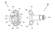
次に図3及び図4を用いて、打撃機構50を構成する第2遊星キャリヤ組立体51とアンビル61の詳細構造を説明する。図3は、第2遊星キャリヤ組立体51とアンビル61の形状を示す斜視図であり、第2遊星キャリヤ組立体51は斜め前方から、アンビル61は斜め後方から見た図である。図4は、第2遊星キャリヤ組立体51とアンビル61の形状を示す斜視図であり、第2遊星キャリヤ組立体51は斜め後方から、アンビル61は斜め前方から見た図である。第2遊星キャリヤ組立体51は、一体に構成される円盤状部材54を基本とし、円盤状部材54の対向する2箇所に軸方向前方に突出する2つのハンマ52、53が形成される。ハンマ52、53は打撃部(打撃爪)として機能し、ハンマ52の円周方向には、打撃面52aと52bが形成され、ハンマ53の円周方向には、打撃面53aと53bが形成される。打撃面52a、52b、53a、53bは、共に平面に形成されたもので、アンビル61の後述する被打撃面と良好に面接触する形成される。円盤状部材54の中心軸付近から前方に、突当部56aと嵌合軸56bが形成される。円盤状部材54の外周付近の後方側は、スラスト軸受45と当接するための円環状の当接面54aが形成される。  Next, the detailed structure of the secondplanet carrier assembly 51 and theanvil 61 constituting thestriking mechanism 50 will be described with reference to FIGS. 3 and 4. FIG. 3 is a perspective view showing the shapes of the secondplanet carrier assembly 51 and theanvil 61. The secondplanet carrier assembly 51 is viewed obliquely from the front, and theanvil 61 is viewed obliquely from the rear. FIG. 4 is a perspective view showing the shapes of the secondplanet carrier assembly 51 and theanvil 61. The secondplanet carrier assembly 51 is seen from the obliquely rear side, and theanvil 61 is seen from the obliquely front side. The secondplanetary carrier assembly 51 is based on a disk-shapedmember 54 that is integrally formed, and twohammers 52 and 53 that protrude forward in the axial direction are formed at two opposing positions of the disk-shapedmember 54.Hammers 52 and 53 function as striking portions (striking claws), striking surfaces 52 a and 52 b are formed in the circumferential direction ofhammer 52, andstriking surfaces 53 a and 53 b are formed in the circumferential direction ofhammer 53. The The striking surfaces 52a, 52b, 53a, 53b are all formed in a flat surface, and are formed in good surface contact with a striking surface to be described later of theanvil 61. Anabutting portion 56a and afitting shaft 56b are formed forward from the vicinity of the central axis of the disk-shapedmember 54. Anannular contact surface 54 a for contacting thethrust bearing 45 is formed on the rear side near the outer periphery of the disk-shapedmember 54.

円盤状部材54の後方側には遊星キャリヤの機能を有するように2つの円盤部55a、55bが形成され、円周方向の3箇所において円盤部55a、55bを接続する接続部55cが形成される。円盤部55a、55bの円周方向のそれぞれ3箇所には、貫通穴55d、55eが形成され、円盤部55a、55bの間に3つの第2プラネタリーギヤ56(図2参照)が配置され、第2プラネタリーギヤ56の回転軸たるニードルピン57(図2参照)が貫通穴55d、55eに装着される。円盤部55bの後方側中心軸付近には円形のくり貫き穴55fが形成される。くり貫き穴55fを介して第2ピニオン35が貫通し、第2プラネタリーギヤ56と噛合する。尚、第2遊星キャリヤ組立体51は、金属の一体構造にて製造すると強度的にも重量的にも好ましい。同様にアンビル61も金属の一体構造にて製造すると強度的にも重量的にも好ましい。  Twodisk portions 55a and 55b are formed on the rear side of the disk-shapedmember 54 so as to function as a planet carrier, andconnection portions 55c for connecting thedisk portions 55a and 55b are formed at three locations in the circumferential direction. . Throughholes 55d and 55e are formed at three locations in the circumferential direction of thedisk portions 55a and 55b, and three second planetary gears 56 (see FIG. 2) are disposed between thedisk portions 55a and 55b. A needle pin 57 (see FIG. 2), which is the rotation axis of the secondplanetary gear 56, is mounted in the throughholes 55d and 55e. A circular hole 55f is formed in the vicinity of the central axis on the rear side of thedisk portion 55b. Thesecond pinion 35 penetrates through the bored hole 55 f and meshes with the secondplanetary gear 56. The secondplanet carrier assembly 51 is preferable in terms of strength and weight when manufactured in a metal integrated structure. Similarly, it is preferable in terms of strength and weight to manufacture theanvil 61 with a metal integrated structure.

アンビル61は、円柱形の出力軸部分62の後方に円盤部63が形成され、この円盤部63の外周方向に突出する2つの打撃爪64、65が形成される。打撃爪64の円周方向両側には被打撃面64a及び64bが形成される。同様に打撃爪65の円周方向両側には被打撃面65a及び65bが形成される。円盤部63の中央には嵌合穴63aが形成され、嵌合軸56bが嵌合穴63aによって回動可能なように接続されることにより、第2遊星キャリヤ組立体51とアンビル61が、モータ3の回転軸4と同軸延長線上にて相対回転できるように構成される。  Theanvil 61 is formed with adisk portion 63 at the rear of the cylindricaloutput shaft portion 62, and two hittingclaws 64 and 65 protruding in the outer peripheral direction of thedisk portion 63 are formed. The hitting surfaces 64 a and 64 b are formed on both sides of the hittingclaw 64 in the circumferential direction. Similarly, hittingsurfaces 65 a and 65 b are formed on both sides of the hittingclaw 65 in the circumferential direction. Afitting hole 63a is formed in the center of thedisk portion 63, and thefitting shaft 56b is connected so as to be rotatable by thefitting hole 63a, whereby the secondplanet carrier assembly 51 and theanvil 61 are connected to each other by the motor. 3 is configured to be able to rotate relative to therotation shaft 4 on the same extension line.

第2遊星キャリヤ組立体51が正回転(ネジ等を締め付ける回転方向)するときには、打撃面52aが被打撃面64aに当接し、同時に打撃面53aが被打撃面65aに当接する。また、第2遊星キャリヤ組立体51が逆回転(ネジ等をゆるめる回転方向)するときには、打撃面52bが被打撃面65bに当接し、同時に打撃面53bが被打撃面64bに当接する。この当接するタイミングが同時となるようにハンマ52、53及び打撃爪64、65の形状が決定されるので、回転する軸心を基準に対称な2箇所にて打撃が行われるので打撃時のバランスが良く、打撃時にインパクト工具1が振られにくく構成できる。  When the secondplanet carrier assembly 51 rotates in the forward direction (rotation direction for tightening a screw or the like), thestriking surface 52a abuts on thestriking surface 64a, and at the same time, thestriking surface 53a abuts on thestriking surface 65a. Further, when the secondplanetary carrier assembly 51 rotates in the reverse direction (rotating direction for loosening screws or the like), thestriking surface 52b comes into contact with thehit surface 65b, and at the same time, thehit surface 53b comes into contact with thehit surface 64b. Since the shapes of thehammers 52 and 53 and the hittingclaws 64 and 65 are determined so that the contact timing is the same, the hitting is performed at two symmetrical positions with respect to the rotating axis, so that the balance at the time of hitting Theimpact tool 1 can be configured not to be shaken at the time of impact.

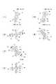
図5は、ハンマ52、53及び打撃爪64、65の使用状態における一回転の動きを6段階で示した断面図である。断面は軸方向と垂直面であって、図2のA−A部の断面である。図5においては、ハンマ52、53及び円盤部55aが一体に回転する部分(駆動側)であり、打撃爪64、65が一体に回転する部分(被駆動側)である。図5(1)の状態において、先端工具からうける締め付けトルクが小さいうちは、打撃爪64、65はハンマ52、53から押されることにより反時計回りに回転する。しかしながら、締め付けトルクが大きくなってハンマ52、53から押される力だけでは回転できなくなった場合には、ハンマ52、53を逆回転させるべく、モータ3の逆回転を開始する。(1)で示す状態においてモータ3の反転を開始し、それによって(2)に示すようにハンマ52、53を矢印58aの方向に回転させる。  FIG. 5 is a cross-sectional view showing the movement of one rotation in the use state of thehammers 52 and 53 and the hittingclaws 64 and 65 in six stages. The cross section is a plane perpendicular to the axial direction and is a cross section taken along line AA in FIG. In FIG. 5, thehammers 52, 53 and thedisk portion 55 a are a part (drive side) that rotates integrally, and thestriking claws 64, 65 are a part (drive side) that rotate integrally. In the state of FIG. 5 (1), the hittingclaws 64 and 65 are rotated counterclockwise by being pushed from thehammers 52 and 53 while the tightening torque received from the tip tool is small. However, when the tightening torque becomes large and the rotation cannot be performed only by the force pushed from thehammers 52 and 53, themotor 3 starts to rotate backward to rotate thehammers 52 and 53 backward. In the state indicated by (1), reversal of themotor 3 is started, whereby thehammers 52 and 53 are rotated in the direction of thearrow 58a as indicated by (2).

モータ3が所定回転数まで逆回転したら、モータ3の駆動を停止する。ハンマ52、53は惰性によりさらに逆回転して、矢印58bに示すように図5(3)の位置(逆回転の停止位置)に到達したら、モータ3に正回転方向への駆動電流を流すことにより、ハンマ52、53の矢印59aの方向(正回転方向)への回転を開始する。尚、ハンマ52、53を逆回転させた際に、ハンマ52と打撃爪65、及びハンマ53と打撃爪64が衝突しないように、所定位置において確実にハンマ52、53を停止させることが重要である。ハンマ52、53の停止位置を、打撃爪64、65と衝突する位置のどの程度前に設定するかは任意であるが、必要とされる締め付けトルクが大きいときは、反転角を大きくすると良い。停止位置の制御は、モータ3の回転位置検出素子の出力信号を用いて行うが、この制御の方法については後述する。  When themotor 3 reversely rotates to a predetermined rotational speed, the driving of themotor 3 is stopped. Thehammers 52 and 53 further reversely rotate due to inertia, and when the position shown in FIG. 5 (3) (reverse rotation stop position) is reached as indicated by anarrow 58b, a drive current in the forward rotation direction is supplied to themotor 3. As a result, thehammers 52 and 53 start to rotate in the direction of thearrow 59a (forward rotation direction). It is important that thehammers 52 and 53 are reliably stopped at predetermined positions so that thehammer 52 and the hittingclaws 65 and thehammer 53 and the hittingclaws 64 do not collide when thehammers 52 and 53 are reversely rotated. is there. It is arbitrary how long the stop positions of thehammers 52 and 53 are set before the positions where thehammers 52 and 53 collide with thestriking claws 64 and 65. However, when the required tightening torque is large, the reversal angle may be increased. The control of the stop position is performed using the output signal of the rotational position detection element of themotor 3, and this control method will be described later.

そして、図5(4)で示すようにハンマ52、53を矢印59bの方向に加速させて、矢印59cにように加速中の状態のまま図5(5)に示す位置にてハンマ52の打撃面52aは打撃爪64の被打撃面64aと衝突する。同時に、ハンマ53の打撃面53aは打撃爪65の被打撃面65aと衝突する。この衝突の結果、打撃爪64、65には強力な回転トルクが伝達され、打撃爪64、65は矢印59dで示す方向に回転する。図5(6)の位置は、図5(1)で示した状態から、ハンマ52、53と打撃爪64、65の双方が所定角度分だけ回転した状態であり、再び図5(1)の状態から図5(5)に至る正転及び逆転動作を繰り返すことによって、被締め付け部材を適正トルクになるまで締め付けを行う。  Then, thehammers 52 and 53 are accelerated in the direction of thearrow 59b as shown in FIG. 5 (4), and thehammer 52 is struck at the position shown in FIG. 5 (5) while being accelerated as shown by thearrow 59c. Thesurface 52 a collides with thehit surface 64 a of the hittingclaw 64. At the same time, thestriking surface 53 a of thehammer 53 collides with thestriking surface 65 a of thestriking claw 65. As a result of this collision, a strong rotational torque is transmitted to the hittingclaws 64 and 65, and the hittingclaws 64 and 65 rotate in the direction indicated by thearrow 59d. The position shown in FIG. 5 (6) is a state where both thehammers 52 and 53 and the hittingclaws 64 and 65 are rotated by a predetermined angle from the state shown in FIG. 5 (1). By repeating the normal rotation and reverse rotation operation from the state to FIG. 5 (5), the member to be tightened is tightened until the proper torque is obtained.

次に、モータ3の駆動制御系の構成と作用を図6に基づいて説明する。図6はモータ3の駆動制御系の構成を示すブロック図であり、本実施例では、モータ3は3相のブラシレスDCモータで構成される。このブラシレスDCモータは、いわゆるインナーロータ型であって、複数組(本実施例では2組)のN極とS極を含む永久磁石(マグネット)を含んで構成される回転子(ロータ)3aと、スター結線された3相の固定子巻線U、V、Wから成る固定子3bと、回転子3aの回転位置を検出するために周方向に所定の間隔毎、例えば角度60°毎に配置された3つの回転位置検出素子(ホール素子)78を有する。これら回転位置検出素子78からの位置検出信号に基づいて固定子巻線U、V、Wへの通電方向と時間が制御され、モータ3が回転する。  Next, the configuration and operation of the drive control system of themotor 3 will be described with reference to FIG. FIG. 6 is a block diagram showing the configuration of the drive control system of themotor 3. In this embodiment, themotor 3 is a three-phase brushless DC motor. This brushless DC motor is a so-called inner rotor type, and includes a rotor (rotor) 3a including a plurality of sets (two sets in this embodiment) of permanent magnets (magnets) including N poles and S poles. In order to detect the rotational position of therotor 3a, astator 3b composed of three-phase stator windings U, V, and W connected in a star connection is arranged at predetermined intervals in the circumferential direction, for example, at an angle of 60 °. The three rotational position detecting elements (Hall elements) 78 are provided. Based on the position detection signals from these rotationalposition detection elements 78, the energization direction and time for the stator windings U, V, W are controlled, and themotor 3 rotates.

インバータ基板10上に搭載される電子素子には、3相ブリッジ形式に接続されたFETなどの6個のスイッチング素子Q1〜Q6を含む。ブリッジ接続された6個のスイッチング素子Q1〜Q6の各ゲートは、制御回路基板9に搭載される制御信号出力回路73に接続され、6個のスイッチング素子Q1〜Q6の各ドレインまたは各ソースは、スター結線された固定子巻線U、V、Wに接続される。これによって、6個のスイッチング素子Q1〜Q6は、制御信号出力回路73から入力されたスイッチング素子駆動信号(H4、H5、H6等の駆動信号)によってスイッチング動作を行い、インバータ回路72に印加されるバッテリパック2の直流電圧を3相(U相、V相及びW相)電圧Vu、Vv、Vwとして固定子巻線U、V、Wに電力を供給する。  The electronic elements mounted on theinverter substrate 10 include six switching elements Q1 to Q6 such as FETs connected in a three-phase bridge format. The gates of the six switching elements Q1 to Q6 connected in a bridge are connected to a controlsignal output circuit 73 mounted on the control circuit board 9, and the drains or sources of the six switching elements Q1 to Q6 are It is connected to the stator windings U, V, W that are star-connected. As a result, the six switching elements Q1 to Q6 perform a switching operation by the switching element drive signals (drive signals such as H4, H5, and H6) input from the controlsignal output circuit 73 and are applied to theinverter circuit 72. Electric power is supplied to the stator windings U, V, and W with the DC voltage of thebattery pack 2 as three-phase (U-phase, V-phase, and W-phase) voltages Vu, Vv, and Vw.

6個のスイッチング素子Q1〜Q6の各ゲートを駆動するスイッチング素子駆動信号(3相信号)のうち、3個の負電源側スイッチング素子Q4、Q5、Q6をパルス幅変調信号(PWM信号)H4、H5、H6として供給し、制御回路基板9上に搭載された演算部71によって、トリガスイッチ8のトリガ操作部8aの操作量(ストローク)の検出信号に基づいてPWM信号のパルス幅(デューティ比)を変化させることによってモータ3への電力供給量を調整し、モータ3の起動/停止と回転速度を制御する。  Of the switching element drive signals (three-phase signals) for driving the gates of the six switching elements Q1 to Q6, the three negative power supply side switching elements Q4, Q5, Q6 are converted into pulse width modulation signals (PWM signals) H4, The pulse width (duty ratio) of the PWM signal is supplied as H5 and H6 and based on the detection signal of the operation amount (stroke) of thetrigger operation unit 8a of thetrigger switch 8 by thearithmetic unit 71 mounted on the control circuit board 9. The amount of electric power supplied to themotor 3 is adjusted by changing, and the start / stop of themotor 3 and the rotation speed are controlled.

ここで、PWM信号は、インバータ回路72の正電源側スイッチング素子Q1〜Q3または負電源側スイッチング素子Q4〜Q6の何れか一方に供給され、スイッチング素子Q1〜Q3またはスイッチング素子Q4〜Q6を高速スイッチングさせることによってバッテリパック2の直流電圧から各固定子巻線U、V、Wに供給する電力を制御する。尚、本実施例では、負電源側スイッチング素子Q4〜Q6にPWM信号が供給されるため、PWM信号のパルス幅を制御することによって各固定子巻線U、V、Wに供給する電力を調整してモータ3の回転速度を制御することができる。  Here, the PWM signal is supplied to any one of the positive power supply side switching elements Q1 to Q3 or the negative power supply side switching elements Q4 to Q6 of theinverter circuit 72, and the switching elements Q1 to Q3 or the switching elements Q4 to Q6 are switched at high speed. As a result, the power supplied to the stator windings U, V, W from the DC voltage of thebattery pack 2 is controlled. In this embodiment, since the PWM signal is supplied to the negative power supply side switching elements Q4 to Q6, the power supplied to each stator winding U, V, W is adjusted by controlling the pulse width of the PWM signal. Thus, the rotation speed of themotor 3 can be controlled.

インパクト工具1には、モータ3の回転方向を切り替えるための正逆切替レバー14が設けられ、回転方向設定回路82は正逆切替レバー14の変化を検出するごとに、モータの回転方向を切り替えて、その制御信号を演算部71に送信する。演算部71は、図示していないが、処理プログラムとデータに基づいて駆動信号を出力するための中央処理装置(CPU)、処理プログラムや制御データを記憶するためのROM、データを一時記憶するためのRAM、タイマ等を含んで構成される。  Theimpact tool 1 is provided with a forward /reverse switching lever 14 for switching the rotational direction of themotor 3, and the rotationaldirection setting circuit 82 switches the rotational direction of the motor each time a change in the forward /reverse switching lever 14 is detected. The control signal is transmitted to thecalculation unit 71. Although not shown, thecalculation unit 71 is a central processing unit (CPU) for outputting a drive signal based on the processing program and data, a ROM for storing the processing program and control data, and for temporarily storing data. RAM, a timer, and the like.

制御信号出力回路73は、回転方向設定回路82と回転子位置検出回路74の出力信号に基づいて所定のスイッチング素子Q1〜Q6を交互にスイッチングするための駆動信号を形成し、その駆動信号を制御信号出力回路73に出力する。これによって固定子巻線U、V、Wの所定の巻線に交互に通電し、回転子3aを設定された回転方向に回転させる。この場合、負電源側スイッチング素子Q4〜Q6に印加する駆動信号は、印加電圧設定回路81の出力制御信号に基づいてPWM変調信号として出力される。モータ3に供給される電流値は、電流検出回路79によって測定され、その値が演算部71にフィードバックされることにより、設定された駆動電力となるように調整される。尚、PWM信号は正電源側スイッチング素子Q1〜Q3に印加しても良い。  The controlsignal output circuit 73 forms a drive signal for alternately switching predetermined switching elements Q1 to Q6 based on the output signals of the rotationdirection setting circuit 82 and the rotorposition detection circuit 74, and controls the drive signal. The signal is output to thesignal output circuit 73. As a result, the predetermined windings of the stator windings U, V, and W are alternately energized to rotate therotor 3a in the set rotation direction. In this case, the drive signal applied to the negative power supply side switchingelements Q 4 toQ 6 is output as a PWM modulation signal based on the output control signal of the appliedvoltage setting circuit 81. The current value supplied to themotor 3 is measured by thecurrent detection circuit 79, and the value is fed back to thecalculation unit 71 to be adjusted to the set drive power. The PWM signal may be applied to the positive power supply side switching elements Q1 to Q3.

次に、本実施例に係るインパクト工具1の駆動方法について説明する。本実施例に係るインパクト工具1においては、アンビル61とハンマ52、53が、相対的に180度未満の回転角で回転可能なように形成される。従って、ハンマ52、53はアンビル61に対して半回転以上の相対回転ができないため、その回転制御も特有のものになる。  Next, a driving method of theimpact tool 1 according to the present embodiment will be described. In theimpact tool 1 according to the present embodiment, theanvil 61 and thehammers 52 and 53 are formed so as to be relatively rotatable at a rotation angle of less than 180 degrees. Therefore, thehammers 52 and 53 cannot rotate relative to theanvil 61 by more than a half rotation, so that the rotation control is also unique.

本実施例に係るインパクト工具1において、インパクトモードにおける締め付け作業の場合は、最初“連続駆動モード”で高速に締め付けを行い、必要な締め付けトルク値が大きくなったら“断続駆動モード”に切り替えて締め付けを行う。“連続駆動モード”では、演算部71はモータ3を目標回転数に基づく制御を行う。このためモータ3は目標回転数に達するまで加速し、アンビル61は、ハンマ52、53に押されながら回転する。その後、アンビル61に取り付けられた先端工具からの締め付け反力が大きくなると、アンビル61からハンマ52、53に伝わる反力が大きくなるため、モータ3の回転速度が徐々に落ちてくる。そこで、その回転速度の落ち込みを検出して、モータを反転させる“断続駆動モード”を開始する。  In theimpact tool 1 according to the present embodiment, in the case of tightening work in the impact mode, first, fast tightening is performed in the “continuous drive mode”, and when the necessary tightening torque value becomes large, the switching is performed to the “intermittent drive mode”. I do. In the “continuous drive mode”, thecalculation unit 71 controls themotor 3 based on the target rotational speed. For this reason, themotor 3 is accelerated until the target rotational speed is reached, and theanvil 61 rotates while being pushed by thehammers 52 and 53. Thereafter, when the tightening reaction force from the tip tool attached to theanvil 61 is increased, the reaction force transmitted from theanvil 61 to thehammers 52 and 53 is increased, so that the rotational speed of themotor 3 gradually decreases. Therefore, a drop in the rotational speed is detected, and an “intermittent drive mode” for inverting the motor is started.

断続駆動モードは、モータ3を連続的に駆動するのではなく断続的に駆動するモードであり、「正回転駆動と逆回転駆動」を複数回繰り返すようにモータ3をパルス状に駆動する。ここで、本明細書における「パルス状に駆動する」とは、インバータ回路72に加えるゲート信号を脈動させることにより、モータ3に供給される駆動電流を脈動させ、それによってモータ3の回転数又は出力トルクを脈動させるように駆動制御することである。脈動の周期は、例えば数十Hz〜百数十Hz程度である。正回転駆動と逆回転駆動の切り替えの間には、休止時間を介するようにしても良いし、休止時間無しで切り替えるようにしても良い。尚、駆動電流ON状態の時にはモータ3の回転数制御のためにPWM制御が行われるが、そのデューティ比制御の周期(通常数キロHz)に比べると、脈動させる周期は十分小さい。  The intermittent drive mode is a mode in which themotor 3 is driven intermittently rather than continuously, and themotor 3 is driven in pulses so that “forward rotation drive and reverse rotation drive” are repeated a plurality of times. Here, “driven in the form of pulses” in this specification means that the drive current supplied to themotor 3 is pulsated by pulsating the gate signal applied to theinverter circuit 72, and thereby the rotational speed of themotor 3 or Driving control is performed so as to pulsate the output torque. The cycle of pulsation is, for example, about several tens Hz to several tens Hz. Between the forward rotation drive and the reverse rotation drive, a pause time may be used or may be switched without the pause time. Note that PWM control is performed to control the rotational speed of themotor 3 when the drive current is ON, but the pulsation cycle is sufficiently small compared to the duty ratio control cycle (usually several kilohertz).

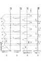
図7は本発明のインパクト工具を“断続駆動モード”で動作させる際のモータ制御について説明するための図であって、(1)〜(4)の4つのグラフの横軸は経過する時間t(秒)であって、それぞれのグラフの横軸を合わせて図示している。断続駆動モードでは、ハンマ52、53をアンビル61に対して十分な相対角だけ逆回転させた後に正回転方向に加速させて、勢いよくアンビル61に衝突させる。このようにハンマ52、53を逆回転方向及び正回転方向に駆動することにより、アンビル61に強い締め付けトルクを発生させるものである。  FIG. 7 is a diagram for explaining motor control when the impact tool of the present invention is operated in the “intermittent drive mode”, and the horizontal axis of the four graphs (1) to (4) indicates the elapsed time t. (Seconds) and the horizontal axes of the respective graphs are shown together. In the intermittent drive mode, thehammers 52 and 53 are reversely rotated by a sufficient relative angle with respect to theanvil 61 and then accelerated in the forward rotation direction so as to collide with theanvil 61 vigorously. By driving thehammers 52 and 53 in the reverse rotation direction and the normal rotation direction in this way, a strong tightening torque is generated in theanvil 61.

図7(1)は、ハンマ52、53の回転角、つまり第2遊星キャリヤ組立体51の回転角を示すグラフである。縦軸はハンマ52、53の回転角(単位rad)である。時間0においてインパクト工具1の回転を開始すると、時間0〜t1までは“連続駆動モード”で回転させる。演算部71は“連続駆動モード”で回転中のハンマ52、53の回転角の変化率(=Δθ/Δt)を周期的に求めて、その変化率を監視する。ハンマ52、53の回転角は、回転位置検出素子78の出力信号から回転子位置検出回路74が所定間隔毎の検出パルスを演算部71に出力するので、演算部71はこの検出パルス数を監視することにより回転角の変化率を算出できる。本実施例においては、ホールIC等の回転子位置検出回路74が回転角で60度ずつ隔てて3つ設けられているので、回転子位置検出回路74から出力される検出パルスは、回転子3aの回転角にして60度毎に出力される。本実施例では回転子3aの回転は遊星歯車減速機構20にて所定の減速比(本実施例では1:15)で減速される。減速比が1:15とすると、ハンマ52、53の回転角にして4度毎に回転位置検出素子78の検出パルスが出力されることになる。従って、“断続駆動モード”において、回転子位置検出回路74の検出パルスをカウントすることによって、演算部71はハンマ52、53のアンビル61に対する相対的な回転角を検出することができる。  FIG. 7 (1) is a graph showing the rotation angle of thehammers 52, 53, that is, the rotation angle of the secondplanet carrier assembly 51. The vertical axis represents the rotation angle (unit: rad) of thehammers 52 and 53. When theimpact tool 1 starts rotating at time 0, it is rotated in the “continuous drive mode” from time 0 to t1. Thecalculation unit 71 periodically obtains the rate of change (= Δθ / Δt) of the rotation angle of the rotatinghammers 52 and 53 in the “continuous drive mode” and monitors the rate of change. As for the rotation angle of thehammers 52 and 53, the rotorposition detection circuit 74 outputs detection pulses at predetermined intervals to thecalculation unit 71 from the output signal of the rotationposition detection element 78, so thecalculation unit 71 monitors the number of detection pulses. By doing so, the rate of change of the rotation angle can be calculated. In this embodiment, since three rotorposition detection circuits 74 such as Hall ICs are provided 60 degrees apart at a rotation angle, the detection pulse output from the rotorposition detection circuit 74 is therotor 3a. Are output every 60 degrees. In this embodiment, the rotation of therotor 3a is reduced by the planetarygear reduction mechanism 20 at a predetermined reduction ratio (1:15 in this embodiment). If the reduction ratio is 1:15, detection pulses of the rotationalposition detecting element 78 are output every 4 degrees for the rotation angles of thehammers 52 and 53. Therefore, in the “intermittent drive mode”, thecalculation unit 71 can detect the relative rotation angle of thehammers 52 and 53 with respect to theanvil 61 by counting the detection pulses of the rotorposition detection circuit 74.

図7(1)の時間t1において、締め付け対象たるボルト等が着座し、ハンマ52、53の回転角の変化率が大きく減少する。この際、僅かながらハンマに打撃トルク111が発生する。演算部71は、時間t1〜t2において回転角変化率が所定の閾値よりも小さくなったことを検出したら、モータ3に供給する正転駆動電圧121を停止し、時間t2において逆転駆動電圧122の供給を開始する。逆転駆動電圧122は、演算部71(図6参照)が負の方向の駆動信号を制御信号出力回路73(図6参照)に送ることにより行われる。モータ3の正転、逆転を行う際には、制御信号出力回路73から各スイッチング素子Q1〜Q6に出力する各駆動信号(オンオフ信号)の信号パターンを切り替えることにより実現される。尚、インバータ回路72を用いたモータ3の回転駆動においては、印加電圧をプラスからマイナスに切り替えるものではなく、駆動電圧を供給するコイルへの供給順序を変えるだけであるが、図7(3)でどちら方向へ回転駆動するかを容易に理解できるように、正逆印加電圧を+及び−に分けて模式的に表現した。  At time t1 in FIG. 7 (1), a bolt or the like to be tightened is seated, and the change rate of the rotation angle of thehammers 52 and 53 is greatly reduced. At this time, a slight impact torque 111 is generated on the hammer. When thecalculation unit 71 detects that the rotation angle change rate has become smaller than a predetermined threshold value at the time t1 to t2, thecalculation unit 71 stops the normalrotation drive voltage 121 supplied to themotor 3, and the reverserotation drive voltage 122 at the time t2. Start supplying. Thereverse drive voltage 122 is performed by the calculation unit 71 (see FIG. 6) sending a negative drive signal to the control signal output circuit 73 (see FIG. 6). When themotor 3 is rotated forward or backward, it is realized by switching the signal pattern of each drive signal (on / off signal) output from the controlsignal output circuit 73 to each switching element Q1 to Q6. In the rotational drive of themotor 3 using theinverter circuit 72, the applied voltage is not switched from positive to negative, but only the supply sequence to the coil that supplies the drive voltage is changed. Thus, the forward and reverse applied voltages are schematically expressed by dividing them into + and − so that it can be easily understood in which direction the rotation is driven.

逆転駆動電圧122の供給によって、モータ3は逆回転を開始し、それによってハンマ52、53も逆回転を開始する(矢印102)。この逆回転時には、ハンマ52、53はアンビル61の打撃爪64、65から離れる方向への移動なので無負荷状態での回転となり、ハンマ52、53が大きく逆転する。次に、時間t3においてハンマ52、53の回転角の減少量が所定の閾値cに到達したら、モータ3に正転駆動電圧123の供給を開始する。正転駆動電圧123の供給によって、モータ3は再び正回転を開始し、それによってハンマ52、53も正回転を開始する。この正回転時には、ハンマ52、53はアンビル61の打撃爪64、65に再び接近方向への移動なので、無負荷状態となりハンマ52、53の回転角が大きく増加する(矢印103)。  By supplying thereverse drive voltage 122, themotor 3 starts reverse rotation, and thehammers 52 and 53 also start reverse rotation (arrow 102). At the time of this reverse rotation, thehammers 52 and 53 move away from the hittingclaws 64 and 65 of theanvil 61, so that thehammers 52 and 53 are largely reversed. Next, when the amount of decrease in the rotation angle of thehammers 52 and 53 reaches a predetermined threshold value c at time t3, supply of the normalrotation drive voltage 123 to themotor 3 is started. By supplying the normalrotation driving voltage 123, themotor 3 starts to rotate forward again, and thehammers 52 and 53 also start to rotate forward. At the time of this forward rotation, thehammers 52 and 53 move again in the approaching direction to thestriking claws 64 and 65 of theanvil 61, so that no load is applied and the rotation angles of thehammers 52 and 53 are greatly increased (arrow 103).

次に、時間t4においてハンマ52、53の回転角の増加量が閾値cに到達したら、モータ3への正転駆動電圧123の供給を停止させる。この停止させる際が、モータ3の回転速度が最大速度に達する付近であり、ハンマ52、53は勢いよく打撃爪64、65に衝突し、この衝突により打撃トルク111に比べて大きい打撃トルク112が発生する。理想的には閾値cに到達した地点t4においてハンマ52、53がアンビル61の打撃爪64、65に衝突する。このようにハンマ52、53がアンビル61を打撃するタイミング近傍でモータ3の正転駆動を停止させるようにしたので、打撃の際にはハンマ52、53(第2遊星キャリヤ組立体51)は惰性で回転し、第2遊星キャリヤ組立体51の慣性のみでハンマ52、53はアンビル61に対する打撃を行うことができる。この結果、モータ3への過剰な電流供給を抑制することができ、効率的なインパクト動作を実現できる。尚、「打撃の際」とは、打撃の時と一致している場合だけでなく、打撃のほんの僅か前であってもほんの僅かだけ後であっても良い。打撃前におけるハンマ52、53に対するアンビル61の位置は、専用の位置センサで正確に検出している訳ではないので、厳密な制御をするのは難しいが、少なくとも打撃トルクが発生している期間内(t4〜t5)のほとんどの区間でモータ3への正転駆動電圧123の供給が停止されるような状態とすれば良い。  Next, when the increase amount of the rotation angle of thehammers 52 and 53 reaches the threshold value c at time t4, the supply of the normalrotation drive voltage 123 to themotor 3 is stopped. When stopping, the rotation speed of themotor 3 reaches the maximum speed, and thehammers 52 and 53 vigorously collide with thestriking claws 64 and 65, and the impact torque 112 larger than the striking torque 111 is caused by this collision. Occur. Ideally, thehammers 52 and 53 collide with the hittingclaws 64 and 65 of theanvil 61 at the point t4 when the threshold value c is reached. As described above, since the forward rotation of themotor 3 is stopped in the vicinity of the timing when thehammers 52 and 53 strike theanvil 61, thehammers 52 and 53 (second planetary carrier assembly 51) are inertial at the time of impact. Thehammers 52 and 53 can hit theanvil 61 only by the inertia of the secondplanet carrier assembly 51. As a result, an excessive current supply to themotor 3 can be suppressed, and an efficient impact operation can be realized. The “when hitting” is not limited to the case of hitting, but may be just before the hit or just after the hit. The position of theanvil 61 with respect to thehammers 52 and 53 before hitting is not accurately detected by a dedicated position sensor, so it is difficult to perform precise control, but at least within the period during which hitting torque is generated What is necessary is just to set it as the state where supply of the normalrotation drive voltage 123 to themotor 3 is stopped in the most area of (t4-t5).

時間t4にて打撃が行われると、打撃トルクが消失する時間t5において、モータ3に逆転駆動電圧124の供給を開始し、ハンマ52、53の逆回転を開始させる(矢印104)。ハンマ52、53が閾値cだけ逆回転したら、モータ3の駆動電圧を正転駆動電圧125に切り替える。正転駆動電圧125の供給によって、モータ3を再び正回転させ(矢印105)、時間t7においてハンマ52、53の回転角の増加量が閾値cに到達したら、モータ3に正転駆動電圧125の供給を停止させる。この停止とほぼ同時にハンマ52、53がアンビル61の打撃爪64、65に衝突するので、以降は時間t4〜t7と同じ制御を繰り返し、モータ3の逆転駆動電圧126、128の供給、正転駆動電圧127、129の供給、モータ3への駆動電圧の停止(時間t10、t13)を繰り返すことによってインパクト動作を行い、ボルト等の締め付け部材の締め付けを完了させる。締め付け作業の終了は、時間t15にて作業者がトリガスイッチ8を離すことによって行う。尚、作業の終了は作業者がトリガスイッチ8を離すだけでなく、アンビル61による締め付けトルク値を検出する公知のセンサ(図示せず)を付加し、締め付けトルク値が所定の値になったときに演算部71がモータ3への駆動電圧を強制的に停止させるように構成しても良い。  When an impact is made at time t4, at time t5 when the impact torque disappears, supply of the reverse drive voltage 124 to themotor 3 is started, and reverse rotation of thehammers 52 and 53 is started (arrow 104). When thehammers 52 and 53 rotate backward by the threshold value c, the drive voltage of themotor 3 is switched to the normalrotation drive voltage 125. When the forwardrotation drive voltage 125 is supplied, themotor 3 is rotated forward again (arrow 105). When the amount of increase in the rotation angle of thehammers 52 and 53 reaches the threshold value c at time t7, the forwardrotation drive voltage 125 is supplied to themotor 3. Stop supplying. Since thehammers 52 and 53 collide with thestriking claws 64 and 65 of theanvil 61 almost simultaneously with this stop, the same control is repeated from time t4 to t7 to supply thereverse drive voltages 126 and 128 of themotor 3 and forward drive. The impact operation is performed by repeating the supply of the voltages 127 and 129 and the stop of the drive voltage to the motor 3 (time t10 and t13), and the tightening of the tightening member such as a bolt is completed. The tightening operation is completed when the operator releases thetrigger switch 8 at time t15. In addition, when the operator ends not only thetrigger switch 8 but also a known sensor (not shown) for detecting the tightening torque value by theanvil 61 is added, the tightening torque value becomes a predetermined value. Alternatively, thecalculation unit 71 may be configured to forcibly stop the drive voltage to themotor 3.

図7(4)は、モータ3に流れる電流の大きさを示すグラフである。正転駆動電圧121、123、‥を供給した直後、及び、逆転駆動電圧122、124、‥を供給した直後の始動電流に相当する部分の電流値が大きくなっているのが理解できるであろう。  FIG. 7 (4) is a graph showing the magnitude of the current flowing through themotor 3. It can be understood that the current value of the portion corresponding to the starting current immediately after supplying the forward rotation drivevoltages 121, 123,... And immediately after supplying thereverse drive voltages 122, 124,. .

本実施例においては締め付けトルクが少なくてすむ締め付け初期段階は連続駆動モードで回転駆動し、必要な締め付けトルクが大きくなったら断続駆動モードを用いてネジやボルト等の締め付けを行う。また、逆転及び正転させるハンマの回転角を、回転位置検出素子の出力に基づいて得られる回転角度によって精密に制御するにしたので、効率が良く消費電力の無駄が少ないインパクト工具を実現できる。また、ハンマ52、53がアンビル61を打撃するタイミング近傍でモータ3への駆動電圧の供給を停止させ、ハンマの慣性エネルギーのみでアンビルを打撃するので、効率的に打撃を行うことができる。さらに、締め付け対象がボルトやナット等の場合は打撃後に作業者の手に伝わる反動が少なくて済むという効果がある。  In this embodiment, the initial stage of tightening, which requires less tightening torque, is rotationally driven in the continuous drive mode, and when the necessary tightening torque increases, the intermittent drive mode is used to tighten screws and bolts. Further, since the rotation angle of the hammer to be rotated in the reverse direction and the forward rotation is precisely controlled by the rotation angle obtained based on the output of the rotation position detecting element, an impact tool with high efficiency and low waste of power consumption can be realized. Further, the supply of the drive voltage to themotor 3 is stopped in the vicinity of the timing at which thehammers 52 and 53 strike theanvil 61 and the anvil is struck only by the inertia energy of the hammer, so that the hammer can be efficiently struck. Furthermore, when the tightening target is a bolt, a nut, or the like, there is an effect that less reaction is transmitted to the operator's hand after hitting.

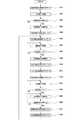
次に図8のフローチャートを用いて演算部71によるモータ3の回転制御手順を説明する。フローチャートに示す回転制御手順は、トリガスイッチ8が引かれたことを契機に開始する。また、これらの回転制御手順は演算部71に含まれる図示しないマイクロコンピュータによってプログラムを実行することによりソフトウェア的に実現できる。  Next, the rotation control procedure of themotor 3 by thecalculation unit 71 will be described using the flowchart of FIG. The rotation control procedure shown in the flowchart starts when thetrigger switch 8 is pulled. Further, these rotation control procedures can be realized by software by executing a program by a microcomputer (not shown) included in thecalculation unit 71.

トリガスイッチ8が引かれると、演算部71はハンマ52、53の回転角変化率(=Δθ/Δt)の算出を開始すると同時に、モータ3に正転電圧を印加する(ステップ201、202)。これによってモータ3は正回転を開始し、ハンマ52、53とアンビル61が一体的に回転し、ボルト等の締め付け対象の締め付けを開始する。締め付け対象が被締め付け部材に着座すると、その負荷の増加に伴い回転角変化率は、図7(1)の時間t1〜t2の部分のように大きく低下する。そこで、演算部71は短い周期で算出している回転角変化率が、予め設定された閾値aより小さくなったか否かを判定し(ステップ203)、小さくなった場合はモータ3への正転電圧印加を停止し(ステップ204)、回転角変化率算出値のリセットを行う(ステップ205)。ステップ203において回転角変化率が閾値a以上の場合は、ステップ202に戻る。  When thetrigger switch 8 is pulled, thecalculation unit 71 starts calculating the rotation angle change rate (= Δθ / Δt) of thehammers 52 and 53 and simultaneously applies a normal rotation voltage to the motor 3 (steps 201 and 202). As a result, themotor 3 starts to rotate forward, and thehammers 52 and 53 and theanvil 61 rotate together to start tightening a tightening target such as a bolt. When the object to be tightened is seated on the member to be tightened, the rate of rotation angle change greatly decreases as the load increases, as in the time t1 to t2 portion of FIG. Therefore, thecalculation unit 71 determines whether or not the rotation angle change rate calculated in a short cycle is smaller than a preset threshold value a (step 203). The voltage application is stopped (step 204), and the rotation angle change rate calculated value is reset (step 205). If the rotation angle change rate is greater than or equal to the threshold value a instep 203, the process returns to step 202.

続いて、次なる打撃動作に向け、ハンマ52、53を逆転させる(図7(1)の時間t2〜t3)。この際、ハンマ52、53の逆転方向の回転角度の算出を開始する(ステップ206、207)。次に、回転角変化率が、予め設定された閾値cより小さくなったか否かを判定し(ステップ208)、大きくなった場合は逆転電圧印加を停止する(ステップ208、209)。ここで、閾値cはハンマ52、53とアンビル61とを十分な回転角だけ引き離すために設定されるものであって、逆回転方向に打撃しない程度に十分な角度分を閾値cとして設定する。また、逆回転させる回転角によって打撃前の助走区間を調整できるので、必要とされる打撃トルクの大きさに合わせて閾値cを設定すれば良い。  Subsequently, thehammers 52 and 53 are reversed for the next striking operation (time t2 to t3 in FIG. 7A). At this time, calculation of the rotation angle of thehammers 52 and 53 in the reverse direction is started (steps 206 and 207). Next, it is determined whether or not the rotation angle change rate has become smaller than a preset threshold value c (step 208), and when it has become larger, the reverse voltage application is stopped (steps 208 and 209). Here, the threshold value c is set in order to separate thehammers 52 and 53 and theanvil 61 by a sufficient rotation angle, and the threshold value c is set to a sufficient angle so as not to strike in the reverse rotation direction. Moreover, since the run-up section before hitting can be adjusted by the rotation angle for reverse rotation, the threshold value c may be set in accordance with the magnitude of the required hitting torque.

続いて、逆回転方向の回転角度算出値をリセットし(ステップ210)、ハンマ52、53の正回転方向の回転角度の算出と回転角変化率の算出を開始し(ステップ211、212)、正転電圧を印加する(ステップ213)。正転電圧の印加開始によってモータ3が正回転方向に開始するので、ハンマ52、53はアンビル61の打撃爪64、65に接近して行くことになる。ここで、図9を用いて、ステップ208及びステップ214における反転電圧及び正転電圧の供給タイミングの決定方法について説明する。  Subsequently, the rotation angle calculation value in the reverse rotation direction is reset (step 210), the calculation of the rotation angle of thehammers 52 and 53 in the normal rotation direction and the calculation of the rotation angle change rate are started (steps 211 and 212). A commutation voltage is applied (step 213). Since themotor 3 starts in the forward rotation direction when the application of the forward rotation voltage starts, thehammers 52 and 53 approach thestriking claws 64 and 65 of theanvil 61. Here, the determination method of the supply timing of the inversion voltage and the normal rotation voltage instep 208 and step 214 will be described with reference to FIG.

図9は、モータ3の制御に用いられる回転子位置検出回路74の出力たる検出パルスの波形と、モータ3への印加電圧の供給状態を示す図である。図9(1)と(2)のグラフの横軸は時間tであり、両者の横軸は同じタイミングとなるように合わせて図示している。本実施例のモータ3に用いられるホールIC(回転位置検出素子78)は、回転角にして60度ずつ離れて配置される。この場合、回転子位置検出回路74の検出パルスはモータ3の回転子3aが60度回転する毎にパルス301、302、・・・が出現する。遊星歯車減速機構20の減速比が1:15であると、回転子3aの60度の回転はハンマ52、53の回転角4度に相当する。  FIG. 9 is a diagram illustrating a waveform of a detection pulse output from the rotorposition detection circuit 74 used for controlling themotor 3 and a supply state of an applied voltage to themotor 3. The horizontal axes of the graphs of FIGS. 9 (1) and 9 (2) are time t, and the horizontal axes of both are shown in the same timing. The Hall IC (rotational position detecting element 78) used in themotor 3 of the present embodiment is arranged 60 degrees apart from the rotation angle. In this case, the detection pulses of the rotorposition detection circuit 74 appear aspulses 301, 302,... Each time therotor 3a of themotor 3 rotates 60 degrees. When the reduction ratio of the planetarygear reduction mechanism 20 is 1:15, the rotation of therotor 3a by 60 degrees corresponds to the rotation angle of thehammers 52 and 53 by 4 degrees.

そこで、本実施例においてハンマ52、53の回転角度の閾値cを約24度とする場合は、図(2)に示すように、パルス301〜306の6パルス分が発生する間だけ逆転電圧315を供給し、その後にパルス307〜312の6パルス分だけ正転電圧316を供給するように制御する。このように、モータ3に用いられる回転位置検出素子78の検出パルスを検出することで、演算部71はハンマ52、53の回転角度が閾値cに到達したか否かを容易に判定することができる。尚、図9の例では、回転角度の閾値cを約24度としたが、閾値cの値は任意に設定することができ、図3、4に示すハンマ形状の場合は、閾値cを最大で約120度程度にまで設定可能である。閾値cを120度とした場合は、パルスが40パルス分出現する間だけモータ3を逆転させて、その後に40パルス分出現する間だけモータ3を正転させるようにすれば良い。このパルス301〜312等の出現は演算部71によって常に監視されるので、演算部71のマイクロコンピュータによってハンマ52、53の反転角度及び正転角度を容易に制御することができる。
Therefore, in the present embodiment, when the rotation angle threshold c of thehammers 52 and 53 is set to about 24 degrees, as shown in FIG.9 (2), the reverse voltage is applied only while sixpulses 301 to 306 are generated. 315 is supplied, and thereafter, the forward rotation voltage 316 is controlled to be supplied for sixpulses 307 to 312. Thus, by detecting the detection pulse of the rotationalposition detection element 78 used in themotor 3, thecalculation unit 71 can easily determine whether or not the rotation angle of thehammers 52 and 53 has reached the threshold value c. it can. In the example of FIG. 9, the threshold value c of the rotation angle is about 24 degrees, but the value of the threshold value c can be arbitrarily set. In the case of the hammer shape shown in FIGS. Can be set to about 120 degrees. When the threshold value c is 120 degrees, themotor 3 may be reversed only while 40 pulses appear, and then themotor 3 is rotated forward only when 40 pulses appear thereafter. Since the appearance of thepulses 301 to 312 and the like is constantly monitored by thecalculation unit 71, the inversion angle and the normal rotation angle of thehammers 52 and 53 can be easily controlled by the microcomputer of thecalculation unit 71.

再び図8に戻り、ステップ213において正転電圧を供給した後に、正転角度が閾値cを越えた場合は、正転電圧の供給を停止させる(ステップ215)。この停止させるタイミングとほぼ同じに、ハンマ52、53は加速度をもってアンビル61に衝突し、正転方向に強い打撃トルクが発生する(図7(1)のt4)。その後、ハンマ52、53が持つ慣性力にしたがってアンビル61と一体的に回転する(図7(1)のt4〜t5)。  Returning to FIG. 8 again, after the normal rotation voltage is supplied instep 213, if the normal rotation angle exceeds the threshold value c, the supply of the normal rotation voltage is stopped (step 215). Thehammers 52 and 53 collide with theanvil 61 with acceleration and generate a strong striking torque in the normal rotation direction (t4 in FIG. 7 (1)). Then, it rotates integrally with theanvil 61 according to the inertial force of thehammers 52 and 53 (t4 to t5 in FIG. 7 (1)).

次に、ハンマ52、53の慣性力による打撃の終了(回転の終了)を検出するために、回転角変化率が閾値aより小さくなったか否かを判定し(ステップ216)、回転角変化率が閾値a以上の場合はステップ215に戻る。回転角変化率が閾値aより小さくなった場合は、回転角変化率算出値及び相対回転角度算出値のリセットを行い(ステップ217、218)、次なる打撃動作に向けステップ206に戻る。以上の動作を、作業者がトリガスイッチ8を離すまで繰り返すことによって、ボルト等の締め付け作業を完了させる。  Next, in order to detect the end of striking due to the inertial force of thehammers 52 and 53 (end of rotation), it is determined whether or not the rotation angle change rate has become smaller than the threshold value a (step 216), and the rotation angle change rate. If the value is greater than or equal to the threshold a, the process returns to step 215. When the rotation angle change rate becomes smaller than the threshold value a, the rotation angle change rate calculated value and the relative rotation angle calculated value are reset (steps 217 and 218), and the process returns to step 206 for the next hitting operation. The above operation is repeated until the operator releases thetrigger switch 8 to complete the tightening operation of the bolt or the like.

尚、上記実施例では、ステップ216と203で用いる閾値aを等しくしたが、連続駆動モード時の閾値a1と断続駆動モード時の閾値a2を別々に設定しても良い。同様に、ステップ214と208では、逆回転の角度(反転角度)の閾値c1と、正回転の角度(正転角度)の閾値c2を等しくしたが、これらを個別の閾値を用いてもよい。  In the above embodiment, the threshold value a used insteps 216 and 203 is made equal, but the threshold value a1 in the continuous drive mode and the threshold value a2 in the intermittent drive mode may be set separately. Similarly, insteps 214 and 208, the reverse rotation angle (reversal angle) threshold c1 and the forward rotation angle (forward rotation angle) threshold c2 are made equal, but these may be used as separate thresholds.

次に図10を用いて本発明の第二の実施例を説明する。図10においてはハンマ52、53の回転角度をモータ3の制御に用いられる回転子位置検出回路74の検出パルスを用いて逆転電圧415及び正転電圧417の供給区間を制御する点は同じである。しかしながら第2の実施例では逆転電圧415から正転電圧417の移行をいきなり行うのではなく、一定の休止区間416(モータ3の固定子3bへの駆動電圧供給を停止する区間)を設けたことに特徴がある。  Next, a second embodiment of the present invention will be described with reference to FIG. In FIG. 10, the rotation angle of thehammers 52 and 53 is controlled by using the detection pulse of the rotorposition detection circuit 74 used for controlling themotor 3 to control the supply section of thereverse voltage 415 and thenormal voltage 417. . However, in the second embodiment, the transition from thereverse voltage 415 to thenormal voltage 417 is not performed suddenly, but a fixed pause section 416 (section where the drive voltage supply to thestator 3b of themotor 3 is stopped) is provided. There is a feature.

ハンマ52、53の回転角度の閾値cを約24度とするには、パルス401〜406の6パルス分が発生する間に回転子3aを逆回転させる必要があるが、この間ずっと逆転電圧415を供給するのではなく、反転から正転に切り替える直前に一定の休止区間416が存在するように逆転電圧415の供給停止を早めるように制御した。休止区間416においては、モータ3は慣性により回転することになる。その後、パルス407の出現タイミングで正転電圧417の供給を開始するように制御し、パルス407〜412の6パルス分だけモータ3に正転電圧417を供給するようにした。このように図10の例では、反転から正転に切り替える直前に一定の長さbの休止区間416を設けるようにしたので、逆転から正転に移行する際のブレーキ制御のために用いられる電力量を低減させることができ、省エネルギー化に貢献することができる。  In order to set the rotation angle threshold c of thehammers 52 and 53 to about 24 degrees, it is necessary to reversely rotate therotor 3a while sixpulses 401 to 406 are generated. Rather than supplying, control was performed so that the supply stop of thereverse voltage 415 was advanced so that there was acertain pause section 416 immediately before switching from inversion to normal rotation. In therest period 416, themotor 3 rotates due to inertia. Thereafter, the supply of thenormal rotation voltage 417 was controlled to start at the appearance timing of thepulse 407, and thenormal rotation voltage 417 was supplied to themotor 3 for sixpulses 407 to 412. As described above, in the example of FIG. 10, thepause section 416 having a certain length b is provided immediately before switching from reverse rotation to normal rotation, so that the electric power used for brake control when shifting from reverse rotation to normal rotation is provided. The amount can be reduced and it can contribute to energy saving.

尚、第2の実施例においては回転角度の閾値cを約24度とする例で説明したが、閾値cの値は任意に設定することができる。また、反転の閾値c1(図10の逆転電圧415+休止区間416の合計)と正転の閾値c2を別々に設定するようにしても良い。さらに、ハンマ52、53がアンビル61を打撃する十分手前の時点(例えば図10でパルス412が出現した時点)で正転電圧417の供給を停止するように制御しても良い。  In the second embodiment, the example in which the threshold value c of the rotation angle is about 24 degrees has been described. However, the value of the threshold value c can be set arbitrarily. Further, the inversion threshold c1 (the sum of theinversion voltage 415 and thepause interval 416 in FIG. 10) and the normal rotation threshold c2 may be set separately. Further, the supply of theforward rotation voltage 417 may be stopped at a time sufficiently before thehammers 52 and 53 hit the anvil 61 (for example, when thepulse 412 appears in FIG. 10).

以上、本発明について実施例に基づき説明したが、本発明は上述の実施例に限定されるものではなく、その趣旨を逸脱しない範囲内で種々の変更が可能である。例えば、アンビルとハンマの形状は任意であり、アンビルとハンマが相対的に連続回転できない(乗り越えながら回転できない)構造とし、相対的に180度未満あるいは360度未満の所定の回転角を確保して打撃面及び被打撃面を形成すれば他の形状のものでも良い。また、上記実施例では、ボルトを締め付ける際の制御について説明したが、木ネジ等の作業及び緩める(取り外す)際にも同様に適用することができる。  As mentioned above, although this invention was demonstrated based on the Example, this invention is not limited to the above-mentioned Example, A various change is possible within the range which does not deviate from the meaning. For example, the shape of the anvil and the hammer is arbitrary, and the anvil and the hammer cannot be rotated relatively continuously (cannot rotate while riding over), and a predetermined rotation angle of relatively less than 180 degrees or less than 360 degrees is secured. Other shapes may be used as long as the striking surface and the striking surface are formed. Moreover, although the said Example demonstrated the control at the time of bolt | tightening a volt | bolt, it can apply similarly also when work | operating and loosening (removing) a wood screw etc.

さらに本発明は、ハンマによってアンビルを打撃して回転させるインパクト工具であれば、モータを正転・逆転させないインパクト工具においても同様に適用可能である。ハンマを正転させ続けている場合にもハンマでアンビルを打撃するタイミング近傍でモータへの駆動電圧の供給を停止するようにすれば、電力の消費が小さくなる。  Furthermore, the present invention can be similarly applied to an impact tool that does not rotate the motor forward or backward as long as it is an impact tool that strikes and rotates an anvil with a hammer. Even when the hammer continues to rotate normally, if the supply of the drive voltage to the motor is stopped in the vicinity of the timing of hitting the anvil with the hammer, the power consumption is reduced.

1 インパクト工具 2 バッテリパック 2a リリースボタン
3 モータ 3a (モータの)回転子 3b (モータの)固定子
4 (モータの)回転軸 5 ダイヤルスイッチ 6 ハウジング
6a (ハウジングの)胴体部 6b (ハウジングの)グリップ部
6c (ハウジングの)バッテリ保持部 7 ハンマケース
8 トリガスイッチ 8a トリガ操作部 9 制御回路基板
10 インバータ基板 11 スイッチング素子 12 LED
13a、13b 空気取入口 14 正逆切替レバー 15 スリーブ
16a、16b メタル 17a、17b ベアリング
18 冷却ファン 19b ネジボス 20 遊星歯車減速機構
21 インナカバー 28 第1リングギヤ 29 第1ピニオン
30 第1遊星キャリヤ組立体 33 第1プラネタリーギヤ
34a ニードルピン 35 第2ピニオン 40 第2リングギヤ
45 スラスト軸受 50 打撃機構 51 第2遊星キャリヤ組立体
52、53 ハンマ 52a、52b 打撃面 53a、53b 打撃面
54 円盤状部材 54a 当接面 55a、55b 円盤部
55c 接続部 55d、55e 貫通穴 55f くり貫き穴
56 第2プラネタリーギヤ 56a 突当部 56b 嵌合軸
57 ニードルピン 61 アンビル 62 出力軸部分
62a 装着穴 63 円盤部 63a 嵌合穴 64 打撃爪
64a、64b 被打撃面 65 打撃爪 65a、65b 被打撃面
70 制御部 71 演算部 72 インバータ回路
73 制御信号出力回路 74 回転子位置検出回路
75 回転数検出回路 78 回転位置検出素子 79 電流検出回路
80 スイッチ操作検出回路 81 印加電圧設定回路
82 回転方向設定回路 91 ベルトフック 92 ストラップ
DESCRIPTION OFSYMBOLS 1Impact tool 2Battery pack2a Release button 3Motor 3a (Motor)Rotor 3b (Motor) Stator 4 (Motor)rotating shaft 5Dial switch 6Housing 6a (Housing)Body 6b (Housing)grip Part 6c (housing)battery holding part 7hammer case 8trigger switch 8a trigger operation part 9control circuit board 10inverter board 11 switchingelement 12 LED
13a,13b Air intake 14 Forward /reverse switching lever 15Sleeve 16a,16b Metal 17a,17b Bearing 18Cooling fan19b Screw boss 20 Planetarygear reduction mechanism 21Inner cover 28First ring gear 29First pinion 30 Firstplanet carrier assembly 33 Firstplanetary gear34a Needle pin 35Second pinion 40Second ring gear 45 Thrust bearing 50Impact mechanism 51 Secondplanetary carrier assembly 52, 53Hammer 52a,52b Impact surface 53a,53b Impact surface 54 Disc-shapedmember54a Contact Surface 55a,55b Disc part55c Connection part 55d, 55e Through hole 55f Drill throughhole 56 Secondplanetary gear56a Abutting part56b Fitting shaft 57Needle pin 61Anvil 62Output shaft part62a Mounting hole 63Disc part63a Fitting hole 64Impact claws 64a,64b Impact surface 65Impact claws 65a,65b Impact surface 70Control unit 71Calculation unit 72Inverter circuit 73 Controlsignal output circuit 74 Rotorposition detection circuit 75 Rotationspeed detection circuit 78 Rotationposition detection element 79Current Detection circuit 80 Switchoperation detection circuit 81 Appliedvoltage setting circuit 82 Rotationdirection setting circuit 91Belt hook 92 Strap

Claims (8)

Translated fromJapanese
回転子と固定子と、前記回転子の回転位置を検出する回転位置検出素子を有するモータと、
前記モータの回転を制御する制御部と、
前記モータに回転駆動されるハンマと、
前記ハンマに対して相対回転が可能であって前記ハンマによって打撃されるアンビルと、
前記アンビルに接続される出力軸を有し、
前記ハンマを所定量逆転させた後に前記ハンマを所定量正転させることによって前記ハンマを前記アンビルに打撃させるようにしたインパクト工具において、
前記逆転及び正転させるハンマの所定量を、前記回転位置検出素子の出力に基づいて得られる回転角度によって制御し、
前記制御部は前記ハンマの逆転開始位置を記憶し、前記ハンマを逆転させた後に正転させて、前記ハンマが再び前記逆転開始位置付近に到達したら、前記モータの正転方向の駆動電圧の供給を停止させることを特徴とするインパクト工具。
A motor having a rotor, a stator, and a rotational position detecting element for detecting a rotational position of the rotor;
A control unit for controlling rotation of the motor;
A hammer that is rotationally driven by the motor;
An anvil that is rotatable relative to the hammer and is struck by the hammer;
An output shaft connected to the anvil;
In the impact tool in which the hammer is hit against the anvil by rotating the hammer forward by a predetermined amount after reversing the hammer by a predetermined amount,
A predetermined amount of the hammer to be reversely rotated and forwardly controlled is controlledby a rotation angle obtained based on an output of the rotational position detecting element;
The controller stores the reverse rotation start position of the hammer, and when the hammer is reversely rotated and forwardly rotated, when the hammer reaches the reverse rotation start position again, supply of the drive voltage in the forward rotation direction of the motor Impact tool characterizedby stopping
記制御部は前記ハンマの連続正転駆動の角度変化率が所定値未満になった後に、前記ハンマを逆転及び正転させる断続駆動制御を開始することを特徴とする請求項1に記載のインパクト工具。Prior Symbol controller after continuous forward rotation angle change rate of the hammer becomes below the predetermined value, according to claim 1, characterized in that to start the intermittent driving control for reversing and forward the hammer Impact tool. 前記逆転開始位置付近への到達は、前記回転子の逆転角度及び正転角度を算出することによって検出することを特徴とする請求項に記載のインパクト工具。3. The impact tool according to claim2 , wherein the arrival near the reverse rotation start position is detected by calculating a reverse rotation angle and a normal rotation angle of the rotor. 前記ハンマは、減速機構を介して前記モータに接続され、
前記ハンマの正転角度及び逆転角度は、前記モータへの回転角度に前記減速機構の減速比を乗じて算出されることを特徴とする請求項1からのいずれか一項に記載のインパクト工具。
The hammer is connected to the motor via a speed reduction mechanism,
The impact tool according to any one of claims 1 to3 , wherein the forward rotation angle and the reverse rotation angle of the hammer are calculated by multiplying a rotation angle to the motor by a reduction ratio of the reduction mechanism. .
モータと、
前記モータに接続されるハンマと、
前記ハンマによって回転するアンビルと、
前記モータの回転を制御する制御部を有し、
前記ハンマによって前記アンビルを打撃して回転させるインパクト工具であって、
前記制御部は、前記モータを正方向と逆方向に交互に回転しながら前記アンビルを打撃して回転させ、前記ハンマが前記アンビルを打撃する直前に前記モータへの駆動電圧の供給を停止させることにより前記モータは惰性で回転している状態で打撃されることを特徴とするインパクト工具。
A motor,
A hammer connected to the motor;
An anvil rotated by the hammer;
A control unit for controlling rotation of the motor;
An impact tool for striking and rotating the anvil with the hammer,
Wherein the control unit,the motor in the forward direction and the reverse direction is rotated by striking the anvil rotates alternately, the hammerRu stops the supply of the drive voltage to the motorjust prior to striking the anvilThus , the impact tool is characterizedin that the motor is struck in a state of rotating by inertia .
前記ハンマが前記アンビルを打撃する際に、前記モータへの駆動電圧の供給を停止させることを特徴とする請求項に記載のインパクト工具。The impact tool according to claim5 , wherein when the hammer hits the anvil, the supply of the drive voltage to the motor is stopped. 前記ハンマの回転角は、前記モータの回転位置検出用のセンサ出力を用いて検出され、
前記ハンマを所定角度だけ逆転駆動させた後に、前記ハンマを前記所定角度と同じか又はそれよりやや少ない角度だけ前記モータで正転駆動させるように制御することを特徴とする請求項又はに記載のインパクト工具。
The rotation angle of the hammer is detected using a sensor output for detecting the rotational position of the motor,
7. The control according to claim5 , wherein the hammer is driven to rotate forward by the motor by an angle equal to or slightly less than the predetermined angle after the hammer is driven to rotate backward by a predetermined angle.8 . The listed impact tool.
前記モータと前記ハンマはギアを介して連結され、前記モータの回転数は前記ハンマの回転数より高いことを特徴とする請求項に記載のインパクト工具。The impact tool according to claim7 , wherein the motor and the hammer are connected via a gear, and the rotational speed of the motor is higher than the rotational speed of the hammer.
JP2010266094A2010-11-302010-11-30 Impact toolsExpired - Fee RelatedJP5648970B2 (en)

Priority Applications (4)

Application NumberPriority DateFiling DateTitle
JP2010266094AJP5648970B2 (en)2010-11-302010-11-30 Impact tools
CN201110397500XACN103009349A (en)2010-11-302011-11-30Impact tool
DE102011055874ADE102011055874A1 (en)2010-11-302011-11-30Hammer drill controls predetermined sizes of turn of hammer based on angle of rotation of hammer which is obtained according to rotational position output of rotor
US13/307,490US20120234566A1 (en)2010-11-302011-11-30Impact tool

Applications Claiming Priority (1)

Application NumberPriority DateFiling DateTitle
JP2010266094AJP5648970B2 (en)2010-11-302010-11-30 Impact tools

Publications (2)

Publication NumberPublication Date
JP2012115926A JP2012115926A (en)2012-06-21
JP5648970B2true JP5648970B2 (en)2015-01-07

Family

ID=46499405

Family Applications (1)

Application NumberTitlePriority DateFiling Date
JP2010266094AExpired - Fee RelatedJP5648970B2 (en)2010-11-302010-11-30 Impact tools

Country Status (1)

CountryLink
JP (1)JP5648970B2 (en)

Families Citing this family (5)

* Cited by examiner, † Cited by third party
Publication numberPriority datePublication dateAssigneeTitle
JP6024446B2 (en)2012-12-222016-11-16日立工機株式会社 Impact tools
JP6050110B2 (en)2012-12-272016-12-21株式会社マキタ Impact tools
EP3612353B1 (en)*2017-04-192022-06-08Atlas Copco Industrial Technique ABElectric pulse tool
KR102550894B1 (en)*2021-12-202023-07-05계양전기 주식회사Power tools with under-tightening control
JP2025088131A (en)*2023-11-302025-06-11パナソニック株式会社 Impact tool and control method for impact tool

Family Cites Families (4)

* Cited by examiner, † Cited by third party
Publication numberPriority datePublication dateAssigneeTitle
US10009A (en)*1853-09-13Cutting boots and shoes
JPH01153284A (en)*1987-12-041989-06-15Fuji Air Tools Co LtdClamping controller for impact wrench
JP4699316B2 (en)*2006-09-012011-06-08株式会社エスティック Impact type screw tightening device
JP4837498B2 (en)*2006-09-042011-12-14株式会社エスティック Planetary gear device and impact type screw fastening device

Also Published As

Publication numberPublication date
JP2012115926A (en)2012-06-21

Similar Documents

PublicationPublication DateTitle
JP5600955B2 (en) Impact tools
JP5621980B2 (en) Impact tools
JP5440766B2 (en) Impact tools
JP5510807B2 (en) Impact tools
JP5483086B2 (en) Impact tools
JP5483089B2 (en) Impact tools
US20120234566A1 (en)Impact tool
JP2013022681A (en)Electric tool
JP5488813B2 (en) Power tools
JP2011212802A (en)Power tool
JP5648970B2 (en) Impact tools
JP5440767B2 (en) Impact tools
JP5505858B2 (en) Impact tools
JP5556218B2 (en) Impact tools
JP5440765B2 (en) Impact tools
JP5447025B2 (en) Impact tools
JP5322035B2 (en) Impact tools
JP5672429B2 (en) Impact tools
JP5464433B2 (en) Electric tool
JP5516959B2 (en) Electric tool
JP5482125B2 (en) Impact tools
JP5510797B2 (en) Impact tools
JP2011212798A (en)Power tool
JP2011161580A (en)Impact tool
JP2011212799A (en)Power tool

Legal Events

DateCodeTitleDescription
A621Written request for application examination

Free format text:JAPANESE INTERMEDIATE CODE: A621

Effective date:20130913

A977Report on retrieval

Free format text:JAPANESE INTERMEDIATE CODE: A971007

Effective date:20140606

A131Notification of reasons for refusal

Free format text:JAPANESE INTERMEDIATE CODE: A131

Effective date:20140611

A521Written amendment

Free format text:JAPANESE INTERMEDIATE CODE: A523

Effective date:20140808

TRDDDecision of grant or rejection written
A01Written decision to grant a patent or to grant a registration (utility model)

Free format text:JAPANESE INTERMEDIATE CODE: A01

Effective date:20141020

A61First payment of annual fees (during grant procedure)

Free format text:JAPANESE INTERMEDIATE CODE: A61

Effective date:20141102

R150Certificate of patent or registration of utility model

Ref document number:5648970

Country of ref document:JP

Free format text:JAPANESE INTERMEDIATE CODE: R150

LAPSCancellation because of no payment of annual fees

[8]ページ先頭

©2009-2025 Movatter.jp