JP5647151B2 - Transmitter / receiver for on-body and off-body communication - Google Patents
Transmitter / receiver for on-body and off-body communicationDownload PDFInfo
- Publication number
- JP5647151B2 JP5647151B2JP2011547042AJP2011547042AJP5647151B2JP 5647151 B2JP5647151 B2JP 5647151B2JP 2011547042 AJP2011547042 AJP 2011547042AJP 2011547042 AJP2011547042 AJP 2011547042AJP 5647151 B2JP5647151 B2JP 5647151B2
- Authority
- JP
- Japan
- Prior art keywords
- communication
- antenna system
- body communication
- transceiver
- data
- Prior art date
- Legal status (The legal status is an assumption and is not a legal conclusion. Google has not performed a legal analysis and makes no representation as to the accuracy of the status listed.)
- Active
Links
- 238000004891communicationMethods0.000titleclaimsdescription122
- 238000010586diagramMethods0.000claimsdescription33
- 230000005540biological transmissionEffects0.000claimsdescription30
- 238000000034methodMethods0.000claimsdescription27
- 230000006870functionEffects0.000claimsdescription14
- 230000008569processEffects0.000claimsdescription14
- 108700026140MAC combinationProteins0.000claimsdescription13
- 101150018112GTS1 geneProteins0.000description4
- 230000008901benefitEffects0.000description3
- 238000005265energy consumptionMethods0.000description3
- 238000005259measurementMethods0.000description3
- 230000015654memoryEffects0.000description3
- 230000009467reductionEffects0.000description3
- 230000036772blood pressureEffects0.000description2
- 230000008859changeEffects0.000description2
- 238000004590computer programMethods0.000description2
- 230000000694effectsEffects0.000description2
- 230000003862health statusEffects0.000description2
- 230000001788irregularEffects0.000description2
- 230000035515penetrationEffects0.000description2
- 230000010363phase shiftEffects0.000description2
- 238000012545processingMethods0.000description2
- 101100172132Mus musculus Eif3a geneProteins0.000description1
- 239000000853adhesiveSubstances0.000description1
- 230000001070adhesive effectEffects0.000description1
- 230000002411adverseEffects0.000description1
- 230000006399behaviorEffects0.000description1
- 230000009286beneficial effectEffects0.000description1
- 238000006243chemical reactionMethods0.000description1
- 239000004020conductorSubstances0.000description1
- 230000008878couplingEffects0.000description1
- 238000010168coupling processMethods0.000description1
- 238000005859coupling reactionMethods0.000description1
- 230000003111delayed effectEffects0.000description1
- 238000005516engineering processMethods0.000description1
- 230000002452interceptive effectEffects0.000description1
- 230000005404monopoleEffects0.000description1
- 230000003287optical effectEffects0.000description1
- 230000010287polarizationEffects0.000description1
- 230000005855radiationEffects0.000description1
- 238000012552reviewMethods0.000description1
- 239000004065semiconductorSubstances0.000description1
- 230000001360synchronised effectEffects0.000description1
- 238000012546transferMethods0.000description1
Images


Classifications
- H—ELECTRICITY
- H04—ELECTRIC COMMUNICATION TECHNIQUE
- H04W—WIRELESS COMMUNICATION NETWORKS
- H04W72/00—Local resource management
- H04W72/12—Wireless traffic scheduling
- H04W72/1215—Wireless traffic scheduling for collaboration of different radio technologies
- H—ELECTRICITY
- H04—ELECTRIC COMMUNICATION TECHNIQUE
- H04W—WIRELESS COMMUNICATION NETWORKS
- H04W84/00—Network topologies
- H04W84/02—Hierarchically pre-organised networks, e.g. paging networks, cellular networks, WLAN [Wireless Local Area Network] or WLL [Wireless Local Loop]
- H04W84/10—Small scale networks; Flat hierarchical networks
- H—ELECTRICITY
- H04—ELECTRIC COMMUNICATION TECHNIQUE
- H04W—WIRELESS COMMUNICATION NETWORKS
- H04W88/00—Devices specially adapted for wireless communication networks, e.g. terminals, base stations or access point devices
- H04W88/02—Terminal devices
- H04W88/06—Terminal devices adapted for operation in multiple networks or having at least two operational modes, e.g. multi-mode terminals
- Y—GENERAL TAGGING OF NEW TECHNOLOGICAL DEVELOPMENTS; GENERAL TAGGING OF CROSS-SECTIONAL TECHNOLOGIES SPANNING OVER SEVERAL SECTIONS OF THE IPC; TECHNICAL SUBJECTS COVERED BY FORMER USPC CROSS-REFERENCE ART COLLECTIONS [XRACs] AND DIGESTS
- Y02—TECHNOLOGIES OR APPLICATIONS FOR MITIGATION OR ADAPTATION AGAINST CLIMATE CHANGE
- Y02D—CLIMATE CHANGE MITIGATION TECHNOLOGIES IN INFORMATION AND COMMUNICATION TECHNOLOGIES [ICT], I.E. INFORMATION AND COMMUNICATION TECHNOLOGIES AIMING AT THE REDUCTION OF THEIR OWN ENERGY USE
- Y02D30/00—Reducing energy consumption in communication networks
- Y02D30/70—Reducing energy consumption in communication networks in wireless communication networks
Landscapes
- Engineering & Computer Science (AREA)
- Computer Networks & Wireless Communication (AREA)
- Signal Processing (AREA)
- Mobile Radio Communication Systems (AREA)
- Transceivers (AREA)
Description
Translated fromJapanese本発明は、送受信装置、特に、オンボディ(on-body)及び/又はオフボディ(off-body)送受信器の間の最適化された通信に対するアンテナシステムを提供する送受信器を持つ送受信装置に関する。本発明は、特に、排他的にではないが、IEEE 802, Part 15.4: "Wireless Medium Access Control (MAC) and Physical Layer (PHY) Specifications for Low Rate Wireless Personal Area Networks (LR-WPANs)"と題された規格、又はIEEE 802, Part 15.6: "Wireless Medium Access Control (MAC) and Physical Layer (PHY) Specifications for Wireless Persona Area Networks (WPANs) used in or around a body"と題された規格の下で使用するのに適しており、これらの規格は、低い転送速度を持つ短距離無線ネットワーク内の通信に関する。 The present invention relates to a transceiver device, and more particularly to a transceiver device having a transceiver that provides an antenna system for optimized communication between on-body and / or off-body transceivers. The present invention is particularly, but not exclusively, entitled IEEE 802, Part 15.4: “Wireless Medium Access Control (MAC) and Physical Layer (PHY) Specifications for Low Rate Wireless Personal Area Networks (LR-WPANs)”. Or under the standard titled IEEE 802, Part 15.6: "Wireless Medium Access Control (MAC) and Physical Layer (PHY) Specifications for Wireless Persona Area Networks (WPANs) used in or around a body" These standards relate to communication in short-range wireless networks with low transfer rates.
ECG、SpO2及び血圧のような医療又は生理学的データを取得するハードワイヤードセンサは、長い間知られている。より最近では、無線通信ネットワークを用いてワイヤ又はケーブルを使用することなしに、この種のセンサを互いに又はデータシンクにリンクすることに努力が注がれている。当業者の世界において、無線センサネットワークは、ボディエリアネットワーク(BAN)の名称で知られている。この場合に起こるのは、患者に関する生理学的データが、センサにより取得され、短距離RFサービスを用いて、短距離だけ離れて位置する患者モニタに又は病院に導入された無線ネットワークに送信されることである。この場合に有利なのは、無線センサの使用の結果として、患者が体を支持するために大幅に少数のケーブルが存在することである。過去、従来のセンサは、それぞれのケーブルを介して患者モニタにデータを送信していた。この多数のケーブルを省くことは、より大きな自由度を患者に与える。例えば、このようにして、患者がベッドから起き上がることを容易に可能にする。しかしながら、この場合に、患者が起き上がる又は病院内を歩き回る場合でさえ、ネットワークが高い信頼性で患者情報システムにデータを供給する必要があるという事実が、考慮される。 Hard wired sensors that acquire medical or physiological data such as ECG, SpO2 and blood pressure have long been known. More recently, efforts have been made to link these types of sensors to each other or to a data sink without using wires or cables with a wireless communication network. In the world of those skilled in the art, wireless sensor networks are known by the name of body area network (BAN). What happens in this case is that physiological data about the patient is acquired by the sensor and transmitted using short-range RF services to a patient monitor located a short distance away or to a wireless network installed in the hospital. It is. Advantageously in this case, as a result of the use of wireless sensors, there are significantly fewer cables for the patient to support the body. In the past, conventional sensors have transmitted data to patient monitors via their respective cables. Omitting this large number of cables gives the patient greater freedom. For example, in this way, it is possible to easily get the patient up from the bed. However, in this case, the fact that the network needs to reliably supply data to the patient information system is taken into account, even when the patient gets up or walks around the hospital.
規格IEEE 802.15.4は、ボディエリアネットワーク(BAN)に対する仕様を提供する。この規格は、特に、この種のネットワークの物理層及び媒体アクセス制御層を記載している。前記規格の下で、スーパーフレームに分割されたチャネルの形式で通信リンクが特定される。前記スーパーフレームは、複数のタイムスロットを有する。これらは、ビーコンデータセットで開始し、前記ビーコンデータセットにより同期される。前記スーパーフレームは、アクティブ及び非アクティブ部分に分割されることができ、この場合、非アクティブ部分の間に送受信装置がエネルギ節約モードに切り替わることが可能である。 The standard IEEE 802.15.4 provides specifications for body area networks (BAN). This standard specifically describes the physical layer and medium access control layer of this type of network. Under the standard, a communication link is specified in the form of a channel divided into superframes. The super frame has a plurality of time slots. They start with a beacon data set and are synchronized by the beacon data set. The superframe can be divided into active and inactive parts, in which case the transceiver can switch to an energy saving mode during the inactive parts.
上述の規格は、短距離RF技術を記載しており、0.2mないし10mの送受信装置間の典型的な距離に対して開発された。 The above-mentioned standard describes short-range RF technology and was developed for typical distances between transmitter and receiver devices of 0.2m to 10m.
無線センサの分野の多くの応用に対して、主な検討事項は、送受信装置による低いエネルギ消費である。このように、本出願人は、例えば、複数の生物医学センサの助けで患者の健康の状態をモニタする無線通信システムを開発している。様々な生物医学センサが、オンボディ無線ネットワークにリンクされる。送受信装置は、患者の健康状態に関するデータを取得及び送信するために互いと及び周りの世界と通信する。各送受信装置は、1以上のセンサと、処理ユニットと、通信ユニットとを含む。前記通信ユニットは、本文中で送受信器とも称される。 For many applications in the field of wireless sensors, the main consideration is the low energy consumption by the transceiver. Thus, the Applicant has developed a wireless communication system that monitors, for example, a patient's health status with the help of multiple biomedical sensors. Various biomedical sensors are linked to the on-body wireless network. The transceiver devices communicate with each other and the world around to obtain and transmit data regarding the patient's health status. Each transmission / reception device includes one or more sensors, a processing unit, and a communication unit. The communication unit is also referred to as a transceiver in the text.
この種のネットワークの送受信装置に対するエネルギの供給は、可能な限り小さなタイプのバッテリを用いて、前記バッテリが変更又は再充電される必要なしに、数週間又は数カ月にわたり、保証されることを必要とする。前記バッテリに蓄積されるエネルギの限定的な量は、前記センサの動作、すなわち測定値の取得及び前記送受信器を介する通信をカバーするのに十分でなければならない。 The supply of energy to this type of network transceiver needs to be guaranteed over weeks or months using the smallest possible type of battery, without having to change or recharge the battery. To do. The limited amount of energy stored in the battery must be sufficient to cover the operation of the sensor, i.e. acquisition of measurements and communication through the transceiver.
本発明の根本的な目的は、送信及び受信の条件を最適化することにより、送信モード及び受信モードの両方において送受信器を動作するのに必要とされるエネルギの量を減少させる、冒頭の段落に詳述された種類の構成及びプロセスを規定することである。 The underlying objective of the present invention is to reduce the amount of energy required to operate a transceiver in both transmit and receive modes by optimizing transmit and receive conditions. To define a configuration and process of the type detailed in
本発明によると、この目的は、請求項1に記載のフィーチャのおかげで冒頭の段落において述べられた種類の装置により達成される。本発明は、送受信器の媒体アクセス制御(MAC)プロトコルを処理する送受信装置を有する。前記送受信器は、オンボディ通信に対する第1のアンテナシステム及びオフボディ通信に対する他の第2のアンテナシステムを有する。 According to the invention, this object is achieved by a device of the kind mentioned in the opening paragraph thanks to the features of
前記送受信装置は、オンボディ通信に対して、1以上のデータペイロードを予約し、このときに、前記オンボディ通信に対する第1のアンテナシステムを前記送受信器に割り当てることができる。 The transceiver device reserves one or more data payloads for on-body communication, and at this time, a first antenna system for the on-body communication can be assigned to the transceiver.
更に、前記送受信装置は、オフボディ通信に対して1以上のデータペイロードを予約し、この時間間隔において、前記オフボディに対する第2のアンテナシステムを前記送受信器に割り当てることができる。 Furthermore, the transceiver device can reserve one or more data payloads for off-body communication and can assign a second antenna system for the off-body to the transceiver during this time interval.
これの有利な結果は、最適に適合されたアンテナシステムが、体の近くでの通信及び体から離れた通信に対して、それぞれ利用可能であることである。オンボディデータペイロード及びオフボディデータペイロードの割り当てにより、前記アンテナシステムの非最適選択により引き起こされるネットワーク内の衝突を減少させることが可能である。 The advantageous result of this is that an optimally adapted antenna system can be used for communication both close to the body and away from the body, respectively. By assigning on-body data payload and off-body data payload, it is possible to reduce collisions in the network caused by non-optimal selection of the antenna system.
本発明によると、最適なアンテナ極線図(polar diagram)とチャネルに対する使用権との間のマッチは、有利には、無線チャネルにおいて最適化されたデータスループットを生じる。これと関連して、高周波により引き起こされる患者に対するストレスの減少が存在する。他の有利な結果は、前記送受信装置のアンテナシステムが、メッセージが送信されるべき送り先に向けられる最適化された形のため、低い送信パワーのみが要求されることである。また、有利な結果であるのは、前記無線チャネルにおけるユーザに対する使用権の最適化された付与のため、それぞれの送受信器は、時々、エネルギ節約スリープモードで動作されることができる。より効果的なエネルギの使用は、このようにして達成され、これは、前記センサのバッテリに基づく持続時間を向上させる。 According to the invention, the match between the optimal antenna polar diagram and the usage rights for the channel advantageously results in an optimized data throughput in the radio channel. Associated with this is a reduction in stress on patients caused by high frequencies. Another advantageous result is that only low transmission power is required because the antenna system of the transceiver device is optimized for the destination to which the message is to be transmitted. Also, an advantageous result is that each transceiver can be operated in an energy saving sleep mode from time to time due to an optimized grant of usage rights to users on the wireless channel. More effective energy use is achieved in this way, which improves the battery-based duration of the sensor.
アンテナシステムにより意味されるのは、少なくとも1つのアンテナを有する構成である。しかしながら、前記アンテナと同様に、アンテナシステム内に存在しうるのは、例えばスイッチ、継電器、減衰器、位相シフタ等のようなアンテナの極線図を変更する装置である。 What is meant by an antenna system is a configuration having at least one antenna. However, similar to the antenna, what can be present in an antenna system is a device that changes the polar diagram of the antenna, such as a switch, relay, attenuator, phase shifter, etc.
本発明は、ネットワークコーディネータが、スーパーフレームにおいてオンボディ通信に対するタイムスロット及びオフボディ通信に対するタイムスロットを提供する、上で規定された装置をもカバーする。これの有利な結果は、タイムスロットの割り当てのため、前記無線チャネルを管理するために、より少ない作業が行われなければならないことである。前記無線チャネル上のプロトコルトラフィックの量は、したがって、下がり、それと引き換えに、データのスループットが上がる。 The present invention also covers the apparatus as defined above, in which the network coordinator provides time slots for on-body communication and time-body for off-body communication in a superframe. The advantageous result of this is that less work has to be done to manage the radio channel due to time slot allocation. The amount of protocol traffic on the wireless channel is therefore reduced, at the cost of increased data throughput.
本発明は、オンボディ通信及び/又はオフボディ通信に対するデータペイロードの同期が、前記ネットワークコーディネータにより生成された少なくとも1つのビーコンペイロードを用いて実行される、上で規定された装置をも提供する。 The present invention also provides an apparatus as defined above, wherein data payload synchronization for on-body communication and / or off-body communication is performed using at least one beacon payload generated by said network coordinator.
一実施例において、前記ネットワーク上の各送受信装置は、オンボディ装置又はオフボディ装置との通信に対するタイムスロットを、場合によっては前記ネットワークコーディネータから、要求することができ、前記ネットワークコーディネータは、ビーコンペイロードを用いて、送信及び受信に対して、タイムスロットに対する使用権をネットワークユーザに付与する。これと同様に、前記ネットワークコーディネータは、スーパーフレームにおいて、各々がオンボディ又はオフボディ通信に対するコンテンションアクセス期間(CAP)の形式又は保証タイムスロット(GTS)の形式のタイムスロットを提供することもできる。 In one embodiment, each transceiver device on the network can request a time slot for communication with an on-body device or an off-body device, possibly from the network coordinator, the network coordinator receiving a beacon payload Is used to grant the network user the right to use the time slot for transmission and reception. Similarly, the network coordinator can also provide time slots in the form of contention access periods (CAP) or guaranteed time slots (GTS) for on-body or off-body communication, respectively, in the superframe. .
コンテンションアクセスにより意味されるのは、チャネルにアクセスする方法であり、前記方法において、各ユーザが前記チャネルを受信器として観測し、静止中断(quiescent pause)が生じた場合、すなわち他のユーザからの信号が前記チャネル上に受信されなくてもよい場合にのみ送信に変更する。 By contention access is meant a method of accessing a channel in which each user observes the channel as a receiver and a quiescent pause occurs, i.e. from another user. Is changed to transmission only when it is not necessary to receive this signal on the channel.
同様に、コンテンションアクセス期間により意味されるのは、チャネルにアクセスする上述の方法が実行されている時間期間である。 Similarly, by contention access period is meant the time period during which the above-described method of accessing a channel is being performed.
保証タイムスロット(GTS)の割り当てにより意味されるのは、チャネルにアクセスする方法であり、前記方法において、少なくとも1人のユーザが、問題の時間期間に対して前記チャネルを使用する排他的な権利を付与される。 By assigning a guaranteed time slot (GTS) is meant a method of accessing a channel, in which at least one user has the exclusive right to use the channel for the time period in question. Is granted.
これの有利な結果は、前記保証タイムスロットのため、アクセスが前記無線チャネルに対して求められる場合の、より少ない衝突である。個別の送受信器の間の通信に対する保証された使用権の付与により、データのスループットの増加が存在する。更に、全ての送受信器は、常に受信できる必要はなく、代わりに、前記受信器の一部が、前記エネルギ節約スリープモードで動作されてもよく、この結果は、個別の送受信器のエネルギ消費の大幅な減少である。 The advantageous result of this is fewer collisions when access is sought for the radio channel because of the guaranteed time slot. There is an increase in data throughput due to the guaranteed use rights for communications between the individual transceivers. Furthermore, not all transceivers need to be able to receive at all times, instead some of the receivers may be operated in the energy saving sleep mode, which results in the energy consumption of the individual transceivers. It is a significant decrease.
本発明の他の好適な実施例において、オンボディで構成されるネットワークコーディネータは、第1の及び第2のアンテナシステムを用いて並列にビーコンペイロードを送信する。 In another preferred embodiment of the present invention, an on-body network coordinator transmits beacon payloads in parallel using the first and second antenna systems.
これの有利な結果は、前記ネットワーク上の如何なる装置も、ネットワークコーディネータの機能を実行することができ、オンボディで構成された装置でさえも、ビーコンペイロードの最適な放出に備えることである。 The beneficial result of this is that any device on the network can perform the function of a network coordinator, and even an on-body configured device provides for optimal release of the beacon payload.
他の実施例において、本発明は、前記第1のアンテナシステム及び少なくとも1つの他のアンテナシステムを持つコンバータを提供し、前記他のアンテナシステムは、中距離RFリンク規格に従う通信リンクを対象とする。 In another embodiment, the present invention provides a converter having the first antenna system and at least one other antenna system, the other antenna system being directed to a communication link in accordance with a medium range RF link standard. .
これの有利な結果は、患者のBANとのリンクが、前記患者がどこにいるかに関係無しにいつでも確立され、又は連続的に維持されることができ、すなわち、前記患者がベッドにいるか又は病院を歩き回っているかは問題にならないことである。 The advantageous result of this is that the link with the patient's BAN can be established or maintained continuously at any time, regardless of where the patient is, i.e. whether the patient is in bed or hospital It doesn't matter if you are walking around.
本発明は、少なくとも1つの送受信器装置の間の無線通信に対するシステムをも提供し、前記システムは、
・患者の体の上に配置された送信器装置と、
・オフボディに配置された送受信ユニットと、
を有する。The present invention also provides a system for wireless communication between at least one transceiver device, the system comprising:
A transmitter device placed on the patient's body;
A transmission / reception unit placed off-body;
Have
送受信装置により意味されるのは、送受信ユニットと同様に、センサユニット、ディスプレイ、プロセッサ及びメモリ、アンテナ、スイッチ、測定装置、制御装置及び調節装置等のような他の機能ユニットをも含む。この種の送受信装置の例は、ハブ、ゲートウェイ、プロトコルコンバータ、患者モニタ、センサ等である。 What is meant by a transceiver device includes other functional units such as sensor units, displays, processors and memories, antennas, switches, measuring devices, control devices and regulators as well as transceiver units. Examples of this type of transceiver are hubs, gateways, protocol converters, patient monitors, sensors and the like.
送受信ユニットにより意味されるのは、例えば送信器、受信器、送受信器、アンテナスイッチ、ケーブル、導波管、継電器、電子回路等のような、無線周波数信号を生成、伝導、処理又は切り替えをする装置である。 What is meant by a transceiver unit is to generate, conduct, process or switch radio frequency signals such as transmitters, receivers, transceivers, antenna switches, cables, waveguides, relays, electronic circuits, etc. Device.
本発明は、コンバータの機能を実行する本発明による送受信装置を持つ、上で規定されたシステムをも提供する。このコンバータは、オンボディ/オフボディ通信に対する無線リンク規格の間のデータを無線リンクに対する所望の他の規格に変更するように機能し、及び/又はオンボディ又はオフボディ通信に対するプロトコルと他の無線サービスとの間で変換するように機能する。短距離RFリンク及び中距離RFシステムリンクが、同時に存在する場合、これは、前記BANが、重複して前記システム内にリンクされることを保証する。この場合に有利なのは、2つのリンクのいずれかが失敗する、又は干渉若しくは途絶を受ける場合に、他方のリンクが依然として利用可能であることである。 The invention also provides a system as defined above having a transceiver device according to the invention for performing the function of a converter. This converter functions to change data between radio link standards for on-body / off-body communications to other desired standards for radio links and / or protocols and other radios for on-body or off-body communications Serves to translate between services. If a short-range RF link and a medium-range RF system link exist at the same time, this ensures that the BAN is linked into the system redundantly. The advantage in this case is that if one of the two links fails or suffers interference or disruption, the other link is still available.
本発明は、前記ネットワーク上の如何なる送受信装置もネットワークコーディネータの機能を引き受けることができ、前記ネットワークコーディネータの機能が、最初にオンに切り換えられた前記ネットワーク上の送受信装置に割り当てられる、上で規定されたシステムをも提供する。 The present invention is defined above, wherein any transceiver device on the network can assume the function of a network coordinator, and the network coordinator function is assigned to the transceiver device on the network that is first switched on. A system is also provided.
本発明は、患者に配置されたセンサと患者情報センタとの間でデータを交換する上で規定されたシステムをも提供し、前記システムは、
・患者モニタを介するオフボディ通信、又は
・コンバータに対するオンボディ通信リンク及び第3のアンテナシステムを介してなされた中距離RFリンク上の前記コンバータを用いるデータの交換、
を有する。これの有利な結果は、前記アンテナシステムの選択が前記RFリンクとは関係なく最適化されるので、電磁環境適合性、エネルギ効率及びデータスループットに関する動作が、前記患者がどこにいるかに関係なく最適であることが保証されることである。The present invention also provides a system defined for exchanging data between a sensor located on a patient and a patient information center, the system comprising:
Off-body communication via a patient monitor, or exchange of data using the converter on an on-body communication link to the converter and a medium range RF link made via a third antenna system,
Have The advantageous result of this is that the selection of the antenna system is optimized independently of the RF link, so that the behavior with respect to electromagnetic compatibility, energy efficiency and data throughput is optimal regardless of where the patient is. It is guaranteed that there is.
更に、本発明は、送受信装置が、時間的に互いに後に続くスーパーフレームに送信チャネルを分割するMACプロトコルプロセスをも提供する。前記スーパーフレームは、少なくともビーコンペイロード、オンボディ通信に対するデータペイロード及びオフボディ通信に対するデータペイロードを有する。MACプロトコルプロセスにより意味されるのは、ISO−OSI層2において媒体アクセスを制御するプロセスである。前記MAC層は、下から2番目の層であり、複数のプロセッサが共用する物理送信媒体を分配する方法を調節するネットワークプロトコル及びコンポーネントを有する。 Furthermore, the present invention also provides a MAC protocol process in which a transmitting / receiving device divides a transmission channel into superframes that temporally follow each other. The superframe includes at least a beacon payload, a data payload for on-body communication, and a data payload for off-body communication. What is meant by the MAC protocol process is the process of controlling media access in ISO-
前記ビーコンペイロードは、前記ネットワークコーディネータにより生成される。オンボディ通信に対するデータペイロードに対する送信範囲は、0ないし20mであり、好ましくは0ないし2mであり、オンボディ通信に対するアンテナシステムは、オンボディ通信に対するデータペイロードにより占有される時間期間中に使用される。オフボディ通信に対するデータペイロードに対する送信範囲は、0ないし100m、好ましくは0ないし15mであり、オフボディ通信に対するアンテナシステムは、この目的で使用される。 The beacon payload is generated by the network coordinator. The transmission range for the data payload for on-body communication is 0-20m, preferably 0-2m, and the antenna system for on-body communication is used during the time period occupied by the data payload for on-body communication. . The transmission range for the data payload for off-body communication is 0 to 100 m, preferably 0 to 15 m, and the antenna system for off-body communication is used for this purpose.
本発明は、上で規定されたMACプロトコルプロセスをも提供し、前記MACプロトコルは、前記ネットワークコーディネータとして送受信装置を提供し、前記ネットワークコーディネータは、前記ビーコンペイロードを用いてタイムスロットを割り当てることによりオンボディ及びオフボディ無線トラフィックを調整する。 The present invention also provides a MAC protocol process as defined above, wherein the MAC protocol provides a transceiver device as the network coordinator, and the network coordinator is turned on by assigning a time slot using the beacon payload. Regulate body and off-body wireless traffic.
本発明は、各送受信装置が、要望通りにデータペイロードに対する多くの時間間隔に、好ましくは16の時間間隔に、前記スーパーフレームを分割する、上で規定されたMACプロトコルプロセスをも提供する。 The present invention also provides a MAC protocol process as defined above, where each transceiver unit divides the superframe into as many time intervals as desired for the data payload, preferably into 16 time intervals.
前記スーパーフレームにおいて、
1以上のデータペイロードは、オンボディ通信に対して予約され、前記送受信器に割り当てられたアンテナシステムは、この場合に第1のアンテナシステムであり、及び/又は、
1以上のデータペイロードは、オフボディ通信に対して予約され、前記送受信器に割り当てられるアンテナシステムは、この場合に第2のアンテナシステムである。In the superframe,
One or more data payloads are reserved for on-body communication, the antenna system assigned to the transceiver is in this case the first antenna system, and / or
One or more data payloads are reserved for off-body communication, and the antenna system assigned to the transceiver is in this case the second antenna system.
これの有利な結果は、前記時間間隔の割り当て及び前記データペイロードの長さの割り当てのため、データスループットの選択、送信されるデータ量の選択及びデータの測定に対する時間の選択において大きなフレキシビリティが存在する。 The advantageous result of this is that due to the allocation of the time interval and the allocation of the length of the data payload, there is great flexibility in selecting the data throughput, selecting the amount of data to be transmitted and selecting the time for measuring the data. To do.
本発明は、送受信装置が、場合によっては前記オンボディ又はオフボディ通信に使用されるプロトコルプロセスと他のプロトコルプロセスとの間で、例えばハブ、ブリッジ又はゲートウェイの形で、プロトコルコンバータとして機能する、上で規定されたMACプロトコルプロセスをも提供する。上述の利点を持つのと同様に、プロトコルコンバータの提供は、データの変換に対する最も有利なプロトコルプロセスが無線サービスにおいて選択されることを可能にする。 The present invention provides a transceiver device that functions as a protocol converter, for example in the form of a hub, bridge or gateway, between a protocol process used for the on-body or off-body communication and other protocol processes. It also provides the MAC protocol process defined above. As with the advantages described above, the provision of a protocol converter allows the most advantageous protocol process for data conversion to be selected in the wireless service.
他の実施例は、図面を参照して以下に説明される。 Other embodiments are described below with reference to the drawings.
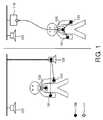
本発明の典型的な応用は、図1に記載されるものにおいて見つけられ、これは、ボディエリアネットワーク(BAN)を示す。体に取り付けられた、又は例えば接着剤で結合されたセンサ101、103は、ECG、SpO2飽和度及び血圧を測定し、患者情報センタ107に対する無線リンクを確立し、前記患者に関するデータを送信するのに使用される。 A typical application of the present invention is found in what is described in FIG. 1, which shows a body area network (BAN).
図1に示されるのは、ボディエリアネットワークの使用の典型である2つのシナリオである。ベッドに横たわる患者が、図1の左側に示され、起きて病院を歩き回る患者が、右側に示される。前記ベッドに横たわる患者の場合、送受信装置は、測定センサ及びIEEE規格802.15.4で動作する送受信器を取り付けられる。センサ101は、ベッドのそばに配置された患者モニタ105に直接的にリンクされる。患者モニタ105は、例えば医療スタッフに対するステーションとして機能する部屋に配置された患者情報センタ107に直接的にリンクされる。 Shown in FIG. 1 are two scenarios that are typical of the use of body area networks. A patient lying on the bed is shown on the left side of FIG. 1, and a patient who wakes up and walks around the hospital is shown on the right side. In the case of a patient lying on the bed, the transmitter / receiver is fitted with a measurement sensor and a transmitter / receiver operating according to IEEE standard 802.15.4. The
図1の右側において、前記センサからのデータを受信する収集センタとして及び例えばハブのようなプロトコルコンバータとして同時に機能する送受信装置103が、提供される。この実施例において、前記センサは、まず、短距離RFプロトコルを用いてプロトコルコンバータ103と通信し、プロトコルコンバータ103は、中距離RFプロトコルにおいて、例えばWLANを介して、アクセスポイント113に前記データを送信し、これは、患者情報センタ107に対する無線リンクを確立する。 On the right side of FIG. 1, a
測定値の無線取得は、前記患者が自由に動き回ることを可能にし、結果的に、前記通信がオンボディ指向又はオフボディ指向である通信として区別される要望が生じ、これにより適切な送信プロトコルが常に使用されることができる。 The wireless acquisition of measured values allows the patient to move around freely, resulting in the desire to distinguish the communication as on-body or off-body oriented communication, which ensures that the appropriate transmission protocol is Can always be used.
オンボディ通信に対する典型的なプロトコルは、規格IEEE 802.15.4の下の短距離RFプロトコルであり、この規格は、しばしば、誤ってZigBeeと称される。この規格は、低速度無線パーソナルエリアネットワークに対する物理層及びMAC層を規定する。この規格の下で、送受信装置は、ネットワークコーディネータの役割を引き受ける。この実施例において、前記ネットワーク上でオンにされる最初の装置が、前記ネットワークコーディネータである。前記ネットワークコーディネータは、前記ネットワークの個別のユーザ間のデータトラフィックを整理する責任がある。このタスクは、一方で、前記無線チャネルをタイムスロットに分割することを有し、前記タイムスロットは、送信側及び受信側においてデータが交換される短い時間間隔であり、この場合、前記チャネルに対するアクセスは、例えば保証される又は保証されないアクセス権を与える規則のような、以下の異なる規則により付与されることができる。前記ネットワークコーディネータは、この規格IEEE 802.15.4によってスーパーフレーム構造への前記無線チャネルの分割を規定する。これが意味するのは、前記ネットワークコーディネータが、同期信号としてビーコンペイロードを発し、このようにして好ましくは16のタイムスロットの時間ベース構造をプリセットすることである。データペイロードにより意味されるのは、輸送される場合にユニットとして扱われる複数のビットである。前記データペイロードは、好ましくは、持続時間がタイムスロットの持続時間と同じ長さを持つように設計される。前記ビーコンペイロードは、同時に、同期信号及び前記無線チャネルに対する設定情報のキャリアである。スーパーフレームは、好ましくは全て同じ長さを持ち、かつデータペイロードにより占有されることができる16の時間間隔を有する。前記データペイロードは、この場合、アクティブデータペイロードとして又は非アクティブ若しくはインアクティブデータペイロードとしてマークされることができる。アクティブデータペイロード又はアクティブ時間間隔により意味されるのは、前記データペイロード又は前記時間間隔が、前記ネットワーク上の全てのユーザがいつでも送信又は受信でき、前記ビーコンペイロードにおいて示されるコマンドにより指示される通りに送信又は受信に切り換えられることができる期間を構成することである。用語非アクティブデータペイロード又は非アクティブタイムスロットは、前記ネットワーク上の装置が、この時間中に前記エネルギ節約スリープモードに切り替えられ、前記送受信装置の送信器及び/又は受信器がオフに切り換えられることを意味する。 A typical protocol for on-body communication is the short-range RF protocol under the standard IEEE 802.15.4, which is often mistakenly referred to as ZigBee. This standard defines a physical layer and a MAC layer for low-speed wireless personal area networks. Under this standard, the transmitting / receiving device assumes the role of a network coordinator. In this embodiment, the first device turned on on the network is the network coordinator. The network coordinator is responsible for organizing data traffic between individual users of the network. This task, on the other hand, comprises dividing the radio channel into time slots, which are short time intervals in which data is exchanged on the transmitting side and the receiving side, in which case access to the channel Can be granted according to the following different rules, such as rules that grant guaranteed or unguaranteed access rights. The network coordinator defines the division of the radio channel into superframe structures according to this standard IEEE 802.15.4. This means that the network coordinator emits a beacon payload as a synchronization signal and thus presets a time base structure of preferably 16 time slots. By the data payload is meant a plurality of bits that are treated as a unit when transported. The data payload is preferably designed so that its duration has the same length as the duration of the time slot. The beacon payload is a carrier for setting information for the synchronization signal and the radio channel at the same time. The superframe preferably has the same length and has 16 time intervals that can be occupied by the data payload. The data payload can in this case be marked as an active data payload or as an inactive or inactive data payload. By active data payload or active time interval is meant that the data payload or time interval can be transmitted or received at any time by all users on the network and as indicated by the command indicated in the beacon payload. To configure a period of time that can be switched to transmission or reception. The term inactive data payload or inactive time slot means that a device on the network is switched to the energy saving sleep mode during this time and the transmitter and / or receiver of the transceiver device is switched off. means.
本発明による送受信装置の一実施例が、図2aに示される。前記装置は、オンボディ通信に対する第1のアンテナシステム201及びオフボディ通信に対する第2のアンテナシステム203がスイッチ213又は同様の適切な装置を用いて送受信器205に割り当てられることができる無線周波数(RF)送受信器205を有する。この実施例において、このプロセスは、前記送受信器により制御される。しかしながら、他の実施例において、前記割り当ては、例えばプロセッサ209のような他のユニットにより制御されてもよい。送受信装置219は、プロセッサ209、メモリ211及び測定値を取得するセンサ207をも有する。一実施例において、送受信器205、切り替え装置213、第1のアンテナシステム201及び第2のアンテナシステム203を有する送受信装置219は、患者モニタ105又はハブ103の形を取りうる。図2bに示される代替実施例において、送受信装置219は、ハブ又はプロトコルコンバータ103の形式の場合に、1以上の送受信器又は2より多いアンテナシステム201、203、221を有してもよい。基本的なアイデアは、オンボディ通信に対するアンテナシステム201とオフボディ通信に対するアンテナシステム203との間で切り換えることができ、したがって、多くの場合、最適化された受信又は送信極線図が送受信器205に対して利用可能であることを可能にすることである。 One embodiment of a transceiver device according to the present invention is shown in FIG. 2a. The apparatus includes a radio frequency (RF) at which a
図3は、オンボディ303及びオフボディ305通信を対象とした個別のタイムスロット309を持つスーパーフレーム311を示す。ビーコンペイロード301を用いて、前記コーディネータは、前記スーパーフレームの構造がどのように構成されるか、及びいずれのタイムスロットが、非アクティブ期間307又はオンボディ及びオフボディ通信に対する期間303、305であることを意図されるかをネットワークユーザに通知する。オンボディ通信303を対象とする時間中に、前記ネットワーク上の全ての送受信器205は、オンボディに構成され、所定の場合に対してこれがどちらのアンテナシステムであっても、オンボディ通信に対して第1のアンテナシステム201を使用し、これに対し、オフボディ通信を対象とする時間305中に、前記ネットワーク上の全ての送受信器205は、所定の場合にこれがいずれであっても、オフボディ通信に対する第2のアンテナシステム203に対するリソースを持つ。非アクティブ期間307としてマークされる時間中に、全ての装置は、スリープモードに入り、この場合、送受信器205は、例えば停止され、これは、送受信装置219の電流消費が非常に低いことを意味する。 FIG. 3 shows a
図4に示されるのは、本発明による新しいスーパーフレーム構造311である。この構造において、オンボディ通信及びオフボディ通信に対してそれぞれ設計されたコンテンションアクセス期間(CAP)401、403と称されるものが提供される。オンボディCAP401中に、オンボディに構成されたセンサのみが、競争又は競合において、前記チャネルを使用する権利を取得することを可能にされ、このようにして、互いと通信することを可能にされる。前記無線チャネル上の衝突を回避するために、ボディセンサは、送信前に、媒体、すなわち前記無線チャネルが、フリーであるかどうかを確認する(リッスンビフォアトーク、CSMA/CA)。同様のプロセスは、オフボディCAP403の場合に実行され、この場合に、オンボディで構成されたセンサがオフボディ装置と通信することを可能にし、逆にオフボディ装置がオンボディで構成されたセンサに対するリンクを確立することを可能にする。リッスンビフォアトーク原理は、後者の場合にも適用される。前記無線チャネルが、他の無線システムと共有され、全てのユーザが、互いと干渉することを回避するためにリッスンビフォアトーク原理で前記チャネルにアクセスするので、前記CAPは、好ましくは、不定期な、孤立した又は間欠的な通信に対して設計される。 Shown in FIG. 4 is a
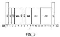
図5において、保証タイムスロット(GTS)501、502、503、504、505、506、507への前記スーパーフレームの時間による分割の一実施例が示される。これの有利な結果は、前記無線チャネルがアクセスされる場合に、ネットワークコーディネータの使用のため、衝突の可能性が低いことである。データのスループットも、これにより増大され、これは、エネルギ消費の減少が関与する限り既知の効果を持つ。例えば、オンボディ通信に対する保証タイムスロットGTS501中に、ボディセンサAは、ボディセンサBと連絡しており、この場合、装置Aは、リッスンビフォアトーク規則を見ることなしに装置Bを目標とするパケットの発信に対してタイムスロットGTS501全体を使用する。オフボディ装置が保証タイムスロット(GTS)505、506、507を用いて他のオフボディ装置と通信することを意図する同様の成り行きに対する実施例が提供される。前記GTSは、データの定期的な交換を行うユーザ間の通信を対象とする。GTSの割り当ては、データトラフィックの公安が不定期であるが、同じ周波数チャネル上で動作する他のユーザとの衝突を回避することを意図される。 In FIG. 5, one embodiment of the time-based division of the superframe into guaranteed time slots (GTS) 501, 502, 503, 504, 505, 506, 507 is shown. The advantageous result of this is that when the radio channel is accessed, the possibility of collision is low due to the use of a network coordinator. Data throughput is also increased thereby, which has a known effect as long as a reduction in energy consumption is involved. For example, during a guaranteed time slot GTS501 for on-body communication, body sensor A communicates with body sensor B, in which case device A targets device B without looking at the listen-before-talk rule. The entire
図6は、スーパーフレーム構造311の実施例を示す。前記スーパーフレーム構造は、前記ネットワークコーディネータのビーコンペイロード301で始まる。前記ビーコンペイロードは、スーパーフレーム構造311が分割される様式に関するコマンドを含む。スーパーフレーム構造311のアクティブ期間は、オンボディ通信に対するCAP(コンテンションアクセス期間)タイムスロット601及びオフボディ通信に対するCAPタイムスロット604、並びにオンボディ通信に対するGTS(保証タイムスロット)タイムスロット602、603及びオフボディ通信に対するGTSタイムスロット605、606、607を有する。 FIG. 6 shows an example of a
タイムスロットを予約する方法が、図7に示される。CAP及びGTSを用いるオフボディ通信及びオンボディ通信に対するタイムスロットが割り当てられることを可能にするために、タイムスロットは、前記ネットワークコーディネータにおいて予約されることができる。この目的で、装置は、保証タイムスロット仕様(GTSスペック)703を用いて通信要件を指定するパラメータ、例えば要求されるタイムスロットの数、送信アドレス及び受信アドレス705を、タイムスロット要求(TS要求)701の形式で前記ネットワークコーディネータに送信する。 A method for reserving a time slot is shown in FIG. To allow time slots for off-body and on-body communications using CAP and GTS to be assigned, time slots can be reserved at the network coordinator. For this purpose, the device specifies parameters that specify communication requirements using a guaranteed time slot specification (GTS specification) 703, such as the number of required time slots, a transmission address and a
図8は、保証タイムスロット要求(GTS要求)803に基づいて、CAP及びGTSを用いてオフボディ及びオンボディ通信に対して前記ネットワークコーディネータに送信されるビーコンペイロード送信のコンテンツ(スーパーフレームスペック)801を示す。前記ネットワークコーディネータは、その時点で適用するスーパーフレーム構造を前記ネットワークユーザに通知する。一実施例は、リスト807が記憶されたビーコンペイロードの送信を有し、リスト807は、前記タイムスロットが発生するシーケンス、データペイロードの受信者及び受け手の詳細、オンボディ又はオフボディ配向の形式の配向、送信権がCAPにより与えられるのか又はGTSにより与えられるのか、期間がアクティブであるのか又は非アクティブであるのか及び持続時間を有する。 FIG. 8 shows beacon payload transmission content (superframe specification) 801 transmitted to the network coordinator for off-body and on-body communication using CAP and GTS based on a guaranteed time slot request (GTS request) 803. Indicates. The network coordinator notifies the network user of the superframe structure to be applied at that time. One embodiment comprises the transmission of a beacon payload with a
図9は、タイムスロットへの分割の詳細な結合した例を示す。スーパーフレーム仕様(スーパーフレームスペック)を与えるビーコンペイロード801は、データアイテム807、すなわち、タイムスロット持続時間(マイクロ秒)、オンボディCAPタイムスロットの数、オンボディGTSタイムスロットの数、個別のGTSタイムスロットの仕様、オフボディCAPタイムスロットの数、オフボディGTSタイムスロットの数、個別のオフボディGTSタイムスロットの仕様及び非アクティブタイムスロットの数を有する。一般にビーコンペイロード801において既知にされるように前記ネットワークコーディネータに送信される保証タイムスロット(GTSスペック)に対する要求803は、タイムスロットの数、送信器アドレス及び受信器アドレスに関するデータ805を含み、送信の場合に、ビーコンペイロード901は、例えば前記パラメータを与えるデータ及び数字903の列の形式の前記スーパーフレームの使用を含む。前記ビーコンペイロードによりプリセットされたものに従って、前記スーパーフレームは、この場合、図9の下の部分に示される形式でまとめられる。 FIG. 9 shows a detailed combined example of the division into time slots. The
前記ネットワークコーディネータにより発信されたスーパーフレームを用いて、前記ビーコンペイロードのコンテンツは、前記ビーコンペイロード内で与えられた情報を参照することにより、いつオンボディ及びオフボディ通信が行われるかを全ての装置に通知する。これに基づき、前記送受信装置は、特に人体の長手方向に向けられた全方向極線図を持つことを特徴とするオンボディ通信に対するアンテナシステム、又は人体から離れる方に向けられた極線図を持つことを特徴とするオフボディ通信に対するアンテナシステムを前記送受信器に割り当てる。 By using the superframe transmitted by the network coordinator, the content of the beacon payload refers to the information given in the beacon payload, so that when all on-body and off-body communications are performed Notify Based on this, the transmitting / receiving device has an antenna system for on-body communication characterized in that it has an omnidirectional polar diagram particularly directed in the longitudinal direction of the human body, or a polar diagram directed to the direction away from the human body. An antenna system for off-body communication characterized by having is assigned to the transceiver.
前記ネットワークコーディネータの機能がオンボディ装置により実行される好適な実施例において、前記ビーコンペイロードは、オンボディ通信に対する第1のアンテナシステム及びオフボディ通信に対する第2のアンテナシステムをも用いて並列に送信される。 In a preferred embodiment where the function of the network coordinator is performed by an on-body device, the beacon payload is transmitted in parallel also using a first antenna system for on-body communication and a second antenna system for off-body communication. Is done.
図10は、オンボディ通信に対するアンテナシステムに対する好適な極線図を描く。この種のアンテナシステムは、好ましくは、全方向極線図1001を持つ。一実施例において、前記極線図は、特に人体の長手方向に向けられることを意図される。この種の全方向極線図は、例えば、人体の表面に垂直に配置された点において最大範囲を持つ方向に向けられるように配置される場合に、単一のダイポールアンテナ又は単一のモノポールアンテナにより生成される。しかしながら、適切な極線図を持つアンテナ方向又はアンテナ装置が、例えばスロット化アンテナ又はプリント回路基板アンテナのような、アンテナ又はストリップアンテナとして使用されることも可能である。基本的に、意図は、前記アンテナが、前記送受信器と一緒に又は別々に、図10に示される極線図1001に近い極線図を持つように構成されることである。 FIG. 10 depicts a preferred polar diagram for an antenna system for on-body communication. This type of antenna system preferably has an omnipolar diagram 1001. In one embodiment, the polar diagram is specifically intended to be oriented in the longitudinal direction of the human body. An omnidirectional polar diagram of this kind is a single dipole antenna or a single monopole, for example when it is arranged to be oriented in a direction that has a maximum extent at a point arranged perpendicular to the surface of the human body. Generated by the antenna. However, an antenna orientation or antenna device with a suitable polar diagram can also be used as an antenna or strip antenna, for example a slotted antenna or a printed circuit board antenna. Basically, the intent is that the antenna be configured to have a polar diagram similar to the polar diagram 1001 shown in FIG. 10, with or separately from the transceiver.
最適化された極線図が存在する場合に、かつ送信器と受信器との間の距離が一般に小さいという仮定の下で、放射されるパワーは、非常に低いレベルの送信パワーに減少されることができる。また、オンボディ通信に対する送信パワーは、オフボディ通信に対する送信パワーより低いことができ、これにより特に人体に対する悪影響の減少が最適化される。 In the presence of an optimized polar diagram and under the assumption that the distance between the transmitter and receiver is generally small, the emitted power is reduced to a very low level of transmit power be able to. Also, the transmission power for on-body communication can be lower than the transmission power for off-body communication, thereby optimizing the reduction of adverse effects, particularly on the human body.
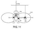
図11は、オフボディ通信に対するアンテナ図1101の一実施例を示す。オフボディ通信に対するアンテナシステム及び送受信器の実施例に適切なのは、人体に対する低い浸透深さを持つ高い動作周波数である。人体への比較的高い浸透深さ、及びこれに関連して強力な容量結合を持つ低い周波数は、中距離又は長距離通信リンクに対して適切ではない。前記送受信器又は前記送受信装置101、ハブ103又はプロトコルコンバータ103等のいずれかにおける適切に決定された位置における前記アンテナの配置により、極線図1101が、例えば患者モニタ105のような患者からオフボディで構成された送受信器が、配向された極線図により到達されることができるように配向されることが意図される。パッチアンテナは、フットプリントに対する前記アンテナの長手範囲が人体の表面に平行に構成される場合に、オフボディに向けられた配向された極線図を発することができる。オンボディ通信と比較して、より高い送信パワーがオフボディ通信に対して使用されるので、ストリップアンテナ構成又はパッチアンテナが、好ましくは、使用される。これは、ストリップアンテナ構成が配向された極線図を持つので、人体が高レベルの送信パワーに対して遮蔽されることを可能にする。 FIG. 11 shows an example of an antenna diagram 1101 for off-body communication. Suitable for antenna system and transceiver embodiments for off-body communication are high operating frequencies with low penetration depth for the human body. The relatively high penetration depth into the human body and the associated low frequency with strong capacitive coupling is not appropriate for medium or long range communication links. Due to the placement of the antenna at a suitably determined location in either the transceiver or the
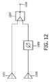
図12は、例として、少なくとも2つのアンテナ1201、1203を持つアンテナアレイを示す概略図である。しかしながら、より多数のアンテナが使用されることも可能である。放射される無線周波数パワーは、少なくとも2つの同相のアンテナ信号に分離される。前記2つのアンテナ信号の発信パラメータは、この場合に異なって重みづけされることができる。一実施例において、1つのアンテナ信号は、位相シフタ1205を用いて他方に対して遅延されることができる。位相シフタ1205自体は、マイクロプロセッサを用いて無線周波数システムを制御するシステムにより又はプロセッサにより制御される。前記位相シフタを用いて、位相シフタ1205は、例えばオンボディ又はオフボディ通信のような存在する実際の要件に対して前記アンテナの極線図の向きをマッチさせる。 FIG. 12 is a schematic diagram showing an antenna array having at least two
好適な実施例において、異なって偏波されたアンテナ構成が、第1のアンテナシステム1201及び第2のアンテナシステム1203に対して使用される。このようにして、オンボディ通信に対するリンクは、例えば、水平に偏波されたアンテナを用いて作成されることができるのに対し、オフボディ通信に対するリンクは、垂直に偏波されたアンテナにより作成されることができる。他の実施例において、垂直及び水平に向けられたアンテナは、右旋性又は左旋性円偏波を与えるアンテナにより置き換えられることもできる。 In the preferred embodiment, differently polarized antenna configurations are used for the
好適な実施例において、単一のアンテナアレイも、前記第1の及び第2のアンテナシステムとして使用されることができ、前記アンテナの第1のグループに対する送信信号のフィードは、直接的に行われ、前記アンテナアレイのアンテナの第2のグループに対する送信信号のフィードは、位相シフトとともに行われる。このようにして、オンボディ及びオフボディ通信に対する異なる極線図が、単一のアンテナアレイを用いて生成されることができる。前記送受信器は、この目的で位相シフタ1205を持つ。この種の実施例は、前記極線図が好適な方向に操作されることを可能にする。これは、患者が病院を歩き回り、前記患者が身に付けたセンサが周囲とデータを交換している場合に好適である実施例である。 In a preferred embodiment, a single antenna array can also be used as the first and second antenna systems, and the transmission of the transmitted signal to the first group of antennas is done directly. The transmission of the transmission signal to the second group of antennas of the antenna array is performed with a phase shift. In this way, different polar diagrams for on-body and off-body communication can be generated using a single antenna array. The transceiver has a
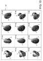
図13は、異なる位相シフトに対する異なる極線図1301を示す。代替的に、例えばオンボディリンクに対して使用される容量性RFアンテナシステムのような低周波アンテナシステムを使用することも可能である。この種の構成は、容量性電気導体として人体を使用する。 FIG. 13 shows different polar diagrams 1301 for different phase shifts. Alternatively, it is also possible to use a low frequency antenna system, such as a capacitive RF antenna system used for on-body links. This type of configuration uses the human body as a capacitive electrical conductor.
本発明は、記述及び図面を用いて詳細に記載及び描写されているが、前記記述及び図面は、単に説明的であり、限定的ではないと見なされるべきである。本発明は、開示されている実施例に限定されない。 While the invention has been described and illustrated in detail using the description and drawings, the description and drawings are to be regarded merely as illustrative and not restrictive. The invention is not limited to the disclosed embodiments.
開示された実施例に対する他の変形例は、実際に実施する又は前記記述又は図面又は添付の請求項を検討する場合に当業者が思い付きうる。請求項に関して、単語"有する"は、他のより幅広い要素又はステップを除外しない。また、不定冠詞"1つの"は、複数を除外しない。単一のプロセッサ又は1つのユニットは、請求項で述べられた単一の又は複数の機能を実行することができる。フィーチャが個別の請求項、又は互いに独立に与えられた請求項に現れるという単なる事実は、このようなフィーチャの組み合わせも有利に使用されることができる可能性を除外しない。コンピュータプログラムは、別個のコンポーネントとして又はハードウェアに対するアクセサリとして供給される、例えば光記憶媒体又は半導体記憶媒体のようなデータ運搬媒体において記憶又は販売されることができる。コンピュータプログラムは、例えばインターネット上で又は有線若しくは無線電気通信システムを介してのような異なる形で配信されることもできる。請求項内の参照番号は、本発明を限定すると解釈されるべきでない。 Other variations to the disclosed embodiments may occur to those skilled in the art in actual practice or upon review of the above description or drawings or appended claims. With respect to the claims, the word “comprising” does not exclude other broader elements or steps. Further, the indefinite article “one” does not exclude a plurality. A single processor or unit may perform the single or multiple functions recited in the claims. The mere fact that features appear in individual claims or in claims given independently of each other does not exclude the possibility that combinations of such features can also be used to advantage. The computer program can be stored or sold on a data carrier medium, such as an optical storage medium or a semiconductor storage medium, supplied as a separate component or as an accessory to the hardware. The computer program can also be distributed in different ways, for example over the Internet or via a wired or wireless telecommunication system. Any reference signs in the claims should not be construed as limiting the invention.
101:センサ
103:ハブ
105:患者モニタ
107:患者情報センタ
109:IEEE 802.15.4短距離無線
111:IEEE 802.11中距離無線
201:オンボディ通信に対するアンテナシステム
203:オフボディ通信に対するアンテナシステム
205:送受信器
207:センサ
209:プロセッサ
211:メモリ
213:スイッチ
215:オンボディ通信に対するアンテナ1
217:オフボディ通信に対するアンテナ2
219:送受信装置
301:ビーコンペイロード又はビーコン
303:オンボディ通信
305:オフボディ通信
307:非アクティブ期間
309:タイムスロット
311:スーパーフレーム
313:時間
401:オンボディコンテンションアクセス期間(CAP)
403:オフボディコンテンションアクセス期間(CAP)
501:オンボディGTS1
502:オンボディGTS2
503:オンボディGTS3
504:オンボディGTS4
505:オフボディGTS1
506:オフボディGTS2
507:オフボディGTS3
601:オンボディCAP
602:オンボディGTS1
603:オンボディGTS2
604:オフボディCAP
605:オフボディGTS1
606:オフボディGTS2
607:オフボディGTS3
701:タイムスロット要求
703:GTS仕様
705:GTS仕様のコンテンツ
707:タイムスロット要求のコンテンツ
801:スーパーフレーム要求
803:GTS仕様
805:GTS仕様のコンテンツ
807:スーパーフレーム要求のコンテンツ
901:ビーコンペイロード
903:ビーコンペイロードのコンテンツ
905:ユーザ2からユーザ3へのオンボディ無線トラフィック
907:ユーザ4からユーザ5へのオンボディ無線トラフィック
911:ユーザ2からユーザ1へのオフボディ無線トラフィック
913:ユーザ3からユーザ1へのオフボディ無線トラフィック
915:ユーザ5からユーザ1へのオフボディ無線トラフィック
1001:極線図
1101:極線図
1201:アンテナシステム1
1203:アンテナシステム2
1205:位相シフタ(0ないし360°)
1207:信号スプリッタ
1209:無線周波数入力
1301:極線図101: Sensor 103: Hub 105: Patient monitor 107: Patient information center 109: IEEE 802.15.4 short-range radio 111: IEEE 802.11 medium-range radio 201: Antenna system for on-body communication 203: Antenna system for off-body communication 205: Transmission / reception 207: Sensor 209: Processor 211: Memory 213: Switch 215:
217:
219: Transmission / reception device 301: Beacon payload or beacon 303: On-body communication 305: Off-body communication 307: Inactive period 309: Time slot 311: Super frame 313: Time 401: On-body contention access period (CAP)
403: Off-body contention access period (CAP)
501: On-body GTS1
502: On-body GTS2
503: On-body GTS3
504: On-body GTS4
505: Off-body GTS1
506: Off-body GTS2
507: Off-body GTS3
601: On-body CAP
602: On-body GTS1
603: On-body GTS2
604: Off-body CAP
605: Off-body GTS1
606: Off-body GTS2
607: Off-body GTS3
701: Time slot request 703: GTS specification 705: GTS specification content 707: Time slot request content 801: Super frame request 803: GTS specification 805: GTS specification content 807: Super frame request content 901: Beacon payload 903: Beacon payload content 905: On-body wireless traffic from
1203:
1205: Phase shifter (0 to 360 °)
1207: Signal splitter 1209: Radio frequency input 1301: Polar diagram
Claims (15)
Translated fromJapaneseオンボディ通信に対して1以上のデータペイロードを予約し、当該データペイロードにより占有される時間間隔に対して前記第1のアンテナシステムを前記送受信器に割り当て、
オフボディ通信に対して1以上のデータペイロードを予約し、当該データペイロードにより占有される時間間隔に対して前記第2のアンテナシステムを前記送受信器に割り当てる、
ように設計され、
前記オンボディ通信に対する第1のアンテナシステムが、人体の長手方向に向けられた全方向極線図を持ち、
前記オフボディ通信に対する第2のアンテナシステムが、人体から離れる方に向けられた極線図を持つ、
送受信装置。In a transmission / reception apparatus that processes a medium access control protocol or abbreviated MAC protocol, used by a transceiver having a first antenna system for on-body communication and a second antenna system for off-body communication, the transmission / reception apparatus comprises:
Reserve one or more data payloads for on-body communication and assign the first antenna system to the transceiver for the time interval occupied by the data payloads;
Reserving one or more data payloads for off-body communication and assigning the second antenna system to the transceiver for a time interval occupied by the data payloads;
Designed and
The first antenna system for on-body communication has an omnidirectional polar diagram oriented in the longitudinal direction of the human body;
The second antenna system for off-body communication has a polar diagram directed away from the human body;
Transmitter / receiver.
患者の体の上に配置された送受信装置と、
オフボディで配置された患者モニタと、
を有するシステム。The system for wireless communication between at least one transceiver device according to claim 1,
A transceiver device disposed on the patient's body;
A patient monitor placed off-body,
Having a system.
前記患者モニタを介するオフボディ通信リンク、又は
前記送受信装置に対するオンボディ通信リンクであって、中距離RFリンクを介する前記送受信装置を用いるデータの交換が第3のアンテナシステムを介して行われる、当該オンボディ通信リンク、
を有する、請求項9に記載のシステム。Said systemto exchange data with the arranged sensors and patient information center on the patient,the system comprising:
The off-body communication link via the patient monitor, or be on the body communications link to saidtransmitting and receiving apparatus, exchange of data using thetransceiver via a medium range RF link is performed through the third antenna system, the On-body communication link,
10. The system ofclaim 9, comprising:
少なくとも1つのビーコンペイロードと、
20mまで、好ましくは2mまでの距離にわたるオンボディ通信に対する少なくとも1つのデータペイロードであって、オンボディ通信に対する第1のアンテナシステムが、オンボディ通信に対するデータペイロードにより占有される時間間隔中に使用され、前記オンボディ通信に対する第1のアンテナシステムが、人体の長手方向に向けられた全方向極線図を持つ、当該オンボディ通信に対する少なくとも1つのデータペイロードと、
100mまで、好ましくは4mまでの距離にわたるオフボディ通信に対する少なくとも1つのデータペイロードであって、オフボディ通信に対する第2のアンテナシステムが、オフボディ通信に対するデータペイロードにより占有される時間間隔中に使用され、前記オフボディ通信に対する第2のアンテナシステムが、人体から離れる方に向けられた極線図を持つ、当該オフボディ通信に対する少なくとも1つのデータペイロードと、
を有する、MACプロトコル方法。In a MAC protocol method in which a transmitting / receiving device divides a transmission channel into superframes, the superframes follow each other in time, and the superframes are:
At least one beacon payload;
At least one data payload for on-body communication over a distance of up to 20 m, preferably up to 2 m, wherein the first antenna system for on-body communication is used during the time interval occupied by the data payload for on-body communication At least one data payload for the on-body communication, wherein the first antenna system for the on-body communication has an omnidirectional polar diagram oriented in the longitudinal direction of the human body;
At least one data payload for off-body communication over a distance of up to 100 m, preferably up to 4 m, wherein a second antenna system for off-body communication is used during the time interval occupied by the data payload for off-body communication At least one data payload for the off-body communication, wherein the second antenna system for the off-body communication has a polar diagram directed away from the human body;
A MAC protocol method comprising:
オンボディ通信に対して1以上のデータペイロードを予約し、これらのデータペイロードにより占有される時間間隔に対して、前記送受信器に割り当てられたアンテナシステムが、前記第1のアンテナシステムである、及び/又は
オフボディ通信に対して1以上のデータペイロードを予約し、これらのデータペイロードにより占有される時間間隔に対して、前記送受信器に割り当てられたアンテナシステムが、前記第2のアンテナシステムである、
ようにデータペイロードに対する時間間隔に前記スーパーフレームを分割する、請求項12に記載のMACプロトコル方法。Each transceiver device
One or more data payloads reserved for on the body communications, with respect to the time interval occupied by these data payload antenna system assigned to said transceiveris apre Symbol first antenna system, and / or one or more data payloads to reserved for off body communications, with respect to the time interval occupied by these data payload antenna system assigned to said transceiveris pre-Symbol second antenna system Is,
The MAC protocol method according to claim 12, wherein the superframe is divided into time intervals for the data payload as follows.
Applications Claiming Priority (3)
| Application Number | Priority Date | Filing Date | Title |
|---|---|---|---|
| EP09151872 | 2009-02-02 | ||
| EP09151872.0 | 2009-02-02 | ||
| PCT/IB2010/050382WO2010086813A1 (en) | 2009-02-02 | 2010-01-28 | Transceiver device for on-body and off-body communications |
Publications (3)
| Publication Number | Publication Date |
|---|---|
| JP2012517135A JP2012517135A (en) | 2012-07-26 |
| JP2012517135A5 JP2012517135A5 (en) | 2013-03-14 |
| JP5647151B2true JP5647151B2 (en) | 2014-12-24 |
Family
ID=42109879
Family Applications (1)
| Application Number | Title | Priority Date | Filing Date |
|---|---|---|---|
| JP2011547042AActiveJP5647151B2 (en) | 2009-02-02 | 2010-01-28 | Transmitter / receiver for on-body and off-body communication |
Country Status (7)
| Country | Link |
|---|---|
| US (1) | US8750222B2 (en) |
| EP (1) | EP2392185B1 (en) |
| JP (1) | JP5647151B2 (en) |
| CN (1) | CN102301814B (en) |
| BR (1) | BRPI1005356A2 (en) |
| RU (1) | RU2554559C2 (en) |
| WO (1) | WO2010086813A1 (en) |
Families Citing this family (23)
| Publication number | Priority date | Publication date | Assignee | Title |
|---|---|---|---|---|
| US9596989B2 (en) | 2009-03-12 | 2017-03-21 | Raytheon Company | Networked symbiotic edge user infrastructure |
| US8897198B2 (en) | 2011-01-14 | 2014-11-25 | Covidien Lp | Medical device wireless network architectures |
| US8798527B2 (en) | 2011-01-14 | 2014-08-05 | Covidien Lp | Wireless relay module for remote monitoring systems |
| US9495511B2 (en) | 2011-03-01 | 2016-11-15 | Covidien Lp | Remote monitoring systems and methods for medical devices |
| US8855550B2 (en) | 2011-01-14 | 2014-10-07 | Covidien Lp | Wireless relay module having emergency call functionality |
| US8903308B2 (en) | 2011-01-14 | 2014-12-02 | Covidien Lp | System and method for patient identification in a remote monitoring system |
| US8811888B2 (en) | 2011-01-14 | 2014-08-19 | Covidien Lp | Wireless relay module for monitoring network status |
| US9020419B2 (en) | 2011-01-14 | 2015-04-28 | Covidien, LP | Wireless relay module for remote monitoring systems having power and medical device proximity monitoring functionality |
| US8818260B2 (en) | 2011-01-14 | 2014-08-26 | Covidien, LP | Wireless relay module for remote monitoring systems |
| US8694600B2 (en) | 2011-03-01 | 2014-04-08 | Covidien Lp | Remote monitoring systems for monitoring medical devices via wireless communication networks |
| US8878735B2 (en)* | 2012-06-25 | 2014-11-04 | Gn Resound A/S | Antenna system for a wearable computing device |
| CN104620245A (en) | 2012-09-13 | 2015-05-13 | 柯惠有限合伙公司 | Docking station for enteral feeding pump |
| US9031020B2 (en)* | 2012-09-26 | 2015-05-12 | Cisco Technology, Inc. | Using multiple radios to provide service on the same channel to support a new standard while maintaining compatibility with legacy devices |
| EP2949054B1 (en) | 2013-01-25 | 2016-06-29 | ABB Research Ltd. | A method for providing reliable wireless communication in a wireless sensor network |
| JP6115629B2 (en)* | 2013-03-12 | 2017-04-19 | 富士通株式会社 | Wireless communication system, wireless communication method, transmission apparatus, control method, and control program |
| US8953547B2 (en)* | 2013-03-29 | 2015-02-10 | Olympus Corporation | Power-saving TDMA MAC for wireless body area networks |
| USD746441S1 (en) | 2013-09-13 | 2015-12-29 | Covidien Lp | Pump |
| WO2016012738A1 (en)* | 2014-07-22 | 2016-01-28 | Kabushiki Kaisha Toshiba | Antenna and method of manufacturing an antenna |
| US20160321846A1 (en)* | 2015-05-01 | 2016-11-03 | Honeywell International Inc. | Security access system using a body area network |
| US9943229B1 (en)* | 2016-12-08 | 2018-04-17 | General Electric Copany | Systems and methods for monitoring patient health |
| US10405374B2 (en)* | 2017-03-17 | 2019-09-03 | Google Llc | Antenna system for head mounted display device |
| JP2019022117A (en)* | 2017-07-19 | 2019-02-07 | ソニーセミコンダクタソリューションズ株式会社 | Communication device and communication system |
| CN111601387B (en)* | 2020-05-22 | 2022-07-12 | 电子科技大学 | Medium access control mechanism for digital energy integrated wireless sensor network |
Family Cites Families (19)
| Publication number | Priority date | Publication date | Assignee | Title |
|---|---|---|---|---|
| US6424820B1 (en)* | 1999-04-02 | 2002-07-23 | Interval Research Corporation | Inductively coupled wireless system and method |
| RU2199943C2 (en)* | 2001-02-16 | 2003-03-10 | Многопрофильное предприятие ООО "Элсис" | Method and device for recording pulse wave and biometric system |
| US7321580B1 (en) | 2002-10-18 | 2008-01-22 | Bbn Technologies Corp. | Directional carrier sense medium access for wireless nodes |
| US7149581B2 (en) | 2003-01-31 | 2006-12-12 | Medtronic, Inc. | Patient monitoring device with multi-antenna receiver |
| KR100552484B1 (en) | 2004-02-13 | 2006-02-15 | 삼성전자주식회사 | Wireless Media Approach |
| DE102004036878B4 (en) | 2004-07-29 | 2008-04-10 | Dräger Safety AG & Co. KGaA | Method and device for radio transmission of signals generated close to the body |
| RU43749U1 (en)* | 2004-09-28 | 2005-02-10 | Демин Александр Сергеевич | PHYSIOCONTROL DEVICE |
| US7978063B2 (en)* | 2004-12-13 | 2011-07-12 | Koninklijke Philips Electronics N.V. | Wireless network having body coupled communication for mobile patient monitoring |
| CN101170943A (en)* | 2005-05-06 | 2008-04-30 | 皇家飞利浦电子股份有限公司 | Wireless Medical Monitoring Equipment |
| US9059782B2 (en)* | 2005-06-01 | 2015-06-16 | Broadcom Corporation | Method and system for antenna and radio front-end topologies for a system-on-a-chip (SOC) device that combines bluetooth and IEEE 802.11 b/g WLAN technologies |
| US7778219B2 (en)* | 2005-11-17 | 2010-08-17 | San Diego Research Center, Inc. | Directional transmission and reception in a mobile wireless ad hoc network |
| JP4163717B2 (en)* | 2006-01-24 | 2008-10-08 | 日本電信電話株式会社 | Paging response system, paging device and response device |
| US7742816B2 (en)* | 2006-03-31 | 2010-06-22 | Medtronic, Inc. | Multichannel communication for implantable medical device applications |
| DE102007003634B3 (en) | 2006-09-14 | 2008-04-24 | IHP GmbH - Innovations for High Performance Microelectronics/Institut für innovative Mikroelektronik | Hardware-protocol accelerator module for connection safety-protocol level i.e. data link layer, of transceiver, is configured to search data blocks from space to transfer data blocks to bit transmission-protocol level of transmitting unit |
| JP4840043B2 (en)* | 2006-09-21 | 2011-12-21 | ソニー株式会社 | Wireless communication system and wireless communication apparatus |
| WO2008058219A2 (en) | 2006-11-07 | 2008-05-15 | Nonin Medical, Inc. | Wireless medical device communication system |
| US20080294020A1 (en)* | 2007-01-25 | 2008-11-27 | Demetrios Sapounas | System and method for physlological data readings,transmission and presentation |
| US20080287748A1 (en) | 2007-02-05 | 2008-11-20 | Demetrios Sapounas | System and method for physiological data readings, transmission and presentation |
| EP2214447B1 (en)* | 2009-01-29 | 2016-03-30 | Stichting IMEC Nederland | Access method and data frame structure for use in body area networks |
- 2010
- 2010-01-28RURU2011136480/08Apatent/RU2554559C2/ennot_activeIP Right Cessation
- 2010-01-28BRBRPI1005356Apatent/BRPI1005356A2/ennot_activeApplication Discontinuation
- 2010-01-28JPJP2011547042Apatent/JP5647151B2/enactiveActive
- 2010-01-28CNCN201080006352.8Apatent/CN102301814B/enactiveActive
- 2010-01-28WOPCT/IB2010/050382patent/WO2010086813A1/enactiveApplication Filing
- 2010-01-28USUS13/146,019patent/US8750222B2/enactiveActive
- 2010-01-28EPEP10703516.4Apatent/EP2392185B1/enactiveActive
Also Published As
| Publication number | Publication date |
|---|---|
| CN102301814B (en) | 2016-05-11 |
| CN102301814A (en) | 2011-12-28 |
| RU2011136480A (en) | 2013-03-10 |
| EP2392185A1 (en) | 2011-12-07 |
| US20110280224A1 (en) | 2011-11-17 |
| EP2392185B1 (en) | 2018-03-14 |
| WO2010086813A1 (en) | 2010-08-05 |
| JP2012517135A (en) | 2012-07-26 |
| US8750222B2 (en) | 2014-06-10 |
| RU2554559C2 (en) | 2015-06-27 |
| BRPI1005356A2 (en) | 2017-12-12 |
Similar Documents
| Publication | Publication Date | Title |
|---|---|---|
| JP5647151B2 (en) | Transmitter / receiver for on-body and off-body communication | |
| JP6775668B2 (en) | Systems and methods for waking up the device's wireless communication module | |
| Khan et al. | Wireless body area network (WBAN) for medical applications | |
| Rahim et al. | A comprehensive survey of MAC protocols for wireless body area networks | |
| US9402269B2 (en) | Simplified beaconing and channel reservation techniques for short range wireless networks | |
| EP2356733B1 (en) | Method and system of radio frequency (rf) power transmission in a wireless network | |
| KR101602968B1 (en) | Apparatus and method for operating piconets in body area networks | |
| US9468003B2 (en) | Medium access control (MAC) protocol for body area networks | |
| JP2012517135A5 (en) | ||
| Rathee et al. | Recent trends in Wireless Body Area Network (WBAN) research and cognition based adaptive WBAN architecture for healthcare | |
| Sruthi | Medium access control protocols for wireless body area networks: A survey | |
| EP2717647B1 (en) | Mac protocol in wireless body area network capable of processing emergency data and wireless network communication method using same | |
| Javaid et al. | Energy efficient mac protocols in wireless body area sensor networks-a survey | |
| Misra et al. | Random room mobility model and extra‐wireless body area network communication in hospital buildings | |
| KR20140017579A (en) | Method and device for selecting a channel according to a device's mobility | |
| US10708110B2 (en) | Super-frame realignment mechanism to enable inter-wireless sensor network communications | |
| KR101582690B1 (en) | How to set period in BAN | |
| EP2424304A1 (en) | Method and network manager device for scheduling a transmission of messages within a wireless network | |
| Dargie | A medium access control protocol that supports a seamless handover in wireless sensor networks | |
| Toumanari et al. | Performance analysis of IEEE 802.15. 6 and IEEE 802.15. 4 for wireless body sensor networks | |
| Wang et al. | IEEE 802.15. 4J: extend IEEE 802.15. 4 radio into the MBAN spectrum [Industry Perspectives] | |
| Kwak et al. | Power efficient wakeup mechanisms for wireless body area networks | |
| Uno et al. | A proposal of QoE based self-organized wireless system considering the measurement results in a major hospital | |
| Pandey et al. | MAC Protocols of Wireless Body Area Network: A Survey | |
| Xia et al. | MAC protocols |
Legal Events
| Date | Code | Title | Description |
|---|---|---|---|
| A521 | Request for written amendment filed | Free format text:JAPANESE INTERMEDIATE CODE: A523 Effective date:20130118 | |
| A621 | Written request for application examination | Free format text:JAPANESE INTERMEDIATE CODE: A621 Effective date:20130118 | |
| A977 | Report on retrieval | Free format text:JAPANESE INTERMEDIATE CODE: A971007 Effective date:20131121 | |
| A131 | Notification of reasons for refusal | Free format text:JAPANESE INTERMEDIATE CODE: A131 Effective date:20131203 | |
| A601 | Written request for extension of time | Free format text:JAPANESE INTERMEDIATE CODE: A601 Effective date:20140228 | |
| A602 | Written permission of extension of time | Free format text:JAPANESE INTERMEDIATE CODE: A602 Effective date:20140307 | |
| A521 | Request for written amendment filed | Free format text:JAPANESE INTERMEDIATE CODE: A523 Effective date:20140528 | |
| A131 | Notification of reasons for refusal | Free format text:JAPANESE INTERMEDIATE CODE: A131 Effective date:20140617 | |
| A521 | Request for written amendment filed | Free format text:JAPANESE INTERMEDIATE CODE: A523 Effective date:20140916 | |
| TRDD | Decision of grant or rejection written | ||
| A01 | Written decision to grant a patent or to grant a registration (utility model) | Free format text:JAPANESE INTERMEDIATE CODE: A01 Effective date:20141010 | |
| A61 | First payment of annual fees (during grant procedure) | Free format text:JAPANESE INTERMEDIATE CODE: A61 Effective date:20141106 | |
| R150 | Certificate of patent or registration of utility model | Ref document number:5647151 Country of ref document:JP Free format text:JAPANESE INTERMEDIATE CODE: R150 | |
| R250 | Receipt of annual fees | Free format text:JAPANESE INTERMEDIATE CODE: R250 | |
| R250 | Receipt of annual fees | Free format text:JAPANESE INTERMEDIATE CODE: R250 | |
| R250 | Receipt of annual fees | Free format text:JAPANESE INTERMEDIATE CODE: R250 | |
| R250 | Receipt of annual fees | Free format text:JAPANESE INTERMEDIATE CODE: R250 | |
| R250 | Receipt of annual fees | Free format text:JAPANESE INTERMEDIATE CODE: R250 | |
| R250 | Receipt of annual fees | Free format text:JAPANESE INTERMEDIATE CODE: R250 | |
| R250 | Receipt of annual fees | Free format text:JAPANESE INTERMEDIATE CODE: R250 | |
| R250 | Receipt of annual fees | Free format text:JAPANESE INTERMEDIATE CODE: R250 |