JP5646739B2 - Acoustic monitoring of oral care devices - Google Patents
Acoustic monitoring of oral care devicesDownload PDFInfo
- Publication number
- JP5646739B2 JP5646739B2JP2013511384AJP2013511384AJP5646739B2JP 5646739 B2JP5646739 B2JP 5646739B2JP 2013511384 AJP2013511384 AJP 2013511384AJP 2013511384 AJP2013511384 AJP 2013511384AJP 5646739 B2JP5646739 B2JP 5646739B2
- Authority
- JP
- Japan
- Prior art keywords
- poc
- sound
- signal
- oral care
- processor
- Prior art date
- Legal status (The legal status is an assumption and is not a legal conclusion. Google has not performed a legal analysis and makes no representation as to the accuracy of the status listed.)
- Expired - Fee Related
Links
- 238000012544monitoring processMethods0.000titledescription8
- 238000012806monitoring deviceMethods0.000claimsdescription93
- 230000001680brushing effectEffects0.000claimsdescription14
- 238000012935AveragingMethods0.000claimsdescription12
- 238000001514detection methodMethods0.000claimsdescription9
- 238000004891communicationMethods0.000claimsdescription4
- 238000000034methodMethods0.000description45
- 238000010586diagramMethods0.000description14
- 230000000737periodic effectEffects0.000description9
- 230000008859changeEffects0.000description6
- 230000007246mechanismEffects0.000description5
- 238000003860storageMethods0.000description5
- 238000004140cleaningMethods0.000description4
- 230000008569processEffects0.000description4
- 238000012545processingMethods0.000description4
- 238000004590computer programMethods0.000description3
- 238000005516engineering processMethods0.000description3
- 229940034610toothpasteDrugs0.000description3
- 239000000606toothpasteSubstances0.000description3
- 238000011161developmentMethods0.000description2
- 238000012986modificationMethods0.000description2
- 230000004048modificationEffects0.000description2
- 238000001228spectrumMethods0.000description2
- 230000002123temporal effectEffects0.000description2
- 230000007704transitionEffects0.000description2
- HBBGRARXTFLTSG-UHFFFAOYSA-NLithium ionChemical compound[Li+]HBBGRARXTFLTSG-UHFFFAOYSA-N0.000description1
- 208000003028StutteringDiseases0.000description1
- BPKGOZPBGXJDEP-UHFFFAOYSA-N[C].[Zn]Chemical compound[C].[Zn]BPKGOZPBGXJDEP-UHFFFAOYSA-N0.000description1
- 239000008186active pharmaceutical agentSubstances0.000description1
- 239000003513alkaliSubstances0.000description1
- 230000002238attenuated effectEffects0.000description1
- 230000009286beneficial effectEffects0.000description1
- 238000006243chemical reactionMethods0.000description1
- 239000002131composite materialSubstances0.000description1
- 238000005520cutting processMethods0.000description1
- 208000002925dental cariesDiseases0.000description1
- 210000003298dental enamelAnatomy0.000description1
- 238000006073displacement reactionMethods0.000description1
- 230000002349favourable effectEffects0.000description1
- 210000004195gingivaAnatomy0.000description1
- 201000005562gingival recessionDiseases0.000description1
- 230000007794irritationEffects0.000description1
- 229910001416lithium ionInorganic materials0.000description1
- 239000000463materialSubstances0.000description1
- 229910052987metal hydrideInorganic materials0.000description1
- 239000000203mixtureSubstances0.000description1
- 229910052759nickelInorganic materials0.000description1
- PXHVJJICTQNCMI-UHFFFAOYSA-NnickelSubstances[Ni]PXHVJJICTQNCMI-UHFFFAOYSA-N0.000description1
- -1nickel metal hydrideChemical class0.000description1
- NJPPVKZQTLUDBO-UHFFFAOYSA-NnovaluronChemical compoundC1=C(Cl)C(OC(F)(F)C(OC(F)(F)F)F)=CC=C1NC(=O)NC(=O)C1=C(F)C=CC=C1FNJPPVKZQTLUDBO-UHFFFAOYSA-N0.000description1
- 230000002093peripheral effectEffects0.000description1
- 229920000642polymerPolymers0.000description1
- 238000003825pressingMethods0.000description1
- 230000001902propagating effectEffects0.000description1
- 230000004044responseEffects0.000description1
- 230000035945sensitivityEffects0.000description1
- 230000005236sound signalEffects0.000description1
- 230000001052transient effectEffects0.000description1
- XLYOFNOQVPJJNP-UHFFFAOYSA-NwaterSubstancesOXLYOFNOQVPJJNP-UHFFFAOYSA-N0.000description1
- 230000037303wrinklesEffects0.000description1
Images


Classifications
- A—HUMAN NECESSITIES
- A61—MEDICAL OR VETERINARY SCIENCE; HYGIENE
- A61C—DENTISTRY; APPARATUS OR METHODS FOR ORAL OR DENTAL HYGIENE
- A61C17/00—Devices for cleaning, polishing, rinsing or drying teeth, teeth cavities or prostheses; Saliva removers; Dental appliances for receiving spittle
- A61C17/16—Power-driven cleaning or polishing devices
- A61C17/22—Power-driven cleaning or polishing devices with brushes, cushions, cups, or the like
- A—HUMAN NECESSITIES
- A46—BRUSHWARE
- A46B—BRUSHES
- A46B15/00—Other brushes; Brushes with additional arrangements
- A46B15/0002—Arrangements for enhancing monitoring or controlling the brushing process
- A—HUMAN NECESSITIES
- A46—BRUSHWARE
- A46B—BRUSHES
- A46B15/00—Other brushes; Brushes with additional arrangements
- A—HUMAN NECESSITIES
- A46—BRUSHWARE
- A46B—BRUSHES
- A46B15/00—Other brushes; Brushes with additional arrangements
- A46B15/0002—Arrangements for enhancing monitoring or controlling the brushing process
- A46B15/0004—Arrangements for enhancing monitoring or controlling the brushing process with a controlling means
- A46B15/0008—Arrangements for enhancing monitoring or controlling the brushing process with a controlling means with means for controlling duration, e.g. time of brushing
- A—HUMAN NECESSITIES
- A46—BRUSHWARE
- A46B—BRUSHES
- A46B15/00—Other brushes; Brushes with additional arrangements
- A46B15/0002—Arrangements for enhancing monitoring or controlling the brushing process
- A46B15/0004—Arrangements for enhancing monitoring or controlling the brushing process with a controlling means
- A46B15/0012—Arrangements for enhancing monitoring or controlling the brushing process with a controlling means with a pressure controlling device
- A—HUMAN NECESSITIES
- A46—BRUSHWARE
- A46B—BRUSHES
- A46B15/00—Other brushes; Brushes with additional arrangements
- A46B15/0002—Arrangements for enhancing monitoring or controlling the brushing process
- A46B15/0038—Arrangements for enhancing monitoring or controlling the brushing process with signalling means
- A46B15/004—Arrangements for enhancing monitoring or controlling the brushing process with signalling means with an acoustic signalling means, e.g. noise
- A—HUMAN NECESSITIES
- A61—MEDICAL OR VETERINARY SCIENCE; HYGIENE
- A61C—DENTISTRY; APPARATUS OR METHODS FOR ORAL OR DENTAL HYGIENE
- A61C17/00—Devices for cleaning, polishing, rinsing or drying teeth, teeth cavities or prostheses; Saliva removers; Dental appliances for receiving spittle
- A61C17/16—Power-driven cleaning or polishing devices
- A61C17/22—Power-driven cleaning or polishing devices with brushes, cushions, cups, or the like
- A61C17/221—Control arrangements therefor
Landscapes
- Health & Medical Sciences (AREA)
- Animal Behavior & Ethology (AREA)
- Dentistry (AREA)
- Epidemiology (AREA)
- Life Sciences & Earth Sciences (AREA)
- General Health & Medical Sciences (AREA)
- Public Health (AREA)
- Veterinary Medicine (AREA)
- Acoustics & Sound (AREA)
- Physics & Mathematics (AREA)
- Brushes (AREA)
- Measurement Of Mechanical Vibrations Or Ultrasonic Waves (AREA)
- Measuring And Recording Apparatus For Diagnosis (AREA)
- Percussion Or Vibration Massage (AREA)
Description
Translated fromJapanese本開示は、口腔ケア装置に関し、より詳細には、口腔ケア装置の1以上の特性を音響的に監視することに関する。 The present disclosure relates to oral care devices and, more particularly, to acoustically monitoring one or more characteristics of an oral care device.
背景として、人が口腔ケア装置を使用して歯を掃除することがある。人の歯の掃除における口腔ケア装置の効果は、口腔ケア装置がその人によりどのように使用されるか、及びその使用時間の長さによって決まるところが特に大きい。例えば、歯磨きの推奨される時間はおよそ2分間であるとされている。しかしながら、多くの人はこの推奨される時間、歯を磨くことをしない。多くの人は、2分間ではなく、1分以内程度の時間で歯を磨いている。 As a background, a person may use an oral care device to clean teeth. The effectiveness of an oral care device in cleaning a person's teeth is particularly determined by how the oral care device is used by the person and the length of time it is used. For example, the recommended time for brushing is said to be approximately 2 minutes. However, many do not brush their teeth during this recommended time. Many people brush their teeth in less than 2 minutes instead of 2 minutes.
更に、多くの人は、歯を掃除する際、届きにくい場所にブラシを入れようとしてブラシに力を加えすぎる傾向がある。不利なことに、ブラシに強い力を加えると歯の表面及び歯肉に大きな圧力が作用する。歯に対して作用するこのような大きな圧力は、歯のエナメル質を早期に摩耗させうるものであり、同様に歯肉の刺激及び歯肉の後退をもたらしうる。 Furthermore, many people tend to apply too much force to the brush when trying to clean the teeth, trying to put the brush in a place that is difficult to reach. Disadvantageously, applying a strong force on the brush results in great pressure on the tooth surface and gums. Such high pressure acting on the teeth can cause tooth enamel to wear prematurely and can also result in gingival irritation and gingival recession.
したがって、人による口腔ケア装置の使用を自動的に監視し、その人に歯の掃除時間の長さ、及び歯を掃除する際に使用者によって加えられる力又は圧力といったその人の歯磨きの癖について通知することが求められている。 Therefore, the use of the oral care device by a person is automatically monitored, and the person's toothbrushing habits, such as the length of time the teeth are cleaned and the force or pressure applied by the user when cleaning the teeth Notification is required.
一実施形態では、電動口腔ケア(POC)器具の1以上の特性を音響的に決定するためのモニタリング装置は、トランスデューサと、プロセッサとを有し、トランスデューサは、POC器具によって発生する音を受信して、その音を、音を表す信号に変換し、トランスデューサは、プロセッサと電気的通信状態にあり、音を表す信号をプロセッサに送信し、プロセッサは、音を表す信号に基づいてPOC器具の1以上の特性を決定する。 In one embodiment, a monitoring device for acoustically determining one or more characteristics of a powered oral care (POC) device includes a transducer and a processor, the transducer receiving sound generated by the POC device. The sound is converted into a signal representative of the sound, and the transducer is in electrical communication with the processor and transmits the signal representative of the sound to the processor, which is based on the signal representative of the sound. Determine the above characteristics.
別の実施形態では、システムは電動口腔ケア(POC)器具とモニタリング装置とを有し、POC器具は、歯を掃除して音を発生し、モニタリング装置は、POC器具と音響的通信状態にあり、POC器具によって発生する音を受信し、モニタリング装置は、POC器具によって発生する音に基づいてPOC器具の1以上の特性を決定する。 In another embodiment, the system includes a powered oral care (POC) device and a monitoring device, the POC device cleans teeth and generates sound, and the monitoring device is in acoustic communication with the POC device. The sound generated by the POC appliance is received, and the monitoring device determines one or more characteristics of the POC appliance based on the sound generated by the POC appliance.
更なる別の実施形態では、電動口腔ケア(POC)器具の1以上の特性を決定するための方法は、POC器具によって発生する音を受信する工程と、その音の1以上の音響特性を特定する工程と、その音の1以上の音響特性に基づいてPOC器具の1以上の特性を決定する工程と、を含む。 In yet another embodiment, a method for determining one or more characteristics of a powered oral care (POC) device includes receiving sound generated by the POC device and identifying one or more acoustic characteristics of the sound. And determining one or more characteristics of the POC appliance based on one or more acoustic characteristics of the sound.
図に示した実施形態はその性質上、説明的なものであって、「特許請求の範囲」によって定義される本発明を限定しようとするものではない。以下の「発明を実施するための形態」は、以下の図面と併せ読むことでその理解が得られるものである。なお、図中、同様の構造は同様の参照符合によって示している。
異なる実施形態を説明するのに先立って、ブラシヘッドが行いうる異なる種類の運動を定義しておくことが有益であろう。本明細書において使用するところの「角運動」なる用語は、任意の角変位を指す。「直線運動」とは、真っ直ぐ又はほぼ真っ直ぐな線又は方向に沿った運動である。「曲線運動」とは、完全に直線運動でもなければ完全に角運動でもない、両者の組み合わせである(例えば、曲線)運動である。これらの運動は、定常的又は周期的であってよい。定常的運動とは、方向又は経路が変化しない(すなわち、一方向である)運動を指す。周期的運動とは、方向又は経路が逆転する運動を指す。定常的角運動は回転運動と呼ばれるが、本明細書における要素が「回転可能に取り付けられた」と述べられる場合があり、これは、周期的であるか又は定常的であるかに関わらず、角運動が可能であることを単に意味するものである。周期的角運動は、振動運動と呼ばれる。曲線運動もまた、定常的(すなわち、一方向)又は周期的(すなわち、方向が逆転する)でありうる。周期的直線運動は「往復運動」と呼ばれる。「軌道運動」とは、例えばシャフトのような運動要素の中心とは異なる、中心から一定の距離だけ離れた軸を中心とした角運動の一種である。この距離は、本明細書においては、軌道運動のオフセットの大きさと呼ばれる。軌道運動は、定常的な角運動又は周期的な角運動のいずれかでありうる。 Prior to describing the different embodiments, it would be beneficial to define the different types of motion that the brush head can perform. As used herein, the term “angular motion” refers to any angular displacement. “Linear motion” is motion along a straight or nearly straight line or direction. A “curve motion” is a combination of both (for example, a curve) motion that is neither a complete linear motion nor a complete angular motion. These movements may be steady or periodic. Steady motion refers to motion that does not change direction or path (ie, is unidirectional). Periodic motion refers to motion that reverses direction or path. Steady angular motion is referred to as rotational motion, but the elements herein may be described as “rotatably mounted”, regardless of whether they are periodic or stationary. It simply means that angular motion is possible. Periodic angular motion is called oscillating motion. Curvilinear motion can also be stationary (ie, one direction) or periodic (ie, the direction is reversed). Periodic linear motion is called “reciprocating motion”. “Orbital motion” is a type of angular motion centered on an axis that is different from the center of a motion element such as a shaft and is separated from the center by a certain distance. This distance is referred to herein as the magnitude of the orbital motion offset. Orbital motion can be either steady angular motion or periodic angular motion.
上記に述べた運動は、ブリッスル支持体、歯ブラシ、歯ブラシのヘッドなどの1以上の軸線に沿って生じうる。したがって、本明細書においては、運動は、ブリッスル支持体の運動においてブリッスル支持体の位置を述べるために必要とされる軸座標の数に応じて、1次元、2次元、又は3次元の運動として述べられる。1次元運動は、1個の座標(例えば、X、Y、又はZ座標)によって述べることができる運動である。一般的には、直線運動のみが1次元運動でありうる。例えば、Y軸のみにほぼ沿った周期的直線運動は1次元運動である(本明細書においては、「パルス運動」又は「上下運動」と呼ばれる)。2次元運動は、ブリッスル支持体の運動の経路を述べるのに2個の座標(例えば、X座標及びY座標)を必要とするブリッスル支持体による運動である。1つの平面内で生ずる角運動は、ブリッスル支持体上のある点はその運動経路を述べるのに2個の座標を必要とすることから、2次元運動である。3次元運動は、ブリッスル支持体の運動の経路を述べるのに3個の座標(例えば、X座標、Y座標、及びZ座標)を必要とするブリッスル支持体による運動である。3次元運動の一例として、ブリッスル支持体による螺旋経路の運動がある。多次元運動型の歯ブラシが、プロクター・アンド・ギャンブル・カンパニー社(The Procter and Gamble Company)の所有となる、本明細書に援用する米国特許出願公開第2003/0084527号に開示されている。 The motion described above can occur along one or more axes of a bristle support, toothbrush, toothbrush head, or the like. Thus, in this specification, motion is defined as one-dimensional, two-dimensional, or three-dimensional motion, depending on the number of axial coordinates required to describe the position of the bristle support in the motion of the bristle support. Stated. A one-dimensional motion is a motion that can be described by a single coordinate (eg, an X, Y, or Z coordinate). In general, only linear motion can be one-dimensional motion. For example, a periodic linear motion approximately along only the Y axis is a one-dimensional motion (referred to herein as “pulse motion” or “vertical motion”). Two-dimensional motion is motion by a bristle support that requires two coordinates (eg, X and Y coordinates) to describe the path of motion of the bristle support. The angular motion that occurs in one plane is a two-dimensional motion because a point on the bristle support requires two coordinates to describe its motion path. Three-dimensional motion is motion by a bristle support that requires three coordinates (eg, an X coordinate, a Y coordinate, and a Z coordinate) to describe the path of motion of the bristle support. As an example of the three-dimensional motion, there is a spiral path motion by a bristle support. A multidimensional motion type toothbrush is disclosed in US Patent Application Publication No. 2003/0084527, incorporated herein by reference, which is owned by The Procter and Gamble Company.
本発明を、図1に示される、一例としての電動口腔ケア(POC)器具14を用いて以下に説明する。しかしながら、本明細書において述べられる音響モニタリングは、電気カミソリ、電気手持ち式工具、電気台所用品、電気手持ち式掃除機、及び電気ヘアドライヤーなどの更なる電動器具にも適用される。図1は、POC器具14を音響的に監視するためのシステム10の一実施形態をおおまかに示したものである。使用者12がPOC器具14によって歯を掃除すると、POC器具14が使用される際に音16(例えば、音波)が発生しうる。システム10は、POC器具14により発生した音16を受信し、音16に基づいてPOC器具14の1以上の特性を決定するモニタリング装置18を有している。このモニタリングは、自動的に、使用者12による労力をほとんど又はまったく必要とせずに行われうる。 The present invention is described below using an exemplary powered oral care (POC)
モニタリング装置18によって決定される特性の種類としては、これらに限定されるものではないが、POC器具14が作動されているか停止されているか、使用者の歯を掃除するのにPOC器具14が使用される時間の長さ、POC器具14によって歯に加えられる圧力の量、POC器具14がどの歯磨きモードにあるか、POC器具14の製造者、及び、POC器具14の型番、などが挙げられる。同様に、POC器具14の他の特性も決定することができる。POC器具14により発生した音16の音響特性を利用して、POC器具14の1以上の特性を決定することができる。音16の音響特性としては、これらに限定されるものではないが、振幅、周波数、振幅の変化、周波数の変化、及びこれらの組み合わせが挙げられる。 The types of characteristics determined by the
POC器具14の特性を監視することによって、使用者12が歯磨きの癖を改善する助けとなりうる。例えば、システム10は、使用者12が推奨される時間、歯を磨いていないこと、又は使用者12が歯を磨く際に強すぎる力を加えていることを使用者12が確認する助けとなりうる。別の例として、システム10は、使用者12にPOC器具14に新しいブラシヘッドを装着すること、又はPOC器具14内の電池の寿命が終わりかけていることを勧告することができる。いずれの勧告も、監視された音響特性によって決定される使用時間に基づいて行われうる。更に、所定の時間(例えば、1ヶ月)にわたって特性が監視及び記録される場合、使用者の口腔衛生の習慣及び癖の履歴を得ることができる。この履歴を使用者12又は口腔ケアの専門家が分析することによって、使用者の歯磨きの癖を改善し、かつ/又は勧告を行うことができる。 Monitoring the properties of the
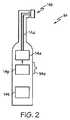
図2を参照すると、POC器具14の一実施形態が示されている。POC器具14は、アクチュエータ14a、ブラシヘッド14b、電源14p、及びスイッチ14sを有しうる。アクチュエータ14aは、駆動機構14dによってブラシヘッド14bに伝達される直線運動、回転運動、又は振動運動を発生させることができる。POC器具14内のアクチュエータ14aには、電気モータ、圧電モータ、電気化学ポリマー駆動モータ、他の任意の適当な装置、又はこれらの任意の組み合わせが含まれうる。アクチュエータ14aは、電気エネルギー(例えば、電源14pからの)を運動エネルギーに変換することによって、本明細書において述べるようにブラシヘッド14bを作動させることができる。例えば一実施形態では、アクチュエータ14aを、回転運動を発生させることが可能な回転電気モータとすることができる。アクチュエータ14aは、1以上の歯車、車軸、ベルト、駆動軸、他の適当な要素、又はこれらの任意の組み合わせを有する駆動機構14dを介してブラシヘッド14bと連結することができる。 Referring to FIG. 2, one embodiment of the
上記に述べたように、ブラシヘッド14bは、角運動、直線運動、又は曲線運動を行うことが可能であり、その運動は、アクチュエータ14aによって駆動される場合に定常的又は周期的な運動でありうる。ブラシヘッド14bは、回転のみを行うか、回転するとともにその回転軸に平行な軸に沿ってPOC器具14に出入りする運動を行うことができる。ブラシヘッド14bは使用者の歯と接触し、ブラシヘッド14bが歯と接触する際のブラシヘッド14bの運動によって、歯が掃除される。練り歯磨き又は他の適当な材料をPOC器具14と組み合わせて使用することによって、掃除プロセスの効果を高めることができる。ブラシヘッド14bは一般的に着脱可能であり、必要な場合、又は古いものが摩耗した場合に、新しいブラシヘッドと交換することができる。 As noted above, the
POC器具14は、アクチュエータ14aを作動するためのエネルギーを供給する電源14pを有している。電源14pは、POC器具14が無線で、すなわち、例えば一般的な家庭用の110ボルトのコンセントなどの別の電源につながれたワイア又はケーブルを有することなく、動作することを可能とするものである。電源14pは、例えば充電式又は非充電式電池であってよい。充電式電池は、リチウムイオン又はニッケル水素技術を用いたものでよく、非充電式電池は、アルカリ、又は亜鉛炭素技術を用いたものでよい。現在知られているもの及び開発中のものを含め、他の種類の充電式及び非充電式電池の技術を同様に使用することも可能である。電源14pは、電池以外の他の種類のエネルギー源をも含みうる。 The
POC器具14は、使用者12が作動又は停止することを可能とするスイッチ14sを有している。スイッチ14sは電源14p及びアクチュエータ14aに電気的に結合されていることにより、電源14pをアクチュエータ14aに対して接続(例えば、「オン」の場合)、又は切断(例えば、「オフ」の場合)することが可能である。スイッチ14sは、スライドスイッチ、押しボタンスイッチ、又は任意の適当な方式のスイッチであってよい。更に、POC器具は、使用者がブラシヘッドを歯に押し当てるとPOC器具14が作動するような、「自動作動」スイッチを有してもよい。使用者がPOC器具14を歯から離して圧力が解放されると、POC器具14は停止する。 The
POC器具14は、動作中に音を発生する。こうした音は、例えば、アクチュエータ14a、ブラシヘッド14b、駆動機構14d、及びスイッチ14sなどのPOC器具を構成する要素のいずれかの運動によって生じうるものである。本明細書において述べるように、駆動機構14dは、歯車及び/又は他の適当な要素を有し、その一部又は全部のものが、POC器具14が動作する際に個別に音を発生しうる。更に、音は、ブラシヘッド14bが掃除プロセスの間に歯と接触する際のブラシヘッド14bの運動によって発生しうる。したがって、POC器具14によって発生する音は、POC器具14を構成する個別の要素の一部又は全部によって発生する音の集合でありうる。 The
POC器具14は、音を発生することが可能な専用の音響装置14tを更に有してもよい。専用音響装置14tは、スピーカー、ブザー、圧電トランスデューサ、他の適当な装置、又はこれらの任意の組み合わせであってよい。専用音響装置14tの目的は、モニタリング装置(例えば、図1のモニタリング装置18)によって受信することができる、POC器具14からの情報がコードされた音を発生することでありうる。こうした情報には、例えば、POC器具14がいつ作動又は停止されるか、歯を掃除するのにPOC器具14が使用される時間の長さ、POC器具14によって歯に加えられる圧力の量、POC器具14がどの歯磨きモードにあるか、POC器具14の製造者、及び、POC器具14の型番、などが含まれる。他の種類の情報も同様にコードされうる。情報のコード化は、デジタル技術(例えば、オンオフ変調)又はアナログ技術(例えば、振幅又は周波数変調)を用いて行うことができる。例えば、専用音響装置14tはオンオフ変調を用いて、デジタル情報をモニタリング装置に送信することができる。この例では、専用音響装置14tは、高速でオン(すなわち、ロジック「1」)及びオフ(すなわち、ロジック「0」)される10kHzの音響信号を送信することによって、情報を含むデータのデジタルストリームを生成することができる。情報をコード化する他の方法を同様に使用することも可能である。 The
POC器具14が専用音響装置14tを有する場合、専用音響装置14tは、もっぱらPOC器具14に関する情報をモニタリング装置に音響的に送信するためにのみ使用することができる。すなわち、この実施形態では、モニタリング装置は、専用音響装置14tによって発生する音のみを認識することができる。別の実施形態では、モニタリング装置は、専用音響装置14tによって発生する音、及び、上記に述べたようなPOC器具14の他の要素によって発生する音の両方を認識することができる。本開示の目的においては、特に断らないかぎり、POC器具14によって発生する音には、専用音響装置14t(使用される場合)によって発生する音、及びPOC器具14の他の要素(例えば、アクチュエータ14a、ブラシヘッド14b、レフィルなど)によって発生する音が含まれる。例えば、一実施形態では、アクチュエータ14aは、例えば「スタッタリング」によってその音を改変することによって、モニタリング装置により受信することができる情報をコードした音を発生することができる。別の実施形態では、POC器具14と使用するためのブラシヘッド14bのそれぞれの部類又は種類が、新しい、又は異なるブラシヘッドが使用されていることをモニタリング装置に警告するためにモニタリング装置に送信されうる固有の音を有してもよい。一実施形態では、固有の音は使用者にとって好ましいものであってよい。別の実施形態では、固有の音は、使用者がブランドを識別することが可能なものとすることができる。 If the
再び図1を参照すると、モニタリング装置18としては、これらに限定されるものではないが、スマートフォン、携帯情報端末、ネットブック、GPS装置、タブレット、e−リーダー、iPad、携帯ゲーム機(例えば、Nintendo DS、Nintendo DSi XL、Sony PSP)、パソコン、mp3プレーヤー、iPod、又は専用のモニタリング装置が挙げられる。「スマート装置」なる用語は、1以上のソフトウェアアプリケーションを動作させることが可能な任意の携帯用装置を指す。スマート装置は、インターネット又は1以上のコンピュータネットワークに接続されてもよい。例えばモニタリング装置18には、Blackberry(登録商標)又はiPhone(登録商標)ブランドのスマートフォンが含まれうる。現在入手可能なもの及び開発中のものを含む、他の種類のモニタリング装置を同様に使用することも可能である。モニタリング装置18は、POC器具と使用するために特に開発された専用のモニタリング装置であってもよい。例えば、POC器具14及び専用のモニタリング装置を同時に開発して販売してもよい。また、モニタリング装置18を、POC器具14が使用されていないときにPOC器具14の電池を充電するための台座部に組む込むこともできる。要するに、POC器具14から発生した音を受信するように動作する多くの種類の装置を、モニタリング装置18として使用することが考えられる。モニタリング装置18は、POC器具14の特性(例えば、歯磨きの時間の長さ)を使用者12に対して表示することが可能なディスプレイ18dを有してもよい。モニタリング装置18は、使用者12が歯を磨く準備ができたという情報を使用者12がモニタリング装置18に入力するか又はモニタリング装置18に通知することを可能とする、キー18k又は他の任意の種類の入力インターフェースを有してもよい。 Referring to FIG. 1 again, the
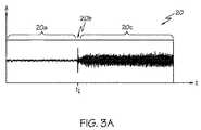
図3Aを参照すると、グラフ20は、POC器具によって発生する音を時間に対して示している。縦軸「A」は音の振幅を表し、横軸「t」は時間を表している。時間20aの間、POC器具は動作しておらず、したがってPOC器具14によって発生する音は示されていない。しかしながら、図に示されるように、わずかなバックグラウンドノイズが受信されている。本開示の目的においては、「バックグラウンドノイズ」とは、モニタリング装置によって受信されうる(すなわち、「聴かれる」)、POC器具以外の発生源から発生する音である。例えば、多くの人はバスルームで歯を磨くため、バックグラウンドノイズには、シンクに流れる水からの音、トイレを流す音、又はシャワー若しくは浴槽を流す音が含まれうる。更に、バックグラウンドノイズには、他人の会話又はラジオの音が含まれうる。モニタリング装置によって受信されるバックグラウンドノイズがない時間もありうる点は理解されるであろう。したがって、モニタリング装置によって受信される音は、POC器具によって発生する音とバックグラウンドノイズとが混ざったものでありうる。本明細書において述べるように、モニタリング装置は、受信する音を分析することによってその音の特定の音響特性を確認するように構成することができる。これにより、モニタリング装置によってPOC器具の1以上の特性を決定することが可能となる。 Referring to FIG. 3A,
引き続き図3Aを参照すると、時間20bにおいてPOC器具が作動され、この時、音の振幅に短時間のスパイク又は増大が見られる。時間20bにおけるこのスパイク又は過渡信号は、スイッチの動きによって、又はアクチュエータが動作し始める瞬間におけるアクチュエータ、駆動機構、若しくはブラシヘッドの動きによって生じうるものである。スパイクは、モニタリング装置によって検出することができる固有の周波数シグネチャを有しうる。時間20cの間、POC器具は動作しており、したがって比較的一定の振幅で音を発生している。 With continued reference to FIG. 3A, the POC instrument is activated at time 20b, when a brief spike or increase in the sound amplitude is seen. This spike or transient signal at time 20b can be caused by the movement of the switch or the movement of the actuator, drive mechanism, or brush head at the moment the actuator begins to operate. The spike may have a unique frequency signature that can be detected by the monitoring device. During time 20c, the POC instrument is operating and thus producing sound with a relatively constant amplitude.
図3Bを参照すると、グラフ22は、バックグラウンドノイズと混じったPOC器具によって発生する音を示している。縦軸「A」は音の振幅を表し、横軸「t」は時間を表している。時間22aの間では、POC器具は動作しているが、POC器具によって発生する音よりも高い振幅を有するバックグラウンドノイズが存在している(例えば、人の会話から、又は照明のスイッチを入れたり切ったりすることからの)。時間22bの間では、バックグラウンドノイズは低下し、POC器具によって発生する音がモニタリング装置によって受信される主な音となっている。したがって、モニタリング装置は、バックグラウンドノイズの振幅がPOC器具によって発生する音の振幅よりも高い場合及び低い場合の両方において、作動され、動作状態におかれているPOC器具によって発生する音の振幅の増大を測定するように構成することができる。 Referring to FIG. 3B,
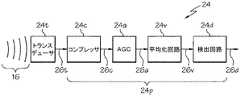
図4は、一実施形態に基づくモニタリング装置(例えば、図1のモニタリング装置18)のブロック図24を示している。モニタリング装置は、トランスデューサ24t及びプロセッサ24pを有しうる。トランスデューサ24tは、POC器具(図に示されていない)によって発生する音16を受信して、その音を、音16を表す信号26tに変換することができる。トランスデューサ24tは、マイクロフォン又は他の任意の適当な装置であってよい。この実施形態では、トランスデューサ24tは音16をアナログ信号に変換することが可能であり、この信号がプロセッサ24pに送信される。 FIG. 4 shows a block diagram 24 of a monitoring device (eg,
プロセッサ24pは、コンプレッサ24c、自動利得制御24a、平均化回路24v、及び検出回路24dを含みうる。特定の実施形態では、コンプレッサ24cはダイナミックレンジコンプレッサであってよく、比較的大きな振幅を有する瞬間的なバックグラウンドノイズを補償するように動作しうる。コンプレッサ24cは、トランスデューサからの信号26t(音を表す)を受信して圧縮信号26cを生成することにより、信号26tがコンプレッサ閾値を上回る場合に、信号26tの振幅を減衰することができる。これにより、コンプレッサ24cは、会話などのバックグラウンドノイズのスパイクを低減することができる。コンプレッサ閾値は、モニタリング装置の製造者によって設定されてもよく、あるいは、モニタリング装置が使用される場所において、較正手順(本明細書に述べる)によって使用者により設定されてもよい。一実施形態では、コンプレッサ閾値は−10dB(デシベル)でありうる。 The
コンプレッサ閾値以外に、コンプレッサ24cは、コンプレッサ24cがコンプレッサ閾値よりも低い値からそれよりも高い値に遷移する信号に反応するのに要する時間である、対応するアタックタイムを更に有しうる。同様に、コンプレッサ24cは、コンプレッサ24cがコンプレッサ閾値よりも高い値からそれよりも低い値に遷移する信号に反応するのに要する時間である、対応するリリースタイムを更に有しうる。アタックタイム及びリリースタイムはいずれも約10〜約50ミリ秒であってよく、別の実施形態では、約20〜約40ミリ秒であってよく、別の実施形態では、約25〜約35ミリ秒であってよい。一実施形態では、アタックタイムは約38ミリ秒であり、リリースタイムは約49ミリ秒でありうる。コンプレッサ24cは、信号がコンプレッサ閾値を下回る場合には、信号を減衰せずに通過させることができる。しかしながら、上記に述べたように、本明細書の特定の実施形態においては、コンプレッサ24cは、コンプレッサ閾値を上回る信号を減衰する。減衰は、線形又は非線形であってよく、コンプレッサ24cは、信号がコンプレッサ閾値をどれくらい上回るかに基づいて信号を減衰することができる。一実施形態では、信号がコンプレッサ閾値を上回る場合、減衰は約20〜30:1である。 In addition to the compressor threshold, the
自動利得制御24a(又はAGC 24a)は、圧縮信号26cを受信して、利得調整信号26aの振幅がAGCの時間長さに基づいてAGC振幅の範囲内となるような利得調整信号26aを生成する。コンプレッサ24cと比較した場合、AGC 24aは比較的長い応答時間を有しうる。一実施形態では、AGCの時間長さは、約5〜約7秒のオーダーであってよい。これは、AGC 24aは、前の5〜7秒の圧縮信号の平均振幅に基づいてその利得を調製するということである。AGC 24aは、その出力(すなわち、利得調整信号26a)の平均振幅がAGC振幅の範囲内となるように、圧縮信号を線形的に増幅又は減衰する。AGC 24aは、モニタリング装置のトランスデューサに対するPOC器具の位置に起因する、POC器具によって発生する音の弱さ又は強さを補償するうえで助けとなりうるものである。POC器具がトランスデューサから遠いほど、AGC 24aの利得は高くなる。したがって、AGC 24aは、POC器具の位置及びバックグラウンドノイズの振幅とは無関係に、比較的一定の振幅を有する利得調整信号26aを生成する。 The
平均化回路24vは、AGC 24aからの利得調整信号26aを受信し、一実施形態では約200ミリ秒でありうる平均化の時間長さに基づいて音の平均振幅26vを生成する。したがって、平均化回路24vはAGC 24aよりも速やかに反応し、これは一実施形態では約10倍速い。 The averaging
検出回路24dは、平均化回路24vによって生成された平均振幅26vを受信し、平均振幅が少なくとも最小の閾値時間長さにわたって振幅閾値を上回っているか否かを判定することにより、POC器具が作動されているか否かを判定する。一実施形態では、振幅閾値は約−108dBであり、最小の閾値時間長さは約876ミリ秒である。すなわち、プロセッサが、POC器具が作動されていると判定するためには、平均振幅26vが、少なくとも約876ミリ秒にわたって約−108dBよりも高く維持されなければならない。平均振幅26vがこの振幅閾値を常に下回る場合には、プロセッサは、POC器具が停止されていると判定する。他の実施形態では、異なる振幅閾値及び/又は最小閾値時間長さを用いることが考えられる。 The
図4に示されるモニタリング装置のブロック図24は、その要素がいずれも主としてアナログ値によって動作することからアナログ回路とみなされる。このアナログ回路は、時間的に前進し、連続するピークを探しながら音響信号を処理することができる。POC器具からの音響信号の周波数(及びこれと混ざったバックグラウンドノイズ)を使用しないことから、このアナログ回路は時間領域でも動作する。 The block diagram 24 of the monitoring device shown in FIG. 4 is regarded as an analog circuit because all of its elements operate mainly with analog values. The analog circuit can advance in time and process the acoustic signal while looking for successive peaks. This analog circuit also operates in the time domain because it does not use the frequency of the acoustic signal from the POC instrument (and the background noise mixed with it).
図4のブロック図24は、コンプレッサ24c、AGC 24a、平均化回路24v、及び検出回路24dに伝播する音を示しているが、他のトポロジーも同様に使用可能である。詳細には、AGC 24aとコンプレッサ24cの配置を変えることができる。一実施形態では、AGC 24aをコンプレッサ24cの手前に配置することができる。別の実施形態では、AGC 24aとコンプレッサ24cとが並行して動作してもよく、それぞれの出力を検出回路24dに送信される前に加え合わせることもできる。プロセッサの要素の他の配置を使用することも考えられる。 The block diagram 24 of FIG. 4 shows the sound propagating to the
モニタリング装置の動作を促進するために、トランスデューサ24t又はプロセッサ24pに他の要素を加えることもできる。例えば、トランスデューサ24tとプロセッサ24cとの間に帯域フィルタを加えることによって、POC器具によって発生する音の周波数範囲の外側のバックグラウンドノイズを除去することができる。別の例として、トランスデューサ24t又はプロセッサ24pに1以上の利得マルチプライヤを加えることによって、信号を適宜拡大縮小することができる。これには、信号を増幅すること(すなわち、利得マルチプライヤが1よりも大きい)、又は信号を減衰すること(すなわち、利得マルチプライヤが1よりも小さい)が含まれうる。例えば、平均化回路24vと検出回路24dとの間に利得マルチプライヤを加えることができる。当該技術分野において知られるような他の種類の装置又は回路をモニタリング装置に加えることも考えられる。 Other elements may be added to the
図5は、別の実施形態に基づくモニタリング装置(例えば、図1のモニタリング装置18)のブロック図28を示している。この実施形態のモニタリング装置は、トランスデューサ28t及びプロセッサ28pを有している。トランスデューサ28tは、POC器具(図に示されていない)によって発生する音16を受信して、その音を、音16を表す信号に変換することができる。トランスデューサ28tは、マイクロフォン28m及びアナログデジタル変換器28aを有しうる。マイクロフォン28mは音16を信号30mに変換し、信号30mはアナログデジタル変換器28aに送信される。アナログデジタル変換器28aは、アナログ信号(例えば、アナログ電圧信号)でありうる信号30mをデジタル信号30aに変換することができ、デジタル信号30aはプロセッサ28pに送信される。アナログデジタル変換器28aは、12ビット型、16ビット型、又は他の任意の適当な装置であってよい。デジタル信号30aは、直列又は並列信号を含みうる。例えば、アナログデジタル変換器28aは、シリアルペリフェラルインターフェース(SPI)バスの形態で直列信号をプロセッサ28pに送信することができる。他の種類の直列又は並列バスも同様に使用可能である。 FIG. 5 shows a block diagram 28 of a monitoring device (eg,
プロセッサ28pは、コンピュータ、マイクロプロセッサ、マイクロコントローラ、デジタル信号プロセッサ、又は、アナログデジタル変換器28aからデジタル信号30aを受信し、デジタル信号30aに基づいてPOC器具の1以上の特性を決定することが可能な他の任意の適当なプロセッサであってよい。この決定は、プロセッサ28pによって読み出されて実行されるコンピュータプログラムとして実施することができる。コンピュータプログラムは、プロセッサ28pに電気的に接続された記憶装置28xに保存することができる。コンピュータプログラムは、本明細書において示し、説明するアルゴリズム又は方法の1以上を実施したものである、コンピュータにより読み出し可能かつコンピュータにより実行可能な命令を含むことによって、デジタル信号30aを分析し、それに基づいてPOC器具の1以上の特性を決定することができる。 The
プロセッサ28pは、時間領域、周波数領域、又はその両方で様々なアルゴリズムを実行することが可能である。上記に述べたように、アルゴリズム(例えば、方法)は、プロセッサ28pによって実行されるコンピュータ命令として実施することができる。POC器具の1以上の特性を決定するために、プロセッサ28pが1以上のアルゴリズムを実行することも考えられる。1以上のアルゴリズムは、プロセッサによって同時、又は順次実行することができる。 The
プロセッサ28pは、記憶装置28xにデジタル信号30a(POC器具によって発生された音を表す)を保存することが可能であるため、プロセッサ28pは、現時点から過去のある時点までのデジタル信号30aの履歴を記録することができる。この履歴の長さは異なりうるものであり、例えば約10秒でありうる。すなわち、プロセッサ28pは、現時点から約10秒前の時点までのデジタル信号30aの履歴を保存することができる。この履歴は、多数のデジタル信号のサンプルを含みうる。デジタル信号30aの新しいサンプルがプロセッサ28pに送信されると、履歴の一番古いサンプルが上書きされるようにしてもよく、これにより履歴は、常に最も新しいデジタル信号30aのサンプルを有することになる。履歴の長さは、実行されるアルゴリズムの種類に基づいて、又は利用可能な記憶装置28xの量に基づいて調節することができる。プロセッサ28pによって実行されるアルゴリズムは、履歴を分析して、この履歴(言うまでもなく、POC器具によって発生する音及びあらゆるバックグラウンドノイズの履歴を表す)に基づいて、POC器具の1以上の特性を決定することが可能である。 Since the
プロセッサ28pがデジタル信号30aの一定の履歴を保存しうるため、プロセッサ28pによって実行されるアルゴリズムは、「分析時点」と呼ばれるその履歴の特定の時点を選択してデジタル信号30aを分析することができる。例えば、履歴が10秒の長さを有する場合、アルゴリズムは分析時点を現時点に設定して、過去10秒間のデジタル信号30aを分析することができる。また、アルゴリズムは、分析時点を履歴内の任意の時点に設定することができる。例えば、アルゴリズムは分析時点を5秒前に設定することが可能であり、その場合、プロセッサは分析を行うための5秒間の「履歴データ」(すなわち、10秒前から5秒前まで)と、5秒間の「未来データ」(すなわち、5秒前から現時点まで)とを有することになる。デジタル信号30aの履歴を分析するために異なるアルゴリズムがプロセッサ28pによって使用される場合には、各アルゴリズムが異なる分析時点を使用することができる。例えば、第1のアルゴリズムが現時点を分析時点として使用し、第2のアルゴリズムが2秒前の時点を分析時点として使用することができる。 Since the
分析時点を設定する以外に、プロセッサ28pによって実行されるアルゴリズムは、デジタル信号30aの履歴の連続した部分から構成されうる1以上の「時間窓」を規定することが可能であってもよい。例えば、アルゴリズムは、窓を1秒間として、すなわち、連続した1秒間のデジタル信号30aのデータとして規定することができる。履歴の長さが10秒である場合、この履歴内には10個の1秒の窓が存在する。信号に応じて、ある時間窓は相対的に過去において、ある時間窓は相対的に未来において分析されるように、分析用の基準点を選択することができる。分析時点に応じて、ある窓は過去となり(すなわち、履歴データ)、ある窓は未来となりうる(すなわち、未来データ)。本明細書において述べるように、アルゴリズムは、一連の時間窓を分析することによって、POC器具により発生された音の1以上の音響特性を確認することができる。 In addition to setting the analysis time point, the algorithm executed by the
図5のモニタリング装置は、音響信号をデジタル処理して分析することが可能なものであってよい。例えば、モニタリング装置は、音のピーク値を検出可能なもの、すなわち、時間領域で音の音響特性を測定することができるものとすることができる。しかしながら、音響信号をデジタル処理することにより、信号の個々の周波数成分を分析することも可能である。POC器具によって発生する音を分析する場合、モニタリング装置は、信号の時間的ピーク、信号の周波数成分、又はその両方を分析することが可能である。この分析では、POC器具の1以上の特性を決定するために最終的に任意の特性の組み合わせ(時間及び/又は周波数領域の)を使用することができる。 The monitoring apparatus of FIG. 5 may be capable of digitally processing and analyzing an acoustic signal. For example, the monitoring device may be capable of detecting a peak value of sound, that is, capable of measuring acoustic characteristics of sound in the time domain. However, it is also possible to analyze individual frequency components of the signal by digitally processing the acoustic signal. When analyzing the sound generated by a POC instrument, the monitoring device can analyze the temporal peak of the signal, the frequency content of the signal, or both. In this analysis, ultimately any combination of properties (in time and / or frequency domain) can be used to determine one or more properties of the POC device.
POC器具により発生する音は、それぞれが特定の周波数、振幅、及び位相(例えば、フーリエ級数)を有する別個の正弦波の和からなりうる。したがって、モニタリング装置は、離散フーリエ変換(DFT)及び/又は高速フーリエ変換(FFT)を用いて、音響信号を一連の周波数に変換することによって音響信号を分析することができる。DFT及びFFTは、プロセッサによって実行される、コンピュータにより読み出し可能かつコンピュータにより実行可能な命令(例えば、ソフトウェア)において実施されうる。DFT及びFFTを使用して音響信号を一連の別個の周波数成分に分解した後、周波数成分の相対的振幅を分析することによって、POC器具の1以上の特性を決定することができる。これには、特定の周波数又は周波数範囲の有無が含まれうる。例えば、POC器具が動作中に特定の周波数の音を常に発生する場合、この特定の周波数の存在を利用してPOC器具が動作している(すなわち、作動されている)ことを確認することができる。音響信号中の特定の周波数の有無を検出すること以外に、特定の周波数における振幅の変化も、POC器具の1以上の特性についての情報を含みうる。 The sound generated by a POC instrument can consist of a sum of separate sine waves, each having a specific frequency, amplitude, and phase (eg, Fourier series). Thus, the monitoring device can analyze the acoustic signal by converting the acoustic signal into a series of frequencies using discrete Fourier transform (DFT) and / or fast Fourier transform (FFT). DFT and FFT may be implemented in computer readable and computer executable instructions (eg, software) executed by a processor. After decomposing the acoustic signal into a series of discrete frequency components using DFT and FFT, one or more characteristics of the POC instrument can be determined by analyzing the relative amplitudes of the frequency components. This may include the presence or absence of a specific frequency or frequency range. For example, if the POC instrument always produces a sound at a specific frequency during operation, the presence of this specific frequency may be used to confirm that the POC instrument is operating (ie, activated). it can. In addition to detecting the presence or absence of a specific frequency in the acoustic signal, the change in amplitude at the specific frequency can also include information about one or more characteristics of the POC device.
また、特定の周波数処理の形態が、シグネチャ検出又はマッチングを含んでもよい。これには、周波数強度が時間とともにどのように変化したかをマッチングする(すなわち、振幅情報を抽出することにより)ことが含まれうる。検出及び分析することが可能な他の種類の音響特性としては、例えば、1)オン過渡信号のアタックタイム(例えば、ミリ秒で測定される)、2)オン過渡信号の周波数スペクトル(例えば、ヘルツで測定される)、3)速度が変動しない固定速度における安定状態アクチュエータ(例えば、モータ)の周波数スペクトル、4)ピッチ検出によって固定速度の安定状態において検出される個々に分解可能な周波数(例えば、ヘルツで測定される)、及び5)個々に分解可能な周波数の定量可能な変動又はその欠如(例えば、ヘルツで測定される)が挙げられる。上記に述べた実施例1〜4では、周波数シグネチャをマッチングすることによってPOC器具14の1以上の特性を検出することができる。上記に述べた実施例5では、周波数及び/又は振幅の変化を検出することができる。これらのアルゴリズムの1以上のものの結果を合成する(例えば、加え合わせる)ことによって、POC器具の1以上の特性を検出することができる。これら及び他の音響特性を、当該技術分野では知られるようにして分析することができる。 Also, the specific frequency processing form may include signature detection or matching. This can include matching how the frequency intensity has changed over time (ie, by extracting amplitude information). Other types of acoustic characteristics that can be detected and analyzed include, for example, 1) the attack time of the on-transient signal (eg, measured in milliseconds), 2) the frequency spectrum of the on-transient signal (eg, Hertz) 3) Frequency spectrum of a steady-state actuator (eg, motor) at a fixed speed where the speed does not fluctuate, 4) Individually decomposable frequencies (eg, And 5) quantifiable fluctuations in the frequency of individually resolvable or lack thereof (eg measured in Hertz). In Examples 1-4 described above, one or more characteristics of the
図6は、バックグラウンドノイズと混じった、POC器具によって発生する音のグラフ40を示している。縦軸「A」は音の振幅を表し、横軸「t」は時間を表している。分析するためのこの例の基準時間(信号履歴における)は、時間軸上でt=0に示されている。グラフ40は、デジタル信号の履歴としてプロセッサによって保存することができる、t=−2〜t=0までの2秒間のデジタル信号を示している。プロセッサによって実行されるアルゴリズムによって、分析時点を約1秒前(現時点に対して)でありうるt=t0に設定することができる。したがって、時間t=t0.5は、分析時点t0に対して0.5秒後であり、時間t=t−0.5は分析時点t0に対して0.5秒前でありうるが、現時点に対してはいずれも前である。FIG. 6 shows a graph 40 of the sound produced by the POC instrument mixed with background noise. The vertical axis “A” represents the amplitude of the sound, and the horizontal axis “t” represents time. The reference time (in the signal history) of this example for analysis is shown at t = 0 on the time axis. Graph 40 shows a digital signal of 2 seconds from t = −2 to t = 0 that can be saved by the processor as a history of the digital signal. Depending on the algorithm executed by the processor, the time of analysis can be set to t = t0 , which can be about 1 second ago (relative to the current time). Thus, time t = t0.5 can be 0.5 seconds after analysis time t0 and time t = t−0.5 can be 0.5 seconds before analysis time t0 . However, they are all before the current time.
図6は更に、それぞれが0.25秒の長さである4個の時間窓を示している。時間窓w−1、w−2、及びw−3は、分析時点t0に対して前にある。時間窓w1は、分析時点t0に対して後にある。本明細書において述べるように、時間窓は他の長さを有してもよく、特定のアルゴリズムが、互いとは異なりうるそれ自身の時間窓を規定してもよい。各時間窓で1以上の分析を行い、各時間窓について同じ分析を繰り返して得られた結果を、都合のよい時間にわたって後で平均化することができる。窓のサイズ(例えば、各窓当たりのサンプルの数)を変化させ、次いで複数の時間窓にわたって結果を平均化又は重み付けすることによって、検出プロセスを信号の特定の特性に対してより適合させる(すなわち、較正する)ことができる。FIG. 6 further shows four time windows that are each 0.25 seconds long. Time windows w−1 , w−2 , and w−3 are before the analysis time point t0 . Time windoww 1 is after to the analysis timet 0. As described herein, the time window may have other lengths, and a particular algorithm may define its own time window that may differ from each other. One or more analyzes can be performed in each time window, and the results obtained by repeating the same analysis for each time window can be subsequently averaged over a convenient time. By varying the size of the windows (eg, the number of samples per window) and then averaging or weighting the results over multiple time windows, the detection process is more adapted to specific characteristics of the signal (ie, Can be calibrated).
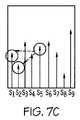
図7A〜Cは、1以上の時間窓で行うことが可能な分析の一例を示している。詳細には、図7Aは、1個の時間窓内に捕捉された多数の音サンプル(すなわち、横軸に沿ったサンプルS1〜S9)を示している。例えば、分析によって、この時間窓内の信号の平均振幅を決定することができる。これにより、システムは、特定の振幅範囲内の特定の数の連続したピークを探すことによって、信号のアタック(例えば、開始)部分を認識することが可能である。この時間窓内のいずれのサンプルも、前又は後のサンプルの振幅と比較する分析時点となりうる。例えば、図7Bは、分析時点(S5)におけるサンプルと、同じ時間窓内の後のサンプル(S8、S9)との比較を示している。同様に、図7Cは、分析時点(S5)におけるサンプルと、同じ時間窓内の前のサンプル(S1、S2)との比較を示している。この比較により、システムによってPOC器具の1以上の特性を決定することが可能となる。例えば、比較によって振幅の増加量が最小であることが示された場合、システムは、POC器具がその時間窓において作動されていると仮定することができる。他の種類の比較及び分析も同様に行うことが可能である。7A-C show an example of an analysis that can be performed over one or more time windows. Specifically, FIG. 7A shows a large number of sound samples (ie, samples S1 -S9 along the horizontal axis) captured within a single time window. For example, analysis can determine the average amplitude of the signal within this time window. This allows the system to recognize the attack (eg, start) portion of the signal by looking for a specific number of consecutive peaks within a specific amplitude range. Any sample within this time window can be an analysis time point compared to the amplitude of the previous or subsequent sample. For example, FIG. 7B shows a comparison between a sample at the time of analysis (S5 ) and a later sample (S8 , S9 ) within the same time window. Similarly, FIG. 7C shows a comparison between the sample at the time of analysis (S5 ) and the previous sample (S1 , S2 ) within the same time window. This comparison allows the system to determine one or more characteristics of the POC appliance. For example, if the comparison indicates that the amount of increase in amplitude is minimal, the system can assume that the POC appliance is operating in that time window. Other types of comparisons and analyzes can be performed as well.
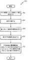
図8は、POC器具の1以上の特性を決定するための方法の一実施形態のフロー図50を示している。この方法は、図5に示し、本明細書において述べるようなプロセッサ上で実行することができる。方法は、任意の適当な順序で行いうる多数の工程を含みうる。方法の工程52では、POC器具によって発生された音を受信することを行う。これには、バックグラウンドノイズも含まれうる。方法の工程54では、例えば時間領域及び/又は周波数領域の特性などの音の1以上の音響特性を特定することを行う。更に、方法の工程56では、音の1以上の音響特性に基づいてPOC器具の1以上の特性を決定することを行う。図5に関して述べたように、方法は、プロセッサによって読み出し及び実行される、コンピュータにより読み出し可能及びコンピュータにより実行可能な命令として実施されうる。方法には、当該技術分野では周知のソフトウェアアルゴリズム及びサブルーチンが含まれうる。 FIG. 8 shows a flow diagram 50 of one embodiment of a method for determining one or more characteristics of a POC device. This method can be performed on a processor as shown in FIG. 5 and described herein. The method can include a number of steps that can be performed in any suitable order. In method step 52, the sound generated by the POC appliance is received. This can also include background noise. In
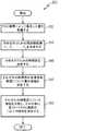
図9は、POC器具の1以上の特性を決定するための方法の別の実施形態のフロー図60を示している。この方法は、図4のブロック図と似たものであり、音の時間的特性のみに依存していることから、時間領域アルゴリズムとして実行することができる。図9のフロー図60は、増幅器などを使用して(アナログ)ハードウェアにおいて実行される多くの工程を含みうる。フロー図60は、図5に示されるようなプロセッサによって読み出し及び実行される、コンピュータにより読み出し可能及びコンピュータにより実行可能な命令として実施することもできる。方法の工程62では、POC器具によって発生した音を受信することを行う。これには、バックグラウンドノイズも含まれうる。方法の工程64では、音の振幅がコンプレッサ閾値を上回る場合に音の振幅が減衰されるように、音を圧縮することを行う。方法の工程66では、音に対して自動利得制御(AGC)機能を行う。この工程では、AGCの時間長さに基づいてAGC振幅の範囲内となるように音の振幅を調整する。方法の工程68では、一実施形態では200ミリ秒でありうる、平均化の時間長さに基づいて、平均の音の振幅を決定することを行う。最後に、方法の工程70では、平均振幅が所定の振幅閾値を少なくとも最小の閾値時間長さにわたって上回るか否かを判定することによって、POC器具が作動されているか否かを判定することを行う。 FIG. 9 shows a flow diagram 60 of another embodiment of a method for determining one or more characteristics of a POC device. This method is similar to the block diagram of FIG. 4 and depends only on the temporal characteristics of the sound and can therefore be implemented as a time domain algorithm. The flow diagram 60 of FIG. 9 may include many steps performed in (analog) hardware using an amplifier or the like. Flow diagram 60 may also be implemented as computer readable and computer executable instructions read and executed by a processor as shown in FIG. In method step 62, the sound generated by the POC device is received. This can also include background noise. In
図10は、POC器具の1以上の特性を決定するための方法の更なる別の実施形態のフロー図80を示している。この方法は、音の周波数的な特性を分析するものであるため、周波数領域アルゴリズムとみなすことができる。図10のフロー図80は、プロセッサによって読み出し及び実行される、コンピュータにより読み出し可能及びコンピュータにより実行可能な命令として実施することができる。フロー図80は、任意の適当な順序で行いうる多数の工程を含みうる。方法の工程82では、POC器具によって発生された音を受信することを行う。これにはバックグラウンドノイズも含まれうる。方法の工程84では、後で分析される周波数成分又は値を決定することを行う。所定の範囲の周波数が、F1,F2,...,FNとして示され、ただしF1はこの範囲内の第1の周波数であり、F2はこの範囲内の第2の周波数である、といった要領である。各周波数範囲(及びその周波数の組)は固有のものであり、周波数範囲同士は重なり合いうる。例えば、ある周波数範囲は約1000Hz〜約1200Hzでありうる。別の周波数範囲は約800Hz〜約900Hzでありうる。これらの周波数範囲は、POC器具によって発生する音の周波数に基づいて決定することができる。本明細書において述べられるように、POC器具によって発生する音はPOC器具の異なる要素によって発生されうることから、音は異なる周波数を有しうる。FIG. 10 shows a flow diagram 80 of yet another embodiment of a method for determining one or more characteristics of a POC device. Since this method analyzes the frequency characteristics of sound, it can be regarded as a frequency domain algorithm. The flow diagram 80 of FIG. 10 may be implemented as computer-readable and computer-executable instructions that are read and executed by a processor. Flow diagram 80 may include a number of steps that may be performed in any suitable order. In method step 82, the sound generated by the POC device is received. This may include background noise. In
方法の工程86では、後に分析される時間窓を決定することを行う。本明細書において述べられるように、モニタリング装置は、POC器具によって発生する音(バックグラウンドノイズを含む)を表すデジタル信号の過去の履歴を記録及び保存することが可能であり、この履歴を、個々に分析することが可能な一連の時間窓に分割することができる。例えば、過去10秒間の履歴を保存し、これを10個の1秒の時間窓、20個の0.5秒の時間窓、又は他の任意の適当な数の時間窓に分割することができる。
方法の工程88では、それぞれの時間窓の各周波数範囲について音の振幅を決定することを行う。したがって、N個の周波数範囲がある場合、それぞれの時間窓についてN個の振幅が存在することになる。この工程では、それぞれの時間窓についてDFT又はFFTを行うことができる。最後に、方法の工程90では、それぞれの時間窓についてN個の振幅を分析し、その分析に基づいてPOC器具の1以上の特性を決定することを行う。例えば、POC器具が作動されているか否かを判定するため、分析は、F1の周波数範囲の振幅が下側閾値から上側閾値に少なくとも最小の時間長さにわたって増大したか否かに基づいたものとすることができる。他の分析は、1以上の周波数範囲の振幅の変化に基づいたものとすることができる。分析を、1以上の周波数範囲において特定の振幅(例えば、閾値を下回る振幅)が存在しないことに基づいたものとすることも考えられる。In
再び図1を参照すると、モニタリング装置18及びPOC器具14が使用される音響環境は大きく変動しうる。例えば、バスルームは多くの人が歯を磨く場所であることから、モニタリング装置18はバスルームで使用されうる。バスルームの音響環境は、とりわけバスルームのサイズ、壁の構造及び配置、並びにバスルーム内に存在する物品(例えば、ラグ、装飾品、及びカーテン)の種類及び配置に依存しうる。更に、モニタリング装置がPOC器具から見て配置される距離も関係する。POC器具がモニタリング装置に近いほど、POC器具はバックグラウンドノイズと比較して強い音を発生する。最後に、バックグラウンドノイズは音響環境にも寄与しうる。これらの因子を補償し、モニタリング装置18の動作を改善するためには、較正手順を用いて、例えば、図4に示され、本明細書に述べられるようなコンプレッサのコンプレッサ閾値の値などのモニタリング装置のパラメータの一部又はすべてを設定することができる。例えば、アナログ又はデジタル処理を行うための利得、感度、閾値、及び、床面でのノイズレベルなどの他のハードウェア及び/又はソフトウェアのパラメータを設定することもできる。 Referring again to FIG. 1, the acoustic environment in which the
このような較正手順は比較的単純であり、一度行うのみでよい(例えば、POC器具14及びモニタリング装置18が最初に使用に供されるとき)。較正手順の一例としては以下のようなものがある。第1に、モニタリング装置18を、トランスデューサ(例えば、マイクロフォン)がPOC器具の方向を向くようにして安定した表面の上に置く。トランスデューサはPOC器具の高さにできるだけ近くすることが好ましいが、トランスデューサは通常は全方向のピックアップパターンを有していることから必須ではない。第2に、POC器具を回転させ、トランスデューサから一定の距離に短時間の間(例えば、10秒間)保持する。一般的には、この時点で顕著な、又は大きな他のバックグラウンドノイズは存在しないはずである。そして第3に、POC器具を停止させた状態で、バックグラウンドノイズのみ(他の大きな音がない状態で)を短時間(例えば、約10秒間)サンプリングする。この工程により、モニタリング装置18が、モニタリング装置のノイズ(例えば、トランスデューサ、フィルタ、アナログデジタル変換など)と室内のバックグラウンドノイズを組み合わせた有効複合ノイズを測定することが可能となる。これらの較正工程により、モニタリング装置18が、モニタリング装置18が使用される室内の音響特性に基づいてパラメータを調整することが可能となる。これらのパラメータは、モニタリング装置18の記憶装置に保存して、POC器具の1以上の特性を決定するためにモニタリング装置18が使用される際に、後で使用することができる。 Such a calibration procedure is relatively simple and only needs to be performed once (eg, when the
較正手順において、モニタリング装置18が1以上のパラメータを調整することによって、POC器具によって発生する音の音響特性を検出するために使用される要素(すなわち、ハードウェア又はソフトウェア)の動作を向上させることができる。例えば、モニタリング装置18の実施形態がコンプレッサを使用している場合、較正手順においてコンプレッサ閾値、コンプレッサ比、アタックタイム、及び/又はリリースタイムを調整することによってコンプレッサの動作を向上させることができる。これらのパラメータは、同時又は順次調整することができる。同様に、モニタリング装置18が自動利得制御(AGC)回路を使用している場合には、較正手順において立ち上がり時間又はAGC振幅の範囲を調整することによってAGC回路の動作を向上させることができる。 In the calibration procedure, the
モニタリング装置18の実施形態が周波数領域のアルゴリズムを使用している場合には、較正手順によってモニタリング装置18がPOC器具及びバックグラウンドノイズの周波数特性を捕捉することが可能となりうる。これにより、モニタリング装置18は、後でPOC器具の特性を決定する際に、対象とする周波数(すなわち、POC器具によって発生する音の周波数)を分析する一方で他の周波数(すなわち、バックグラウンドノイズの周波数)は無視することができる。 If an embodiment of the
引き続き図1を参照し、POC器具14及びモニタリング装置18の一般的な動作を次に説明する。使用者12がPOC器具14を使用する準備が整った時点で、使用者12は近くにモニタリング装置18を配置することができる。また、モニタリング装置18は、POC器具14によって発生する音を適当に監視するための適正な位置に予め配置されてもよい。次いで使用者12は、モニタリング装置18にPOC器具14を使用する準備が整ったことを通知することができる。これは、例えばモニタリング装置18上の1以上のキー18k又は他の種類の入力インターフェースを押すことによって行うことができる。代替手段として、使用者の声を認識するようにモニタリング装置18をプログラムし、使用者12が単語又はフレーズ(例えば、「スタート」)を発語することによってこのタスクが行われるようにすることもできる。別の実施形態では、使用者12がPOC器具を「作動」させ、モニタリング装置18がPOC器具14によって発生する音を認識して「起動」する(すなわち、使用者12が歯磨きを開始するとモニタリング装置18が「起動」する)。 With continued reference to FIG. 1, the general operation of the
モニタリング装置18に使用者12が歯を磨く準備が整ったことが知らされた時点で、使用者12は、POC器具14を手に取って歯磨きを開始することができる。次いでモニタリング装置18は、POC器具14によって発生された音を受信し、POC器具14によって発生したその音を用いて、POC器具14の1以上の特性を決定することができる。POC器具14によって発生する音には、本明細書において述べられるように、その機械的部品(例えば、アクチュエータ、ブラシヘッドなど)によって発生する音、専用の音響装置によって発生する音、又はこれらの組み合わせが含まれうる。やはり本明細書において述べられるように、こうした特性には、POC器具が使用される時間の長さ、使用者12によって歯に加えられる圧力の大きさなどが含まれうる。 When the
使用者12が歯を磨き終わり、モニタリング装置18が(その特定の歯磨き作業について)POC器具14の1以上の特性を決定した後、モニタリング装置18がこれらの特性を記憶装置に保存することができる。モニタリング装置18は長期(例えば、1ヶ月、3ヶ月、1年、など)にわたって特性を保存できることから、使用者の歯ブラシの癖の履歴が維持される。使用者12又は使用者の口腔ケアの専門家(例えば、歯科医)がこの履歴を利用して、使用者12が適切に歯を磨いているか否かを確認することができる。この履歴に基づいて、使用者12が歯磨きの癖を改善することによって、虫歯及び他の口腔(例えば、口)又は組織(例えば、歯肉及び歯)の問題を予防することができる。モニタリング装置18は更に、使用者12が特性を直ちに見ることができるように、特性をモニタリング装置18のディスプレイ18dに表示することもできる。モニタリング装置18は、歯磨きの癖及び/又はPOC器具14自体に関する勧告を使用者12に対して行うこともできる。例えば、モニタリング装置18は、POC器具14によって発生する音の音響特性に基づいて、又はブラシヘッドが最後にいつ交換されたかについての使用者の入力(例えば、キー18kを介した)に基づいて、歯ブラシをより頻繁に行うこと、又はブラシヘッドを交換することを勧告することができる。別の例として、モニタリング装置18は、POC器具の電池の交換がいつ必要となるかを決定することができる。 After the
本明細書に開示される寸法及び値は、記載される数値そのものに厳密に限定されるものと理解すべきでない。むしろ、特に断らないかぎり、そのようなそれぞれの寸法は、記載された値及びその値の周辺の機能的に同等の範囲の両方を意味するものとする。例えば「40mm」として開示される寸法は、「約40mm」を意味するものとする。 The dimensions and values disclosed herein are not to be understood as being strictly limited to the numerical values recited. Rather, unless otherwise specified, each such dimension is intended to mean both the recited value and a functionally equivalent range surrounding that value. For example, a dimension disclosed as “40 mm” shall mean “about 40 mm”.
相互参照されるか又は関連するすべての特許若しくは特許出願を含む、本願に引用されるすべての文書を、特に除外すること又は限定することを明言しないかぎりにおいて、その全容にわたって本願に援用するものである。いずれの文献の引用も、こうした文献が本願で開示又は特許請求されるすべての発明に対する先行技術であることを容認するものではなく、また、こうした文献が、単独で、あるいは他のすべての参照文献とのあらゆる組み合わせにおいて、こうした発明のいずれかを参照、教示、示唆又は開示していることを容認するものでもない。更に、本文書における用語のいずれかの意味又は定義が、援用される文書における同じ用語のいずれかの意味又は定義と矛盾する場合、本文書において用語に与えられた意味又は定義が優先するものとする。 All documents cited in this application, including all cross-referenced or related patents or patent applications, are hereby incorporated by reference in their entirety, unless expressly stated to be excluded or limited. is there. Citation of any document is not an admission that such document is prior art to all inventions disclosed or claimed in this application, and such document alone or all other references. And no reference to, teaching, suggestion, or disclosure of any such invention in any combination thereof. Further, if any meaning or definition of a term in this document conflicts with any meaning or definition of the same term in the incorporated document, the meaning or definition given to the term in this document shall prevail. To do.
以上、本発明の特定の実施形態を例示、説明したが、他の様々な変更及び修正を本発明の趣旨及び範囲から逸脱することなく実施しうる点は当業者には明白であろう。したがって、本発明の範囲に含まれるそのような変更及び改変はすべて、添付の特許請求の範囲において網羅するものとする。 While specific embodiments of the invention have been illustrated and described, it will be apparent to those skilled in the art that various other changes and modifications can be made without departing from the spirit and scope of the invention. Accordingly, all such changes and modifications within the scope of this invention are intended to be covered by the appended claims.
Claims (3)
Translated fromJapanese前記トランスデューサ(24t)は、前記電動口腔ケア(POC)器具(14)によって発生する音(16)を受信して、前記音(16)を、前記音(16)を表す信号に変換し、
前記トランスデューサ(24t)は、前記プロセッサ(28p)と電気的通信状態にあり、前記音(16)を表す前記信号を前記プロセッサ(28p)に送信し、
前記プロセッサ(28p)は、前記音(16)を表す前記信号に基づいて前記電動口腔ケア(POC)器具(14)の1以上の特性を決定し、
前記装置(18)が、スマート装置又は専用のモニタリング装置であり、
前記トランスデューサ(24t)がマイクロフォン(28m)を含み、前記信号がアナログ信号を含み、
前記プロセッサ(28p)は、コンプレッサ(24c)、自動利得制御(AGC)(24a)、平均化回路(24v)、及び検出回路(24d)を含み、
前記コンプレッサ(24c)は、前記音(16)を表す前記信号を受信して、前記信号の振幅がコンプレッサ(24c)閾値を上回る場合に前記信号の振幅を減衰するような圧縮信号を生成し、
前記AGC(24a)は、前記圧縮信号を受信して、利得調整信号の振幅がAGC(24a)の時間長さに基づいてAGC(24a)振幅の範囲内となるような利得調整信号を生成し、
前記平均化回路(24v)は、前記利得調整信号を受信して、平均化の時間長さに基づいて前記音(16)の平均振幅を決定し、
前記検出回路(24d)は、前記平均振幅を受信して、前記平均振幅が少なくとも最小の閾値時間長さにわたって振幅閾値を上回っているか否かを判定することにより、前記電動口腔ケア(POC)器具(14)が作動されているか否かを判定し、
前記トランスデューサ(24t)はマイクロフォン(28m)及びアナログデジタル変換器(28a)を含み、前記プロセッサ(28p)はマイクロプロセッサを含み、
前記マイクロフォン(28m)は、前記電動口腔ケア(POC)器具(14)によって発生する前記音(16)を受信して、前記音(16)を、前記音(16)を表すアナログ信号(30m)に変換し、前記アナログ信号(30m)を前記アナログデジタル変換器(28a)に送信し、
前記アナログデジタル変換器(28a)は、前記アナログ信号(30m)をデジタル信号(30a)に変換し、前記デジタル信号(30a)を前記マイクロプロセッサに送信し、
前記マイクロプロセッサは、前記デジタル信号(30a)に基づいて前記電動口腔ケア(POC)器具(14)の前記1以上の特性を決定する、装置(18)。A monitoring device (18) for acoustically determining one or more characteristics of a powered oral care (POC) device (14) comprising a transducer (24t) and a processor (28p);
The transducer (24t) receives sound (16) generated by the powered oral care (POC) device (14) and converts the sound (16) into a signal representative of the sound (16);
The transducer (24t) is in electrical communication with the processor (28p) and transmits the signal representing the sound (16) to the processor (28p);
The processor (28p) determines one or more characteristics of the powered oral care (POC) device (14) based on the signal representing the sound (16);
The device (18) is a smart device or a dedicated monitoring device;
The transducer (24t) includes a microphone (28m), and the signal includes an analog signal;
The processor (28p) includes a compressor (24c), an automatic gain control (AGC) (24a), an averaging circuit (24v), and a detection circuit (24d),
The compressor (24c) receives the signal representing the sound (16) and generates a compressed signal that attenuates the amplitude of the signal when the amplitude of the signal exceeds a compressor (24c) threshold;
The AGC (24a)receives the compressedsignal, the amplitude of thegain adjustment signal to generate a gain adjustment signal such that the AGC (24a) within the range of the amplitude based on the time length of the AGC (24a) ,
The averaging circuit (24v) receives the gain adjustment signal, determines an average amplitude of the sound (16) based on an averaging time length,
The detection circuit (24d) receives the average amplitude and determines whether the average amplitude has exceeded an amplitude threshold for at least a minimum threshold time length, thereby enabling the powered oral care (POC) device Determine whether (14) is activated,
The transducer (24t) includes a microphone (28m) and an analog-digital converter (28a), and the processor (28p) includes a microprocessor,
The microphone (28m) receives the sound (16) generated by the powered oral care (POC) device (14) and converts the sound (16) into an analog signal (30m) representing the sound (16). To the analog signal (30m) to the analog-digital converter (28a),
The analog-digital converter (28a) converts the analog signal (30m) into a digital signal (30a), and transmits the digital signal (30a) to the microprocessor,
The microprocessor (18), wherein the microprocessor determines the one or more characteristics of the powered oral care (POC) device (14) based on the digital signal (30a).
前記電動口腔ケア(POC)器具(14)が作動されているか又は停止されているか、 前記電動口腔ケア(POC)器具(14)が歯を掃除するために使用される時間(20c)の長さ、
前記電動口腔ケア(POC)器具(14)によって歯に加えられる接触圧力、
前記電動口腔ケア(POC)器具(14)の製造者、
前記電動口腔ケア(POC)器具(14)の型番、及び
前記電動口腔ケア(POC)器具(14)の歯磨きモード、からなる群から選択される少なくとも1つを含む、請求項1に記載の装置(18)。The one or more characteristics of the electric oral care (POC) device (14) are:
Whether the electric oral care (POC) device (14) is activated or stopped, or the length of time (20c) that the electric oral care (POC) device (14) is used to clean teeth ,
Contact pressure applied to teeth by the electric oral care (POC) device (14);
A manufacturer of the electric oral care (POC) device (14);
The apparatus of claim 1, comprising at least one selected from the group consisting of a model number of the electric oral care (POC) device (14) and a brushing mode of the electric oral care (POC) device (14). (18).
Applications Claiming Priority (3)
| Application Number | Priority Date | Filing Date | Title |
|---|---|---|---|
| US12/787,637 | 2010-05-26 | ||
| US12/787,637US20110294096A1 (en) | 2010-05-26 | 2010-05-26 | Acoustic Monitoring of Oral Care Devices |
| PCT/US2011/037328WO2011149776A1 (en) | 2010-05-26 | 2011-05-20 | Acoustic monitoring of oral care devices |
Publications (2)
| Publication Number | Publication Date |
|---|---|
| JP2013526379A JP2013526379A (en) | 2013-06-24 |
| JP5646739B2true JP5646739B2 (en) | 2014-12-24 |
Family
ID=44541346
Family Applications (1)
| Application Number | Title | Priority Date | Filing Date |
|---|---|---|---|
| JP2013511384AExpired - Fee RelatedJP5646739B2 (en) | 2010-05-26 | 2011-05-20 | Acoustic monitoring of oral care devices |
Country Status (7)
| Country | Link |
|---|---|
| US (1) | US20110294096A1 (en) |
| EP (1) | EP2575538A1 (en) |
| JP (1) | JP5646739B2 (en) |
| KR (1) | KR101495977B1 (en) |
| CN (1) | CN102905578B (en) |
| AU (1) | AU2011258648B8 (en) |
| WO (1) | WO2011149776A1 (en) |
Families Citing this family (27)
| Publication number | Priority date | Publication date | Assignee | Title |
|---|---|---|---|---|
| US9022961B2 (en)* | 2009-07-30 | 2015-05-05 | Mcneil-Ppc., Inc. | Oral care cleaning and treating device |
| US8617090B2 (en) | 2009-07-30 | 2013-12-31 | Mcneil-Ppc, Inc. | Oral care device |
| US9022960B2 (en) | 2009-07-30 | 2015-05-05 | Mcneil-Ppc, Inc. | Oral care cleaning and treating device |
| MX343473B (en) | 2010-05-28 | 2016-11-07 | Solarcity Corp | Heliostat repositioning system and method. |
| US9308064B2 (en)* | 2010-07-26 | 2016-04-12 | Johnson & Johnson Consumer Inc. | Devices and methods for collecting and analyzing fluid samples from the oral cavity |
| US8442790B2 (en) | 2010-12-03 | 2013-05-14 | Qbotix, Inc. | Robotic heliostat calibration system and method |
| US9121927B2 (en) | 2012-05-29 | 2015-09-01 | Qbotix, Inc. | Acoustic absolute position encoder and method |
| JP6136595B2 (en)* | 2013-06-04 | 2017-05-31 | 株式会社ジェイテクト | Actuator control device |
| US9750586B2 (en) | 2013-07-09 | 2017-09-05 | Xiusolution Co., Ltd. | Attachable toothbrush'S posture or movement tracking device |
| CN104284275B (en)* | 2013-07-12 | 2018-10-09 | 钰太芯微电子科技(上海)有限公司 | A kind of microphone array system of super low noise high amplitude audio capturing |
| CN104783915B (en)* | 2015-03-30 | 2017-01-04 | 苏州锟恩电子科技有限公司 | A kind of Intelligent toothbrush |
| CN104783917B (en)* | 2015-03-30 | 2017-01-04 | 苏州锟恩电子科技有限公司 | A kind of intelligence oral cavity cleaning device |
| US20170206804A1 (en)* | 2015-09-17 | 2017-07-20 | Funbrush Ltd. | Interactive add-on device for kids for a toothbrush and a platform for mobile devices containing games controlled by that device |
| WO2017168301A1 (en)* | 2016-03-30 | 2017-10-05 | Koninklijke Philips N.V. | Methods and systems for calibrating an oral cleaning device |
| US10588400B2 (en)* | 2016-06-27 | 2020-03-17 | L'oreal | System to promote optimum performance of handheld cosmetic device |
| CN106175961A (en)* | 2016-08-05 | 2016-12-07 | 深圳易加仁技术有限公司 | Connector and apparatus for cleaning oral cavity |
| JP7394622B2 (en) | 2016-11-09 | 2023-12-08 | コーニンクレッカ フィリップス エヌ ヴェ | Network for collaborative personal care devices |
| US10835028B2 (en) | 2016-11-14 | 2020-11-17 | Colgate-Palmolive Company | Oral care system and method |
| US11043141B2 (en) | 2016-11-14 | 2021-06-22 | Colgate-Palmolive Company | Oral care system and method |
| US11361672B2 (en) | 2016-11-14 | 2022-06-14 | Colgate-Palmolive Company | Oral care system and method |
| US11213120B2 (en) | 2016-11-14 | 2022-01-04 | Colgate-Palmolive Company | Oral care system and method |
| US10582764B2 (en) | 2016-11-14 | 2020-03-10 | Colgate-Palmolive Company | Oral care system and method |
| IT201800004978A1 (en) | 2018-04-30 | 2019-10-30 | Electric toothbrush. | |
| US11622751B2 (en) | 2018-12-19 | 2023-04-11 | Johnson & Johnson Consumer Inc. | Devices and methods for collecting saliva samples from the oral cavity |
| US12357080B2 (en)* | 2019-06-21 | 2025-07-15 | The Research Foundation For The State University Of New York | System and method for toothbrush monitoring using magneto-inductive coil sensor |
| JP7478981B2 (en)* | 2019-10-10 | 2024-05-08 | パナソニックIpマネジメント株式会社 | Status detection device, status detection system, and status detection program |
| CN111281589B (en)* | 2020-01-22 | 2021-12-28 | 京东方科技集团股份有限公司 | Tooth brushing guidance method and device and toothbrush |
Family Cites Families (17)
| Publication number | Priority date | Publication date | Assignee | Title |
|---|---|---|---|---|
| US6314380B1 (en)* | 1999-06-03 | 2001-11-06 | Robert Bosch Corporation Corp Of Delaware | Ultrasound transducer temperature compensation methods, apparatus and programs |
| US6199239B1 (en)* | 1999-09-01 | 2001-03-13 | Herbert A. Dickerson | Toothbrush with audible reminder mechanism |
| US20030084527A1 (en) | 2001-11-06 | 2003-05-08 | The Procter & Gamble Co. | Multi-motion toothbrush |
| DE10154946A1 (en)* | 2001-11-08 | 2003-05-22 | P A T Ges Zur Foerderung Innov | Appliance for cleaning teeth has a gripping part with movement sensors to detect movement patterns in a cleaning process and a cleaning part with an interchangeable brush head. |
| US7202941B2 (en)* | 2002-11-26 | 2007-04-10 | Munro James F | Apparatus for high accuracy distance and velocity measurement and methods thereof |
| CA2545009C (en)* | 2003-11-24 | 2013-11-12 | Widex A/S | Hearing aid and a method of noise reduction |
| US7845041B2 (en)* | 2005-05-03 | 2010-12-07 | Colgate-Palmolive Company | Interactive musical toothbrush |
| US20080209650A1 (en)* | 2005-05-03 | 2008-09-04 | Ultreo, Inc. | Oral hygiene devices |
| US20070071541A1 (en)* | 2005-06-15 | 2007-03-29 | Luis Vila | Electronic toothbrush |
| US7748069B2 (en)* | 2005-12-15 | 2010-07-06 | Cynthia A Dawley | Multimedia toothbrush (toothpix) |
| US8075315B2 (en)* | 2006-12-13 | 2011-12-13 | Colgate-Palmolive Company | Oral care implement having user-interactive display |
| US8137109B2 (en)* | 2006-12-13 | 2012-03-20 | Colgate-Palmolive Company | Interactive oral care implement system |
| US8201295B2 (en)* | 2007-02-16 | 2012-06-19 | Colgate-Palmolive Company | Oral care implement having user-interactive display and moving head |
| US8375133B2 (en)* | 2007-08-07 | 2013-02-12 | Sony Computer Entertainment Inc. | Methods and apparatuses for synchronizing and managing content over multiple devices |
| US8159352B2 (en)* | 2007-09-11 | 2012-04-17 | Colgate-Palmolive Company | Personal care implement having a display |
| NO327674B1 (en)* | 2007-09-12 | 2009-09-07 | Det Norske Veritas As | Device for detecting moisture penetration in an insulation layer by means of acoustic resonance technology |
| US20090241278A1 (en)* | 2008-04-01 | 2009-10-01 | Marc Lemchen | Apparatus And Method For Monitoring Dental Brushing Performance With A Conventionally Manufactured Toothbrush |
- 2010
- 2010-05-26USUS12/787,637patent/US20110294096A1/ennot_activeAbandoned
- 2011
- 2011-05-20AUAU2011258648Apatent/AU2011258648B8/ennot_activeCeased
- 2011-05-20EPEP11728094.1Apatent/EP2575538A1/ennot_activeWithdrawn
- 2011-05-20WOPCT/US2011/037328patent/WO2011149776A1/enactiveApplication Filing
- 2011-05-20JPJP2013511384Apatent/JP5646739B2/ennot_activeExpired - Fee Related
- 2011-05-20KRKR1020127031200Apatent/KR101495977B1/ennot_activeExpired - Fee Related
- 2011-05-20CNCN201180025613.5Apatent/CN102905578B/ennot_activeExpired - Fee Related
Also Published As
| Publication number | Publication date |
|---|---|
| AU2011258648A8 (en) | 2015-08-06 |
| WO2011149776A1 (en) | 2011-12-01 |
| JP2013526379A (en) | 2013-06-24 |
| KR20130014690A (en) | 2013-02-08 |
| AU2011258648A1 (en) | 2012-12-20 |
| CN102905578B (en) | 2016-01-20 |
| US20110294096A1 (en) | 2011-12-01 |
| EP2575538A1 (en) | 2013-04-10 |
| KR101495977B1 (en) | 2015-02-25 |
| AU2011258648B2 (en) | 2015-03-19 |
| AU2011258648B8 (en) | 2015-08-06 |
| CN102905578A (en) | 2013-01-30 |
Similar Documents
| Publication | Publication Date | Title |
|---|---|---|
| JP5646739B2 (en) | Acoustic monitoring of oral care devices | |
| US12295486B2 (en) | Toothbrush system with sensors for a dental hygiene monitoring system | |
| CN111902101B (en) | Toothbrush system | |
| JP5951767B2 (en) | Personal care device | |
| CN107072388B (en) | System and method for providing motivational feedback to a user prior to brushing | |
| EP2616002B1 (en) | Toothbrush usage monitoring | |
| JP2005244968A5 (en) | ||
| RU2011100170A (en) | INTERACTIVE TOOTHBRUSH | |
| CN105455911A (en) | Control method and device of intelligent electric toothbrush | |
| KR20110005720A (en) | Interactive toothbrush and removable audio output module | |
| RU2731228C2 (en) | Methods and systems for optical perception of forces in toothbrush | |
| JP7241015B2 (en) | Methods and systems for localization of personal care devices | |
| JP2019509841A (en) | Method and system for calibrating an oral cleaning device | |
| US20230206745A1 (en) | System for Reminding a User to Brush the User's Teeth | |
| CN108261127B (en) | Control method and system of skin beauty instrument | |
| CN114007544A (en) | System for determining brushing angle of oral care device | |
| CN114502928A (en) | State detection device, state detection system, and state detection program | |
| CN114598950A (en) | Bone conduction overpressure reminder device and method | |
| CN116236306B (en) | Control method and device of electric toothbrush and electric toothbrush | |
| CN113116579A (en) | Electric tooth brush | |
| TW201809932A (en) | Multifunctional bathroom mirror box system | |
| CN116743026A (en) | Electric toothbrush noise reduction control system, method and electric toothbrush | |
| CN119766064A (en) | A method and device for adaptively adjusting a motor of an electric toothbrush | |
| CN110664110A (en) | Dental plaque monitoring method, monitoring device, monitoring system, storage device and toothbrush | |
| CN116741125A (en) | Electric toothbrush sound effect control system, method and electric toothbrush |
Legal Events
| Date | Code | Title | Description |
|---|---|---|---|
| A977 | Report on retrieval | Free format text:JAPANESE INTERMEDIATE CODE: A971007 Effective date:20131212 | |
| A131 | Notification of reasons for refusal | Free format text:JAPANESE INTERMEDIATE CODE: A131 Effective date:20140131 | |
| A601 | Written request for extension of time | Free format text:JAPANESE INTERMEDIATE CODE: A601 Effective date:20140430 | |
| A602 | Written permission of extension of time | Free format text:JAPANESE INTERMEDIATE CODE: A602 Effective date:20140509 | |
| A521 | Request for written amendment filed | Free format text:JAPANESE INTERMEDIATE CODE: A523 Effective date:20140520 | |
| A131 | Notification of reasons for refusal | Free format text:JAPANESE INTERMEDIATE CODE: A131 Effective date:20140822 | |
| A521 | Request for written amendment filed | Free format text:JAPANESE INTERMEDIATE CODE: A523 Effective date:20140916 | |
| TRDD | Decision of grant or rejection written | ||
| A01 | Written decision to grant a patent or to grant a registration (utility model) | Free format text:JAPANESE INTERMEDIATE CODE: A01 Effective date:20141010 | |
| A61 | First payment of annual fees (during grant procedure) | Free format text:JAPANESE INTERMEDIATE CODE: A61 Effective date:20141105 | |
| R150 | Certificate of patent or registration of utility model | Ref document number:5646739 Country of ref document:JP Free format text:JAPANESE INTERMEDIATE CODE: R150 | |
| R250 | Receipt of annual fees | Free format text:JAPANESE INTERMEDIATE CODE: R250 | |
| S111 | Request for change of ownership or part of ownership | Free format text:JAPANESE INTERMEDIATE CODE: R313111 | |
| R350 | Written notification of registration of transfer | Free format text:JAPANESE INTERMEDIATE CODE: R350 | |
| LAPS | Cancellation because of no payment of annual fees |