JP5646487B2 - Prosthesis comprising a knitted assembly and method for producing a prosthesis by sonic welding - Google Patents
Prosthesis comprising a knitted assembly and method for producing a prosthesis by sonic weldingDownload PDFInfo
- Publication number
- JP5646487B2 JP5646487B2JP2011526593AJP2011526593AJP5646487B2JP 5646487 B2JP5646487 B2JP 5646487B2JP 2011526593 AJP2011526593 AJP 2011526593AJP 2011526593 AJP2011526593 AJP 2011526593AJP 5646487 B2JP5646487 B2JP 5646487B2
- Authority
- JP
- Japan
- Prior art keywords
- knitted
- prosthesis
- joint
- piece
- chain
- Prior art date
- Legal status (The legal status is an assumption and is not a legal conclusion. Google has not performed a legal analysis and makes no representation as to the accuracy of the status listed.)
- Expired - Fee Related
Links
- 238000003466weldingMethods0.000titleclaimsdescription17
- 238000004519manufacturing processMethods0.000titleclaimsdescription15
- 238000009940knittingMethods0.000claimsdescription25
- 229940012982picotDrugs0.000claimsdescription11
- 239000004744fabricSubstances0.000claimsdescription7
- 238000002844meltingMethods0.000claimsdescription4
- 230000008018meltingEffects0.000claimsdescription4
- 238000003825pressingMethods0.000claimsdescription4
- NJPPVKZQTLUDBO-UHFFFAOYSA-NnovaluronChemical compoundC1=C(Cl)C(OC(F)(F)C(OC(F)(F)F)F)=CC=C1NC(=O)NC(=O)C1=C(F)C=CC=C1FNJPPVKZQTLUDBO-UHFFFAOYSA-N0.000claims1
- 239000007943implantSubstances0.000description16
- 238000000034methodMethods0.000description12
- 239000000463materialSubstances0.000description8
- 239000012943hotmeltSubstances0.000description4
- 210000000056organAnatomy0.000description4
- 208000029836Inguinal HerniaDiseases0.000description3
- 210000001519tissueAnatomy0.000description3
- 239000004743PolypropyleneSubstances0.000description2
- 210000003484anatomyAnatomy0.000description2
- 230000000694effectsEffects0.000description2
- 229920000747poly(lactic acid)Polymers0.000description2
- 229920000728polyesterPolymers0.000description2
- 239000004626polylactic acidSubstances0.000description2
- -1polypropylenePolymers0.000description2
- 229920001155polypropylenePolymers0.000description2
- RTAQQCXQSZGOHL-UHFFFAOYSA-NTitaniumChemical compound[Ti]RTAQQCXQSZGOHL-UHFFFAOYSA-N0.000description1
- 210000003815abdominal wallAnatomy0.000description1
- XAGFODPZIPBFFR-UHFFFAOYSA-NaluminiumChemical compound[Al]XAGFODPZIPBFFR-UHFFFAOYSA-N0.000description1
- 229910052782aluminiumInorganic materials0.000description1
- 239000000560biocompatible materialSubstances0.000description1
- 238000007596consolidation processMethods0.000description1
- 230000001747exhibiting effectEffects0.000description1
- 239000000835fiberSubstances0.000description1
- 238000005304joiningMethods0.000description1
- 210000003041ligamentAnatomy0.000description1
- 239000012528membraneSubstances0.000description1
- 239000000203mixtureSubstances0.000description1
- 210000003689pubic boneAnatomy0.000description1
- 238000000926separation methodMethods0.000description1
- 210000004267spermatic cordAnatomy0.000description1
- 238000001356surgical procedureMethods0.000description1
- 229910052719titaniumInorganic materials0.000description1
- 239000010936titaniumSubstances0.000description1
- 238000002604ultrasonographyMethods0.000description1
- 238000009827uniform distributionMethods0.000description1
Images


Classifications
- A—HUMAN NECESSITIES
- A61—MEDICAL OR VETERINARY SCIENCE; HYGIENE
- A61F—FILTERS IMPLANTABLE INTO BLOOD VESSELS; PROSTHESES; DEVICES PROVIDING PATENCY TO, OR PREVENTING COLLAPSING OF, TUBULAR STRUCTURES OF THE BODY, e.g. STENTS; ORTHOPAEDIC, NURSING OR CONTRACEPTIVE DEVICES; FOMENTATION; TREATMENT OR PROTECTION OF EYES OR EARS; BANDAGES, DRESSINGS OR ABSORBENT PADS; FIRST-AID KITS
- A61F2/00—Filters implantable into blood vessels; Prostheses, i.e. artificial substitutes or replacements for parts of the body; Appliances for connecting them with the body; Devices providing patency to, or preventing collapsing of, tubular structures of the body, e.g. stents
- A61F2/0063—Implantable repair or support meshes, e.g. hernia meshes
- B—PERFORMING OPERATIONS; TRANSPORTING
- B29—WORKING OF PLASTICS; WORKING OF SUBSTANCES IN A PLASTIC STATE IN GENERAL
- B29C—SHAPING OR JOINING OF PLASTICS; SHAPING OF MATERIAL IN A PLASTIC STATE, NOT OTHERWISE PROVIDED FOR; AFTER-TREATMENT OF THE SHAPED PRODUCTS, e.g. REPAIRING
- B29C65/00—Joining or sealing of preformed parts, e.g. welding of plastics materials; Apparatus therefor
- B29C65/02—Joining or sealing of preformed parts, e.g. welding of plastics materials; Apparatus therefor by heating, with or without pressure
- B29C65/08—Joining or sealing of preformed parts, e.g. welding of plastics materials; Apparatus therefor by heating, with or without pressure using ultrasonic vibrations
- B—PERFORMING OPERATIONS; TRANSPORTING
- B29—WORKING OF PLASTICS; WORKING OF SUBSTANCES IN A PLASTIC STATE IN GENERAL
- B29C—SHAPING OR JOINING OF PLASTICS; SHAPING OF MATERIAL IN A PLASTIC STATE, NOT OTHERWISE PROVIDED FOR; AFTER-TREATMENT OF THE SHAPED PRODUCTS, e.g. REPAIRING
- B29C66/00—General aspects of processes or apparatus for joining preformed parts
- B29C66/01—General aspects dealing with the joint area or with the area to be joined
- B29C66/05—Particular design of joint configurations
- B29C66/10—Particular design of joint configurations particular design of the joint cross-sections
- B29C66/11—Joint cross-sections comprising a single joint-segment, i.e. one of the parts to be joined comprising a single joint-segment in the joint cross-section
- B29C66/112—Single lapped joints
- B29C66/1122—Single lap to lap joints, i.e. overlap joints
- B—PERFORMING OPERATIONS; TRANSPORTING
- B29—WORKING OF PLASTICS; WORKING OF SUBSTANCES IN A PLASTIC STATE IN GENERAL
- B29C—SHAPING OR JOINING OF PLASTICS; SHAPING OF MATERIAL IN A PLASTIC STATE, NOT OTHERWISE PROVIDED FOR; AFTER-TREATMENT OF THE SHAPED PRODUCTS, e.g. REPAIRING
- B29C66/00—General aspects of processes or apparatus for joining preformed parts
- B29C66/01—General aspects dealing with the joint area or with the area to be joined
- B29C66/05—Particular design of joint configurations
- B29C66/20—Particular design of joint configurations particular design of the joint lines, e.g. of the weld lines
- B29C66/21—Particular design of joint configurations particular design of the joint lines, e.g. of the weld lines said joint lines being formed by a single dot or dash or by several dots or dashes, i.e. spot joining or spot welding
- B—PERFORMING OPERATIONS; TRANSPORTING
- B29—WORKING OF PLASTICS; WORKING OF SUBSTANCES IN A PLASTIC STATE IN GENERAL
- B29C—SHAPING OR JOINING OF PLASTICS; SHAPING OF MATERIAL IN A PLASTIC STATE, NOT OTHERWISE PROVIDED FOR; AFTER-TREATMENT OF THE SHAPED PRODUCTS, e.g. REPAIRING
- B29C66/00—General aspects of processes or apparatus for joining preformed parts
- B29C66/01—General aspects dealing with the joint area or with the area to be joined
- B29C66/05—Particular design of joint configurations
- B29C66/20—Particular design of joint configurations particular design of the joint lines, e.g. of the weld lines
- B29C66/23—Particular design of joint configurations particular design of the joint lines, e.g. of the weld lines said joint lines being multiple and parallel or being in the form of tessellations
- B29C66/232—Particular design of joint configurations particular design of the joint lines, e.g. of the weld lines said joint lines being multiple and parallel or being in the form of tessellations said joint lines being multiple and parallel, i.e. the joint being formed by several parallel joint lines
- B—PERFORMING OPERATIONS; TRANSPORTING
- B29—WORKING OF PLASTICS; WORKING OF SUBSTANCES IN A PLASTIC STATE IN GENERAL
- B29C—SHAPING OR JOINING OF PLASTICS; SHAPING OF MATERIAL IN A PLASTIC STATE, NOT OTHERWISE PROVIDED FOR; AFTER-TREATMENT OF THE SHAPED PRODUCTS, e.g. REPAIRING
- B29C66/00—General aspects of processes or apparatus for joining preformed parts
- B29C66/40—General aspects of joining substantially flat articles, e.g. plates, sheets or web-like materials; Making flat seams in tubular or hollow articles; Joining single elements to substantially flat surfaces
- B29C66/41—Joining substantially flat articles ; Making flat seams in tubular or hollow articles
- B29C66/43—Joining a relatively small portion of the surface of said articles
- B29C66/431—Joining the articles to themselves
- B—PERFORMING OPERATIONS; TRANSPORTING
- B29—WORKING OF PLASTICS; WORKING OF SUBSTANCES IN A PLASTIC STATE IN GENERAL
- B29C—SHAPING OR JOINING OF PLASTICS; SHAPING OF MATERIAL IN A PLASTIC STATE, NOT OTHERWISE PROVIDED FOR; AFTER-TREATMENT OF THE SHAPED PRODUCTS, e.g. REPAIRING
- B29C66/00—General aspects of processes or apparatus for joining preformed parts
- B29C66/70—General aspects of processes or apparatus for joining preformed parts characterised by the composition, physical properties or the structure of the material of the parts to be joined; Joining with non-plastics material
- B29C66/72—General aspects of processes or apparatus for joining preformed parts characterised by the composition, physical properties or the structure of the material of the parts to be joined; Joining with non-plastics material characterised by the structure of the material of the parts to be joined
- B29C66/729—Textile or other fibrous material made from plastics
- B—PERFORMING OPERATIONS; TRANSPORTING
- B29—WORKING OF PLASTICS; WORKING OF SUBSTANCES IN A PLASTIC STATE IN GENERAL
- B29C—SHAPING OR JOINING OF PLASTICS; SHAPING OF MATERIAL IN A PLASTIC STATE, NOT OTHERWISE PROVIDED FOR; AFTER-TREATMENT OF THE SHAPED PRODUCTS, e.g. REPAIRING
- B29C66/00—General aspects of processes or apparatus for joining preformed parts
- B29C66/80—General aspects of machine operations or constructions and parts thereof
- B29C66/81—General aspects of the pressing elements, i.e. the elements applying pressure on the parts to be joined in the area to be joined, e.g. the welding jaws or clamps
- B29C66/814—General aspects of the pressing elements, i.e. the elements applying pressure on the parts to be joined in the area to be joined, e.g. the welding jaws or clamps characterised by the design of the pressing elements, e.g. of the welding jaws or clamps
- B29C66/8141—General aspects of the pressing elements, i.e. the elements applying pressure on the parts to be joined in the area to be joined, e.g. the welding jaws or clamps characterised by the design of the pressing elements, e.g. of the welding jaws or clamps characterised by the surface geometry of the part of the pressing elements, e.g. welding jaws or clamps, coming into contact with the parts to be joined
- B29C66/81427—General aspects of the pressing elements, i.e. the elements applying pressure on the parts to be joined in the area to be joined, e.g. the welding jaws or clamps characterised by the design of the pressing elements, e.g. of the welding jaws or clamps characterised by the surface geometry of the part of the pressing elements, e.g. welding jaws or clamps, coming into contact with the parts to be joined comprising a single ridge, e.g. for making a weakening line; comprising a single tooth
- B—PERFORMING OPERATIONS; TRANSPORTING
- B29—WORKING OF PLASTICS; WORKING OF SUBSTANCES IN A PLASTIC STATE IN GENERAL
- B29C—SHAPING OR JOINING OF PLASTICS; SHAPING OF MATERIAL IN A PLASTIC STATE, NOT OTHERWISE PROVIDED FOR; AFTER-TREATMENT OF THE SHAPED PRODUCTS, e.g. REPAIRING
- B29C66/00—General aspects of processes or apparatus for joining preformed parts
- B29C66/80—General aspects of machine operations or constructions and parts thereof
- B29C66/81—General aspects of the pressing elements, i.e. the elements applying pressure on the parts to be joined in the area to be joined, e.g. the welding jaws or clamps
- B29C66/814—General aspects of the pressing elements, i.e. the elements applying pressure on the parts to be joined in the area to be joined, e.g. the welding jaws or clamps characterised by the design of the pressing elements, e.g. of the welding jaws or clamps
- B29C66/8141—General aspects of the pressing elements, i.e. the elements applying pressure on the parts to be joined in the area to be joined, e.g. the welding jaws or clamps characterised by the design of the pressing elements, e.g. of the welding jaws or clamps characterised by the surface geometry of the part of the pressing elements, e.g. welding jaws or clamps, coming into contact with the parts to be joined
- B29C66/81433—General aspects of the pressing elements, i.e. the elements applying pressure on the parts to be joined in the area to be joined, e.g. the welding jaws or clamps characterised by the design of the pressing elements, e.g. of the welding jaws or clamps characterised by the surface geometry of the part of the pressing elements, e.g. welding jaws or clamps, coming into contact with the parts to be joined being toothed, i.e. comprising several teeth or pins, or being patterned
- B—PERFORMING OPERATIONS; TRANSPORTING
- B29—WORKING OF PLASTICS; WORKING OF SUBSTANCES IN A PLASTIC STATE IN GENERAL
- B29C—SHAPING OR JOINING OF PLASTICS; SHAPING OF MATERIAL IN A PLASTIC STATE, NOT OTHERWISE PROVIDED FOR; AFTER-TREATMENT OF THE SHAPED PRODUCTS, e.g. REPAIRING
- B29C66/00—General aspects of processes or apparatus for joining preformed parts
- B29C66/80—General aspects of machine operations or constructions and parts thereof
- B29C66/83—General aspects of machine operations or constructions and parts thereof characterised by the movement of the joining or pressing tools
- B29C66/832—Reciprocating joining or pressing tools
- B29C66/8322—Joining or pressing tools reciprocating along one axis
- D—TEXTILES; PAPER
- D04—BRAIDING; LACE-MAKING; KNITTING; TRIMMINGS; NON-WOVEN FABRICS
- D04B—KNITTING
- D04B21/00—Warp knitting processes for the production of fabrics or articles not dependent on the use of particular machines; Fabrics or articles defined by such processes
- D04B21/10—Open-work fabrics
- D04B21/12—Open-work fabrics characterised by thread material
- D—TEXTILES; PAPER
- D06—TREATMENT OF TEXTILES OR THE LIKE; LAUNDERING; FLEXIBLE MATERIALS NOT OTHERWISE PROVIDED FOR
- D06H—MARKING, INSPECTING, SEAMING OR SEVERING TEXTILE MATERIALS
- D06H5/00—Seaming textile materials
- A—HUMAN NECESSITIES
- A61—MEDICAL OR VETERINARY SCIENCE; HYGIENE
- A61F—FILTERS IMPLANTABLE INTO BLOOD VESSELS; PROSTHESES; DEVICES PROVIDING PATENCY TO, OR PREVENTING COLLAPSING OF, TUBULAR STRUCTURES OF THE BODY, e.g. STENTS; ORTHOPAEDIC, NURSING OR CONTRACEPTIVE DEVICES; FOMENTATION; TREATMENT OR PROTECTION OF EYES OR EARS; BANDAGES, DRESSINGS OR ABSORBENT PADS; FIRST-AID KITS
- A61F2/00—Filters implantable into blood vessels; Prostheses, i.e. artificial substitutes or replacements for parts of the body; Appliances for connecting them with the body; Devices providing patency to, or preventing collapsing of, tubular structures of the body, e.g. stents
- A61F2/0063—Implantable repair or support meshes, e.g. hernia meshes
- A61F2002/0068—Implantable repair or support meshes, e.g. hernia meshes having a special mesh pattern
- A—HUMAN NECESSITIES
- A61—MEDICAL OR VETERINARY SCIENCE; HYGIENE
- A61F—FILTERS IMPLANTABLE INTO BLOOD VESSELS; PROSTHESES; DEVICES PROVIDING PATENCY TO, OR PREVENTING COLLAPSING OF, TUBULAR STRUCTURES OF THE BODY, e.g. STENTS; ORTHOPAEDIC, NURSING OR CONTRACEPTIVE DEVICES; FOMENTATION; TREATMENT OR PROTECTION OF EYES OR EARS; BANDAGES, DRESSINGS OR ABSORBENT PADS; FIRST-AID KITS
- A61F2210/00—Particular material properties of prostheses classified in groups A61F2/00 - A61F2/26 or A61F2/82 or A61F9/00 or A61F11/00 or subgroups thereof
- A61F2210/0076—Particular material properties of prostheses classified in groups A61F2/00 - A61F2/26 or A61F2/82 or A61F9/00 or A61F11/00 or subgroups thereof multilayered, e.g. laminated structures
- B—PERFORMING OPERATIONS; TRANSPORTING
- B29—WORKING OF PLASTICS; WORKING OF SUBSTANCES IN A PLASTIC STATE IN GENERAL
- B29C—SHAPING OR JOINING OF PLASTICS; SHAPING OF MATERIAL IN A PLASTIC STATE, NOT OTHERWISE PROVIDED FOR; AFTER-TREATMENT OF THE SHAPED PRODUCTS, e.g. REPAIRING
- B29C66/00—General aspects of processes or apparatus for joining preformed parts
- B29C66/70—General aspects of processes or apparatus for joining preformed parts characterised by the composition, physical properties or the structure of the material of the parts to be joined; Joining with non-plastics material
- B29C66/71—General aspects of processes or apparatus for joining preformed parts characterised by the composition, physical properties or the structure of the material of the parts to be joined; Joining with non-plastics material characterised by the composition of the plastics material of the parts to be joined
- B—PERFORMING OPERATIONS; TRANSPORTING
- B29—WORKING OF PLASTICS; WORKING OF SUBSTANCES IN A PLASTIC STATE IN GENERAL
- B29C—SHAPING OR JOINING OF PLASTICS; SHAPING OF MATERIAL IN A PLASTIC STATE, NOT OTHERWISE PROVIDED FOR; AFTER-TREATMENT OF THE SHAPED PRODUCTS, e.g. REPAIRING
- B29C66/00—General aspects of processes or apparatus for joining preformed parts
- B29C66/70—General aspects of processes or apparatus for joining preformed parts characterised by the composition, physical properties or the structure of the material of the parts to be joined; Joining with non-plastics material
- B29C66/73—General aspects of processes or apparatus for joining preformed parts characterised by the composition, physical properties or the structure of the material of the parts to be joined; Joining with non-plastics material characterised by the intensive physical properties of the material of the parts to be joined, by the optical properties of the material of the parts to be joined, by the extensive physical properties of the parts to be joined, by the state of the material of the parts to be joined or by the material of the parts to be joined being a thermoplastic or a thermoset
- B29C66/739—General aspects of processes or apparatus for joining preformed parts characterised by the composition, physical properties or the structure of the material of the parts to be joined; Joining with non-plastics material characterised by the intensive physical properties of the material of the parts to be joined, by the optical properties of the material of the parts to be joined, by the extensive physical properties of the parts to be joined, by the state of the material of the parts to be joined or by the material of the parts to be joined being a thermoplastic or a thermoset characterised by the material of the parts to be joined being a thermoplastic or a thermoset
- B29C66/7392—General aspects of processes or apparatus for joining preformed parts characterised by the composition, physical properties or the structure of the material of the parts to be joined; Joining with non-plastics material characterised by the intensive physical properties of the material of the parts to be joined, by the optical properties of the material of the parts to be joined, by the extensive physical properties of the parts to be joined, by the state of the material of the parts to be joined or by the material of the parts to be joined being a thermoplastic or a thermoset characterised by the material of the parts to be joined being a thermoplastic or a thermoset characterised by the material of at least one of the parts being a thermoplastic
- B29C66/73921—General aspects of processes or apparatus for joining preformed parts characterised by the composition, physical properties or the structure of the material of the parts to be joined; Joining with non-plastics material characterised by the intensive physical properties of the material of the parts to be joined, by the optical properties of the material of the parts to be joined, by the extensive physical properties of the parts to be joined, by the state of the material of the parts to be joined or by the material of the parts to be joined being a thermoplastic or a thermoset characterised by the material of the parts to be joined being a thermoplastic or a thermoset characterised by the material of at least one of the parts being a thermoplastic characterised by the materials of both parts being thermoplastics
- B—PERFORMING OPERATIONS; TRANSPORTING
- B29—WORKING OF PLASTICS; WORKING OF SUBSTANCES IN A PLASTIC STATE IN GENERAL
- B29K—INDEXING SCHEME ASSOCIATED WITH SUBCLASSES B29B, B29C OR B29D, RELATING TO MOULDING MATERIALS OR TO MATERIALS FOR MOULDS, REINFORCEMENTS, FILLERS OR PREFORMED PARTS, e.g. INSERTS
- B29K2313/00—Use of textile products or fabrics as reinforcement
- B—PERFORMING OPERATIONS; TRANSPORTING
- B29—WORKING OF PLASTICS; WORKING OF SUBSTANCES IN A PLASTIC STATE IN GENERAL
- B29L—INDEXING SCHEME ASSOCIATED WITH SUBCLASS B29C, RELATING TO PARTICULAR ARTICLES
- B29L2031/00—Other particular articles
- B29L2031/753—Medical equipment; Accessories therefor
- B29L2031/7532—Artificial members, protheses
- D—TEXTILES; PAPER
- D10—INDEXING SCHEME ASSOCIATED WITH SUBLASSES OF SECTION D, RELATING TO TEXTILES
- D10B—INDEXING SCHEME ASSOCIATED WITH SUBLASSES OF SECTION D, RELATING TO TEXTILES
- D10B2501/00—Wearing apparel
- D10B2501/06—Details of garments
- D10B2501/063—Fasteners
- D10B2501/0632—Fasteners of the touch-and-close type
- D—TEXTILES; PAPER
- D10—INDEXING SCHEME ASSOCIATED WITH SUBLASSES OF SECTION D, RELATING TO TEXTILES
- D10B—INDEXING SCHEME ASSOCIATED WITH SUBLASSES OF SECTION D, RELATING TO TEXTILES
- D10B2509/00—Medical; Hygiene
- D10B2509/08—Hernia repair mesh
- Y—GENERAL TAGGING OF NEW TECHNOLOGICAL DEVELOPMENTS; GENERAL TAGGING OF CROSS-SECTIONAL TECHNOLOGIES SPANNING OVER SEVERAL SECTIONS OF THE IPC; TECHNICAL SUBJECTS COVERED BY FORMER USPC CROSS-REFERENCE ART COLLECTIONS [XRACs] AND DIGESTS
- Y10—TECHNICAL SUBJECTS COVERED BY FORMER USPC
- Y10T—TECHNICAL SUBJECTS COVERED BY FORMER US CLASSIFICATION
- Y10T428/00—Stock material or miscellaneous articles
- Y10T428/23907—Pile or nap type surface or component
- Y10T428/23914—Interlaminar
- Y—GENERAL TAGGING OF NEW TECHNOLOGICAL DEVELOPMENTS; GENERAL TAGGING OF CROSS-SECTIONAL TECHNOLOGIES SPANNING OVER SEVERAL SECTIONS OF THE IPC; TECHNICAL SUBJECTS COVERED BY FORMER USPC CROSS-REFERENCE ART COLLECTIONS [XRACs] AND DIGESTS
- Y10—TECHNICAL SUBJECTS COVERED BY FORMER USPC
- Y10T—TECHNICAL SUBJECTS COVERED BY FORMER US CLASSIFICATION
- Y10T428/00—Stock material or miscellaneous articles
- Y10T428/23907—Pile or nap type surface or component
- Y10T428/23957—Particular shape or structure of pile
- Y—GENERAL TAGGING OF NEW TECHNOLOGICAL DEVELOPMENTS; GENERAL TAGGING OF CROSS-SECTIONAL TECHNOLOGIES SPANNING OVER SEVERAL SECTIONS OF THE IPC; TECHNICAL SUBJECTS COVERED BY FORMER USPC CROSS-REFERENCE ART COLLECTIONS [XRACs] AND DIGESTS
- Y10—TECHNICAL SUBJECTS COVERED BY FORMER USPC
- Y10T—TECHNICAL SUBJECTS COVERED BY FORMER US CLASSIFICATION
- Y10T428/00—Stock material or miscellaneous articles
- Y10T428/24—Structurally defined web or sheet [e.g., overall dimension, etc.]
- Y10T428/24132—Structurally defined web or sheet [e.g., overall dimension, etc.] including grain, strips, or filamentary elements in different layers or components parallel
Landscapes
- Engineering & Computer Science (AREA)
- Mechanical Engineering (AREA)
- Textile Engineering (AREA)
- Health & Medical Sciences (AREA)
- Cardiology (AREA)
- Oral & Maxillofacial Surgery (AREA)
- Transplantation (AREA)
- Biomedical Technology (AREA)
- Heart & Thoracic Surgery (AREA)
- Vascular Medicine (AREA)
- Life Sciences & Earth Sciences (AREA)
- Animal Behavior & Ethology (AREA)
- General Health & Medical Sciences (AREA)
- Public Health (AREA)
- Veterinary Medicine (AREA)
- Prostheses (AREA)
- Chemical Or Physical Treatment Of Fibers (AREA)
- Materials For Medical Uses (AREA)
- Knitting Of Fabric (AREA)
Description
Translated fromJapanese本発明は、少なくとも2つの編物から成るプロテーゼと、超音波溶接を実施するようにソノトロードを使用してプロテーゼを製造する方法とに関わる。 The present invention relates to a prosthesis consisting of at least two knitted fabrics and a method for producing a prosthesis using a sonotrode to perform ultrasonic welding.
種々の外科手術が、編物のインプラントの使用を要する。多くの場合、このような編物のインプラントの中心部分が、臓器の領域に配置されるように意図されており、臓器を支持するように、これら臓器に接し得、一方で外側部分が、例えば腹壁、閉鎖膜、仙坐骨の靱帯もしくは恥骨のような安定した解剖要素に、例えばステープル、縫合、単純な組織固定によって取着される。 Various surgical procedures require the use of knitted implants. In many cases, the central part of such a knitted implant is intended to be placed in the region of the organ and can touch these organs to support the organ, while the outer part, for example the abdominal wall It is attached to a stable anatomical element such as a closure membrane, sacral ligament or pubic bone, for example by staples, sutures, simple tissue fixation.
周知の方法では、このような編物のインプラントは、種々の条件を満たさなければならない。特に、各編物のインプラントは、少なくとも2つの方向に適切な機械的強度を有していなければならず、また、生物学的適合性と可撓性とを有し、そして所定の弾性を示さなければならない。このような編物のインプラントは、好ましくは、臓器を支持している中心部で、多孔性且つ非攻撃的でなければならない。更に、多くの場合、このような編物のインプラントは、互いに縫合され得るものでなければならない。多孔性は、組織の定着を助長するために、及び/もしくは、前記編物のインプラントが、インプラントされている有機体中に受け入れられ得るようにするために、必要である。最後に、根本的に重要なことは、このような編物のインプラントがインプラントされる患者の解剖領域に適合することである。 In a known manner, such a knitted implant must satisfy various conditions. In particular, each knitted implant must have adequate mechanical strength in at least two directions, be biocompatible and flexible, and exhibit a predetermined elasticity. I must. Such knitted implants should preferably be porous and non-aggressive at the center supporting the organ. Further, in many cases, such knitted implants must be capable of being sewn together. Porosity is necessary to promote tissue consolidation and / or to allow the knitted implant to be received in the implanted organism. Finally, of fundamental importance is that such a knitted implant fits into the anatomical region of the patient to be implanted.
前記編物のインプラントの形状をインプラント位置の解剖に一致するように適合させるために、複数の編物片の集合体の形態でこのインプラントを形成することが、必要であり得る。例えば、特許文献1に開示されているプロテーゼの編物の場合、編物片を一緒に縫合することによってこのようなアセンブリを形成することが、周知の実施である。 In order to adapt the shape of the knitted implant to match the anatomy of the implant location, it may be necessary to form the implant in the form of a collection of knitted pieces. For example, in the case of a prosthetic knitted fabric disclosed in US Pat. No. 6,053,099, it is a well-known practice to form such an assembly by stitching together knitted pieces.
このような縫合は、一般的に、操作者によって手で縫われ、このことは、縫合の破壊強度の観点で、常に十分な再現可能性を得られるとは限らない。いまや、外科的使用のためのいかなる材料のように、十分な再現可能性を有する編物のインプラントの機械的特性が明確に規定されることが、重要である。 Such stitches are generally sewn by hand by an operator, and this does not always provide sufficient reproducibility in terms of the breaking strength of the stitches. It is now important that the mechanical properties of a knitted implant with sufficient reproducibility, like any material for surgical use, be clearly defined.
本発明の課題は、プロテーゼの編物の特定の必要条件を満たす編物のインプラント、即ち上述のように、多孔性であり且つ特に前記破壊強度の観点で機械的特性の良好な再現可能性を確実にする製造方法によって形成され得る編物のインプラントを形成することである。また、より短い製造時間とより低い製造コストとによって形成される編物のインプラントを提供することが、更なる課題である。 The object of the present invention is to ensure a knitted implant that meets the specific requirements of the knitted fabric of the prosthesis, i.e. as mentioned above, being porous and in particular good reproducibility of the mechanical properties in terms of the breaking strength. Forming a knitted implant that can be formed by a manufacturing method. It is a further problem to provide a knitted implant formed with a shorter production time and lower production costs.
本発明は、少なくとも1つの第1の編物片と、少なくとも1つの第2の編物片とを有するプロテーゼであって、これら第1及び第2の編物片は、接合部に位置されている複数の溶接部によって一緒に溶接されており、前記接合部では、前記第1の編物片の少なくとも一部と前記第2の編物片の少なくとも一部とが、互いに重なり合わされており、前記第1の編物片は、第1の方向Aに延びている第1のグループの糸を有し、前記第2の編物片は、第2の方向Bに延びている第2のグループの糸を有している、プロテーゼにおいて、前記第1及び第2の方向A、Bは、前記接合部で互いにほぼアラインメントされており、前記接合部の溶接部の各々は、前記第1及び第2の方向A、Bとアラインメントされた長軸を有する細長い形状を有していることを特徴とする、プロテーゼを提案する。 The present invention is a prosthesis having at least one first knitted piece and at least one second knitted piece, wherein the first and second knitted pieces are a plurality of pieces located at the joint. Welded together by a weld, and at the joint, at least a part of the first knitted piece and at least a part of the second knitted piece overlap each other, and the first knitted piece The piece has a first group of yarns extending in a first direction A, and the second knitted piece has a second group of yarns extending in a second direction B. In the prosthesis, the first and second directions A and B are substantially aligned with each other at the joint, and each of the welds of the joint includes the first and second directions A and B. Has an elongated shape with an aligned long axis Characterized in that, to propose a prosthesis.
本発明に係るプロテーゼは、前記溶接部の長軸を前記方向A、Bとアラインメントさせることが前記溶接部に沿った材料の均一な分配を確実にするので、破壊強度に関して良好な再現可能性を示す。このような配置は、プロテーゼが引張強度を受けたときに負荷を良好に分配させるために重要となる前記溶接部の形状を制御することを、容易にする。また、本発明に係るプロテーゼは、分離した溶接部による集合体が前記接合部の多孔性を失うことを防ぐので、有機体の中の適合性に適合する前記接合部中の多孔性と可撓性とを保持する。このようなプロテーゼは、前記第1及び第2の編物片が編まれた縫い目によって組み合わせられている同様のプロテーゼと比較して短い製造時間と低い製造コストとで、形成される。 In the prosthesis according to the present invention, aligning the long axis of the weld with the directions A and B ensures a uniform distribution of the material along the weld, thus providing good reproducibility with respect to fracture strength. Show. Such an arrangement makes it easy to control the shape of the weld, which is important for distributing the load well when the prosthesis is subjected to tensile strength. In addition, the prosthesis according to the present invention prevents the assembly of separated welds from losing the porosity of the joint, so that the porosity and flexibility in the joint conform to the suitability in the organism. Keep with sex. Such a prosthesis is formed with a short production time and low production costs compared to a similar prosthesis in which the first and second knitted pieces are combined by knitted seams.
また、本発明は、溶接、特に超音波溶接によって固定された少なくとも2つの編物片を有する編物のインプラントに関わる。本発明の編物片は、例えば鼠径ヘルニアを治療するように意図されており少なくとも局所的に重ね合わされている2つの組織切片(flaps)を形成しているプロテーゼの編物であり得る。 The invention also relates to a knitted implant having at least two knitted pieces fixed by welding, in particular ultrasonic welding. The knitted piece of the invention can be a knitted prosthesis, for example intended to treat inguinal hernia and forming two tissue flaps that are at least locally superimposed.
本発明の一実施形態で、前記溶接部は、前記接合部で互いに離間されており、このような隙間があることによって、前記接合部の可撓性を維持することができる。前記接合部の可撓性は、分離された溶接部の数を増やすことによって高められ得る。 In an embodiment of the present invention, the welds are separated from each other at the joint, and the flexibility of the joint can be maintained due to such a gap. The flexibility of the joint can be increased by increasing the number of separated welds.
本発明の一実施形態では、前記第1のグループの糸は、少なくとも1つの第1の鎖編部を形成している。 In one embodiment of the present invention, the first group of yarns forms at least one first chain knit.
本発明の一実施形態では、前記第2のグループの糸は、少なくとも1つの第2の鎖編部を形成している。 In one embodiment of the present invention, the second group of yarns forms at least one second chain stitch.
本発明の一実施形態では、前記第1及び第2のグループの糸は、少なくとも1つの第1の鎖編部と、少なくとも1つの第2の鎖編部とを形成しており、前記第1及び第2の鎖編部の鎖編は、それぞれ互いに重ね合わされている。そして好ましくは、前記第1及び第2の鎖編部の鎖編間の隙間が、互いに重ね合わされている。前記第1及び第2の鎖編部の鎖編を互いに重ね合わせて配置することは、2つの編物片をアラインメントして配置することと、前記鎖編の領域の材料の密度を部分的に高めることとを容易にする。前記材料の部分的に高められた密度は、溶接をより容易にする。かくして形成された溶接部は、これらの破壊強度の観点で、良好な再現可能性を有している。 In one embodiment of the present invention, the first and second groups of yarns form at least one first chain knitting portion and at least one second chain knitting portion, and the first The chain stitches of the second chain stitch part are overlapped with each other. Preferably, a gap between the chain stitches of the first and second chain stitch portions is overlapped with each other. Arranging the chain stitches of the first and second chain knitting portions to overlap each other means that the two knitted pieces are aligned and arranged, and the density of the material in the region of the chain stitch is partially increased. Making it easier. The partially increased density of the material makes welding easier. The weld formed in this way has good reproducibility in terms of these breaking strengths.
本発明のこの実施形態では、好ましくは、前記第1の鎖編部の少なくとも1つの鎖編と、前記第2の鎖編部の少なくとも1つの鎖編とが、前記接合部で一緒に溶接されている。 In this embodiment of the present invention, preferably, at least one chain knitting of the first chain knitting portion and at least one chain knitting of the second chain knitting portion are welded together at the joint. ing.
種々の実施形態では、前記第1及び第2の編物片の鎖編の全てが前記接合部で一緒に溶接されているのではなく、従って、前記編物片の各々の少なくとも1つの鎖編は、前記溶接部のうち1つに含まれない。このことは、前記接合部での前記プロテーゼの良好な可撓性を維持することを可能にする。 In various embodiments, not all of the chain stitches of the first and second knitted pieces are welded together at the joint, and therefore at least one chain knitting of each of the knitted pieces is It is not included in one of the welds. This makes it possible to maintain good flexibility of the prosthesis at the joint.
本発明の一実施形態では、前記溶接は音波溶接、特に超音波溶接である。本適用では、「音波」もしくは「超音波」は、20000Hzと同等かこれ以上の周波数を有する振動(即ち振幅)を意味する。前記音波溶接、特に超音波溶接は迅速に行われ、縫い目を縫合することと比較して時間を削減させ得る。更に、音波溶接、特に超音波溶接は、しばしば患者を不快にさせる材料のいかなる追加も防ぐことを可能にする。 In one embodiment of the invention, the welding is sonic welding, in particular ultrasonic welding. In this application, “sound wave” or “ultrasound” means vibration (ie, amplitude) having a frequency equal to or greater than 20000 Hz. Said sonic welding, in particular ultrasonic welding, is carried out quickly and can save time compared to stitching seams. Furthermore, sonic welding, in particular ultrasonic welding, makes it possible to prevent any addition of material that often makes the patient uncomfortable.
本発明の一実施形態では、前記第1及び第2の編物片は、更に、前記接合部以外の領域で重ね合わせられ得、前記第1及び第2の編物片は、体内の管もしくはダクトの通路に適したオリフィスを規定し得る。本発明に係るプロテーゼは、例えば鼠径ヘルニアの治療に適している。 In one embodiment of the present invention, the first and second knitted pieces may be further overlapped in a region other than the joint portion, and the first and second knitted pieces are formed of a tube or a duct in the body. An orifice suitable for the passage may be defined. The prosthesis according to the present invention is suitable for the treatment of inguinal hernia, for example.
本発明の一実施形態では、少なくとも第2の編物片は、これの1つの面に、突出したピコットブリストルが設けられており、これらピコットブリストルは、第2の編物片に外側のプラッシュループステッチを形成して、これらプラッシュループの糸を部分的に融解することによって、得られる。このようなピコットブリストルは、操作者が2つの編物片を一緒に接合しなければならないような追加の動作を省き、かくして位置付けをより速く簡単に且つ堅実にする効果を有する。 In one embodiment of the invention, at least the second knitted piece is provided with a protruding picot bristol on one side of the knitted piece, the picot bristol having an outer plush loop stitch on the second knitted piece. It is obtained by forming and partially melting these splash loop yarns. Such a picot Bristol has the effect of eliminating the additional movement that the operator has to join the two knitted pieces together, thus making the positioning faster, easier and more consistent.
本説明は、特に20000Hzと同等かこれ以上の振動によって、台と組み合わせて少なくとも2つの編物片とを一緒に接合するように意図されているソノトロードに関わる。このソノトロードは、溶接の際に前記編物片を押圧するように意図されている接触面を有しており、この接触面は、各々細長い形状であり互いに平行である複数のレリーフを有している。このようなソノトロードは、溶接部を前記グループの糸に沿って形成することを可能にする。 The present description relates to a sonotrode that is intended to join at least two knitted pieces together in combination with a platform, particularly by vibrations equal to or greater than 20000 Hz. The sonotrode has a contact surface that is intended to press the knitted piece during welding, the contact surface having a plurality of reliefs that are each elongated and parallel to each other. . Such a sonotrode makes it possible to form welds along the group of threads.
前記ソノトロードの一実施形態では、前記レリーフは、全てが同じ幅を有しており、また全てが均一な隙間によって互いに離間されている。そして好ましくは、前記第1の鎖編部の少なくとも1つの鎖編と前記第2の鎖編部の少なくとも1つの鎖編とが一緒に溶接され、また、前記接合部の可撓性を維持するように前記溶接部がこの接合部で互いに離間されている、プロテーゼを形成することが可能であるように、前記レリーフの幅と前記レリーフの隙間とが、好ましくは選択される。 In one embodiment of the sonotrode, the reliefs all have the same width and are all separated from each other by a uniform gap. And preferably, at least one chain knitting of the first chain knitting portion and at least one chain knitting of the second chain knitting portion are welded together, and the flexibility of the joint portion is maintained. Thus, the width of the relief and the gap of the relief are preferably selected so that it is possible to form a prosthesis where the welds are separated from each other at this joint.
最後に、本発明は、また、ソノトロードと台とを使用して本発明に係るプロテーゼを製造する方法であって、前記ソノトロードは、前記台と組み合わせて少なくとも2つの編物片を一緒に溶接するように意図されており、前記ソノトロードは、溶接の際に前記編物片に押圧するように意図されている接触面を有しており、この接触面は、各々が細長い形状であり互いに平行である複数のレリーフを有している、前記製造する方法は、
a)前記第1の編物片の少なくとも一部分と前記第2の編物片の少なくとも一部分とが接合部で互いに重なり合うように、これら第1及び第2の編物片を前記台に配置することと、
b)前記第1及び第2の編物片を前記台と前記ソノトロードとの間でクランプするように、前記ソノトロードの接触面を前記接合部に押圧することと、
c)前記接合部に圧力を同時に与えることと、前記ソノトロードに所定の超音波周波数で振動を与えることとを含む、方法に関わる。Finally, the present invention is also a method of manufacturing a prosthesis according to the present invention using a sonotrode and a platform, said sonotrode being combined with said platform to weld at least two knitted pieces together The sonotrode has contact surfaces that are intended to press against the knitted piece during welding, the contact surfaces having a plurality of elongated shapes each parallel to each other. The manufacturing method having a relief of
a) arranging the first and second knitted pieces on the table such that at least a part of the first knitted piece and at least a part of the second knitted piece overlap each other at a joint;
b) pressing the contact surface of the sonotrode against the joint so as to clamp the first and second knitted pieces between the platform and the sonotrode;
c) relates to a method comprising simultaneously applying pressure to the joint and applying vibration to the sonotrode at a predetermined ultrasonic frequency.
特に、工程a)は、前記第1及び第2の編物片は、これらのそれぞれのグループの糸のそれぞれの方向A、Bが互いにほぼアラインメントされるように、位置される。 In particular, in step a), the first and second knitted pieces are positioned such that the respective directions A, B of these respective groups of yarns are substantially aligned with each other.
かくして、本発明に係る方法は、2つの編物片の集合体を有するプロテーゼの破壊強度に関して、再現可能性を向上させることができる。また、このような方法は、前記編物片が縫合されている集合体とは異なり、実施する操作者の高価な訓練を避けることを可能にする。 Thus, the method according to the invention can improve the reproducibility with respect to the breaking strength of a prosthesis having an assembly of two knitted pieces. Also, such a method makes it possible to avoid expensive training for the operator to perform, unlike an assembly in which the knitted pieces are stitched.
本出願者は、編まれた縫い目によって前記編物片を組み合わせるために必要な時間と比較して、前記編物片を組み合わせるために操作者に必要な時間を半分にすることに成功している。 The applicant has succeeded in halving the time required for the operator to combine the knitted pieces as compared to the time required to combine the knitted pieces with a knitted seam.
本発明は、概略的に示している添付の図面を参照して、非制限的な例によって為される説明を使用して明確に理解される。 The invention will be clearly understood using the description given by way of non-limiting example, with reference to the accompanying drawings schematically shown.
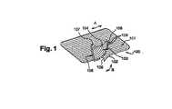
図1は、本発明に係るプロテーゼ100を斜視図で示している。このプロテーゼは、第1の編物片101を有しており、この編物片101は、第1の鎖編部(pillar stitch weave)を形成しており且つ矢印Aによって示された第1の方向に延びている第1のグループの糸102を、有している。このプロテーゼ100は、第2の編物片103を有しており、この編物片103は、第2の鎖編部を形成しており且つ矢印Bによって示された第2の方向に延びている第2のグループの糸104を、有している。例えば、前記グループの糸102、104は、鎖編部を形成している。編物の分野で一般的な編み方である鎖編と、これらを行うための方法とは、本分野の当業者によく知られている。従って、これらは以下に詳しく説明されない。本発明に係るプロテーゼ100を形成している糸と、特に、第1及び第2のグループの糸102、104とは、いかなる生物学的適合性の材料によっても形成され得る。本発明の例示的な一実施形態では、前記プロテーゼ100を形成している糸の少なくともいくつかは、ホットメルト材料によって形成されている。このプロテーゼの糸のために使用され得るホットメルト材料の例は、ポリプロピレン、ポリエステル、ポリ乳酸、また、これらの組み合わせである。 FIG. 1 shows a
前記第1及び第2の編物片101、103は、これらが部分的に重ね合わせられている接合部105で、互いに接合されている。これら第1及び第2の編物片101、103は、これらが前記接合部105以外の領域で部分的に重ね合わせられるように、組み合わされている。前記プロテーゼ100は、例えば、鼠径ヘルニアの治療に適した形状であり、この理由のために、プロテーゼ100がインプラントされる場合、精索の通路のためのスロット106とオリフィス107とを有している。前記第2の編物片103の、前記第1の編物片101に接するように意図されている面108には、突出したピコットブリストル109が設けられており、これらピコットブリストル109は、第2の編物片103に外側のプラッシュループステッチを形成してこれらプラッシュループの糸を部分的に融解することによって、得られる。このようなピコットブリストルを得る1つの方法が、例えばWO01/81667Aに開示されている。このようなピコットブリストル109は、前記ステッチで、また前記第1の編物片101の編物の糸間に係合し、かくして、前記第2の編物片103を第1の編物片101にロックするように、意図されている。 The first and second
図2は、図1に示されているプロテーゼ100の接合部105の概略図である。前記第1及び第2の編物片101、103は、前記接合部105に設けられている複数の互いに平行な溶接部110によって、一緒に組み合わされている。前記第1及び第2の編物片101、103は、前記第1の方向Aと第2の方向Bとが前記接合部105でほぼアラインメントされるように、組み合わされている。前記第1の鎖編部の鎖編は、前記第2の鎖編部の鎖編と重ね合わされている。前記溶接部は、細長い形状であり、これらの長軸は、前記第1及び第2の方向A、Bにアラインメントされており、またこれらは、前記接合部105の可撓性を維持するために、前記接合部全体に渡って、例えば均一な間隔によって互いに離間されている。前記溶接部の配置は、前記第1の鎖編部の少なくとも1つの鎖編と前記第2の鎖編部の少なくとも1つの鎖編とが前記接合部で一緒に溶接されるように、設定されている。好ましくは、前記第1及び第2の編物片101、103の鎖編は、全てが前記接合部で一緒に溶接されているのではなく、従って、各編物片101、103の少なくとも1つの鎖編、いくつかの実施形態では複数の鎖編、例えば前記全鎖編の10%から50%は、前記溶接部110の1つに含まれない。このことは、前記接合部105での可撓性を維持することを可能にする。かくして本出願人は、このプロテーゼ100の引裂強度が、溶接部110の代わりに編まれた縫い目が使用されているプロテーゼと比べて、より再現可能であり再生産可能であると、判断している。
FIG. 2 is a schematic view of the joint 105 of the
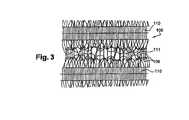
前記接合部105の拡大された概略図である図3は、前記接合部105に形成された前記溶接部110の離間によって保護されている複数のピコットブリストル109を示している。これらピコットブリストル109が存在することによって、前記接合部105でも、編物片103のグリップの性質を保持する効果がある。また、図3は、このプロテーゼ100が、複数の開口部111を有していることによって前記接合部105の溶接されていない糸間の孔、即ち隙間を維持する。このような多孔性は、前記接合部105でさえも細胞の定着を可能にするプロテーゼの性能を維持する。 FIG. 3, which is an enlarged schematic view of the joint 105, shows a plurality of picot bristles 109 that are protected by the separation of the
図4は、本発明の製造方法に適したソノトロード200の部分図である。このソノトロード200は、例えばチタンによって形成された本体201を有している。この本体は、これの一端部に、複数のレリーフ203を備えた、例えば矩形の接触面202を有している。図4が示すように、前記レリーフ203は、細長い形状、例えば矩形であり、互いに平行である。好ましくは、前記レリーフ203の長軸の方向が、前記ソノトロード200の前記接触面202の長軸の方向に直交するように選択されている。前記ソノトロード200は、互いに均一に離間されている複数のレリーフ203を有している。前記ソノトロードを使用して形成される溶接部110は、前記編物と前記レリーフ203との間での接触によって形成されるものである。この結果、前記複数の溶接部110は、前記レリーフ203とほぼ同じ形状と同じ間隔とを有している。 FIG. 4 is a partial view of a
図5は、接触面202の正面図であり、本発明の例示的な実施形態のために、前記接触面202及び前記レリーフ203のディメンションを示している。かくして、前記ソノトロード200は、幅aを有し間隔bによって均一に離間されている複数のレリーフ203を備えた、幅c、全長dを有する矩形の接触面202を有している。例えば、パラメータaは1mm、パラメータbは2.5mm、パラメータcは8mm、パラメータdは36mmの値をそれぞれ有している。パラメータaの値は、1つの同じ編物片の近接した2つの鎖編が同じ前記溶接部110に含まれるのを防ぐように、選択されている。 FIG. 5 is a front view of the
図6は、本発明に係る方法が、台300と一緒に本発明に係るソノトロード200を使用して実施される様子を示している。この台300は、例えばアルミニウムによって形成されており、プロテーゼ100を製造するために編物101、103の2つの片を組み合わせるために設けられる。第1の編物片101と第2の編物片103とは、接合部105で互いに重ねて配置されており、これらの片のそれぞれのグループの糸のそれぞれの方向A、Bが互いにほぼアラインメントされるように、前記台300の上に配置されている。前記ソノトロードの接触面202は、前記接合部105に対して垂直にアラインメントされて、この接合部105に接触される。前記編物片101、103と前記接触面との相対的な配置は、前記レリーフ203が、形成される前記溶接部110の選択された位置に垂直にアラインメントされるように、選択される。かくして、前記ソノトロード200が前記接合部105に接触されると、前記レリーフ203は、前記溶接部110の所望の位置に合わせられる。好ましくは、長さa、b、c、dと前記配置とは、前記レリーフ203が、従って前記溶接部110が、前記編物片101、103の少なくとも1つの鎖編に一致するように、選択される。このような部材の相対的な配置を容易にするために、前記台300は、例えば、予め規定された窪んだ形状もしくは隆起した形状を有しており、この結果、前記編物片101、103は、前記レリーフ203に対して精度良く配置される。 FIG. 6 shows how the method according to the invention is carried out using a
本発明に係る方法を実施するために、前記第1及び第2の編物部分(101、103)は、前述のように前記台300の上に配置され、そして前記ソノトロード200の前記接触面202は、前記接合部105に一致される。そして、圧力が、前記ソノトロードと前記台300との間に与えられる。そして、所定の超音波周波数で与えられる機械の振動が、前記ソノトロード200に与えられる。関連するエネルギーが、前記編物片(101,103)の繊維の局地的な融解によって複数の溶接部110を形成することを、可能にする。本発明に係る方法を適用するために、組み合わされる前記編物片に含まれる糸の少なくともいくつかは、ホットメルトの糸であることが、好ましい。前記編物片の糸のために使用され得るホットメルト材料の例は、ポリプロピレン、ポリエステル、ポリ乳酸、これらの混合物である。 In order to carry out the method according to the invention, the first and second knitted parts (101, 103) are arranged on the
最後に、前記ソノトロード200は、持ち上げられ、この結果、溶接部110によって組み合わせられている編物片(101、103)を有するプロテーゼ100は、元の状態に戻される。 Finally, the
このようにして、多孔性を示すプロテーゼが、形成される。言い換えると、このプロテーゼは、開口部111即ち隙間と、外科的使用に適した可撓性とを有し、更にこのプロテーゼは、機械的特性の観点、特に引裂強度の観点で良好な再生可能性を確実にする方法によって製造され、また、編まれた縫い目によって組み合わされている同様のプロテーゼを製造する方法と比較して、製造時間を減縮する。 In this way, a prosthesis exhibiting porosity is formed. In other words, the prosthesis has an
Claims (9)
Translated fromJapanese前記第1の方向Aと前記第2の方向Bとは、前記接合部(105)で互いにほぼアラインメントされており、前記接合部の前記溶接部(110)の各々は、前記第1及び第2の方向A、Bとアラインメントされた長軸を有する細長い形状を有している、プロテーゼ(100)において、
前記第1及び第2のグループの糸(102、104)は、少なくとも1つの第1の鎖編部と少なくとも1つの第2の鎖編部とを形成しており、前記第1及び第2の鎖編部の鎖編は、前記接合部で互いに重なり合っていることを特徴とするプロテーゼ(100)。A prosthesis (100) comprising at least one first knitted piece (101) and at least one second knitted piece (103), the first and second knitted pieces (101, 103) being Are welded together by a plurality of welds (110) positioned at the joint (105), wherein at least a part of the first knitted piece (101) and the second knitted fabric are joined at the joint. At least a part of the piece (103) is overlapped with each other, and the first knitted piece (101) isformed by a first group of yarns (102) extending in the first direction A.cage, the second knit piece (103)is formed by a thread (104) of the second group extending in a second directionB,
The first direction A and the second direction B are substantially aligned with each other at the joint (105), and each of the welds (110) of the joint includes the first and second directions. direction a,that has an elongated shape having a long axis that is B andalignment, the prosthesis (100),
The first and second groups of yarns (102, 104) form at least one first chain knitting portion and at least one second chain knitting portion, the first and second chain knitting portions. The prosthesis (100), wherein the chain stitches of the chain stitch part overlap each other at the joint part .
a)前記第1の編物片(101)の少なくとも一部分と前記第2の編物片(103)の少なくとも一部分とが接合部(105)で互いに重なり合うように、これら第1及び第2の編物片(101、103)を前記台(300)に配置することと、
b)前記第1及び第2の編物片(101、103)を前記台(300)と前記ソノトロード(200)との間でクランプするように、前記ソノトロード(200)の接触面(202)を前記接合部(105)に押圧することと、
c)前記接合部(105)に圧力を同時に与えることと、前記ソノトロード(200)に所定の超音波周波数で振動を与えることとを含む、方法。A method of manufacturing a prosthesis (100) according to anyone of claims1 to 8 , using a sonotrode (200) and a pedestal (300), wherein the sonotrode (200) In combination with at least two knitted pieces (101, 103), so that the sonotrode (200) presses the knitted pieces (101, 103) during welding. The contact surface (202) has an intended contact surface (202) that has aprosthesis (100), each having a plurality of reliefs (203) that are elongated and parallel to each other.Oite to a method of manufacturing,
a) These first and second knitted pieces (at least a part of the first knitted piece (101) and at least a part of the second knitted piece (103) overlap each other at the joint (105). 101, 103) on the platform (300);
b) contacting the contact surface (202) of the sonotrode (200) with the first and second knitted pieces (101, 103) between the platform (300) and the sonotrode (200); Pressing against the joint (105);
c) applying pressure to the joint (105) simultaneously and applying vibration to the sonotrode (200) at a predetermined ultrasonic frequency.
Applications Claiming Priority (3)
| Application Number | Priority Date | Filing Date | Title |
|---|---|---|---|
| FR08/04997 | 2008-09-11 | ||
| FR0804997AFR2935605B1 (en) | 2008-09-11 | 2008-09-11 | PROSTHETIC COMPRISING AN ASSEMBLY OF KNITTS, SONOTRODE AND METHOD OF MANUFACTURING BY SONIC SOLDER |
| PCT/IB2009/007031WO2010029438A1 (en) | 2008-09-11 | 2009-09-10 | Prosthesis comprising knitted material layers and method of manufacture by ultrasonic welding |
Publications (2)
| Publication Number | Publication Date |
|---|---|
| JP2012501778A JP2012501778A (en) | 2012-01-26 |
| JP5646487B2true JP5646487B2 (en) | 2014-12-24 |
Family
ID=40548626
Family Applications (1)
| Application Number | Title | Priority Date | Filing Date |
|---|---|---|---|
| JP2011526593AExpired - Fee RelatedJP5646487B2 (en) | 2008-09-11 | 2009-09-10 | Prosthesis comprising a knitted assembly and method for producing a prosthesis by sonic welding |
Country Status (7)
| Country | Link |
|---|---|
| US (1) | US8968419B2 (en) |
| EP (1) | EP2349074B1 (en) |
| JP (1) | JP5646487B2 (en) |
| AU (1) | AU2009290547B2 (en) |
| CA (1) | CA2735124A1 (en) |
| FR (1) | FR2935605B1 (en) |
| WO (1) | WO2010029438A1 (en) |
Families Citing this family (12)
| Publication number | Priority date | Publication date | Assignee | Title |
|---|---|---|---|---|
| AU2011232414A1 (en)* | 2010-03-24 | 2012-11-15 | Covidien Lp | Combination three-dimensional surgical implant |
| DE102011007844A1 (en)* | 2011-04-21 | 2012-10-25 | Aesculap Ag | Medical product and process for its preparation |
| FR2985270B1 (en) | 2011-12-29 | 2014-10-31 | Sofradim Production | KNIT WITH BANDS WITHOUT PICOTS |
| FR2985169B1 (en)* | 2011-12-29 | 2014-12-05 | Sofradim Production | KNIT WITH ZONES WITHOUT PICOTS |
| EP3269335B1 (en)* | 2012-10-02 | 2019-03-06 | McCullen, Seth | Implantable devices for musculoskeletal repair and regeneration |
| DE102012111734A1 (en)* | 2012-12-03 | 2014-06-05 | Schunk Sonosystems Gmbh | Ultrasonic welding device and method for welding electrical conductors |
| EP3613386A1 (en) | 2014-10-02 | 2020-02-26 | McCullen, Seth | Anatomically designed meniscus implantable devices |
| SG11201803220UA (en) | 2015-11-04 | 2018-05-30 | Poly Med Inc | Time dependent physiologic tissue scaffold |
| WO2018204440A2 (en) | 2017-05-02 | 2018-11-08 | Mccullen Seth | Composite joint implant |
| CN109875722B (en)* | 2019-02-03 | 2024-08-16 | 北京纺织科学研究所有限公司 | Composite hernia repair patch and manufacturing method thereof |
| US10981245B2 (en)* | 2019-09-24 | 2021-04-20 | GM Global Technology Operations LLC | Apparatus for ultrasonic welding of polymers and polymeric composites |
| JP7595559B2 (en)* | 2021-12-21 | 2024-12-06 | 三菱電機株式会社 | Semiconductor manufacturing apparatus and method for manufacturing semiconductor device |
Family Cites Families (17)
| Publication number | Priority date | Publication date | Assignee | Title |
|---|---|---|---|---|
| US5456711A (en)* | 1992-05-15 | 1995-10-10 | Intervascular Inc. | Warp knitted carotid patch having finished selvedged edges |
| US6113623A (en)* | 1994-04-20 | 2000-09-05 | Cabinet Beau De Lomenie | Prosthetic device and method for eventration repair |
| US5464488A (en)* | 1994-12-22 | 1995-11-07 | Albany International Corp. | Method of seaming plastic fabrics |
| US6120539A (en)* | 1997-05-01 | 2000-09-19 | C. R. Bard Inc. | Prosthetic repair fabric |
| FR2766698B1 (en)* | 1997-08-01 | 1999-11-05 | Cogent Sarl | ADJUSTED THREE-DIMENSIONAL PROSTHETIC FABRIC |
| US6287316B1 (en)* | 1999-03-26 | 2001-09-11 | Ethicon, Inc. | Knitted surgical mesh |
| FR2807936B1 (en)* | 2000-04-20 | 2002-08-02 | Sofradim Production | ABDOMINAL WALL REINFORCEMENT FOR THE TREATMENT OF INGUINAL HERNIA BY ANTERIOR VOLTAGE-FREE |
| FR2807937B1 (en)* | 2000-04-20 | 2002-08-02 | Sofradim Production | GRIPPED PROSTHETIC KNIT, MANUFACTURING METHOD THEREOF AND REINFORCEMENT IMPLANT FOR THE TREATMENT OF WALL DEFICITS |
| DE10019604C2 (en)* | 2000-04-20 | 2002-06-27 | Ethicon Gmbh | implant |
| FI113674B (en)* | 2002-12-18 | 2004-05-31 | Tamfelt Oyj Abp | Press felt |
| FR2853829B1 (en)* | 2003-04-16 | 2005-07-08 | Cie Euro Etude Rech Paroscopie | INTRODUCTION KIT FOR AN INTRA-GASTRIC IMPLANT, CASE FOR INTRODUCING SUCH AN IMPLANT AND CORRESPONDING MANUFACTURING METHOD |
| US20050070930A1 (en)* | 2003-09-30 | 2005-03-31 | Gene W. Kammerer | Implantable surgical mesh |
| AU2006210494B2 (en)* | 2005-02-04 | 2011-01-06 | Ams Research Corporation | Needle design for male transobturator sling |
| US20070055093A1 (en)* | 2005-09-08 | 2007-03-08 | Jean-Marc Beraud | Implantable warp knitted fabric |
| JP2009533136A (en)* | 2006-04-13 | 2009-09-17 | ケーシーアイ ライセンシング インコーポレイテッド | Medical occlusion screen mounting system and method |
| US7614258B2 (en)* | 2006-10-19 | 2009-11-10 | C.R. Bard, Inc. | Prosthetic repair fabric |
| ITMI20081186A1 (en)* | 2008-06-27 | 2009-12-28 | Herniamesh S R L | LIGHTWEIGHT SURGICAL MESH. |
- 2008
- 2008-09-11FRFR0804997Apatent/FR2935605B1/ennot_activeExpired - Fee Related
- 2009
- 2009-09-10EPEP09740744.9Apatent/EP2349074B1/enactiveActive
- 2009-09-10AUAU2009290547Apatent/AU2009290547B2/ennot_activeCeased
- 2009-09-10WOPCT/IB2009/007031patent/WO2010029438A1/enactiveApplication Filing
- 2009-09-10CACA2735124Apatent/CA2735124A1/ennot_activeAbandoned
- 2009-09-10USUS13/063,336patent/US8968419B2/enactiveActive
- 2009-09-10JPJP2011526593Apatent/JP5646487B2/ennot_activeExpired - Fee Related
Also Published As
| Publication number | Publication date |
|---|---|
| CA2735124A1 (en) | 2010-03-18 |
| FR2935605A1 (en) | 2010-03-12 |
| JP2012501778A (en) | 2012-01-26 |
| US20110166494A1 (en) | 2011-07-07 |
| US8968419B2 (en) | 2015-03-03 |
| EP2349074B1 (en) | 2016-06-15 |
| AU2009290547B2 (en) | 2015-02-05 |
| FR2935605B1 (en) | 2010-10-01 |
| WO2010029438A1 (en) | 2010-03-18 |
| EP2349074A1 (en) | 2011-08-03 |
| AU2009290547A1 (en) | 2010-03-18 |
Similar Documents
| Publication | Publication Date | Title |
|---|---|---|
| JP5646487B2 (en) | Prosthesis comprising a knitted assembly and method for producing a prosthesis by sonic welding | |
| JP6049218B2 (en) | Artery for umbilical hernia | |
| AU619445B2 (en) | Pad-like implant | |
| US8298290B2 (en) | Implantable prosthesis for soft tissue repair | |
| US9883933B2 (en) | Medical device and method of delivering the medical device | |
| RU2656549C2 (en) | Mesh assembly and manufacturing method thereof | |
| WO2005007208A1 (en) | Suture prosthetic material for automatic sewing device | |
| JP2005525166A (en) | Prosthetic repair fibers with erosion resistant edges | |
| JP2012504457A (en) | Implantable prosthesis | |
| BR112014023806B1 (en) | BIOCOMPATIBLE MESH IMPLANT | |
| CN113825454A (en) | Felt material for use in a method of repairing or strengthening soft tissue of a human or animal | |
| JP5339649B2 (en) | Soft tissue treatment instrument | |
| JP7377258B2 (en) | medical device | |
| JP3090439B2 (en) | Annular artificial ligament | |
| JP7386232B2 (en) | medical device | |
| JP4409161B2 (en) | Suture prosthesis for automatic suturing device | |
| JP2021520953A (en) | Coined suture threading drill | |
| JP3816603B2 (en) | Stent | |
| JP2021159095A (en) | Medical instrument and medical instrument set | |
| JP2020162781A (en) | Medical device | |
| CN105361975A (en) | Hernia patch and production method thereof |
Legal Events
| Date | Code | Title | Description |
|---|---|---|---|
| A621 | Written request for application examination | Free format text:JAPANESE INTERMEDIATE CODE: A621 Effective date:20120719 | |
| A131 | Notification of reasons for refusal | Free format text:JAPANESE INTERMEDIATE CODE: A131 Effective date:20131112 | |
| A601 | Written request for extension of time | Free format text:JAPANESE INTERMEDIATE CODE: A601 Effective date:20140207 | |
| A602 | Written permission of extension of time | Free format text:JAPANESE INTERMEDIATE CODE: A602 Effective date:20140217 | |
| A521 | Request for written amendment filed | Free format text:JAPANESE INTERMEDIATE CODE: A523 Effective date:20140422 | |
| TRDD | Decision of grant or rejection written | ||
| A01 | Written decision to grant a patent or to grant a registration (utility model) | Free format text:JAPANESE INTERMEDIATE CODE: A01 Effective date:20141007 | |
| A61 | First payment of annual fees (during grant procedure) | Free format text:JAPANESE INTERMEDIATE CODE: A61 Effective date:20141105 | |
| R150 | Certificate of patent or registration of utility model | Ref document number:5646487 Country of ref document:JP Free format text:JAPANESE INTERMEDIATE CODE: R150 | |
| LAPS | Cancellation because of no payment of annual fees |