JP5645200B2 - Lighting device - Google Patents
Lighting deviceDownload PDFInfo
- Publication number
- JP5645200B2 JP5645200B2JP2010100877AJP2010100877AJP5645200B2JP 5645200 B2JP5645200 B2JP 5645200B2JP 2010100877 AJP2010100877 AJP 2010100877AJP 2010100877 AJP2010100877 AJP 2010100877AJP 5645200 B2JP5645200 B2JP 5645200B2
- Authority
- JP
- Japan
- Prior art keywords
- dimming rate
- light
- button
- color
- cpu
- Prior art date
- Legal status (The legal status is an assumption and is not a legal conclusion. Google has not performed a legal analysis and makes no representation as to the accuracy of the status listed.)
- Active
Links
Images


Landscapes
- Circuit Arrangement For Electric Light Sources In General (AREA)
- Led Devices (AREA)
Description
Translated fromJapaneseこの発明は、照明装置に関し、特に発光ダイオード(LED(Light Emitting Diode))を光源とする照明装置に関する。 The present invention relates to a lighting device, and more particularly to a lighting device using a light emitting diode (LED) as a light source.
従来の照明装置は、白熱電球や蛍光灯を使用したものが一般的であり、点灯、消灯、出力調整による調光、常夜灯(豆球)の点灯などがあった。 Conventional lighting devices generally use incandescent bulbs or fluorescent lamps, such as turning on / off, dimming by adjusting output, turning on a night light (bean bulb), and the like.
近年、発光ダイオード(LED)の進化がめざましく、高輝度・高出力でさまざまな波長出力を持つLEDが実用化されてきている。このようなLEDを用いた照明装置においては、点灯や消灯などの操作だけでなく、波長の違うLEDを組み合わせて各々の出力を調整することにより、使用者は照明の色調も自由に変更することが可能である。 In recent years, the evolution of light emitting diodes (LEDs) has been remarkable, and LEDs having various luminance outputs with high luminance and high output have been put into practical use. In such an illuminating device using LEDs, the user can freely change the color tone of the illumination by adjusting each output by combining LEDs with different wavelengths in addition to operations such as turning on and off. Is possible.
特開2008−305759号公報においては、LEDの出力の調整に関して、LEDを駆動するPWM信号のデューティ比を調整する方式が開示されている。 Japanese Patent Laid-Open No. 2008-305759 discloses a method for adjusting the duty ratio of a PWM signal for driving an LED with respect to adjustment of the output of the LED.
しかしながら、一般的にLEDの出力を調整するにあたり、PWM信号のデューティ比とLEDの出力とは理想的な線形関係にあるとして、デューティ比の調整が行なわれているが、実際のLEDの出力特性線は、理想とは異なる場合がある。 However, in general, when adjusting the output of the LED, the duty ratio is adjusted on the assumption that the duty ratio of the PWM signal and the output of the LED are in an ideal linear relationship. The line may be different from the ideal.
したがって、LEDから所望の出力となるようにデューティ比を調整した場合であっても実際の出力とは異なるため精度の高い調光を実行することができないという問題がある。 Therefore, even when the duty ratio is adjusted so as to obtain a desired output from the LED, there is a problem that high-precision light control cannot be performed because it differs from the actual output.
本発明は、上記のような問題を解決するためになされたものであって、精度の高い調光が可能な照明装置を提供することを目的とする。 The present invention has been made to solve the above-described problems, and an object of the present invention is to provide an illumination device capable of highly precise light control.
本発明のある局面に従う照明装置は、発光部と、発光部を点灯させる点灯期間と、前記発光部を消灯させる消灯期間とを有する周期的な周期期間に関する点消灯制御を実行する制御回路とを備える。制御回路は、予め測定された前記発光部に対する前記点灯期間に応じた調光率の特性データに基づいて、所望の調光率に従う点灯期間に設定する。 An illuminating device according to an aspect of the present invention includes a light emitting unit, a lighting circuit that turns on the light emitting unit, and a control circuit that performs a lighting control for a periodic cycle period that includes a lighting period that turns off the light emitting unit. Prepare. The control circuit sets the lighting period according to the desired dimming rate based on the characteristic data of the dimming rate according to the lighting period for the light emitting unit measured in advance.
好ましくは、制御回路は、前記特性データの近似式に基づいて、前記所望の調光率に従う点灯期間に設定する。 Preferably, the control circuit sets the lighting period according to the desired dimming rate based on the approximate expression of the characteristic data.
特に、特性データは、調光率の範囲により規定される複数の領域に分割される。各々の領域における前記特性データの近似式が算出される。制御回路は、前記所望の調光率が属する範囲に対応する算出された近似式に基づいて、前記所望の調光率に従う点灯期間に設定する。 In particular, the characteristic data is divided into a plurality of areas defined by the range of dimming rate. An approximate expression of the characteristic data in each region is calculated. The control circuit sets the lighting period according to the desired dimming rate based on the calculated approximate expression corresponding to the range to which the desired dimming rate belongs.
上記の構成によれば、照明装置における制御回路は、予め測定された発光部に対する点灯期間に応じた調光率の特性データに基づいて、所望の調光率に従う点灯期間に設定する。したがって、実際に測定した特性データに基づいてデューティ比である点灯期間が設定されるため制度の高い調光が可能となる。 According to said structure, the control circuit in an illuminating device sets to the lighting period according to a desired light control rate based on the characteristic data of the light control rate according to the lighting period with respect to the light emission part measured beforehand. Therefore, since the lighting period, which is the duty ratio, is set based on the actually measured characteristic data, it is possible to perform high-level light control.
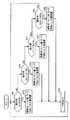
以下、本発明の実施の形態について、図面を参照して説明する。以下の説明では、同一の部品には同一の符号を附してある。それらの名称および機能も同じである。したがって、それらについての詳細な説明は繰返さない。 Embodiments of the present invention will be described below with reference to the drawings. In the following description, the same parts are denoted by the same reference numerals. Their names and functions are also the same. Therefore, detailed description thereof will not be repeated.
図1は、本発明の実施の形態に従う照明装置1の外観構成図である。
図1を参照して、本発明の実施の形態に従う照明装置1には、本体部を取り付けるためのシャーシ2と、シャーシ2とともに本体部全面を覆うカバー8,9とが設けられている場合が示されている。本例においては、一例として、照明装置1のシャーシ2が天井に取り付けられているものとする。FIG. 1 is an external configuration diagram of
Referring to FIG. 1,
カバー8は、照明用のLEDモジュールが配置される領域に対応して設けられる。当該カバー8の領域から光が照射される。 The cover 8 is provided corresponding to a region where the LED module for illumination is arranged. Light is irradiated from the region of the cover 8.
カバー8の中央付近に設けられている別のカバー9は、LEDモジュールを制御する基板等の制御装置が配置される領域に対応して設けられる。当該カバー9に対応する領域には、LEDモジュールは設けられていないため光は照射されない。 Another
また、当該照明装置1を操作するための携帯型のリモコン50が設けられている。リモコン50を操作することにより照明装置1に対して各種動作指示を与えることが可能となる。リモコン50の詳細については後述する。 In addition, a portable
図2は、本発明の実施の形態に従う照明装置1のハードウェアを説明する概略ブロック図である。 FIG. 2 is a schematic block diagram illustrating hardware of
図2を参照して、本発明の実施の形態に従う照明装置1は、電源回路10と、照明制御部20と、照明部30と、インタフェース部40とを含む。 Referring to FIG. 2,
電源回路10は、交流電源入力(AC入力)(100V)を受けて直流電圧に変換して装置の各部に電圧を供給する。なお、本例においては、一例として制御電源供給回路21および照明部30のみに電圧が供給されているように示されているが、特にこれに限られず、他の部位に対しても必要な電圧が供給されるものとする。 The
照明制御部20は、電源回路10から供給される電圧をCPU22に供給するために調整する制御電源供給回路21と、照明装置1全体を制御するためのCPU(Central Processing Unit)22と、PWM(Pulse Width Modulation)制御回路23と、信号受信部25と、SW入力部26と、照度センサ28と、メモリ29とを含む。CPU22とメモリ29とPWM制御回路23とはマイコン(マイクロコンピュータ)によって構成される。 The
CPU22は、各部と接続されるとともに、照明装置1全体を制御するために必要な動作を指示する。 CPU22 is connected with each part and instruct | indicates operation | movement required in order to control the
PWM制御回路23は、CPU22からの指示に従ってLEDモジュール31,32を駆動するために必要なPWMパルスを生成する。 The
信号受信部25は、インタフェース部40に含まれる赤外線受光部41と接続されて、赤外線受光部41で受光された赤外線信号に応答した指示をCPU22に出力する。 The
SW入力部26は、操作SW(スイッチ)42と接続されて、操作SWの操作に応答した指示をCPU22に出力する。 The
照度センサ28は、照明装置1周辺の照度を計測してCPU22に出力する。CPU22は、照度センサ28からの測定結果に基づいて調光率を制御することが可能である。 The
メモリ29は、照明装置1を制御するための各種プログラムおよび初期値等が格納されるとともに、CPU22のワーキングメモリとしても用いられる。 The
照明部30は、互いに色温度の異なるLEDモジュール31,32と、LEDモジュール31,32を駆動するために用いられるFET(Field Effect Transistor)スイッチ33,34とを含む。本例において、LEDモジュール31の色温度は、6700K程度、LEDモジュール32の色温度は、2700K程度とする。以下、LEDモジュール31を昼光色LED(単に昼光色)とも称する。また、LEDモジュール32を電球色LED(単に電球色)とも称する。なお、ここでは、LEDモジュール31,32は、それぞれ1つずつ1組として設けられている場合が示されているが、複数組が設けられる構成とすることも可能である。また、FETスイッチ33,34はPWM制御回路23にあってもよい。 The
インタフェース部40は、赤外線受光部41と、操作SW42とを含む。
赤外線受光部41は、上述したリモコン50からの赤外線信号を受光する。そして、赤外線信号を光電変換して信号受信部25に出力する。The
The infrared light receiving unit 41 receives an infrared signal from the
操作SW42は、電源スイッチ等を含み、ユーザの電源スイッチ等のスイッチ操作に応答した指示がSW入力部26を介してCPU22に出力される。なお、電源スイッチがオンの場合には、照明装置1には必要な電源が供給され、電源スイッチがオフの場合には、照明装置1には電源が供給されないものとする。本例における各種動作については、電源スイッチがオンの場合とする。 The
図3は、本発明の実施の形態に従うLEDモジュール31,32の構成を説明する図である。 FIG. 3 is a diagram illustrating a configuration of
図3を参照して、CPU22は、PWM制御回路23に指示してLEDモジュール31,32の少なくとも一方を駆動するためのPWMパルスS1,S2を生成して出力する。 Referring to FIG. 3,
LEDモジュール31,32は、電源回路10から必要な電圧の供給を受ける。LEDモジュール31,32と接地電圧GNDとの間には、FETスイッチ33,34とがそれぞれ設けられている。 The
そして、PWMパルスS1,S2に応答してFETスイッチ33,34が導通/非導通となることによりLEDモジュール31,32に電流が供給/遮断される。LEDモジュール31,32に電流が供給されることによりLEDモジュール31,32はそれぞれ発光する。なお、ここでは、LEDモジュール31,32を駆動する構成について説明したが、他のLEDモジュールがさらに複数個設けられている場合についても同様である。 Then, the FET switches 33 and 34 are turned on / off in response to the PWM pulses S1 and S2, whereby current is supplied / cut off to the
図4は、LEDモジュール31,32が照明装置1に配置されている場合の一例を説明する図である。 FIG. 4 is a diagram for explaining an example when the
図4を参照して、LEDモジュール31,32を互いに隣接して配置し、かつ、複数組円形状に配列して実装した場合が示されている。色温度の異なるLEDモジュール31,32を互いに隣接して実装することにより、それぞれのLEDモジュールから発光される光を混ざりやすくし、照射面での色のバラツキ、ムラを無くすことが可能となる。 Referring to FIG. 4, a case where
図5は、本発明の実施の形態に従うリモコン50の外観構成図である。
図5を参照して、リモコン50は、液晶パネル52と、各種ボタンが設けられている。液晶パネル52は、液晶以外の他の表示装置を用いることも可能である。FIG. 5 is an external configuration diagram of
Referring to FIG. 5,
また、ここでは、複数のボタンが設けられている。具体的には、「点灯」ボタン54と、「昼光色/電球色」切り替えボタン56と、「照度センサ」ボタン70と、数値等の上げ下げを指示するための「+/−」ボタン74とが設けられる。 Here, a plurality of buttons are provided. Specifically, a “lighting”
また、ここでは、複数のボタンが設けられている。具体的には、「全灯」ボタン54と、「消灯」ボタン53と、調光率の上げ下げを指示するための「アップ」ボタン57Aおよび「ダウン」ボタン57Bと、「電球色」ボタン59Aおよび「昼光色」ボタン59Bと、「照度センサ」ボタン70と、数値等の上げ下げを指示するための「+/−」ボタン74とが設けられる。 Here, a plurality of buttons are provided. Specifically, an “all light”
ユーザが「全灯」ボタン54を押下することにより全点灯制御指示がリモコン50から出力される。照明装置1のCPU22は、リモコン50からの全点灯制御指示の入力を受けて、PWM制御回路23に対して照明部30への全点灯制御を開始するように指示する。これにより、「全灯」ボタン54の押下すなわち、リモコン50からの全点灯制御指示の入力に従って、照明部30から調光率100%の光が照射される。 When the user presses the “all lights”
照明部30から照射される光の調光率は、「アップ」ボタン57Aおよび「ダウン」ボタン57Bの操作によって段階的に全灯(調光率100%)から微灯(調光率30%)まで調整される。具体的には、例えば、「全灯」ボタン54が押下されて全灯(調光率100%)である状態で「ダウン」ボタン57Bが押下されたときには半灯(調光率50%)となり、その状態で「ダウン」ボタン57Bが押下されたときには微灯(調光率30%)となる。また、その状態で「アップ」ボタン57Aが押下されたときには半灯(調光率50%)となり、その状態で「アップ」ボタン57Aが押下されたときには全灯(調光率100%)となる。なお、現在の調光率はメモリ29に記憶されているものとする。 The dimming rate of the light emitted from the illuminating
点灯中にユーザが「消灯」ボタン53を押下することにより消灯制御指示がリモコン50から出力される。照明装置1のCPU22は、リモコン50からの消灯制御指示の入力を受けて、PWM制御回路23に対して照明部30を消灯するように指示する。これにより、「消灯」ボタン53の押下すなわち、リモコン50からの消灯制御指示の入力に従って、照明部30からの光の照射が終了する。 When the user presses the “light-off”
また、ユーザが「電球色」ボタン59Aおよび「昼光色」ボタン59Bを押下することにより色調の切り替え指示がリモコン50から出力される。照明装置1のCPU22は、リモコン50からの色調の切り替え指示の入力を受けてPWM制御回路23に対して照明部30への点灯切り替えを指示する。ここで、「電球色」ボタン59Aおよび「昼光色」ボタン59Bの押下すなわち、リモコン50からの色調の切り替え指示の入力に従って、照明部30から照射する光の色調を調整可能であるものとする。具体的には、「電球色」ボタン59Aが押下された場合には、調光率は維持しつつ昼光色から電球色に段階的に切り替わるように設定されるものとする。例えば、昼光色の全灯(調光率100%)である「昼光色」の状態で「電球色」ボタン59Aが押下されたときには、昼光色を調光率70%、電球色を調光率30%の「半昼光色」に設定して、調光率は維持しつつ色味を昼光色から電球色側に変化させる。その状態でさらに「電球色」ボタン59Aが押下されたときには、昼光色を調光率30%、電球色を調光率70%の「半電球色」に設定して、調光率は維持しつつ色味をさらに昼光色から電球色側に変化させる。また、「昼光色」ボタン59Bが押下された場合には、調光率は維持しつつ電球色から昼光色に段階的に切り替わるように設定されるものとする。例えば、電球色の全灯(調光率100%)である「電球色」の状態で「昼光色」ボタン59Bが押下されたときには、電球色を調光率70%、昼光色を調光率30%の「半電球色」に設定して、調光率は維持しつつ色味を電球色から昼光色側に変化させる。その状態でさらに「昼光色」ボタン59Bが押下されたときには、電球色を調光率30%、昼光色を調光率70%の「半昼光色」に設定して、調光率は維持しつつ色味をさらに電球色から昼光色側に変化させる。なお、現在の色調はメモリ29に記憶されているものとする。 Further, when the user presses the “bulb color”
当該操作に従って、ユーザが「アップ」ボタン57Aおよび「ダウン」ボタン57Bあるいは「電球色」ボタン59Aおよび「昼光色」ボタン59Bを操作することによりユーザの好みの調光率および色調に変化させて快適な光環境を実現することが可能である。 According to the operation, the user operates the “up”
また、ユーザが「照度センサ」ボタン70を押下することにより、照度センサの動作指示がリモコン50から出力される。照明装置1のCPU22は、リモコン50からの照度センサ28の動作指示の入力を受けて、照度センサ28において計測された測定結果を取得する。そして、CPU22は、照度センサ28から取得した測定結果に基づいて調光率を制御する。例えば、照度センサ28の測定結果に基づいて、太陽光(自然光)の入光により部屋等の室内環境が十分に明るいと判断される場合には、設定されている調光率を下げて照度を調整することが可能である。これにより消費電力を低減することが可能である。また、逆に太陽光(自然光)が遮断されて部屋等の室内環境が暗いと判断される場合には、設定されている調光率を限度として、再び調光率を上げることにより適切な照度となるように調整することが可能である。また、ユーザが「照度センサ」ボタン70を再度押下することにより、照度センサの動作停止指示がリモコン50から出力される。照明装置1のCPU22は、リモコン50からの照度センサ28の動作停止指示の入力を受けて、照度センサ28において計測された測定結果に基づく調光率の制御を停止する。これにより照度センサ28での測定結果に係わらずユーザの望む調光率に設定することが可能となる。 Further, when the user presses the “illuminance sensor”
図6は、本発明の実施の形態に従うリモコン50のハードウェアを説明する概略ブロック図である。 FIG. 6 is a schematic block diagram illustrating hardware of
図6を参照して、本発明の実施の形態に従うリモコン50は、電源回路51と、リモコン制御部55と、インタフェース部56とを含む。 Referring to FIG. 6,
電源回路51は、2次電池等のバッテリからの電力の供給を受けて装置の各部に電圧を供給する。なお、本例においては、一例として制御電源供給回路81にのみ電圧が供給されているように示されているが、特にこれに限られず、他の部位に対しても必要な電圧が供給されるものとする。 The
リモコン制御部55は、電源回路51から供給される電圧をCPU86に供給するために調整する制御電源供給回路81と、リモコン50全体を制御するためのCPU(Central Processing Unit)86と、液晶パネル52を駆動する液晶駆動回路82と、信号送信部84と、SW入力部83と、メモリ80とを含む。 The remote controller controller 55 controls a control
CPU86は、各部と接続されるとともに、リモコン50全体を制御するために必要な動作を指示する。 The
液晶駆動回路82は、CPU86からの指示に従って所望の画面を表示する液晶パネル52を駆動する。 The liquid
信号送信部84は、CPU86からの指示をインタフェース部56に含まれる赤外線投光部87に出力する。 The
SW入力部83は、操作SW(スイッチ)88と接続されて、操作SWの操作に応答した指示をCPU86に出力する。 The
メモリ80は、リモコン50を制御するためのプログラムおよび初期値等が格納されるとともに、CPU86のワーキングメモリとしても用いられる。 The
インタフェース部56は、赤外線投光部87と、操作SW88と、液晶パネル52とを含む。 The
赤外線投光部87は、信号送信部84から出力された信号を赤外線信号に変換して照明装置1に投光する。 The infrared
操作SW88は、上述したリモコン50に設けられた各種のボタンで構成されている。具体的には、「全灯」ボタン54と、「消灯」ボタン53と、調光率の上げ下げを指示するための「アップ」ボタン57Aおよび「ダウン」ボタン57Bと、「電球色」ボタン59Aおよび「昼光色」ボタン59Bと、「照度センサ」ボタン70と、数値等の上げ下げを指示するための「+/−」ボタン74とが設けられる。 The
リモコン50のCPU86は、SW入力部83を介して操作SW88における各ボタンの入力指示を受けて、信号送信部84に各ボタンに応じた送信信号の出力を指示する。信号送信部84は、CPU86からの指示に応答して、赤外線投光部87を介して各ボタンに応じた送信信号を赤外線信号として照明装置1に出力する。照明装置1の赤外線受光部41は、リモコン50の赤外線投光部87から投光された赤外線信号を受信する。そして、赤外線受光部41は、受光された赤外線信号を光電変換する。そして、信号受信部25は、光電変換により得られたリモコン50から指示された送信信号をCPU22に出力する。当該動作により、CPU22は、リモコン50からの入力指示に応じた動作を実行する。 The
具体的には、上述したようにユーザが「アップ」ボタン57Aまたは「ダウン」ボタン57Bを押下することによりCPU22は、照明部30におけるLEDモジュール31,32の発光に従う調光率を調整する。 Specifically, as described above, when the user presses the “up”
例えば、全灯(調光率100%)である状態で「ダウン」ボタン57Bが押下されるに従って「全灯」→「半灯」→「微灯」と変化し、その状態(調光率30%)「アップ」ボタン57Aが押下されるに従って「微灯」→「半灯」→「全灯」と変化する。 For example, as the “down”
また、上述したようにユーザが「電球色」ボタン59Aまたは「昼光色」ボタン59Bを押下することによりCPU22は、照明部30におけるLEDモジュール31,32の発光に従う色調を調整する。例えば、昼光色の全灯(調光率100%)である「昼光色」の状態で「電球色」ボタン59Aが押下されるに従って「昼光色」→「半昼光色」→「半電球色」→「電球色」と変化し、その状態(電球色)で「昼光色」ボタン59Bが押下されるに従って「電球色」→「半電球色」→「半昼光色」→「昼光色」と変化する。 Further, as described above, when the user presses the “bulb color”
なお、本例においては、携帯型のリモコン50について説明したが、特にこれに限られず、壁面に設けられた固定式のリモコンとすることも可能である。また、当該リモコンを照明装置1のインタフェース部40の一部として設けるようにしても良い。その場合、赤外線信号により操作SWの信号を送信するのではなく、直接、信号線を用いて操作SWからの指示信号を送信する構成とすることも可能である。また、信号の送受信は、赤外線に限られず、無線等を用いるようにしても良い。 In the present example, the portable
次に、本発明の実施の形態に従うLEDモジュールの点消灯制御について説明する。
本発明の実施の形態に従うPWM制御回路23は、CPU22からの指示に従って、LEDモジュール31,32に出力するPWMパルスS1,S2を制御する。より、具体的には、PWMパルスS1のオン期間に従ってFETスイッチ33が導通してLEDモジュール31が点灯する。また、PWMパルスS1のオフ期間に従ってFETスイッチ33が非導通となっていLEDモジュール31が消灯する。Next, lighting on / off control of the LED module according to the embodiment of the present invention will be described.
The
LEDモジュール32についても同様に、PWM制御回路23からのPWMパルスS2に従ってFETスイッチ34が導通/非導通となって点灯および消灯する。 Similarly, the
CPU22は、図示しないが40MHz(1周期25ns)の発振信号を出力する水晶発振子と接続されており、当該発振信号に同期したタイミングによる指示に従ってPWM制御回路23は、PWMパルスS1,S2を出力する。 Although not shown, the
図7は、本発明の実施の形態に従うPWM制御回路23から出力されるPWMパルスの生成を説明する図である。 FIG. 7 is a diagram illustrating generation of a PWM pulse output from the
図7を参照して、PWM制御回路23から出力されるPWMパルスS1,S2は、当該発振信号の最小単位である1周期25nsを最小単位としてその周期個数分(ここではZ個)に従って設定される。ここでは、点灯期間Tonおよび消灯期間Toffについて設定される場合が示されている。 Referring to FIG. 7, PWM pulses S1 and S2 output from
調光率100%とする場合の点灯期間Tonは、LEDモジュール31,32等に供給される電流がLEDモジュール31,32等の定格電流を越えないようにある程度のマージンを設けて設定される。 The lighting period Ton when the dimming rate is 100% is set with a certain margin so that the current supplied to the
そして、点灯期間Tonおよび消灯期間Toffを合わせた周期期間Tは、調光率100%とする場合の点灯期間よりも幾分長く設定される。したがって、例えば、調光率100%となる点灯期間よりも幾分長く点灯期間Tonを設定することが可能となり、LEDモジュール31,32等に定格電流に近い値の電流を供給することにより100%以上の調光率に設定することも可能である。 Then, the cycle period T including the lighting period Ton and the extinguishing period Toff is set somewhat longer than the lighting period when the dimming rate is 100%. Therefore, for example, it is possible to set the lighting period Ton somewhat longer than the lighting period at which the dimming rate is 100%, and by supplying a current close to the rated current to the
一方、上述したように、周期期間Tにおける点灯期間Tonのデューティ比を調整して、LEDモジュール31,32の調光率を調整する場合、LEDモジュール31,32の出力特性のばらつきにより実際の調光率とは異なる場合がある。 On the other hand, as described above, when the duty ratio of the lighting period Ton in the period T is adjusted to adjust the dimming rate of the
図8は、本発明の実施の形態に従うPWMパルスの周期期間Tにおける点灯期間Tonのデューティ比を調整した場合におけるLEDモジュール31,32の調光率の変化を説明する図である。 FIG. 8 is a diagram illustrating a change in the dimming rate of the
図8を参照して、理想的には、PWMパルスの周期期間Tにおける点灯期間Tonのデューティ比を線形に変化させた場合に調光率は線形に変化することが望ましい。一般的には、PWMパルスのデューティ比は、PWMパルスのデューティ比を100%にした場合の調光率を100%とした線形の出力特性線(理想)に従って算出される。 Referring to FIG. 8, ideally, it is desirable that the dimming rate change linearly when the duty ratio of the lighting period Ton in the period T of the PWM pulse is changed linearly. In general, the duty ratio of the PWM pulse is calculated according to a linear output characteristic line (ideal) where the dimming rate is 100% when the duty ratio of the PWM pulse is 100%.
しかしながら、実際のLEDモジュール31,32の調光率の出力特性線は、図示されるように理想的な出力特性線とは異なる。 However, the output characteristic line of the dimming rate of the
したがって、調光率に応じたPWMパルスのデューティ比を算出するにあたり、理想的な出力特性線によりデューティ比を設定した場合には所望の調光率と異なる調光率に設定されている可能性がある。 Therefore, in calculating the duty ratio of the PWM pulse according to the dimming rate, when the duty ratio is set by an ideal output characteristic line, there is a possibility that the dimming rate is different from the desired dimming rate. There is.
図9は、本発明の実施の形態に従うLEDモジュール31(昼光色LED)に対して実際に計測した調光率とPWMパルス値との関係を説明する図である。 FIG. 9 is a diagram illustrating the relationship between the dimming rate actually measured for the LED module 31 (daylight color LED) according to the embodiment of the present invention and the PWM pulse value.
図9を参照して、ここでは、縦軸がPWMパルス値(周期個数)、横軸が調光率(%)とした場合の出力特性線が示されている。 Referring to FIG. 9, here, an output characteristic line in the case where the vertical axis is a PWM pulse value (number of cycles) and the horizontal axis is a dimming rate (%) is shown.
本例においては、一例としてPWMパルス値が1670の場合に点灯期間Tonのデューティ比が100%に設定されるものとする。 In this example, as an example, when the PWM pulse value is 1670, the duty ratio of the lighting period Ton is set to 100%.
図10は、本発明の実施の形態に従うLEDモジュール32(電球色LED)に対して実際に計測した調光率とPWMパルス値との関係を説明する図である。 FIG. 10 is a diagram illustrating the relationship between the dimming rate actually measured for the LED module 32 (bulb color LED) and the PWM pulse value according to the embodiment of the present invention.
図10を参照して、ここでは、縦軸がPWMパルス値(周期個数)、横軸が調光率(%)とした場合の出力特性線が示されている。 Referring to FIG. 10, here, the output characteristic line when the vertical axis is the PWM pulse value (number of cycles) and the horizontal axis is the dimming rate (%) is shown.
図11は、LEDモジュール31,32の出力特性線の近似式を説明する図である。
図11を参照して、図9のLEDモジュール31の出力特性線に従う昼光色LEDの近似式と、図10のLEDモジュール32の出力特性線に従う電球色LEDの近似式とが示されている。FIG. 11 is a diagram for explaining an approximate expression of the output characteristic lines of the
Referring to FIG. 11, there are shown an approximate expression of daylight color LED according to the output characteristic line of
ここでは、昼光色LEDの近似式に関して、図9で示される出力特性線に従う調光率を4つの領域に分割して、それぞれの領域における近似式を算出した場合が示されている。一例として、「調光率0〜60.0%」、「調光率60.1%〜91.0%」、「調光率91.1%〜98.0%」、「調光率98.1%〜100.0%」に分割した場合が示されている。そして、ここでは、さらに近似式をCPU22での処理を容易にするために演算式に変形した場合が示されている。CPU22は、当該演算式を用いて変数に所望の調光率を入力することにより実際のLEDモジュール31の出力特性線に従う所望のPWMパルス値を算出することが可能となる。 Here, regarding the approximate expression of daylight color LED, the case where the dimming rate according to the output characteristic line shown in FIG. 9 is divided into four areas and the approximate expression in each area is calculated is shown. As an example, “
同様に、昼光色LEDの近似式に関して、図10で示される出力特性線に従う調光率を4つの領域に分割して、それぞれの領域における近似式を算出した場合が示されている。一例として、「調光率0〜82.5%」、「調光率82.6%〜97.0%」、「調光率97.1%〜99.9%」、「調光率100%」に分割した場合が示されている。そして、ここでは、さらに近似式をCPU22での処理を容易にするために演算式に変形した場合が示されている。CPU22は、当該演算式を用いて変数に所望の調光率を入力することにより実際のLEDモジュール32の出力特性線に従う所望のPWMパルス値を算出することが可能となる。なお、図9,10においては、当該演算式を用いた近似特性線が太線で示されている。 Similarly, regarding the approximate expression of the daylight color LED, the case where the dimming rate according to the output characteristic line shown in FIG. 10 is divided into four areas and the approximate expression in each area is calculated is shown. As an example, “
すなわち、当該演算式に基づいて調光率に応じたPWMパルス値すなわちPWMパルスのデューティ比を算出することにより、所望の調光率に設定することが可能となる。したがって、精度の高い調光が可能となり、LEDモジュールの出力特性のばらつきを考慮したより快適な光環境を実現することが可能となる。 That is, it is possible to set a desired dimming rate by calculating a PWM pulse value corresponding to the dimming rate, that is, a duty ratio of the PWM pulse, based on the arithmetic expression. Therefore, it is possible to perform dimming with high accuracy, and it is possible to realize a more comfortable light environment in consideration of variations in output characteristics of the LED module.
なお、図10の出力特性線に示されているようにPWMパルス値を1670とする前、すなわち点灯期間Tonのデューティ比を100%とする前に調光率が100%となることが示されている。 As shown in the output characteristic line of FIG. 10, the dimming rate is 100% before the PWM pulse value is 1670, that is, before the duty ratio of the lighting period Ton is 100%. ing.
したがって、図10の近似式においては、調光率99.9%までは調光率が100%を越えるまでの出力特性線に従って近似式を算出した場合が示されている。そして、調光率が100.0%の場合には、PWMパルス値を1670とする場合が示されている。すなわち、必要な出力特性線のみを用いて近似式を算出する。これにより、例えば、本例においては、不必要にPWMパルス値の値を高くする必要が無くデューティ比を抑えることにより消費電力を低減することも可能である。 Therefore, the approximate expression in FIG. 10 shows a case where the approximate expression is calculated according to the output characteristic line until the dimming rate exceeds 100% up to the dimming rate of 99.9%. When the dimming rate is 100.0%, the PWM pulse value is 1670. That is, an approximate expression is calculated using only necessary output characteristic lines. Thereby, for example, in this example, it is not necessary to increase the value of the PWM pulse value unnecessarily, and the power consumption can be reduced by suppressing the duty ratio.
図12は、本発明の実施の形態に従うLEDモジュール31の出力特性のばらつきを考慮したPWMパルスの出力を説明するフロー図である。 FIG. 12 is a flowchart illustrating PWM pulse output in consideration of variations in output characteristics of
当該フローは、CPU22がメモリ29に格納されたプログラムを読み込むことにより実行されるものとする。 This flow is executed when the
図12を参照して、CPU22は、調光率が0%〜60.0%の範囲内であるかどうかを判断する(ステップS70)。 Referring to FIG. 12,
次に、CPU22は、調光率が0%〜60.0%の範囲内であると判断した場合(ステップS70においてYES)には、演算式(1)に基づいてPWMパルス値を算出する。そして、算出されたPWMパルス値に基づいてPWMパルスが出力される。そして、再びステップS70に戻る。 Next, when the
また、CPU22は、調光率が0%〜60.0%の範囲内でないと判断した場合(ステップS70においてNO)には、次に、調光率が60.1%〜91.0%の範囲内であるかどうかを判断する(ステップS76)。ステップS76において、CPU22は、調光率が60.1%〜91.0%の範囲内であると判断した場合には、演算式(2)に基づいてPWMパルス値を算出する(ステップS78)。そして、算出されたPWMパルス値に基づいてPWMパルスが出力される。そして、再びステップS70に戻る。 If the
また、CPU22は、調光率が0%〜60.0%の範囲内でないと判断した場合(ステップS70においてNO)には、次に、調光率が91.1%〜98.0%の範囲内であるかどうかを判断する(ステップS80)。ステップS80において、CPU22は、調光率が91.1%〜98.0%の範囲内であると判断した場合には、演算式(3)に基づいてPWMパルス値を算出する。そして、算出されたPWMパルス値に基づいてPWMパルスが出力される。そして、再びステップS70に戻る。 If the
また、CPU22は、調光率が91.1%〜98.0%の範囲内でないと判断した場合(ステップS80においてNO)には、次に、調光率が98.1%〜100.0%の範囲内であるかどうかを判断する(ステップS84)。ステップS84において、CPU22は、調光率が98.1%〜100.0%の範囲内であると判断した場合には、演算式(4)に基づいてPWMパルス値を算出する。そして、算出されたPWMパルス値に基づいてPWMパルスが出力される。そして、再びステップS70に戻る。ステップS84において、CPU22は、調光率が98.1%〜100.0%の範囲内でないと判断した場合には、ステップS70に戻る。 If
なお、本例においては、LEDモジュール31の出力特性のばらつきを考慮したPWMパルスS1の出力について説明したがLEDモジュール32の出力特性のばらつきを考慮したPWMパルスS2の出力においても同様の方式を実行することが可能である。 In this example, the output of the PWM pulse S1 in consideration of the variation in the output characteristics of the
当該処理により、上述したように当該演算式に基づいて調光率に応じたPWMパルス値すなわちPWMパルスのデューティ比を算出することが可能となり、所望の調光率に設定して、LEDモジュールの出力特性のばらつきを考慮した、より快適な光環境を実現することが可能となる。 As a result of the processing, the PWM pulse value corresponding to the dimming rate, that is, the duty ratio of the PWM pulse can be calculated based on the arithmetic expression as described above. It becomes possible to realize a more comfortable light environment in consideration of variations in output characteristics.
なお、本例においては、近似式を算出して、LEDモジュールの出力特性のばらつきを考慮したPWMパルスの出力を算出する場合について説明したが、特にこれに限られず、例えば、上述の出力特性線に従って、PWMパルス値と調光率との1対1の対応関係が記憶された対応テーブルを用いるようにしても良い。 In this example, the case where the approximate expression is calculated and the output of the PWM pulse in consideration of the variation in the output characteristics of the LED module has been described. However, the present invention is not particularly limited to this, for example, the output characteristic line described above. Accordingly, a correspondence table storing a one-to-one correspondence between PWM pulse values and dimming rates may be used.
なお、コンピュータを機能させて、上述のフローで説明したような制御を実行させるプログラムを提供することもできる。このようなプログラムは、コンピュータに付属するフレキシブルディスク、CD−ROM(Compact Disk-Read Only Memory)、ROM(Read Only Memory)、RAM(Random Access Memory)およびメモリカードなどの一時的でないコンピュータ読取り可能な記録媒体にて記録させて、プログラム製品として提供することもできる。あるいは、コンピュータに内蔵するハードディスクなどの記録媒体にて記録させて、プログラムを提供することもできる。また、ネットワークを介したダウンロードによって、プログラムを提供することもできる。 It is also possible to provide a program that causes a computer to function and execute control as described in the above flow. Such a program can be read by a non-transitory computer such as a flexible disk attached to a computer, a CD-ROM (Compact Disk-Read Only Memory), a ROM (Read Only Memory), a RAM (Random Access Memory), and a memory card. It can also be recorded on a recording medium and provided as a program product. Alternatively, the program can be provided by being recorded on a recording medium such as a hard disk built in the computer. A program can also be provided by downloading via a network.
なお、プログラムは、コンピュータのオペレーティングシステム(OS)の一部として提供されるプログラムモジュールのうち、必要なモジュールを所定の配列で所定のタイミングで呼出して処理を実行させるものであってもよい。その場合、プログラム自体には上記モジュールが含まれずOSと協働して処理が実行される。このようなモジュールを含まないプログラムも、本発明にかかるプログラムに含まれ得る。 The program may be a program module that is provided as part of an operating system (OS) of a computer and that calls necessary modules in a predetermined arrangement at a predetermined timing to execute processing. In that case, the program itself does not include the module, and the process is executed in cooperation with the OS. A program that does not include such a module can also be included in the program according to the present invention.
また、本発明にかかるプログラムは他のプログラムの一部に組込まれて提供されるものであってもよい。その場合にも、プログラム自体には上記他のプログラムに含まれるモジュールが含まれず、他のプログラムと協働して処理が実行される。このような他のプログラムに組込まれたプログラムも、本発明にかかるプログラムに含まれ得る。 The program according to the present invention may be provided by being incorporated in a part of another program. Even in this case, the program itself does not include the module included in the other program, and the process is executed in cooperation with the other program. Such a program incorporated in another program can also be included in the program according to the present invention.
提供されるプログラム製品は、ハードディスクなどのプログラム格納部にインストールされて実行される。なお、プログラム製品は、プログラム自体と、プログラムが記録された記録媒体とを含む。 The provided program product is installed in a program storage unit such as a hard disk and executed. The program product includes the program itself and a recording medium on which the program is recorded.
今回開示された実施の形態はすべての点で例示であって制限的なものではないと考えられるべきである。本発明の範囲は上記した説明ではなくて特許請求の範囲によって示され、特許請求の範囲と均等の意味および範囲内でのすべての変更が含まれることが意図される。 The embodiment disclosed this time should be considered as illustrative in all points and not restrictive. The scope of the present invention is defined by the terms of the claims, rather than the description above, and is intended to include any modifications within the scope and meaning equivalent to the terms of the claims.
1 照明装置、2 シャーシ、8,9 カバー、10,51 電源回路、20 照明制御部、21,81 制御電源供給回路、23 PWM制御回路、25 信号受信部、26,83 SW入力部、28 照度センサ、29 メモリ、30 照明部、31,32 LEDモジュール、33,34 FETスイッチ、40,56 インタフェース部、41 赤外線受光部、50 リモコン、52 液晶パネル、55 リモコン制御部、82 赤外線投光部、82 液晶駆動回路、84 信号送信部、87 赤外線投光部。 DESCRIPTION OF
Claims (2)
Translated fromJapanese前記発光ダイオードを点灯させる点灯期間と、前記発光ダイオードを消灯させる消灯期間とを有する周期的な周期期間に関する点消灯制御を実行する制御回路とを備え、
前記制御回路は、予め測定された前記発光ダイオードに対する前記点灯期間に応じた調光率の特性データに基づいて、所望の調光率に従う点灯期間に設定し、
前記制御回路は、前記特性データの近似式に基づいて、前記所望の調光率に従う点灯期間に設定する、照明装置。A light emitting diode;
A control circuit for performing on / off control for a periodic period having a lighting period for turning on the light-emitting diode and a light-off period for turning off the light-emitting diode;
The control circuit, based on the characteristic data of the dimming rate according to the lighting period for the light emitting diode measured in advance, setto a lighting period according to a desired dimming rate,
The said control circuit is an illuminating deviceset to the lightingperiod according to the said desired dimming rate based on the approximation formula of the said characteristic data .
各々の領域における前記特性データの近似式が算出され、
前記制御回路は、前記所望の調光率が属する範囲に対応する算出された近似式に基づいて、前記所望の調光率に従う点灯期間に設定する、請求項1記載の照明装置。The characteristic data is divided into a plurality of areas defined by a range of dimming rate,
An approximate expression of the characteristic data in each region is calculated,
The lighting device according to claim 1,wherein the control circuit sets a lighting period according to the desired dimming rate based on a calculated approximate expression corresponding to a range to which the desired dimming rate belongs .
Priority Applications (1)
| Application Number | Priority Date | Filing Date | Title |
|---|---|---|---|
| JP2010100877AJP5645200B2 (en) | 2010-04-26 | 2010-04-26 | Lighting device |
Applications Claiming Priority (1)
| Application Number | Priority Date | Filing Date | Title |
|---|---|---|---|
| JP2010100877AJP5645200B2 (en) | 2010-04-26 | 2010-04-26 | Lighting device |
Publications (2)
| Publication Number | Publication Date |
|---|---|
| JP2011233290A JP2011233290A (en) | 2011-11-17 |
| JP5645200B2true JP5645200B2 (en) | 2014-12-24 |
Family
ID=45322440
Family Applications (1)
| Application Number | Title | Priority Date | Filing Date |
|---|---|---|---|
| JP2010100877AActiveJP5645200B2 (en) | 2010-04-26 | 2010-04-26 | Lighting device |
Country Status (1)
| Country | Link |
|---|---|
| JP (1) | JP5645200B2 (en) |
Families Citing this family (2)
| Publication number | Priority date | Publication date | Assignee | Title |
|---|---|---|---|---|
| JP6563315B2 (en)* | 2015-11-17 | 2019-08-21 | 新日本無線株式会社 | LED controller |
| JP7426690B2 (en)* | 2019-11-15 | 2024-02-02 | レボックス株式会社 | Lighting devices and lighting systems using lighting devices |
Family Cites Families (8)
| Publication number | Priority date | Publication date | Assignee | Title |
|---|---|---|---|---|
| JPH0646162B2 (en)* | 1986-01-23 | 1994-06-15 | 矢崎総業株式会社 | Vehicle electronic meter dimming control device |
| JP2003157986A (en)* | 2001-11-26 | 2003-05-30 | Matsushita Electric Works Ltd | Lighting equipment |
| JP2005332586A (en)* | 2004-05-18 | 2005-12-02 | Calsonic Kansei Corp | Lighting dimmer |
| JP4470787B2 (en)* | 2005-03-28 | 2010-06-02 | パナソニック電工株式会社 | Lighting system |
| JP2006276784A (en)* | 2005-03-30 | 2006-10-12 | Iiyama Corp | Liquid crystal display device |
| JP2007095635A (en)* | 2005-09-30 | 2007-04-12 | Yamaguchi Univ | Method and apparatus for dimming control of lighting device in display display |
| JP2011040227A (en)* | 2009-08-07 | 2011-02-24 | Sharp Corp | Lighting device, lighting system, and control method of lighting device |
| JP2011171006A (en)* | 2010-02-16 | 2011-09-01 | Panasonic Electric Works Co Ltd | Lighting system |
- 2010
- 2010-04-26JPJP2010100877Apatent/JP5645200B2/enactiveActive
Also Published As
| Publication number | Publication date |
|---|---|
| JP2011233290A (en) | 2011-11-17 |
Similar Documents
| Publication | Publication Date | Title |
|---|---|---|
| JP5263841B2 (en) | Lighting device | |
| JP5059175B2 (en) | Lighting device | |
| JP6752805B2 (en) | Advanced light emitting diode luminaire | |
| CN102970785B (en) | Lighting device and ligthing paraphernalia | |
| JP2016149215A (en) | LIGHTING SYSTEM AND LIGHTING SYSTEM CONTROL METHOD | |
| JP5318996B2 (en) | Lighting device | |
| JP5575581B2 (en) | Lighting device | |
| JP5284317B2 (en) | Lighting device | |
| CN113056064A (en) | Adjusting method and adjusting system of intelligent lamp | |
| JP2013020844A (en) | Illumination device | |
| JP5645200B2 (en) | Lighting device | |
| JP2011150878A (en) | Led lighting device and illumination device | |
| US20130293144A1 (en) | Light source lighting device and luminaire | |
| JP5646911B2 (en) | Lighting device | |
| JP5311635B2 (en) | Lighting device | |
| JP2013239339A (en) | Illumination device | |
| WO2012023489A1 (en) | Illumination device | |
| CN110383948B (en) | Random lighting device | |
| JP2011233293A (en) | Illumination system | |
| JP5422073B2 (en) | Lighting device | |
| JP2011233292A (en) | Illumination device | |
| JP2019102378A (en) | LED lighting device | |
| JP2020115427A (en) | Lighting system | |
| JP2012094272A (en) | Lighting system | |
| TW201316147A (en) | Light emitting diode automatic lighting control device |
Legal Events
| Date | Code | Title | Description |
|---|---|---|---|
| A621 | Written request for application examination | Free format text:JAPANESE INTERMEDIATE CODE: A621 Effective date:20130401 | |
| A977 | Report on retrieval | Free format text:JAPANESE INTERMEDIATE CODE: A971007 Effective date:20131226 | |
| A131 | Notification of reasons for refusal | Free format text:JAPANESE INTERMEDIATE CODE: A131 Effective date:20140114 | |
| A521 | Request for written amendment filed | Free format text:JAPANESE INTERMEDIATE CODE: A523 Effective date:20140314 | |
| A131 | Notification of reasons for refusal | Free format text:JAPANESE INTERMEDIATE CODE: A131 Effective date:20140617 | |
| A521 | Request for written amendment filed | Free format text:JAPANESE INTERMEDIATE CODE: A523 Effective date:20140811 | |
| TRDD | Decision of grant or rejection written | ||
| A01 | Written decision to grant a patent or to grant a registration (utility model) | Free format text:JAPANESE INTERMEDIATE CODE: A01 Effective date:20141007 | |
| A61 | First payment of annual fees (during grant procedure) | Free format text:JAPANESE INTERMEDIATE CODE: A61 Effective date:20141028 | |
| R150 | Certificate of patent or registration of utility model | Ref document number:5645200 Country of ref document:JP Free format text:JAPANESE INTERMEDIATE CODE: R150 |