JP5644868B2 - Vehicle and vehicle control method - Google Patents
Vehicle and vehicle control methodDownload PDFInfo
- Publication number
- JP5644868B2 JP5644868B2JP2012554580AJP2012554580AJP5644868B2JP 5644868 B2JP5644868 B2JP 5644868B2JP 2012554580 AJP2012554580 AJP 2012554580AJP 2012554580 AJP2012554580 AJP 2012554580AJP 5644868 B2JP5644868 B2JP 5644868B2
- Authority
- JP
- Japan
- Prior art keywords
- rotating element
- vehicle
- engine
- braking
- switch
- Prior art date
- Legal status (The legal status is an assumption and is not a legal conclusion. Google has not performed a legal analysis and makes no representation as to the accuracy of the status listed.)
- Active
Links
Images


Classifications
- B—PERFORMING OPERATIONS; TRANSPORTING
- B60—VEHICLES IN GENERAL
- B60W—CONJOINT CONTROL OF VEHICLE SUB-UNITS OF DIFFERENT TYPE OR DIFFERENT FUNCTION; CONTROL SYSTEMS SPECIALLY ADAPTED FOR HYBRID VEHICLES; ROAD VEHICLE DRIVE CONTROL SYSTEMS FOR PURPOSES NOT RELATED TO THE CONTROL OF A PARTICULAR SUB-UNIT
- B60W50/00—Details of control systems for road vehicle drive control not related to the control of a particular sub-unit, e.g. process diagnostic or vehicle driver interfaces
- B60W50/08—Interaction between the driver and the control system
- B—PERFORMING OPERATIONS; TRANSPORTING
- B60—VEHICLES IN GENERAL
- B60K—ARRANGEMENT OR MOUNTING OF PROPULSION UNITS OR OF TRANSMISSIONS IN VEHICLES; ARRANGEMENT OR MOUNTING OF PLURAL DIVERSE PRIME-MOVERS IN VEHICLES; AUXILIARY DRIVES FOR VEHICLES; INSTRUMENTATION OR DASHBOARDS FOR VEHICLES; ARRANGEMENTS IN CONNECTION WITH COOLING, AIR INTAKE, GAS EXHAUST OR FUEL SUPPLY OF PROPULSION UNITS IN VEHICLES
- B60K6/00—Arrangement or mounting of plural diverse prime-movers for mutual or common propulsion, e.g. hybrid propulsion systems comprising electric motors and internal combustion engines
- B60K6/20—Arrangement or mounting of plural diverse prime-movers for mutual or common propulsion, e.g. hybrid propulsion systems comprising electric motors and internal combustion engines the prime-movers consisting of electric motors and internal combustion engines, e.g. HEVs
- B60K6/42—Arrangement or mounting of plural diverse prime-movers for mutual or common propulsion, e.g. hybrid propulsion systems comprising electric motors and internal combustion engines the prime-movers consisting of electric motors and internal combustion engines, e.g. HEVs characterised by the architecture of the hybrid electric vehicle
- B60K6/44—Series-parallel type
- B60K6/445—Differential gearing distribution type
- B—PERFORMING OPERATIONS; TRANSPORTING
- B60—VEHICLES IN GENERAL
- B60W—CONJOINT CONTROL OF VEHICLE SUB-UNITS OF DIFFERENT TYPE OR DIFFERENT FUNCTION; CONTROL SYSTEMS SPECIALLY ADAPTED FOR HYBRID VEHICLES; ROAD VEHICLE DRIVE CONTROL SYSTEMS FOR PURPOSES NOT RELATED TO THE CONTROL OF A PARTICULAR SUB-UNIT
- B60W10/00—Conjoint control of vehicle sub-units of different type or different function
- B60W10/02—Conjoint control of vehicle sub-units of different type or different function including control of driveline clutches
- B—PERFORMING OPERATIONS; TRANSPORTING
- B60—VEHICLES IN GENERAL
- B60W—CONJOINT CONTROL OF VEHICLE SUB-UNITS OF DIFFERENT TYPE OR DIFFERENT FUNCTION; CONTROL SYSTEMS SPECIALLY ADAPTED FOR HYBRID VEHICLES; ROAD VEHICLE DRIVE CONTROL SYSTEMS FOR PURPOSES NOT RELATED TO THE CONTROL OF A PARTICULAR SUB-UNIT
- B60W10/00—Conjoint control of vehicle sub-units of different type or different function
- B60W10/04—Conjoint control of vehicle sub-units of different type or different function including control of propulsion units
- B60W10/06—Conjoint control of vehicle sub-units of different type or different function including control of propulsion units including control of combustion engines
- B—PERFORMING OPERATIONS; TRANSPORTING
- B60—VEHICLES IN GENERAL
- B60W—CONJOINT CONTROL OF VEHICLE SUB-UNITS OF DIFFERENT TYPE OR DIFFERENT FUNCTION; CONTROL SYSTEMS SPECIALLY ADAPTED FOR HYBRID VEHICLES; ROAD VEHICLE DRIVE CONTROL SYSTEMS FOR PURPOSES NOT RELATED TO THE CONTROL OF A PARTICULAR SUB-UNIT
- B60W10/00—Conjoint control of vehicle sub-units of different type or different function
- B60W10/04—Conjoint control of vehicle sub-units of different type or different function including control of propulsion units
- B60W10/08—Conjoint control of vehicle sub-units of different type or different function including control of propulsion units including control of electric propulsion units, e.g. motors or generators
- B—PERFORMING OPERATIONS; TRANSPORTING
- B60—VEHICLES IN GENERAL
- B60W—CONJOINT CONTROL OF VEHICLE SUB-UNITS OF DIFFERENT TYPE OR DIFFERENT FUNCTION; CONTROL SYSTEMS SPECIALLY ADAPTED FOR HYBRID VEHICLES; ROAD VEHICLE DRIVE CONTROL SYSTEMS FOR PURPOSES NOT RELATED TO THE CONTROL OF A PARTICULAR SUB-UNIT
- B60W10/00—Conjoint control of vehicle sub-units of different type or different function
- B60W10/18—Conjoint control of vehicle sub-units of different type or different function including control of braking systems
- B—PERFORMING OPERATIONS; TRANSPORTING
- B60—VEHICLES IN GENERAL
- B60W—CONJOINT CONTROL OF VEHICLE SUB-UNITS OF DIFFERENT TYPE OR DIFFERENT FUNCTION; CONTROL SYSTEMS SPECIALLY ADAPTED FOR HYBRID VEHICLES; ROAD VEHICLE DRIVE CONTROL SYSTEMS FOR PURPOSES NOT RELATED TO THE CONTROL OF A PARTICULAR SUB-UNIT
- B60W20/00—Control systems specially adapted for hybrid vehicles
- B—PERFORMING OPERATIONS; TRANSPORTING
- B60—VEHICLES IN GENERAL
- B60K—ARRANGEMENT OR MOUNTING OF PROPULSION UNITS OR OF TRANSMISSIONS IN VEHICLES; ARRANGEMENT OR MOUNTING OF PLURAL DIVERSE PRIME-MOVERS IN VEHICLES; AUXILIARY DRIVES FOR VEHICLES; INSTRUMENTATION OR DASHBOARDS FOR VEHICLES; ARRANGEMENTS IN CONNECTION WITH COOLING, AIR INTAKE, GAS EXHAUST OR FUEL SUPPLY OF PROPULSION UNITS IN VEHICLES
- B60K6/00—Arrangement or mounting of plural diverse prime-movers for mutual or common propulsion, e.g. hybrid propulsion systems comprising electric motors and internal combustion engines
- B60K6/20—Arrangement or mounting of plural diverse prime-movers for mutual or common propulsion, e.g. hybrid propulsion systems comprising electric motors and internal combustion engines the prime-movers consisting of electric motors and internal combustion engines, e.g. HEVs
- B60K6/22—Arrangement or mounting of plural diverse prime-movers for mutual or common propulsion, e.g. hybrid propulsion systems comprising electric motors and internal combustion engines the prime-movers consisting of electric motors and internal combustion engines, e.g. HEVs characterised by apparatus, components or means specially adapted for HEVs
- B60K6/38—Arrangement or mounting of plural diverse prime-movers for mutual or common propulsion, e.g. hybrid propulsion systems comprising electric motors and internal combustion engines the prime-movers consisting of electric motors and internal combustion engines, e.g. HEVs characterised by apparatus, components or means specially adapted for HEVs characterised by the driveline clutches
- B60K2006/381—Arrangement or mounting of plural diverse prime-movers for mutual or common propulsion, e.g. hybrid propulsion systems comprising electric motors and internal combustion engines the prime-movers consisting of electric motors and internal combustion engines, e.g. HEVs characterised by apparatus, components or means specially adapted for HEVs characterised by the driveline clutches characterized by driveline brakes
- B—PERFORMING OPERATIONS; TRANSPORTING
- B60—VEHICLES IN GENERAL
- B60W—CONJOINT CONTROL OF VEHICLE SUB-UNITS OF DIFFERENT TYPE OR DIFFERENT FUNCTION; CONTROL SYSTEMS SPECIALLY ADAPTED FOR HYBRID VEHICLES; ROAD VEHICLE DRIVE CONTROL SYSTEMS FOR PURPOSES NOT RELATED TO THE CONTROL OF A PARTICULAR SUB-UNIT
- B60W20/00—Control systems specially adapted for hybrid vehicles
- B60W20/40—Controlling the engagement or disengagement of prime movers, e.g. for transition between prime movers
- B—PERFORMING OPERATIONS; TRANSPORTING
- B60—VEHICLES IN GENERAL
- B60W—CONJOINT CONTROL OF VEHICLE SUB-UNITS OF DIFFERENT TYPE OR DIFFERENT FUNCTION; CONTROL SYSTEMS SPECIALLY ADAPTED FOR HYBRID VEHICLES; ROAD VEHICLE DRIVE CONTROL SYSTEMS FOR PURPOSES NOT RELATED TO THE CONTROL OF A PARTICULAR SUB-UNIT
- B60W2540/00—Input parameters relating to occupants
- B60W2540/06—Ignition switch
- B—PERFORMING OPERATIONS; TRANSPORTING
- B60—VEHICLES IN GENERAL
- B60W—CONJOINT CONTROL OF VEHICLE SUB-UNITS OF DIFFERENT TYPE OR DIFFERENT FUNCTION; CONTROL SYSTEMS SPECIALLY ADAPTED FOR HYBRID VEHICLES; ROAD VEHICLE DRIVE CONTROL SYSTEMS FOR PURPOSES NOT RELATED TO THE CONTROL OF A PARTICULAR SUB-UNIT
- B60W50/00—Details of control systems for road vehicle drive control not related to the control of a particular sub-unit, e.g. process diagnostic or vehicle driver interfaces
- B60W50/08—Interaction between the driver and the control system
- B60W50/082—Selecting or switching between different modes of propelling
- Y—GENERAL TAGGING OF NEW TECHNOLOGICAL DEVELOPMENTS; GENERAL TAGGING OF CROSS-SECTIONAL TECHNOLOGIES SPANNING OVER SEVERAL SECTIONS OF THE IPC; TECHNICAL SUBJECTS COVERED BY FORMER USPC CROSS-REFERENCE ART COLLECTIONS [XRACs] AND DIGESTS
- Y02—TECHNOLOGIES OR APPLICATIONS FOR MITIGATION OR ADAPTATION AGAINST CLIMATE CHANGE
- Y02T—CLIMATE CHANGE MITIGATION TECHNOLOGIES RELATED TO TRANSPORTATION
- Y02T10/00—Road transport of goods or passengers
- Y02T10/60—Other road transportation technologies with climate change mitigation effect
- Y02T10/62—Hybrid vehicles
- Y—GENERAL TAGGING OF NEW TECHNOLOGICAL DEVELOPMENTS; GENERAL TAGGING OF CROSS-SECTIONAL TECHNOLOGIES SPANNING OVER SEVERAL SECTIONS OF THE IPC; TECHNICAL SUBJECTS COVERED BY FORMER USPC CROSS-REFERENCE ART COLLECTIONS [XRACs] AND DIGESTS
- Y10—TECHNICAL SUBJECTS COVERED BY FORMER USPC
- Y10S—TECHNICAL SUBJECTS COVERED BY FORMER USPC CROSS-REFERENCE ART COLLECTIONS [XRACs] AND DIGESTS
- Y10S903/00—Hybrid electric vehicles, HEVS
- Y10S903/902—Prime movers comprising electrical and internal combustion motors
- Y10S903/903—Prime movers comprising electrical and internal combustion motors having energy storing means, e.g. battery, capacitor
- Y10S903/93—Conjoint control of different elements
Landscapes
- Engineering & Computer Science (AREA)
- Chemical & Material Sciences (AREA)
- Combustion & Propulsion (AREA)
- Transportation (AREA)
- Mechanical Engineering (AREA)
- Automation & Control Theory (AREA)
- Human Computer Interaction (AREA)
- Electric Propulsion And Braking For Vehicles (AREA)
- Hybrid Electric Vehicles (AREA)
- Control Of Vehicle Engines Or Engines For Specific Uses (AREA)
Description
Translated fromJapanese本発明は、車両および車両の制御方法に関し、特に、走行中にエンジンを停止させる場合に電動モータの出力軸回転数を制限する技術に関する。 The present invention relates to a vehicle and a vehicle control method, and more particularly to a technique for limiting the output shaft rotational speed of an electric motor when an engine is stopped during traveling.
特開2007−23919号公報(特許文献1)に開示されたエンジン始動制御システムによれば、車両の走行中に何らかの要因によりエンジンが停止した場合、プッシュスイッチが押下されたときはブレーキペダルが踏み込まれていなくてもエンジンを再始動させる技術が開示されている。 According to the engine start control system disclosed in Japanese Patent Application Laid-Open No. 2007-23919 (Patent Document 1), when the engine is stopped for some reason while the vehicle is traveling, the brake pedal is depressed when the push switch is pressed. A technique for restarting the engine even if it is not disclosed is disclosed.
また、近年、環境問題対策の1つとして、電動モータ(モータジェネレータ)とエンジンとを搭載したハイブリッド車が注目されている。このようなハイブリッド車としては、たとえば、駆動輪、エンジンおよび電動モータの各要素が機械的に連結される車両が公知である。 In recent years, a hybrid vehicle equipped with an electric motor (motor generator) and an engine has attracted attention as one of countermeasures for environmental problems. As such a hybrid vehicle, for example, a vehicle in which elements of a drive wheel, an engine, and an electric motor are mechanically connected is known.
上述したようなハイブリッド車においては、各要素が機械的に連結されていることにより、エンジンが停止していても、電動モータの出力軸が負回転している場合があり得る。このような場合にエンジンをクランキングすべく電動モータを駆動すると、電動モータが負回転している間は電動モータが発電し得る。電動モータの出力軸回転速度が高いほど、発電電力が大きくなり得る。このような発電は意図したものではない。そのため、必要以上に電力が発電され得る。 In the hybrid vehicle as described above, since the elements are mechanically connected, the output shaft of the electric motor may be negatively rotated even when the engine is stopped. In such a case, when the electric motor is driven to crank the engine, the electric motor can generate power while the electric motor is rotating negatively. The higher the output shaft rotation speed of the electric motor, the greater the generated power. Such power generation is not intended. Therefore, electric power can be generated more than necessary.
本発明の目的は、走行中にエンジンを停止したときに、電動モータの出力軸回転数を制限することである。 An object of the present invention is to limit the output shaft rotational speed of an electric motor when the engine is stopped during traveling.
第1の回転要素、第2の回転要素および第3の回転要素を含む差動装置と、第1の回転要素に連結された電動モータと、第2の回転要素に連結されたエンジンと、第3の回転要素に連結された車輪とが設けられた車両は、運転者がスイッチを操作するとエンジンを停止させる制御ユニットと、車両の走行中にスイッチが操作されると、第1の回転要素を制動する制動装置とを備える。 A differential including a first rotating element, a second rotating element, and a third rotating element; an electric motor coupled to the first rotating element; an engine coupled to the second rotating element; The vehicle provided with the wheel connected to the
別の実施例において、第1の回転要素、第2の回転要素および第3の回転要素を含む差動装置と、第1の回転要素に連結された電動モータと、第2の回転要素に連結されたエンジンと、第3の回転要素に連結された車輪とが設けられた車両の制御方法は、運転者がスイッチを操作すると、エンジンを停止させるステップと、車両の走行中にスイッチが操作されると、第1の回転要素を制動するステップとを備える。 In another embodiment, a differential including a first rotating element, a second rotating element, and a third rotating element, an electric motor coupled to the first rotating element, and coupled to the second rotating element The vehicle control method provided with the engine and the wheel connected to the third rotating element includes a step of stopping the engine when the driver operates the switch, and the switch is operated while the vehicle is traveling. And braking the first rotating element.
車両の走行中にエンジンが停止されると、第1の回転要素が制動される。これにより、電動モータの出力軸回転数が制限される。 If the engine is stopped while the vehicle is running, the first rotating element is braked. Thereby, the output shaft rotation speed of the electric motor is limited.
以下、図面を参照しつつ、本発明の実施の形態は、説明される。以下の説明では、同一の部品には同一の符号が付されている。それらの名称および機能も同じである。したがってそれらについての詳細な説明は繰返されない。 Hereinafter, embodiments of the present invention will be described with reference to the drawings. In the following description, the same parts are denoted by the same reference numerals. Their names and functions are also the same. Therefore, detailed description thereof will not be repeated.
図1を参照して、本実施の形態に係る車両1の全体ブロック図が説明される。車両1は、エンジン10と、駆動軸16と、第1モータジェネレータ(以下、第1MGと記載する)20と、第2モータジェネレータ(以下、第2MGと記載する)30と、動力分割装置40と、減速機58と、PCU(Power Control Unit)60と、バッテリ70と、駆動輪80と、スタートスイッチ150と、制動装置151と、ECU(Electronic Control Unit)200とを含む。 With reference to FIG. 1, an overall block diagram of a
この車両1は、エンジン10および第2MG30の少なくとも一方から出力される駆動力によって走行する。エンジン10が発生する動力は、動力分割装置40によって2経路に分割される。2経路のうちの一方の経路は減速機58を介して駆動輪80へ伝達される経路であり、他方の経路は第1MG20へ伝達される経路である。 The
第1MG20および第2MG30は、電動モータである。第1MG20および第2MG30は、たとえば、三相交流回転電機である。第1MG20および第2MG30は、PCU60によって駆動される。 The first MG 20 and the second MG 30 are electric motors. First MG 20 and second MG 30 are, for example, three-phase AC rotating electric machines. First MG 20 and second MG 30 are driven by PCU 60.
第1MG20は、動力分割装置40によって分割されたエンジン10の動力を用いて発電してPCU60を経由してバッテリ70を充電するジェネレータとしての機能を有する。また、第1MG20は、バッテリ70からの電力を受けてエンジン10の出力軸であるクランク軸を回転させる。これによって、第1MG20は、エンジン10を始動するスタータとしての機能を有する。 The first MG 20 has a function as a generator that generates power using the power of the
第2MG30は、バッテリ70に蓄えられた電力および第1MG20により発電された電力の少なくともいずれか一方を用いて駆動輪80に駆動力を与える駆動用モータとしての機能を有する。また、第2MG30は、回生制動によって発電された電力を用いてPCU60を経由してバッテリ70を充電するためのジェネレータとしての機能を有する。 Second MG 30 has a function as a driving motor that applies driving force to driving
エンジン10は、たとえば、ガソリンエンジンやディーゼルエンジン等の内燃機関である。エンジン10は、複数の気筒102と、複数の気筒102の各々に燃料を供給する燃料噴射装置104とを含む。燃料噴射装置104は、ECU200からの制御信号S1に基づいて、各気筒に対して適切な時期に適切な量の燃料を噴射したり、各気筒に対する燃料の噴射を停止したりする。 The
さらに、エンジン10には、エンジン10のクランク軸の回転速度(以下、エンジン回転速度と記載する)Neを検出するためのエンジン回転速度センサ11が設けられる。エンジン回転速度センサ11は、検出されたエンジン回転速度Neを示す信号をECU200に送信する。 Furthermore, the
動力分割装置40は、駆動輪80を回転させるための駆動軸16、エンジン10の出力軸および第1MG20の回転軸(出力軸)の三要素の各々を機械的に連結する差動装置である。動力分割装置40は、上述の三要素のうちのいずれか一つを反力要素とすることによって、他の2つの要素間での動力の伝達を可能とする。第2MG30の回転軸(出力軸)は、駆動軸16に連結される。
動力分割装置40は、サンギヤ50と、ピニオンギヤ52と、キャリア54と、リングギヤ56とを含む遊星歯車機構である。ピニオンギヤ52は、サンギヤ50およびリングギヤ56の各々と噛み合う。キャリア54は、ピニオンギヤ52を自転可能に支持するとともに、エンジン10のクランク軸に連結される。サンギヤ50は、第1MG20の回転軸に連結される。リングギヤ56は、駆動軸16を介在して第2MG30の回転軸および減速機58に連結される。
サンギヤ50は、ブレーキ22により制動される。ブレーキ22により、サンギヤ50の回転速度および第1MG20の回転速度をゼロに維持することが可能である。 The
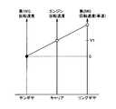
エンジン10、第1MG20および第2MG30が動力分割装置40によって連結されることにより、第1MG20の回転速度Nm1と、エンジン回転速度Neと、第2MG30の回転速度Nm2とは、図2の共線図上で1本の直線で結ばれる関係を維持するように各要素の回転速度Nm1,Ne,Nm2が変化する。 When
図2に示す共線図の三本の縦軸のうちの左側の縦軸がサンギヤ50の回転速度、すなわち、第1MG20の回転速度Nm1を示す。また、図2に示す共線図の中央の縦軸がキャリア54の回転速度、すなわち、エンジン回転速度Neを示す。また、図2に示す共線図の右側の縦軸がリングギヤ56の回転速度、すなわち、第2MG30の回転速度Nm2を示す。なお、図2の共線図の各縦軸の矢印の方向が正回転方向を示し、矢印の方向と逆方向が負回転方向を示す。 The left vertical axis of the three vertical axes in the alignment chart shown in FIG. 2 indicates the rotational speed of the
一例として、図2の実線に示すように、車両1が、第1MG20の回転速度Nm1がNm1(0)であって、エンジン回転速度NeがNe(0)であって、かつ、第2MG30の回転速度Nm2がNm2(0)であると想定する。 As an example, as indicated by the solid line in FIG. 2, the
動力分割装置40は、車両が走行し、かつエンジン10が停止した場合においても、第1MG20の回転軸を回転させる。車両1の高速走行中に車両1のシステムが停止状態にされた場合、エンジン10への燃料噴射を停止すると、エンジン回転速度Neはゼロになるように低下する。このとき、図2の破線に示すように、第1MG20の回転速度Nm1がNm1(0)からNm1(1)へと負回転方向に回転速度が増加する。したがって、車速が高いほど、エンジン回転速度Neがゼロになる場合の(エンジン10の回転が停止した場合の)第1MG20の回転速度Nm1がより高くなり得る。
車両1が走行中であって、エンジン回転速度Neがゼロである場合に、第1MG20を用いてエンジン10を始動させる場合を想定する。この場合、第1MG20の回転速度Nm1をNm1(1)(図2の破線)からNm1(0)(図2の実線)に引き上げることによって、エンジン回転速度Neを上昇させる必要がある。 It is assumed that the
第1MG20の回転速度をNm1(1)からNm1(0)まで上昇させるべく、第1MG20の回転方向(負回転方向)と反対の正回転方向のトルクを生じさせると、第1MG20が負回転方向に回転しているため、第1MG20は発電する。 In order to increase the rotation speed of the
このような発電は意図されたものではない。したがって、エンジン10を始動するときの発電を制限することが好ましい。そこで、本実施の形態においては、後述するように、走行中にエンジン10を停止したときの第1MG20の回転速度が制限される。 Such power generation is not intended. Therefore, it is preferable to limit power generation when starting the
図1に戻って、減速機58は、動力分割装置40や第2MG30からの動力を駆動輪80に伝達する。また、減速機58は、駆動輪80が受けた路面からの反力を動力分割装置40や第2MG30に伝達する。 Returning to FIG. 1, the
PCU60は、バッテリ70に蓄えられた直流電力を第1MG20および第2MG30を駆動するための交流電力に変換する。PCU60は、ECU200からの制御信号S2に基づいて制御されるコンバータおよびインバータ(いずれも図示せず)を含む。コンバータは、バッテリ70から受けた直流電力の電圧を昇圧してインバータに出力する。インバータは、コンバータが出力した直流電力を交流電力に変換して第1MG20および/または第2MG30に出力する。これにより、バッテリ70に蓄えられた電力を用いて第1MG20および/または第2MG30が駆動される。また、インバータは、第1MG20および/または第2MG30によって発電される交流電力を直流電力に変換してコンバータに出力する。コンバータは、インバータが出力した直流電力の電圧を降圧してバッテリ70へ出力する。これにより、第1MG20および/または第2MG30により発電された電力を用いてバッテリ70が充電される。なお、コンバータは、省略してもよい。 PCU 60 converts the DC power stored in
バッテリ70は、蓄電装置であり、再充電可能な直流電源である。バッテリ70としては、たとえば、ニッケル水素やリチウムイオン等の二次電池が用いられる。バッテリ70の電圧は、たとえば200V程度である。バッテリ70は、上述したように第1MG20および/または第2MG30により発電された電力を用いて充電される他、外部電源(図示せず)から供給される電力を用いて充電されてもよい。なお、バッテリ70は、二次電池に限らず、直流電圧を生成できるもの、たとえば、キャパシタ、太陽電池、燃料電池等であってもよい。 The
バッテリ70には、バッテリ70の電池温度TBを検出するための電池温度センサ156と、バッテリ70の電流IBを検出するための電流センサ158と、バッテリ70の電圧VBを検出するための電圧センサ160とが設けられる。 The
電池温度センサ156は、電池温度TBを示す信号をECU200に送信する。電流センサ158は、電流IBを示す信号をECU200に送信する。電圧センサ160は、電圧VBを示す信号をECU200に送信する。
スタートスイッチ150は、たとえば、プッシュ式スイッチである。スタートスイッチ150は、キーをキーシリンダに差し込んで所定の位置まで回転させるものであってもよい。スタートスイッチ150は、ECU200に接続される。運転者がスタートスイッチ150を操作することに応じて、スタートスイッチ150は、信号STをECU200に送信する。 The
ECU200は、たとえば、車両1のシステムが停止状態である場合に信号STを受信した場合に、起動指示を受けたと判断して、車両1のシステムを停止状態から起動状態に移行させる。また、ECU200は、車両1のシステムが起動状態である場合に信号STを受信した場合に、停止指示を受けた判断して、車両1のシステムを起動状態から停止状態に移行させる。以下の説明において、車両1のシステムが起動状態である場合に運転者がスタートスイッチ150を操作することをIGオフ操作といい、車両1のシステムが停止状態である場合に運転者がスタートスイッチ150を操作することをIGオン操作という。また、車両1のシステムが起動状態に移行した場合には、車両1が走行するために必要な複数の機器に電力が供給されるなどして、作動可能な状態となる。一方、車両1のシステムが停止状態に移行した場合には、車両1が走行するために必要な複数の機器のうちの一部への電力の供給が停止されるなどして、作動停止状態となる。 For example, when the signal ST is received when the system of the
第1レゾルバ12は、第1MG20の回転速度Nm1を検出する。第1レゾルバ12は、検出された回転速度Nm1を示す信号をECU200に送信する。第2レゾルバ13は、第2MG30の回転速度Nm2を検出する。第2レゾルバ13は、検出された回転速度Nm2を示す信号をECU200に送信する。 The first resolver 12 detects the rotational speed Nm1 of the
車輪速センサ14は、駆動輪80の回転速度Nwを検出する。車輪速センサ14は、検出された回転速度Nwを示す信号をECU200に送信する。ECU200は、受信した回転速度Nwに基づいて車速Vを算出する。なお、ECU200は、回転速度Nwに代えて第2MG30の回転速度Nm2に基づいて車速Vを算出するようにしてもよい。 The
制動装置151は、ブレーキアクチュエータ152と、ディスクブレーキ154とを含む。ディスクブレーキ154は、車輪と一体的に回転するブレーキディスクと、油圧を用いてブレーキディスクの回転を制限するブレーキキャリパとを含む。ブレーキキャリパは、ブレーキディスクを回転軸と平行な方向で挟み込むように設けられるブレーキパッドと、油圧をブレーキパッドに伝達するためのホイールシリンダとを含む。ブレーキアクチュエータ152は、ECU200から受信する制御信号S3に基づいて、運転者がブレーキペダルを踏み込むことによって発生する油圧と、ポンプおよび電磁弁等を用いて発生する油圧とを調整してホイールシリンダに供給される油圧を調整する。図1において、制動装置151は、後輪の右側にのみ図示されるが、制動装置151は、各車輪毎に設けられるものとする。
ECU200は、エンジン10を制御するための制御信号S1を生成し、その生成した制御信号S1をエンジン10へ出力する。また、ECU200は、PCU60を制御するための制御信号S2を生成し、その生成した制御信号S2をPCU60へ出力する。さらに、ECU200は、ブレーキアクチュエータ152を制御するための制御信号S3を生成し、その生成した制御信号S3をブレーキアクチュエータ152へ出力する。
ECU200は、エンジン10およびPCU60等を制御することによって車両1が最も効率よく運行できるようにハイブリッドシステム全体、すなわち、バッテリ70の充放電状態、エンジン10、第1MG20および第2MG30の動作状態を制御する。
ECU200は、運転席に設けられたアクセルペダル(図示せず)の踏込み量に対応する要求駆動力を算出する、ECU200は、算出された要求駆動力に応じて、第1MG20および第2MG30のトルクと、エンジン10の出力とを制御する。
上述したような構成を有する車両1においては、発進時や低速走行時等であってエンジン10の効率が悪い場合には、第2MG30のみによる走行が行なわれる。また、通常走行時には、たとえば動力分割装置40によりエンジン10の動力が2経路の動力に分けられる。一方の動力で駆動輪80が直接的に駆動される。他方の動力で第1MG20を駆動して発電が行なわれる。このとき、ECU200は、発電された電力を用いて第2MG30を駆動させる。このように第2MG30を駆動させることにより駆動輪80の駆動補助が行なわれる。 In the
車両1の減速時には、駆動輪80の回転に従動する第2MG30がジェネレータとして機能して回生制動が行なわれる。回生制動によって回収した電力は、バッテリ70に蓄えられる。なお、ECU200は、蓄電装置の残容量(以下の説明においては、SOC(State of Charge)と記載する)が低下し、充電が特に必要な場合には、エンジン10の出力を増加させて第1MG20による発電量を増加させる。これにより、バッテリ70のSOCが増加させられる。また、ECU200は、低速走行時でも必要に応じてエンジン10からの駆動力を増加させる制御を行なう場合もある。たとえば、上述のようにバッテリ70の充電が必要な場合や、エアコン等の補機が駆動される場合や、エンジン10の冷却水の温度を所定温度まで上げる場合等である。 When the
ECU200は、バッテリ70の充電量および放電量を制御する際に、電池温度TBおよび現在のSOCに基づいて、バッテリ70の充電時に許容される入力電力(以下の説明においては、「充電電力上限値Win」と記載する)およびバッテリ70の放電時に許容される出力電力(以下の説明においては、「放電電力上限値Wout」と記載する)を設定する。たとえば、現在のSOCが低下すると、放電電力上限値Woutは徐々に低く設定される。一方、現在のSOCが高くなると、充電電力上限値Winは徐々に低下するように設定される。 When controlling the amount of charge and the amount of discharge of the
また、バッテリ70として用いられる二次電池は、低温時に内部抵抗が上昇する温度依存性を有する。また、高温時には、さらなる発熱によって温度が過上昇することを防止する必要がある。このため、電池温度TBの低温時および高温時には、放電電力上限値Woutおよび充電電力上限値Winの各々を低下させることが好ましい。ECU200は、電池温度TBおよび現在SOCに応じて、たとえば、マップ等を用いることによって、充電電力上限値Winおよび放電電力上限値Woutを設定する。 Further, the secondary battery used as the
図3に、本実施の形態に係る車両1に搭載されたECU200の機能ブロック図を示す。ECU200は、判定部202と、停止部204と、制動部206とを含む。 FIG. 3 shows a functional block diagram of
判定部202は、IGオフ操作がされたか否かを判定する。判定部202は、たとえば車両1のシステムが起動状態である場合にスタートスイッチ150から信号STを受信した場合に、IGオフ操作がされたと判定する。なお、判定部202は、たとえば、IGオフ操作がされた場合にIGオフ判定フラグをオンするようにしてもよい。 The
さらに、判定部202は、車両1が走行中であるか否かを判定する。判定部202は、車速Vが所定車速V0よりも高い場合に、車両1が走行中であると判定する。なお、判定部202は、車両1が走行中であると判定された場合に走行判定フラグをオンするようにしてもよい。 Furthermore, the
停止部204は、IGオフ操作がされたと判定されると、すなわちスタートスイッチ150が運転者により操作されると、エンジン10を停止する。より具体的には、エンジン10を停止させるべく、燃料噴射ならびに点火が停止される。車両の走行中であっても、IGオフ操作がされると、エンジン10が停止される。 The
制動部206は、車両の走行中にIGオフ操作がされたと判定されると、すなわち車両の走行中にスタートスイッチ150が運転者により操作されると、サンギヤ50を制動するようにブレーキ22を制御する。したがって、車両の走行中にエンジン10が停止されると、サンギヤ50を制動するようにブレーキ22が制御される。ブレーキ22により、サンギヤ50が静止される。したがって、図4に示すように、第1MG20の回転速度がゼロまたは略ゼロに維持される。一方、車両が走行中であるため、リングギヤ56が回転されることによって、エンジン10の回転速度はゼロにならずに、エンジン10の出力軸が回転される。なお、第1MG20の回転速度がゼロでなくてもよい。 The
制動部206は、車速がしきい値V1よりも高い状態でスタートスイッチ150が操作されると、サンギヤ50を制動するようにブレーキ22を制御する。したがって、車速がしきい値V1以下の状態でスタッチスイッチ150が操作されても、サンギヤ50は制動されない。しきい値V1は、上述の所定車速V0よりも高い値である。 The
ブレーキ22によりサンギヤ50が制動された後、車速がしきい値V1以下まで低下すると、制動部206は、制動を停止するようにブレーキ22を制御する。また、ブレーキ22によりサンギヤ50が制動されてから予め定められた時間が経過すると、制動部206は、制動を停止するようにブレーキ22を制御する。スタートスイッチ150が操作されてから予め定められた時間が経過した場合、またはエンジン10が停止されてから(燃料噴射が停止されてから)予め定められた時間が経過した場合に、制動を停止するようにしてもよい。 After the
本実施の形態において、判定部202と、停止部204と、制動部206とは、いずれもECU200のCPUがメモリに記憶されたプログラムを実行することにより実現される、ソフトウェアとして機能するものとして説明するが、ハードウェアにより実現されるようにしてもよい。なお、このようなプログラムは記憶媒体に記録されて車両に搭載される。 In the present embodiment, the
図5を参照して、本実施の形態に係る車両1に搭載されたECU200で実行される処理について説明する。 With reference to FIG. 5, a process executed by
ステップ(以下、ステップをSと記載する)100にて、ECU200は、IGオフ操作がされたか否かを判定する。IGオフ操作がされた場合(S100にてYES)、S102にて、ECU200は、エンジン10を停止させる。すなわち、燃料噴射および点火が停止される。 In step (hereinafter, step is referred to as S) 100,
車両1が走行中である場合(S104にてYES)、S106にて、ECU200は、車速がしきい値V1より高いか否かを判定する。車速がしきい値V1より高いと(S106にてYES)、S108にて、ECU200は、サンギヤ50を制動するようにブレーキ22を制御する。 When
ブレーキ22によりサンギヤ50が制動された後、車速がしきい値V1以下まで低下した場合、または、予め定められた時間が経過した場合(S110にてYES)、S112にて、ECU200は、制動を停止するようにブレーキ22を制御する。したがって、ブレーキ22が解放され、サンギ50および第1MG20が回転可能になる。 When the vehicle speed decreases to a threshold value V1 or less after the
以上のように、本実施の形態によれば、車両の走行中にエンジン10が停止されると、サンギヤ50が制動される。これにより、第1MG20の回転数が制限される。 As described above, according to the present embodiment, when
今回開示された実施の形態はすべての点で例示であって制限的なものではないと考えられるべきである。本発明の範囲は上記した説明ではなくて請求の範囲によって示され、請求の範囲と均等の意味および範囲内でのすべての変更が含まれることが意図される。 The embodiment disclosed this time should be considered as illustrative in all points and not restrictive. The scope of the present invention is defined by the terms of the claims, rather than the description above, and is intended to include any modifications within the scope and meaning equivalent to the terms of the claims.
1 車両、10 エンジン、11 エンジン回転速度センサ、12 第1レゾルバ、13 第2レゾルバ、14 車輪速センサ、16 駆動軸、20 第1MG、22 ブレーキ、30 第2MG、40 動力分割装置、50 サンギヤ、52 ピニオンギヤ、54 キャリア、56 リングギヤ、58 減速機、70 バッテリ、80 駆動輪、102 気筒、104 燃料噴射装置、150 スタートスイッチ、156 電池温度センサ、158 電流センサ、160 電圧センサ、200 ECU、202 判定部、204 停止部、206 制動部。 DESCRIPTION OF
Claims (6)
Translated fromJapanese運転者がスイッチを操作するとエンジンを停止させる制御ユニットと、
前記車両の走行中に前記スイッチが操作されると、前記第1の回転要素を制動する制動装置とを備え、
前記制動装置は、車速がしきい値よりも低くなるまで低下すると、制動を停止する、車両。The first rotatingelement,a differentialequipment includinga third rotatingelement andour second rotatingelement,and an electricmotor coupledto the first rotatingelement, rotating the secondand engine coupledto the elements, a thirdvehicle and linked carwheel is providedon the rotatingelement of,
A controlunit that the driver stopsthe engine when operatingthe switch,
When theswitch is operated during running of the vehicle, anda brakingequipment for brakingsaid first rotaryelement,
The vehicle, wherein the braking device stops braking when the vehicle speed decreases to a value lower than a threshold value .
運転者がスイッチを操作するとエンジンを停止させる制御ユニットと、
前記車両の走行中に前記スイッチが操作されると、前記第1の回転要素を制動する制動装置とを備え、
前記制動装置は、車速がしきい値よりも高い状態で前記スイッチが操作されると、前記第1の回転要素を制動する、車両。A differential including a first rotating element, a second rotating element, and a third rotating element; an electric motor coupled to the first rotating element; and an engine coupled to the second rotating element A vehicle provided with wheels connected to the third rotating element,
A control unit that stops the engine when the driver operates the switch;
A brake device that brakes the first rotating element when the switch is operated while the vehicle is running;
The brakeequipment, when the vehicle speed is theswitch is operated in a state higher than the threshold, to brakethe first rotatingelement, a car both.
前記第2の回転要素はキャリアであって、
前記第3の回転要素はリングギヤである、請求項1〜3のいずれかに記載の車両。The first rotatingelement is a sun gear,
The second rotatingelement is a carrier,
The third rotatingelement is the ring gear, the vehicle according toany one of claims1-3.
運転者がスイッチを操作すると、エンジンを停止させるステップと、
前記車両の走行中に前記スイッチが操作されると、前記第1の回転要素を制動するステップと、
車速がしきい値よりも低くなるまで低下すると、制動を停止するステップとを備える、車両の制御方法。The first rotatingelement,a differentialequipment includinga third rotatingelement andour second rotatingelement,and an electricmotor coupledto the first rotatingelement, rotating the secondand engine coupledto the elements, a control method of the thirdvehicle and linked carwheel is providedon the rotatingelement of,
When the driver operatesthe switch, a step of stoppingthe engine,
When theswitch is operated during running of the vehicle, a step of brakingsaid first rotaryelement,
And a step of stopping braking when the vehicle speed decreases to a value lower than the threshold value .
運転者がスイッチを操作すると、エンジンを停止させるステップと、When the driver operates the switch, the step of stopping the engine;
前記車両の走行中に前記スイッチが操作されると、前記第1の回転要素を制動するステップと、Braking the first rotating element when the switch is operated during travel of the vehicle;
車速がしきい値よりも高い状態で前記スイッチが操作されると、前記第1の回転要素を制動するステップとを備える、車両の制御方法。And braking the first rotating element when the switch is operated in a state where the vehicle speed is higher than a threshold value.
Applications Claiming Priority (1)
| Application Number | Priority Date | Filing Date | Title |
|---|---|---|---|
| PCT/JP2011/051559WO2012101798A1 (en) | 2011-01-27 | 2011-01-27 | Vehicle, and vehicle control method |
Publications (2)
| Publication Number | Publication Date |
|---|---|
| JPWO2012101798A1 JPWO2012101798A1 (en) | 2014-06-30 |
| JP5644868B2true JP5644868B2 (en) | 2014-12-24 |
Family
ID=46580401
Family Applications (1)
| Application Number | Title | Priority Date | Filing Date |
|---|---|---|---|
| JP2012554580AActiveJP5644868B2 (en) | 2011-01-27 | 2011-01-27 | Vehicle and vehicle control method |
Country Status (5)
| Country | Link |
|---|---|
| US (1) | US9067584B2 (en) |
| JP (1) | JP5644868B2 (en) |
| CN (1) | CN103338957A (en) |
| DE (1) | DE112011104791B4 (en) |
| WO (1) | WO2012101798A1 (en) |
Families Citing this family (6)
| Publication number | Priority date | Publication date | Assignee | Title |
|---|---|---|---|---|
| US9216726B2 (en) | 2011-01-27 | 2015-12-22 | Toyota Jidosha Kabushiki Kaisha | Vehicle and control method for vehicle |
| JP6048266B2 (en)* | 2013-03-26 | 2016-12-21 | トヨタ自動車株式会社 | Hybrid vehicle drive device |
| JP5878495B2 (en) | 2013-06-11 | 2016-03-08 | 株式会社豊田中央研究所 | Electric vehicle power supply system |
| JP6380356B2 (en)* | 2015-12-03 | 2018-08-29 | トヨタ自動車株式会社 | Hybrid car |
| CN107867169A (en)* | 2016-09-28 | 2018-04-03 | 比亚迪股份有限公司 | Power-driven system and vehicle for vehicle |
| CN109996695B (en)* | 2016-11-30 | 2022-06-28 | 德纳有限公司 | Electric vehicle and hybrid electric vehicle electric axle transmission |
Citations (3)
| Publication number | Priority date | Publication date | Assignee | Title |
|---|---|---|---|---|
| JPH08308004A (en)* | 1995-04-28 | 1996-11-22 | Honda Motor Co Ltd | Control device for electric vehicle |
| JP2001065385A (en)* | 1999-08-25 | 2001-03-13 | Honda Motor Co Ltd | Control device for hybrid vehicle |
| JP2009067257A (en)* | 2007-09-13 | 2009-04-02 | Toyota Motor Corp | Control device for vehicle power transmission device |
Family Cites Families (33)
| Publication number | Priority date | Publication date | Assignee | Title |
|---|---|---|---|---|
| JP3668830B2 (en)* | 1998-08-28 | 2005-07-06 | トヨタ自動車株式会社 | Power transmission device and hybrid vehicle using the same |
| JP4236084B2 (en)* | 2002-08-09 | 2009-03-11 | アイシン・エィ・ダブリュ株式会社 | Hybrid vehicle drive control device, hybrid vehicle drive control method, and hybrid vehicle drive control program |
| JP3823949B2 (en)* | 2003-06-23 | 2006-09-20 | 日産自動車株式会社 | Hybrid vehicle mode transition control device |
| US6961646B2 (en)* | 2003-10-31 | 2005-11-01 | Ford Global Technologies, Llc | Automatic transmission control system with direct electronic swap-shift control |
| JP4464716B2 (en) | 2004-03-10 | 2010-05-19 | トヨタ自動車株式会社 | Drive system and automobile equipped with the same |
| JP4055725B2 (en)* | 2004-03-17 | 2008-03-05 | 日産自動車株式会社 | Hybrid vehicle mode transition control device |
| JP4155236B2 (en)* | 2004-07-09 | 2008-09-24 | トヨタ自動車株式会社 | Control device for vehicle drive device |
| JP4155244B2 (en)* | 2004-08-05 | 2008-09-24 | トヨタ自動車株式会社 | Control device for vehicle drive device |
| JP2007023919A (en) | 2005-07-19 | 2007-02-01 | Denso Corp | Engine start control system |
| JP4063295B2 (en)* | 2005-10-26 | 2008-03-19 | トヨタ自動車株式会社 | Control device for drive device for hybrid vehicle |
| JP2007216833A (en) | 2006-02-16 | 2007-08-30 | Toyota Motor Corp | Hybrid control device |
| JP4492585B2 (en)* | 2006-05-29 | 2010-06-30 | 日産自動車株式会社 | Hybrid vehicle control device and hybrid vehicle control method. |
| US7722498B2 (en)* | 2006-06-21 | 2010-05-25 | Denso Corporation | Control device and method for hybrid electric vehicle |
| US7490000B2 (en)* | 2006-08-29 | 2009-02-10 | Ford Motor Company | Fuel economy control system and control strategy |
| US7957881B2 (en)* | 2006-10-04 | 2011-06-07 | Toyota Jidosha Kabushiki Kaisha | Vehicle and method of controlling driving force for the vehicle based on detected slip of the drive wheel |
| KR101182222B1 (en) | 2006-10-20 | 2012-09-17 | 삼성전자주식회사 | Computer system and control method thereof |
| JP4179381B2 (en)* | 2007-01-25 | 2008-11-12 | トヨタ自動車株式会社 | Electric vehicle |
| JP4867687B2 (en) | 2007-02-07 | 2012-02-01 | トヨタ自動車株式会社 | INTERNAL COMBUSTION ENGINE DEVICE, ITS CONTROL METHOD, AND VEHICLE |
| JP5104169B2 (en) | 2007-09-28 | 2012-12-19 | トヨタ自動車株式会社 | Control device for vehicle power transmission device |
| JP4561812B2 (en)* | 2007-11-08 | 2010-10-13 | トヨタ自動車株式会社 | Control device for hybrid vehicle |
| JP5188783B2 (en) | 2007-11-14 | 2013-04-24 | アイシン・エィ・ダブリュ株式会社 | Vehicle drive system |
| JP5496454B2 (en)* | 2007-11-29 | 2014-05-21 | 日産自動車株式会社 | Control device for hybrid vehicle |
| JP2009149116A (en) | 2007-12-18 | 2009-07-09 | Toyota Motor Corp | Hybrid vehicle and control method thereof |
| JP2009280176A (en) | 2008-05-26 | 2009-12-03 | Toyota Motor Corp | Controller for vehicular power transmission device |
| JP4499170B2 (en) | 2008-05-27 | 2010-07-07 | トヨタ自動車株式会社 | VEHICLE, ITS CONTROL METHOD AND DRIVE DEVICE |
| JP4483989B2 (en)* | 2008-10-15 | 2010-06-16 | トヨタ自動車株式会社 | Hybrid vehicle |
| JP5171799B2 (en)* | 2008-12-18 | 2013-03-27 | 日産自動車株式会社 | Control device for belt type continuously variable transmission |
| JP5439126B2 (en) | 2009-03-31 | 2014-03-12 | 株式会社日立製作所 | Status detector for power supply |
| CN102143872B (en)* | 2009-05-27 | 2014-06-18 | 丰田自动车株式会社 | Apparatus and method for controlling drive of hybrid vehicle |
| CN102548820A (en)* | 2009-10-13 | 2012-07-04 | 本田技研工业株式会社 | Hybrid vehicle |
| CN103282255B (en) | 2010-12-24 | 2016-01-06 | 丰田自动车株式会社 | Vehicle and control method for vehicle |
| CN103282256A (en) | 2010-12-27 | 2013-09-04 | 丰田自动车株式会社 | Hybrid vehicle and control method therefor |
| JP5310715B2 (en) | 2010-12-28 | 2013-10-09 | ブラザー工業株式会社 | Image recording apparatus and program |
- 2011
- 2011-01-27DEDE112011104791.6Tpatent/DE112011104791B4/enactiveActive
- 2011-01-27JPJP2012554580Apatent/JP5644868B2/enactiveActive
- 2011-01-27USUS13/976,592patent/US9067584B2/enactiveActive
- 2011-01-27CNCN2011800657836Apatent/CN103338957A/enactivePending
- 2011-01-27WOPCT/JP2011/051559patent/WO2012101798A1/ennot_activeCeased
Patent Citations (3)
| Publication number | Priority date | Publication date | Assignee | Title |
|---|---|---|---|---|
| JPH08308004A (en)* | 1995-04-28 | 1996-11-22 | Honda Motor Co Ltd | Control device for electric vehicle |
| JP2001065385A (en)* | 1999-08-25 | 2001-03-13 | Honda Motor Co Ltd | Control device for hybrid vehicle |
| JP2009067257A (en)* | 2007-09-13 | 2009-04-02 | Toyota Motor Corp | Control device for vehicle power transmission device |
Also Published As
| Publication number | Publication date |
|---|---|
| JPWO2012101798A1 (en) | 2014-06-30 |
| DE112011104791T5 (en) | 2013-10-24 |
| WO2012101798A1 (en) | 2012-08-02 |
| CN103338957A (en) | 2013-10-02 |
| US9067584B2 (en) | 2015-06-30 |
| US20130297130A1 (en) | 2013-11-07 |
| DE112011104791B4 (en) | 2024-08-14 |
Similar Documents
| Publication | Publication Date | Title |
|---|---|---|
| JP5725037B2 (en) | Vehicle and vehicle control method | |
| US9796375B2 (en) | Control system for hybrid vehicle | |
| JP5729475B2 (en) | Vehicle and vehicle control method | |
| JP5652479B2 (en) | Vehicle and vehicle control method | |
| JP5598555B2 (en) | Vehicle and vehicle control method | |
| JP2010058579A (en) | Hybrid car | |
| JP2015098208A (en) | Hybrid vehicle | |
| JP5644868B2 (en) | Vehicle and vehicle control method | |
| JP5765419B2 (en) | Vehicle and vehicle control method | |
| JP5576336B2 (en) | Drive device and drive control method | |
| JP2011097666A (en) | Vehicle and control method therefor | |
| JP2008094238A (en) | Control device for hybrid vehicle | |
| JP5652546B2 (en) | Vehicle and vehicle control method | |
| JP2012162097A (en) | Vehicle | |
| JP2012224304A (en) | Damping control device of vehicle | |
| JP5810580B2 (en) | Vehicle and vehicle control method | |
| JPWO2012105019A1 (en) | Vehicle and vehicle control method | |
| JP2012236470A (en) | Damping control device of vehicle | |
| JP2013032096A (en) | Hybrid vehicle |
Legal Events
| Date | Code | Title | Description |
|---|---|---|---|
| A131 | Notification of reasons for refusal | Free format text:JAPANESE INTERMEDIATE CODE: A131 Effective date:20140715 | |
| A521 | Request for written amendment filed | Free format text:JAPANESE INTERMEDIATE CODE: A523 Effective date:20140820 | |
| TRDD | Decision of grant or rejection written | ||
| A01 | Written decision to grant a patent or to grant a registration (utility model) | Free format text:JAPANESE INTERMEDIATE CODE: A01 Effective date:20141007 | |
| A61 | First payment of annual fees (during grant procedure) | Free format text:JAPANESE INTERMEDIATE CODE: A61 Effective date:20141020 | |
| R151 | Written notification of patent or utility model registration | Ref document number:5644868 Country of ref document:JP Free format text:JAPANESE INTERMEDIATE CODE: R151 |