JP5643806B2 - Branch vessel prosthesis with roll-up seal assembly - Google Patents
Branch vessel prosthesis with roll-up seal assemblyDownload PDFInfo
- Publication number
- JP5643806B2 JP5643806B2JP2012502081AJP2012502081AJP5643806B2JP 5643806 B2JP5643806 B2JP 5643806B2JP 2012502081 AJP2012502081 AJP 2012502081AJP 2012502081 AJP2012502081 AJP 2012502081AJP 5643806 B2JP5643806 B2JP 5643806B2
- Authority
- JP
- Japan
- Prior art keywords
- prosthesis
- branch
- body portion
- assembly according
- configuration
- Prior art date
- Legal status (The legal status is an assumption and is not a legal conclusion. Google has not performed a legal analysis and makes no representation as to the accuracy of the status listed.)
- Expired - Fee Related
Links
- 239000000463materialSubstances0.000claimsdescription26
- 229910001000nickel titaniumInorganic materials0.000claimsdescription17
- HLXZNVUGXRDIFK-UHFFFAOYSA-Nnickel titaniumChemical compound[Ti].[Ti].[Ti].[Ti].[Ti].[Ti].[Ti].[Ti].[Ti].[Ti].[Ti].[Ni].[Ni].[Ni].[Ni].[Ni].[Ni].[Ni].[Ni].[Ni].[Ni].[Ni].[Ni].[Ni].[Ni]HLXZNVUGXRDIFK-UHFFFAOYSA-N0.000claimsdescription15
- 210000004204blood vesselAnatomy0.000claimsdescription11
- 229920001971elastomerPolymers0.000claimsdescription8
- 239000000806elastomerSubstances0.000claimsdescription8
- 238000003475laminationMethods0.000claimsdescription8
- 239000012528membraneSubstances0.000claimsdescription8
- 229920000295expanded polytetrafluoroethylenePolymers0.000claimsdescription6
- 239000005020polyethylene terephthalateSubstances0.000claimsdescription5
- 238000005470impregnationMethods0.000claimsdescription4
- 229920004934Dacron®Polymers0.000claimsdescription3
- 229920000728polyesterPolymers0.000claimsdescription2
- 229920001296polysiloxanePolymers0.000claimsdescription2
- 229920002635polyurethanePolymers0.000claimsdescription2
- 239000004814polyurethaneSubstances0.000claimsdescription2
- 238000007789sealingMethods0.000description79
- 238000000034methodMethods0.000description27
- 210000001367arteryAnatomy0.000description21
- 206010002329AneurysmDiseases0.000description19
- 210000002376aorta thoracicAnatomy0.000description13
- 239000012530fluidSubstances0.000description12
- 230000008569processEffects0.000description11
- 230000002792vascularEffects0.000description11
- 210000000709aortaAnatomy0.000description9
- 210000005166vasculatureAnatomy0.000description8
- 210000004369bloodAnatomy0.000description7
- 239000008280bloodSubstances0.000description7
- 229920000642polymerPolymers0.000description7
- 238000010586diagramMethods0.000description6
- 238000010438heat treatmentMethods0.000description6
- 238000002513implantationMethods0.000description6
- 229920001343polytetrafluoroethylenePolymers0.000description6
- 239000004810polytetrafluoroethyleneSubstances0.000description6
- 208000007474aortic aneurysmDiseases0.000description5
- 238000000465mouldingMethods0.000description5
- 210000000702aorta abdominalAnatomy0.000description4
- 230000017531blood circulationEffects0.000description4
- 238000011065in-situ storageMethods0.000description4
- 239000007788liquidSubstances0.000description4
- -1polytetrafluoroethylenePolymers0.000description4
- 210000003270subclavian arteryAnatomy0.000description4
- 201000008982Thoracic Aortic AneurysmDiseases0.000description3
- 230000036772blood pressureEffects0.000description3
- 210000001715carotid arteryAnatomy0.000description3
- 210000001168carotid artery commonAnatomy0.000description3
- 208000003457familial thoracic 1 aortic aneurysmDiseases0.000description3
- 230000003601intercostal effectEffects0.000description3
- 230000010412perfusionEffects0.000description3
- 210000002254renal arteryAnatomy0.000description3
- HZEWFHLRYVTOIW-UHFFFAOYSA-N[Ti].[Ni]Chemical compound[Ti].[Ni]HZEWFHLRYVTOIW-UHFFFAOYSA-N0.000description2
- WYTGDNHDOZPMIW-RCBQFDQVSA-NalstonineNatural productsC1=CC2=C3C=CC=CC3=NC2=C2N1C[C@H]1[C@H](C)OC=C(C(=O)OC)[C@H]1C2WYTGDNHDOZPMIW-RCBQFDQVSA-N0.000description2
- 239000004744fabricSubstances0.000description2
- 210000001105femoral arteryAnatomy0.000description2
- 230000006870functionEffects0.000description2
- 229910052751metalInorganic materials0.000description2
- 239000002184metalSubstances0.000description2
- 229920000139polyethylene terephthalatePolymers0.000description2
- 239000007787solidSubstances0.000description2
- 239000010935stainless steelSubstances0.000description2
- 229910001220stainless steelInorganic materials0.000description2
- 210000000115thoracic cavityAnatomy0.000description2
- 230000000472traumatic effectEffects0.000description2
- 238000003466weldingMethods0.000description2
- 238000004804windingMethods0.000description2
- 229910000531Co alloyInorganic materials0.000description1
- 239000004677NylonSubstances0.000description1
- 229920002614Polyether block amidePolymers0.000description1
- 239000004698PolyethyleneSubstances0.000description1
- RTAQQCXQSZGOHL-UHFFFAOYSA-NTitaniumChemical compound[Ti]RTAQQCXQSZGOHL-UHFFFAOYSA-N0.000description1
- 208000002223abdominal aortic aneurysmDiseases0.000description1
- 230000003187abdominal effectEffects0.000description1
- 210000003815abdominal wallAnatomy0.000description1
- 230000002159abnormal effectEffects0.000description1
- 230000001919adrenal effectEffects0.000description1
- 230000032683agingEffects0.000description1
- 210000003484anatomyAnatomy0.000description1
- 230000001174ascending effectEffects0.000description1
- 239000000560biocompatible materialSubstances0.000description1
- 238000001574biopsyMethods0.000description1
- 230000015572biosynthetic processEffects0.000description1
- 230000000740bleeding effectEffects0.000description1
- 210000001124body fluidAnatomy0.000description1
- 210000002434celiac arteryAnatomy0.000description1
- 238000003486chemical etchingMethods0.000description1
- 239000011248coating agentSubstances0.000description1
- 238000000576coating methodMethods0.000description1
- 239000002131composite materialSubstances0.000description1
- 238000002788crimpingMethods0.000description1
- 230000007423decreaseEffects0.000description1
- 230000000916dilatatory effectEffects0.000description1
- 230000010339dilationEffects0.000description1
- 201000010099diseaseDiseases0.000description1
- 208000037265diseases, disorders, signs and symptomsDiseases0.000description1
- KPUWHANPEXNPJT-UHFFFAOYSA-NdisiloxaneChemical class[SiH3]O[SiH3]KPUWHANPEXNPJT-UHFFFAOYSA-N0.000description1
- 230000000694effectsEffects0.000description1
- 230000007717exclusionEffects0.000description1
- 210000003090iliac arteryAnatomy0.000description1
- 238000003384imaging methodMethods0.000description1
- 230000001771impaired effectEffects0.000description1
- 239000007943implantSubstances0.000description1
- 238000003698laser cuttingMethods0.000description1
- 230000014759maintenance of locationEffects0.000description1
- 238000004519manufacturing processMethods0.000description1
- 238000010297mechanical methods and processMethods0.000description1
- 230000007246mechanismEffects0.000description1
- 150000002739metalsChemical class0.000description1
- 230000005012migrationEffects0.000description1
- 238000013508migrationMethods0.000description1
- 238000012986modificationMethods0.000description1
- 230000004048modificationEffects0.000description1
- 229920001778nylonPolymers0.000description1
- 238000002355open surgical procedureMethods0.000description1
- 210000000056organAnatomy0.000description1
- 210000005259peripheral bloodAnatomy0.000description1
- 239000011886peripheral bloodSubstances0.000description1
- 239000004033plasticSubstances0.000description1
- 229920003023plasticPolymers0.000description1
- 229920001692polycarbonate urethanePolymers0.000description1
- 229920000573polyethylenePolymers0.000description1
- 230000003014reinforcing effectEffects0.000description1
- 239000012779reinforcing materialSubstances0.000description1
- 230000000452restraining effectEffects0.000description1
- 150000003839saltsChemical class0.000description1
- 238000005476solderingMethods0.000description1
- 230000035882stressEffects0.000description1
- 229910052715tantalumInorganic materials0.000description1
- GUVRBAGPIYLISA-UHFFFAOYSA-Ntantalum atomChemical compound[Ta]GUVRBAGPIYLISA-UHFFFAOYSA-N0.000description1
- 238000005496temperingMethods0.000description1
- 239000010936titaniumSubstances0.000description1
- 229910052719titaniumInorganic materials0.000description1
- 238000002054transplantationMethods0.000description1
- 239000002759woven fabricSubstances0.000description1
Images


Classifications
- A—HUMAN NECESSITIES
- A61—MEDICAL OR VETERINARY SCIENCE; HYGIENE
- A61F—FILTERS IMPLANTABLE INTO BLOOD VESSELS; PROSTHESES; DEVICES PROVIDING PATENCY TO, OR PREVENTING COLLAPSING OF, TUBULAR STRUCTURES OF THE BODY, e.g. STENTS; ORTHOPAEDIC, NURSING OR CONTRACEPTIVE DEVICES; FOMENTATION; TREATMENT OR PROTECTION OF EYES OR EARS; BANDAGES, DRESSINGS OR ABSORBENT PADS; FIRST-AID KITS
- A61F2/00—Filters implantable into blood vessels; Prostheses, i.e. artificial substitutes or replacements for parts of the body; Appliances for connecting them with the body; Devices providing patency to, or preventing collapsing of, tubular structures of the body, e.g. stents
- A61F2/02—Prostheses implantable into the body
- A61F2/04—Hollow or tubular parts of organs, e.g. bladders, tracheae, bronchi or bile ducts
- A61F2/06—Blood vessels
- A61F2/064—Blood vessels with special features to facilitate anastomotic coupling
- A—HUMAN NECESSITIES
- A61—MEDICAL OR VETERINARY SCIENCE; HYGIENE
- A61F—FILTERS IMPLANTABLE INTO BLOOD VESSELS; PROSTHESES; DEVICES PROVIDING PATENCY TO, OR PREVENTING COLLAPSING OF, TUBULAR STRUCTURES OF THE BODY, e.g. STENTS; ORTHOPAEDIC, NURSING OR CONTRACEPTIVE DEVICES; FOMENTATION; TREATMENT OR PROTECTION OF EYES OR EARS; BANDAGES, DRESSINGS OR ABSORBENT PADS; FIRST-AID KITS
- A61F2/00—Filters implantable into blood vessels; Prostheses, i.e. artificial substitutes or replacements for parts of the body; Appliances for connecting them with the body; Devices providing patency to, or preventing collapsing of, tubular structures of the body, e.g. stents
- A61F2/02—Prostheses implantable into the body
- A61F2/04—Hollow or tubular parts of organs, e.g. bladders, tracheae, bronchi or bile ducts
- A61F2/06—Blood vessels
- A61F2/07—Stent-grafts
- D—TEXTILES; PAPER
- D04—BRAIDING; LACE-MAKING; KNITTING; TRIMMINGS; NON-WOVEN FABRICS
- D04C—BRAIDING OR MANUFACTURE OF LACE, INCLUDING BOBBIN-NET OR CARBONISED LACE; BRAIDING MACHINES; BRAID; LACE
- D04C1/00—Braid or lace, e.g. pillow-lace; Processes for the manufacture thereof
- D04C1/06—Braid or lace serving particular purposes
- A—HUMAN NECESSITIES
- A61—MEDICAL OR VETERINARY SCIENCE; HYGIENE
- A61F—FILTERS IMPLANTABLE INTO BLOOD VESSELS; PROSTHESES; DEVICES PROVIDING PATENCY TO, OR PREVENTING COLLAPSING OF, TUBULAR STRUCTURES OF THE BODY, e.g. STENTS; ORTHOPAEDIC, NURSING OR CONTRACEPTIVE DEVICES; FOMENTATION; TREATMENT OR PROTECTION OF EYES OR EARS; BANDAGES, DRESSINGS OR ABSORBENT PADS; FIRST-AID KITS
- A61F2/00—Filters implantable into blood vessels; Prostheses, i.e. artificial substitutes or replacements for parts of the body; Appliances for connecting them with the body; Devices providing patency to, or preventing collapsing of, tubular structures of the body, e.g. stents
- A61F2/82—Devices providing patency to, or preventing collapsing of, tubular structures of the body, e.g. stents
- A61F2/86—Stents in a form characterised by the wire-like elements; Stents in the form characterised by a net-like or mesh-like structure
- A61F2/89—Stents in a form characterised by the wire-like elements; Stents in the form characterised by a net-like or mesh-like structure the wire-like elements comprising two or more adjacent rings flexibly connected by separate members
- A—HUMAN NECESSITIES
- A61—MEDICAL OR VETERINARY SCIENCE; HYGIENE
- A61F—FILTERS IMPLANTABLE INTO BLOOD VESSELS; PROSTHESES; DEVICES PROVIDING PATENCY TO, OR PREVENTING COLLAPSING OF, TUBULAR STRUCTURES OF THE BODY, e.g. STENTS; ORTHOPAEDIC, NURSING OR CONTRACEPTIVE DEVICES; FOMENTATION; TREATMENT OR PROTECTION OF EYES OR EARS; BANDAGES, DRESSINGS OR ABSORBENT PADS; FIRST-AID KITS
- A61F2/00—Filters implantable into blood vessels; Prostheses, i.e. artificial substitutes or replacements for parts of the body; Appliances for connecting them with the body; Devices providing patency to, or preventing collapsing of, tubular structures of the body, e.g. stents
- A61F2/82—Devices providing patency to, or preventing collapsing of, tubular structures of the body, e.g. stents
- A61F2/86—Stents in a form characterised by the wire-like elements; Stents in the form characterised by a net-like or mesh-like structure
- A61F2/90—Stents in a form characterised by the wire-like elements; Stents in the form characterised by a net-like or mesh-like structure characterised by a net-like or mesh-like structure
- A—HUMAN NECESSITIES
- A61—MEDICAL OR VETERINARY SCIENCE; HYGIENE
- A61F—FILTERS IMPLANTABLE INTO BLOOD VESSELS; PROSTHESES; DEVICES PROVIDING PATENCY TO, OR PREVENTING COLLAPSING OF, TUBULAR STRUCTURES OF THE BODY, e.g. STENTS; ORTHOPAEDIC, NURSING OR CONTRACEPTIVE DEVICES; FOMENTATION; TREATMENT OR PROTECTION OF EYES OR EARS; BANDAGES, DRESSINGS OR ABSORBENT PADS; FIRST-AID KITS
- A61F2/00—Filters implantable into blood vessels; Prostheses, i.e. artificial substitutes or replacements for parts of the body; Appliances for connecting them with the body; Devices providing patency to, or preventing collapsing of, tubular structures of the body, e.g. stents
- A61F2/02—Prostheses implantable into the body
- A61F2/04—Hollow or tubular parts of organs, e.g. bladders, tracheae, bronchi or bile ducts
- A61F2/06—Blood vessels
- A61F2002/061—Blood vessels provided with means for allowing access to secondary lumens
- A—HUMAN NECESSITIES
- A61—MEDICAL OR VETERINARY SCIENCE; HYGIENE
- A61F—FILTERS IMPLANTABLE INTO BLOOD VESSELS; PROSTHESES; DEVICES PROVIDING PATENCY TO, OR PREVENTING COLLAPSING OF, TUBULAR STRUCTURES OF THE BODY, e.g. STENTS; ORTHOPAEDIC, NURSING OR CONTRACEPTIVE DEVICES; FOMENTATION; TREATMENT OR PROTECTION OF EYES OR EARS; BANDAGES, DRESSINGS OR ABSORBENT PADS; FIRST-AID KITS
- A61F2/00—Filters implantable into blood vessels; Prostheses, i.e. artificial substitutes or replacements for parts of the body; Appliances for connecting them with the body; Devices providing patency to, or preventing collapsing of, tubular structures of the body, e.g. stents
- A61F2/02—Prostheses implantable into the body
- A61F2/04—Hollow or tubular parts of organs, e.g. bladders, tracheae, bronchi or bile ducts
- A61F2/06—Blood vessels
- A61F2/07—Stent-grafts
- A61F2002/072—Encapsulated stents, e.g. wire or whole stent embedded in lining
- A—HUMAN NECESSITIES
- A61—MEDICAL OR VETERINARY SCIENCE; HYGIENE
- A61F—FILTERS IMPLANTABLE INTO BLOOD VESSELS; PROSTHESES; DEVICES PROVIDING PATENCY TO, OR PREVENTING COLLAPSING OF, TUBULAR STRUCTURES OF THE BODY, e.g. STENTS; ORTHOPAEDIC, NURSING OR CONTRACEPTIVE DEVICES; FOMENTATION; TREATMENT OR PROTECTION OF EYES OR EARS; BANDAGES, DRESSINGS OR ABSORBENT PADS; FIRST-AID KITS
- A61F2/00—Filters implantable into blood vessels; Prostheses, i.e. artificial substitutes or replacements for parts of the body; Appliances for connecting them with the body; Devices providing patency to, or preventing collapsing of, tubular structures of the body, e.g. stents
- A61F2/02—Prostheses implantable into the body
- A61F2/04—Hollow or tubular parts of organs, e.g. bladders, tracheae, bronchi or bile ducts
- A61F2/06—Blood vessels
- A61F2/07—Stent-grafts
- A61F2002/075—Stent-grafts the stent being loosely attached to the graft material, e.g. by stitching
- A—HUMAN NECESSITIES
- A61—MEDICAL OR VETERINARY SCIENCE; HYGIENE
- A61F—FILTERS IMPLANTABLE INTO BLOOD VESSELS; PROSTHESES; DEVICES PROVIDING PATENCY TO, OR PREVENTING COLLAPSING OF, TUBULAR STRUCTURES OF THE BODY, e.g. STENTS; ORTHOPAEDIC, NURSING OR CONTRACEPTIVE DEVICES; FOMENTATION; TREATMENT OR PROTECTION OF EYES OR EARS; BANDAGES, DRESSINGS OR ABSORBENT PADS; FIRST-AID KITS
- A61F2/00—Filters implantable into blood vessels; Prostheses, i.e. artificial substitutes or replacements for parts of the body; Appliances for connecting them with the body; Devices providing patency to, or preventing collapsing of, tubular structures of the body, e.g. stents
- A61F2/82—Devices providing patency to, or preventing collapsing of, tubular structures of the body, e.g. stents
- A61F2002/821—Ostial stents
- A—HUMAN NECESSITIES
- A61—MEDICAL OR VETERINARY SCIENCE; HYGIENE
- A61F—FILTERS IMPLANTABLE INTO BLOOD VESSELS; PROSTHESES; DEVICES PROVIDING PATENCY TO, OR PREVENTING COLLAPSING OF, TUBULAR STRUCTURES OF THE BODY, e.g. STENTS; ORTHOPAEDIC, NURSING OR CONTRACEPTIVE DEVICES; FOMENTATION; TREATMENT OR PROTECTION OF EYES OR EARS; BANDAGES, DRESSINGS OR ABSORBENT PADS; FIRST-AID KITS
- A61F2/00—Filters implantable into blood vessels; Prostheses, i.e. artificial substitutes or replacements for parts of the body; Appliances for connecting them with the body; Devices providing patency to, or preventing collapsing of, tubular structures of the body, e.g. stents
- A61F2/82—Devices providing patency to, or preventing collapsing of, tubular structures of the body, e.g. stents
- A61F2/848—Devices providing patency to, or preventing collapsing of, tubular structures of the body, e.g. stents having means for fixation to the vessel wall, e.g. barbs
- A61F2002/8486—Devices providing patency to, or preventing collapsing of, tubular structures of the body, e.g. stents having means for fixation to the vessel wall, e.g. barbs provided on at least one of the ends
- A—HUMAN NECESSITIES
- A61—MEDICAL OR VETERINARY SCIENCE; HYGIENE
- A61F—FILTERS IMPLANTABLE INTO BLOOD VESSELS; PROSTHESES; DEVICES PROVIDING PATENCY TO, OR PREVENTING COLLAPSING OF, TUBULAR STRUCTURES OF THE BODY, e.g. STENTS; ORTHOPAEDIC, NURSING OR CONTRACEPTIVE DEVICES; FOMENTATION; TREATMENT OR PROTECTION OF EYES OR EARS; BANDAGES, DRESSINGS OR ABSORBENT PADS; FIRST-AID KITS
- A61F2220/00—Fixations or connections for prostheses classified in groups A61F2/00 - A61F2/26 or A61F2/82 or A61F9/00 or A61F11/00 or subgroups thereof
- A61F2220/0025—Connections or couplings between prosthetic parts, e.g. between modular parts; Connecting elements
- A61F2220/0058—Connections or couplings between prosthetic parts, e.g. between modular parts; Connecting elements soldered or brazed or welded
- A—HUMAN NECESSITIES
- A61—MEDICAL OR VETERINARY SCIENCE; HYGIENE
- A61F—FILTERS IMPLANTABLE INTO BLOOD VESSELS; PROSTHESES; DEVICES PROVIDING PATENCY TO, OR PREVENTING COLLAPSING OF, TUBULAR STRUCTURES OF THE BODY, e.g. STENTS; ORTHOPAEDIC, NURSING OR CONTRACEPTIVE DEVICES; FOMENTATION; TREATMENT OR PROTECTION OF EYES OR EARS; BANDAGES, DRESSINGS OR ABSORBENT PADS; FIRST-AID KITS
- A61F2240/00—Manufacturing or designing of prostheses classified in groups A61F2/00 - A61F2/26 or A61F2/82 or A61F9/00 or A61F11/00 or subgroups thereof
- A61F2240/001—Designing or manufacturing processes
- A—HUMAN NECESSITIES
- A61—MEDICAL OR VETERINARY SCIENCE; HYGIENE
- A61F—FILTERS IMPLANTABLE INTO BLOOD VESSELS; PROSTHESES; DEVICES PROVIDING PATENCY TO, OR PREVENTING COLLAPSING OF, TUBULAR STRUCTURES OF THE BODY, e.g. STENTS; ORTHOPAEDIC, NURSING OR CONTRACEPTIVE DEVICES; FOMENTATION; TREATMENT OR PROTECTION OF EYES OR EARS; BANDAGES, DRESSINGS OR ABSORBENT PADS; FIRST-AID KITS
- A61F2250/00—Special features of prostheses classified in groups A61F2/00 - A61F2/26 or A61F2/82 or A61F9/00 or A61F11/00 or subgroups thereof
- A61F2250/0014—Special features of prostheses classified in groups A61F2/00 - A61F2/26 or A61F2/82 or A61F9/00 or A61F11/00 or subgroups thereof having different values of a given property or geometrical feature, e.g. mechanical property or material property, at different locations within the same prosthesis
- A61F2250/0039—Special features of prostheses classified in groups A61F2/00 - A61F2/26 or A61F2/82 or A61F9/00 or A61F11/00 or subgroups thereof having different values of a given property or geometrical feature, e.g. mechanical property or material property, at different locations within the same prosthesis differing in diameter
- A—HUMAN NECESSITIES
- A61—MEDICAL OR VETERINARY SCIENCE; HYGIENE
- A61F—FILTERS IMPLANTABLE INTO BLOOD VESSELS; PROSTHESES; DEVICES PROVIDING PATENCY TO, OR PREVENTING COLLAPSING OF, TUBULAR STRUCTURES OF THE BODY, e.g. STENTS; ORTHOPAEDIC, NURSING OR CONTRACEPTIVE DEVICES; FOMENTATION; TREATMENT OR PROTECTION OF EYES OR EARS; BANDAGES, DRESSINGS OR ABSORBENT PADS; FIRST-AID KITS
- A61F2250/00—Special features of prostheses classified in groups A61F2/00 - A61F2/26 or A61F2/82 or A61F9/00 or A61F11/00 or subgroups thereof
- A61F2250/0058—Additional features; Implant or prostheses properties not otherwise provided for
- A61F2250/006—Additional features; Implant or prostheses properties not otherwise provided for modular
- D—TEXTILES; PAPER
- D10—INDEXING SCHEME ASSOCIATED WITH SUBLASSES OF SECTION D, RELATING TO TEXTILES
- D10B—INDEXING SCHEME ASSOCIATED WITH SUBLASSES OF SECTION D, RELATING TO TEXTILES
- D10B2509/00—Medical; Hygiene
- D10B2509/06—Vascular grafts; stents
Landscapes
- Health & Medical Sciences (AREA)
- Engineering & Computer Science (AREA)
- Heart & Thoracic Surgery (AREA)
- Vascular Medicine (AREA)
- Oral & Maxillofacial Surgery (AREA)
- Transplantation (AREA)
- Pulmonology (AREA)
- Biomedical Technology (AREA)
- Gastroenterology & Hepatology (AREA)
- Cardiology (AREA)
- Life Sciences & Earth Sciences (AREA)
- Animal Behavior & Ethology (AREA)
- General Health & Medical Sciences (AREA)
- Public Health (AREA)
- Veterinary Medicine (AREA)
- Manufacturing & Machinery (AREA)
- Textile Engineering (AREA)
- Prostheses (AREA)
Description
Translated fromJapanese本発明は、概略的には、管腔内医療デバイスおよび医学的処置に関し、より詳細には、主血管プロテーゼとの流体密封を作成するための巻き上げ式フランジを有する分岐血管プロテーゼに関する。 The present invention relates generally to endoluminal medical devices and medical procedures, and more particularly to a branch vessel prosthesis having a roll-up flange for creating a fluid seal with the main vessel prosthesis.
生体の血管または他の類似する器官における移植のためのプロテーゼは、一般的に、医療技術で公知である。例えば、損傷または閉塞した血管を置換またはバイパスするために、Dacronまたは拡張多孔質ポリテトラフルオロエチレン(PTFE)チューブ材料等の生体適合性材料で構成される、血管グラフトプロテーゼが採用されてきた。一般的に、血管内グラフトは、典型的に、血管内のその意図する位置に管状グラフトを保持するように機能する、グラフト固定構成要素を含む。最も一般的には、グラフト固定構成要素は、管状グラフトを血管または解剖学的な管路の壁に固定するように現場で半径方向に拡張させられる、1つまたは複数の半径方向に圧縮可能なステントである。したがって、血管内グラフトは、典型的に、拡張可能なステントによって提供される反対方向の力による機械的係合および摩擦によって適所に保持される。 Prostheses for transplantation in living blood vessels or other similar organs are generally known in the medical arts. For example, vascular graft prostheses composed of biocompatible materials such as Dacron or expanded porous polytetrafluoroethylene (PTFE) tubing have been employed to replace or bypass damaged or occluded blood vessels. In general, an endovascular graft typically includes a graft fixation component that functions to hold the tubular graft in its intended location within the blood vessel. Most commonly, the graft fixation component is one or more radially compressible that is radially expanded in situ to secure the tubular graft to the vessel or anatomical duct wall. It is a stent. Thus, the endovascular graft is typically held in place by mechanical engagement and friction due to the opposing forces provided by the expandable stent.
一般的に、ステントグラフトは、外傷的かつ侵襲的である開放手術処置を実施してグラフトを移植するのではなく、好ましくは、侵襲性の低い管腔内送達を通して展開する。より具体的には、好都合かつ外傷性の低い入口点で脈管構造の管腔にアクセスし、圧縮されたステントグラフトを、該脈管構造を通して、プロテーゼを展開する場所まで送る。自己拡張デバイスを管腔内で展開することは、典型的に、相対的な軸方向移動のために配設される外側チューブおよび内側チューブを備えた送達カテーテルを使用して行われる。例えば、自己拡張ステントグラフトは、内側部材に固定されたストッパの遠位の外側カテーテルチューブの遠位端内に圧縮されて配置されてもよい。次いで、ステントグラフトを含有するカテーテルの端部が意図する治療部位に位置決めされるまで、体内管腔を通してカテーテルが送られる。次いで、内側部材上のストッパは、送達カテーテルの外側チューブが引き抜かれる間、静止状態に保持される。ストッパは、ステントグラフトがシースとともに引き抜かれるのを防止する。シースが引き抜かれるにつれて、ステントグラフトは、シースの閉じ込めから開放されて、半径方向に自己拡張し、その結果、ステントグラフトの少なくとも一部分が、例えば血管壁または解剖学的な管路といった、管腔を囲む内壁の一部分に接触して実質的に合致する。 In general, stent grafts are preferably deployed through less invasive intraluminal delivery, rather than performing an open surgical procedure that is traumatic and invasive to implant the graft. More specifically, the lumen of the vasculature is accessed at a convenient and less traumatic entry point and the compressed stent graft is routed through the vasculature to where the prosthesis is deployed. Deploying the self-expanding device within the lumen is typically performed using a delivery catheter with an outer tube and an inner tube that are arranged for relative axial movement. For example, the self-expanding stent graft may be compressed and placed within the distal end of the outer catheter tube distal to the stopper secured to the inner member. The catheter is then advanced through the body lumen until the end of the catheter containing the stent graft is positioned at the intended treatment site. The stopper on the inner member is then held stationary while the outer tube of the delivery catheter is withdrawn. The stopper prevents the stent graft from being pulled out with the sheath. As the sheath is withdrawn, the stent-graft is released from the sheath containment and self-expands radially, so that at least a portion of the stent-graft is an inner wall that surrounds the lumen, for example, a vessel wall or an anatomical duct In contact with and substantially conforms to a portion of
グラフト処置はまた、動脈瘤を治療するためのものであることも公知である。動脈瘤は、血管の老化、疾病、および/または血圧により、脆く、薄くなった血管壁が「膨らむ」または拡張することに起因する。その結果、動脈瘤の血管が破裂する可能性が生じ、内出血および潜在的に生命に関わる状態を引き起こす。グラフトは、しばしば、動脈瘤または他の正常血圧からの血管の異常状態を分離するために使用され、脆くなった血管壁への圧力を低減して、血管が破裂する可能性を低減する。このように、管状血管内グラフトは、動脈瘤を通しての人工的な流れ管路を作成するように、動脈瘤の血管内に配置されてもよく、それによって、ほぼ排除できないとしても、血圧が動脈瘤に作用するのを低減する。 Grafting procedures are also known to treat aneurysms. Aneurysms result from the bulging and dilation of vascular walls that are fragile and thin due to vascular aging, disease, and / or blood pressure. As a result, the aneurysm's blood vessels can rupture, causing internal bleeding and potentially life-threatening conditions. Grafts are often used to isolate an abnormal condition of a blood vessel from an aneurysm or other normal blood pressure, reducing the pressure on the fragile vessel wall and reducing the likelihood that the vessel will rupture. In this way, the tubular endovascular graft may be placed within the aneurysm vessel to create an artificial flow line through the aneurysm, thereby allowing blood pressure to be arterial even though it cannot be nearly eliminated. Reduces the effect on the aneurysm.
動脈瘤は、あらゆる血管で生じる可能性があるが、ほとんどは大動脈および末梢血管で生じる。動脈瘤は、関与する大動脈の領域に応じて、血管分岐部、すなわちそこからより小さい「分岐」動脈が延在する大動脈分節を有する領域の中に延在する場合がある。種々の種類の大動脈瘤は、動脈瘤が関与する領域に基づいて分類されてもよい。例えば、胸部大動脈瘤は、上行胸部大動脈、大動脈弓、およびそこから生じる鎮骨下動脈等の分岐動脈の中に現れる動脈瘤を含み、また、下行胸部大動脈、およびそこから生じる胸部肋間動脈等の分岐動脈、ならびに/または副腎腹部大動脈、およびそこから生じる上腸間膜動脈、腹腔動脈、ならびに/または肋間動脈等の分岐動脈の中に現れる動脈瘤も含む。最後に、腹部大動脈瘤は、例えば腎傍大動脈、およびそこから生じる腎動脈等の分岐動脈といった、横隔膜より下側の大動脈の中に現れる動脈瘤を含む。 Aneurysms can occur in any blood vessel, but most occur in the aorta and peripheral blood vessels. Depending on the area of the aorta involved, the aneurysm may extend into a vessel bifurcation, ie, an area having an aortic segment from which a smaller “branch” artery extends. Various types of aortic aneurysms may be classified based on the area in which the aneurysm is involved. For example, a thoracic aortic aneurysm includes an aneurysm that appears in a branching artery such as the ascending thoracic aorta, the aortic arch, and the subosseous artery that results therefrom, and the descending thoracic aorta and the thoracic intercostal artery that results therefrom. Also included are bifurcated arteries and / or aneurysms that appear in the branch arteries such as the adrenal abdominal aorta and the superior mesenteric, celiac, and / or intercostal arteries arising therefrom. Finally, abdominal aortic aneurysms include aneurysms that appear in the aorta below the diaphragm, such as, for example, the pararenal aorta and branching arteries such as the renal artery that arise therefrom.
残念なことに、大動脈瘤と診断された全ての患者が、直ちに血管内グラフトの候補とみなされるわけではない。これは、従来の技術の血管内グラフト系の大部分が、そこから側枝が延在する大動脈の領域の中で使用するように設計されていないという事実に起因するところが大きい。そのような場合は、分岐動脈の中への血流を損なわない様態で、血管内グラフトを設計し、移植し、そして維持しなければならないので、そこから分岐動脈が延在する大動脈の領域内で血管内グラフトを展開することは、さらなる技術的な問題を提示する。 Unfortunately, not all patients diagnosed with an aortic aneurysm are immediately considered candidates for endovascular grafts. This is largely due to the fact that most of the prior art endovascular graft systems are not designed for use in the region of the aorta from which the side branch extends. In such cases, the endovascular graft must be designed, transplanted, and maintained in a manner that does not impair blood flow into the branch artery, and therefore within the region of the aorta from which the branch artery extends. Deploying endovascular grafts presents additional technical problems.
側枝に適応させるために、しばしば、その側壁に開窓または開口部を有する主血管ステントグラフトが利用される。開窓は、展開後に、分岐血管の小孔と整合するように位置決めされる。使用の際に、1つまたは複数の側開口部を有するグラフトの近位端は、適所に確実に固定され、開窓または開口部は、側枝の中への血流を遮断または制限するのを回避するように構成および展開される。開窓は、単独では、そこを通して血液が各側枝動脈に向けられる離散管路を形成しない。その結果、開窓を囲むグラフトの縁部は、i)大動脈グラフトの外面とそれを囲む大動脈壁との間の空間の中への血液の漏出、またはii)開窓と分岐動脈との整合不良を引き起こし、分岐動脈の中への流れの障害をもたらす、移植後のステントグラフトの転位または移動を起こしやすい。 To accommodate the side branches, main vessel stent grafts with fenestrations or openings in their side walls are often utilized. The fenestration is positioned to align with the ostium of the branch vessel after deployment. In use, the proximal end of the graft having one or more side openings is securely fixed in place, and the fenestration or opening blocks or restricts blood flow into the side branch. Configured and deployed to avoid. A fenestration alone does not form a discrete line through which blood is directed to each side branch artery. As a result, the edge of the graft surrounding the fenestration is either i) leakage of blood into the space between the outer surface of the aortic graft and the surrounding aortic wall, or ii) misalignment between the fenestration and the branch artery. And is prone to dislocation or migration of the stent-graft after implantation, resulting in impaired flow into the branch artery.
ある場合には、次いで、分岐血管に流れる血液のための管路を提供するように、しばしば分岐グラフトと称される別のステントグラフトを、開窓を通して分岐血管の中で展開することがある。分岐グラフトは、好ましくは、不要な漏出を防止するように、現場で主グラフトに密封状態で接続される。 In some cases, another stent graft, often referred to as a branch graft, may then be deployed in the branch vessel through the fenestration to provide a conduit for blood flowing into the branch vessel. The branch graft is preferably hermetically connected to the main graft in situ to prevent unwanted leakage.
分岐グラフトを展開して、密封することが特に難しい領域は、大動脈弓である。胸部大動脈瘤(TAA)を伴う患者の大部分には、大動脈弓の分岐の遠位にステントグラフトを固定して、密封するための健常な血管組織が存在しない。したがって、大動脈弓の中で展開するステントグラフトは、1つまたは複数の分岐動脈を横断するように架かる。 An area where the branch graft is particularly difficult to deploy and seal is the aortic arch. Most patients with thoracic aortic aneurysm (TAA) do not have healthy vascular tissue to secure and seal the stent graft distal to the bifurcation of the aortic arch. Thus, a stent graft that deploys within the aortic arch spans one or more branch arteries.
したがって、この技術には、開窓から対応する分岐血管に流れを方向付けるための改善に対する必要性が残る。本明細書の実施形態は、側枝血管プロテーゼと主血管内に移植されるプロテーゼとの間に血液密封を提供するように、可搬式の弾性密封アセンブリを有する側枝プロテーゼに関する。密封アセンブリは、予め開窓のあるグラフトまたは現場で作成される開窓を有するグラフトとともに利用されてもよい。 Thus, there remains a need in the art for improvements to direct flow from the fenestration to the corresponding branch vessel. Embodiments herein relate to a side branch prosthesis having a portable elastic sealing assembly to provide a blood seal between the side branch vascular prosthesis and the prosthesis implanted in the main vessel. The sealing assembly may be utilized with a pre-glazed graft or a graft with a fenestration created in situ.
側枝管腔内プロテーゼは、第1の外径を備え拡張可能な本体部分を含み、該本体部分は、近位端と遠位端とを有する。分岐プロテーゼはまた、本体部分に近位端に取り付けられた拡張可能なフランジも含み、該フランジは、第1の外径よりも大きい第2の外径を有し、密封スリーブは、拡張可能なフランジから近位に延在する。密封スリーブは、移植中に第1の構成に変形し、移植後に第2の構成に展開するように構成されている。密封スリーブは、第1の構成では、標的部位に送達するのに十分なロープロファイル形態を有する、略直円筒の中空形状である。密封スリーブは、第2の構成では、環状フランジを担持する密に巻回されたコイルに巻き上がる。 The side branch endoluminal prosthesis includes an expandable body portion having a first outer diameter, the body portion having a proximal end and a distal end. The branch prosthesis also includes an expandable flange attached to the body portion at a proximal end, the flange having a second outer diameter that is greater than the first outer diameter, and the sealing sleeve is expandable. Extends proximally from the flange. The sealing sleeve is configured to deform to a first configuration during implantation and to deploy to a second configuration after implantation. The sealing sleeve, in the first configuration, is a generally right cylindrical hollow shape having a low profile configuration sufficient for delivery to a target site. The sealing sleeve, in the second configuration, winds up on a tightly wound coil carrying an annular flange.
側枝プロテーゼは、分岐血管の中に配置するために構成され、かつ側開口部を有し、主血管内で展開する主血管プロテーゼとともに使用するために構成される。環状フランジは、展開した時に、側開口部の外辺部の周囲で主血管プロテーゼの外面に係合し、巻き上げられた密封スリーブは、側開口部の外辺部の周囲で主プロテーゼの内面に係合して、主血管プロテーゼと分岐血管プロテーゼとの間で流体密封を形成する。
本発明による実施形態の前述した、ならびに他の特徴および利点は、添付図面に示されるように、以下の説明から明白になるであろう。本明細書に組み込まれ、本明細書の一部を形成する添付図面はさらに、実施形態の原理を説明し、当業者が本明細書に記載された実施形態を製作し、使用することを可能にするのに役立つ。図面は、原寸大ではない。The side branch prosthesis is configured for placement in a branch vessel and is configured for use with a main vessel prosthesis having a side opening and deploying within the main vessel. The annular flange, when deployed, engages the outer surface of the main vascular prosthesis around the outer edge of the side opening, and the rolled up sealing sleeve surrounds the inner surface of the main prosthesis around the outer edge of the side opening. Engage to form a fluid seal between the main vascular prosthesis and the branch vascular prosthesis.
The foregoing and other features and advantages of embodiments according to the present invention will become apparent from the following description, as illustrated in the accompanying drawings. The accompanying drawings, which are incorporated in and form a part of this specification, further illustrate the principles of the embodiments and enable those skilled in the art to make and use the embodiments described herein. To help. The drawings are not to scale.
以下、図面を参照して具体的な実施形態を説明するが、同様の参照番号は、同一の要素または機能的に類似した要素を示す。特に明記しない限り、分岐プロテーゼ100等の本明細書に記載する血管内プロテーゼに関して、「遠位」および「近位」という用語は、以下の説明では、心臓に対する位置または方向について使用される。「遠位」および「遠位に」とは、血液の流路に関して心臓から遠い位置、または心臓から離れる方向であり、「近位」および「近位に」とは、血液の流路に関して心臓に近い位置、または心臓に向かう方向である。本明細書に記載する送達系に関して、「遠位」および「近位」という用語は、以下の説明では、臨床医に対する位置または方向について使用される。「遠位」および「遠位に」とは、臨床医から遠い位置、または臨床医から離れる方向であり、「近位」および「近位に」とは、臨床医に近い位置、または臨床医に向かう方向である。 Hereinafter, specific embodiments will be described with reference to the drawings, wherein like reference numerals indicate identical or functionally similar elements. Unless otherwise stated, with respect to the endovascular prostheses described herein, such as
以下の発明を実施するための形態は、本質的に単なる例示に過ぎない。この説明は、そこから分岐血管(例えば、頸動脈、腕頭動脈、鎖骨下動脈、肋間動脈、上腹壁動脈、腹腔動脈、腎動脈、または腸骨動脈)が延在する血管(例えば、大動脈)の治療という文脈であるが、本実施形態はまた、該実施形態が有用であると考えられる、あらゆる他の体内通路の中で使用してもよい。さらに、前述の技術分野、背景、発明の開示、または後述の発明を実施するための最良の形態に示される、あらゆる表現または暗黙的な理論によって制限されることを意図するものではない。 The following modes for carrying out the invention are merely illustrative in nature. This description refers to a blood vessel (eg, aorta) from which a branch vessel (eg, carotid artery, brachiocephalic artery, subclavian artery, intercostal artery, superior abdominal wall artery, celiac artery, renal artery, or iliac artery) extends. In this context, this embodiment may also be used in any other body passage in which the embodiment would be useful. Furthermore, there is no intention to be bound by any expressed or implied theory presented in the preceding technical field, background, disclosure of the invention or the best mode for carrying out the invention described below.
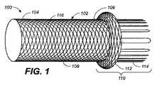
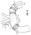
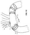
図1〜図3を参照すると、分岐血管の中に配置するために構成されるプロテーゼ100は、遠位端部分104と近位端部分106との間に延在する、外径108を有する本体部分102を含む。分岐プロテーゼ100は、近位端部分106に取り付けられる、密封アセンブリ110を含む。密封アセンブリ110は、拡張可能な環状フランジ112と、環状フランジ112から近位に延在する密封スリーブ114とを含む。密封スリーブ114は、移植中に第1の構成に変形し、移植中に第2の構成に展開するように構成されている。スリーブ114第1の構成(図1に示す)は、略直円筒の中空形状である。図1は、展開していない構成の密封スリーブ114を示す一方で、図2は、第2の構成に展開し始めた時の密封スリーブ114を示す。密封スリーブ114は、完全に展開した時に、図3に示されるように、環状フランジ112を担持する密に巻回された環状コイルに巻き上がる。本明細書でさらに詳細に説明するように、密封アセンブリ110は、主血管内で展開し、側開口部または開窓を有する主プロテーゼとともに使用された時に、分岐プロテーゼ100と主プロテーゼとの間に流体密封を形成する。 With reference to FIGS. 1-3, a
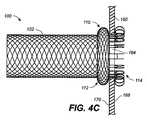
より具体的には、ここで図4A〜図4Cを参照すると、環状フランジ112は、開窓164の外辺部の周囲で主プロテーゼ160の外面170に係合するように展開し、密封スリーブ114は、開窓164の外辺部の周囲で主プロテーゼ160の内面168に係合するように展開し、したがって、主プロテーゼ160と分岐プロテーゼ100との間で、常に負荷のかかるガスケット型の密封を形成する。密封スリーブ114は、主プロテーゼ160の材料を捕捉し、それを環状フランジ112に押圧して、したがって、弾性密封アセンブリ110を形成する。 More specifically, referring now to FIGS. 4A-4C, the
分岐プロテーゼ100の展開は、形状記憶性を有する自己拡張ばね型材料または超弾性材料から、管状本体102および密封アセンブリ110の両方を構成することによって促進される。形状記憶性は、例えばステンレス鋼のばね焼き戻しを達成するように、またはニッケル−チタニウム(ニチノール)等の感受性合金に形状記憶させるように熱処理を行うことによって、分岐プロテーゼ100に付与してもよい。分岐プロテーゼ100は、分岐プロテーゼ100が脈管構造を通して体内血管内の治療部位に前進するのを容易にする、圧縮して小型化されたサイズで、分岐プロテーゼ100を囲み、かつ機械的に保持するスリーブまたはシース内側の体内管腔の中に導入されてもよい。プロテーゼが、例えば標的側枝血管内等の、治療部位の体内管腔内に位置決めされた時に、デバイスを含有する送達スリーブは、分岐プロテーゼ100を解放するように移動し、分岐プロテーゼ100を解放して、半径方向に拡張し、血管管腔の壁に係合する。分岐プロテーゼの好適な自己拡張型材料の例の一部として、ニッケル−チタニウム(ニチノール)、ステンレス鋼、コバルトに基づく合金(605L、MP35N)、チタニウム、タンタル、および自己拡張型ポリマー物質が挙げられる。 Deployment of the
本体部分102は、血管などの体内管腔の中に適合するように構成される、略管状または略円筒状の編組構造である。当業者は、図1〜図3に示される管状本体部分102の編組構成は例示的なものに過ぎず、他の構成が密封アセンブリ110とともに利用される場合があることを理解されるであろう。本体部分102は、分岐プロテーゼ100を標的部位まで管腔内送達することを可能にする圧縮された状態または構成と、次いで、プロテーゼが血管壁に接触する第2の構成に拡張または展開した状態との間で拡張可能である。本体部分102の断面形状は、略円形である。しかしながら、代替的に、断面形状が、楕円、長方形、六角形、正方形、または他の多角形である管形状であってもよい。本体部分102の外径108は、拡張した時に、標的体内血管の内径とほぼ等しいか、またはわずかに大きくなってもよく、また、本体部分102に沿って実質的に一定であってもよい。分岐プロテーゼ100は、あらゆる好適な解剖学的な管路の中で利用されてもよく、該管路には、胸部大動脈の分岐または腹部大動脈の分岐が挙げられるが、これらに限定されない。胸部大動脈の分岐の中に配置することを意図した時に、外径108は、略8mmから14mmの間の範囲となる。腹部大動脈の分岐の中に配置することを意図した時に、外径108は、略5mmから8mmの間の範囲となる。一実施形態では、分岐プロテーゼ100の本体部分102は、40mm から60mmの間の長さを有してもよい。 The
一実施形態では、管状本体部分102は、該管状本体部分に取り付けられるグラフト材料116を含み、それによって、少なくとも本体部分102は、流体に対して実質的に不透過性であり、かつ一方向の液体流路を作成する。グラフト材料116は、薄肉であり、よって小径に圧縮され得るが、それでも、分岐プロテーゼ100が円筒管状の形態に拡張された時に、分岐プロテーゼ100は、強力で漏れ耐性のある流体管路として作用することが可能であり得る。一実施形態(図15に記載の実施形態を参照)では、グラフト材料116は、PTFE(ポリテトラフルオロエチレン)、ePTFE、ポリウレタンポリマー、シロキサンポリマー、ポリカーボネートウレタン、シリコーン、または別の好適なポリマーの被覆物である。例えば、当業者によって理解されるように、管状本体102は、エラストマー含浸、エラストマー膜の積層、ePTFE/PTFE膜の積層によって、不透過性にしてもよい。管状本体102のための例示的な被覆物は、Noltingへの米国特許第6488701号明細書に開示されており、参照することによりその全体が本明細書に組み込まれる。グラフト材料116は、代替的に、管状本体102に取り付けられる、ポリエステルまたはDacronファブリック等の、低多孔性織布であってもよい。 In one embodiment, the
管状本体部分102と同様に、環状フランジ112は、分岐プロテーゼ100を標的部位まで管腔内送達することを可能にする、圧縮された状態(第1の直径)と、分岐血管の小孔に位置決めされ、かつ主血管の中に移植されるプロテーゼの外面に接触するように構成される、拡張または展開した状態(第2の直径)との間で拡張可能である。環状フランジ112は、第2の直径に拡張するが、これは、管状本体部分102の直径108よりも大きい。したがって、環状フランジ112は、管状本体部分102に取り付けられた、または該本体部分と連続する、広がった端部であるとみなしてもよい。 Similar to the
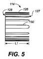
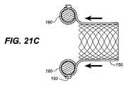
ここで、図5〜図7を参照して、密封スリーブ114をさらに詳細に説明する。前述のように、密封スリーブ114は、移植中に送達系内で拘束された時に、第1の構成に変形されるように構成されている。図5は、略直円筒126が第1の形態である、分岐プロテーゼ100の密封スリーブ114の概略側面図である。円筒126は、第1の端部127と、第2の端部128とを有する。一実施形態では、略直円筒126の第1の変形構成における密封スリーブ114は、1cmから3cmの間の長さL1を有する。図5には示されていないが、第2の端部128は、円筒126が環状フランジ112から近位に延在するように、環状フランジ112と連続する。密封スリーブ114は、第1の端部127にループまたは折り返しを有する、略直線のフィラメント150を含む。略直線のフィラメント150は、図の中では比較的に広く離れて示されているが、該フィラメントは、代替的に、単一ワイヤと見分けられない程度に密に並べて構成することが可能であり、または代替的に、単一ワイヤストランドを使用した密封スリーブとしての役割を果たすように、単一ワイヤを、溶接によって、圧着によって、または本体のフィラメントの単一ワイヤ延長部として、分岐プロテーゼの本体に接続してもよい。 Here, the sealing
図6は、第2の形態に展開し始めた時の密封スリーブ114の概略側面図である。円筒126の第1の端部127は、送達デバイスの拘束から解放された時に、巻き上げられたストッキングまたは靴下と同様に、該第1の端部自体が第2の端部128に向かって巻き上がり始める、またはカールし始める。図6から明らかなように、密封スリーブ114がコイルに巻き上がるにつれて、円筒126の長さが短くなる。図7および図7Aは、完全に展開して、その形状設定を、巻き上げられた、またはコイル状の構成に復元することを可能にした後の、その第2の構成である密封スリーブ114を示す。図7Aは、図7の線A−Aに沿った、密封スリーブ114の断面図である。密封スリーブ114は、展開した時に、環状フランジ112を担持する密に巻回されたコイルに巻き上がる。図7から明らかなように、巻き上げられた密封スリーブ114は、略直円筒126よりも実質的に短い。加えて、巻き上げられた密封スリーブ114は、略直円筒126の第1の変形構成における外径よりも大きい外径を有する。 FIG. 6 is a schematic side view of the sealing
本明細書の一実施形態では、分岐プロテーゼ100は、ニチノール(NiTi)製単一ワイヤ編組から一体的に形成される、一体構造体であってもよい。例えば、図14に示されるように、骨格フレーム101は、単一ワイヤ103から形成される、中空の円筒構造である。管状本体102を形成する編組または網部分は、骨格フレーム101上のほぼ半分に位置し、(図5に関して前述した)フィラメント150は、骨格フレーム101上の残りの半分に位置決めされる。ワイヤ103は、円筒マンドレル(図示せず)に一時的に取り付け、そこに巻き付けて、図14に記載の望ましい編組構成を提供する。単一ワイヤ103の端部は、接合部105で相互に溶接かまたは圧着される。単一ワイヤ103は、略円形の断面であるが、正方形、長方形、D字形状、または任意の他の形状であってもよい。前述のように、骨格フレーム101の少なくとも一部分は、分岐プロテーゼの少なくとも一部分が流体に対して実質的に不透過性であるように、図15に記載の拡大図に示されるように、ポリマーグラフト材料116で被覆されてもよい。一実施形態では、骨格フレーム101の全長は、グラフト材料で覆ってもよく、またはエラストマー含浸、エラストマー膜の積層、ePTFE/PTFE膜の積層によって、不透過性にしてもよい。 In one embodiment herein, the
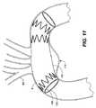
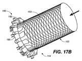
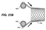
図16〜図21を参照すると、骨格フレーム101から分岐プロテーゼ100を形成するために、骨格フレーム101は、その上に密封アセンブリ110を成形するように、付加的なプロセスのステップと、複数の形状設定サイクルとを受ける。ニチノールは、大部分の金属の数倍である伸び率を有する場合であっても、ニチノールの弾性範囲を超える応力を加えないよう配慮しなければならない。記載される以下のプロセスのステップのそれぞれは、形状設定を実施するために、次のステップとの間に中断を含む(例えば、当技術分野で公知のように、約摂氏500℃の塩浴の中に浸漬する)。より具体的には、図16に示されるように、リング部材180が提供され、該部材は、ポスト182の間にトラフ184を伴うポスト182を含んでもよい。ポスト182は、図16Aに示されるように、フィラメント150の保持を支援するように成形されてもよい。フィラメント150をリング部材180に保持するために、他の類似した手段を使用してもよい。フィラメント150の自由端または非取り付け端の上に挿入されるリング部材180、およびフィラメント150は、図17Aおよび図20Aに示されるように、ポスト182の周囲でループ状にされる。次いで、管状本体102は、図17B〜図17Dおよび図20B〜図20Cに示されるように、リング部材180の中央を通して押し込まれてもよい。この結果、管状本体102がリング部材180の反対側に存在し、フィラメント150がリング部材180の周囲で屈曲することになる。次いで、管状部材102は、図21A〜図21Bに示されるように、拡張されて、リング部材180の上を通過してもよい。この結果、管状本体102がリング部材180に対してその元々の位置に戻り、フィラメント150がもう1度リング部材180の周囲に存在することになる。次いで、管状本体102は、図21Cに矢印によって示されるように、リング部材180の中央を通過して、リング部材180の周囲でフィラメント150をさらに屈曲させてもよい。フィラメント150がリング部材180の周囲で屈曲される回数は、フィラメントにしよされる材料の弾性限度、および密封スリーブに所望される巻き上げ回数に依存する。ロール形成中に材料の弾性限度を超えると、巻き上げられた材料の望ましくない永続的な塑性変形をもたらす。 With reference to FIGS. 16-21, to form the
さらに、密封スリーブ114を形成するプロセスは、リング部材180の外周に配置されたポスト182に関して説明されているが、ポスト(例えば、182)は、代替的に、リング部材の内周上に、またはリング部材180の周囲の他の場所に配置することができる。内周に配置する場合、管状部材102は、リング部材180の左側に動き始めることができ、フィラメント150は、リング部材180の外周に巻き付けて、ポスト上に引っ掛けることができる。これは、フィラメントの180°の屈曲をもたらす。次いで、管状部材102は、リング部材の中央を通過し、それによって、管状部材102がリング部材の反対側に存在し、フィラメント150がさらに180°屈曲する。当業者は、密封スリーブを形成する方法の可能な変形例を認識するであろう。 Further, although the process of forming the sealing
巻き上げ要素およびその対向する肩部を形成するために、各熱処理ステップでは、骨格フレーム101を工具または治具117の中に配置して、熱処理を受けさせる。図18に示される治具117の斜視図を参照すると、治具117は、3つの主要構成要素、すなわち、第1のハウジング118aと、第2のハウジング118bと、成形用マンドレル119とを含む。成形用マンドレル119は、管状コア120と、三角形またはピラミッド状のバンプを外方に形成する、フレア面(拡開面)122を含む。図19に記載の概略側面図を参照すると、リング部材180の周囲で巻き上げられたフィラメント150を有する骨格フレーム101は、成形用マンドレル119の上に配置されて、ハウジング118a、118b内に収容される。治具117内に収容されている間、骨格フレーム101は、熱処理および焼鈍される。熱処理により、骨格フレーム101は、成形用マンドレル119の形状を呈する。より具体的には、成形用マンドレル119のフレア面122は、環状フランジ112を形成し、それによって、プロテーゼ100を展開した時に、フランジ112は、三角形断面を有し、(フレア面122によって形成された)三角形の脚は、分岐プロテーゼ100の外面から半径方向外向きに延在する。加えて、熱処理により、リング部材180は、密封スリーブ114を形成し、それによって、プロテーゼ100が展開した時に、フィラメント150は、巻き上がって、送達デバイスの拘束から展開した時に密に巻回されたコイルとなる。熱処理が完了した時に、フィラメント150は、手で巻き付きを解き、リング部材は、取り外して、これらのような他の分岐プロテーゼのさらなる処理に再使用する。 In each heat treatment step, the
本明細書の別に実施形態では、分岐プロテーゼ100は、相互に取り付けあるいは接続される、別個の、または独立した構成要素から形成されてもよい。より具体的には、管状本体部分102は、後に密封アセンブリ110に取り付けられる、独立した構成要素であってもよい。このように、管状本体部分102は、当業者に公知のあらゆる適切な構成であってもよい。例えば、ステント本体を作製する典型的な方法では、薄肉の小径金属チューブを切断して、レーザー切断または化学エッチング等の方法を使用して、所望のステントパターンを生成する。次いで、切断されたステント本体を、脱スケーリング、研摩、洗浄、およびリンスしてもよい。管状ステント本体を形成する方法のいくつかの例は、Palmazへの米国特許第4,733,665号明細書、Gianturcoへの米国特許第4,800,882号明細書、Wiktorへの米国特許第4,886,062号明細書、Wiktorへの米国特許第5,133,132号明細書、Boneauへの米国特許第5,292,331号明細書、Lauへの米国特許第5,421,955号明細書、Dangへの米国特許第5,935,162号明細書、Globermanへの米国特許第6,090,127号明細書、およびWolinsky他への米国特許第6,130,116号明細書に示され、それぞれ参照することによりその全体が本明細書に組み込まれる。 In other embodiments herein, the
別々に形成される場合、管状本体部分102および密封アセンブリ110は、当技術分野において公知のあらゆる好適な様態で接続または結合されてもよい。例えば、管状本体部分102および密封アセンブリ110は、管状本体部分102および密封アセンブリ110を接続するためにいかなる付加的な材料も使用しないように、抵抗溶接、摩擦溶接、レーザー溶接、または別の溶接形態等によって、相互に溶接してもよい。代替的に、管状本体部分102および密封アセンブリ110は、はんだ付けによって、それらの間に接続要素を追加することによって、または別の機械的方法によって接続することができる。管状本体部分102および密封アセンブリ110を接続するための他の接続または方法は、当業者に明らかであり、本明細書に含まれる。 When formed separately, the
分岐プロテーゼ100は、あらゆる好適な送達系によって送達されてもよい。例えば、図8は、自己拡張型分岐プロテーゼ100を送達して展開するための、例示的な送達系の概略図側面図を示す。送達系は、近位端132および遠位端136を有する引き込み可能な外側軸130と、近位端140および遠位端142を有する内側軸138とを含む。外側軸130は、でそこで延在している管腔(図示せず)を画定し、内側軸138は、外側軸130の管腔を通して送達系の遠位先端部144まで摺動可能に延在する。遠位先端部144は、内側軸138の遠位端142に連結され、狭く蛇行した血管の中での追従性を提供するように、先細で可撓性のあるものであってもよい。ある実施形態では、内側軸138は、そこを通してガイドワイヤ(図示せず)を受け入れるための、ガイドワイヤルーメン(図示せず)を画定してもよい。ガイドワイヤルーメンが存在する場合、内側軸138は、内在するガイドワイヤを越えて、標的部位まで送達系に追従する。代替的に、内側軸138は、代わりに、そこを通って延在する管腔を伴わない、中実ロッド(図示せず)であってもよい。内側軸138が中実ロッドである実施形態では、内側軸138は、先細の遠位先端部144の支援によって標的部位まで追従される。
分岐プロテーゼ100は、密封アセンブリ110が送達系のハブに関して管状本体102よりも近位にあるように、内側軸138の遠位端142に取付けられてもよい。外側軸130は、内側軸138の遠位端142上に取付けられる分岐プロテーゼ100(図8には示さず)を覆う一方で、送達系が体内管腔を通して展開場所まで追従されるように提供される。外側軸130は、内側軸138に沿って、および該内側軸に対して軸方向に移動可能であり、送達系の近位部分まで延在し、そこでハンドル134等のアクチュエータを介して制御して、内側軸138の遠位端142上に取付けられた分岐プロテーゼ100を選択的に拡張させる。引き込められていない位置の外側軸130は、拘束された直径構成の分岐プロテーゼ100を含有する。拘束された形態では、フィラメント150は、リング部材180から巻出されて、直線状にされる。外側軸130は、その展開まで、直線状にされた形態でフィラメント150を拘束する。ハンドル134は、外側軸130の近位端132に連結される、プッシュプルアクチュエータであってもよい。分岐プロテーゼ100を拡張するために、内側軸138の近位端140の固定を保持する一方で、ハンドル134を引っ張り、外側軸130を矢印146の方向に引き込める。代替的に、アクチュエータは、外側軸130の近位端132に連結される回転ノブ(図示せず)であってもよく、それによって、該ノブを回転させた時に、外側軸130は、矢印146の方向に引き込められて分岐プロテーゼ100を拡張させる。したがって、アクチュエータを操作した時に、すなわちこれを手で回した、または引いた時に、外部軸130は、矢印146によって示されるように、内側軸138上を近位方向に引き込められる。図8に示されるように、外側軸130は、引き込められていない送達形態である。完全長の引き込み可能なシースとして説明されているが、外側軸130は、代替的に、比較的に短い、すなわち、分岐プロテーゼ100の長さよりもわずかしか長くないグラフトであってもよい、比較的に短いグラフトカバーは、グラフトカバーとアクチュエータとの間に延在する1つまたは複数の接続要素を介して、前述したプッシュプルハンドルデバイスまたは回転ノブ等の送達デバイスの近位端でアクチュエータに連結されることによって、送達システムのハブに関して近位に引き込み可能である。 The
外側軸130が送達系のハブに関して近位に引き込められると、自己拡張型分岐プロテーゼ100が解放されて、その拡張形態を呈することを可能にする。図8に記載の送達系を、密封アセンブリ110が送達系のハブに関して管状本体102よりも近位にあるように取付けられた分岐プロテーゼ100とともに利用した時に、管状本体102は、外側軸130が矢印146の方向に引き込められるにつれて、最初に展開または露出される。より具体的には、最初に、管状本体102が展開し、続いて、環状フランジ112が展開し、最後に、密封スリーブ114が解放されて、その巻き上げられた、またはコイル状の形態を呈することを可能にする。この様態では、環状フランジ112は、最初に、展開した主プロテーゼの外面に沿って開窓の外辺部を押圧する。次いで、密封スリーブ114は、展開して、展開したフランジ112と並列して、展開した主プロテーゼの内面に沿って、開窓の外辺部に対して巻き上がる。一実施形態では、密封スリーブが、密封スリーブの近位端がフランジに向かって折り返されるように、コイルに巻き上げられている。また、いくつかの実施形態では、密封スリーブの近位端が、フランジに向かってターンするすなわち折り返され密封スリーブの近位端が密封スリーブの近位端より遠位側の部分に接触するように、コイルに巻き上げられている。図8に記載の送達系は、図11〜図13に関して本明細書で説明されるように、分岐プロテーゼ100を、展開した主血管プロテーゼを通して、標的分岐血管に送達する時に有用であり得る。例えば、展開した主血管プロテーゼは、大動脈弓、下行大動脈、または腹部大動脈内に位置してもよく、分岐プロテーゼ100は、大腿動脈の分岐を通して脈管構造の中に導入されてもよい。When the
分岐プロテーゼ100は、当技術分野において公知のあらゆる好適な構成によって、内側軸138の遠位端142に取付けられてもよい。例えば、分岐プロテーゼ100と内側軸との間に延在する取り付け帯は、送達中に分岐プロテーゼ100を適所に保持する手段として作用するように使用されてもよい。取り付け帯は、最終的には、取り付け帯の自己拡張によって分岐プロテーゼ100を解放する。送達中に分岐プロテーゼ100を送達系内の適所に保持するために、他の手段が使用されてもよい。例えば、分岐プロテーゼ100は、分岐プロテーゼ100が経腔的に標的部位まで追従される時に、該分岐プロテーゼの確実な取付けを確保するように、内側軸の外面に形成されるスロット、稜、ポケット、または他のプロテーゼ保持特徴(図示せず)を含めることによって、送達系との摩擦係合を保持してもよい。加えて、分岐プロテーゼ100を半径方向に圧縮された形態に保持するために、キャップを内側軸の遠位端に連結してもよい。送達系の近位部分のアクチュエータは、キャップからの、および半径方向に圧縮された形態からの分岐プロテーゼ100の解放を精密に制御し得る。このような送達系は、Wrightへの米国特許第7,264,632号明細書(参照することによりその全体が本明細書に組み込まれる)に記載される送達系、または当技術分野において公知である他の当該の類似した送達系であってもよい。 The
内側軸130および外側軸138は、あらゆる好適な可撓性ポリマー材料で構成されてもよい。カテーテル軸のための材料の網羅的でない例には、ポリエチレンテレファレート(PET)、ナイロン、ポリエチレン、PEBAX、混紡されるか、または共押し出しされたそれらの組み合わせである。随意に、カテーテル軸の一部分は、強度、柔軟性、および/または靭性を強化するために、ポリマー本体内に強化材料を組み込んだ複合材として構成されてもよい。好適な強化層には、編組み、ワイヤメッシュ層、埋め込み軸ワイヤ、埋め込み螺旋または円周ワイヤ等が挙げられる。ある実施形態では、カテーテル軸の近位部分は、場合によって、例えばFollmer他への米国特許第5,827,242号明細書(参照することによりその全体が本明細書に組み込まれる)に図示および説明されているような、強化ポリマーチューブから構成されてもよい。カテーテル軸は、分岐プロテーゼ100が移植される標的位置まで延在するように、例えば550mmから600mmといった、任意の好適な作業長さを有してもよい。
図9は、自己拡張型分岐プロテーゼ100を送達して展開するための、代替の送達系の概略側面図を示す。送達系は、近位端932および遠位端936を有する比較的に短いグラフトカバー930と、近位端940および遠位端942を有する内側軸938とを含む。前述した実施形態と同様に、内側軸938は、ガイドワイヤルーメン(図示せず)を画定しても、しなくてもよく、また、狭く蛇行した血管の中での追従性を提供するように、遠位端942に連結された、先細で可撓性のある遠位先端部944を含んでもよい。分岐プロテーゼ100は、密封アセンブリ110が送達系のハブに関して管状本体102よりも遠位にあるように、内側軸938の遠位端942に取付けられてもよい。分岐プロテーゼ100は、図8に関して前述したもの等の、当技術分野において公知のあらゆる好適な構成によって取付けられてもよい。 FIG. 9 shows a schematic side view of an alternative delivery system for delivering and deploying a self-expanding
グラフトカバー930は、内側軸938の遠位端942上に取付けられる分岐プロテーゼ100(図9には示さず)を覆って拘束する一方で、送達系が体内管腔を通して展開場所まで追従されるように提供される。グラフトカバー930は、比較的に短い、すなわち、分岐プロテーゼ100の長さよりもわずかしか長くない。グラフトカバー930は、プッシャーロッド941に取り付けられるが、該プッシャーロッドは、その近位端が内側軸938の近位端940の外に出るように、内側軸938の管腔(図示せず)の中に延在する。プッシャーロッド941は、内側軸938内で、および該内側軸に対して軸方向に移動可能であり、分岐プロテーゼ100を選択的に拡張するように、操作者によって操作されてもよい。分岐プロテーゼ100を拡張するために、内側軸938の近位端940の固定を保持する一方で、分岐プロテーゼ100を除覆または露出するために、矢印947によって示されるように、プッシャーロッド941(および取り付けられたグラフトカバー930)を遠位に進行させる。分岐プロテーゼ100が完全に除覆されて展開すると、送達系は、分岐プロテーゼ100の拡張した管腔の中に引き込められ、患者から取り外される。図9には示されていないが、プッシャーロッド941の近位端は、図8に関して前述したようなプッシュプルハンドルデバイスまたは回転ノブ等の、分岐プロテーゼ100を拡張するためのアクチュエータに連結されてもよいことを理解されたい。
グラフトカバー930が送達系のハブに関して遠位に進行させられると、自己拡張型分岐プロテーゼ100が解放されて、その拡張形態を呈することを可能にする。図9に記載の送達系を、密封アセンブリ110が送達系のハブに関して管状本体102より遠位にあるように取付けられた分岐プロテーゼ100とともに利用することで、管状本体102は、グラフトカバー930が矢印947の方向にプッシャーロッド941を介して進行するにつれて、最初に展開または露出される。より具体的には、最初に、管状本体102が展開し、続いて、環状フランジ112が展開し、最後に、密封スリーブ114が解放されて、展開したフランジ112と並置に、その巻き上げられた、またはコイル状の形態を呈することを可能にする。図9に記載の送達系は、分岐プロテーゼ100を、標的側枝血管を通して、標的分岐血管に送達する時に有用であり得る。例えば、分岐プロテーゼ100は、標的分岐血管を通して送達するために、補助動脈を介して、頸動脈を通して脈管構造の中に導入されてもよい。 As the
前述のように、分岐プロテーゼ100は、側開口部を有する主血管プロテーゼとともに使用するために構成され、主血管の中で展開する。例示的な主プロテーゼを図10に示す。主プロテーゼ160は、管状本体172として成形される、合成グラフト材料を含む。主プロテーゼ160は、環状支持部材、またはその端部を支持するためにそれに取り付けられる、ステント162を含む。図10は、グラフト材料に取り付けられる、3つのステント162を示すが、より多い、またはより少ない数のステントを利用してもよい。ステント162は、あらゆる好適な構成を有してもよい。このような環状支持構造体の例は、例えば、米国特許第5,713,917号明細書および米国特許第5,824,041号明細書に記載されており、これらは参照することによりその全体が本明細書に組み込まれる。動脈瘤除外デバイスで使用される時に、ステントは、プロテーゼを体内管腔の内壁と合致して係合するように、過度の漏出を回避するように、および動脈瘤の加圧を防止する、すなわち、漏れ耐性のある密封を提供するように、十分な半径方向のばね力および柔軟性を有する。グラフトプロテーゼによって隔離された動脈瘤の中への血液または他の体液のいくらかの漏出が生じるかもしれないが、最適な密封は、動脈瘤の加圧および結果として生じる破裂の可能性を低減する。ステント162は、好ましくは、シースなどの抑制機構からの解放によって展開する、自己拡張型ばね部材である。例えば、ステント162は、ニチノール等の超弾性材料で構成されてもよい。示される実施形態では、主プロテーゼ160の中間部分は、その長さに沿っていかなる半径方向の支持もない、単なるグラフト材料であり、すなわち、ステントがなく、支持されていない。支持されていない本体部分は、可撓性があり、大動脈弓等の非常に湾曲した解剖学的構造の中にプロテーゼを配置することを可能にする。しかしながら、支持されていない本体部分の存在および長さは、所望のアプリケーションに応じて変動する。 As described above, the
主プロテーゼ160は、外辺部166を有する開窓または開口部164を、主プロテーゼ160の側壁に含む。開窓164は、主プロテーゼ160の内面168から主プロテーゼ160の外面170まで延在し、血液が側枝血管の中に流れることを可能にするために使用される。図10に示されるように、開窓164は、主プロテーゼ160を患者に挿入する前に、該主プロテーゼ上に予備成形されていてもよい。代替的に、開窓164は、図10に関して以下にさらに詳細に説明するように、主プロテーゼ160が標的血管の中で展開した後で、現場で形成されてもよい。 The
ここで、図11〜図13を参照すると、本明細書の実施形態による、主プロテーゼと分岐プロテーゼとの間に流体密封を形成するための方法が記載される。図11は、大動脈(図11〜図13においてAで示す)内で展開した、より具体的には大動脈弓内で展開した主プロテーゼ160の側面図である。大動脈弓は、複数の側枝血管を有し、その血管には、左鎖骨下動脈、左総頸動脈、ならびに右鎖骨下動脈および右総頸動脈にさらに分岐する腕頭動脈が挙げられる。以下の、主プロテーゼと分岐プロテーゼとの間に流体密封を形成する方法は、腕頭動脈(図11〜図13においてBVで示す)に潅流を提供するように説明されているが、本方法は、左鎖骨下動脈または左総頸動脈、ならびに大動脈弓以外の他の血管の側枝血管に潅流を提供するために利用されてもよいことを理解されるであろう。例えば、本方法は、腎動脈等の腹部大動脈から側枝血管に潅流を提供するために利用されてもよい。 Referring now to FIGS. 11-13, a method for forming a fluid seal between a main prosthesis and a branch prosthesis according to embodiments herein will be described. FIG. 11 is a side view of the
さらに図11を参照すると、展開した主プロテーゼ160は、動脈瘤174に架かる。主プロテーゼ160が予め開窓のあるグラフトグラフトである場合、主プロテーゼ160は、開窓164(図11では不可視)が分岐血管BVの小孔と整合するように、大動脈A内に位置決めされる。代替的に、開窓164は、分岐血管BVに潅流させるように、現場で作成されてもよい。開窓164を作製するために、主プロテーゼ160のグラフト材料を通して穿刺するのに十分な尖った先端部を有する拡張器および針の組み合わせデバイス等の、別個の穿刺デバイスが送達されてもよい。本構造の実施形態は、主プロテーゼ160に開窓を作成することが可能な、あらゆる従来の穿刺デバイスとともに使用されてもよい。例えば、穿刺デバイスは、例えば生検針、RFドーム電極、またはRF環状電極といった当技術分野において公知の穿刺デバイスであってもよく、2008年3月6日に出願されたBruszewski他の米国特許出願第11/939106号明細書(参照することによりその全体が本明細書に組み込まれる)に図示または説明されるものが挙げられるが、これに限定されない。 Still referring to FIG. 11, the deployed
ここで、図12を参照すると、送達系を携持する分岐プロテーゼ100が、標的分岐血管BVに送達されるように示される。例えば、図8に関して前述したように、送達系は、分岐プロテーゼ100を送達するために利用されてもよい。送達系、およびしたがって、分岐プロテーゼ100は、大腿動脈の分岐を通して脈管構造の中に導入され、展開した主プロテーゼ160を通して分岐血管BVに送達されてもよい。送達系は、展開した主プロテーゼ160を通して、開窓164(図12では不可視)を介して分岐血管BVの中に延在する。引き込み可能な軸130は、分岐プロテーゼ100を圧縮形態に抑制し、該分岐プロテーゼが、動脈瘤場所に送達される時に、管腔壁を損傷する、またはそこに引っかかることを防止する。血管内にグラフトを送達するための手術方法および装置は、一般的に、当技術分野において公知であり、グラフト送達系を脈管構造内に配置して、グラフトを展開場所に送達するために使用されてもよい。例えば、グラフトは、蛍光透視鏡撮像を使用する展開場所に誘導されてもよい。当業者は、分岐プロテーゼ100が、代替的に、補助動脈を介して頸動脈を通して脈管構造の中に送達されて、図9に関して前述した送達系によって分岐血管BVを通して送達されてもよいことを理解されたい。 Referring now to FIG. 12, a
分岐血管プロテーゼ100が所望に応じて分岐血管BV内に位置決めされると、外側軸130は、送達系のハブに関して近位方向に引き込められて、分岐プロテーゼ100が血管壁と並置する状態に自己拡張すること可能にする。外軸130が引き込められるにつれて、最初に、管状本体102が分岐血管BV内で展開し、続いて、環状フランジ112が展開し、最後に、密封スリーブ114が解放されて、その巻き上げられた、またはコイル状の形態を呈することを可能にする。この様態では、環状フランジ112は、最初に、展開した主プロテーゼ160の外面170に沿って開窓164の外辺部166を押圧する。次いで、密封スリーブ114は、展開して、展開したフランジ112と並置に、展開した主プロテーゼ160の内面168に沿って、開窓164の外辺部166に対して巻き上がる。密封スリーブ114は、主プロテーゼ160の布または材料を捕捉し、それを環状フランジ112に押圧して、主プロテーゼ160と分岐プロテーゼ100との間に流体密封を形成する(図4も参照)。分岐プロテーゼ100は、主プロテーゼ160の開窓164を通って流れる血液を、分岐血管BVの管腔に方向付ける管路として機能する。図13に示されるように、分岐プロテーゼ100は、その展開または拡張した形態であり、送達系は、患者から取り外される。 When the
本発明による種々の実施形態を上記に説明してきたが、それらは、説明および例示だけのために提示されたものであり、限定するものではないことを理解されたい。本発明の精神および範囲から逸脱することなく、形態および細部の種々の変更を行うことができることが、当業者には明白となるであろう。したがって、本発明の広さおよび範囲は、前述の例示的な実施形態のいずれかに限定されるものではなく、以下の請求項およびそれらの同等物によってのみ定義されるべきである。また、本明細書で論じられる各実施形態、および本明細書に引用される各参考文献の各特徴は、任意の他の実施形態の特徴と組み合わせて使用できることを理解されるであろう。本明細書で論じられる全ての特許および刊行物は、参照することによりその全体が本明細書に組み込まれる。 While various embodiments in accordance with the present invention have been described above, it should be understood that they have been presented for purposes of illustration and illustration only and not limitation. It will be apparent to those skilled in the art that various modifications can be made in form and detail without departing from the spirit and scope of the invention. Accordingly, the breadth and scope of the present invention should not be limited to any of the above-described exemplary embodiments, but should be defined only in accordance with the following claims and their equivalents. It will also be understood that each embodiment discussed herein and each feature of each reference cited herein can be used in combination with the features of any other embodiment. All patents and publications discussed herein are hereby incorporated by reference in their entirety.
Claims (15)
Translated fromJapanese主血管の中に配置されるように構成され、外面と、内面と、外辺部を含む側部開口とを有する主補綴具と、
前記主血管から延びる分枝血管の中に配置されるように構成された分枝補綴具であって、径方向の圧縮された第1形態と径方向に拡張した第2形態とを有する分枝補綴具とを備え、
該分枝補綴具が、
前記第2形態で第1の外径を有し、近位端および遠位端を有する拡張可能な管状本体部分と、
前記本体部分の前記近位端に連結され、前記第2形態で前記第1の外径よりも大きい第2の外径を有する拡張可能な環状フランジと、
前記拡張可能なフランジから近位方向に延び、前記第1の形態では略真直ぐな円筒中空形状であり、前記第2の形態では巻上げられて前記環状フランジに当接するコイルになるシールスリーブと、を備え、
前記第2の形態では、前記環状フランジが、前記側部開口の前記外辺部の周囲で前記主補綴具の前記外面に係合し、前記シールスリープが前記側部開口の前記外辺部の周囲で前記主補綴具の前記内面に係合し、前記主補綴具と分枝補綴具との間でシールを形成する、
ことを特徴とする主補綴具と側枝用補綴具の組立体。An assembly of a main prosthesis and a branch prosthesis,
A main prosthesis configured to be disposed within the main blood vessel and having an outer surface, an inner surface, and a side opening including an outer edge;
A branch prosthesis configured to be placed in a branch vessel extending from the main vessel, the branch having a radially compressed first configuration and a radially expanded second configuration With a prosthesis,
The branch prosthesis is
An expandable tubular body portion having a first outer diameter in the second configuration and having a proximal end and a distal end;
An expandable annular flange coupled to the proximal end of the body portion and having a second outer diameter that is greater than the first outer diameter in the second configuration;
A seal sleeve extending proximally from the expandable flange and having a generally straight cylindrical hollow shape in the first configuration and beingcoiled in the second configurationto be coiled against the annular flange. Prepared,
In the second form, the annular flange engages with the outer surface of the main prosthesis around the outer edge of theside opening, and the seal sleep of the outer edge of the side opening. Engaging the inner surface of the main prosthesis at a periphery to form a seal between the main prosthesis and the branch prosthesis;
An assembly of a main prosthesis and a side branch prosthesis.
請求項1に記載の組立体。The body portion is an expandable Nitinol (NiTi) single wire braid,
The assembly according to claim 1.
請求項2に記載の組立体。The body portion is impervious due to elastomer impregnation, elastomer membrane lamination, or ePTFE membrane lamination,
The assembly according to claim 2.
請求項1に記載の組立体。The body portion and the flange are a single wire braid made of expandable integral Nitinol (NiTi),
The assembly according to claim 1.
請求項4に記載の組立体。The single wire has a straight portion extending from the flange to the seal sleeve and having a loop at the proximal end;
The assembly according to claim 4.
請求項1に記載の組立体。The flange and the seal sleeve are integrally formed and attached to the body portion;
The assembly according to claim 1.
請求項1に記載の組立体。The body portion, flange, and seal sleeve are formed from an expandable Nitinol (NiTi) single wire braid that is impervious by elastomer impregnation, elastomer membrane lamination, or ePTFE membrane lamination. ,
The assembly according to claim 1.
請求項1に記載の組立体。The body portion has a length between 40 mm and 60 mm;
The assembly according to claim 1.
請求項1に記載の組立体。The seal sleeve has a length between 1 cm and 3 cm in the first configuration;
The assembly according to claim 1.
請求項1に記載の組立体。The first outer diameter of the body portion is between 5 mm and 8 mm;
The assembly according to claim 1.
請求項1に記載の組立体。The first outer diameter of the body portion is between 8 mm and 14 mm;
The assembly according to claim 1.
請求項1に記載の組立体。The flange has a triangular cross-section;
The assembly according to claim 1.
請求項1に記載の組立体。The body portion includes a graft material;
The assembly according to claim 1.
請求項14に記載の組立体。The graft material is selected from the group consisting of woven polyester, expanded polytetrafluoroethylene, Dacron, polyurethane, and silicone;
The assembly according to claim 14.
Applications Claiming Priority (3)
| Application Number | Priority Date | Filing Date | Title |
|---|---|---|---|
| US12/409,012 | 2009-03-23 | ||
| US12/409,012US8052741B2 (en) | 2009-03-23 | 2009-03-23 | Branch vessel prosthesis with a roll-up sealing assembly |
| PCT/US2010/026267WO2010111011A1 (en) | 2009-03-23 | 2010-03-04 | Branch vessel prosthesis with a roll-up sealing assembly |
Publications (3)
| Publication Number | Publication Date |
|---|---|
| JP2012521267A JP2012521267A (en) | 2012-09-13 |
| JP2012521267A5 JP2012521267A5 (en) | 2013-04-18 |
| JP5643806B2true JP5643806B2 (en) | 2014-12-17 |
Family
ID=42154572
Family Applications (1)
| Application Number | Title | Priority Date | Filing Date |
|---|---|---|---|
| JP2012502081AExpired - Fee RelatedJP5643806B2 (en) | 2009-03-23 | 2010-03-04 | Branch vessel prosthesis with roll-up seal assembly |
Country Status (5)
| Country | Link |
|---|---|
| US (1) | US8052741B2 (en) |
| EP (1) | EP2410944B1 (en) |
| JP (1) | JP5643806B2 (en) |
| CN (1) | CN102368974B (en) |
| WO (1) | WO2010111011A1 (en) |
Families Citing this family (118)
| Publication number | Priority date | Publication date | Assignee | Title |
|---|---|---|---|---|
| US20120089220A1 (en)* | 2000-02-18 | 2012-04-12 | E.V.R. Endovascular Researches S.A. | Microcatheter |
| US7147661B2 (en) | 2001-12-20 | 2006-12-12 | Boston Scientific Santa Rosa Corp. | Radially expandable stent |
| ES2624595T3 (en) | 2007-03-05 | 2017-07-17 | Endospan Ltd | Bifurcated, supportive, expandable endoluminal grafts with multiple components and methods for use |
| EP2173259A4 (en) | 2007-08-02 | 2015-07-08 | Bio Connect Systems | Implantable flow connector |
| US20130197546A1 (en) | 2007-08-02 | 2013-08-01 | Bioconnect Systems, Inc. | Implantable flow connector |
| EP3443938B1 (en) | 2007-09-26 | 2024-01-24 | St. Jude Medical, LLC | Collapsible prosthetic heart valves |
| US9532868B2 (en) | 2007-09-28 | 2017-01-03 | St. Jude Medical, Inc. | Collapsible-expandable prosthetic heart valves with structures for clamping native tissue |
| US8454632B2 (en) | 2008-05-12 | 2013-06-04 | Xlumena, Inc. | Tissue anchor for securing tissue layers |
| US20090281379A1 (en) | 2008-05-12 | 2009-11-12 | Xlumena, Inc. | System and method for transluminal access |
| EP2815724B2 (en) | 2008-07-15 | 2024-03-13 | St. Jude Medical, Inc. | Collapsible and re-expandable prosthetic heart valve cuff designs and complementary technological applications |
| AU2010218384B2 (en) | 2009-02-27 | 2014-11-20 | St. Jude Medical, Inc. | Stent features for collapsible prosthetic heart valves |
| JP5535313B2 (en) | 2009-05-29 | 2014-07-02 | エックスルミナ, インコーポレイテッド | Device and method for deploying a stent across adjacent tissue layers |
| CA3009244C (en) | 2009-06-23 | 2020-04-28 | Endospan Ltd. | Vascular prostheses for treating aneurysms |
| WO2011007354A1 (en)* | 2009-07-14 | 2011-01-20 | Endospan Ltd. | Sideport engagement and sealing mechanism for endoluminal stent-grafts |
| CN102740807B (en) | 2009-11-30 | 2015-11-25 | 恩多斯潘有限公司 | Multi-component stent-graft system for implantation into vessels with multiple branches |
| US8870950B2 (en) | 2009-12-08 | 2014-10-28 | Mitral Tech Ltd. | Rotation-based anchoring of an implant |
| US9468517B2 (en) | 2010-02-08 | 2016-10-18 | Endospan Ltd. | Thermal energy application for prevention and management of endoleaks in stent-grafts |
| US20110224785A1 (en) | 2010-03-10 | 2011-09-15 | Hacohen Gil | Prosthetic mitral valve with tissue anchors |
| US9132009B2 (en) | 2010-07-21 | 2015-09-15 | Mitraltech Ltd. | Guide wires with commissural anchors to advance a prosthetic valve |
| US9763657B2 (en) | 2010-07-21 | 2017-09-19 | Mitraltech Ltd. | Techniques for percutaneous mitral valve replacement and sealing |
| US11653910B2 (en) | 2010-07-21 | 2023-05-23 | Cardiovalve Ltd. | Helical anchor implantation |
| US8992604B2 (en) | 2010-07-21 | 2015-03-31 | Mitraltech Ltd. | Techniques for percutaneous mitral valve replacement and sealing |
| WO2012018917A1 (en)* | 2010-08-03 | 2012-02-09 | World Heart Corporation | Conformal cannula device and related methods |
| CA2826022A1 (en) | 2011-02-03 | 2012-08-09 | Endospan Ltd. | Implantable medical devices constructed of shape memory material |
| WO2012117395A1 (en) | 2011-03-02 | 2012-09-07 | Endospan Ltd. | Reduced-strain extra- vascular ring for treating aortic aneurysm |
| EP2720626B1 (en)* | 2011-06-15 | 2017-06-14 | Phraxis Inc. | Anastomotic connector and system for delivery |
| JP5866131B2 (en) | 2011-06-15 | 2016-02-17 | フラクシス インコーポレイテッド | Anastomotic connector |
| US9254209B2 (en) | 2011-07-07 | 2016-02-09 | Endospan Ltd. | Stent fixation with reduced plastic deformation |
| US20140324164A1 (en) | 2011-08-05 | 2014-10-30 | Mitraltech Ltd. | Techniques for percutaneous mitral valve replacement and sealing |
| US8852272B2 (en) | 2011-08-05 | 2014-10-07 | Mitraltech Ltd. | Techniques for percutaneous mitral valve replacement and sealing |
| EP2739214B1 (en) | 2011-08-05 | 2018-10-10 | Cardiovalve Ltd | Percutaneous mitral valve replacement and sealing |
| WO2013021374A2 (en) | 2011-08-05 | 2013-02-14 | Mitraltech Ltd. | Techniques for percutaneous mitral valve replacement and sealing |
| US9839510B2 (en) | 2011-08-28 | 2017-12-12 | Endospan Ltd. | Stent-grafts with post-deployment variable radial displacement |
| EP2751323B1 (en) | 2011-09-01 | 2020-03-25 | Cook Medical Technologies LLC | Method of forming a braided helical wire stent |
| US9427339B2 (en) | 2011-10-30 | 2016-08-30 | Endospan Ltd. | Triple-collar stent-graft |
| US20140350669A1 (en)* | 2011-12-01 | 2014-11-27 | The Trustees if The University of Pennsylvania | Percutaneous valve replacement devices |
| US9597204B2 (en) | 2011-12-04 | 2017-03-21 | Endospan Ltd. | Branched stent-graft system |
| FR2984112B1 (en)* | 2011-12-15 | 2013-12-06 | Assist Publ Hopitaux De Paris | ENDOVASCULAR PROSTHESIS |
| US9314600B2 (en) | 2012-04-15 | 2016-04-19 | Bioconnect Systems, Inc. | Delivery system for implantable flow connector |
| US10434293B2 (en) | 2012-04-15 | 2019-10-08 | Tva Medical, Inc. | Implantable flow connector |
| WO2013171730A1 (en) | 2012-05-15 | 2013-11-21 | Endospan Ltd. | Stent-graft with fixation elements that are radially confined for delivery |
| JP6360042B2 (en) | 2012-05-17 | 2018-07-18 | ボストン サイエンティフィック サイムド,インコーポレイテッドBoston Scientific Scimed,Inc. | Method and device for access across adjacent tissue layers |
| EP2861182B1 (en) | 2012-06-15 | 2019-02-20 | Phraxis Inc. | Arterial and venous anchor devices forming an anastomotic connector |
| US9993360B2 (en) | 2013-01-08 | 2018-06-12 | Endospan Ltd. | Minimization of stent-graft migration during implantation |
| US20150351906A1 (en) | 2013-01-24 | 2015-12-10 | Mitraltech Ltd. | Ventricularly-anchored prosthetic valves |
| ES2980140T3 (en)* | 2013-02-21 | 2024-09-30 | Boston Scient Scimed Inc | Devices for forming an anastomosis |
| US9668892B2 (en) | 2013-03-11 | 2017-06-06 | Endospan Ltd. | Multi-component stent-graft system for aortic dissections |
| US9398951B2 (en) | 2013-03-12 | 2016-07-26 | St. Jude Medical, Cardiology Division, Inc. | Self-actuating sealing portions for paravalvular leak protection |
| US10271949B2 (en) | 2013-03-12 | 2019-04-30 | St. Jude Medical, Cardiology Division, Inc. | Paravalvular leak occlusion device for self-expanding heart valves |
| US9339274B2 (en) | 2013-03-12 | 2016-05-17 | St. Jude Medical, Cardiology Division, Inc. | Paravalvular leak occlusion device for self-expanding heart valves |
| EP2967849B1 (en) | 2013-03-12 | 2025-08-13 | St. Jude Medical, Cardiology Division, Inc. | Self-actuating sealing portions for paravalvular leak protection |
| US8986375B2 (en)* | 2013-03-12 | 2015-03-24 | Medtronic, Inc. | Anti-paravalvular leakage component for a transcatheter valve prosthesis |
| US10561509B2 (en) | 2013-03-13 | 2020-02-18 | DePuy Synthes Products, Inc. | Braided stent with expansion ring and method of delivery |
| US9326856B2 (en) | 2013-03-14 | 2016-05-03 | St. Jude Medical, Cardiology Division, Inc. | Cuff configurations for prosthetic heart valve |
| WO2014204807A1 (en) | 2013-06-19 | 2014-12-24 | Aga Medical Corporation | Collapsible valve having paravalvular leak protection |
| US10117742B2 (en) | 2013-09-12 | 2018-11-06 | St. Jude Medical, Cardiology Division, Inc. | Stent designs for prosthetic heart valves |
| US9913715B2 (en) | 2013-11-06 | 2018-03-13 | St. Jude Medical, Cardiology Division, Inc. | Paravalvular leak sealing mechanism |
| EP4176844B1 (en) | 2013-11-06 | 2025-08-20 | St. Jude Medical, Cardiology Division, Inc. | Reduced profile prosthetic heart valve |
| EP2870946B1 (en) | 2013-11-06 | 2018-10-31 | St. Jude Medical, Cardiology Division, Inc. | Paravalvular leak sealing mechanism |
| WO2015075708A1 (en) | 2013-11-19 | 2015-05-28 | Endospan Ltd. | Stent system with radial-expansion locking |
| WO2015077274A1 (en) | 2013-11-19 | 2015-05-28 | St. Jude Medical, Cardiology Division, Inc. | Sealing structures for paravalvular leak protection |
| US9820852B2 (en) | 2014-01-24 | 2017-11-21 | St. Jude Medical, Cardiology Division, Inc. | Stationary intra-annular halo designs for paravalvular leak (PVL) reduction—active channel filling cuff designs |
| US20150209141A1 (en) | 2014-01-24 | 2015-07-30 | St. Jude Medical, Cardiology Division, Inc. | Stationary intra-annular halo designs for paravalvular leak (pvl) reduction-passive channel filling cuff designs |
| WO2015126712A1 (en) | 2014-02-18 | 2015-08-27 | St. Jude Medical, Cardiology Division, Inc. | Bowed runners for paravalvular leak protection |
| EP3122289A1 (en) | 2014-03-26 | 2017-02-01 | St. Jude Medical, Cardiology Division, Inc. | Transcatheter mitral valve stent frames |
| WO2015152980A1 (en) | 2014-03-31 | 2015-10-08 | St. Jude Medical, Cardiology Division, Inc. | Paravalvular sealing via extended cuff mechanisms |
| US9757230B2 (en) | 2014-05-16 | 2017-09-12 | St. Jude Medical, Cardiology Division, Inc. | Stent assembly for use in prosthetic heart valves |
| ES2795358T3 (en) | 2014-05-16 | 2020-11-23 | St Jude Medical Cardiology Div Inc | Subannular sealing for paravalvular leak protection |
| EP3142604B1 (en) | 2014-05-16 | 2024-01-10 | St. Jude Medical, Cardiology Division, Inc. | Transcatheter valve with paravalvular leak sealing ring |
| CN104116577B (en)* | 2014-06-27 | 2017-07-14 | 先健科技(深圳)有限公司 | Branch type overlay film frame |
| EP3174502B1 (en) | 2014-07-30 | 2022-04-06 | Cardiovalve Ltd | Apparatus for implantation of an articulatable prosthetic valve |
| CN106029005B (en) | 2014-12-18 | 2018-01-19 | 恩都思潘有限公司 | The Endovascular stent-graft of horizontal conduit with tired resistance |
| US9974651B2 (en) | 2015-02-05 | 2018-05-22 | Mitral Tech Ltd. | Prosthetic valve with axially-sliding frames |
| CN110141399B (en) | 2015-02-05 | 2021-07-27 | 卡迪尔维尔福股份有限公司 | Prosthetic valve with axial sliding frame |
| US9962260B2 (en) | 2015-03-24 | 2018-05-08 | St. Jude Medical, Cardiology Division, Inc. | Prosthetic mitral valve |
| KR101691118B1 (en)* | 2015-07-06 | 2016-12-29 | 주식회사 비씨엠 | The resistance of the end-enhanced method for manufacturing a medical stent and a stent |
| KR101691121B1 (en)* | 2015-07-16 | 2016-12-29 | 주식회사 비씨엠 | The tubular stent expansion with enhanced resistance to end |
| DE102016101273A1 (en)* | 2016-01-25 | 2017-07-27 | Christian-Albrechts-Universität Zu Kiel | Stent graft system and a method for coupling stent graft as a stent-graft system |
| US10531866B2 (en) | 2016-02-16 | 2020-01-14 | Cardiovalve Ltd. | Techniques for providing a replacement valve and transseptal communication |
| CN109257925A (en)* | 2016-03-17 | 2019-01-22 | 医药连接技术-医连技术-M.C.T.有限公司 | Medicine connector apparatus |
| EP3903732B1 (en)* | 2016-06-13 | 2025-07-30 | Bolton Medical, Inc. | Devices for reinforcing fenestrations in prosthetic implants |
| US20190231525A1 (en) | 2016-08-01 | 2019-08-01 | Mitraltech Ltd. | Minimally-invasive delivery systems |
| AU2017306141A1 (en)* | 2016-08-02 | 2019-03-07 | Aortica Corporation | Systems, devices, and methods for coupling a prosthetic implant to a fenestrated body |
| USD800908S1 (en) | 2016-08-10 | 2017-10-24 | Mitraltech Ltd. | Prosthetic valve element |
| CA3031187A1 (en) | 2016-08-10 | 2018-02-15 | Cardiovalve Ltd. | Prosthetic valve with concentric frames |
| US10548722B2 (en) | 2016-08-26 | 2020-02-04 | St. Jude Medical, Cardiology Division, Inc. | Prosthetic heart valve with paravalvular leak mitigation features |
| US10456249B2 (en) | 2016-09-15 | 2019-10-29 | St. Jude Medical, Cardiology Division, Inc. | Prosthetic heart valve with paravalvular leak mitigation features |
| US10292851B2 (en) | 2016-09-30 | 2019-05-21 | DePuy Synthes Products, Inc. | Self-expanding device delivery apparatus with dual function bump |
| EP3531977B1 (en) | 2016-10-28 | 2024-06-26 | St. Jude Medical, Cardiology Division, Inc. | Prosthetic mitral valve |
| EP3556326A4 (en) | 2016-12-15 | 2020-07-08 | BCM Co., Ltd. | Method for fabricating medical stent having resistance-reinforced end parts, and stent fabricated thereby |
| US11583383B2 (en)* | 2016-12-28 | 2023-02-21 | Lifetech Scientific (Shenzhen) Co. Ltd. | Luminal stent |
| USD875935S1 (en) | 2017-05-15 | 2020-02-18 | St. Jude Medical, Cardiology Division, Inc. | Stent having tapered struts |
| USD889653S1 (en) | 2017-05-15 | 2020-07-07 | St. Jude Medical, Cardiology Division, Inc. | Stent having tapered struts |
| USD875250S1 (en) | 2017-05-15 | 2020-02-11 | St. Jude Medical, Cardiology Division, Inc. | Stent having tapered aortic struts |
| US10575948B2 (en) | 2017-08-03 | 2020-03-03 | Cardiovalve Ltd. | Prosthetic heart valve |
| US10888421B2 (en) | 2017-09-19 | 2021-01-12 | Cardiovalve Ltd. | Prosthetic heart valve with pouch |
| US11246704B2 (en) | 2017-08-03 | 2022-02-15 | Cardiovalve Ltd. | Prosthetic heart valve |
| US11793633B2 (en) | 2017-08-03 | 2023-10-24 | Cardiovalve Ltd. | Prosthetic heart valve |
| US12064347B2 (en) | 2017-08-03 | 2024-08-20 | Cardiovalve Ltd. | Prosthetic heart valve |
| US10537426B2 (en) | 2017-08-03 | 2020-01-21 | Cardiovalve Ltd. | Prosthetic heart valve |
| JP7249332B2 (en)* | 2017-09-01 | 2023-03-30 | トランスミューラル システムズ エルエルシー | Percutaneous shunt device and related methods |
| JP7271510B2 (en) | 2017-09-25 | 2023-05-11 | ボルトン メディカル インコーポレイテッド | Systems, devices and methods for coupling prosthetic implants to fenestrated bodies |
| US11382751B2 (en) | 2017-10-24 | 2022-07-12 | St. Jude Medical, Cardiology Division, Inc. | Self-expandable filler for mitigating paravalvular leak |
| JP2021013405A (en)* | 2017-11-22 | 2021-02-12 | 川澄化学工業株式会社 | Intravascular indwelling device connection structure and intravascular indwelling system |
| FR3074040B1 (en)* | 2017-11-27 | 2022-03-04 | Id Nest Medical | OPTIMIZED STRUCTURE FOR AN EXPANDABLE IMPLANT OF THE STENT OR ENDOPROSTHESIS TYPE |
| GB201720803D0 (en) | 2017-12-13 | 2018-01-24 | Mitraltech Ltd | Prosthetic Valve and delivery tool therefor |
| GB201800399D0 (en) | 2018-01-10 | 2018-02-21 | Mitraltech Ltd | Temperature-control during crimping of an implant |
| US11813413B2 (en) | 2018-03-27 | 2023-11-14 | St. Jude Medical, Cardiology Division, Inc. | Radiopaque outer cuff for transcatheter valve |
| AU2019204522A1 (en)* | 2018-07-30 | 2020-02-13 | DePuy Synthes Products, Inc. | Systems and methods of manufacturing and using an expansion ring |
| US10456280B1 (en) | 2018-08-06 | 2019-10-29 | DePuy Synthes Products, Inc. | Systems and methods of using a braided implant |
| WO2020060828A1 (en) | 2018-09-20 | 2020-03-26 | St. Jude Medical, Cardiology Division, Inc. | Attachment of leaflets to prosthetic heart valve |
| US11364117B2 (en) | 2018-10-15 | 2022-06-21 | St. Jude Medical, Cardiology Division, Inc. | Braid connections for prosthetic heart valves |
| JP7048096B2 (en)* | 2018-11-14 | 2022-04-05 | 株式会社日本医療機器開発機構 | Stent graft with fenestration part |
| US11471277B2 (en) | 2018-12-10 | 2022-10-18 | St. Jude Medical, Cardiology Division, Inc. | Prosthetic tricuspid valve replacement design |
| EP3902503B1 (en) | 2018-12-26 | 2025-01-29 | St. Jude Medical, Cardiology Division, Inc. | Elevated outer cuff for reducing paravalvular leakage and increasing stent fatigue life |
| FI3941392T3 (en) | 2019-03-20 | 2025-07-28 | Inqb8 Medical Tech Llc | Aortic dissection implant |
| US12357459B2 (en) | 2020-12-03 | 2025-07-15 | Cardiovalve Ltd. | Transluminal delivery system |
| CN116867463A (en)* | 2020-12-29 | 2023-10-10 | 波士顿科学国际有限公司 | Drainage device and use method |
Family Cites Families (107)
| Publication number | Priority date | Publication date | Assignee | Title |
|---|---|---|---|---|
| US4019A (en)* | 1845-05-01 | Pianoforte | ||
| US4733664A (en)* | 1983-12-01 | 1988-03-29 | University Of New Mexico | Surgical clip, applier, and method |
| US4733665C2 (en) | 1985-11-07 | 2002-01-29 | Expandable Grafts Partnership | Expandable intraluminal graft and method and apparatus for implanting an expandable intraluminal graft |
| US4800882A (en) | 1987-03-13 | 1989-01-31 | Cook Incorporated | Endovascular stent and delivery system |
| US4886062A (en) | 1987-10-19 | 1989-12-12 | Medtronic, Inc. | Intravascular radially expandable stent and method of implant |
| US5133732A (en) | 1987-10-19 | 1992-07-28 | Medtronic, Inc. | Intravascular stent |
| US5292331A (en) | 1989-08-24 | 1994-03-08 | Applied Vascular Engineering, Inc. | Endovascular support device |
| US5366462A (en)* | 1990-08-28 | 1994-11-22 | Robert L. Kaster | Method of side-to-end vascular anastomotic stapling |
| US5133132A (en) | 1990-10-26 | 1992-07-28 | Yu Ying Ming | Safety blade |
| CA2079417C (en) | 1991-10-28 | 2003-01-07 | Lilip Lau | Expandable stents and method of making same |
| US5607444A (en)* | 1993-12-02 | 1997-03-04 | Advanced Cardiovascular Systems, Inc. | Ostial stent for bifurcations |
| US5824041A (en) | 1994-06-08 | 1998-10-20 | Medtronic, Inc. | Apparatus and methods for placement and repositioning of intraluminal prostheses |
| US5776161A (en) | 1995-10-16 | 1998-07-07 | Instent, Inc. | Medical stents, apparatus and method for making same |
| US5591195A (en) | 1995-10-30 | 1997-01-07 | Taheri; Syde | Apparatus and method for engrafting a blood vessel |
| US6007544A (en)* | 1996-06-14 | 1999-12-28 | Beth Israel Deaconess Medical Center | Catheter apparatus having an improved shape-memory alloy cuff and inflatable on-demand balloon for creating a bypass graft in-vivo |
| US5827242A (en) | 1996-06-21 | 1998-10-27 | Medtronic, Inc. | Reinforced catheter body and method for its fabrication |
| US6325826B1 (en)* | 1998-01-14 | 2001-12-04 | Advanced Stent Technologies, Inc. | Extendible stent apparatus |
| US6596020B2 (en)* | 1996-11-04 | 2003-07-22 | Advanced Stent Technologies, Inc. | Method of delivering a stent with a side opening |
| US7341598B2 (en)* | 1999-01-13 | 2008-03-11 | Boston Scientific Scimed, Inc. | Stent with protruding branch portion for bifurcated vessels |
| EP1723931B1 (en)* | 1996-11-04 | 2012-01-04 | Advanced Stent Technologies, Inc. | Extendible stent apparatus and method for deploying the same |
| US7220275B2 (en)* | 1996-11-04 | 2007-05-22 | Advanced Stent Technologies, Inc. | Stent with protruding branch portion for bifurcated vessels |
| US6599316B2 (en)* | 1996-11-04 | 2003-07-29 | Advanced Stent Technologies, Inc. | Extendible stent apparatus |
| US6036702A (en)* | 1997-04-23 | 2000-03-14 | Vascular Science Inc. | Medical grafting connectors and fasteners |
| US6130116A (en) | 1996-12-13 | 2000-10-10 | Tessera, Inc. | Method of encapsulating a microelectronic assembly utilizing a barrier |
| US6187033B1 (en)* | 1997-09-04 | 2001-02-13 | Meadox Medicals, Inc. | Aortic arch prosthetic graft |
| US6074416A (en)* | 1997-10-09 | 2000-06-13 | St. Jude Medical Cardiovascular Group, Inc. | Wire connector structures for tubular grafts |
| US6120534A (en)* | 1997-10-29 | 2000-09-19 | Ruiz; Carlos E. | Endoluminal prosthesis having adjustable constriction |
| EP1685808B1 (en)* | 1998-01-30 | 2016-09-14 | St.Jude Medical ATG, Inc. | Device for use in closing septal defects and an installation assembly for such device |
| US6994713B2 (en)* | 1998-01-30 | 2006-02-07 | St. Jude Medical Atg, Inc. | Medical graft connector or plug structures, and methods of making and installing same |
| US6488701B1 (en) | 1998-03-31 | 2002-12-03 | Medtronic Ave, Inc. | Stent-graft assembly with thin-walled graft component and method of manufacture |
| US5935162A (en) | 1998-03-16 | 1999-08-10 | Medtronic, Inc. | Wire-tubular hybrid stent |
| JP2002524196A (en)* | 1998-09-10 | 2002-08-06 | パーカーディア,インコーポレイティド | Transmyocardial shunt for left ventricular revascularization and its mounting mechanism |
| US6152937A (en)* | 1998-11-06 | 2000-11-28 | St. Jude Medical Cardiovascular Group, Inc. | Medical graft connector and methods of making and installing same |
| US20060122691A1 (en)* | 1998-12-03 | 2006-06-08 | Jacob Richter | Hybrid stent |
| CA2360587A1 (en)* | 1999-01-15 | 2000-07-20 | Darin C. Gittings | Methods and devices for forming vascular anastomoses |
| US6695859B1 (en)* | 1999-04-05 | 2004-02-24 | Coalescent Surgical, Inc. | Apparatus and methods for anastomosis |
| US6730116B1 (en) | 1999-04-16 | 2004-05-04 | Medtronic, Inc. | Medical device for intraluminal endovascular stenting |
| US7048751B2 (en) | 2001-12-06 | 2006-05-23 | Cardica, Inc. | Implantable medical device such as an anastomosis device |
| JP4299973B2 (en) | 1999-05-20 | 2009-07-22 | ボストン サイエンティフィック リミテッド | Stent delivery system with a shrink stabilizer |
| US6287339B1 (en)* | 1999-05-27 | 2001-09-11 | Sulzer Carbomedics Inc. | Sutureless heart valve prosthesis |
| US20020198585A1 (en)* | 1999-10-05 | 2002-12-26 | Willem Wisselink | System and method for edoluminal grafting of bifurcated or branched vessels |
| US6682540B1 (en)* | 1999-11-05 | 2004-01-27 | Onux Medical, Inc. | Apparatus and method for placing multiple sutures |
| US6652567B1 (en) | 1999-11-18 | 2003-11-25 | David H. Deaton | Fenestrated endovascular graft |
| US6736825B2 (en)* | 1999-12-14 | 2004-05-18 | Integrated Vascular Interventional Technologies, L C (Ivit Lc) | Paired expandable anastomosis devices and related methods |
| US7749245B2 (en)* | 2000-01-27 | 2010-07-06 | Medtronic, Inc. | Cardiac valve procedure methods and devices |
| US9173658B2 (en)* | 2000-03-06 | 2015-11-03 | Covidien Lp | Apparatus and method for performing a bypass procedure in a digestive system |
| US8518062B2 (en)* | 2000-04-29 | 2013-08-27 | Medtronic, Inc. | Devices and methods for forming magnetic anastomoses between vessels |
| US6334864B1 (en)* | 2000-05-17 | 2002-01-01 | Aga Medical Corp. | Alignment member for delivering a non-symmetric device with a predefined orientation |
| US6695878B2 (en)* | 2000-06-26 | 2004-02-24 | Rex Medical, L.P. | Vascular device for valve leaflet apposition |
| US6773454B2 (en)* | 2000-08-02 | 2004-08-10 | Michael H. Wholey | Tapered endovascular stent graft and method of treating abdominal aortic aneurysms and distal iliac aneurysms |
| US6890338B1 (en)* | 2001-02-27 | 2005-05-10 | Origin Medsystems, Inc. | Method and apparatus for performing anastomosis using ring having tines with weak sections |
| FR2822370B1 (en)* | 2001-03-23 | 2004-03-05 | Perouse Lab | TUBULAR ENDOPROSTHESIS COMPRISING A DEFORMABLE RING AND REQUIRED OF INTERVENTION FOR ITS IMPLANTATION |
| DE10121210B4 (en)* | 2001-04-30 | 2005-11-17 | Universitätsklinikum Freiburg | Anchoring element for the intraluminal anchoring of a heart valve replacement and method for its production |
| US7115136B2 (en)* | 2001-06-20 | 2006-10-03 | Park Medical Llc | Anastomotic device |
| AUPR847201A0 (en)* | 2001-10-26 | 2001-11-15 | Cook Incorporated | Endoluminal graft |
| US7029482B1 (en)* | 2002-01-22 | 2006-04-18 | Cardica, Inc. | Integrated anastomosis system |
| DE60326699D1 (en)* | 2002-01-28 | 2009-04-30 | Orbusneich Medical Inc | EXPANDED OSTIUM DOPROTHESIS AND FEEDING SYSTEM |
| US7264632B2 (en) | 2002-06-07 | 2007-09-04 | Medtronic Vascular, Inc. | Controlled deployment delivery system |
| US8066724B2 (en)* | 2002-09-12 | 2011-11-29 | Medtronic, Inc. | Anastomosis apparatus and methods |
| US20040059406A1 (en) | 2002-09-20 | 2004-03-25 | Cully Edward H. | Medical device amenable to fenestration |
| US7326242B2 (en)* | 2002-11-05 | 2008-02-05 | Boston Scientific Scimed, Inc. | Asymmetric bifurcated crown |
| US7025779B2 (en)* | 2003-02-26 | 2006-04-11 | Scimed Life Systems, Inc. | Endoluminal device having enhanced affixation characteristics |
| US8790358B2 (en)* | 2003-03-28 | 2014-07-29 | St. Jude Medical, Cardiology Division, Inc. | Methods and apparatus for making anastomotic connections larger than the graft conduit |
| US7473271B2 (en) | 2003-04-11 | 2009-01-06 | Boston Scientific Scimed, Inc. | Stent delivery system with securement and deployment accuracy |
| US7758630B2 (en)* | 2003-04-14 | 2010-07-20 | Tryton Medical, Inc. | Helical ostium support for treating vascular bifurcations |
| US7731747B2 (en)* | 2003-04-14 | 2010-06-08 | Tryton Medical, Inc. | Vascular bifurcation prosthesis with multiple thin fronds |
| US7621924B2 (en)* | 2003-04-16 | 2009-11-24 | Tyco Healthcare Group Lp | Method and apparatus for radical prostatectomy anastomosis including an anchor for engaging a body vessel and deployable sutures |
| US20040215323A1 (en)* | 2003-04-24 | 2004-10-28 | Medtronic Ave, Inc. | Membrane eyelet |
| US7201772B2 (en)* | 2003-07-08 | 2007-04-10 | Ventor Technologies, Ltd. | Fluid flow prosthetic device |
| BRPI0412362A (en)* | 2003-07-08 | 2006-09-05 | Ventor Technologies Ltd | prosthetic implant devices particularly for transarterial transport in the treatment of aortic stenoses and implantation methods for such devices |
| US7267680B2 (en)* | 2003-10-08 | 2007-09-11 | David Walter Wright | Anastomosis apparatus and methods of deployment and manufacture |
| US7425219B2 (en) | 2003-10-10 | 2008-09-16 | Arshad Quadri | System and method for endoluminal grafting of bifurcated and branched vessels |
| EP1547526A1 (en)* | 2003-12-23 | 2005-06-29 | UMC Utrecht Holding B.V. | Operation element, operation set and method for use thereof |
| US20080269784A1 (en)* | 2003-12-24 | 2008-10-30 | Ryan Abbott | Anastomosis device, tools and methods of using |
| WO2005079379A2 (en)* | 2004-02-12 | 2005-09-01 | Schenck Robert R | Anastomosis device and method |
| JP4852033B2 (en)* | 2004-03-11 | 2012-01-11 | トリバスキュラー インコーポレイテッド | Modular endovascular graft |
| US8425539B2 (en)* | 2004-04-12 | 2013-04-23 | Xlumena, Inc. | Luminal structure anchoring devices and methods |
| US7758633B2 (en)* | 2004-04-12 | 2010-07-20 | Boston Scientific Scimed, Inc. | Varied diameter vascular graft |
| US20060122692A1 (en)* | 2004-05-10 | 2006-06-08 | Ran Gilad | Stent valve and method of using same |
| US9486216B2 (en)* | 2004-09-27 | 2016-11-08 | David W. Wright | Fastener apparatus for tissue and methods of deployment and manufacture |
| US9427340B2 (en)* | 2004-12-14 | 2016-08-30 | Boston Scientific Scimed, Inc. | Stent with protruding branch portion for bifurcated vessels |
| US7306623B2 (en)* | 2005-01-13 | 2007-12-11 | Medtronic Vascular, Inc. | Branch vessel graft design and deployment method |
| US20060184227A1 (en) | 2005-02-11 | 2006-08-17 | Medtronic Vascular, Inc. | Increased friction inner member for stent-graft deployment |
| US7708748B2 (en)* | 2005-03-30 | 2010-05-04 | Ethicon Endo-Surgery, Inc. | Anastomosis device |
| US8157851B2 (en)* | 2005-06-08 | 2012-04-17 | Xtent, Inc. | Apparatus and methods for deployment of multiple custom-length prostheses |
| WO2007008533A1 (en)* | 2005-07-07 | 2007-01-18 | Med Institute, Inc. | Branch vessel stent graft |
| US7591828B2 (en)* | 2005-07-22 | 2009-09-22 | Ethicon Endo-Surgery, Inc. | Resposable anastomotic ring applier device |
| US8702777B2 (en)* | 2005-08-22 | 2014-04-22 | Incept, Llc | Steep-taper flared stents and apparatus and methods for delivering them |
| WO2007028112A2 (en) | 2005-09-02 | 2007-03-08 | Medtronic Vascular, Inc. | Methods and apparatus for treatment of aneurysms adjacent to branch arteries |
| US7731741B2 (en)* | 2005-09-08 | 2010-06-08 | Boston Scientific Scimed, Inc. | Inflatable bifurcation stent |
| US20070061003A1 (en)* | 2005-09-15 | 2007-03-15 | Cappella, Inc. | Segmented ostial protection device |
| US7452372B2 (en)* | 2005-09-22 | 2008-11-18 | Boston Scientific Scimed, Inc. | Bifurcated stent |
| US7670369B2 (en)* | 2005-10-13 | 2010-03-02 | Cook Incorporated | Endoluminal prosthesis |
| US20070213813A1 (en)* | 2005-12-22 | 2007-09-13 | Symetis Sa | Stent-valves for valve replacement and associated methods and systems for surgery |
| EP1991168B1 (en)* | 2006-02-16 | 2016-01-27 | Transcatheter Technologies GmbH | Minimally invasive heart valve replacement |
| US7909863B2 (en)* | 2006-02-27 | 2011-03-22 | Cook Incorporated | Retention of exposed stent loops |
| US20070208415A1 (en)* | 2006-03-06 | 2007-09-06 | Kevin Grotheim | Bifurcated stent with controlled drug delivery |
| GB2437058A (en) | 2006-04-12 | 2007-10-17 | Vortex Innovations Ltd | Kit for endovascular repair |
| US7744643B2 (en)* | 2006-05-04 | 2010-06-29 | Boston Scientific Scimed, Inc. | Displaceable stent side branch structure |
| DE102006050385A1 (en)* | 2006-10-05 | 2008-04-10 | pfm Produkte für die Medizin AG | Implantable mechanism for use in human and/or animal body for e.g. closing atrium septum defect, has partial piece that is folded back on another partial piece from primary form into secondary form of carrying structure |
| US7753949B2 (en)* | 2007-02-23 | 2010-07-13 | The Trustees Of The University Of Pennsylvania | Valve prosthesis systems and methods |
| US20080228256A1 (en)* | 2007-03-13 | 2008-09-18 | Medtronic Vascular, Inc. | Braided Flange Branch Graft for Branch Vessel |
| US8715336B2 (en) | 2007-04-19 | 2014-05-06 | Medtronic Vascular, Inc. | Methods and apparatus for treatment of aneurysms adjacent to branch arteries |
| US8313525B2 (en)* | 2008-03-18 | 2012-11-20 | Medtronic Ventor Technologies, Ltd. | Valve suturing and implantation procedures |
| US20090264985A1 (en) | 2008-04-17 | 2009-10-22 | Medtronic Vascular, Inc. | Branch Vessel Suture Stent System and Method |
| US7655037B2 (en)* | 2008-04-17 | 2010-02-02 | Cordis Corporation | Combination barb restraint and stent attachment deployment mechanism |
| US20090270971A1 (en) | 2008-04-24 | 2009-10-29 | Medtronic Vascular, Inc. | Prosthesis Fixation Apparatus and Methods |
- 2009
- 2009-03-23USUS12/409,012patent/US8052741B2/enactiveActive
- 2010
- 2010-03-04EPEP10708067.3Apatent/EP2410944B1/enactiveActive
- 2010-03-04JPJP2012502081Apatent/JP5643806B2/ennot_activeExpired - Fee Related
- 2010-03-04WOPCT/US2010/026267patent/WO2010111011A1/enactiveApplication Filing
- 2010-03-04CNCN201080013901.4Apatent/CN102368974B/enactiveActive
Also Published As
| Publication number | Publication date |
|---|---|
| EP2410944A1 (en) | 2012-02-01 |
| CN102368974A (en) | 2012-03-07 |
| US20100241218A1 (en) | 2010-09-23 |
| US8052741B2 (en) | 2011-11-08 |
| EP2410944B1 (en) | 2020-08-19 |
| CN102368974B (en) | 2016-01-20 |
| WO2010111011A1 (en) | 2010-09-30 |
| JP2012521267A (en) | 2012-09-13 |
Similar Documents
| Publication | Publication Date | Title |
|---|---|---|
| JP5643806B2 (en) | Branch vessel prosthesis with roll-up seal assembly | |
| CN110711049B (en) | Endoluminal stent graft fixation | |
| JP6359006B2 (en) | Stopper prevents slippage of graft material in closed web stent graft | |
| JP5108997B2 (en) | Thoracic aortic aneurysm stent graft | |
| JP4694575B2 (en) | Bifurcated vascular graft design and deployment method | |
| EP1673038B1 (en) | Fenestrated stent grafts | |
| CN103860292B (en) | Preloaded Wires for Endoluminal Devices | |
| US20090264988A1 (en) | Stent Graft Delivery System Including Support for Fenestration in Situ and a Mechanism for Modeling | |
| EP2606851B1 (en) | Preloaded wire for endoluminal device | |
| JP6634657B2 (en) | Device for deploying a stent graft | |
| US20090264985A1 (en) | Branch Vessel Suture Stent System and Method | |
| WO2005044147A1 (en) | Catheter-based fastener implantation apparatus and methods | |
| JP2008507340A (en) | Intraluminal prosthesis with an expandable graft portion | |
| WO2010120417A1 (en) | Prosthesis for antegrade deployment | |
| US20230363886A1 (en) | Stent graft systems with restraints in channels and methods thereof | |
| EP2702960B1 (en) | Endoluminal prosthesis and delivery device | |
| EP3326582B1 (en) | Stent graft with top mesh stent | |
| JP6992076B2 (en) | Devices for Forming Venous Valves and Related Percutaneous Minimal Invasive Methods | |
| US20090259295A1 (en) | Method of Delivering Graft Material Without the Use of a Stent |
Legal Events
| Date | Code | Title | Description |
|---|---|---|---|
| A521 | Request for written amendment filed | Free format text:JAPANESE INTERMEDIATE CODE: A523 Effective date:20130228 | |
| A621 | Written request for application examination | Free format text:JAPANESE INTERMEDIATE CODE: A621 Effective date:20130228 | |
| A977 | Report on retrieval | Free format text:JAPANESE INTERMEDIATE CODE: A971007 Effective date:20131211 | |
| A131 | Notification of reasons for refusal | Free format text:JAPANESE INTERMEDIATE CODE: A131 Effective date:20131216 | |
| A601 | Written request for extension of time | Free format text:JAPANESE INTERMEDIATE CODE: A601 Effective date:20140317 | |
| A602 | Written permission of extension of time | Free format text:JAPANESE INTERMEDIATE CODE: A602 Effective date:20140325 | |
| A521 | Request for written amendment filed | Free format text:JAPANESE INTERMEDIATE CODE: A523 Effective date:20140616 | |
| TRDD | Decision of grant or rejection written | ||
| A01 | Written decision to grant a patent or to grant a registration (utility model) | Free format text:JAPANESE INTERMEDIATE CODE: A01 Effective date:20141027 | |
| A61 | First payment of annual fees (during grant procedure) | Free format text:JAPANESE INTERMEDIATE CODE: A61 Effective date:20141031 | |
| R150 | Certificate of patent or registration of utility model | Ref document number:5643806 Country of ref document:JP Free format text:JAPANESE INTERMEDIATE CODE: R150 | |
| R250 | Receipt of annual fees | Free format text:JAPANESE INTERMEDIATE CODE: R250 | |
| R250 | Receipt of annual fees | Free format text:JAPANESE INTERMEDIATE CODE: R250 | |
| R250 | Receipt of annual fees | Free format text:JAPANESE INTERMEDIATE CODE: R250 | |
| R250 | Receipt of annual fees | Free format text:JAPANESE INTERMEDIATE CODE: R250 | |
| LAPS | Cancellation because of no payment of annual fees |