JP5643153B2 - Optical projection device - Google Patents
Optical projection deviceDownload PDFInfo
- Publication number
- JP5643153B2 JP5643153B2JP2011114709AJP2011114709AJP5643153B2JP 5643153 B2JP5643153 B2JP 5643153B2JP 2011114709 AJP2011114709 AJP 2011114709AJP 2011114709 AJP2011114709 AJP 2011114709AJP 5643153 B2JP5643153 B2JP 5643153B2
- Authority
- JP
- Japan
- Prior art keywords
- light
- projection
- unit
- shadow
- range
- Prior art date
- Legal status (The legal status is an assumption and is not a legal conclusion. Google has not performed a legal analysis and makes no representation as to the accuracy of the status listed.)
- Active
Links
Images


Classifications
- G—PHYSICS
- G02—OPTICS
- G02B—OPTICAL ELEMENTS, SYSTEMS OR APPARATUS
- G02B27/00—Optical systems or apparatus not provided for by any of the groups G02B1/00 - G02B26/00, G02B30/00
- G02B27/0025—Optical systems or apparatus not provided for by any of the groups G02B1/00 - G02B26/00, G02B30/00 for optical correction, e.g. distorsion, aberration
- F—MECHANICAL ENGINEERING; LIGHTING; HEATING; WEAPONS; BLASTING
- F21—LIGHTING
- F21V—FUNCTIONAL FEATURES OR DETAILS OF LIGHTING DEVICES OR SYSTEMS THEREOF; STRUCTURAL COMBINATIONS OF LIGHTING DEVICES WITH OTHER ARTICLES, NOT OTHERWISE PROVIDED FOR
- F21V33/00—Structural combinations of lighting devices with other articles, not otherwise provided for
- G—PHYSICS
- G01—MEASURING; TESTING
- G01J—MEASUREMENT OF INTENSITY, VELOCITY, SPECTRAL CONTENT, POLARISATION, PHASE OR PULSE CHARACTERISTICS OF INFRARED, VISIBLE OR ULTRAVIOLET LIGHT; COLORIMETRY; RADIATION PYROMETRY
- G01J1/00—Photometry, e.g. photographic exposure meter
- G01J1/42—Photometry, e.g. photographic exposure meter using electric radiation detectors
- G01J1/4228—Photometry, e.g. photographic exposure meter using electric radiation detectors arrangements with two or more detectors, e.g. for sensitivity compensation
- H—ELECTRICITY
- H04—ELECTRIC COMMUNICATION TECHNIQUE
- H04N—PICTORIAL COMMUNICATION, e.g. TELEVISION
- H04N9/00—Details of colour television systems
- H04N9/12—Picture reproducers
- H04N9/31—Projection devices for colour picture display, e.g. using electronic spatial light modulators [ESLM]
- H04N9/3179—Video signal processing therefor
- H04N9/3182—Colour adjustment, e.g. white balance, shading or gamut
- H—ELECTRICITY
- H04—ELECTRIC COMMUNICATION TECHNIQUE
- H04N—PICTORIAL COMMUNICATION, e.g. TELEVISION
- H04N9/00—Details of colour television systems
- H04N9/12—Picture reproducers
- H04N9/31—Projection devices for colour picture display, e.g. using electronic spatial light modulators [ESLM]
- H04N9/3191—Testing thereof
- H04N9/3194—Testing thereof including sensor feedback
- F—MECHANICAL ENGINEERING; LIGHTING; HEATING; WEAPONS; BLASTING
- F21—LIGHTING
- F21S—NON-PORTABLE LIGHTING DEVICES; SYSTEMS THEREOF; VEHICLE LIGHTING DEVICES SPECIALLY ADAPTED FOR VEHICLE EXTERIORS
- F21S2/00—Systems of lighting devices, not provided for in main groups F21S4/00 - F21S10/00 or F21S19/00, e.g. of modular construction
- F—MECHANICAL ENGINEERING; LIGHTING; HEATING; WEAPONS; BLASTING
- F21—LIGHTING
- F21V—FUNCTIONAL FEATURES OR DETAILS OF LIGHTING DEVICES OR SYSTEMS THEREOF; STRUCTURAL COMBINATIONS OF LIGHTING DEVICES WITH OTHER ARTICLES, NOT OTHERWISE PROVIDED FOR
- F21V23/00—Arrangement of electric circuit elements in or on lighting devices
- F21V23/04—Arrangement of electric circuit elements in or on lighting devices the elements being switches
- F21V23/0442—Arrangement of electric circuit elements in or on lighting devices the elements being switches activated by means of a sensor, e.g. motion or photodetectors
- F21V23/0464—Arrangement of electric circuit elements in or on lighting devices the elements being switches activated by means of a sensor, e.g. motion or photodetectors the sensor sensing the level of ambient illumination, e.g. dawn or dusk sensors
- F—MECHANICAL ENGINEERING; LIGHTING; HEATING; WEAPONS; BLASTING
- F21—LIGHTING
- F21W—INDEXING SCHEME ASSOCIATED WITH SUBCLASSES F21K, F21L, F21S and F21V, RELATING TO USES OR APPLICATIONS OF LIGHTING DEVICES OR SYSTEMS
- F21W2131/00—Use or application of lighting devices or systems not provided for in codes F21W2102/00-F21W2121/00
- F21W2131/40—Lighting for industrial, commercial, recreational or military use
- F21W2131/405—Lighting for industrial, commercial, recreational or military use for shop-windows or displays
- G—PHYSICS
- G01—MEASURING; TESTING
- G01J—MEASUREMENT OF INTENSITY, VELOCITY, SPECTRAL CONTENT, POLARISATION, PHASE OR PULSE CHARACTERISTICS OF INFRARED, VISIBLE OR ULTRAVIOLET LIGHT; COLORIMETRY; RADIATION PYROMETRY
- G01J1/00—Photometry, e.g. photographic exposure meter
- G01J1/10—Photometry, e.g. photographic exposure meter by comparison with reference light or electric value provisionally void
- G01J1/20—Photometry, e.g. photographic exposure meter by comparison with reference light or electric value provisionally void intensity of the measured or reference value being varied to equalise their effects at the detectors, e.g. by varying incidence angle
- G01J1/22—Photometry, e.g. photographic exposure meter by comparison with reference light or electric value provisionally void intensity of the measured or reference value being varied to equalise their effects at the detectors, e.g. by varying incidence angle using a variable element in the light-path, e.g. filter, polarising means
- G01J1/24—Photometry, e.g. photographic exposure meter by comparison with reference light or electric value provisionally void intensity of the measured or reference value being varied to equalise their effects at the detectors, e.g. by varying incidence angle using a variable element in the light-path, e.g. filter, polarising means using electric radiation detectors
- G01J1/26—Photometry, e.g. photographic exposure meter by comparison with reference light or electric value provisionally void intensity of the measured or reference value being varied to equalise their effects at the detectors, e.g. by varying incidence angle using a variable element in the light-path, e.g. filter, polarising means using electric radiation detectors adapted for automatic variation of the measured or reference value
- G—PHYSICS
- G03—PHOTOGRAPHY; CINEMATOGRAPHY; ANALOGOUS TECHNIQUES USING WAVES OTHER THAN OPTICAL WAVES; ELECTROGRAPHY; HOLOGRAPHY
- G03B—APPARATUS OR ARRANGEMENTS FOR TAKING PHOTOGRAPHS OR FOR PROJECTING OR VIEWING THEM; APPARATUS OR ARRANGEMENTS EMPLOYING ANALOGOUS TECHNIQUES USING WAVES OTHER THAN OPTICAL WAVES; ACCESSORIES THEREFOR
- G03B15/00—Special procedures for taking photographs; Apparatus therefor
- G03B15/02—Illuminating scene
- G03B15/06—Special arrangements of screening, diffusing, or reflecting devices, e.g. in studio
- G03B15/07—Arrangements of lamps in studios
Landscapes
- Engineering & Computer Science (AREA)
- Physics & Mathematics (AREA)
- Multimedia (AREA)
- Signal Processing (AREA)
- General Physics & Mathematics (AREA)
- Spectroscopy & Molecular Physics (AREA)
- General Engineering & Computer Science (AREA)
- Optics & Photonics (AREA)
- Projection Apparatus (AREA)
- Non-Portable Lighting Devices Or Systems Thereof (AREA)
- Transforming Electric Information Into Light Information (AREA)
Description
Translated fromJapanese本発明は、物体に光を投影する光投影装置に関する。 The present invention relates to an optical projection device that projects light onto an object.
例えばショーウィンドウなどにおいて、商品を装備したマネキンに照明光を照射したい場合がある。従来の技術では、スポットライトなどによってマネキンに照射することや、マネキンの形状や照明器具との位置関係を計測してマネキンのみがライトアップされるように照射光の形状を制御することなどが行われていた。 For example, in a show window, there is a case where it is desired to illuminate a mannequin equipped with a product. Conventional techniques include irradiating the mannequin with a spotlight or controlling the shape of the irradiation light so that only the mannequin is illuminated by measuring the shape of the mannequin and the positional relationship with the lighting fixture. It was broken.
また、従来においては、特許文献1,2のように、投影光の形状を制御することによってユーザが希望する形状で光を投影することができる光投影装置、照明装置が知られている。 Conventionally, as in
しかしながら、前記従来の技術のうち、スポットライトのような光では円形の光を照射する。このため、物体のみを照射することができず、物体の背景部分に漏れ光が発生してしまうため、物体の一部のみを照射していた。一方、物体の移動や変形が生じた場合については、事前に決められた移動及び変形に対しては光を追従させることが可能であるが、照明自体の位置や向きを変更する必要がある。 However, among the conventional techniques, light such as a spotlight emits circular light. For this reason, it is impossible to irradiate only the object, and leakage light is generated in the background portion of the object, so that only a part of the object is irradiated. On the other hand, when an object moves or deforms, it is possible to cause the light to follow a predetermined movement and deformation, but it is necessary to change the position and orientation of the illumination itself.
また、物体の形状や照明との位置関係を計測することで物体のみを照射する技術においても、事前に決められた移動及び変形に光を追従させることが可能であるが、自由に物体を移動及び変形する場合には光を追従させることができない。 In addition, even in the technology that irradiates only the object by measuring the positional relationship with the shape and illumination of the object, it is possible to make the light follow a predetermined movement and deformation, but the object can be moved freely And when it deform | transforms, it cannot follow light.
そこで、本発明は、上述した実情に鑑みて提案されたものであり、物体に対してのみ光を照射できる光投影装置を提供することを目的とする。 Therefore, the present invention has been proposed in view of the above-described circumstances, and an object thereof is to provide an optical projection device that can irradiate light only on an object.
上記の課題を解決する第1の発明に係る光投影装置は、任意の空間内に配置された物体に光を投影する光投影装置であって、物体及び当該物体の背面が投影可能範囲とされ、光を投影する光投影手段と、前記光投影手段から投影された投影光によって物体の背面に発生する影の領域を検出する影領域検出手段と、前記光投影手段の投影領域と前記影領域検出手段により検出された影領域とが物体の背面上で一致するように前記影領域検出手段で検出された影領域を補正する影領域補正手段と、前記影領域補正手段により補正された影領域を光投影範囲とし、当該影領域以外の領域を非光投影範囲に設定する投影範囲設定手段と、前記投影範囲設定手段により設定された光投影範囲に投影する投影光を設定する投影光設定手段を備え、前記光投影手段は、前記投影範囲設定手段により設定された光投影範囲に、前記投影光設定手段により設定された投影光を投影することにより、前記物体が存在する範囲に投影光を投影することを特徴とする。 An optical projection apparatus according to a first invention for solving the above problem is an optical projection apparatus that projects light onto an object arranged in an arbitrary space, and the object and the back surface of the object are within a projectable range. A light projection means for projecting light, a shadow area detection means for detecting a shadow area generated on the back of the object by the projection light projected from the light projection means, and a projection area and the shadow area of the light projection means A shadow area correcting means for correcting the shadow area detected by the shadow area detecting means so that the shadow area detected by the detecting means coincides on the back of the object; and the shadow area corrected by the shadow area correcting means. Is a light projection range, a projection range setting unit that sets a region other than the shadow region as a non-light projection range, and a projection light setting unit that sets projection light to be projected onto the light projection range set by the projection range setting unit Comprising the light projection The means projects the projection light to the range where the object exists by projecting the projection light set by the projection light setting means onto the light projection range set by the projection range setting means. To do.
第1の発明に係る光投影装置であって、第2の発明は、前記投影光設定手段は、前記光投影手段により投影される投影光の照度、輝度、光度、光束、色温度、演色性の何れかを含む要素を特定することを特徴とする。 The light projection device according to the first invention is the light projection device according to the second invention, wherein the projection light setting means is an illuminance, luminance, luminous intensity, luminous flux, color temperature, color rendering property of projection light projected by the light projection means. An element including any of the above is specified.
第1又は第2の発明に係る光投影装置であって、第3の発明は、前記影領域補正手段により補正された影領域を第1投影範囲とし、当該影領域以外の領域を第2投影範囲とし、前記投影光設定手段が、前記第1投影範囲と前記第2投影範囲に投影する光を個別に設定し、前記光投影手段の投影可能領域において、物体が存在する第1投影範囲と、物体が存在しない第2投影範囲とに分割し、前記光投影手段が、当該第1投影範囲と第2投影範囲とに異なる光を投影することを特徴とする。 The optical projection device according to the first or second invention, wherein the shadow area corrected by the shadow area correcting means is a first projection area, and an area other than the shadow area is second projected. The projection light setting unit individually sets light to be projected onto the first projection range and the second projection range, and a first projection range in which an object exists in the projectable region of the light projection unit The light projection unit divides the light into a second projection range where no object exists, and the light projection unit projects different light into the first projection range and the second projection range.
第1乃至第3の何れかの発明に係る光投影装置であって、第4の発明は、前記影領域検出手段による影検出動作、前記影領域補正手段による影領域の補正動作、及び、前記投影範囲設定手段による投影範囲の設定動作を、任意の時間間隔で行うことを特徴とする。 The optical projection apparatus according to any one of the first to third inventions, wherein the fourth invention is a shadow detection operation by the shadow region detection unit, a shadow region correction operation by the shadow region correction unit, and The projection range setting operation by the projection range setting means is performed at arbitrary time intervals.
第1乃至第4の何れかの発明に係る光投影装置であって、第5の発明は、前記影領域検出手段が、前記光投影手段の投影可能範囲を含む領域に不可視光を照射する不可視光投影手段を備え、前記不可視光投影手段により投影された不可視光により形成されている影領域を検出することを特徴とする。 The light projection apparatus according to any one of the first to fourth inventions, wherein the shadow area detection unit irradiates an invisible light to an area including a projectable range of the light projection unit. A light projecting unit for detecting a shadow region formed by the invisible light projected by the invisible light projecting unit;
第1乃至第5の何れかの発明に係る光投影装置であって、第6の発明は、前記光投影手段が2以上の位置から投影光を投影するよう構成され、前記投影範囲設定手段が、各光投影位置ごとに投影範囲を設定することを特徴とする。 The optical projection apparatus according to any one of the first to fifth aspects, wherein the optical projection unit is configured to project projection light from two or more positions, and the projection range setting unit includes A projection range is set for each light projection position.
第1乃至第5の何れかの発明に係る光投影装置であって、第7の発明は、前記影領域検出手段が2以上の位置から影領域を検出するよう構成され、前記影領域補正手段が、各影領域検出位置ごとに補正した影領域を算出し、前記投影範囲設定手段が、前記影領域補正手段により補正された各影領域を統合して前記光投影手段の投影範囲を設定することを特徴とする。 The optical projection apparatus according to any one of the first to fifth inventions, wherein the shadow area detecting means is configured to detect a shadow area from two or more positions, and the shadow area correcting means. Calculates a shadow region corrected for each shadow region detection position, and the projection range setting unit sets the projection range of the light projection unit by integrating the shadow regions corrected by the shadow region correction unit. It is characterized by that.
第1乃至第7の発明に係る光投影装置であって、第8の発明は、前記影領域検出手段は、前記物体の背面に埋め込まれた光センサからなることを特徴とする。 The optical projection apparatus according to any one of the first to seventh inventions is characterized in that the shadow area detection means is composed of an optical sensor embedded in the back surface of the object.
第1乃至第8の何れかの発明に係る光投影装置であって、第9の発明は、前記光投影手段により照明光としての投影光を投影するための照明データを生成する照明データ生成部による照明データの生成タイミング、及び、前記光投影手段による照明光の照射タイミングが調整可能であることを特徴とする。 The light projection apparatus according to any one of the first to eighth inventions, wherein the ninth invention is an illumination data generation unit that generates illumination data for projecting projection light as illumination light by the light projection means. It is possible to adjust the generation timing of the illumination data by, and the irradiation timing of the illumination light by the light projection means.
第1乃至第9の何れかの発明に係る光投影装置であって、第10の発明は、前記光投影手段は映像を投影し、前記投影光設定手段は、前記光投影手段から投影する光として映像を設定することを特徴とする The optical projection apparatus according to any one of the first to ninth aspects, wherein the optical projection unit projects an image, and the projection light setting unit is light projected from the optical projection unit. Set the video as
本発明によれば、物体の影領域を検出し、光投影手段の投影領域と影領域とが背面上で一致するように補正して、当該補正した影領域を光投影範囲とするので、物体が存在する範囲に投影光を投影することができる。したがって、本発明によれば、物体に対してのみ投影光を照射できる。 According to the present invention, the shadow area of the object is detected and corrected so that the projection area and the shadow area of the light projection unit coincide on the back surface, and the corrected shadow area is set as the light projection range. Projection light can be projected in a range where the is present. Therefore, according to the present invention, the projection light can be irradiated only to the object.
以下、本発明の実施の形態について図面を参照して説明する。 Hereinafter, embodiments of the present invention will be described with reference to the drawings.
[第1実施形態]
本発明の実施形態として示す光投影装置は、例えば図1に示すように構成される。この光投影装置は、任意の空間内に配置された被照射物体11に投影光L1を投影するものである。[First Embodiment]
An optical projection apparatus shown as an embodiment of the present invention is configured as shown in FIG. 1, for example. This light projection apparatus projects the projection light L1 onto the
被照射物体11は、例えばショールームにおける商品やマネキン等が想定される。また、被照射物体11は、変形又は移動可能なものであっても良い。被照射物体11は、背景領域としての床面12a上に置かれる。また、被照射物体11の背後には、背面12bが設けられる。 As the
光投影装置は、光投影部1と、影領域検出部2と、制御部3とを含む。 The light projection device includes a
光投影部1は、被照射物体11及び当該被照射物体11の背面領域としての床面12a及び背面12bが投影可能範囲とされる。光投影部1は、制御部3の制御に従って、被照射物体11に対して投影光L1を投影する。光投影部1は、例えば、照明光や映像光を投影するプロジェクタなどで実現可能である。 In the
影領域検出部2は、光投影部1から投影された投影光L1によって被照射物体11の床面12a及び背面12bに発生する影領域13を検出する。この影領域13は、光投影部1と被照射物体11との位置関係、被照射物体11の形状によって決定される。本実施形態では、光投影部1からの投影光L1によって、床面12a及び背面12bに影領域13が発生している様子を示している。この影領域検出部2は、被照射物体11の影領域13を含む床面12a及び背面12bを撮像範囲2aとし、画像データを取得するカメラなどにより実現可能である。 The shadow
制御部3は、光投影部1及び影領域検出部2の動作を制御する。この制御部3は、例えばパーソナルコンピュータ等からなり、光投影部1及び影領域検出部2を制御するプログラムをCPUが実行することにより、光投影部1及び影領域検出部2に制御信号等を出力する。 The
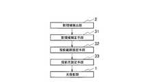
制御部3は、その機能的な構成として、図2に示すように影領域補正手段31、投影範囲設定手段32、投影光設定手段33を有する。 As a functional configuration, the
影領域補正手段31は、影領域検出部2により検出された影領域13を取得する。影領域13は、例えば影領域検出部2によって画像データによって検出される。影領域補正手段31は、画像データのうち、被照射物体11の影に相当する暗い画素を影領域13として認識する。 The shadow
影領域補正手段31は、光投影部1の投影領域と影領域検出部2により検出された影領域13とが床面12a及び背面12b上で一致するように影領域検出部2で検出された影領域13を補正する。このとき、影領域補正手段31は、光投影部1によって被照射物体11を含む広い範囲に投影光L1が照射された時における影領域検出部2によって検出された影領域13を取得する。そして、影領域補正手段31は、取得した影領域13の位置や形状から、その影領域13の位置を投影する投影光L1を特定する。 The shadow area correction means 31 is detected by the shadow
影領域補正手段31による影領域13の検出方法としては、影領域検出部2としてカメラを用いて床面12a及び背面12bを撮影し、撮影画像の輝度変化や色彩変化から影領域13を抽出する。そして、影領域補正手段31は、影領域13と対応する光投影部1による投影光L1の特定方法としては、特定の床面12a及び背面12bに対する光投影部1の光軸と影領域検出部2の光軸を合わせるように投影変換する。これにより、影領域補正手段31は、床面12a及び背面12b上における光投影部1の投影箇所と影領域13の検出箇所とを一致させる。すなわち、光投影部1の投影画像と影領域検出部2の撮影画像を同一の平面状で一致するように補正する画像処理を行う。 As a method of detecting the
具体的には、図3(a)に斜視図、図3(b)に上面図、図3(c)に正面図を示して説明する。光投影部1によって投影光L1が投影可能な投影範囲は、12a−1、12b−1、12b−6である。一方、影領域検出部2による影領域13の検出可能範囲は、12a−1と12b−1に加え、12a−2、12a−3、12b−2、12b−4である。したがって、図3(b)、(c)に示した太枠内の12a−1と12b−1が、光投影部1によって投影光L1が投影可能な投影範囲と、影領域検出部2による影領域13の検出可能範囲とが重複する範囲となる。このような重複範囲では、投影光L1と影領域13との対応関係が明確である。すなわち、影領域13の画素が分かれば、投影光L1のどの部分の光か分かる。したがって、この重複範囲は、投影光L1の届く範囲と影領域13の検出可能範囲の小さい方であり、それは大きい方の一部となる。 Specifically, FIG. 3A is a perspective view, FIG. 3B is a top view, and FIG. 3C is a front view. Projection ranges in which the projection light L1 can be projected by the
影領域補正手段31は、影領域検出部2により取得した画像の各画素と、光投影部1の投影光L1との対応関係を事前に計算して、対応マップを作成して蓄積しておく。影領域補正手段31は、実際に影領域検出部2により影領域13を撮像した画像を取得した場合に、当該対応マップを参照し、影領域13に対応する投影光L1の光の特定を行う。 The shadow
投影範囲設定手段32は、影領域補正手段31により補正された影の補正領域を光投影範囲とし、それ以外の領域を非光投影範囲に設定する。 The projection
また、投影範囲設定手段32は、影領域13に対応する領域を第1投影範囲、それ以外を第2投影範囲としても良い。投影範囲設定手段32は、第1投影範囲、第2投影範囲にそれぞれ個別に投影光L1を設定できる。これにより、被照射物体11が存在する領域と、それ以外の領域に異なる投影光L1を投影することができる。 Further, the projection range setting means 32 may set the region corresponding to the
投影光設定手段33は、投影範囲設定手段32により設定された光投影範囲に投影する光を設定する。具体的には、投影光設定手段33は、投影範囲設定手段32で設定した投影範囲、もしくは、第1投影範囲、第2投影範囲に投影する光の設定を行う。例えば、それぞれ個別に投影する照明光、映像光の設定を行う。また、投影光設定手段33は、投影範囲の設定以外に、投影光L1の照度、輝度、光度、光束、色温度、演色性を含む要素を特定できる機能を有しても良い。これにより、光投影装置は、投影光L1を照明用途のパラメータで設定することができる。 The projection
また、投影範囲設定手段32は、第1投影範囲に黒い光を設定しても良い。これにより、被照射物体11に光を投影しないことも可能となる。 Further, the projection range setting means 32 may set black light in the first projection range. Thereby, it becomes possible not to project light on the
このような光投影装置は、例えば図4に示すように動作する。 Such an optical projection apparatus operates as shown in FIG. 4, for example.
光投影装置は、先ずステップS1において、光投影部1によって、被照射物体11,床面12a及び背面12bを含む投影可能範囲全体に投影光L1を投影する。 First, in step S1, the light projection apparatus projects the projection light L1 onto the entire projectable range including the irradiated
次のステップS2において、影領域検出部2は、光投影部1によって投影光L1が投影されている状態で、床面12a及び背面12b上に生じた影領域13を検出する。 In the next step S2, the shadow
次のステップS3において、影領域補正手段31は、影領域検出部2により検出された画像データを参照して、影領域13に相当する画像領域が存在するか否かを判定する。これにより、影領域補正手段31は、影領域13を検出したか否かを判定する。影領域13を検出した場合にはステップS4に処理を進め、影領域13を検出していない場合にはステップS1に処理を戻す。ステップS1に処理を戻した場合、光投影部1から投影光L1を投影し、影領域補正手段31によって影が抽出されるまでステップS1乃至ステップS3を繰り返す。 In the next step S <b> 3, the shadow
ステップS4において、影領域補正手段31は、検出した影領域13に対応する光投影部1の投影光L1を特定する。このとき、上述したように、床面12a及び背面12bにおける光投影部1の光軸と影領域検出部2の光軸を合わせるように投影変換し、その床面12a及び背面12b上における投影箇所と影領域13の検出箇所とを一致させる。具体的には、影領域補正手段31は、上記のように投影変換演算を行うか、又は、事前に用意された対応マップを使用して投影変換を行うことにより、影領域13に対する投影光L1の特定を行う。 In step S <b> 4, the shadow
ステップS5において、投影範囲設定手段32は、被照射物体11のみに投影光L1を照射する場合には、影領域補正手段31により補正された影領域13の補正領域を光投影範囲とし、それ以外の領域を非光投影範囲に設定する。又は、投影範囲設定手段32は、被照射物体11と床面12a及び背面12bに異なる投影光L1を投影する場合には、影領域13に対応する領域を第1投影範囲、それ以外を第2投影範囲とする。 In step S5, when only the irradiated
ステップS6において、投影光設定手段33は、投影範囲設定手段32により設定された光投影範囲に投影する投影光L1を設定する。例えば、投影光設定手段33は、照明光を投影することを設定する。又は、投影光設定手段33は、第1投影範囲及び第2投影範囲が設定された場合には、それぞれ個別に投影される照明光や映像光を設定する。 In step S <b> 6, the projection
例えば、投影光L1が照明光の場合、照度、輝度、光度、光束、色温度、演色性の何れか含む要素を設定する。また、投影光設定手段33は、第1投影範囲に黒い光を設定し、第2投影範囲に照明光や映像を設定することで、被照射物体11に光を投影しないことも可能となる。また、投影光L1が映像光の場合、投影光設定手段33は投影光L1として投影する映像を設定する。 For example, when the projection light L1 is illumination light, an element including any of illuminance, luminance, luminous intensity, light flux, color temperature, and color rendering properties is set. Further, the projection light setting means 33 can set the black light in the first projection range and set the illumination light or video in the second projection range, so that the light is not projected onto the
以上説明したように、第1実施形態として示した光投影装置によれば、被照射物体11の影領域13を検出し、光投影部1の投影領域と影領域13とが床面12a及び背面12b上で一致するように補正して、当該補正した影領域13を光投影範囲とする。これにより、光投影部1は、設定された光投影範囲に投影光L1を投影することにより、被照射物体11が存在する範囲に投影光L1を投影することができる。したがって、この光投影装置によれば、被照射物体11に対してのみ投影光L1を照射できる。 As described above, according to the light projection device shown as the first embodiment, the
また、この光投影装置は、事前に被照射物体11の形状を計測等する必要がなく、被照射物体11に対して過不足のない投影光L1を照射できる。 Moreover, this light projection apparatus does not need to measure the shape of the
更に、この光投影装置によれば、投影光L1の照度、輝度、光度、光束、色温度、演色性の何れかを含む要素を特定することができるので、被照射物体11に投影する投影光L1を調整できる。 Furthermore, according to this light projection device, it is possible to specify an element including any of the illuminance, luminance, luminous intensity, luminous flux, color temperature, and color rendering properties of the projection light L1, so that the projection light projected onto the
更に、この光投影装置によれば、被照射物体11に照射する範囲としての影領域13を第1投影範囲とし、それ以外の床面12a及び背面12bといった領域を第2投影範囲とする。これにより、この光投影装置によれば、第1投影範囲と第2投影範囲に投影する投影光L1を個別に設定し、それぞれに異なる投影光L1を投影することができる。 Furthermore, according to this light projection device, the
このような光投影装置において、光投影部1から投影光L1を投影する場合に、光投影部1は、照明光としての投影光L1を投影しても良い。この場合、光投影装置は、制御部3の制御によって、光投影部1により照明光としての投影光L1を投影するための照明データを生成する照明データ生成部による照明データの生成タイミングを調整可能であることが望ましい。また、制御部3は、光投影部1による照明光の照射タイミングが調整可能とすることが望ましい。 In such a light projection device, when projecting the projection light L1 from the
ここで、投影光L1としての照明光の照射タイミングのみ自由に制御することにより、照明データの生成は常に行われていても、照明光の照射タイミングに合わせて生成タイミングが制御されていても、眼に見える効果としては同じである。これに対し、照明データの生成タイミングを制御することにより、照明データの生成処理を停止させることもでき、制御部3の処理負荷を軽減することができる。これにより、制御部3は、影領域補正処理や、投影範囲設定処理、投影光設定処理に処理負荷を与えることができる。また、制御部3による照明データの生成処理を停止させることにより、制御部3の消費電力を抑制できる。 Here, by freely controlling only the irradiation timing of the illumination light as the projection light L1, even if the generation of the illumination data is always performed or the generation timing is controlled in accordance with the irradiation timing of the illumination light, The visible effect is the same. On the other hand, by controlling the generation timing of the illumination data, the illumination data generation process can be stopped, and the processing load on the
[第2実施形態]
つぎに、第2実施形態に係る光投影装置について説明する。なお、上述の第1実施形態と同様の部分については同一符号を付することによりその詳細な説明を省略する。[Second Embodiment]
Next, an optical projection apparatus according to the second embodiment will be described. In addition, about the part similar to the above-mentioned 1st Embodiment, the detailed description is abbreviate | omitted by attaching | subjecting the same code | symbol.
第2実施形態としての光投影装置は、被照射物体11が変形又は移動した場合であっても、被照射物体11に投影光L1を投影できるものである。 The light projection device as the second embodiment is capable of projecting the projection light L1 onto the
この光投影装置は、影領域検出部2による影検出動作、影領域補正手段31による影領域の補正動作、及び、投影範囲設定手段32による投影範囲設定動作を、任意の時間間隔で行う。これにより、被照射物体11の位置や形状が変化しても、自動で投影光L1の投影範囲を更新し、被照射物体11とそれ以外の床面12a及び背面12bに別々の投影光L1を投影する動作を維持できる。 This light projection apparatus performs a shadow detection operation by the shadow
具体的には、被照射物体11が変形又は移動したときに、影領域検出部2で影領域13の変形又は移動を検出し、当該変形又は移動を影領域補正手段31が認識した場合に、再度、光投影部1により、当該光投影部1の投影可能範囲に投影光L1を照射する。これにより、影領域検出部2は、被照射物体11の変形又は移動した結果としての影領域13を検出でき、当該影領域13に対応して投影光L1を被照射物体11に投影できる。 Specifically, when the
ここで、影領域13の変形又は移動を検出するための光投影部1による投影光L1の照射は、一定間隔で極めて短時間のみ投影可能範囲の全体を照射することが望ましい。この動作は、上述した光投影装置に対して簡単に実装でき、また、影領域13を確実且つ正確に検出する上で有効である。しかし、輝度のチラツキが発生する可能性がある。 Here, the projection of the projection light L1 by the
この輝度のチラツキの問題に鑑みると、影領域13の変形又は移動のみを検出することが望ましい。この場合、影領域補正手段31は、時間的に前後する影領域13の形状の差分を検出して、影領域13の変形又は移動を検出する。この光投影装置は、影領域13の変形又は移動のみを影領域検出部2により検出して、影領域補正手段31にて影領域13を補正し、投影範囲設定手段32により投影光L1の投影範囲を設定する。これによっても、影領域検出部2は、被照射物体11の変形又は移動した結果としての影領域13を検出でき、当該影領域13に対応して投影光L1を被照射物体11に投影できる。 In view of this luminance flicker problem, it is desirable to detect only the deformation or movement of the
この光投影装置によれば、光投影部1が移動又は変形しても、自動で光投影部1の投影範囲を更新し、被照射物体11とそれ以外の領域に別々の投影を行う効果を維持することができる。 According to this light projection device, even if the
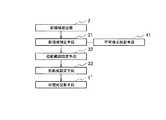
また、被照射物体11が変形又は移動する場合にでも被照射物体11に投影光L1を投影できる他の構成例としては、図5に示すように、不可視光投影手段41を用いても良い。不可視光投影手段41は、被照射物体11等を見る者が見えない不可視光を投影する。不可視光投影手段41は、光投影部1に相当する可視光投影手段1’と同じ投影範囲となるよう配置されている。例えば、可視光投影手段1’の投影軸と同じ投影軸となるよう配置されている。不可視光投影手段41は、例えば赤外線光源が使用可能である。この場合、影領域検出部2は、赤外線カメラを使用する必要がある。 As another configuration example in which the projection light L1 can be projected onto the
このような光投影装置は、図6に示すように、不可視光投影手段41が影領域補正手段31と接続されている。光投影装置は、影領域13を検出するときに、影領域補正手段31によって不可視光投影手段41が駆動される。これにより、光投影装置は、不可視光投影手段41により不可視光が投影され、当該不可視光によって発生した影領域13を影領域検出部2が検出可能となっている。これにより、影領域補正手段31は、影領域13が検出されたことによって、画像データ内の影領域13を認識できる。 In such a light projection apparatus, as shown in FIG. 6, the invisible light projection means 41 is connected to the shadow region correction means 31. In the light projection apparatus, when the
また、不可視光投影手段を設ける他の構成例としては、図7に示すように、図6の不可視光投影手段41の位置を41’とし、当該不可視光投影手段41’から投影された不可視光を反射する不可視光反射手段42を設けても良い。不可視光反射手段42は、例えば光投影部1からの投影光L1(可視光)は透過し、不可視光投影手段41’からの不可視光は反射するミラーを使用することができる。 Further, as another configuration example in which the invisible light projecting unit is provided, as shown in FIG. 7, the position of the invisible
この光投影装置は、可視光投影手段1’から投影された可視光を、不可視光投影手段41’によって遮らない。したがって、可視光投影手段1’によって全ての投影可能範囲に可視光を投影し、不可視光投影手段41’によって不可視光反射手段42を介して、可視光投影手段1’の投影可能範囲に不可視光を投影できる。 In this light projection device, the visible light projected from the visible
以上のように、この光投影装置によれば、被照射物体11が変形又は移動した場合であっても、当該変形又は移動による影領域13の変化を検出して、投影光L1の投影範囲を更新することができる。したがって、この光投影装置によれば、被照射物体11の変形又は移動に追従できる。 As described above, according to this light projection device, even when the
[第3実施形態]
つぎに、第3実施形態に係る光投影装置について説明する。なお、上述の実施形態と同様の部分については同一符号を付することによりその詳細な説明を省略する。[Third Embodiment]
Next, an optical projection apparatus according to the third embodiment will be described. Note that parts similar to those in the above-described embodiment are denoted by the same reference numerals, and detailed description thereof is omitted.
第3実施形態としての光投影装置は、図8及び図9に示すように、2以上の光投影部1a、1bを備えている。これにより、光投影装置は、2以上の位置から投影光を投影するよう構成されている。また、光投影装置は、投影範囲設定手段32が、各光投影部1a、1bに対応した複数の投影範囲を設定する。なお、この実施形態では2台の光投影部1a、1bであるが、2台より多くても良い。 As shown in FIGS. 8 and 9, the light projection apparatus as the third embodiment includes two or more
この光投影装置は、例えば、光投影部1a、1bの投影範囲によって、全体の投影範囲を広くすることができる。これにより、投影範囲が狭い光投影部1を使用した場合や、必要とされる投影範囲が広い場合であっても、1台の光投影部1では投影できない範囲に投影光L1を投影できる。 This light projection device can widen the entire projection range by, for example, the projection ranges of the
この光投影装置は、例えば、被照射物体11を異なる角度から投影するよう光投影部1a、1bを配置する。これにより、光投影装置は、光投影部1a、1bによって多方向から投影光L1を被照射物体11や床面12a及び背面12bに対して投影できる。 In this light projection apparatus, for example, the
また、光投影装置は、光投影部1a、1bの投影範囲が重複するよう光投影部1a、1bを配置しても良い。これにより、光投影部1a、1bによって投影された投影光L1のうち重複している範囲における投影光L1の輝度を向上させることができる。 In the light projection apparatus, the
[第4実施形態]
つぎに、第4実施形態に係る光投影装置について説明する。なお、上述の実施形態と同様の部分については同一符号を付することによりその詳細な説明を省略する。[Fourth Embodiment]
Next, an optical projection apparatus according to the fourth embodiment will be described. Note that parts similar to those in the above-described embodiment are denoted by the same reference numerals, and detailed description thereof is omitted.
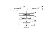
第4実施形態としての光投影装置は、図10及び図11に示すように、2以上の影領域検出部2a,2bを備えている。これにより、光投影装置は、2以上の位置から影領域13を検出するよう構成されている。 As shown in FIGS. 10 and 11, the light projection apparatus as the fourth embodiment includes two or more shadow
この光投影装置は、影領域補正手段31が、各影領域検出部2a,2bに対応した影領域13の補正領域を算出して、投影範囲設定手段32によって投影範囲を設定する。この光投影装置は、投影範囲設定手段32が、各影領域13の補正領域を統合して、光投影部1の投影範囲を設定する。なお、この実施形態では2台の光投影部1a、1bであるが、2台より多くても良い。 In this light projection apparatus, the shadow
この光投影装置は、影領域13を検出する位置を2以上としているので、影領域補正手段31が各影領域検出位置に対応した影領域13の補正領域を算出する。また、投影範囲設定手段32は、各補正された影領域13を統合して、光投影部1の投影範囲を設定する。 In this light projection apparatus, since the number of positions where the
このような光投影装置によれば、2以上の位置から影領域13を検出するので、影領域13の検出範囲が拡張できる。また、この光投影装置によれば、被照射物体11の床面12a及び背面12bの影領域13を多方向から検出できるので、影領域検出部2a,2bからみた影領域13の死角を抑制でき、影領域13の検出精度の向上が可能となる。これは、被照射物体11と影領域検出部2a,2bとの位置関係によっては、影領域検出部2a,2bが被照射物体11の床面12a及び背面12bを観察できない部分(死角)が存在してしまう。これに対し、2以上の位置から影領域13を検出することで、多方面から床面12a及び背面12bの影領域13を計測することができ、死角をなくすことができることによる。 According to such an optical projection device, the
なお、上述したように、2以上の位置から投影光L1を投影する光投影装置と組み合わせても良いのは勿論である。 Of course, as described above, it may be combined with an optical projection device that projects the projection light L1 from two or more positions.
[第5実施形態]
つぎに、第5実施形態に係る光投影装置について説明する。なお、上述の実施形態と同様の部分については同一符号を付することによりその詳細な説明を省略する。[Fifth Embodiment]
Next, an optical projection apparatus according to a fifth embodiment will be described. Note that parts similar to those in the above-described embodiment are denoted by the same reference numerals, and detailed description thereof is omitted.
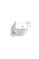
第5実施形態としての光投影装置は、図12に示すように、影領域検出部2を、被照射物体11の床面12a及び背面12bに埋め込まれた光センサ50としている。すなわち、上述した実施形態においては、影領域検出部2をカメラ等として説明したが、これに代えて、多数の光センサ50を備えている。 In the optical projection apparatus as the fifth embodiment, as shown in FIG. 12, the shadow
各光センサ50は、自身が検出した光強度信号を影領域補正手段31に供給する。影領域補正手段31は、各光センサ50の光強度信号及び位置情報から、床面12a及び背面12bのうちの影領域13を特定する。このとき、影領域補正手段31は、光強度信号の変化である床面12a及び背面12bの輝度変化を検出しても良く、色彩変化を検出しても良い。これにより、影領域補正手段31は、被照射物体11が変形又は移動しても、影領域13を追従して検出できる。 Each
影領域補正手段31は、光投影部1の投影領域と影領域13とが床面12a及び背面12b上で一致するように影領域13を補正する。ここで、影領域補正手段31は、各光センサ50と光投影部1の投影範囲との対応マップを事前に作成しておき、対応マップを参照して、影領域13に対応する光投影部1からの投影光L1を決定しても良い。投影範囲設定手段32は、影領域補正手段31によって補正された影領域13を光投影部1の投影範囲として設定する。 The shadow
以上のように、この光投影装置によれば、画像データではなく光センサ50の検出結果によって影領域13を特定するので、影領域13の検出精度を向上させることができる。その結果、光投影装置は、被照射物体11に対して精度の高い光投影部1の投影範囲を設定できる。また、この光投影装置によれば、影領域検出部2としてのカメラを複数台使用しなくても、死角無く影領域13を検出できる。 As described above, according to this light projection device, the
なお、上述の実施の形態は本発明の一例である。このため、本発明は、上述の実施形態に限定されることはなく、この実施の形態以外であっても、本発明に係る技術的思想を逸脱しない範囲であれば、設計等に応じて種々の変更が可能であることは勿論である。 The above-described embodiment is an example of the present invention. For this reason, the present invention is not limited to the above-described embodiment, and various modifications can be made depending on the design and the like as long as the technical idea according to the present invention is not deviated from this embodiment. Of course, it is possible to change.
1 光投影部、可視光投影手段
2 影領域検出部
3 制御部
11 被照射物体
12a 床面
12b 背面
13 影領域
31 影領域補正手段
32 投影範囲設定手段
33 投影光設定手段
41 不可視光投影手段
42 不可視光反射手段
50 光センサDESCRIPTION OF
Claims (10)
Translated fromJapanese物体及び当該物体の背面が投影可能範囲とされ、投影光を投影する光投影手段と、
前記光投影手段から投影された投影光によって物体の背面に発生する影の領域を検出する影領域検出手段と、
前記光投影手段の投影領域と前記影領域検出手段により検出された影領域とが物体の背面上で一致するように前記影領域検出手段で検出された影領域を補正する影領域補正手段と、
前記影領域補正手段により補正された影領域を光投影範囲とし、当該影領域以外の領域を非光投影範囲に設定する投影範囲設定手段と、
前記投影範囲設定手段により設定された光投影範囲に投影する投影光を設定する投影光設定手段を備え、
前記光投影手段は、前記投影範囲設定手段により設定された光投影範囲に、前記投影光設定手段により設定された投影光を投影することにより、前記物体が存在する範囲に光を投影することを特徴とする光投影装置。An optical projection apparatus that projects light onto an object arranged in an arbitrary space,
A light projecting unit configured to project an object and a rear surface of the object as a projectable range;
A shadow area detecting means for detecting a shadow area generated on the back of the object by the projection light projected from the light projecting means;
A shadow region correction unit that corrects the shadow region detected by the shadow region detection unit so that the projection region of the light projection unit and the shadow region detected by the shadow region detection unit coincide on the back of the object;
A shadow area corrected by the shadow area correction means as a light projection range, and a projection range setting means for setting an area other than the shadow area as a non-light projection range;
A projection light setting means for setting projection light to be projected onto the light projection range set by the projection range setting means,
The light projection unit projects light onto a range where the object exists by projecting the projection light set by the projection light setting unit onto the light projection range set by the projection range setting unit. A light projection device.
前記投影光設定手段が、前記第1投影範囲と前記第2投影範囲に投影する光を個別に設定し、
前記光投影手段の投影可能領域において、物体が存在する第1投影範囲と、物体が存在しない第2投影範囲とに分割し、前記光投影手段が、当該第1投影範囲と第2投影範囲とに異なる光を投影することを特徴とする請求項1又は請求項2に記載の光投影装置。The shadow area corrected by the shadow area correction means is a first projection range, and an area other than the shadow area is a second projection range,
The projection light setting means individually sets light to be projected onto the first projection range and the second projection range;
In the projectable area of the light projection unit, the light projection unit is divided into a first projection range in which an object exists and a second projection range in which no object exists, and the light projection unit includes the first projection range and the second projection range. The light projection apparatus according to claim 1, wherein different light is projected onto the light projection apparatus.
前記投影範囲設定手段が、各光投影位置ごとに投影範囲を設定することを特徴とする請求項1乃至請求項5の何れか一項に記載の光投影装置。The light projection means is configured to project projection light from two or more positions;
6. The light projection apparatus according to claim 1, wherein the projection range setting unit sets a projection range for each light projection position.
前記影領域補正手段が、各影領域検出位置ごとに補正した影領域を算出し、
前記投影範囲設定手段が、前記影領域補正手段により補正された各影領域を統合して前記光投影手段の投影範囲を設定すること
を特徴とする請求項1乃至請求項5の何れか一項に記載の光投影装置。The shadow area detecting means is configured to detect a shadow area from two or more positions,
The shadow area correction means calculates a corrected shadow area for each shadow area detection position,
6. The projection range setting unit sets the projection range of the light projection unit by integrating the shadow regions corrected by the shadow region correction unit. 6. The light projection device described in 1.
前記投影光設定手段は、前記光投影手段から投影する光として映像を設定すること
を特徴とする請求項1乃至請求項9の何れか一項に記載の光投影装置。The light projection means projects an image;
The light projection device according to any one of claims 1 to 9, wherein the projection light setting unit sets an image as light projected from the light projection unit.
Priority Applications (5)
| Application Number | Priority Date | Filing Date | Title |
|---|---|---|---|
| JP2011114709AJP5643153B2 (en) | 2011-05-23 | 2011-05-23 | Optical projection device |
| PCT/JP2012/060696WO2012160913A1 (en) | 2011-05-23 | 2012-04-20 | Light projection device |
| US14/113,695US9217865B2 (en) | 2011-05-23 | 2012-04-20 | Light projection device |
| EP12788927.7AEP2693103A4 (en) | 2011-05-23 | 2012-04-20 | Light projection device |
| CN201280020880.8ACN103502721B (en) | 2011-05-23 | 2012-04-20 | light projection device |
Applications Claiming Priority (1)
| Application Number | Priority Date | Filing Date | Title |
|---|---|---|---|
| JP2011114709AJP5643153B2 (en) | 2011-05-23 | 2011-05-23 | Optical projection device |
Publications (2)
| Publication Number | Publication Date |
|---|---|
| JP2012243665A JP2012243665A (en) | 2012-12-10 |
| JP5643153B2true JP5643153B2 (en) | 2014-12-17 |
Family
ID=47216997
Family Applications (1)
| Application Number | Title | Priority Date | Filing Date |
|---|---|---|---|
| JP2011114709AActiveJP5643153B2 (en) | 2011-05-23 | 2011-05-23 | Optical projection device |
Country Status (5)
| Country | Link |
|---|---|
| US (1) | US9217865B2 (en) |
| EP (1) | EP2693103A4 (en) |
| JP (1) | JP5643153B2 (en) |
| CN (1) | CN103502721B (en) |
| WO (1) | WO2012160913A1 (en) |
Families Citing this family (11)
| Publication number | Priority date | Publication date | Assignee | Title |
|---|---|---|---|---|
| US20130310652A1 (en)* | 2012-05-15 | 2013-11-21 | The Cleveland Clinic Foundation | Integrated surgical task lighting |
| JP2015043556A (en)* | 2013-07-24 | 2015-03-05 | 株式会社リコー | Information processor, image projection system and program |
| JP2015139177A (en)* | 2014-01-24 | 2015-07-30 | 株式会社東芝 | Controller, control method, and image projection system |
| US9746370B2 (en)* | 2014-02-26 | 2017-08-29 | Sensity Systems Inc. | Method and apparatus for measuring illumination characteristics of a luminaire |
| JP6410079B2 (en) | 2014-06-26 | 2018-10-24 | パナソニックIpマネジメント株式会社 | Optical projection device and illumination device using the same |
| US20160071486A1 (en)* | 2014-09-09 | 2016-03-10 | Cisco Technology, Inc. | Immersive projection lighting environment |
| US20170102288A1 (en)* | 2015-10-13 | 2017-04-13 | Fluke Corporation | Three-dimensional inspection of optical communication links |
| CN107087148A (en)* | 2017-06-30 | 2017-08-22 | 合肥久能图文科技有限公司 | A kind of projector monitors self-adjusting system |
| ES2728787B2 (en)* | 2018-04-25 | 2021-02-09 | Defensya Ingenieria Int S L | SYSTEM AND PROCEDURE TO CREATE, MODULATE AND DETECT SHADOWS IN SYSTEMS WITH CONTROL BASED ON A REMOTE VISUALIZATION SYSTEM |
| TR201909524A2 (en)* | 2019-06-26 | 2020-11-23 | Atatuerk Ueniversitesi Rektoerluegue Bilimsel Arastirma Projeleri Bap Koordinasyon Birimi | INTELLIGENT, ADAPTABLE WAVE LIGHTING SYSTEM |
| US12243239B2 (en)* | 2019-08-30 | 2025-03-04 | Ntt Docomo, Inc. | Projection controlling apparatus and projection system |
Family Cites Families (13)
| Publication number | Priority date | Publication date | Assignee | Title |
|---|---|---|---|---|
| US6361173B1 (en)* | 2001-02-16 | 2002-03-26 | Imatte, Inc. | Method and apparatus for inhibiting projection of selected areas of a projected image |
| US6984039B2 (en)* | 2003-12-01 | 2006-01-10 | Eastman Kodak Company | Laser projector having silhouette blanking for objects in the output light path |
| US20060244921A1 (en)* | 2005-04-28 | 2006-11-02 | Childers Winthrop D | Contrast enhancement by selectively using light attenuating modulator |
| US7984995B2 (en)* | 2006-05-24 | 2011-07-26 | Smart Technologies Ulc | Method and apparatus for inhibiting a subject's eyes from being exposed to projected light |
| US7612805B2 (en)* | 2006-07-11 | 2009-11-03 | Neal Solomon | Digital imaging system and methods for selective image filtration |
| JP4270264B2 (en) | 2006-11-01 | 2009-05-27 | セイコーエプソン株式会社 | Image correction apparatus, projection system, image correction method, image correction program, and recording medium |
| JP2008135345A (en)* | 2006-11-29 | 2008-06-12 | Toshiba Lighting & Technology Corp | Lighting fixture and lighting system |
| TWI325998B (en)* | 2006-12-20 | 2010-06-11 | Delta Electronics Inc | Projection apparatus and system |
| US8681224B2 (en)* | 2007-06-26 | 2014-03-25 | Dublin City University | Method for high precision lens distortion calibration and removal |
| JP4925369B2 (en)* | 2007-07-26 | 2012-04-25 | パナソニック株式会社 | Lighting device |
| JP4270329B1 (en)* | 2007-10-17 | 2009-05-27 | パナソニック電工株式会社 | Lighting device |
| JP4341723B2 (en) | 2008-02-22 | 2009-10-07 | パナソニック電工株式会社 | Light projection device, lighting device |
| US8290208B2 (en)* | 2009-01-12 | 2012-10-16 | Eastman Kodak Company | Enhanced safety during laser projection |
- 2011
- 2011-05-23JPJP2011114709Apatent/JP5643153B2/enactiveActive
- 2012
- 2012-04-20EPEP12788927.7Apatent/EP2693103A4/ennot_activeWithdrawn
- 2012-04-20WOPCT/JP2012/060696patent/WO2012160913A1/enactiveApplication Filing
- 2012-04-20CNCN201280020880.8Apatent/CN103502721B/ennot_activeExpired - Fee Related
- 2012-04-20USUS14/113,695patent/US9217865B2/ennot_activeExpired - Fee Related
Also Published As
| Publication number | Publication date |
|---|---|
| WO2012160913A1 (en) | 2012-11-29 |
| CN103502721B (en) | 2015-06-24 |
| JP2012243665A (en) | 2012-12-10 |
| EP2693103A4 (en) | 2015-08-19 |
| US9217865B2 (en) | 2015-12-22 |
| EP2693103A1 (en) | 2014-02-05 |
| US20140043545A1 (en) | 2014-02-13 |
| CN103502721A (en) | 2014-01-08 |
Similar Documents
| Publication | Publication Date | Title |
|---|---|---|
| JP5643153B2 (en) | Optical projection device | |
| CN105122943B (en) | A method of characterizing a light source and a mobile device | |
| US10595014B2 (en) | Object distance determination from image | |
| JP6111706B2 (en) | Position detection apparatus, adjustment method, and adjustment program | |
| EP2823751B1 (en) | Eye gaze imaging | |
| JP7090446B2 (en) | Image processing equipment | |
| CN103048853B (en) | Light suggestion device and image collecting device | |
| KR20110123257A (en) | Clarify touch pointers with active display feedback | |
| US20230102878A1 (en) | Projector and projection method | |
| US9733728B2 (en) | Position detecting device and position detecting method | |
| JP2007086545A (en) | Information presenting system | |
| JP5601179B2 (en) | Gaze detection apparatus and gaze detection method | |
| US10397534B2 (en) | Projection display and image correction method | |
| JP5319999B2 (en) | Lighting device | |
| JP2018537884A (en) | How to take a picture with a mobile device | |
| JP6492588B2 (en) | Projector and projector control method | |
| KR20160149883A (en) | An apparatus for inspecting a lens defect | |
| JP2024030668A (en) | Lighting system and photography system | |
| US11755152B2 (en) | Projector with detection function for stabilizing intensity distribution of an irradiation beam | |
| US20230412782A1 (en) | Display method and display system | |
| JP2020076675A5 (en) | ||
| TW201325308A (en) | Illumination control system and illumination control method | |
| CN107018393A (en) | The control method of projecting apparatus and projecting apparatus | |
| KR20150063857A (en) | Curved display device | |
| JP2019133539A (en) | Image processing apparatus and image processing method |
Legal Events
| Date | Code | Title | Description |
|---|---|---|---|
| A621 | Written request for application examination | Free format text:JAPANESE INTERMEDIATE CODE: A621 Effective date:20140207 | |
| TRDD | Decision of grant or rejection written | ||
| A01 | Written decision to grant a patent or to grant a registration (utility model) | Free format text:JAPANESE INTERMEDIATE CODE: A01 Effective date:20141007 | |
| A61 | First payment of annual fees (during grant procedure) | Free format text:JAPANESE INTERMEDIATE CODE: A61 Effective date:20141030 | |
| R151 | Written notification of patent or utility model registration | Ref document number:5643153 Country of ref document:JP Free format text:JAPANESE INTERMEDIATE CODE: R151 |